1
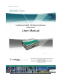
Intelimax User Manual
-1-
Intelimax User Manual
TABLE OF CONTENTS
CONTACT INFORMATION ........................................................................- 6 RF EXPOSURE AND ELECTRICAL SAFETY COMPLIANCE ...........................- 7 Caution .............................................................................................- 7 General Safety ..................................................................................- 8 Vehicle Safety ...................................................................................- 9 Potentially Unsafe Areas ...................................................................- 9 REVISION HISTORY .............................................................................. - 10 Intelimax USER MANUAL ...................................................................... - 11 Disclaimers ..................................................................................... - 11 INTRODUCTION .................................................................................... - 12 Overview ......................................................................................... - 12 Intelimax Features .......................................................................... - 12 General Features .......................................................................... - 12 Extended Features ........................................................................ - 12 Security Features ......................................................................... - 12 Frequency Bands .......................................................................... - 13 Data Speeds ................................................................................ - 13 Environmental Specifications.......................................................... - 13 Dimensions .................................................................................. - 13 Connections ................................................................................. - 13 Mounting ..................................................................................... - 13 LED Lights ................................................................................... - 13 Module Approvals ......................................................................... - 13 Modem Approvals ......................................................................... - 14 Compliance .................................................................................. - 14 Power Source ............................................................................... - 14 Operating Systems ....................................................................... - 14 Hardware compatibility ........................................................................ - 15 Intelimax Setup .................................................................................... - 16 Connecting to the Intelimax ............................................................ - 17 TCP/IP Connection - Recommended ............................................... - 17 Serial Port Connection .................................................................... - 18 GUI Connection Debugging ............................................................. - 19 Modem Configuration ...................................................................... - 20 -2-
Intelimax User Manual
Modem Status Tab .......................................................................... - 20 Scheduler ........................................................................................ - 26 Scheduler Day of the Week: ............................................................ - 26 Scheduler by Duration..................................................................... - 28 Serial Configuration ........................................................................ - 29 IP Stack Configuration .................................................................... - 31 Modem Emulation TAB .................................................................... - 38 Dynamic DNS .................................................................................. - 40 PPP Server ...................................................................................... - 41 Administration ................................................................................ - 47 Telnet and SSH login ....................................................................... - 47 Syslog ............................................................................................. - 48 RSSI logging ................................................................................... - 48 Administrators ................................................................................ - 48 maXconnect .................................................................................... - 48 System settings page ...................................................................... - 50 AT over IP ....................................................................................... - 50 Debug ............................................................................................. - 50 SNMP Configuration ........................................................................ - 51 SNTP ............................................................................................... - 53 IP Stack Functions .......................................................................... - 54 IP Stack Connect AT Command ....................................................... - 54 IP Stack Disconnect AT Command ................................................... - 54 IP Stack Connect Button ................................................................. - 55 IP Stack Disconnect Button ............................................................. - 55 Send CR, LF ..................................................................................... - 55 Send Button .................................................................................... - 55 System Functions ............................................................................ - 55 Clear Output.................................................................................... - 55 Save Output .................................................................................... - 55 Save Config ..................................................................................... - 55 Load Config ..................................................................................... - 55 Factory Setting ............................................................................... - 55 Firmware Upgrade .......................................................................... - 56 SMS Commands (IP modes) ................................................................. - 57 SMS Commands (Serial modem modes) ............................................... - 58 -3-
Intelimax User Manual
PROGRAM INTELIMAX VIA CIRCUIT CALL ............................................. - 59 LED Functionality .................................................................................. - 61 Modem Debugging ................................................................................ - 62 Local Connection Checking .............................................................. - 62 Remote Connection Checking .......................................................... - 62 Telnet / SSH Commands ....................................................................... - 64 Connecting to the modem via telnet ............................................... - 64 Extended / Intelimax Specific AT Command Set (IP Stack Modes) ....... - 77 Device Information ......................................................................... - 77 Wan extension function .................................................................. - 77 WAN authentication ........................................................................ - 78 Periodic reset .................................................................................. - 79 WAN scheduler................................................................................ - 79 IP Stack setting .............................................................................. - 79 SNMP .............................................................................................. - 80 DDNS .............................................................................................. - 80 System ............................................................................................ - 81 maXconnect .................................................................................... - 82 Serial (UART) port .......................................................................... - 82 Engine Band .................................................................................... - 82 Check IP address of the WAN side .................................................. - 84 FTP.................................................................................................. - 84 Signal Strength ............................................................................... - 87 Open PPP connection ...................................................................... - 87 Close PPP connection ...................................................................... - 87 Open TCP/UDP Socket .................................................................... - 87 Close TCP/UDP Socket .................................................................... - 87 Change Remote Server IP address .................................................. - 87 Change client/server mode ............................................................. - 87 IPStack Connection Settings ........................................................... - 88 Change modem mode ...................................................................... - 88 Save and Reboot ............................................................................. - 88 Factory Reset .................................................................................. - 88 AT over IP on IPStack ..................................................................... - 89 Modem Emulation ........................................................................... - 90 Modmax Compatibility Mode ........................................................... - 91 -4-
Intelimax User Manual
TCP Delay between ‘trying to connect’ socket and ‘CONNECT’ messages
....................................................................................................... - 92 Prepare modem for hard shutdown ................................................. - 92 SMS on Boot .................................................................................... - 92 Extended / Module Specific AT Command Set (Serial Modem Mode) .... - 93 Periodic Reset ................................................................................. - 94 Getting S0 value in serial modem mode .......................................... - 94 Single AT command SMS AT+MMC SMSMO ...................................... - 94 Prepare modem for hard shutdown ................................................. - 95 SMS on Boot .................................................................................... - 95 -
-5-
Intelimax User Manual
CONTACT INFORMATION
In keeping with Maxon Australia’s dedicated Customer support policy, we encourage
you to contact us.
TECHNICAL:
Hours of Operation: Monday to Friday 8.30am to 5.30pm*
Telephone:
+61 2 8707 3000
Facsimile:
+61 2 8707 3001
Email:
support@maxon.com.au
* Public holidays excluded
SALES:
Hours of Operation: Monday to Friday 8.30am to 5.30pm*
Telephone:
+61 2 8707 3000
Facsimile:
+61 2 8707 3001
Email:
sales@maxon.com.au
WEBSITE:
www.maxon.com.au
* Public holidays excluded
ADDRESS:
Maxon Australia Pty Ltd
36a Gibson Avenue, Padstow
Sydney, NSW, Australia 2211
POSTAL ADDRESS
Maxon Australia Pty Ltd
Po Box 1, Revesby North,
Sydney, NSW Australia 2212
-6-
Intelimax User Manual
RF EXPOSURE AND ELECTRICAL SAFETY
COMPLIANCE
The use of this device in any other type of host configuration may not comply with the
RF exposure requirements and should be avoided. During operation, a minimum of 20
cm should be maintained between the antenna, whether extended or retracted, and
the user’s/bystander’s body (excluding hands, wrists, feet, and ankles) (to ensure RF
exposure compliance.) The modem is not designed for, nor intended to be, used in
applications within 20 cm (8 inches) of the body of the user. Continued compliance of
the equipment relies upon it being used with an AS/NZS 60950.1 approved SELV power
supply.
Caution
Change or modification without the express consent of Maxon Australia Pty. Ltd. voids
the user’s authority to use the equipment. These limits are designed to provide
reasonable protection against harmful interference in an appropriate installation. The
modem is a transmitting device with similar output power to a mobile phone. This
equipment generates, uses, and can radiate radio frequency energy and, if not used in
accordance with instructions, can cause harmful radiation to radio communication.
The modem is approved for use with the antenna: ANT-FME. Unauthorized antennas,
modifications, or attachments could impair call quality, damage the device, or result in
violation of RF exposure regulations.
There is no guarantee that interference will not occur in a particular installation. If the
equipment does cause harmful interference in radio and television reception, which
can be determined by turning the equipment on and off, the user is encouraged to try
to correct the interference by one or more of the following measures:
Re-orient or relocate the receiving radio or TV antenna
Increase the separation distance between the equipment and the receiver
Contact Maxon Australia Technical Support for assistance.
-7-
Intelimax User Manual
General Safety
RF Interference Issues: Avoid possible radio frequency (RF) interference by carefully
following safety guidelines below:
Switch OFF the Modem when in an aircraft. The use of cellular telephones in
aircraft is illegal. It may endanger the operation of the aircraft and/or disrupt the
cellular network. Failure to observe this instruction may lead to suspension or
denial of cellular services to the offender, legal action, or both.
Switch OFF the Modem in the vicinity of gasoline or diesel fuel pumps or before
filling a vehicle with fuel.
Switch OFF the Modem in hospitals and any other place where medical
equipment may be in use.
Respect restrictions on the use of radio equipment in fuel depots, chemical
plants, or in areas of blasting operations.
There may be a hazard associated with the operation of your Modem in the
vicinity of inadequately protected personal medical devices such as hearing
aids and pacemakers. Please consult the manufacturers of the medical device
to determine if it is adequately protected.
Operation of the Modem in the vicinity of other electronic equipment may
cause interference if the equipment is inadequately protected. Observe any
warning signs and manufacturers’ recommendations.
The modem contains sensitive electronic circuitry. Do not expose the modem to
any liquids, high temperatures or shock. The modem is not waterproof. Please
keep it dry and store it in a cool, dry place.
Only use original accessories or accessories that are authorized by the
manufacturer. Using unauthorized accessories may affect your modem’s
performance, damage your modem and violate related national regulations.
Always handle the modem with care. There are no user serviceable parts inside
the modem. Unauthorised dismantling or repair of the modem will void the
warranty.
* The product needs to be supplied by a limited power source or the
power supply provided. Otherwise, safety will not be ensured
-8-
Intelimax User Manual
Vehicle Safety
Do not use the modem while driving.
Respect national regulations on the use of cellular devices in vehicles. Road
safety always comes first.
If incorrectly installed in a vehicle, the operation of the modem could interfere
with the correct functioning of vehicle electronics. To avoid such problems,
ensure that the installation has been performed by qualified personnel.
Verification of the protection of vehicle electronics should be part of the
installation.
Note: The user is cautioned that changes or modifications not expressly approved by
Maxon Australia could void the warranty.
Potentially Unsafe Areas
Posted Facilities: Turn off the device in any facility or area when posted notices require
you to do so.
Blasting Areas: Turn off the device where blasting is in progress. Observe restrictions and
follow any regulations or rules.
Potentially Explosive Atmospheres: Turn off the device when you are in any area with a
potentially explosive atmosphere. Obey all signs and instructions. Sparks in such areas
could cause an explosion or fire, resulting in bodily injury or death.
Areas with a potentially explosive atmosphere are often but not always clearly marked.
They include:
Fueling areas such as gas or petrol stations
Below deck on boats
Transfer or storage facilities for fuel or chemicals
Vehicles using liquefied petroleum gas, such as propane or butane
Areas when the air contains chemicals or particles such as grain, dust or metal
powders
Avoid using the modem in areas that emit electromagnetic waves or enclosed
metallic structures e.g. lifts.
Any other area where you would normally be advised to turn off your engine
-9-
Intelimax User Manual
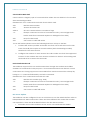
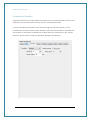
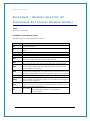
REVISION HISTORY
Product
Model
Document Type
Current Version Number
Status of the Document
Revision Date
Total Number of Pages
-
Intelimax M2M 3G Serial Modem
MA-2015
PDF
8.0
Release
September 2015
95
Revision History
Level
1.0
5.0
7.2
7.3
Date
7.4
October 2013
7.5
7.6
7.7
April 2014
May 2014
October 2014
7.8
March 2015
7.9
8.0
June 2015
September 2015
May 2012
November 2012
July 2013
July 2013
History
Internal Draft Version
Stable Release Version
Stable Release Version
Added new AT commands
Added Modem Emulation, maXconnect, SMS on boot, SMS
Reboot in Serial mode
Updated AT commands
Updated FTP section and Invalid PPP password characters
Updated AT command section and E-die notice
Corrected the errors in LED Functionality Table
Added details of AT$$SPC command
Added PPP Server Functionality
Updated with SSLv3 socket
- 10 -
Intelimax User Manual
Intelimax USER MANUAL
All data and information contained in or disclosed by this document are confidential
and proprietary information of Maxon Australia, and all rights therein are expressly
reserved. By accepting this material, the recipient agrees that this material and the
information contained therein are held in confidence and in trust and will not be used,
copied, reproduced in whole or in part, nor its contents revealed in any manner to
others without the express written permission of Maxon Australia. This information
provided in this document is provided on an “as is” basis.
In no event will Maxon Australia be liable for any damages arising directly or indirectly
from any use of information contained in this document. Information in this document is
preliminary and subjected to change without any notice.
Disclaimers
Life support – This product is not designed for use in life support appliances or systems
where malfunction of these products can reasonably be expected to result in personal
injury.
Maxon Australia customers using or selling these products for use in such applications
do so at their own risk and agree to fully indemnify Maxon Australia for any damages
resulting from such application.
Right to make change - Maxon Australia reserves the right to make changes, without
notice, in the products, including circuits and software, described or contained herein
in order to improve design and/or performance.
Some features outlined in this manual may require an updated firmware version and/or
GUI version to work. Please contact Maxon Australia for more information.
- 11 -
Intelimax User Manual
INTRODUCTION
Overview
Breaking the industry benchmark, the top-of-the range Intelimax is a unique and
intelligent fusion of 3G capabilities with advanced functionality of a modem/router.
Intelimax Features
General Features
HSPA Wireless Module EM-820W (21Mbps downlink, 5.6Mbps uplink)
Supports Packet and Circuit Switched Data
RS232 connection
2 Way SMS
Remote SMS diagnostics & reset
Embedded TCP/IP, UDP/IP STACK
Rugged plastic casing for industrial use
Save and restore modem configuration from a file
FOTA - Firmware upgrade over the air
External antenna connectivity to maximise HSPA coverage
External LED to show Network and Connection status
Extended Features
Remote CSD to IP Changeover
AT over IP
FTP Client
Programmable WAN connection scheduler
SSH and Telnet support
RSSI Logging
Configurable ping checking function
Backoff, variable periodic resets and other network friendly features
SNMPv2 and SNMPv3
SNTP
Modem Emulation
Dynamic DNS
PPP Server
Security Features
Encrypted access and configuration control
- 12 -
Intelimax User Manual
Password Protected AT Commands
SNMPv3 supports SHA and AES
SSLv3 Encrypted Serial Socket
Login brute force detection and rejection
Login activity log
Frequency Bands
WCDMA/HSPA 850MHz, 900MHz, 1900MHz, 2100MHz
GSM/GPRS/EDGE 850MHz, 900MHz, 1800MHz and 1900MHz
Data Speeds
HSPA:
UL 5.76 Mbps /DL 21 Mbps
WCDMA PS:
UL 384 Kbps / DL 384 Kbps
WCDMA CS:
UL 64 Kbps / DL 64 Kbps
GPRS/EDGE:
UL 236 Kbps / DL 236 Kbps
GSM CS:
UL 9.6 Kbps / DL 9.6 Kbps
Environmental Specifications
Normal Operation Temperature
Extreme Operation Temperature
-20 to 70° C
-25 to 75° C
Dimensions
71mm x 55mm x 26mm (without side brackets and antenna)
Connections
RJ45 Connection
USB Connection
SIM Card Holder
Antenna connector: FME male
Mounting
Side mounting brackets
LED Lights
Power
RSSI/ Data
Module Approvals
GCF
PTCRB
CE
FCC
ACA
Carrier Approvals* - (Please contact Maxon Australia for more information)
- 13 -
Intelimax User Manual
Modem Approvals
ACA
Compliance
RoHS Compliant
Power Source
DC Input Voltage Range: 6 to 32 VDC
Idle Current @ 12V: 50mA
Maximum Current @ 12V: 150mA
Operating Systems
Windows XP/ Vista / 7
- 14 -
Intelimax User Manual
Hardware compatibility
Intelimax hardware from October 2014 has been updated with a new flash memory
die, which is not compatible with older firmware revisions. Intelimax modems with this
memory die are clearly marked with an ‘E’ noting this change. Any modem with this ‘E’
marking can be used with firmware versions 2.0.x onwards. If older firmware versions are
loaded onto these modems will not run and will have to be returned to Maxon Australia
for recovery.
- 15 -
Intelimax User Manual
Intelimax Setup
Maxon Intelimax serial modem supports a Winodws GUI, where by you can configure
the modem via serial connection or remotely via the WAN IP.
Maxon recommends using the GUI connected via a TCP/IP connection in order to
utilise all the configuration settings. When connecting to the Intelimax using the GUI
when the modem is in serial modem mode, there will be very limited functionality.
After connecting to the modem using the GUI, users can configure; WAN settings,
Scheduler, IP Stack, SNMP Dynamic DNS and Admin settings.
- 16 -
Intelimax User Manual
Connecting to the Intelimax
TCP/IP Connection - Recommended
Using the TCP/IP connection option allows users to connect to the modem via an IP
connection. The modem must be connected to via TCP to perform firmware upgrades.
Local Connection
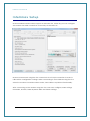
To use this feature locally you must follow the following steps:
1. Plug in modem RJ45 power/serial cable then mini USB cable in this order
2. Install USB/LAN drivers which can be downloaded from:
http://www.maxon.com.au/product-supports/drivers-and-manuals.html
3. Set a static IP address to the modem:
Once the drivers are installed you will have to set a static IP on the Intelimax
network connection (as the Intelimax does not support DHCP)
The default IP for the Intelimax is 192.168.10.1, set your IP within this range
Eg.192.168.10.50
4. Open the GUI to the modem (after modem has booted ~ 1-2 minutes)
The default settings are: Address: 192.168.10.1 (Intelimax LAN IP address), Port:
10918, ID: admin, Password: admin
Note : Power via USB doesn’t work in MA-2015, please use MA-2015S with Diode enable
modem in order to power via USB
- 17 -
Intelimax User Manual
Remote Connection
Users can also access the Intelimax remotely via a static IP address (e.g. maXwan) or
via a url (e.g. DynDNS)
Serial Port Connection
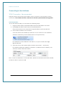
Use this section to connect to the modem using the provided RJ45 power/serial cable,
the default connection settings are:
Baud Rate:
115200
Databit:
8 bit
Parity:
None
Stop bit:
1 bit
Flow control:
None
Make sure to select the correct COM port and click the open button, the Intelimax GUI
will connect to the modem via the selected COM port. The GUI can also perform a
search for the correct baud rate if it is not known.
The configuration operations available over a serial connection to the modem are
limited when compared to a TCP/IP connection.
- 18 -
Intelimax User Manual
GUI Connection Debugging
1. What if I don’t know the serial interface to the modem?
The modem has a default baud rate of 115200, if you are not able to connect via the
serial interface at any baud rate, then restore the modem to factory defaults by
holding down the reset button for more than 20 seconds (5 second hold is for profile
reset).
2. Why does the Intelimax GUI not connect and reports “The attempt to connect was
forcefully rejected”?
If the Intelimax GUI connection to the modem is not closed with a TCP disconnect the
modem may reject connections and report with a message “The attempt to connect
was forcefully rejected”. This occurs until the modem TCP timeout occurs which will be
either via a modem reboot or after at least 10 minutes. If the connection is local you
can shorten this time by reconnecting the USB interface or under network connections,
selecting the LAN interface to the modem, disabling, then enabling this interface.
3. Why does the Intelimax GUI show that the device is discovered but not connect?
The LAN interface to the modem needs to be configured correctly. This may involve
setting a static IP address to the modem, such as 192.168.10.50 or removing an
incorrect address. The GUI will continue to try to connect to the modem 3 times after
the ‘Open’ button is pressed.
4. Why is the GUI not detecting the Intelimax?
The Intelimax must be powered via the RJ45 connector, then the USB plugged in, after
approximately 1 minute, the PC will prompt for drivers to be installed. The Intelimax
requires the USB/LAN interface drivers installed to be able to talk via a TCP IP
connection to the modem, which can be downloaded from the Maxon website.
There are times where the RNDIS network interface is present under network
connections but not when checked via a command line (ipconfig). If this is the case
then the PC must be restarted as the Microsoft Windows RNDIS driver is not functioning
correctly.
- 19 -
Intelimax User Manual
Modem Configuration
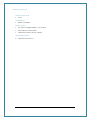
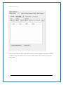
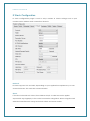
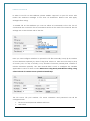
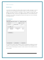
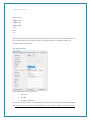
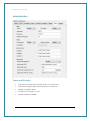
Modem Status Tab
The modem status page displays modem information such as network registration and
WAN connectivity status.
Information displayed on the Status page is:
F/W Revision: Firmware version output. Includes version and compile date. Ex 0.0.0
[201201061408]
H/W Version:
Product’s board release version
Module F/W Revision: Engine’s firmware version
LAI:
LAC, Cell ID,
IMEI:
IMEI number of the Intelimax
WAN IP:
IP address assigned by ISP such as Telstra or Optus
Signal:
Status of current signal strength (dBm)
IP Stack Mode:
IP Stack Mode of Intelimax. (IP Stack Auto or Manual)
PIN Status:
Status of PIN request (enable/disable)
System Time:
System time acquired 3G network
- 20 -
Intelimax User Manual
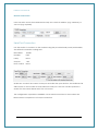
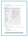
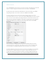
WAN Configuration
WAN configuration page is used to configure how the modem will connect to the 3G
network. Please select the correct operation mode as this will decide if the modem will
automatically connect to the network on power up or work in pass through mode.
The Intelimax supports 6 operation modes:
1. IP Stack Auto mode: Modem connects to the 3G networks and acquires an IP
address and then runs the IP STACK server or client mode.
2. IP Stack Manual mode: Modem wait for user to send AT commands before
connecting to the 3G networks and acquiring an IP address.
3. Serial mode (Pass-through/Transparent): Connects to the 3G module in the
modem. Used for PPP pass-through or Circuit Switched Data (CSD).
4. PPP WAN Auto mode: Modem is a PPP server over serial with the WAN IP
connection automatically connected.
5. PPP WAN Conditional mode: Modem acts as PPP server with the WAN IP
connection conditional on the serial PPP connection.
6. PPP WAN Manual mode: Modem acts as PPP server and the WAN IP connection
can be controlled via AT over IP commands.
- 21 -
Intelimax User Manual
IP Stack Auto Mode
When using IP STACK Auto the modem will behave as an IP Serial modem. When using
this mode the modem will transfer all incoming packets via the serial port to the host
and vice versa. The modem connects to the 3G networks and acquires an IP address
and then runs the IP STACK server or client mode.
Intelimax IP Stack can be configured as a Server or Client mode. In Server mode the
Intelimax will act as a socket server. The modem will listen on a specific TCP/UDP port
waiting for an incoming client socket connection. As soon as the client drops the socket
connection, the Intelimax will go back to socket listening mode as per IP stack
configuration. On the other hand with client mode the Intelimax will try to establish a
socket connection to a preconfigured server IP address or DNS name and port number.
The client mode also supports a secondary server IP address just in case the primary
server cannot be reached. The in-built IP stack feature supports smarts such as PPP link
check, TCP link check, PPP link timeout, TCP link timeout and MTU settings.
Secure socket using SSLv3 can be used in both these modes as well as IP Stack Manual
Mode. Further detail on how to configure secure socket is in the IP Stack tab section.
IP Stack Manual Mode
With IPStack manual mode, the modem doesn’t initiate the PPP connection. The
modem will rely on the host on serial port to send the PPP initiation commands and
acquire a WAN IP connection.
The AT command to start the PPP session and open a socket is AT$$IPCTOS.
The AT command to close the socket and PPP session is AT$$IPCTCS.
Further AT command detail is included at the end of this manual.
Serial Modem Mode (Transparent / Pass-through)
This mode allows for the serial interface to connect through to the 3G module in the
modem. In this mode the Intelimax processor still has some control and processing
abilities over the serial AT commands and connection processes. Used for PPP passthrough or Circuit Switched Data (CSD).
- 22 -
Intelimax User Manual
Circuit Switch Data Call
Circuit switch is a legacy style of communication where the user dials in to the modem
data terminating number.
Standard set of AT commands used with Circuit Switch Call:
ATD
Dial the Data number
ATA
Answer the Data Call
ATS0=n
Set auto answer where n=number of rings
+++
Escape command to enter AT command mode (1 second gap both
before and after command required to distinguish from data)
ATH
Drops the data call
ATO
Can return to call if still active
To use this feature please ensure the following has been setup on the SIM:
1. Contact SIM service provider and make sure that CSD is activated on the Sim
card. Generally this requires a second number (data terminating number)
attached to the same service.
2. Configure the modem to auto answer the call or make sure that the equipment
connect to the modem has auto answer activated to detect an incoming call
and sends ATA to answer the data call.
Packet Switch Data Call
The Intelimax supports PPP over serial connections through the modem and utilizes
standard AT commands for this purpose. It is recommended that user dial out control
code executes a hang up process command before each reconnection attempt by
issuing a +++ command followed by and ATH command.
Standard set of AT commands used with PPP call:
ATD
Dial the PPP number (e.g. *99#)
+++
Escape command to enter AT command mode (1 second gap both
before and after command required to distinguish from data)
ATH
Drops the data call
ATO
Can return to call if still active
PPP Server Options
The Intelimax can be configured to act as a PPP Server over the serial interface with an
independent PPP WAN connection. There are three different PPP modes the modem
can operate in, these are all outlined further in the PPP Server section:
1. PPP WAN Auto mode: Modem is a PPP server over serial with the WAN IP
- 23 -
Intelimax User Manual
connection automatically connected.
2. PPP WAN Conditional mode: Modem acts as PPP server with the WAN IP
connection conditional on the serial PPP connection.
3. PPP WAN Manual mode: Modem acts as PPP server and the WAN IP connection
can be controlled via AT over IP commands.
Invalid PPP password characters list:
“(double quotation mark)
‘(quotation mark)
?(question mark)
)(bracket)
@(at sign)
;(semi colon)
|(pipe sign)
I(upper case I)
Band Change
When band changing two reboots are required. The first reboot will save the setting to
the module and second reboot will apply the changes to the module so that module
will register to the selected band.
Only bands which are supported by the module will be displayed in this section.
Users can change bands in serial modem mode via Intelimax GUI with the firmware
0.1.56 or later. When band changing two reboots are required. The first reboot will save
the setting to the module and second reboot will apply the changes to the module so
that module will register to the selected band.
For GSM 900
The user has to tick all GSM 900 bands to be able to connect to the GSM 900 band.
Double reboot is required.
- 24 -
Intelimax User Manual
For UMTS 850
The user will be able to lock to UMTS 850 network by just ticking the UMTS 850 band in
the GUI. Double reboot is required.
WAN page allows configuring the following features:
APN and dialup string
Username and password for IP WAN
Auto pin settings (Intelimax will enter the PIN code if SIM pin is Enabled)
Network authentication information
Watchdog (Ping Function)
Back off timer
Periodic reset
o
Can be enabled or disabled
o
Configurable by number of hours between 1 and 28
Reset state setting. Reset will happen in any state unless configured otherwise
by:
o
TCP Server Listening – For use in IP Stack Auto Server mode – If checked
will wait until TCP connection is dropped by either server or client before
performing the reset.
o
TCP Connection State – For use in IP Stack Auto Client mode – If
checked will wait until Intelimax client drops connection to a server or
server drops connection before performing the reset.
Battery
o
When ticked, modem will enter idle mode (cellular module and serial
port are switched off) when battery voltage is below 11.9V. Modem will
be back to normal after battery voltage is over 12.3V.
- 25 -
Intelimax User Manual
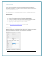
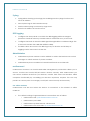
Scheduler
The scheduler tab allows configuring modem WAN connection schedule. The scheduler
supports two methods of selection. Days of the Week (setup to come on certain days of
the week) or Setting up a certain power up duration (setup to come certain during the
hour).
Scheduler Day of the Week:
Using this option the user can specify days of the week when the modem will connect
to the internet and would be online. The connection and disconnection time is in 24
hour format. While using the scheduler the RS232 and the 3G module can also be
configured to shutdown to save power.
To setup Scheduler by Day of the week, select the Day with the connect and
disconnect times. You can also set the modem to power off itself when it disconnects,
by checking the power off check box.
To delete an entry click on the entry and press the Remove selected Item button, or if
you want to remove all entered entries click the “Remove ALL” button.
- 26 -
Intelimax User Manual
In the above example the modem will connect on Sunday 6:30AM and will disconnect
at 5:30Pm and power itself off, this feature is really handy if the modem is running on
solar power.
- 27 -
Intelimax User Manual
Scheduler by Duration
Using this method the modem will be powered up for a certain duration, then power
itself down for another period of time, and the cycle repeats itself.
To setup scheduler by duration enter for how long you wish the modem to stay
powered up and enter power cycle duration. The power down will be calculated by
the modem. In the below example the modem will stay powered for 5 min, power
down for 25 min and the cycle is repeated. (Range 0~60 minutes)
- 28 -
Intelimax User Manual
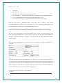
Serial Configuration
The Serial configuration page is used to setup modem serial settings such as baud rate,
serial messages, and SMS on boot.
Serial Port Setup:
Serial port setup includes the following
Baud rate (the modem supports 1200, 2400, 4800, 9600, 19200, 38400, 57600 and
115200)
Data Bit (7Bit or 8bit)
Stop bit (1bit or 2bit)
Flow Control (None, Software or Hardware)
&D, S0, &C, Echo and Q
- 29 -
Intelimax User Manual
Serial port speed setup should be set to match host (connected via serial port)
configuration. With certain applications there may be a need to fabricate a custom
serial cable to work between the host and the Intelimax. The custom serial cable
depends on the equipment requirements and settings.
Serial Password – Password protected AT commands
The Intelimax has the ability to password protect serial interface AT commands. The
serial password can be set on the serial tab. If AT commands need to be entered then
AT commands will return an ERROR message until the interface password is entered first
with the command, AT$$PWD=<password>. Once the password is entered the access
will persist for the session until the modem reboots. Further AT command detail in the AT
Command Password Protection section under the Intelimax specific AT Commands
section.
Boot up Message
The Intelimax boot up message “INTELIMAX READY” is a message that the modem sends
to the host via serial port upon boot up. Using this option the user can disable or enable
this message.
- 30 -
Intelimax User Manual
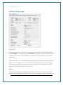
IP Stack Configuration
IP stack configuration page is used to setup modem IP STACK settings such as port
number and IP address and connection timeouts.
Protocol:
IP Stack supports TCP and UDP, depending on your application requirement you can
choose between TCP and UDP communication
SSLv3:
If the SSLv3 check box is ticked, the Intelimax TCP/IP to serial converter applies
asymmetric cryptography to the socket connection using SSLv3. When using SSLv3 all
serial data transferred is encrypted in both client and server modes.
- 31 -
Intelimax User Manual
The SSLv3 certificates can be installed using the partial upload function in the GUI using
the following process:
1. Create the certification file for upload to the Intelimax. The certificate files
should be placed into a folder along with a path.txt file.
2. The path .txt file should only contain the text “extra”.
3. Zip this folder, then upload to the Intelimax using the ‘Partial upload’ button in
the GUI, then reboot the modem.
4. Once the modem has rebooted the uploaded certificates can be seen on the
status page under the ‘Extra’ section.
Note: To remove the certificates, upload a .zip file with one file, a path.txt file with the
text “-extra”.
Note: If both SSLv3 IP Stack and secure syslog is used at the same time then the same
private key and certificate are used (the ca.pem certification file is not used by SSLv3).
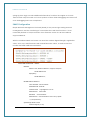
How to generate SSL certificates:
A SSL certificate can be generated using an application such as OpenSSL
(http://slproweb.com/products/Win32OpenSSL.html, the lite version is fine).
To generate certificate for client and key for client (key.pem, cert.pem):
C:\OpenSSL-Win32\bin>openssl req -new -x509 -days 3650 -nodes -config openssl.cfg out cert.pem -keyout key.pem
This application can be run from the command line for example: C:\OpenSSLWin32\bin>openssl req -new -x509 -days 365 -nodes -config openssl.cfg -out cert.pem keyout key.pem.
The resultant 2 certificate files contained in the /bin folder and are named: cert.pem
- 32 -
Intelimax User Manual
and key.pem.
Mode:
Intelimax supports operation of the IP Stack in either client or server modes:
Server mode: In Server mode the modem will connect to a PPP session and will
listen on a predefined port for incoming client requests
Client mode: the modem will initiate a PPP connection and try to connect to
the Primary server. If the connection to the server fails 10 times it will try the
Secondary server, if the connection to the secondary server also fails for 10 times
the modem will drop the PPP connection, reboot and start all over again.
Primary Server
Define the IP Address or DNS address of the primary server the Intelimax will try to
connect to in Client mode, in server mode please leave this field as default.
Secondary Server
Define the IP Address or DNS name of the secondary server the Intelimax will try to
connect to in Client mode, in server mode please leave this field as default.
Port Number
Define the TCP or UDP Port number, this port will be used in the server and client mode.
IP STACK Notifications
IP Stack notifications are by default sent out on the serial port to the connected host.
With some applications this may cause issues with data transfer and using this option
the user can disable or enable the notification messages.
Idle Timeout / Idle Timer
Enabling the idle Timeout and setting an Idle Timer, will set the Intelimax to disconnect
from a connected server (if configured as a client) or the connection from a
connected client (if configured as a server) if the modem receives no data for the
defined Idle Time period. Bear in mind that data could be continuously sent from the
modem to the connected device, but if nothing is received back, the modem will
disconnect. If the modem is connected as an auto-connect client then it will try to
reconnect to the server once it has disconnected.
- 33 -
Intelimax User Manual
TCP Connect Message
The TCP connect message function allows for sending either a custom string or the IMEI
number over the socket connection when it is established. If the field is left blank then
the IMEI number of the modem will be sent, otherwise the custom message, up to 32
characters.
UDP Session Control
To enhance the reliability of UDP IP Stack communication within the Intelimax, we have
introduced a new configuration option, which provides Intelimax users with more
control over the UDP activity and data communication. The user can now enable or
disable keep alive in conjunction with the Network Dormant period or alternatively
specify Wake up time in seconds.
Wake up feature will send dummy UDP packets prior to sending any data received via
serial port to setup a channel with the network. The modem will send dummy packet
twice as per timing set, followed by the actual data. This is to ensure the UDP data is not
lost.
Network Dormant Period: By default the network puts the modem in dormant or
standby mode within 20 seconds of no data activity.
Keep Alive: This sends a dummy UDP packet prior to modem going dormant and this is
based on the Network Dormant Period, This packet will be sent only if the modem
doesn’t send any data over the wireless network for the Network Dormant period.
Wake Up: Wake up feature will send dummy UDP packets prior to actual data, this
wakes up the communication channel and guaranties sending the complete UDP data
packet to the receiving end. Enabling this could lead to additional delay in data
transfer due to modem sending a dummy packet first to initialize the UDP connection
with remote site.
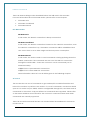
FTP
The FTP functionality on the Intelimax allows for logging and uploading serial streams of
data. A new line in the file is created each second and a timestamp can either be
enabled or disabled.
- 34 -
Intelimax User Manual
In order to use FTP on the Intelimax, please enable ‘append’ on your FTP server. Also
restrict the welcome message to less than 10 characters. Please save and apply
settings before using.
To enable FTP on the Intelimax you can use either AT commands or the GUI, the AT
commands are covered in the AT command section at the end of the manual. The FTP
settings are on the IP Stack tab of the GUI.
Here you can configure whether to upload the FTP files manually, hourly (0-24, number
of hours between uploads), by time of day (0-24, where 1 is 1AM and 13 is 1PM), by day
of month (1-31, for day of month), or by number of minutes passed (0-60, number of
minutes between uploads). The time interval field is used to configure the variable
applicable to each of these modes. NOTE: when using Hourly and Minutes setting, using
a time interval of 0 means never upload automatically!
The FTP server, FTP port number, FTP server username and password can all be
configured here.
FTP Sever Host IP/Domain address with Port
User name
- 35 -
Intelimax User Manual
Password
Time interval
Header of file name (limit 10 bytes/characters)
Size of file (Bytes) – maximum 102,400 bytes, maximum internal buffer size 10MB
A new file will be created each time the file size is exceeded.
Time stamp – enable (1) or disable (0) timestamp prefix (in seconds)
Each file will have a standard prefix used here with a suffix in the format
DDMMYYYHHMMSS, where D is day, M is month, Y is year, H is hour in 24 hour format, M is
minutes, and S is seconds. E.g. DHMAX10102014181146.csv.
A reboot is required when enabling, disabling or making changes to the FTP options.
The "size of file" parameter is used for limiting the file size of the csv file. All the input from
serial port will be saved in the .csv file, and once the file size of that csv file exceed the
size limit, another file will be created to hold the input. The value allowed is 1000 100*1000 Bytes.
Based on the configuration, the file could be uploaded to server periodically. For
example:
With these settings, the modem will send a .csv file to the FTP server every 30 minutes. If
the input has not exceeded limit 10K bytes (in this case), modem will send this file only,
then generate another file for holding future input. If the input is more than 10K bytes,
there should be more than one file generated, each file should not exceed 10K bytes,
all these files will be sent to FTP server when time comes.
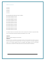
File uploaded with date time stamp disabled:
AT+CSQ
- 36 -
Intelimax User Manual
AT+CSQ
AT+CSQ
AT+CSQ
AT+CSQ
AT+CSQ
File uploaded with date time stamp enabled:
09/11/2012 15:44:05 AT+CSQ
09/11/2012 15:44:06 AT+CSQ
09/11/2012 15:44:07 AT+CSQ
09/11/2012 15:44:08 AT+CSQ
09/11/2012 15:44:09 AT+CSQ
09/11/2012 15:44:10 AT+CSQ
09/11/2012 15:44:11 AT+CSQ
09/11/2012 15:44:12 AT+CSQ
09/11/2012 15:44:13 AT+CSQ
09/11/2012 15:44:14 AT+CSQ
09/11/2012 15:44:15 AT+CSQ
In manual mode AT commands can be used to prompt the modem to upload the files,
the AT commands themselves will also be included in the .csv file.
AT$$FTPFL
Displays the files waiting to be uploaded
AT$$FTPSC
Will start the FTP connection and upload the files. This command can also be used to
force an upload when in periodic mode. If no WAN connection is currently established
(such as in IP Stack Manual mode) the Intelimax will establish the PPP and socket
connections, upload the FTP files then drop the socket and PPP connections.
- 37 -
Intelimax User Manual
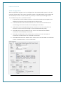
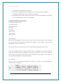
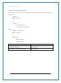
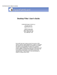
Modem Emulation TAB
Description
Modem emulation assists in the transition from Circuit Switched Data (CSD) to Packet
Switched Data/IP (PSD). If the control centre management system supports IP but the
field devices only support dialling back to the control centre using CSD, then you can
use the Intelimax to emulate the CSD modem interface. The Intelimax can also be
configured to act as an IP stack server for incoming connections if necessary.
IP
Connection
CSD
Emulation
Cellular Network
Internet
Field device
Intelimax
172.16.0.1
Server 10.0.0.1
Dialing Process
From the perspective of the field device it will dial out a CSD data call like it always has,
except the Intelimax will instead establish an IP stack client connection to the server. For
example the field equipment may dial the following string: ‘ATDT0412123456’, then wait
for the connection to be established by receiving a ‘CONNECT’ message. The Intelimax
can be configured to establish an IP stack client connection to one of several different
server IP addresses depending on the number dialled.
Intelimax Configuration
The Intelimax must be configured in IP stack auto server or IP stack manual server
mode. This configuration can be made using the Intelimax GUI or via AT commands. If
the Intelimax is in IP stack manual mode then it will only connect to the network when it
receives the ATDT command via serial and will drop the connection when the call is
hung up (+++, ATH). If the Intelimax is in IP stack auto mode (server) then it will act as an
IP stack server (and therefore could be addressed remotely) until it receives the dial out
commands.
- 38 -
Intelimax User Manual
RING Message
To emulate the incoming CSD call the Intelimax will print out RING messages at a rate of
1 RING per second according the S0 setting. In order to account for this delay when
dialling out through the modem it is advisable to add a CONNECT message delay using
the AT$$TCPDEL=<MS> command, e.g. AT$$TCPDEL=2000 for a 2 second delay before
printing out the CONNECT message (this command can only be set via AT commands,
not through the GUI).
GUI Configuration
Up to 40 phone numbers can be added to match to destination IP addresses and port
numbers. It is recommended that 5-10 numbers are added at a time through the GUI
before saving and rebooting the modem to reduce the risk of GUI connection timeout
and lost entries.
- 39 -
Intelimax User Manual
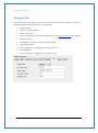
Dynamic DNS
Allows the user to configure; Username, Password and Domain name to be used by
Intelimax when authenticating on a DDNS server.
Enable DDNS
Select to enable DDNS.
Service Provider
Link of the DDNS service web page (Server site is http://dyn.com) by default)
Domain Name
Set DDNS host name or Alias from DDNS server
User Name/Email
Input User Name for logging onto a DDNS server
Password/Key
Input Password for logging onto a DDNS server
- 40 -
Intelimax User Manual
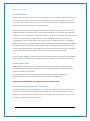
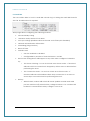
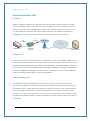
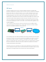
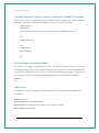
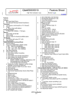
PPP Server
Usually the Intelimax acts as an IP connected cellular serial server, relaying data
between its serial inputs to TCP/UDP sockets. Devices connect to serial port of Intelimax,
directly send data or use dial commands to set up a data transmission session. Some
devices may need to use their own TCP/IP stack, in which case either serial modem
mode (transparent) or PPP server can be used. The benefit of using PPP server over
serial modem or transparent mode is that the modem functionality can continue to be
used and it will be uniquely addressed within the system. This allows for the use of AT
over IP for sending and receiving SMS messages or querying the signal strength, SNMP
for remotely monitoring the status of the modem, or remote firmware upgrades to the
modem if required.
* PPP, or Point-to-Point Protocol, is a protocol commonly used to establish a direct
connection between two devices over a serial cable, phone line, trunk line, cellular
telephone, specialized radio links, or fibre optic links.
Gateway
WAN PPP Conn
LAN PPP Conn
3G/4G Network
Serial
3G connection
In this working mode, the Intelimax will launch a PPP server and wait for the user device
PPP client to connect. Once the PPP connection is established, the device can talk to
the Intelimax through a network connection. The Intelimax then acts like a network
gateway, all data traffic from the device will be routed to the WAN interface, and then
be sent to the internet. In all PPP server modes, traffic from end-device to internet is
masqueraded behind modem WAN IP.
The device can use any TCP/UDP port to talk to peer applications on the internet side,
thus the dedicated TCP/UDP socket connection between the Intelimax and user server
application is no longer needed, the user device can open socket directly.
- 41 -
Intelimax User Manual
There are WAN working modes described below that will work in this scenario:
For more information about PPP WAN modes, please refer to next chapter.
PPP WAN Auto
PPP WAN Conditional
PPP WAN Manual
PPP WAN modes
PPP WAN Auto
In this mode, the WAN IP connection is always connected.
PPP WAN Conditional
In this mode, the WAN IP connection is based on the LAN PPP connection, once
the LAN PPP connection is up, the WAN IP connection will be established and
vice versa. This is to save data usage and device power consumption.
PPP WAN Manual
In this mode, the device needs to send commands to bring up/bring down the
WAN IP connection. The command are sent over the LAN PPP connection
through the serial cable – these are custom AT over IP commands (not to
internal module).
AT$$IPCTOP to open WAN PPP connection.
AT$$IPCTCP to close WAN PPP connection.
More information about AT over IP will be given in the following chapter.
AT over IP
The user device can use AT commands to get modem/3G module information and
instruct the modem to perform some actions. To use AT commands, user device should
open a TCP socket on port 12522, which is configurable through GUI, and then send AT
commands to this socket. Only pre-defined AT commands are supported. Please refer
to the Maxon Intelimax user manual for the custom AT command format and which
commands are currently supported.
There are several commands that are not needed when the Intelimax is in PPP server
mode such as:
- 42 -
Intelimax User Manual
ATD or ATDT
AT$$IPCTOS
AT$$IPCTCS
AT$$TCPDEL
ATH
ATO
+++
All socket related commands are not supported because when the Intelimax works in
PPP server mode, the TCP/UDP socket on the WAN side is no longer needed, the
modem now is a gateway.
PPP Dialing Modes
Three Dial modes are supported:
MS Chat
No Dial
Modem Emulation
The MS Chat Dial mode is to support Microsoft Windows PPP client. Before initiating the
PPP connection, it requires the exchange of the text strings “CLIENT” (from the client)
- 43 -
Intelimax User Manual
and “CLIENTSERVER” (from the serer). So in MS Chat mode, the Intelimax PPP server will
expect a “CLIENT” string from the client and then send back “CLIENTSERVER”.
No Dial mode means the client PPP will initiate PPP connection without any dialing
string being sent prior to PPP session. THIS IS NOT CURRENTLY SUPPORTED
In Modem Emulation mode, the PPP client will send dialing strings such as ATV1;
AT+CGATT=0;ATDT*99***1# etc., and user can define dialing strings to be sent to the PPP
server. The user can also define what string it will expect to hear back from PPP server
before the PPP connection is initiated. In this mode, two fields need to be configured
through the Intelimax GUI, to make PPP server answer client device accordingly.
All AT commands for dialing should be sent before the dialup String, the special
command ATDT*99***1# will inform the Intelimax to go into a PPP exchange string
mode, listening to the dialing string defined after the ATDT*99***1# command.
In Modem Emulation mode, before the PPP connection is established, AT commands
are supported to change settings in the modem or collect information from the
modem. All standard AT commands and Maxon customized AT$$ commands are
supported. The command ATDT*99***1# is to notify the Intelimax to go into the PPP
- 44 -
Intelimax User Manual
mode, after this command no more AT commands are supported through direct
accessing of the serial port. To continue to use AT commands after PPP connection, AT
over IP to port 12522 can be used.
The dialup string such as “cr1000dial” should be entered in the dialup strings section.
Other PPP Options
ACCM: Async-Control-Character-Map enable or disable
PComp: Protocol field compression negotiation enable or disable
VJ comp: Van Jacobson style TCP/IP header compression enable or disable
Proxy ARP: Proxy Address Resolution Protocol enable or disable
Magic: Magic Number Negotiation enable or disable
Please see https://ppp.samba.org/pppd.html for further detail.
Authentication:
PPP server supports 3 authentication modes: None, CHAP and PAP.
Whenever CHAP or PAP authentication mode is selected, the username and password
should be provided as well, otherwise, these two fields can be left blank.
- 45 -
Intelimax User Manual
MRU:
Maximum Receive Unit. The PPP server will ask the client to send packets of no more
than [MRU] bytes. The value must be between 128 and 16384; the default is 1500.
Idle Timeout:
This is to specify that PPP server should disconnect if the PPP link is idle (No data traffic)
for [Idle] seconds.
Port Forwarding
The ‘Forward’ section is for entering the port forwarding options with the following
format:
Incoming port WAN : Outgoing port LAN
e.g. 8080:80 port 8080 on the WAN interface is forwarded to port 80 on the LAN
interface.
Extra port forwards are separated with a comma. Currently only individual ports can be
forwarded, but port ranges will be added.
An additional white paper on PPP server functionality is available from Maxon.
- 46 -
Intelimax User Manual
Administration
Telnet and SSH login
User Name setting using for Telnet and TCP connection.
Password setting using for Telnet and TCP connection.
Enable or disable Telnet.
Set Telnet port number to use.
Set SSH enable or disable.
- 47 -
Intelimax User Manual
Syslog
Syslog allows viewing system logs plus enabling remote syslogs function and
server IP address.
Save System logs in the internal memory.
Send modem Syslog to external sys logs server.
Enter the IP address of remote server.
RSSI logging
Configure the time period over which the RSSI logging will be averaged
(between 5 and 60 minutes). The RSSI value is measured every 10 seconds.
Configure the level at which the RSSI signal strength will be considered high. This
is the level at which the PWR LED will flash solidly.
The RSSI values are saved to the RSSI log every 15 minutes and 90 days of
logging can be recovered via the GUI.
Administrators
Administrator phone numbers can be added to restrict the SMS remote control
messages to a limit number of phone numbers.
Administrators phone numbers in international format +61412 345 678
maXconnect
maXconnect is Maxon’s a cloud based M2M management portal which allows you to
access, monitor and control 3G/4G Maxon devices securely. With maXconnect you
can access real-time data from your devices, monitor their status and location. Utilise
complete functionality by controlling your devices anywhere, anytime. This one stop
portal is an access point to manage your 3G/4G assets securely and remotely.
Use within maXwan
maXconnect can be used when the device is connected to the Internet or within
maXwan.
The default settings for general internet connections are as follows:
o
maXconnect URL: portal.maxconnect.com.au
o
maXconnect port: 1883
o
maXconnect update interval: 120 seconds
o
maXconnect FTP server URL: ftp.maxconnect.com.au
- 48 -
Intelimax User Manual
For connections to MaxConnect within MaxWAN please use the following:
o
maXconnect URL: 10.0.0.1
o
maXconnect port: 1883
o
maXconnect update interval: 120 seconds
o
maXconnect FTP server URL: 10.0.0.32
- 49 -
Intelimax User Manual
System settings page
AT over IP
AT over IP can be used to access the AT command interface of the Intelimax internal
cellular module or the Intelimax specific modem AT commands. The AT over IP function
can be used either over the local USB/LAN interface to the modem or via a remote IP
connection.
This can be useful for remotely checking signal strength, sending SMS messages through
the modem etc. While the AT over IP connection to the module is in use the modem
cannot communicate via AT commands to the module so it is recommended to only
open the port for less than a minute at a time.
Debug
The debug settings allow for additional debug levels to be set in the modem to allow
for additional debugging capabilities. When these debugging settings are enabled, the
- 50 -
Intelimax User Manual
syslogs (system logs) contain additional information for either the engine or IP stack.
These should only be turned on for short periods of time while debugging and turned off
once debugging has been completed.
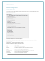
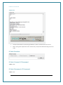
SNMP Configuration
Simple Network Management Protocol (SNMP) is the protocol governing network
management and the monitoring of network devices and their functions. It is not
necessarily limited to TCP/IP networks. From firmware version 0.1.56 the Intelimax
supports SNMPv3.
With the Intelimax SNMP customers can read the modem Signal Strength, registration
value, ecio, rscp, IMEI, firmware and module firmware values, as well as reset the
modem via SNMP MIB as shown below.
MAXON-MIB DEFINITIONS ::= BEGIN
IMPORTS
OBJECT-TYPE, MODULE-IDENTITY, Integer32, enterprises
FROM SNMPv2-SMI
DisplayString
FROM SNMPv2-TC;
MaxMIB MODULE-IDENTITY
LAST-UPDATED "201104150000Z"
ORGANIZATION "DHPLAB"
CONTACT-INFO
DESCRIPTION
REVISION
"support@maxon.com.au"
"Maxon MIB"
"201104150000Z"
DESCRIPTION "This file defines the maxon mib by dhplab."
::= { enterprises 0910 }
signalStrength OBJECT-TYPE
SYNTAX Integer32 (0..105)
- 51 -
Intelimax User Manual
MAX-ACCESS read-only
STATUS current
DESCRIPTION
"Signal strength of the modem"
::= { MaxMIB 1}
registrationValue OBJECT-TYPE
SYNTAX Integer32 (0..5)
MAX-ACCESS read-only
STATUS current
DESCRIPTION
"Registration of the modem"
::= { MaxMIB 2}
ecioValue OBJECT-TYPE
SYNTAX DisplayString
MAX-ACCESS read-only
STATUS current
DESCRIPTION
"EC/IO of the modem"
::= { MaxMIB 3}
rscp OBJECT-TYPE
SYNTAX DisplayString
MAX-ACCESS read-only
STATUS current
DESCRIPTION
"RSCP of the modem"
::= { MaxMIB 4}
imei OBJECT-TYPE
SYNTAX DisplayString
MAX-ACCESS read-only
STATUS current
DESCRIPTION
"IMEI of the modem"
::= { MaxMIB 5}
boardreset OBJECT-TYPE
SYNTAX Integer32 (0..1)
MAX-ACCESS read-write
- 52 -
Intelimax User Manual
STATUS current
DESCRIPTION
"Board reset"
::= { MaxMIB 6}
firmware OBJECT-TYPE
SYNTAX DisplayString
MAX-ACCESS read-only
STATUS current
DESCRIPTION
"Firmware version of modem"
::= { MaxMIB 7}
firmwareModule OBJECT-TYPE
SYNTAX DisplayString
MAX-ACCESS read-only
STATUS current
DESCRIPTION
"Firmware version of module"
::= { MaxMIB 8}
END
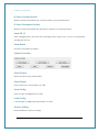
SNTP
SNTP can be used to update the time of the Intelimax. The modem will by default take
its time from the network. When SNTP is enabled, the modem will query a networkbased NTP server using the SNTP protocol and pull the time from it. The timezone can be
configured depending on where in the world the modem is used. If the daylight savings
setting is configured the modem will add an additional 1 hour to the system time
setting. If SNTP is not configured correctly or the server is not available then it can cause
the system logs to incorrectly record as they are referenced to system time. The minutes
configuration can only be set to 30 minutes.
- 53 -
Intelimax User Manual
Output Info
Output Information for receiving Intelimax’s data in serial or remote access.
When syslog are requested, this is where they are printed before being saved to
a file.
IP Stack Functions
IP Stack Connect AT Command
AT$$IPCTOS
IP Stack Disconnect AT Command
AT$$IPCTCS
- 54 -
Intelimax User Manual
IP Stack Connect Button
When IP Stack is Manual Mode, connect without AT Command input.
IP Stack Disconnect Button
When IP Stack is Manual Mode, disconnect without AT Command input.
Send CR, LF
Add Carriage Return and Line Feed message when data is sent. Use for AT Command
sending via the GUI.
Send Button
Send AT Command and Data.
System Functions
Clear Output
Delete modem output information.
Save Output
Save Output Info’s information as a File.
Save Config
Save modem configuration as a file.
Load Config
Load modem configuration information as a file.
Factory Setting
Reset Intelimax to factory settings.
- 55 -
Intelimax User Manual
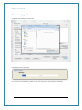
Firmware Upgrade
Upgrade the Intelimax’s firmware
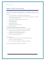
Click ‘Firmware Upgrade’ button and select firmware file. And open the file, the
uploading screen appears.
Do not remove Intelimax’s cable or turn off the power until upgrade finishing.
- 56 -
Intelimax User Manual
SMS Commands (IP modes)
The Intelimax can be used to send and receive SMS messages through standard SMS AT
commands with an internal buffer of 100 messages. In addition to this the Intelimax
supports a number of custom SMS messages for which can be used to check and
modify some settings remotely.
Following SMS commands can be used to change the APN, ID, Password,
Authentication and even rebooting Intelimax. Also after changing the APN, ID,
Password, Authentication, Intelimax will send a confirmation SMS after applying the
change.
Change APN (e.g. telstra.extranet)
SMS Syntax: INTELIMAX.PARK.APN telstra.extranet
Response: “APN set as <APN>”
Change Username, Password and Authentication (e.g. Username:
maxon@maxon.com.au, Password: maxon, Authentication: chap)
SMS Syntax: INTELIMAX.PARK.AUTH maxon@maxon.com.au:maxon:chap
Response:
“IP:<IP.IP.IP.IP>,APN:<APN>,ID:<ID>,PW:<PW>,Auth:<PAP,CHAP,BOTH>,Re
g:<0,1>,Sig:<CSQ>”
Check Settings and IP address
SMS Syntax: INTELIMAX.PARK.WANIP
Response:
“IP:<IP.IP.IP.IP>,APN:<APN>,ID:<ID>,PW:<PW>,Auth:<PAP,CHAP,BOTH>,Re
g:<0,1>,Sig:<CSQ>”
Reboot Intelimax
SMS Syntax: INTELIMAX.PARK.REBOOT
RSSI Info
SMS Syntax: INTELIMAX.PARK.RSSI
Response: “RSSI <RSSI in dBm>”, e.g. “RSSI -67”
- 57 -
Intelimax User Manual
DDNS configuration change by SMS
SMS Syntax:
INTELIMAX.PARK.DDNS1 <mode>(,<host address>)
INTELIMAX.PARK.DDNS2 <domain name>,<user id>,<user password>
SMS Commands (Serial modem modes)
The Reboot Intelimax SMS command can be used to act on Intelimax specific SMS
messages when in serial modem mode. For this to happen the modem must be told to
intercept the SMS messages using the AT$$STEALTHSMS command.
AT$$STEALTHSMS?
$$STEALTHSMS: 0
OK
AT$$STEALTHSMS=0 – disable modem interception of SMS messages
OK
AT$$STEALTHSMS=1 – modem to intercept SMS message
OK
Reboot Intelimax
SMS Syntax: INTELIMAX.PARK.REBOOT
RSSI Info
SMS Syntax: INTELIMAX.PARK.RSSI
Reply message syntax: RSSI <value> e.g. RSSI -57
Change mode via SMS
SMS Syntax:
INTELIMAX.PARK.CHGMODE <1(IPStack Auto)/2(IPStack Manual)/3(Serial Modem)>
e.g. INTELIMAX.PARK.CHGMODE 1
Reply message syntax: Mode Change To <mode>
e.g. Mode Change To IPStack Auto
The modem will automatically reboot after sending the response.
- 58 -
Intelimax User Manual
PROGRAM INTELIMAX VIA CIRCUIT CALL
The Intelimax has the unique in-built feature of being able to change between modes
and configure settings remotely over a CSD call. This is especially useful if you have a
modem in the field that you need to remotely configure using remote AT commands or
the Intelimax GUI but are currently using CSD to talk to this modem. Using these
commands lets you change to an IP connection for easy access to the device over an
IP connection. This feature is available from firmware versions 0.1.67 onwards.
It is very important to ensure that you can access your modem once this is done which
means either using a static IP address (private IP WAN or similar) or a public dynamic IP
address such as telstra.extranet the WAN IP of which can be found via SMS.
Dialing Process
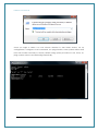
Dial out to the modem via a command line terminal session to your data modem using
the data number of the SIM card in the Intelimax. The sting will be as follows:
ATDT0400123456. Once the ‘CONNECT’ message has been displayed you are
connected.
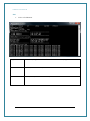
Intelimax Remote Configuration Commands
The following commands can be used to change the settings of the Intelimax:
Unlock the CSD programming interface: program.maxon.unlock=admin:admin
admin:admin are the default username and password, if you have changed these
update this command with the appropriate values in the order username:password.
Update the cellular APN: program.maxon.apn=telstra.extranet
Update the CPN username, password and authentication:
program.maxon.auth=userid:password:chap/pap/none
Change the mode of the modem: program.maxon.mode=1
Where:
IP Stack Auto mode – auto connect IP
IP Stack Manual mode – manual connect IP
Serial modem mode – for CSD or when end device controls connection
- 59 -
Intelimax User Manual
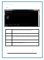
Apply all the settings and reboot: program.maxon.lock
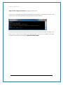
Once the commands have been received by the modem it will display ‘Modem will
reboot now’ and the call will be dropped as the modem reboots:
Once the modem reboots (approximately 2 minutes) if a public dynamic IP address has
been used it can be found using the following SMS to the phone number (not data
number) of the SIM in the modem: INTELIMAX.PARK.WANIP
- 60 -
Intelimax User Manual
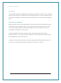
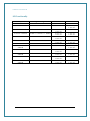
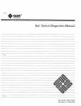
LED Functionality
Description
IP STACK IDLE
IP STACK ONLINE
Signal Strength
SIGNAL >= -84dBm
SIGNAL >= -84dBm
Power LED
ON
ON
IP STACK IDLE
-95dBm <= SIGNAL <= -85dBm
IP STACK ONLINE
-95dBm <= SIGNAL <= -85dBm
IP STACK IDLE
SIGNAL <= -96dBm
IP STACK ONLINE
SIGNAL <= -96dBm
SERIAL MODE IDLE
SERIAL MODE
ONLINE
SERIAL MODE IDLE
SIGNAL => -84dBm
SIGNAL => -84dBm
3 sec on
1 sec off
3 sec on
1 sec off
1 sec on
1 sec off
1 sec on
1 sec off
ON
ON
-95dBm <= SIGNAL <= -85dBm
SERIAL MODE
ONLINE
SERIAL MODE IDLE
-95dBm <= SIGNAL <= -85dBm
SERIAL MODE
ONLINE
SIGNAL <= -96dBm
SIGNAL <= -96dBm
- 61 -
3 sec on
1 sec off
3 sec on
1 sec off
1 sec on
1 sec off
1 sec on
1 sec off
Data LED
OFF
1 sec on
1 sec off
OFF
1 sec on
1 sec off
OFF
1 sec on
1 sec off
OFF
1 sec on
1 sec off
OFF
1 sec on
1 sec off
OFF
1 sec on
1 sec off
Intelimax User Manual
Modem Debugging
Local Connection Checking
In order to verify that the modem is operating correctly locally follow the below steps:
1. Check that modem Power LED is either solid on or mostly on. The better the
signal strength the more time the Power LED will stay on.
2. In serial modem mode:
a. Connect to modem with GUI via USB interface and check the
registration and signal strength of the modem. The status page will show
whether the modem is currently registered as well as showing the signal
level in dBm, which should be better than -93dBm.
b. Trigger a connection through the modem (either CSD or PPP
connection) and ensure that the data light will correctly flash to indicate
data transfer through modem.
3. In IP Stack auto mode:
a. Connect to modem with GUI via USB interface and check the
registration and signal strength of the modem. The status page will show
whether the modem is currently registered as well as showing the signal
level in dBm, good levels are better than -81 dBm.
b. Ensure that the modem has a data connection which should be
automatically set up by the IP auto modem connection function. If the
data LED is flashing then this connection has been established.
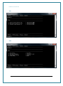
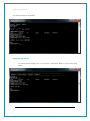
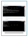
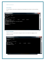
Remote Connection Checking
In order to verify that the modem is correctly operating when the modem is remotely
located please follow the below steps:
1. In serial modem mode with CSD connection, dial into the modem data number:
a. If the response is ‘BUSY’ then the SIM card is not correctly provisioned.
b. If the response is ‘NO CARRIER’ immediately then the SIM card is off line
and not registered.
c. If the response is ‘NO CARRIER’ after some time, then the modem auto
answer is not working correctly but the SIM card is registered.
d. If you are able to connect to the modem (response is ‘CONNECT’, then
you can remotely check the settings on the modem by changing to an
IP mode and making a connection to the modem using the
- 62 -
Intelimax User Manual
configuration GUI.
2. In IP Stack modes:
a. Open the GUI with an IP connection to the modem and log in.
i. Check that the settings are correct for the equipment that you
are wanting to connect to, including the serial baud rate etc.
ii. Check that the signal strength is of a good level, better than -81
dBm.
b. Use an SNMP viewer to connect to the modem SNMP server.
i. Check signal strength, good levels are better than -81 dBm.
ii. Check that the modem settings are correct.
3. In either mode send an SMS to the modem to perform the following:
a. Check RSSI: By sending INTELIMAX.PARK.RSSI to the modem the modem
will respond with the RSSI which should be better than -81 dBm.
b. Check APN and WAN connection using: INTELIMAX.PARK.WANIP. The
response
is:
“IP:<IP.IP.IP.IP>,APN:<APN>,ID:<ID>,PW:<PW>,Auth:<PAP,
CHAP,BOTH>,Reg:<0,1>,Sig:<CSQ>”
c. If
neither
command
work
INTELIMAX.PARK.REBOOT
- 63 -
then
reboot
the
modem
using:
Intelimax User Manual
Telnet / S S H C o m m a n d s
Using Intelimax Telnet / SSH commands allows you to configure the modem remotely,
also you can send diagnostic commands here is summary off of tasks that you can
perform
1. Stat : Used to display sys log, system info and DNS settings
2. Setup: using this menu you can setup system settings, Dynamic DNS, operation
mode, SNMP and SNTP settings
3. Send Direct AT commands to the modem module
4. Check signal strength
5. Use Ping command
6. Check system up time
7. Set the modem to factory default
8. Reboot the modem
Connecting to the modem via telnet
To access the modem via Telnet or SSH you will need the following
1. A Telnet or terminal software you can use windows telnet
2. Telnet needs to be enabled on the Intelimax
3. Modem IP Address or Dynamic DNS URL
4. Modem Username and Password
Connection Steps
1. Run your telnet software and put the modem IP address or URL
2. Enter your username and password
3. Type help to display all available configuration commands
Screen Shoots showing the different telnet commands
- 64 -
Intelimax User Manual
Once you login to telnet. You can choose whether to start telnet service, set up
configuration, Configure via AT command, use ping function, show uptime reboot and
reset the modem remotely to factory default using option provided i.e stat, setup, at,
ping, uptime, reboot and defconfig respectively.
- 65 -
Intelimax User Manual
Stat
Status of INTELIMAX
Log
Shows the syslog information if it is not set as remote syslog
Sysinfo
Shows F/W version and system Time and IP Address of Intelimax
DNS
Display Primary DNS and secondary DNS address of Intelimax
- 66 -
Intelimax User Manual
SETUP
1. SYSTEM
Users can change Admin password, telnet port, Enable/Disable Remote
Syslog and can enter up to three phone number for SMS
2.DDNS
Users can configure Dynamic DNS using this command
3.MODE
Intelimax support IP stack and Serial mode only, using this option(Mode)
users can configure WAN scheduler, UART/Serial port setting and IP stack
setting
4.SNMP
Users can enable/disable this feature that allows network monitoring
5.SNTP
Users can enter server address, Activate and De-activate day light
saving and even change time zone
- 67 -
Intelimax User Manual
SYSTEM
DDNS
- 68 -
Intelimax User Manual
MODE
1.WAN
This command will allow users to select operating mode,
configure
users
name
and
password,
enter
APN,
Enable/Disable Auto PIN function, enter PIN code and
configure WAN scheduler.
2.WAN Scheduler
This command will allow users to control WAN connection in a
specified time.
Day of week[0~6],
Start hour[0~23],
Start Minutes[0~59],
Start hour[0~23],
Start Minutes[0~59],
Engine power [0, 1]
E.g.: Scheduler 1: 0,0,0,23,59,1 Sunday from 0:)0 to 23:59
scheduler with engine power off
4. UART/Serial Port
This command allows users to configure serial setting e.g. baud
rate, data bit, stop bit, parity, and flow control
5.IPSTACK
Modem will be configured to use onboard IPSTACK. This option
allows changing IPSTACK Protocol (TCP/UDP), IPSTACK Port and
configuring client and server IP address.
- 69 -
Intelimax User Manual
WAN
WAN Scheduler
- 70 -
Intelimax User Manual
UART/Serial Port
IPSTACK
- 71 -
Intelimax User Manual
SNMP
General
- 72 -
Intelimax User Manual
Trap
SNTP
- 73 -
Intelimax User Manual
AT command direct to Module
Signal Strength Check
To check signal strength use “at at+csq?” command. Refer to the screen shot
below:
- 74 -
Intelimax User Manual
PING command
System uptime check.
The command uptime shows you the connection time as shown in the screen
shot below.
- 75 -
Intelimax User Manual
Set to Factory
Use defconfig to clear all the setting which will configure the modem to factory default
state.
Reset the INTELIMAX
Intelimax can be power rebooted using the reboot command after logging into the
Intelimax remotely
- 76 -
Intelimax User Manual
Extended / Intelimax Specific AT
Command Set (IP Stack Modes)
Device Information
ATI
Manufacturer: Maxon Australia Pty Ltd
Model Number: MA-2015
Product Name: Intelimax
F/W Revision: 0.0.0 [201201130929]
H/W Version: 1.0
Module F/W Revision: 11.810.09.05.00
LAI: 50506
LAC: 4eeb
CellID: 00cb63b3
IMEI: 354283040117446
OK
AT+CGMI
Maxon Australia Pty Ltd
AT+CGMR – Firmware version
+CGMR: 2.0.8 [201409230653]
AT+CGSN – IMEI number
354283049080793
Wan extension function
AT$$WANSE?
$$WANSE:
PINGCHECK:Enable,0,0,0.0.0.0,
BACKOFF:Disable,0,0,0,0
OK
Parameters
$$WANSE: X,X,X,X,X,X
0,1 PINGCHECK,BACKOFF
- 77 -
Intelimax User Manual
0,1 Disable/Enable both expansion PINGCHECK and BACKOFF
1~60 Interval of PINGCHECK/40~59 Seconds of 1st retrial interval of BACKOFF
1~60 Fail count of PINGCHECK/2~10 Minutes of 1st retrial duration of BACKOFF
IP address of 1st server of PINGCHECK/10~59 Minutes of 2nd retrial interval of BACKOFF
IP address of 2nd server of PINGCHECK/2~10 Hours of 2nd retrial duration of BACKOFF
OK
WAN authentication
AT$$WANSA?
$$WANSA: 1,telstra.extranet,0,,,*99#,0,,0,0,0,0,00:00,0
OK
Parameters
$$WANSA: X,X,X,X,X,X,X,X,X,X,X,X,X,X,X,X
1,2 IPStack Auto/Manual
Access Point domain Name
0,1,2 NONE/PAP/CHAP
Username
Password
Dialup number
0,1 Auto PIN Disable/Enable
PIN code
0 ~ 24 Hours of Periodic reset
0,1 Disable/Enable Reset (TCP Server Listening) – Server – If enabled will wait until client
drops connection
0,1 Disable/Enable Reset (TCP Connected State) – Client – If enabled will wait until
Intelimax client drops connection to a server or server drops connection
0,1 Disable/Enable Reset (At scheduled Time)
HH:MM for Reset (At scheduled Time, 24 hour format)
Battery (12.3 volts ON, 11.9 volts OFF)
0,1~100 LCP Echo Interval
0,1~100 LCP Echo Failure
OK
- 78 -
Intelimax User Manual
Periodic reset
AT$$RESET=24
$$RESET: 24
OK
Parameters
$$RESET: X
0 ~ 24 Hours of Periodic reset
WAN scheduler
AT$$WANSS?
$$WANSS: 0,Disabled
OK
Parameters
$$WANSS:
0,1 RS232 line driver power down
0,1,2 Disable/Day of Week/Duration
0,1 Delete/Add schedule/5~59 Minutes of power up
0~28 Entry number of day of week [Delete]/0,1, 2,3,4,5,6 Day of week[Ddd]/5~59
Minutes of power cycle
0~23 Hours of start
0~59 Minutes of start
0~23 Hours of finish
0~59 Minutes of finish
0,1 Engine power down
OK
IP Stack setting
AT$$WANSI?
$$WANSI: 1,1,1,0,0.0.0.0,0.0.0.0,30000,1,300,20,0,0
OK
Parameters
$$WANSI: X,X,X,X,X,X,X,X,X,X,X,X
0, 1,2 None/Server/Client
- 79 -
Intelimax User Manual
0,1 Disable/Enable Notify Boot Message
0,1 Disable/Enable Notify IPStack Message
0,1 TCP/UDP
xxx.xxx.xxx.xxx Primary IPAddress
xxx.xxx.xxx.xxx Secondary IPAddress
0 ~ 65535 Port Number
0,1 Disable/Enable Keep Alive
1 ~ 3600 Seconds Keep Alive Interval
5 ~ 60 Seconds Network Dormant Period UDP
0,1 Disable/Enable UDP Keep Alive
0,1,2 ~ 60 Disable/Handshake/Seconds UDP Wake Up
OK
SNMP
AT$$SNMPS?
$$SNMPS:
Disable,public,private,DHAGENT,support@maxon.com.au,AUS,192.168.0.200,192.168.0.2
01,192.168.0.202
OK
Parameters
$$SNMPS: X,X,X,X,X,X,X,X,X
0,1 Disable/Enable
Read community
Write community
Name
Contact
Location
Trap 1 IP address
Trap 2 IP address
Trap 3 IP address
OK
DDNS
AT$$DDNSS?
- 80 -
Intelimax User Manual
$$DDNSS: Disable,,,
OK
Parameters
$$DDNSS: X,X,X,X
0,1 Disable/Enable
DomainName
UserName
Password
Service Provider
OK
System
AT$$SYSTS?
$$SYSTS:
admin,admin,Enable,23,Enable,Disable,192.168.0.50,Disable,+61427933242,+6142793324
2,+61427933242
OK
Parameters
$$SYSTS: X,X,X,X,X,X,X,X,X,X,X
UserName
Password
0,1 Telnet Disable/Enable
Telnet Port Number
0,1 Syslog Disable/Enable
0,1 Remote syslog Disable/Enable
Remote syslog server address
0,1 SSH Disable/Enable
Phone number of Administrator
Phone number of Administrator
Phone number of Administrator
OK
- 81 -
Intelimax User Manual
maXconnect
To enable maXconnect on the Intelimax either use the GUI or enter the following
commands when the modem is in IP Stack Auto mode.
$$MAXCNT: 0,120,portal.maxconnect.com.au,1883,updates.maxconnect.com.au
OK
AT$$MAXCNT=?
$$MAXCNT: X,X,X,X,X
0,1 Disable/Enable
Refresh Interval
Broker URL
Broker Port
FTP update server URL
OK
Serial (UART) port
AT$$SPORT?
$$SPORT: 115200,8,N,1,None
OK
Parameters
$$SPORT: X,X,X,X,X
2400,4800,9600,19200,38400,57600,115200 Baud rate
7,8 Data bits
N,E,O None/Even/Odd
1,2 Stop bits
None, Software, Hardware Flow control
OK
Engine Band
AT$$BAND?
$$BAND: 40000000
OK
- 82 -
Intelimax User Manual
Parameters
$$BAND:
1: GSM 850
2: GSM DCS SYSTEMS
4: GSM EGSM 900
8: GSM PGSM 900
10: GSM RGSM 900
20: GSM PCS
40: WCDMA I IMT2000
80: WCDMA II PCS1900
400: WCDMA V 850
1000: WCDMA VIII 900
40000000: AUTO
OK
Examples:
/ GSM 850/900/1800/1900
AT$$BAND=3f
$$BAND: 0000003f
OK
The AT commands on the module can be set and checked directly using AT$$DIRAT.
AT$$DIRAT="at^syscfg=2,2,380380,1,2" – make sure module band is set
OK
AT&W
OK
AT$$RESET
OK
// WCDMA 850
AT$$BAND=400
OK
AT$$DIRAT="AT^SYSCFG=2,2,4000000,1,2"
- 83 -
Intelimax User Manual
OK
AT&W
OK
AT$$RESET
OK
Check IP address of the WAN side
AT$$WAN
$$WAN: 123.209.0.204
OK
FTP
To use FTP on the Intelimax allow for append on the FTP server.
Also restrict the welcome message to less than 10 characters.
Please save and apply settings before using.
AT$$FTPCS?
AT$$FTPCS: 1,192.168.10.1:21,maxon,maxon,0,INTELIMAX,1000,1
OK
Parameters
$$FTPCS: X,X,X,X,X,X,X,X
0 - Disable
1 - Manual
2 - Hourly (0 - 24)
3 - Time of day (0 - 24)
4 - Day of month (1 - 31 days)
5 – Minutes (0 - 60)
Host IP/Domain address with Port
User name
- 84 -
Intelimax User Manual
Password
Time interval
Header of file name (limit 10 bytes/characters)
Size of file (Bytes) – maximum 102,400 bytes, maximum internal buffer size 10MB
A new file will be created each time the file size is exceeded.
Time stamp – enable (1) or disable (0) timestamp prefix (in seconds)
A reboot is required when enabling, disabling or making changes to the FTP options.
Examples:
AT command to upload every 1 hour.
AT$$FTPCS=2,20.19.62.23:21,maxon,maxon,1,FILEHEADER,10000,0
AT command to upload every 30 minutes.
AT$$FTPCS=5, 20.19.62.23:21,maxon,maxon,30,FILEHEADER,10000,0
AT command to upload every day at 8PM.
AT$$FTPCS=3, 20.19.62.23:21,maxon,maxon,20,FILEHEADER,10000,0
AT command to upload every 15th day of the month.
AT$$FTPCS=4, 20.19.62.23:21,maxon,maxon,15,FILEHEADER,10000,0
1. In the example above file size is 10000 bytes.
2. The modem would create a text file using name specified above (in the
example I have used “fileheader” as the filename)
3. The last setting 0 or 1 decides if the data is time stamped. 0 will only log data in
the text file. 1 will stamp all data logged with date and time.
The "size of file" parameter is used for limiting the file size of the csv file. All the input from
serial port will be saved in the .csv file, and once the file size of that csv file exceed the
size limit, another file will be created to hold the input. The value allowed is 1000 100*1000 Bytes.
- 85 -
Intelimax User Manual
Based on the configuration, the file could be uploaded to server periodically. For
example,
AT$$FTPCS=5,192.168.10.50:21, maxon, maxon, 30,FILEHEADER,10000,0
with this setting, the modem will send out .csv file to FTP server every 30 minutes. If the
input has not exceeded limit 10K bytes (in this case), modem will send this file only, then
generate another file for holding future input. If the input is more than 10K bytes, there
should be more than one file generated, each file should not exceed 10K bytes, all
these files will be sent to FTP server when time comes.
File uploaded with date time stamp disabled.
AT$$FTPCS=2,20.19.62.23:21,maxon,maxon,1,FILEHEADER,10000,0
AT+CSQ
AT+CSQ
AT+CSQ
AT+CSQ
AT+CSQ
AT+CSQ
File uploaded with date time stamp enabled.
AT$$FTPCS=2,20.19.62.23:21,maxon,maxon,1,FILEHEADER,10000,1
09/11/2012 15:44:05 AT+CSQ
09/11/2012 15:44:06 AT+CSQ
09/11/2012 15:44:07 AT+CSQ
09/11/2012 15:44:08 AT+CSQ
09/11/2012 15:44:09 AT+CSQ
09/11/2012 15:44:10 AT+CSQ
09/11/2012 15:44:11 AT+CSQ
09/11/2012 15:44:12 AT+CSQ
09/11/2012 15:44:13 AT+CSQ
09/11/2012 15:44:14 AT+CSQ
09/11/2012 15:44:15 AT+CSQ
AT$$FTPFL
- 86 -
Intelimax User Manual
Displays the files waiting to be uploaded
AT$$FTPSC
OK
Will start the FTP connection and upload the files. Can be used to force an upload
when in periodic mode. If no WAN connection is currently established (such as in IP
Stack Manual mode) the Intelimax will establish the PPP and socket connections,
upload the FTP files then drop the socket and PPP connections.
Signal Strength
AT+CSQ?
+CSQ: 17,99
OK
Open PPP connection
AT$$IPCTOP
Close PPP connection
AT$$IPCTCP
Open TCP/UDP Socket
AT$$IPCTOS
Close TCP/UDP Socket
AT$$IPCTCS
Change Remote Server IP address
AT$$IPCTRIP=0,ip,ad,dr,ess,<port>
Eg. AT$$IPCTRIP=0,123,456,789,01,30000
Change client/server mode
AT$$IPCFL=4,<0,1> where 0 for server, 1 for client
- 87 -
Intelimax User Manual
Eg. AT$$IPCFL=4,0 sets modem to server mode
IPStack Connection Settings
AT$$IPSCFG?
$$IPSCFG: 30,100,300
OK
AT$$IPSCFG=?
$$IPSCFG: X,X,X
IPSTACK SEND DELAY: 1 ~ 2000 msec
IPSTACK BUFFER SIZE: 32 ~ 1450 bytes
IPSTACK SOCKET TIMEOUT: <0,10~3600> sec
PPP DISCONNECT TIMEOUT: <0,30~3600> sec
OK
AT$$IPSCFG=30,100,200,301
OK
AT$$IPSCFG?
$$IPSCFG: 30,100,200,301
OK
Change modem mode
AT$$CHGMODE=
1 – IP Stack Auto
2 – IP Stack Manual
3 – Serial Modem
at$$chgmode=1
OK
Save and Reboot
AT$$RESET
At$$reset
OK
Factory Reset
AT$$FACTORY
OK
- 88 -
Intelimax User Manual
AT over IP on IPStack
AT$$OVERIP=?
$$OVERIP: X,X
0,1 Disable/Enable
Listen Port Number
OK
at$$overip?
$$OVERIP: 1,12521
OK
at$$overip=0
Require Save and System Reboot
OK
at$$overip?
$$OVERIP: 0,12521
OK
at$$overip=1,12522
Require Save and System Reboot
OK
at$$overip?
$$OVERIP: 1,12522
OK
- 89 -
Intelimax User Manual
Modem Emulation
The Intelimax modem emulation can be configured using the following AT commands:
To enable modem emulation and add a data number to IP address and port number
emulation to the list
at$$emul=1,phone_number,IP_address,port_number
e.g. at$$emul=1,01044204414,10.0.0.1,5000
To check current emulation list (must have already enabled emulation)
at$$emul?
$$EMUL: 1,3
0,01044204412,192.168.101.2,3000
1,01044204411,192.168.101.2,30001
2,01044204414,10.0.0.1,5000
OK
To Enable/Disable Modem Emulation – this must be enabled on the server Intelimax for
CONNECT message
at$$emul=0,0 – disable
at$$emul=0,1 - enable
To delete a rule from the list
at$$emul=2,list_number
e.g. at$$emul=2,1
OK
at$$emul?
$$EMUL: 1,2
0,01044204412,192.168.101.2,3000
1,01044204414,211.232.22.1,500001
OK
- 90 -
Intelimax User Manual
Modmax Compatibility Mode
This changes the IP Stack responses from Intelimax style responses to Modmax style
responses.
AT$$SPC?
$$SPC: <mode>
OK
<mode>:
0: Intelimax mode
1: Modmax mode (Default)
Write:
AT$$SPC=<passcode>
$$SPC: <mode>
OK
<passcode>:
857653: mode 0
356758: mode 1
Intelimax Mode
$$TCP_Connect_To:
125.181.12.34
[01/24/2014 08:00:36]
[01/24/2014
08:05:36]
[Connection_Close_By_Timed_Out]
Modmax Mode
[18:57:55 28 JAN 2014] $$TCP_Connect_To:
192.168.10.50
[08:31:12 24 JAN 2014] TCP connection
disconnected
- 91 -
Intelimax User Manual
TCP Delay between ‘trying to connect’ socket and ‘CONNECT’ messages
Some older systems working with the Modmax cannot handle the speed between
messages, this delay allows for these legacy systems to handle this delay.
AT$$TCPDEL=?
$$TCPDEL: X
Delay between try and connect range from 200 to 1000 mili seconds.
OK
AT$$TCPDEL=200
OK
AT$$TCPDEL?
$$TCPDEL: 200
OK
Prepare modem for hard shutdown
This function is highly recommended when using the modem with an external,
controlled power supply. If the modem is going to have its power dropped regularly this
AT command allows for the processor to perform housekeeping duties to ensure that
the shutdown process does not damage the modem or internal cellular module.
AT$$RTD
OK
SMS on Boot
The Intelimax can be configured to send an SMS at boot time using the following AT
commands:
at$$pwronsms=?
$$PWRONSMS=1,0/1 enable/disable
$$PWRONSMS=2,1/2/3,Phone Number up to 3 phone numbers
$$PWRONSMS=3,Message
- 92 -
Intelimax User Manual
Extended / Module Specific AT
Command Set (Serial Modem Mode)
AT&W
Saves AT commands
AT%RESET=1 (Serial Modem mode)
Applies saved AT commands with a reboot
Parameter
E0
E1
Q0
Q1
&C0
&C1
&C2
&C3
&C4
&D0
[&D1]
&D2
S0
Description
Do not echo command set in command state or online
command state.
Echo command set in command state or online command
state.
Return result codes.
Do not return result codes.
Circuit 109 (CF) always ON.
Circuit 109 (CF) ON in accordance with the specified service.
DCD line is High during a circuit switched call.
Circuit 109 (CF) ON. DCD is always high. This line toggles low
for 1 second when the circuit switched call is disconnected.
Circuit 109 (CF) ON. DCD is Low. High when modem has
successfully established a PPP Data (packet switched) call
(only applies to IP STACK)
Circuit 109 (CF) ON. DCD is Low. High when modem has
successfully established a PPP Data and opened a socket with
remote server(packet switched) call (only applies to IP STACK)
Ignore circuit 108/2 (CD).
Enter online command state following ON-to-OFF transition of
circuit 108/2. See service specific AT command processing for
service state transitions.
Enter command state following On to Off transition of circuit
108/2. See service specific AT command processing for service
state processing requirements.
Automatic
answering.
[Enable
automatic
[1 to 255]
answering after (Value: 1) x 6 seconds.]
0
0: Not Answer
- 93 -
Intelimax User Manual
Command
Command
TE2
TE2
MT2
MT2
Notify
TE2
MT2
Value
phone_number:
for Packet Switched Data: *99# (Australia – requires authentication)
for Circuit Switched Data: You will need a data number ( Code 2620 activated
on the SIM account)
Notify
Command
TE2
TE2
MT2
MT2
Notify
TE2
MT2
Command
TE2
MT2
Notify
TE2
MT2
ATD<phone_number>
CONNECT (Data call connected)
Connect <Speed> if connect_baud is set.
NO CARRIER (Data call failure)
AT: RING
ATA (answer data call)
CONNECT (Data call connected)
CONNECT <SPEED> if connect_baud is enabled.
NO CARRIER (Data call failure)
Call State
+++ (escape command to go to off-line command state)
ATH (release call)
NO CARRIER
Periodic Reset
at$$preset=2
OK
at$$preset?
$$PRESET: 2
Getting S0 value in serial modem mode
Please use ATS0?
Command to get the SO value. AT&V command will give you
incorrect SO Value:
ATS0=2
OK
ATS0?
2
OK
Single AT command SMS AT+MMC SMSMO
AT+MMC SMSMO <Phone number> <message><CR>
Eg. AT+MMC SMSMO 0400123456 Boiler Temperature Too High!<CR>
Maximum length of message is 160 characters.
Some characters are not supported: \, [, ], ^, ~, `
- 94 -
Intelimax User Manual
Prepare modem for hard shutdown
This function is highly recommended when using the modem with an external,
controlled power supply. If the modem is going to have its power dropped regularly this
AT command allows for the processor to perform housekeeping duties to ensure that
the shutdown process does not damage the modem or internal cellular module.
AT$$RTD
OK
SMS on Boot
The Intelimax can be configured to send an SMS at boot time using the following AT
commands:
at$$pwronsms=?
$$PWRONSMS=1,0/1 enable/disable
$$PWRONSMS=2,1/2/3,Phone Number up to 3 phone numbers
$$PWRONSMS=3,Message
- 95 -