1
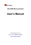
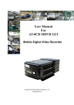
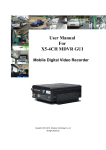
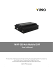
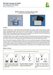
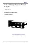
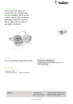
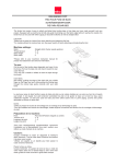
ZDJ Series
ZDJ-510 Microcontroller
User’s Manual
© Sunrise Electric Co.,Ltd
Phone:0571-88186075
Copyright Notice
This document is copyrighted 2002 by Sunrise Electric Co.,Ltd. All rights are reserved.
Sunrise Electric Co.,Ltd reserves the right to make improvements to the products
described in this manual at any time without notice.
No part of this manual may be reproduced, copied, translated or transmitted in any form
or by any means without the prior written permission of Sunrise Electric. Information
provided in this manual is intended to be accurate and reliable. However, Sunrise Electric
assumes no responsibility for its use, nor for any infringements upon the rights of third
parties which may result from its use.
Printed in P.R.China May 2002
2
Index:
1. Introduction
2. How to use
3. Notice
4. FAQ
5. Appendix A: Function Code & Error Code Description
6. Appendix B: Electric Connection Specification
3
§Introduction
This document contains Sunrise Electric Co.,Ltd’s ZDJ series
microcontroller’s using guide and notice. Operator should use the machine
only after thoroughly reading of this manual. If you have any problem during
operation, please refer to Notice and FAQ section first.
§How to use
figure 1.
Controller Panel
Figure 1 shows Controller panel, which contains three function blocks:
keyboard, display, and trademark. All parameters can be easily modified
through keyboard.
1. How to use keyboard
The keyboard has 14 buttons in all. Following describes each
button’s function.
¾ SET: Press ‘SET’ to enter setup mode, each function is
identified by its unique function code, press ‘SET’ once to enter
function 01 - modify bag making length and drag motor speed.
Function 01 has difference from other function code, the code 01
is not displayed at LED. Each time press ‘SET’ button, funtion
code is increased by 1 ,then can modify other parameters.
¾ ←: when enter setup mode, ‘←’is used to left shift shining bit
¾ →: when enter setup mode, ‘→’is used to right shift shining bit
¾ ↑: when enter setup mode, ‘↑’is used to increase shining bit
by 1
¾ ↓: when enter setup mode, ‘↓’is used to decrease shining bit
4
by 1
CLEAR All: is used to clear totally bag group to zero
CLR: is used to clear current bag group to zero
CW: is used to jog step motor forward
CCW: is used to jog step motor backward
F/S: is used to alter between two operate mode: fast detect and
slow detect, disabled when making blank bag. Fast detect mode
is mainly used for normal bag making, slow detect is for test
purpose mainly
¾ P/B: is used to choose making blank bag or printed bag
¾ B/W: is used to choose optic detector’s operation mode, the
LED inside button indicates if the color mark is detected by optic
detector, if yes it is light, or it is dark
¾ RUN: is used to start running. The LED inside indicates if it is on
running mode
¾ STOP: is used to stop running. The LED inside indicates if it is
normal stop(GREEN LIGHT) or error stop(RED LIGHT)。
2. How to understand LED display
LED display area is combined with 4 section , they are bag length,
motor speed, speed, total number. User can setup Bag length and
motor speed manually, speed and total number is read only and just
for presenting information. Below is their detailed description:
¾ Bag Length: consists of 4 8-SEG LED, bag making length can
dynamic set from 1mm – 9999mm at 1mm increment. When
make blank bag, real bag length = set bag length, when make
printed bag, real bag length = set bag length + optic detect length
¾ Motor speed: presented by 1 8-SEG LED, it sets drag
motor(step motor) working speed, 0 is slowest, 9 is fastest, can
be set dynamic during working
¾ Speed: consists of 3 8-SEG LED, when in working it shows
current bag making speed in ppm
¾ Total number: consists of 6 8-SEG LED, shows total bags that
have made
Otherwise, the function code and error code are all displayed in LED
display area. The function code is shown as F ? ?, and the error code is
shown as E ? ?. Here, “?” is the corresponding number. Function F 02 is
Bag Group Set, F 03 is Bag Pause Number Set , F 04 is Roller Diameter
Set. The error code E 02 is Keyboard Error, E 01 is Preset data lost. All
details of the function code and error code are shown in Appendix A.
3. How to set parameters
Accurate parameters make better bag-making. For the first time of
using, parameters as follows must be set: bag length, motor speed,
bag group, number of pause, diameter of rollers.
¾ Bag length: the set length of bags, appreciably less than real
¾
¾
¾
¾
¾
5
length. When stopping and bag-making, length can be modified if
the button ‘SET’ is pressed one time. Sparkling digit can be
modified. ‘←’ and ‘→’ are used to circularly choose digit for
modification. Max 9999 mm, Min 1 mm.
¾ Motor speed: the speed of step motor, 9 the fastest, 0 the
slowest. When stopping and bag-making, speed can be modified
if the button ‘SET’ is pressed one time.
¾ Bag group: the number of bags for one group. The buzzer will
sound when the number reaches. Only when stopping can bag
group be modified. Press button ‘SET’ until ‘F02’ appears. Refer
to Figure 2 in Appendix 1. ‘←’ and ‘→’ are used to circularly
choose digit for modification. ‘↑’ and ‘↓’ are used to
change the value. Max 9999, Min 6.
¾ Number of pause: the pausing number after bag group reaches.
Only when stopping can number of pause be modified. Press
button ‘SET’ until ‘F03’ appears. Refer to Figure 3 in Appendix 1.
‘ ← ’ and ‘ → ’ are used to circularly choose digit for
modification. ‘↑’ and ‘↓’ are used to change the value. Max
99, Min 0 ( i.e., No pausing).
¾ Roller’s Diameter: the diameter of roller, Unit mm. Only when
stopping can roller diameter be modified. Press button ‘SET’ until
‘F05’ appears. Refer to Figure 4 in Appendix 1. ‘←’ and ‘→’
are used to circularly choose digit for modification. ‘↑’ and
‘↓’ are used to change the value. Max 130 mm, Min 30 mm.
Black/White, Fast/Slow, and Print/Blank have been demonstrated in
the ‘How to use keyboard’.
§Notice
I. DO NOT LEAVE THIS CONTROLLER IN AN UNCONTROLLED
ENVIRONMENT WHERE THE STORAGE TEMPERATURE IS
BELOW –20 CELSES OR ABOVE 60 CELSUS. IT MAY DAMAGE
THE CONTROLLER. ALSO DO NOT USE CONTROLLER AT
FERROMANEGTIC CIRCUMSTANCE.
II.
DO NOT OPEN THE CONTROLLER BOX.
III. WHEN ERROR OCCURS, RECORD ERROR CODE FIRST,
THEN REPORT IT TO TECHNICIAN FOR REPAIR. ALSO READ
FAQ FIRST.
6
§FAQ
1) Why some buttons have no answer when pressed,i.e.,the buzzer don’t sound?
These buttons is automatically disabled, because its function has conflict with current
task.
2) Why the machine stops abnormally sometimes?
To minimize the waster , the controller will automatically stop the machine and
generate an alarm when the number of wasters exceeds 5. which may caused by over
speed or optic detect error, please check the motor speed or adjust the optic detector.
3) How to resolve the error E 02?
E 02 is error code for keyboard, please refer to Figure 6 in Appendix A, and contact
technician for more help.
4) Why when start displays error code E 01, and how to resolve?
Error code of E 01 denotes that the preset data lost, which is shown in Appendix A
Figure 5. Please setup all parameters again and then can go on work. If error code of
E 01 still shown on next restart, please change the battery in the control driver. The
battery in controller is lithium battery, which can be used over 10 years under normal
condition.
5) Why the display is black after start?
Please check the power switch and the DC input power connection.
7
§Appendix A: Function Code and Error Code Description
Function
Code
F 02
F 03
F 04
Error
Code
E 01
E 02
Detail
Bag Group Set
Bag Pause Number Set
Roller Diameter Set
Preset Data Lost
Keyboard Error
Table 1. Explain of Function Code and Error Code
Figure 2. F 02 Bag Group Set
Figure 3. F 03 Bag Pause Number Set
8
Figure 4. F 04 Roller Diameter Set
Figure 5. E 01 Preset Data Lost
9
Figure 6
E 02
Keyboard Error
10
§Appendix B:Electric Connection Description
No.
Name
1
2
3
4
5
6
7
8
9
10
11
12
13
14
15
16
17
18
19
20
21
22
23
24
25
26
+5V
GND
+12V
COM
BUT
RUN
STOP
CW
GND
CP
CW/CCW
+12V
COM
OPAA
OPCC
+12V
COM
B/W
COM
SPK
+12V
EP
+12V
OUT1
BK1
BK2
Detail
+5V DC Input
+5V DC Ground
+12V DC Input
+12V DC Ground
Common Pin of Outside Parallel Buttons
Outside Parallel Button—Run
Outside Parallel Button—Stop
Outside Parallel Button—CW
Connected to Common Port of Step Motor Driver COM
Connected to Impulse Input of Step Motor Driver CP
Connected to Change Directional Input of Step Motor CW/CCW
Connected to Board of Blade Position Power +
Connected to Board of Blade Position Power Connected to Port A of Board of Blade Position OPAA
Connected to Port A of Board of Blade Position OPCC
Connected to Optic Detector Power +
Connected to Optic Detector Power Connected to Optic Detector Black/White Output
Connected to Speaker Input I
Connected to Speaker Input II
Connected to Board of Stiletto Input I
Connected to Board of Stiletto Input II
Connected to Controller of Outside 12V Relay I
Connected to Controller of Outside 12V Relay II
Connected to Outside Start Controller Input of Transducer I
Connected to Outside Start Controller Input of Transducer II
11