1
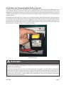
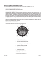
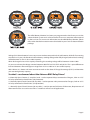
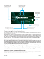
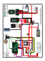
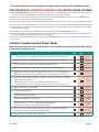
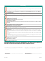
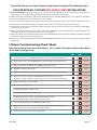
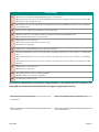
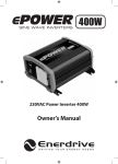
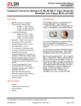
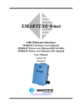
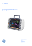
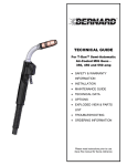
Lithium Power Pack Lithium-Ion Battery System Owner’s Manual V2.0-2015 Lithium Power Pack Lithium-Ion Battery System After 2 years of research, testing and proving, and a further 2 years of infield sales, Enerdrive has designed and created a COMPLETE Lithium Battery & Installation System so your Li-Ion battery bank is fully protected. Most importantly, our system is designed to give the maximum performance, longevity and SAFTEY in your valuable installations. Be aware that the market is abuzz with the hot topic of Lithium Ion Batteries; and we can tell you from our testing to date that all the hype of their performance and capabilities is TRUE. However what we can also inform you is that all the stories of their ‘Issues’ are unfortunately also true. However the so called “issues’ of lithium can be avoided with some very basic rules about protection. • Never go over voltage whilst charging them • Never let them go ‘Dead’ Flat • Keep the individual cells ‘Balanced’ What this lesson taught us was that to do Lithium – IT HAD TO BE DONE RIGHT!! So we developed our own Lithium Power Pack for the Australian market with the emphasis on ‘built like a tank’; and even to the extent of being a little bit ‘overkill’ on the packaging and protection. So how does our system actually work? The Advance BMS relay driver is designed to take a loop signal wire from the ePRO battery meter for low state of charge (SOC%)/Voltage & Hi system voltage and a loop signal wire from the batteries Cell balancers Hi/Low Volt cut-out circuit. System Program Selection Switch; The Advanced BMS Relay Driver has 2 pre- programed settings. Output 1-4 Enabled - is programmed to utilise the output contacts. Using this program allows you to have the charging sources run through external relays allowing the BMS to isolate the charging source in the event of a cell voltage being too high without turning the whole electrical system off. In the event of low SOC% the main battery relay will be disengaged to protect the battery. • We strongly recommend this option for all installations. Output 1-4 Disabled - is programmed to bypass the output contacts. If the battery SOC% is low or cell voltage is high, the main battery relay will be disengaged, turning off the whole electrical system to protect the battery. • Subject to specific requirements, this option may only be suitable for certain applications. If unsure, please contact Enerdrive for further details. V2.0-2015 Page 2 So how does the “Advance Enabled Setting” operate? If a battery cell goes “Hi Voltage” and “opens” the hi voltage loop wire, then the Advanced BMS Relay Driver will activate the output contacts that will drive the installed relay/contacts to cut out all charging sources (solar/ vehicle/main charger) for 10 minutes. If the cell has not come back within range before 10 minutes, it will stay active for another 10 minutes and repeat until the cell/s are within range. This setup allows the system loads to still be powered. If the ePRO Battery monitor sees a LOW SOC% or overall low voltage, then the main battery relay will trip out. You will need to start a charging source and re-engage the main battery relay by pressing in the Yellow button on top of the main battery relay. The Advanced BMS Relay Driver will turn the main battery relay OFF every 6min if the SOC% on the battery monitor is still below the set point. So this may need to be reset a few times before the SOC% set point reaches it re-engagement point. Main Battery Relay PLEASE NOTE The battery has a self-discharge rate of 5% per month @ 25°C. When storing the battery with the main latching relay disengaged, the ePRO Battery Monitor and Advance Relay Driver will still be powered, adding a further drain on the battery. It is the responsibility of the end user to maintain the battery in a charged state. The battery should not be left for more than 30 days without checking its charge state. Enerdrive recommend that a battery left in a “storage state” should be checked and charged as often as possible (maximum 30 days) to maintain maximum life expectancy of the battery. Failure to follow these requirements will see an early failure of the battery which is not covered under warranty. V2.0-2015 Page 3 What’s in the Enerdrive Lithium System? To use the Enerdrive Lithium Power Pack you need to use two items together. These are: • The actual lithium power pack battery box. • The Advance BMS controller board which includes • The Advance BMS Relay Driver box • The ePRO Battery Monitor for accurate monitoring and control of the battery pack’s state of charge. This monitor also logs historical data on the batteries usage and provides the trigger switch for a low SOC% or Low Overall voltage. The monitor is pre-programmed with all of the alarm set points to match the specific installation. The meter will show all of the relative information like Volts, Amps, Amp-hours, Percentage State of Charge & Time to go. It will also record all of the history data of the Lithium battery, Deepest Discharge, Battery Cycles, Hi/Low Voltage & Amps, All Alarm History Etc. This is a critical part of the Lithium battery installation kit. • A Blue Sea 500amp main battery latching relay which is activated by the ePRO Battery Monitor when the low state of charge (percentage is reached). • A Class T Fuse for system protection. • 95mm² Battery cable from the battery to the Connection Kit. 4 5 3 6 2 7 8 1 9 12 11 10 1. Charge battery indicator 2. Numeric value indicator field 3. Setup lock / Master lock indicator 4. Main battery or Auxiliary battery indicator 5. State-of-charge bar 6. Charging in progress indicator 7. Alarm activated indicator 8. Readout units 9. Synchronize indicator 10. Next value or Right key (>) 11. Menu key 12.Previous value or Left key (<) V2.0-2015 Page 4 The ePRO Battery Monitor has been pre-programmed at the factory to suit the selected Lithium system and is software locked. There is no setup interaction required by the end user. For more user information on the ePRO Battery Monitor, please refer to the detailed instruction manual included in your Caravan documentation package. Voltages for Lithium batteries have a very narrow window compared to lead acid batteries. With all of our testing over the last 2-3 years, the Enerdrive Lithium battery standing voltage when fully charged (with no loads running) will be between 13.35v-13.45v at 100% capacity. When discharged to near 25% capacity remaining, the standing voltage will be between 12.90v-13.00v As you can see here, the voltage variance between 100% full and 25% full is only 0.55v. This is quite different to lead acid batteries where voltage can range from 12.72v at 100% to 11.88v at 20% capacity. With Lithium, it is better and more accurate to work on the State of Charge Percentage (SOC%) to determine your remaining battery capacity. So what’s so advanced about the Advance BMS Relay Driver? 2 x Normally Open Contacts (1 amp Max) each - used to operate Relays connected to Chargers, Solar or a DC/ AC relay connected to Combi Units (HV protection) 1 x Normally Open/Closed Contact (10 amp Max) - used to operate a relay connected to Chargers, Solar or a DC/ AC relay connected to Combi Units. (HV protection) 1 x Normally Open/Closed Contact (10 amp Max) - used to operate Field wire of Alternator, Requirements of Alternator must be assessed to see if this is suitable as will not suit all applications V2.0-2015 Page 5 When Red Light is ON Contact is closed due to hi cell voltage When Red Light is ON Contact is open due to hi cell voltage Output 2 NO/CM/NC Output 3 NO/CM/NC Output 4 Max -10amp Max -10amp System Program Selection Switch Combi Program Dip Switch Standard Program N-O Max -1amp Output 1 Advanced BMS Relay Driver N-O Max -1amp Input 2 Input 1 Batt BMS ePRO When Green Light is ON unit has power DC Power 9-60V Input Connection to Blue Sea System Part #7700-12V / #7702-24V RED/ORG/BRN/YEL/BLK Rev:2.0 When Green Light is ON Blue Sea Relay is engaged When Green Light is ON Cell voltage is within range When Green Light is ON SOC% is within range Troubleshooting the Lithium Battery System Q: If the battery monitor reads 24% or less or the battery voltage has reached 12.4v or less, and the power has gone out in the van? A: The battery has reached its maximum discharge and the main battery relay has dis-engaged to protect the battery. Turn off all loads and turn on the charging sources. Once the percentage on the ePRO Meter reaches 28%, you can push the yellow button on the main battery relay to re-engage the main battery switch and start turning on your loads. Keep charging sources connected until the battery reaches maximum charge 100% Q: What if I see red lights on, on the “outputs” of the Advance Relay Driver Box A: If a battery cell goes Hi Voltage and cuts the HI Voltage loop wire then the Advanced BMS Relay Driver will activate the output contacts (turning red) and will drive the installed relay/contacts to cut out all charging sources (solar/vehicle/main charger) for 10min. If the cell has not come back within range before 10min, it will stay active for another 10min and repeat until the cell/s are within range. Q: What if the main battery switch has tripped out, but all the lights on the Advanced BMS Relay Driver box are green and the battery monitor is 26% or higher in capacity? A: This has happened because the ePRO monitor has registered a “hi voltage” (15.2v or higher) and has tripped out the main battery switch. Push the yellow button on the main battery relay to re-engage the main battery switch. If the battery switch continues to disengage, contact the manufacture for assistance. Q: What if I see “no lights” on the Advance Relay Driver Box A: If this happens, please check the in line 1amp fuse connected to the “DC Power” input on the Advance Relay Driver Box. If this fuse is intact, contact the manufacture for assistance. V2.0-2015 Page 6 Lithium Battery Warranty: Two Year Limited Warranty Our goods come with guarantees that cannot be excluded under the Australian Consumer Law. You are entitled to a replacement or refund for a major failure and for compensation for any other reasonably foreseeable loss or damage. You are also entitled to have the goods repaired or replaced if the goods fail to be of acceptable quality and the failure does not amount to a major failure. The limited warranty program is the only one that applies to this unit, and it sets forth all the responsibilities of Enerdrive. There is no other warranty, other than those described herein. Any implied warranty of merchantability of fitness for a particular purpose on this unit is limited in duration to the duration of this warranty. Enerdrive Pty Ltd warrants its Lithium batteries (hereafter referred to as “Battery”) to be free of defects in material and workmanship for the following Applicable Warranty Period: • 2 years for commercial, industrial, marine and automotive applications in cycling and non-cycling applications. The battery is warranted, to the original purchaser only, to be free of defects in materials and workmanship for two years from the date of purchase without additional charge. The warranty does not extend to subsequent purchasers or users other than OEM applications. • An additional 24 months Pro-Rata warranty is included in the battery. The pro-rated price is calculated as a percentage of the current suggested retail price. Pro-Rata warranty applicable to original end user only. Enerdrive does not warrant the battery for use in any residential system sold with the intent or purpose of a “Tariff Adjustment Program” of any type. The Enerdrive ePRO battery monitor that is standard with every Lithium-Ion battery kit is pre-programmed by Enerdrive to suit the battery configuration. Any changes that are made to the pre-configuration programming of the ePRO meter will void all warranty of the battery & system. The warranty does not cover a battery reaching its normal end of life which may occur prior to the warranty period stated above. Depending on the application a battery can reach its normal end of life before the end of the warranty period. A battery can deliver only a fixed number of usable cycles / amp-hours over its lifetime and is considered to have reached its normal end of life if the application uses up all of these cycles / amp-hours, regardless of the time the battery has been in service. Therefore Enerdrive reserves the right to deny a warranty claim if it determines the battery to be at its normal end of life, even if the claim is lodged within the applicable warranty period. The Applicable Warranty Period begins from the date of purchase with original receipt, or, if no receipt is available, from Enerdrives invoice / shipping date. Batteries determined to meet the conditions of this warranty will be replaced free of charge if, at the sole discretion of Enerdrive, adjustment is necessary due to defect in material or workmanship. Batteries for warranty replacement consideration are to be returned to the original supplying distributor/dealer. Batteries replaced under the warranty provisions will be shipped with a replacement warranty sticker and carry only the remainder of the original Applicable Warranty Period. The battery is not designed or warranted in the following areas: • The Battery is NOT to be used in any Aviation aircraft application. • The Battery is NOT to be used in any lifesaving applications • The Battery is NOT to be exported to USA/Canada and their territories • Any residential system sold with the intent or purpose of a “Tariff Adjustment Program” of any type. V2.0-2015 Page 10 PLEASE NOTE The battery has a self-discharge rate of 5% per month @ 25°C. When storing the battery with the main latching relay disengaged, the ePRO Battery Monitor and Advance Relay Driver will still be powered adding a further drain on the battery. It is the responsibility of the end user to maintain the battery in a charged state. The battery should not be left for more than 30 days without checking its charge state. Enerdrive recommend that a battery left in a “storage state” should be checked and charged every 30 days to maintain maximum life expectancy of the battery. Failure to follow these requirements will see an early failure of the battery which is not covered under warranty. General Provisions: Enerdrives Pty Ltd has no obligation under the limited warranty herein in the event the battery is damaged or destroyed as a result of one or more of the following: • Wilful abuse, misuse, physical damage, neglect or if the decorative cover has been removed. • Natural forces such as wind, lightning, hail; damage due to fire, collision, explosion, vandalism, theft, penetration or opening of the battery case in any manner. • The supplied Enerdrive ePRO battery monitor is pre-programmed by Enerdrive if and any changes are made to the pre-configuration programming of the meter, all warranty is void. • The battery MUST be installed in an upright position. Installing it upside down or laid on its side will void warranty. • Overcharging, undercharging, charging or installing in reverse polarity, improper maintenance, allowing the battery to be deeply discharged via a parasitic load or mishandling of the battery such as but not limited to using the terminals for lifting or carrying the battery. • Charging sources that do not have programmable lithium profile configurations and charge voltage between 13.5V and 14.5V (no lower than 13.0V and no higher than 14.7V) will cause early failure of the battery. Use of such chargers with the battery will also void the battery’s warranty. For applications where an alternator is present, the alternator must deliver between 13.5V and 14.2V when measured at the Battery’s terminals. Alternators that do not have a regulated charge between 13.5V and 14.2V (no lower than 13.0V and no higher than 14.7V) will cause early failure of the battery. Use of such alternators with the battery will also void the batteries warranty. • All Enerdrive batteries are supplied with an additional battery installation kit. Failure to install or properly install the battery and its installation kit will void the warranty • Repair or attempted repair of the battery by anyone other than an authorized Enerdrive representative shall void this warranty. • Normal or accelerated deterioration in the electrical qualities due to operating or application conditions. • If the battery is used for an application that requires higher cranking power or a greater reserve rating than the battery is designed to deliver, or the battery capacity is less than the battery capacity specified by the manufacturer, or the battery is otherwise used in applications for which it was not designed. • Prolonged storage of the battery with either no charge or a parasitic consumption load applied must be offset with a maintenance-float charger of no more than 13.5V or periodic charging or disconnecting the battery to prevent irreversible damage to the battery. • A battery with an open circuit voltage (OCV) of equal to or less than 10.0V will be deemed as over discharged and void warranty due to misuse and/or neglect. V2.0-2015 Page 11 WARNING Do NOT use any type of oil, organic solvent, alcohol, detergent, strong acids, strong alkalis, petroleum-based solvent or ammonia solution to clean the battery covers and end plates. These materials may cause permanent damage to the battery covers and end plates and will void the warranty. Return and/or Repair Policy If you are experiencing any problems with your unit, please contact our customer service department at support@enerdrive.com.au or Phone 1300 851 535 before returning product to retail store. After speaking to a customer service representative, if products are deemed nonworking or malfunctioning, the product may be returned to the purchasing store within 30 days of original purchase. Any defective unit that is returned to Enerdrive within 30 days of the date of purchase will be replaced free of charge. If such a unit is returned more than 30 days but less than two years from the purchase date, Enerdrive will repair the unit or, at its option, replace it, free of charge. If the unit is repaired, new or reconditioned replacement parts may be used, at manufacturer’s option. A unit may be replaced with a new or reconditioned unit of the same or comparable design. The repaired or replaced unit will then be warranted under these terms for the remainder of the warranty period. The customer is responsible for the shipping charges on all returned items back to Enerdrive. Limitations This warranty does not cover damage or defects resulting from normal wear and tear (including chips, scratches, abrasions, discolouration or fading due to usage or exposure to sunlight), accidents, damage during shipping to our service facility, alterations, unauthorized use or repair, neglect, misuse, abuse, failure to follow instructions for care and maintenance, acts of god, fire and flood. If your problem is not covered by this warranty, contact our Support Team at support@enerdrive.com.au or phone 1300 851 535 for general information if applicable. V2.0-2015 Page 12 To Install & Commission Your Lithium System Please Complete The Following Steps. FOR USE WITH ALL INVERTER/CHARGER COMBI INSTALLATION SYSTEMS 1. Prior to Installation, please make sure you have the correct wiring diagram for your installation and the Blue Sea Latching relay is in the OFF Position (Yellow button flush with the top of the switch) 2.Make sure the Dip Switch on the right hand side of the Enerdrive ADV-BMS Relay Driver is set to “COMBI” Mode 3. Leave the main battery cables disconnected until complete 4.Connect all DC & AC cables for the system taking note that the polarity is correct, Especially on the BMS Relay Driver 5. All Positive DC cables for DC LOADs, & Inverter/Charger Combi are to be on the “SYSTEM” Side of the Blue Sea Relay 6.All Positive DC cables from the fuse box for the Lithium system and Solar regulators to be installed on the “BATTERY” side of the Blue Sea Relay 7. ALL Negative DC Cables are to be installed on the “SYSTEM” side of the Battery Monitor shunt 8.Make sure all High & Low protection cables to the Advance BMS Relay Driver from the Battery, Battery Monitor & all charging devices have been installed as per wiring diagram 9. Connect DC Cables to the Battery. Ensure all Enerdrive ePOWER & DC2DC chargers are set to “Lithium” and programmed accordingly Lithium Commissioning Check Sheet Refer Fault Finding Codes On Rear Of Sheet 1 Thru 10 Refer To Enerdrive Advance Bms Relay Driver And Charging Sources. YES NO 1 On connecting the battery, does the GREEN - DC Power, INPUT 1 & 2 lights on the BMS Relay Driver come on? see: F1 2 Engage the Blue Sea Relay - Does the GREEN light for the “Connection to Blue Sea System” light come on? see: F2 3 Remove one of the wires out of INPUT 1 - Does the GREEN light for INPUT 1 turn off? see: F3 4 Did the Blue Sea Latching relay disengage and does “OUTPUT” 4 light & Inverter light turn RED? see: F4 5 Replace the wire into INPUT 1 - Does the Green Light for INPUT 1 turn on? If so, re-engage Latching Relay Please Note, Output 4 & Inverter light will stay RED for addtional 15mins to keep Inverter “Locked Out” see: F5 6 After 15mins, “OUTPUT” 4 & Inverter light will go out, Remove one of the wires out of “INPUT” 2 - The GREEN light for “INPUT” 2 should now be off? Wait 15 seconds and replace the wire back into “INPUT” 2 and the light should now be on. see: F6 The 10 minute “stop charge” program is now engaged. Questions 7 thru 9 to be completed within the 10min program. 7 Did the “OUTPUT” lights 1,2 & 3 turn on RED? see: F7 8 Do all chargers show a Fault Code? see: F8 Did the ePRO Combi Charger LED go RED? see: F8a If using Enerdrive DC2DC Charger - (Fault Code - E07) see: F8b If using Morningstar Tristar - Fault Code - LEDs flashing Red/Yellow-Green/Yellow (May look like yellow is always on when sequencing from red to green) see: F8c 9 From Question 6, The 10 minute “stop charge” program was engaged to shut down the charging sources. After 10mins from initiation - do the OUTPUT 1,2 & 3 lights turn OFF? see: F9 10 Do all the charging devices return to normal operation status? see: F10 V2.0-2015 Page 13 Fault Finding. F1 A: Does the power circuit for the Enerdrive ADV-BMS Relay driver have a 10amp fuse in it? B: Check polarity of the “Power Input” in the Enerdrive ADV-BMS Relay driver. If it is Reverse Polarity you will need to replace the Enerdrive ADVBMS Relay driver as internal damage has occured. F2 Check that all wires are connected between the Blue Sea Latching Relay and the Enerdrive ADV-BMS Relay driver if this is correct and LED still does not light up Call Enerdrive. F3 Make sure the wire is completely removed. If LED does not go out - Call Enerdrive. F4 A: Check that all wires are connected between the Blue Sea Latching Relay and the Enerdrive ADV-BMS Relay driver. B: Does the BMS Relay Driver still have power?..Check the fuse. F5 A: Make sure wire is connected correctly. B: Check wire at battery monitor A1 & A2 are connected correctly. C: If all wiring is ok - Call Enerdrive. D: Check that the EPC-TOR sensor lead is connected to the Temp Port on the Combi and into the “NO” & “COM” contact on OUTPUT 4 on the BMS Relay Driver. F6 A: Is the INPUT 2 light still on. If not, check the wiring for INPUT 2. B: If INPUT 2 light does not come back on - Call Enerdrive. F7 If INPUT 2 light is out and Red Output Lights 1,2,3 & 4 are NOT ON - Call Enerdrive. F8 A: Check that there is a twin core cable between the Combi Trigger 1 INPUT & COM contact and into the “NO” contact on OUTPUT 1 or 2 on the BMS Relay Driver. B: Check that the EN3TOR sensor lead is connected to the Temp Port on the Charger and into the “NO” contact on OUTPUT 1 or 2 on the BMS Relay Driver. C: Check that the SR-TS-TOR sensor lead is connected to the Temp Port on the TriStar and into the “NC” & “COM” contact on OUTPUT 3 on the BMS Relay Driver. PLEASE NOTE: If using the Combi Temp Sensor for Cabinet Fan operation from Program Relay 2 as per diagram, please connect this sensor and the EPC-TOR sensor lead into a 6C6P Spliter Box as shown on the wiring diagram. F9 A: Make sure wire is connected correctly. B: If all wiring is ok - Call Enerdrive. F10 Check wiring of the controllers as per F8. If you have answered YES to all questions, congratulations , your Lithium System is ready for use! Please fill out relative information below and supply a copy to the end user. Customer/End User Name if known. Battery Serial Number (found on battery case) VIN Number Installer Details V2.0-2015 Date Commissioned Page 14 To Install & Commission Your Lithium System Please Complete The Following Steps. FOR USE WITH ALL SYSTEMS EXCLUDING COMBI INSTALLATIONS 1. Prior to Installation, please make sure you have the correct wiring diagram for your installation and the Blue Sea Latching relay is in the OFF Position (Yellow button flush with the top of the switch) 2.Make sure the Dip Switch on the right hand side of the Enerdrive ADV-BMS Relay Driver is set to “Output 1-4 Enabled” 3. Leave the main battery cables disconnected until complete 4.Connect all DC & AC cables for the system taking note that the polarity is correct, Especially on the BMS Relay Driver 5. All Positive DC cables for DC LOADs & Inverters are to be on the “SYSTEM” side of the Blue Sea Relay 6.All Positive DC cables from the Enerdrive approved battery chargers & Tristar Solar to be installed on the “BATTERY” side of the Blue Sea Relay 7. Make sure all High & Low protection cables to the Advance BMS Relay Driver from the Battery, Battery Monitor and all charging devices have been installed as per wiring diagram 8.Make sure all High & Low protection cables to the Advance BMS Relay Driver from both the Battery & Battery Monitor have been installed as per the wiring diagram 9. Connect DC Cables to the Battery. Ensure all Enerdrive ePOWER & DC2DC chargers are set to “Lithium” and programmed accordingly Lithium Commissioning Check Sheet Refer Fault Finding Codes On Rear Of Sheet 1 Thru 11 Refer To Enerdrive Advance Bms Relay Driver And Charging Sources. YES NO 1 On connecting the battery, does the GREEN - DC Power, INPUT 1 & 2 lights on the BMS Relay Driver come on? see: F1 2 Engage the Blue Sea Relay - Does the GREEN light for the “Connection to Blue Sea System” light come on? see: F2 3 Remove one of the wires out of INPUT 1 - Does the GREEN light for INPUT 1 turn off? see: F3 4 Did the Blue Sea Latching relay disengage? see: F4 5 Replace the wire into INPUT 1 - Does the Green Light for INPUT 1 turn on? If so, re-engage Latching Relay. see: F5 6 Remove one of the wires out of INPUT 2 - The GREEN light for INPUT 2 should now be turned off? The 10 minute “stop charge” program is now engaged. Questions 7 thru 9 to be completed within the 10min program. see: F7 7 Did the “OUTPUT” lights 1,2,3 & 4 turn on RED? see: F7 8 Do all chargers show a Fault Code? see: F8 If using Enerdrive AC Charger - (Fault Code - E06) see: F8a If using Enerdrive DC2DC Charger - (Fault Code - E07) see: F8b If using Morningstar Tristar - Fault Code - LEDs flashing Red/Yellow-Green/Yellow (May look like yellow is always on when sequencing from red to green) see: F8c 9 Replace the wire into INPUT 2 - Does the GREEN light for INPUT 2 turn on? see: F9 10 From Question 6, The 10 minute “stop charge” program was engaged to shut down the charging sources. After 10mins from initiation - do the OUTPUT 1,2,3 & 4 lights turn OFF? see: F10 11 Do all the charging devices return to normal operation status? see: F11 V2.0-2015 Page 15 Fault Finding. F1 A: Does the power circuit for the Enerdrive ADV-BMS Relay driver have a 10amp fuse in it? B: Check polarity of the “Power Input” in the Enerdrive ADV-BMS Relay driver. If it is Reverse Polarity you will need to replace the Enerdrive ADVBMS Relay driver as internal damage has occured. F2 Check that all wires are connected between the Blue Sea Latching Relay and the Enerdrive ADV-BMS Relay driver if this is correct and LED still does not light up Call Enerdrive. F3 Make sure the wire is completely removed. If LED does not go out - Call Enerdrive. F4 A: Check that all wires are connected between the Blue Sea Latching Relay and the Enerdrive ADV-BMS Relay driver. B: Does the BMS Relay Driver still have power?..Check the fuse F5 A: Make sure wire is connected correctly. B: Check wire at battery monitor A1 & A2 are connected correctly. C: If all wiring is ok - Call Enerdrive. F7 If INPUT 2 light is out and Red Output Lights 1,2,3 & 4 are NOT ON - Call Enerdrive F8 A: Check that the EN3TOR sensor lead is connected to the Temp Port on the Charger and into the “NO” contact on OUTPUT 1 or 2 on the BMS Relay Driver. B: Check that the EN3TOR sensor lead is connected to the Temp Port on the Charger and into the “NO” contact on OUTPUT 1 or 2 on the BMS Relay Driver. C: Check that the SR-TS-TOR sensor lead is connected to the Temp Port on the TriStar and into the “NC” & “COM” contact on OUTPUT 3 on the BMS Relay Driver. F9 A: Make sure wire is connected correctly. B: If all wiring is ok - Call Enerdrive F10 A: Is the INPUT 2 light still on. If not, check the wiring for INPUT 2. B: If INPUT 2 light does not come back on - Call Enerdrive F11 Check wiring of the controllers as per F8 If you have answered YES to all questions, congratulations , your Lithium System is ready for use! Please fill out relative information below and supply a copy to the end user. Customer/End User Name if known. Battery Serial Number (found on battery case) VIN Number Installer Details V2.0-2015 Date Commissioned Page 16 ENERDRIVE PTY LTD Unit 11, 1029 Manly Road Tingalpa, Queensland, Australia 4173 Ph: 1300 851 535 / Fax: 07 3390 6911 Email: support@enerdrive.com.au Web: www.enerdrive.com.au V2.0-2015 Page 17