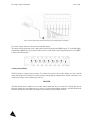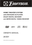
1
BUS
Fiber Optic Signal Conditioner
User Guide
MAN-00025 R6
If the equipment described herein bears the symbol, the said equipment complies with the applicable European Union Directive and
Standards mentioned in the Declaration of Conformity.
All rights reserved. No part of this publication may be reproduced, stored in a retrieval system, or transmitted in any form, be it
electronically, mechanically, or by any other means such as photocopying, recording, or otherwise, without the prior written
permission of FISO.
Information provided by FISO is believed to be accurate and reliable. However, no responsibility is assumed by FISO for its
use nor for any infringements of patents or other rights of third parties that may result from its use. No license is granted by
implication or otherwise under any patent rights of FISO.
FISO’s Commerce And Government Entities (CAGE) code under the North Atlantic Treaty Organization (NATO) is
L0294.
The information contained in this publication is subject to change without notice.
© 2006 FISO Technologies Inc.
Words that FISO considers trademarks have been identified as such. However, neither the presence nor absence of such
identification affects the legal status of any trademark.
Units of measurement in this document conform to SI standards and practices.
Fiber Optic Signal Conditioner
User Guide
Contents
Certification Information ..................................................... 5
1.
INTRODUCING THE BUS SYSTEM ............................................7
Equipment Overview .......................................................... 7
2.
SAFETY INFORMATION .........................................................11
Safety Conventions ........................................................... 11
Safety Information............................................................. 11
3.
GETTING STARTED WITH YOUR BUS SIGNAL CONDITIONER .....13
Unpacking and Inspection................................................. 13
Connecting the Interfaces.................................................. 13
Cooling and Installation..................................................... 15
4.
OPERATING THE BUS SIGNAL CONDITIONER ..........................17
Interfacing with the System ............................................... 17
Memory............................................................................ 17
Sampling Rate and Data Averaging.................................... 17
Acquisition Modes ............................................................ 18
Analog Output .................................................................. 19
Sensor Selection ............................................................... 20
Sensor Calibration............................................................. 21
Other System Functions .................................................... 22
5.
USING REMOTE CONTROL COMMANDS .................................23
Hardware Settings............................................................. 23
Remote Control Commands.............................................. 24
6.
FISO COMMANDER BUS VELOCE EDITION SOFTWARE ............26
System Requirements........................................................ 26
Instrument Accessibility with the Software ......................... 26
Getting Started with the FISO Commander BUS Veloce Edition.... 26
FISO Commander BUS Veloce Edition Overview .............. 29
7.
USING FISO COMMANDER BUS VELOCE EDITION SOFTWARE ..32
Establishing Communication with the BUS System Modules..........32
Configuring Sensors and Acquisition Parameters ................ 33
Acquiring Data through the RS-232 Port............................ 39
Configuring Analog Output Parameters ............................. 40
Acquiring Data through the Analog Output Ports ............... 43
8.
3
MAINTENANCE ...................................................................44
Preventive Maintenance.................................................... 44
Handling the Sensors ........................................................ 44
Cleaning a Fiber Optic Connector ..................................... 44
Cleaning Detector Ports .................................................... 45
Replacing the Fuse............................................................ 45
Replacing the Light Source ................................................ 46
Recalibrating the Unit ....................................................... 50
FISO
BUS
9.
TROUBLESHOOTING............................................................ 52
Auto-Diagnosis and Error Messages ................................... 52
Contacting the Technical Support Group........................... 53
Transportation .................................................................. 54
10. WARRANTY ........................................................................ 56
General Information ......................................................... 56
Liability ............................................................................ 56
Exclusions......................................................................... 56
Certification...................................................................... 56
Service and Repairs .......................................................... 57
FISO Service Centers Worldwide ...................................... 57
A.
TECHNICAL SPECIFICATIONS ................................................. 58
B.
REMOTE CONTROL COMMANDS FOR THE BUS SYSTEM ........... 60
Convention ...................................................................... 60
Error Codes ...................................................................... 60
Error String Syntax ............................................................ 60
Command Summary......................................................... 61
Data Acquisition ............................................................... 62
Analog Output.................................................................. 65
Memory ........................................................................... 65
Gauge .............................................................................. 66
Miscellaneous................................................................... 69
4
Fiber Optic Signal Conditioner
User Guide
Certification Information
F.C.C. Information
Electronic test equipment is exempt from Part 15 compliance (FCC) in the United States, but FISO makes reasonable efforts
to ensure this compliance.
Information
Electronic test equipment is subject to the EMC Directive in the European Union. The EN61326 standard prescribes both
emission and immunity requirements for laboratory, measurement, and control equipment.
This unit has been tested and found to comply with the limits for a Class B digital device.
Independent Laboratory Testing
This unit has undergone extensive testing according to the European Union Directive and Standards. Pre-qualification tests
were performed internally, at FISO, while final tests were performed externally, at an independent, accredited laboratory. This
guarantees the unerring objectivity and authoritative compliance of all test results.
This product is equipped with a detachable, shielded, three-wire power cord and plug. Use this power cord in conjunction with
a properly grounded electrical outlet to avoid electrical shock and to reduce radio frequency interference that may emanate from
the power cord.
Use of shielded remote I/O cables, with properly grounded shields and metal connectors, is recommended in order to reduce
radio frequency interference that may emanate from these cables.
Use of coaxial cable shorter than 3 m in length is recommended on all analog outputs for minimal noise on the DC signal.
5
This page intentionally left blank.
Fiber Optic Signal Conditioner
1.
User Guide
Introducing the BUS System
The BUS System is a fiber optic multi-channel signal conditioner for FISO's fiber optic strain, temperature, linear position &
displacement, force & load, and pressure sensors. This is the ideal instrument when multi-channel simultaneous recording is
required. Each independent channel of the BUS System has a 14-bit resolution (without averaging), with 15 000:1 dynamic
range while the overall physical dynamic range and resolution will depend on the type and sensitivity of the fiber optic sensor
used with the instrument. Each channel can acquire at a Sampling Rate of 100, 500, or 1000 Hz, and provides you with full
control over operating parameters. The following sections explain how to operate your BUS System.
Equipment Overview
Up to eight modules are assembled inside a19-inch rack mount casing. RS-232 serial communication with each module is
possible through the DB-9 connector installed on the front panel of the rack mount chassis.
Front Panel
BUS MODULE
COMMUNICATION PORT
Figure 1. Front panel overview of the BUS System
7
FISO
BUS
Back Panel
CERTIFICATION AND
AC ININPUT WITH
INTEGRATED SWITCH AND
WARNING LABEL
EXHAUST
FANS
FUSE HOLDER
ON
OFF
Figure 2. Back panel overview of the BUS System
Module Front Panel
The BUS module front panel essentially consists of the fiber optic sensor input connector (ST type), the analog output
connector (BNC type) and a Status LED.
IDENTIFICATION LABEL
STATUS LED
OPTICAL SENSOR CONNECTOR
ANALOG OUTPUT
CONNECTOR
Figure 3. BUS module front panel overview
8
Fiber Optic Signal Conditioner
User Guide
Status LED
A red Lamp-on LED indicates that the light source of the module is activated.
Sensor Input
The fiber optic sensor connects to the BUS module via the ST-type fiber optic connector.
Analog Output
The analog output gives a voltage proportional to the value of the physical parameter measured by the fiber optic sensor. The
analog output is a BNC-type coaxial connector. See section Analog Output, on page 19, for converting the voltage output
value to the measured physical parameter value.
9
This page intentionally left blank.
Fiber Optic Signal Conditioner
2.
User Guide
Safety Information
Safety Conventions
Before using the product described in this manual, you should understand the following conventions:
DANGER
Indicates a potentially hazardous situation which, if
not avoided, could result in death or serious injury.
Do not proceed unless you understand and meet the
required conditions.
WARNING
Indicates a potentially hazardous situation which, if
not avoided, may result in minor or moderate injury.
Do not proceed unless you understand and meet the
required conditions.
CAUTION
Indicates a potentially hazardous situation which, if
not avoided, may result in component damage. Do
not proceed unless you understand and meet the
required conditions.
IMPORTANT
Refers to information about this product you should
not overlook.
This symbol appears on the identification label at the
back of the unit. It refers to important safety notices
that can be found in this manual
This symbol identifies an accessible hot surface.
Safety Information
WARNING
Do not install or terminate fibers while a light source is active.
Never look directly into a live fiber and ensure that your eyes are protected at all times.
The level of radiation is below the level known to cause eye injury through accidental exposure. However, avoid prolonged
exposure to light emitted from the fiber and do not stare directly at a light beam, visible or not.
WARNING
Use of optical instruments with this product will increase eye hazard.
The following safety instructions must be observed whenever the BUS Fiber Optic Signal Conditioner is operated.
Failure to comply with any of these instructions or with any precaution or warning contained in the user guide is in direct
violation of the standards of design, manufacture and intended uses of the product. FISO assumes no liability for the
customer failure to comply with these safety requirements. THIS PRODUCT IS NOT DESIGNED FOR USE
LIFE SUPPORT OR CRITICAL APPLICATIONS.
11
FISO
BUS
In no case will FISO be liable to the buyer, or to any third parties, for any consequential damage or indirect damage which is
caused by product failure, malfunction, or any other problem.
When using any electrical appliance, basic safety precautions should be followed, including the following:
Verify that the AC voltage and frequency delivered at the power outlet are compatible with the instrument’s input power
specifications
Do not operate in wet/damp conditions
Do not operate in an explosive atmosphere
Keep product surfaces clean and dry
WARNING
This product must be used as specified or the protection provided by the equipment may be compromised. You must use this
product in a normal mode and should not deviate from the written instructions provided.
CAUTION
There are no user serviceable parts inside the BUS System, other than the ones specified in the Maintenance section.
Adjusting parts inside the unit can affect the accuracy of the instrument. If you adjust parts, you will need to verify the
accuracy of the measurements. Refer servicing of any other parts to qualified personnel.
12
Fiber Optic Signal Conditioner
3.
User Guide
Getting Started with your BUS Signal Conditioner
Unpacking and Inspection
The BUS Fiber Optic Signal Conditioner is packaged in a box designed to give maximum protection during shipment. If the
outside of the shipping box is damaged, notify your shipping department immediately. Your shipping department may want to
notify the carrier.
If the external shipping carton is not damaged, carefully remove and identify all of the components listed below. Contact FISO
or your local representative if any of the components are missing. We recommend you save the shipping carton for future storage
or transportation.
The BUS package should include the following components:
BUS main rack mount casing and as many modules as were ordered
Power supply cable
RS-232 cable
FISO Commander Bus Veloce Edition Software installation CD-ROM
Data Acquisition Station (optional package)
User Guide
Declaration of Conformity
Connecting the Interfaces
Before proceeding with product setup and use, read the safety information and instructions.
Power Input
WARNING
To avoid damage to the unit, and consequential voiding of the warranty, make sure that the power fed into the power port
complies with technical specifications power input range. No other voltage level or range is accepted.
Check to see that the line voltage is within the specified limits.
Before plugging in the power cord, make sure that the power switch is in the off (O) position.
Connect the female end of the supplied power cord to the AC receptacle on the rear panel.
Connect the other end of the power cord to a grounded AC outlet.
DANGER
The power cord supplied with the BUS System contains a separate ground wire for use with grounded outlets. When proper
connections are made, instrument chassis is connected to power line ground through the ground wire in the power cord. Failure
to use grounded outlet may result in personal injury or death due to electrical shock.
Turn on the instrument by pressing the rear panel power switch to the on (I) position.
At power on, the instrument turns on sequentially the lamp of each module. The red LED indicator shows that the lamps are
on. If the LED indicator of a channel does not turn on, the lamp might have to be replaced. Refer to section
Replacing the Light Source, on page 46.
13
FISO
BUS
CAUTION
Both the power cord and the AC main switch may be used as disconnecting device; make sure that they remain accessible at all
times after installation of the unit.
In order to minimize current bursts, modules are power-supplied sequentially when the conditioner is powered on. The lamp
turns on automatically at module power up. The front panel red LED indicates that the module is on and the lamp is working.
Make note that an additional preheating time of 1 second (100 Hz) to 5 seconds (500 to 1000 Hz) is required after module
activation to perform a reading.
Signal Input
CAUTION
To avoid misalignment and subsequent measurement errors, the fiber optic cable inside the unit that is connected to the SC-SC
connector should never be removed.
CAUTION
Use care in handling fiber optic connectors. Always clean the fiber end prior to insertion into the connector for optimum
performance and to avoid measurement errors.
To connect the sensor to one of the BUS System modules, simply mate the sensor fiber optic connector with the input connector
of the module. All FISO fiber optic sensors can be used with fiber optic extension cables. The length of the extension cables can
be up to 1 km long depending on the selected Sampling Rate.
For proper use of the fiber optic sensors, its connector must be kept clean and free of dust at all times. Any dust may obstruct the
light transmitted from one connector to the other, and reduce the signal-to-noise ratio to an unusable level. Wiping the end with
low lint tissue such as Kimwipes™ or lens cleaning tissues cleans sensor connector. By keeping your sensor connectors clean you
will also prevent the contamination of the instrument input connectors. However, we recommend cleaning the BUS System
input connectors once in a while. Use the specially designed 2.5 mm mini foam swab provided with the cleaning kit to clean the
input connectors of BUS System. It is a good practice to always clean the sensor interface before connecting it to the instrument.
In order to maximize the lamp lifetime, all unused channels should be deactivated. Note that lamps turn on automatically at
system power up.
Data Acquisition Station
The Data Acquisition Station — optional analog acquisition card and chassis — are available to make acquisitions through the
modules’ analog outputs. The acquisition card is a PCMCIA card that must be installed in your PC according to
manufacturer’s instructions. Please refer to the acquisition card user manual for installation and configuration.
The analog I/O chassis is the interface between the BUS modules and the acquisition card. It provides BNC connectors at the
input interface to connect directly from the modules analog output and a data link connector to convey the information to the PC
acquisition card.
14
Fiber Optic Signal Conditioner
User Guide
Figure 4. Connecting the Data Acquisition Station between the BUS System and the PC
For accurate readings, make sure your connections match these settings.
The software sets the analog inputs to DC coupling and non-referenced single-ended (NRSE) signals. To set the BNC-2090
terminal block to NRSE, the connector signal switches must be set to SE and the common signal switch must be set to NRSE,
as shown in the following figure.
Cooling and Installation
The BUS System is cooled by forced convection. Two exhaust fans located on the rear allow ambient air to flow inside the
casing of the instrument. The ambient air is drawn inside the casing through the ventilation louvers located on the bottom cover,
near the front, and goes out the ventilation fans at the rear.
CAUTION
The BUS System must be installed in an area where ambient temperature does not exceed 32°C. Enough space must be
allowed for exhaust fans and ventilation louvers so they are not obstructed and sufficient ventilation is provided. Operating the
instrument with improper cooling may cause damage to the instrument, possibly voiding the warranty.
15
This page intentionally left blank.
Fiber Optic Signal Conditioner
4.
User Guide
Operating the BUS Signal Conditioner
Interfacing with the System
Data and command communication with the BUS System is highly flexible, thanks to the available interfaces and the following
communication methods:
RS-232 remote control commands
FISO Commander Bus Veloce Edition
Data Acquisition Station
RS-232 remote control commands allow system configuration, sensor management, as well as data acquisition and downloading.
The remote control commands are explained in the next section and Appendix B is a detailed list of available commands. The
FISO Commander Bus Veloce Edition software handles all the system functions without having to type remote control
commands. Moreover, it manages the Data Acquisition Station configuration and data acquisition and download.
Memory
Each BUS System module has a non-volatile RAM type memory where all settings such as gauge factors, acquisition process
parameters, etc. are stored. When turned on, each module is initialized to the previous settings used. If for any reason the RAM
memory contents on a given module has been damaged or lost during operation, the module will be reinitialized to its default
factory settings. That means that all gauge factors in the sensor list and associated zeros will be lost. You may also reset the
RAM memory to its factory state by using the system reset [RW] command. Each BUS System module also has a non-volatile
ring memory buffer with a capacity of 4096 (4K) data points.
Sampling Rate and Data Averaging
The sampling rate of the BUS System modules can be separately set at 100 Hz, 500 Hz or 1000 Hz. You may select the
sampling rate according to the type of measurement that will be performed. Two important points must be noted:
According to the Nyquist theorem, the sampling rate limits the bandwidth of the signal recorder by the BUS System
A higher sampling rate reduces the signal-to-noise ratio.
The first point means that the BUS System modules cannot integrally record a dynamic physical phenomenon up to the
frequency limit given by the Nyquist sampling theorem. The second point is due to the fact that the integration time of the light
detector gets smaller at higher sampling rates, reducing the amount of light measured by the detectors during one data
measurement. This is why we recommend using the lowest sampling rate whenever possible.
You can set the averaging time for each module individually. The data averaging depends on the sampling rate setting. For
example and assuming that the BUS System module has a 1000 Hz sampling rate, an averaging time of 10 ms will result in
averaging of 10 samples since the time interval between two consecutive samples is 1 ms (1/1000 Hz).
17
FISO
BUS
Acquisition Modes
Four different acquisition modes are available to adapt data acquisition to your test requirements:
Normal mode
Triggered mode
Variable mode
Manual mode
The acquisition is done accordingly to the values set with the acquisition average and rate commands. Data is sent in standard
ASCII characters with a line feed and carriage return character after each value. A header is included on the top line to indicate
the gauge factor for which the data was acquired. The data samples in the memory buffer can be downloaded to the computer
with the data download command. Downloading these data points resets the buffer and data sent is erased from the module’s
memory.
Normal Mode
When operated in the normal acquisition mode [TM0], which is the default state, the acquisition starts as soon as the command
is sent. The buffer length must be set between 1 and 4096 points with the buffer length [TB XXXX] command. The memory
buffer is circular and works in wrap-up mode, where it is first filled with data and then wraps around to start over and overwrites
the previous values.
Triggered Mode
When set in triggered mode [TM1], the BUS System works exactly as in continuous mode, except that the trigger command
[TSX] must be sent before the acquisition starts. The buffer is circular and it must be set between 1 and 4096 points,
according to the desired number of data points, with the buffer length [TB XXXX] command.
Variable Mode
When using the variable mode — [TM6] to [TM4096] — the buffer length adjusts automatically to the number of data
points defined in the acquisition mode [TMX] command. The acquisition starts as soon as the command is received and stops
when the number of data samples has been reached. The module indicates the acquisition has stopped with the message READY
through the RS-232 link. Next acquisitions can be started with the trigger [TSX] command. Note that the buffer length will
remain set to the length given with this command until it is reset with the buffer length [TB XXXX] command.
Manual Mode
In the manual mode [TM5], the acquisition starts with the trigger [TSX] command. In this mode, you must adjust the buffer
length be to the necessary data points with the buffer length [TB XXXX] command. Once the buffer has been filled with data
points, the acquisition stops and the message READY is sent through the RS-232 link.
18
Fiber Optic Signal Conditioner
User Guide
Analog Output
The BUS conditioner has a voltage analog output for each of its measuring channels. These outputs have a full scale range of ±
10 Volts with a resolution of approximately 1.22 mV. The analog outputs are updated at the same rate of the data
measurements. For each of the outputs, you have control of both the analog scale factor (mV per Physical Unit) and the analog
offset (the value of the data measurement M at which the analog output voltage is zero). The analog output voltage is
proportional to the data measurement obtained from the sensor. It is given by the following equations:
Vout = SCALE × (M − ZERO)
(Volts)
where:
SCALE is the analog scale factor in mV/physical units
M is the data measurement obtained by the conditioner
ZERO is the analog offset
With FISO Commander Bus Veloce Edition, you can adjust the analog scale factor and analog offset (zero) parameters for
each analog output to cover the entire range of the instrument. However, for highest resolution, use the highest possible analog
scale factor. The voltage range of the output can be determined by using the above equation and substituting in the highest
measured value of M, and lowest measured value of M. The analog output of the signal conditioner is adjusted at the factory
with default setting values which depend on the type of the sensor (the analog offset default value is always zero). The following
table gives the analog output default setting values for different type of sensors along with the corresponding range and
resolution.
Sensor type
Strain
Temperature
Pressure
Load
Displacement
Internal unit
(nm)
Default settings of the ± 10 Volts analog output
Analog Scale Factor
Analog Offset
Range
Resolution
(scale)
(zero)
SI
Imperial
SI Imperial
SI
Imperial
SI
Imperial
± 5000 ± 5000 με 0.6 με 0.6 με
2 mV/με
2 mV/με
0 με 0 με
με
± 1000 ± 1000 °F 0.12 °C 0.12 °F
10 mV/°C
10 mV/°F
0 °C 0 °F
°C
± 133 bar ± 2000 psi 0.016
0.24 psi
75 mV/bar
5 mV/psi
0 bar 0 psi
bar
2 mV/kg
1 mV/lb
0 kg 0 lb
± 5000 ± 10000 0.6 kg 1.22 lb
kg
lb
0 in
± 20 mm ± 1 in
2.4 μm 0.12 μ500 mV/mm
10000 mV/in 0
mm
in
1 mV/nm
0 nm
± 10000 nm
1.22 nm
To restore the analog scale factor and the analog offset to their default value, set the scale parameter to zero.
Assigning another gauge factor from the sensor list (i.e. selecting another sensor) will restore the analog scale factor and the
analog offset to their default values only if this sensor is of a different type than the previously assigned one. In other words,
selecting another sensor but of same type will not change the analog output settings.
19
FISO
BUS
Sensor Selection
Gauge Factor
Before a sensor can be used with the BUS System modules, its gauge factor must be stored in the module memory. Each BUS
System module can store up to 50 gauge factors in its internal sensor list. The module uses the gauge factor to identify the sensor
type and its factory calibration factor. The modules come with the default gauge factors 0001000 (or 1000) and 0 already
stored in the memory. To add a sensor, enter its gauge factor in the module memory via the FISO Commander Bus Veloce
Edition interface or with the sensor add [ASxxxxxxx] remote control command. When a sensor is no longer in use, it can be
removed from the sensor list via the software interface or with the sensor erase [RSxxxxxxx] remote control command.
The gauge factor is located on a label close to the sensor fiber optic connector. The first digit of the gauge factor corresponds to
the type of sensor used as indicated below, 0 is the default number and is not associated to any type of sensor:
1
2
3
4
5
non-compensated strain sensors
pressure sensors type 1
force & load sensors type 1
temperature sensors type 1
compensated strain sensors
6
7
8
9
pressure sensors type 2
force & load sensors type 2
linear position & displacement sensors
temperature sensors type 2
The second digit is used to differentiate sensors of same type and sensitivity. For strain, force & load, and pressure sensors: the
third digit is used to increase the gauge factor one decade per digit increase while the last four digits correspond to the sensor
scale factor. In the case of the linear position & displacement sensor, the last five digits correspond to its sensitivity. In the case of
the temperature sensor, the last six digits correspond to the factory calibration values.
Selecting a Sensor
To use a sensor with the BUS System modules, you must select its gauge factor in the sensor list, either through FISO
Commander or with the gauge select [GAxxxxxxx] command. The Gauge factor 0001000 is default number selected by the
module. Note that, whatever the sensor type connected to the module, if the selected gauge factor is 0001000, the module will
read the sensor cavity length in internal units. The BUS System internal unit of measure is the nanometer. The content of the
sensor list may be seen through FISO Commander or downloaded using the gauge list [LG] command.
20
Fiber Optic Signal Conditioner
User Guide
Sensor Calibration
FISO's fiber optic sensors come with their sensitivity or gauge factor already calibrated at the factory. For an adjustment, you
may just define a zero or an offset point using the zero internal [ZPxxxxxxx] or zero physical [ZOxx.xx] remote control
commands or through FISO Commander.
IMPORTANT
The temperature sensor is a special case where both the gauge factor and the zero point have been already calibrated at factory
so you should not have to make any adjustments.
Nulling a Sensor
All types of sensors can be nulled at any time and it is recommended to null strain and pressure sensors at least once. A sensor
can be nulled through FISO Commander or by sending the zero physical [ZOxx.xx] remote control command with 0 as the
parameter. After nulling, the module will indicate a sensor reading of zero or a very small value. The sensor should not be
submitted to strain (for strain sensors) or pressure (for pressure sensor) if you want to obtain a true zero.
Note: Before the first sensor nulling, we recommend to take note of the current zero value, in internal units, of the selected
sensor (i.e. this number will correspond, after nulling, to the cavity length of the sensor in nm at which the module
indicates a zero value). This may be useful for long term measurements where you want to keep a record of your sensor
true zero. The actual zero value can be read with the zero download [ZD] command.
IMPORTANT
The temperature sensor, which is fully calibrated at the factory, must not be nulled for proper operation. The linear position and
displacement sensor should not be nulled either for best precision.
Sensor Offset
The zero physical or zero internal functions are used to null or to add an offset value to the selected sensor in physical
(engineering) units or in internal units (nm), respectively. With the zero physical function, the offset value entered is compatible
with the physical units of the selected sensor. With the zero internal function, the offset value is in nanometers. This last
command can be useful to re-enter a zero value which was lost from an instrument reset or a memory loss and another good
reason to keep a record of the sensor zero value. Right after receiving the zero physical or zero internal command, the module
will indicate a sensor reading corresponding to the physical or internal offset value.
21
FISO
BUS
Other System Functions
Diagnostic Function
The system’s diagnostic report provides important system performance information for diagnostic purposes. This function can be
useful to evaluate the performances of both the instrument modules and the fiber optic sensors. The system provides information
on the gain and the raw signal.
The raw signal measures the amplitude of the light power detected by the module. It provides light source failure information
and helps detect improper connections.
The gain provides information on the amplitude of the interferometer signal coming from the fiber optic sensor. It provides
information on the sensor itself.
The following table gives the numerical values of these signals depending on the system conditions.
Note: Diagnostic results are significant only when the system sampling rate is set to 100 Hz.
Signal
RAW
GAIN
Sampling Rate
100 Hz
100 Hz
Defective
< 2.1 V
> 80 %
System condition
Poor
2.1 to 3.5 V
60 - 80 %
Good
> 3.5 V
< 60 %
Referring to the above table, you can make a diagnosis on instrument and sensor set-up performance.
Auto-Diagnosis and Error Messages
Each module of the BUS System is equipped with an auto-diagnosis feature that can detect a defective or noisy measurement
condition, including the fiber optic sensor setup.
Using check sum error values based on the amplitude of the raw signal and the gain, the module sends different messages
through the RS-232 link, in case of defective or noisy measurement conditions.
Note: The auto-diagnosis is only available when the module has a sampling rate of 100 Hz. The auto-diagnosis feature can be
enabled (default state) or disabled using the auto-diagnosis on and off commands.
22
Fiber Optic Signal Conditioner
5.
User Guide
Using Remote Control Commands
Each BUS System module can be controlled independently via the RS-232 serial link with the RS-232 remote control
commands described in the following sections and in Appendix B. The measurement output can be obtained through either the
± 10V analog output or through the RS-232 serial link. The analog output provides immediate results, while through the
RS-232 link, data must be downloaded once the acquisition session is over.
Hardware Settings
The RS-232 serial connection to the BUS System is made through a DB-9 connector located on the front of the rack mount
chassis. The BUS System is equipped with a RS-232 internal switch to give access to each module from one single RS-232
serial link.
If your computer is equipped with a DB-9 serial port connector, then use a standard RS-232 extension cable (all wires straight
through). If your computer is equipped with a DB-25 connector, use a DB-25 to DB-9 converter module with a standard RS232 extension cable.
Note: Do not use a null modem cable or adapter.
The serial link must be configured as follows:
Baud rate:
Parity:
Data bits:
Stop bit:
9600
none
8
1
Hardware Flow Control
The BUS System instrument makes use of hardware flow control, also called handshaking, based on RTS/CTS control. When
activated, the Request To Send (RTS) line of the serial link informs the BUS System that the UART of the host computer or
controlling instrument is ready to exchange data. The Clear To Send (CTS) line indicates, when activated, that the BUS
System is ready to exchange data.
IMPORTANT
In BUS Systems that were built on or prior to 2004, the handshaking is based on DTR/DSR control, instead of RTS/CTS.
To find out how system hardware flow control is configured in your unit and how to adapt to the changes, you must contact
FISO Technical Support and provide the unit’s serial number.
RS-232 Switch
The BUS System is equipped with two cascaded RS-232 switches to give easy access to any of the eight plug-in modules from
one single RS-232 connector. It is required to first establish the link between the DB-9 connecting port and the module with
which the communication needs to be established. Once the communication is established, then commands can be sent and
received between the host computer and the selected module. The switch looks continuously for a four character code by
monitoring the data that is being received from the host computer. The switch requires a four-character preamble code to turn a
port on and off. The first character must be the ASCII escape character (decimal 27). The second character is the ASCII
character STX (decimal 2). The third and fourth characters are used to select the port associated to the proper module. The
commands required to establish the connection to each module are given in the table below. Once the connection is established,
the remote control commands are sent to the selected module and data is received from it for as long as the switch does not catch
a new command to establish a new connection.
23
FISO
BUS
Selected Module
1
2
3
4
5
6
7
8
Module 8
Module 7
Module 4
Module 3
BE
BD
AE
AD
BA
BB
AA
AB
Module 5
Module 6
Module 1
Module 2
ASCII
switching command
ESC STX AA
ESC STX AB
ESC STX AD
ESC STX AE
ESC STX BA
ESC STX BB
ESC STX BD
ESC STX BE
RS-232
Link
Keyboard
switching command
ESC Ctrl B AA
ESC Ctrl B AB
ESC Ctrl B AD
ESC Ctrl B AE
ESC Ctrl B BA
ESC Ctrl B BB
ESC Ctrl B BD
ESC Ctrl B BE
Remote Control Commands
All the remote control commands can be sent to the BUS System by using simple communication software (such as
HyperTerminal® or MLINK®). These commands can also be used with programs made with BASIC, C/C++ compilers, or
with third party software such as ASYST or LAB-VIEW.
All remote control commands begin with a two letter (capital letter) identifier referred to as the prefix of that command.
Commands without argument are composed solely of their prefix. All commands must start with a left bracket ( [ ) and end with
a right bracket ( ] ) to be interpreted correctly. These two characters are the delimiters of a command. Everything typed inside
the bracket is considered to be part of the command. Whenever a command must be followed by an argument, the command
prefix and the argument are strung together. The BUS System does not interpret a command until the right delimiter is
encountered in the incoming flow of characters. Everything between the brackets is sent back over the serial link as soon as the
right delimiter is encountered. In other words, all command sent to the BUS System is echoed back to the computer. You will
notice that that the BUS System modules take more time to respond (i.e. to sent the echo back) at 500 and 1000 Hz Sampling
Rate than 100 Hz. This is not an abnormal situation so it is important to wait for the echo of the BUS System before sending
another command. Each line of characters returned to the computer by the BUS System terminates with a line feed (LF) and
carriage return (CR) character. Note also that each string of characters on same line is normally separated by one space
character identified by a normal space in this manual.
Example: The command [SN] sends the unit serial number. Upon reception of the command, the BUS System returns the
following over the serial link: [SN]SNLFCR 02BC1044LFCR. For a complete description of each command see Appendix
B.
24
Fiber Optic Signal Conditioner
User Guide
This page intentionally left blank.
25
FISO
6.
BUS
FISO Commander BUS Veloce Edition Software
The FISO Commander Bus Veloce Edition Software is designed to configure the BUS System and retrieve all the data stored
in the unit. It is possible to communicate directly through the RS-232 port of the unit and control the modules for direct, realtime acquisitions.
The software includes several functionalities which will assist the user with system setup and data acquisition. By controlling all
the parameters and changing one parameter at a time, the software makes your system easy to operate. It is user-friendly and
provides an interesting visual support for data analysis.
Here is a list of actions you can perform with the FISO Commander Software:
Configure the sensors from your computer
Make a new calibration for a sensor
Proceed to a real-time acquisition session
Save the data in a format to be used in a commercial spreadsheet program
System Requirements
Minimum requirements:
Intel® Pentium® II or compatible processor at speed above 233 MHz
Microsoft Windows® XP or 2000
Monitor resolution at 800 x 600
At least 64 MB of RAM and 20 MB of available hard disk space.
CD-ROM or DVD-ROM drive
A mouse or similar pointing device.
Instrument Accessibility with the Software
You can use the software directly with a serial cable between your PC RS-232 port and the BUS System for configuration or
data retrieval.
Getting Started with the FISO Commander BUS Veloce Edition
Installing the Program
To install the software on the computer:
1.
2.
Place the installation CD-ROM provided with the system on the CD-ROM drive. If the installation software does not
start automatically. Execute Launch.exe from the CD-ROM root directory.
Select Setup from the column to the left of the Welcome screen.
26
Fiber Optic Signal Conditioner
3.
User Guide
Click on National Instruments (NI-DAQ) drivers…
Note: At the time of driver installation, it is important that the card is not inserted in the computer.
4.
5.
6.
7.
8.
9.
10.
11.
27
Follow the on-screen instruction to install the drivers.
Insert the National Instruments Data Acquistion Card in the computer.
Click on Install FISO Commander Bus Veloce Edition. The InstallShield Wizard will automatically start.
Click on Next to proceed with the installation.
Follow the wizard instructions on screen.
When the installation is over, click on Finish to exit the wizard.
From Window’s Start menu, select Measurement & Automation Explorer or double-click on the icon from your
desktop.
Browse the configuration panel until you find the name of the card you have inserted in the computer.
FISO
BUS
12.
Right-click on the name of the card and select Test Panel from the pop-up menu.
13.
Click on Close and exit the Measurement & Automation application.
Your software is ready to use.
Accessing and Exiting the Program
The FISO Commander Bus Veloce Edition should be in the installed program list, under Fiso Technologies. To execute the
program, select the program from the program list.
After loading the software, FISO Commander Bus Veloce Edition, you must establish the communication with the conditioner
to proceed with the initialization process. This process consists of reading all the default parameters values stored in the BUS
modules memory (serial number, hardware version, etc.).
To exit the program, click on the button to close the window, on the right top corner of the application window.
28
Fiber Optic Signal Conditioner
User Guide
FISO Commander BUS Veloce Edition Overview
Going from one window to another is done by selecting the required item from the navigation tree on the left-side panel. The
right side panel will change according to the selection and the different functions will be available for configuration and system
operation.
For the BUS System, four main right-side panels are available:
Initialize
Configuration
RS-232
DAQ Card
Each of these panels will be explained in the following sections.
Initialize Panel
When you open the software, the first information that displays is the Initialize panel. From here, you must establish a
communication link with the desired unit. The information for each detected module in the unit will display on a line of the
table.
29
FISO
BUS
The Auto-detect modules function takes the guessing out of unit configuration. All modules present and properly installed in the
BUS System report to the software and provide their serial numbers, product versions, and, by clicking on the corresponding
Diagnostics table cell, self-diagnostic information.
Configuration Panel
The configuration panel regroups all the corresponding sensor parameters for each detected module. Sensors are individually
assigned to each module and sensor information is saved in the module’s memory. It is from this window as well that you
configure analog output parameters, select the units of measurement, and turn the module’s lamp on or off.
30
Fiber Optic Signal Conditioner
User Guide
RS-232 Panel
In the RS-232 main panel, you may visualize the acquisition parameters for each detected BUS module. These parameters are
selected on the Configuration panel. It is from this screen that you start an acquisition session for any module when you use the
RS-232 link to download data. BUS modules acquire information individually and store the data in their own internal memory
until it is downloaded to your PC via the BUS unit’s RS-232 port. Acquisition parameters also display on this screen.
DAQ Card Configuration Panel
Acquired data can be sent through the modules analog output ports to an analog acquisition system. This is done by installing
the optional Data Acquisition Station and connecting the modules outputs to the analog input connectors of the analog I/O
chassis. The data output of this chassis connects to the acquisition card to retrieve information as it is generated on each module.
The Analog Card & Channel Configuration screen regroups all the information and functions pertaining to analog channel
acquisition and file management.
31
FISO
7.
BUS
Using FISO Commander BUS Veloce Edition Software
The following sections will explain, step by step, how to proceed with the configuration, data acquisition, and file management
with the BUS Signal Conditioner. The main requirements are to have a BUS unit connected to the PC where FISO
Commander is installed and all the required modules inserted in place with their sensors assigned for the configuration and direct
acquisitions. If the optional analog acquisition card and I/O chassis are available and installed, make sure all the necessary
analog outputs are correctly connected and that the data link is made for data transfer to the PC.
Establishing Communication with the BUS System Modules
Once the BUS System is connected to the PC, you may start by establishing a connection link with the desired module.
To do so:
1.
2.
3.
Open the FISO Commander Bus Veloce Edition application according to instructions on page 28.
Select the COM port to which the BUS Signal Conditioner is connected.
Click on Auto-detect modules.
All installed modules will display a line in the table, indicating in which slot they are.
4.
Verify that the information is correct and that all the modules have been detected.
Note that the table below the Auto-detect modules button will populate with the available COM ports and the type of unit
that have already been detected on those ports. This table may be used as a short-cut for future connections. When you select a
unit from this list, the current information will appear in the table to the right. You may also delete individual units or the whole
list if connection configuration has changed.
Before proceeding with the tests, you may wish to review module status to make sure they are working properly. To do so, for
each module, click on the corresponding Diagnostics table cell and an information pop-up will display module status.
32
Fiber Optic Signal Conditioner
User Guide
The RAW signal measures the amplitude of the light power detected by the module so it provides information on failure of the
light source and improper connections. The GAIN provides information on the fiber optic sensor by detecting the amplitude of
the interferometer signal coming from the sensor.
The following table gives the numerical values of these signals depending on the system conditions. Note that these diagnostic
results are significant only when the system Sampling Rate is set to 100 Hz.
Signal
RAW
GAIN
Sampling Rate
100 Hz
100 Hz
Defective
< 2.1 V
> 80 %
System condition
Poor
2.1 to 3.5 V
60 - 80 %
Good
> 3.5 V
< 60 %
Configuring Sensors and Acquisition Parameters
Once connection has been established and all modules have been detected to be working properly, you may proceed with sensor
configuration. It is important to know that sensors are individually assigned to BUS modules and they are not interchangeable
once they have been configured. The information for all sensors that have been configured for a particular module remains in the
module’s memory for future use. Configuration of a sensor for a given module is done only once.
The sensor parameters that you must configure before proceeding with an acquisition are the gauge factor, the zero value, and
the offset. The gauge factor identifies the sensor and is used in the calculations. The offset is a value that sets the zero
measurement, or signal baseline, at a specific signal level.
33
FISO
BUS
Configuring the Gauge factor
To configure a new gauge factor, proceed as follows:
1.
Under the Bus folder, in the navigation tree on the left side panel, select Configuration.
2.
Select the Gauge factor table cell of the module you wish to configure. The Gauge factor pop-up will display.
3.
Type the new gauge factor in the New gauge text box.
IMPORTANT
Pay attention not to confuse the gauge factor with the sensor serial number.
4.
5.
6.
Click on Add.
Continue adding gauge factors by repeating steps 3 and 4.
When you are done adding gauge factors, click on OK.
If you wish to select an already registered sensor gauge factor from the list,
1.
2.
3.
Select the gauge factor cell of the module you wish to configure. The Gauge factor pop-up will display.
Select a gauge factor that has already been configured from the list.
Click on OK.
34
Fiber Optic Signal Conditioner
User Guide
If, for any reason, you wish to delete a gauge factor from the list:
1.
2.
3.
4.
Select the gauge factor cell of the module you wish to configure. The Gauge factor pop-up will display.
Select the gauge factor you wish to delete from the list.
Click on Remove selected.
Click on OK.
Every time you click on OK, the information is directly sent to the BUS module being configured.
Configuring the Sensor Offset
The offset value shifts the readings as many units as selected. It sets a relative zero measurement, or relative signal baseline, at a
specific, user-selected, signal level. The offset can be applied using two different measurement units.
Internal units: a value specific to the sensor, generally in nm, equivalent to its zero value. Setting an offset value using the
internal units shifts the reading — in nm or counts, depending on the sensor type..
Physical units: the measurement value, entered in engineering units. The offset value is converted into internal units and
sent to the module.
Note: When using physical units to offset the readings, the module returns the offset in internal units and the physical value
cannot be recovered once it is applied.
To apply an offset to the readings:
1.
Under the Bus folder, in the navigation tree on the left side panel, select Configuration.
2.
Select the Offset table cell of the module you wish to configure. The Offset pop-up will display.
35
FISO
3.
4.
5.
BUS
Select the radio button of the type of units you wish to use to establish the offset.
Type the offset value, according to the type of unit selected, in the corresponding text box.
Click on Apply to send the information to the module and continue applying different offset values or click on OK to save
the information to the module and go back to the Configuration panel.
Note: When setting an offset in internal units, whether nm or counts, it is important to know that the scale factor (number of
physical units/nm or ct) is considered according to the following equation: Displayed results = (Reading − Offset) ×
Scale factor.
Configuring the Analog Scale Factor and Analog Zero
The analog scale factor establishes the relationship between the readings, in physical units, and a voltage level for the analog
output. The analog output ranges from -10 V to + 10 V. However, you are not forced to use the whole span for your
measurements and you can set a shorter range for your measurements. To configure the analog output, two methods are
available:
Manually: you specify how many mV correspond to a 1-unit signal change, in physical units.
Calculated: you may specify a minimum and maximum output voltage and a physical unit minimum and maximum values.
The software will calculate the corresponding scale factor.
The following table lists the default analog scale values for the different sensors:
# of
sensor
0
Sensor Type
Metric
Imperial
No type sensor
1&5
2&6
3&7
4&9
8
Strain sensor
Pressure sensor
Force sensor
Temperature sensor
Displacement
1
mV/nanometer
2 mV/μstrain
75 mV/Bar
2 mV/Kg
10 mV/°C
500 mV/mm
1
mV/nanometer
2 mV/μstrain
5 mV/Psi
1 mV/lbs
10 mV/°F
10 000mV/inch
The analog zero value establishes the measurement baseline for the analog output. It correlates a reading, in physical units, with
a zero-volt analog output.
36
Fiber Optic Signal Conditioner
User Guide
To set a scale factor:
2.
Under the Bus folder, in the navigation tree on the left side panel, select Configuration.
Select the Analog output table cell of the module you wish to configure. The Analog scale factor pop-up will display.
3.
Select the radio button according to the method you choose to set the scale factor.
1.
If you choose the manual method:
a) Type in the value, in physical units, that you wish to correlate to a zero-volt analog output reading.
b) Type the scale factor in the corresponding text box.
If you choose the calculated method:
Type a value, in physical units, corresponding to the input value at the time of nulling. See section Nulling a Sensor, on
page 21, for more information.
b) Specify minimum and maximum input values, in physical units.
c) Specify minimum and maximum output voltage values.
a)
4.
Click on OK to send the information to the module and exit the function.
The Show Formula button displays a new window with an explanation on how to interpret analog output readings:
37
FISO
BUS
Configuring Acquisition Speed and Refresh Rate
Acquisition speed and refresh rate are related parameters. They are configured simultaneously and changes to one affect the
other, as well as the acquisition rate. The acquisition speed represents the rate at which the module acquires data. Three speed
levels are available:
100 Hz
500 Hz
1000 Hz
To configure the acquisition speed,
1.
2.
Click on the table cell corresponding to the module you wish to configure.
Select the acquisition speed from the drop-down list.
The acquisition speed selection has an impact on the acquisition rate and the refresh rate according to the following relationship:
Speed
(Hz)
1000
500
100
Refresh rate
(min)
0.001
0.002
0.01
Acquisition rate
(min)
0.001
0.002
0.01
Both the speed and the refresh rate apply to the analog outputs and the RS-232 acquisition. The acquisition rate affects only the
speed at which data will be stored in the module buffer for later download during an RS-232 acquisition.
Selecting Measurement Units
Both SI and Imperial units of measurement are available to display the signal conditioner’s readings. To select a system:
1.
2.
Under Module Bay, select the module, for which you need to select a measurement unit.
Click on your choice of measurement units from the drop-down list in the Units column.
If you want the selected module’s current sensor exposure to become the zero position (in physical units), simply click on the
Null button.
The Reset button reinitializes the memory content of the selected BUS module to the default state values.
38
Fiber Optic Signal Conditioner
User Guide
Activating and Deactivating a Module
Module activation or deactivation is done by turning its lamp on or off, respectively. Turning the lamp off when the module is
not in use preserves its life expectancy.
Acquiring Data through the RS-232 Port
In the RS-232 panel, you must configure the number of data points per acquisition and the acquisition rate for each module that
was previously configured in the Configuration panel. Note that the number of data points is limited to a maximum of 4096.
The data is stored in a circular memory, so the system will store data continuously until the acquisition is stopped.
To proceed with an RS-232 acquisition session:
1.
2.
3.
4.
In the Nb data field, set the number of desired data points for the acquisition. The approximate delay for the acquisition
is shown.
In the Acquisition rate column, select the acquisition rate, in seconds, for the module.
To start the acquisition, press the Start button.
To display the results, press the Display button.
The Download BUS Data screen will open. It contains the current module configuration, for quick reference.
39
FISO
5.
BUS
To obtain the data that was stored in the module’s memory, click on Download.
The download time may take up to 5 minutes. For measurement verification and faster download, simply reduce the number of
data collected in the previous windows.
6.
To save the downloaded data into tab separated values file, click on the Save button. You may choose the folder where
you want to save the acquisition file. You may open this file later with a spreadsheet program such as Excel for further
analysis.
Note: The module configuration information is the most recent information that has been sent to the module. If you change
module configuration between the time of the acquisition and the time of data download, it might not correspond to the
parameters that were used for data acquisition.
7.
To return to the previous panel, press the Back button.
Configuring Analog Output Parameters
The analog acquisition features integrated in FISO Commander Bus Veloce Edition, are available only if you purchased the
Data Acquisition Station optional package.
If you purchased the Data Acquisition Station, the laptop provided will be preconfigured at the factory.
If, for whatever reason, the software ever needs to be registered again:
1.
2.
3.
4.
In the menu bar, select Help.
Click on About to display the software information popup.
Click on the Register button under the version number.
A registration window will appear allowing you to enter the NI-DAQ Card registration number, provided with your
package.
40
Fiber Optic Signal Conditioner
User Guide
Once the analog card has been registered, you will have access to the following panel:
Selecting the AO Card
This box provides information from the National Instrument Card. If you are using several acquisition cards, make sure to select
the proper one that corresponds to the BUS System that is being used.
IMPORTANT
Several National Instruments cards are available but only a few are supported by FISO Commander. Please contact FISO to
help you choose a card that corresponds to the required measurement resolution and speed.
Configuring Acquisition Parameters
In the Acquisition Configuration (Chart) group, you may select:
The acquisition speed from the drop-down list, up to 10 kHz. The acquisition speeds available correspond to the
acquisition card in your system.
The acquisition duration by typing the time in the text box and selecting the time units from the drop-down list.
Whether or not you wish to plot a graph during the acquisition.
41
FISO
BUS
Configuring Channels
This box contains all the settings for the real time display function available. For each channel, the user may assign a precise
color. According to specific needs, one specific channel can be enabled or disabled by adding and removing the checkmark.
When checked, the Bus module bay association will recall the corresponding setting to save module configuration in the
text file.
Configuring Files
This box contains all the settings for generating a text file. In the text file, the data will display in columns. Each column contains
data corresponding to one channel/sensor. For easiest export to Excel®, we recommend to separate the columns by a tab, and to
separate the decimals with a dot. This configuration makes exporting to a spreadsheet software easy to perform.
During the acquisition, the system generates a binary file that is unreadable. Its name is the selected file name that finishes by a
“~”, for example “Filename.txt~”. When the acquisition is finished or when the user clicks on Stop button in the graph
window, the generated file is post-processed (all information are converted into ASCII characters and the binary file is deleted).
In the case where the software communication fails during the acquisition, the generated file is not post-processed and its name
finishes by a “~”, this indicates that the file is still in binary form. The user can then launch the post-processing by clicking on
the File Recovery button to obtain the text file for the acquisition.
Before beginning an acquisition proceed as follows to configure the output file:
1.
2.
3.
Assign an output folder to the generated text file by clicking on the ellipsis […] button and browsing your network.
Select the file parameters, column separator and decimal separator.
Select whether you want to name the file yourself or you want the file to be named automatically.
42
Fiber Optic Signal Conditioner
User Guide
If you select Ask for Filename, the software will ask for a filename once the user presses Select File before beginning an
acquisition. The file will be saved in the folder specified by the user. The Automatic Filename generator prevents to overwrite
an existing file. The filename will be generated from the date and time of the acquisition.
Acquiring Data through the Analog Output Ports
Once all the parameters have been configured, you may begin an acquisition session from the Chart panel.
To perform an acquisition using the analog outputs:
1.
2.
Select Chart from the navigation tree.
Configure the voltage axis by selecting the appropriate radio button.
Automatic adjusts the voltage axis as data is plotted.
Manual lets you specify the upper and lower limits of the voltage axis and these values remain fixed during the acquisition.
3.
4.
5.
43
If Ask for Filename was selected during file configuration, a Select File button will appear at the bottom of the graph.
Click on this button to open the Save As window and select a folder for your data file.
Click on Start to begin the acquisition.
Click on Stop to end the acquisition session.
FISO
8.
BUS
Maintenance
Preventive Maintenance
At any time, follow the general recommendations regarding ESD safety. When handling optical fiber and fiber optic connectors
as well as for cleaning a fiber optic connector, follow the general recommendations of this section.
Inspection
The unit should be inspected regularly to detect wear, damage or missing parts and to ensure that the mounting screws or
brackets are not loose.
The power cord should be inspected as well to ensure that the female part is clean of dirt or any other substance that could
otherwise become conductive or hazardous, that the male terminals do not show sign of crack, bend or corrosion and that the
plastic insulation is not damaged.
Any non-conformity detected on the unit or the power cord should be reported immediately to qualified personnel or to FISO's
Technical Support.
Cleaning
The unit should be cleaned regularly to avoid excessive build-up of dust or any other potential contaminant.
To clean the unit, use a soft cloth dampened with soapy water. Make sure that no liquid drips from the cloth that could
introduce moisture inside the unit.
Handling the Sensors
Read the following precautions prior to installing and when using sensors:
Avoid sharp bending radius in the fiber optic cable (< 10 mm).
Avoid tension, pinch points or twisting of the fiber optic cable.
Do not pull on fiber optic cable to clear tangles; instead, carefully unwind.
Do not allow the fiber optic connectors to drop or scrape on hard surfaces.
Keep the surface of the fiber optic connector clean.
Always use protector caps on the fiber optic connectors when sensors are disconnected from the signal conditioner.
Cleaning a Fiber Optic Connector
To make good optical measurements, it is extremely important to clean the fiber optic connector before each connection. Dirt on
the connector can degrade the reliability of the measurement and cause permanent damage to the connector resulting in an
expensive repair.
Modern fiber optic connectors rely on a glass-to-glass contact to reduce Fresnel reflections at the connector interface. A dirty or
damaged connector on the cable can damage the input connector. Always use a good quality cable connector. If there is any
question of the surface quality on the tip of the cable connector, inspect it under a microscope for scratches or debris.
44
Fiber Optic Signal Conditioner
User Guide
Some general recommendations:
Never use a metal or other hard object for cleaning that would scratch the ferule.
Do not apply index-matching gel or oils.
Always keep connectors covered for protection when not in use.
To clean the end of the connector on the fiber optic cable:
1.
2.
Gently wipe the tip with a lint-free swab, Optic Prep™ pad or lens paper dipped in 99% isopropyl alcohol.
Dry it by wiping gently with a clean dry lint-free lens paper.
As soon as the connector is dry, insert it in the panel or cover it for later use.
Cleaning Detector Ports
It is equally important, to make good optical connections, to clean the fiber optic detector port before each connection. Dirt on
the detector can degrade the reliability of the measurement and cause permanent damage to the connector resulting in an
expensive repair.
To clean the connector on the fiber optic detector port:
1.
2.
3.
4.
Dip a lint-free swab in optic grade 99% isopropyl alcohol.
Gently turn the swab in the connector to clean the ferrule inside the connector.
Allow ten seconds for the alcohol to evaporate.
Insert the fiber optic cable or cover the detector port for later use.
Replacing the Fuse
CAUTION
Disconnect the power input from the unit prior to replacing the parts. Failure to do so may result in equipment damage.
CAUTION
For continued protection against fire or instrument damage, only replace fuse with the type and rating listed. If the instrument
blows fuses repeatedly, contact factory or your local distributor.
A rear panel fuse located next to the power receptacle protects the power line input of the instrument. If the line fuse needs to be
replaced, performs the following steps:
1.
2.
3.
Pull out the fuse holder located next to the power receptacle, at the rear of the instrument.
Remove the fuse and replace it (see specifications for fuse type and rating).
Install the fuse holder by pushing it until it locks in place.
There are no user serviceable parts inside the Product, other than the ones specified in the Maintenance section. Adjusting parts
inside the unit can affect the accuracy of the instrument.
45
FISO
BUS
Replacing the Light Source
WARNING
The maintenance is not meant to be performed by unqualified operators and should only be carried out by adequately trained
personnel.
Each module has its own lamp with a lifetime rated at 3000 hours of continuous operation. The lifetime may vary with the
operating condition such as frequent switching of the lamp, mechanical vibrations, ambient temperature, etc. If the LED
indicator of the lamp, doesn't turn on when the unit is powered on and if no light is coming out the fiber optic input connector
(make sure that the lamp has not been turned off with the Remote Control Command or through FISO Commander), then the
lamp should be replaced.
WARNING
Pay attention when replacing the lamp: do not touch the lamp with your bare fingers.
Use low lint tissue paper for manipulation in order to keep the lamp free of any contaminants. The lamp can be replaced without
entirely removing the plug-in module. The lamp is located near the top front of the BUS module.
CAUTION
The lamp generates a large amount of heat; make sure the heat sink is sufficiently cooled down (approximately 1 hour) before
attempting a lamp replacement. The lamp itself may be sufficiently hot to injure your fingers.
Perform the following steps:
CAUTION
Make sure the instrument is disconnected from the AC line and other equipment before replacing the lamp.
1.
2.
3.
Unscrew the four fasteners located at each corner of the module front-panel.
Pull the plug-in module out of the rack of about 15 cm.
Locate the lamp assembly. The lamp is held in the metal holder behind the fan.
46
Fiber Optic Signal Conditioner
User Guide
Figure 5. Locating the lamp
4.
5.
6.
7.
Disconnect the lamp connector J7.
Disconnect the fiber optic cable from the back side of front panel.
Using small pliers, pull off the hairpin cotter that retains the lamp.
Then grab the two white wires connecting to the lamp and gently pull out the lamp of its holder.
Figure 6. Removing the hairpin cotter
47
FISO
BUS
Figure 7. Disconnecting the lamp
Figure 8. Pulling out the lamp
8.
9.
Install the new lamp in its holder. Pay attention to not touch the lamp bulb with your fingers. Use low lint tissue paper.
Gently push the lamp down inside until it sets down to the bottom of the holder. The whole body of the lamp should not
come out of the holder when properly set.
48
Fiber Optic Signal Conditioner
User Guide
Figure 9. Lamp holder
10.
11.
Using a small screwdriver, push down the lamp spring into the lamp support.
Insert the hairpin cotter back in place to lock the lamp. Make sure that the pin goes over both sides of the spring.
Figure 10 Inserting the hairpin cotter
49
FISO
BUS
Figure 11. Replacing the lamp
12.
13.
14.
15.
16.
17.
18.
Connect the lamp connector to the electronic board (connector J7).
Carefully clean the connector’s ferrule.
Reconnect the fiber optic cable.
Push the plug-in module in place.
Reconnect the AC line and turn the power on.
Verify if the lamp is working properly.
Fasten the module in its rack.
Final check is made with a sensor connected to the module. Use the RS-232 Remote Control diagnostic report command and
verify that the RAW signal shows correct levels.
Recalibrating the Unit
The unit is pre-calibrated and tested prior to shipping. Under normal use, the unit should not need recalibration. For more
information on this specific device as well as the required procedure, please contact one of FISO's service centers.
50
Fiber Optic Signal Conditioner
User Guide
This page intentionally left blank.
51
FISO
9.
BUS
Troubleshooting
Auto-Diagnosis and Error Messages
Each module of the BUS System can make an auto-diagnosis of its own performances including the fiber optic sensor set-up.
Using a check sum error values based on the amplitude of the RAW signal and the GAIN, the module can sent through the
RS-232 link, in case of defective or noisy measurement conditions, different messages as described next. Note that the autodiagnosis is only available when the module has a sampling rate of 100 Hz. The auto-diagnosis feature can be enabled (default
state) or disable using the auto-diagnosis on and off commands.
Low Signal
The condition for this error message is: RAW (>2.1) and GAIN (60 - 80%).
When one of the modules of the BUS System detects a noisy but still readable signal, it will send the LOW SIGNAL! error
message over the serial link. This error message is a warning type error so it does not disable the acquisition process. The error
message is sent just before the echo of any command received by the module. The following example shows a noisy condition
after sending the [TM6] command and the following [DR] command effectively reports a noisy condition. The data acquisition
made with [TM6] has worked as shown with by the READY string and confirmed with the [DD] command. The error message is
sent just before the echo of each command.
[TM6]LOW SIGNAL! LF CR
TM6 LF CR
READY LF CR
[DR]LOW SIGNAL! LF CR
DR LF CR
RAW: 4.8 LF CR
GAIN: 65% LF CR
[DD]LOW SIGNAL! LF CR
DD LF CR
ser: 1000 LF CR
19339 LF CR
22768 LF CR
19324 LF CR
19350 LF CR
22784 LF CR
19350 LF CR
The possible cause and remedies for a LOW SIGNAL error message are:
Inadequate connection. Verify connections or clean the fiber optic connector of the sensor, cable, and/or module of the
BUS System.
Fiber optic cable is longer than the maximum length permitted or there are too many fiber optic cable connections. Use a
shorter cable.
Lamp is still working but its power is reduced (RAW is between 2.1 to 3.5 V). Replace the lamp.
BUS System module is defective. Contact factory.
52
Fiber Optic Signal Conditioner
User Guide
Check Gauge
The condition for this error message is: RAW (>2.1) and GAIN (>80%).
When one of the modules detects a light but non-readable signal, it will send the CHECK GAUGE! error message over the
serial link. This error message is a fatal type error so it disables the acquisition process. The error message is sent just before the
echo of any command received by the module. The following example shows that effectively the acquisition has not worked
because [TM6] did not return the READY string. This is also confirmed with [DD] command where no data points are returned.
[TM6]CHECK GAUGE!LF CR
TM6 LF CR
[DR]CHECK GAUGE!LF CR
DR LF CR
RAW: 4.0 LF CR
GAIN: 98% LF CR
[DD]CHECK GAUGE!LF CR
DD LF CR
ser: 1000 LF CR
The possible cause and remedies for a CHECK SENSOR error message are:
No sensor is connected to the module.
Fiber optic cable or sensor is damaged. Replace damaged part.
BUS System module is defective. Contact factory
Light Failed
The condition for this error message is: RAW (< 2.1) and GAIN (0 to 100%).
When one of the modules of the BUS System detects a very low light signal or no light at all, it will send the LIGHT
FAILED! error message over the serial link. This error message is a fatal type error so it disables the acquisition process.
The error message is sent just before the echo of any command received by the module.
The possible cause and remedies for a LIGHT FAILED! error message are:
Lamp is turned off or defective. Turn the lamp on, check the LED indicator or check if light is coming out of the input
connector. If not, replace the lamp.
Contacting the Technical Support Group
To obtain after-sales service or technical support for this product, contact FISO at one of the following numbers. The Technical
Support Group is available to take your calls from Monday to Friday, 7:30 a.m. to 4:30 p.m. (Eastern Time in North
America).
Technical Support Group
FISO Technologies Inc.
500, St-Jean-Baptiste Avenue, Suite 195
Quebec (Quebec)
CANADA G2E 5R9
53
Telephone:
Fax:
E-mail:
URL:
(418) 688-8065
(418) 688-8067
support@fiso.com
http://www.fiso.com
FISO
BUS
To accelerate the process, please have information such as the name and the serial number of your product as well as a
description of your problem close at hand.
Transportation
Maintain a temperature range within specifications when transporting the unit. Transportation damage can occur from improper
handling. The following steps are recommended to minimize the possibility of damage:
Pack the unit in its original packing material when shipping.
Avoid high humidity or large temperature fluctuations.
Keep the unit out of direct sunlight.
Avoid unnecessary shock and vibration.
54
Fiber Optic Signal Conditioner
User Guide
This page intentionally left blank.
55
FISO
10.
BUS
Warranty
General Information
FISO (FISO) warrants this equipment against defects in material and workmanship for a period of one year and its fiber optic
sensors and sensors for ninety (90) days from the date of original shipment. FISO also warrants that this equipment will meet
applicable specifications under normal use.
During the warranty period, FISO will, at its discretion, repair, replace, or issue credit for any defective product, as well as
recalibrate the product free of charge should the equipment need to be repaired or if the original calibration is erroneous.
IMPORTANT
The warranty can become null and void if:
the equipment has been tampered with, repaired, or worked upon by unauthorized individuals or non-FISO personnel.
the warranty sticker has been removed.
case screws, other than those specified in this manual, have been removed.
the case has been opened, other than as explained in this manual.
the equipment serial number has been altered, erased, or removed.
the equipment has been misused, neglected, or damaged by accident.
Liability
FISO shall not be liable for damages resulting from the use of the purchased product, nor shall be responsible for any failure in
the performance of other items to which the purchased product is connected or the operation of any system of which the
purchased product may be a part.
FISO shall not be liable for damages resulting from improper usage or unauthorized modification of the product, its
accompanying accessories and software.
Exclusions
FISO reserves the right to make changes in the design or construction of any of its products at any time without incurring
obligation to make any changes whatsoever on units purchased. Accessories, including but not limited to fuses, pilot lamps, and
batteries used with FISO products are not covered by this warranty.
Certification
FISO certifies that this equipment has met its published specifications at the time of shipment from the factory.
56
Fiber Optic Signal Conditioner
User Guide
Service and Repairs
FISO commits to providing product service and repair for five years following the date of purchase.
To send any equipment for service or repair:
1.
2.
3.
4.
5.
Call one of FISO’s authorized service centers. Support personnel will determine if the equipment requires service, repair,
or calibration.
If equipment must be returned to FISO or an authorized service center, support personnel will issue a Return
Merchandise Authorization (RMA) number, a detailed instruction sheet, and provide an address for return.
If the unit has an internal storage device, perform a data backup before sending the unit for repairs.
Pack the equipment in its original shipping material. Be sure to include a statement or report fully detailing the defect and
the conditions under which it was observed.
Return the equipment, prepaid, to the address given to you by support personnel. Be sure to write the RMA number on
the shipping slip. FISO will refuse and return any package that does not bear an RMA number.
Note: A test setup fee will apply to any returned unit that, after test, is found to meet the applicable specifications. Likewise, a
fee will apply if the only trouble found is related to dirty connectors.
After repair, the equipment will be returned with a repair report. If the equipment is not under warranty, the customer will be
invoiced for the cost appearing on this report. Return-to-customer shipping costs will be paid by FISO for equipment under
warranty. Shipping insurance is at the customer’s expense.
FISO Service Centers Worldwide
If your product requires servicing, contact the authorized service center nearest to you.
FISO Headquarters Service
Center
500 St-Jean-Baptiste Avenue,
Suite 195
Quebec City (Quebec)
CANADA
G2E 5R9
57
Telephone: (418) 6888065
Fax: (418) 688-8067
Email:
support@fiso.com
FISO
A.
BUS
Technical Specifications
General
Number of channels:
Compatibility:
Sampling rate:
Averaging:
Switching time:
Precision:
Resolution:
Dynamic range:
Data logging:
Communication:
Analog outputs:
Upgradeability – firmware:
Upgradeability – channels:
Weight:
Enclosure dimensions (WxDxH):
Electrical Supply
Voltage Range
Frequency
Current
Fuses
Type
Rating
Part number
Environmental conditions
Altitude
Operating temperature:
Humidity
Mains supply voltage fluctuation
Installation category
Pollution degree
1 to 8
Compatible with all of FISO’s line of fiber optic sensors
100 hZ, 500 Hz, and 1000 Hz
1 to 500 samples
Parallel (simultaneous reading of each channel)
0.05 % of full scale
0.01% of full scale
15000 : 1
4096 samples per channel
RS-232 communication port for system setup
BNC ± 10 Volts
EPROM Upgradeable
From 1 to 8 channels per BUS System.
BUS Systems can be cascaded
Chassis: 6.3 Kg
Channel module: 1.2 Kg
449 mm x 386 mm x 266 mm
100-240 VAC
50/60Hz
2A
5mm x 20mm glass tube fuses
250VAC , 3.15A , T
GDC-3.15A from Bussmann
5000 m max
0 °C to 40 °C (32 °F to 104 °F)
80% RH @ 31 °C decreasing linearly to 50% RH @ 40 °C
±10%
II
2
Table 1. BUS specifications
58
Fiber Optic Signal Conditioner
User Guide
This page intentionally left blank.
59
FISO
B.
BUS
Remote Control Commands for the BUS System
Convention
The following table gives a description of the symbols for special characters that will be used in this appendix.
Symbol
␊
↵
␇
␉
Corresponding ASCII character
0x0a
line-feed
Description
0x0d
carriage return
0x07
bell
0x09
tab
Table 2. Special characters
Error Codes
The following error messages are reported through the RS-232 serial link by sending a specific error number corresponding to
the detected problem.
#
01
Name
Invalid numerical parameter
02
Invalid string parameter
10
Parameter not supported
Description
The numerical parameter given after the two-character command is
incorrect, over range, under range, or has a wrong format.
A character in the string parameter, after the two-character command is
incorrect, or there are too many characters in the string.
The value for one or more parameters is not supported by the
command.
Table 3. Error code description
Error String Syntax
When there is an error, the conditioner returns the string “␇ERRXX␊↵”, where ␇ is the BELL character and XX is the
error number.
60
Fiber Optic Signal Conditioner
User Guide
Command Summary
COMMAND NAME
SYNTAX
Data Acquisition
[TC'X.XXX']
[TM'X']
[SR'HHMMSS']
[SA'X']
[DD]
[SP'X']
[TS'X']
Analog Output
[AV XXXXX.X ]
[AZ XXXXX.XXX ]
Memory
[RW]
[TB XXXX ]
Gauge
[AS XXXXXXX ]
[RS XXXXXXX ]
[LG]
[GA XXXXXXX ]
[SU X ]
[ZD]
[ZP XXXXXXX ]
[ZO XXXX.XX ]
[CG]
Miscellaneous
[VB]
[DN X ]
[CS X ]
[DR]
[VR]
[SN]
Acquisition average
Acquisition mode
Acquisition rate
Stop acquisition
Data download
Sampling rate
Trigger
Analog scale
Analog zero
System reset
Buffer length
Sensor add
Sensor erase
Sensor list
Sensor select
System unit
Zero download
Zero internal
Zero physical
Clear gauge list
Version board
Auto-diagnosis
Lamp off/on
Diagnostic report
Firmware version
Serial number
Note:
␉ = TAB character
␊ = LINE FEED character
↵ = CARRIAGE RETURN character
␇ = BELL character
Arguments within ' ' are optional
Table 4. List of control commands
Note: All commands are case sensitive.
61
FISO
BUS
Data Acquisition
Acquisition average
Syntax:
Description:
Parameters:
Remarks:
Returns:
[TCX.XXX], [TC]
This command is used to set the Averaging time.
If none: returns the current value of the Averaging Time
X.XXX is the Averaging Time in seconds. The Averaging Time is dependant on the
Acquisition Rate.
TC0.001s␊↵
or
TC␊↵
0.001␊↵ where 0.001 is the current Averaging Time
Acquisition mode
Syntax:
Description:
Parameters:
Remarks:
Returns:
[TMX], [TM]
This command sets the acquisition mode.
If none: returns the current Acquisition Mode
If X = 0:
sets acquisition to NORMAL mode (default state)
if X = 1:
sets acquisition to TRIGGERED mode
if X = 5: sets acquisition to MANUAL mode
if X ≥ 6: sets acquisition to VARIABLE mode
Acquisition mode 2, 3 or 4 will lead to an error message.
TM6␊↵
or
TM␊↵
6␊↵ where 6 is the current Acquisition Mode
Acquisition rate
Syntax:
Description:
Parameters:
Remarks:
Returns:
[SRHHMMSS.XXX], [SR]
This command sets the acquisition rate.
If none: returns the current value of the Acquisition Rate.
0.001 < hhmmss.xxx < 24 hours is the rate at which one data is saved in the
memory buffer.
SR1␊↵
or
SR␊↵
1.000␊↵
where 1.000 is the current Acquisition Rate, expressed in time
62
Fiber Optic Signal Conditioner
User Guide
Stop acquisition
Syntax:
Description:
Parameters:
Remarks:
Returns:
[SAX], [SA]
This command enables and disables a sensor reading.
If none: returns the current acquisition state
If X = 0 the acquisition is disabled
If X ≥ 1 the acquisition is enabled
SA0␊↵
or
SA␊↵
0␊↵ where 0 is the current acquisition state
Data download
Syntax:
Description:
Parameters:
Remarks:
Returns:
[DD]
This command is used to download the data points stored in the memory buffer.
none
Data is sent in standard ACSII characters with a line feed and carriage return
character after each value. A header is included on the top line to indicate the
gauge factor for which the data was acquired. Downloading these data points
resets the buffer and data sent is erased from the buffer.
DD␊↵
ser: 4196449␊↵
22.9␊↵
22.9␊↵
22.7␊↵
22.7␊↵
22.7␊↵
63
FISO
BUS
Sampling rate
Syntax:
Description:
Parameters:
Remarks:
Returns:
[SPX], [SP]
This command is used to set the Sampling Rate.
If none: returns the current value of the sampling rate
If X = 0: sets the Sampling Rate to 100 Hz (default state)
If X = 1: sets the Sampling Rate to 500 Hz
If X = 2: sets the Sampling Rate to 1000 Hz
If X > 2: maintains the current valid Sampling Rate
The unit needs at least 6 seconds to apply the new sampling rate (500Hz or 1000Hz)
SP2␊↵1000Hz␊↵
or
SP␊↵
1000Hz␊↵
Trigger
Syntax:
Description:
Parameters:
Remarks:
Returns:
[TSX], [TS]
This command is used to start/stop an acquisition session.
If X=0: deactivates the acquisition session
If X ≥ 1:
activates the acquisition session
TS1␊↵
or
TS␊↵
1␊↵ where 1 is the current acquisition session status
64
Fiber Optic Signal Conditioner
User Guide
Analog Output
Analog scale
Syntax:
Description:
Parameters:
Remarks:
Returns:
[AVXXXXX.X], [AV], [AV0]
Returns the actual analog scale (factor).
XXXXX.X represents the scale factor in mV/physical units.
AV0 sets the current sensor to its default values
AV100␊↵
or
AV␊↵
100.0␊↵, where 100.0 is the current scale value of the analog output
or
AV0␊↵
Analog zero
Syntax:
Description:
Parameters:
Remarks:
Returns:
[AZXXXXX.XXX], [AZ]
Sets the zero analog offset on the analog output.
XXXXX.XXXis a positive or negative number that sets the ZERO (Analog Offset) on the
analog output.
If none: returns the current ZERO (Analog Offset) value from the analog output.
The value is in physical units
AZ22␊↵
or
AZ␊↵
22␊↵
Memory
System reset
Syntax:
Description:
Parameters:
Remarks:
Returns:
65
[RW]
Resets the memory content of the BUS System module to the default state values
None
RW␊↵
FISO
BUS
Buffer length
Syntax:
Description:
Parameters:
Remarks:
Returns:
[TBXXXX], [TB]
Sets the buffer size from 1 to 4096 data samples
If none: returns the current value of the buffer size
TB4096␊↵
or
TB␊↵
4096␊↵
where 4096 is the current value of the buffer size
Gauge
Sensor add
Syntax:
Description:
Parameters:
Remarks:
Returns:
[ASXXXXXXX]
This command adds a gauge factor to the sensor list.
XXXXXXX is the 7-digit gauge factor
AS4196449␊↵
Sensor erase
Syntax:
Description:
Parameters:
Remarks:
Returns:
[RSXXXXXXX]
This command erases a gauge factor from the sensor list.
XXXXXXX is the 7-digit gauge factor
RS4196449␊↵
Sensor list
Syntax:
Description:
Parameters:
Remarks:
Returns:
[LG]
Returns the content of the sensor list
An "END" string is added at the end of the list.
LG␊↵
1000
0
4196449
END ␊↵
66
Fiber Optic Signal Conditioner
User Guide
Sensor select
Syntax:
Description:
Parameters:
Remarks:
Returns:
[GAXXXXXXX]; [GA]; [GA0]
Assigns a gauge factor to a channel, turns a channel off or returns the gauge factor
assigned to a channel
If none: Returns the gauge factor XXXXXXX currently assigned to the channel
If = 0 : Turns the channel to OFF, therefore it deactivates the channel
Otherwise : assigns the gauge factor XXXXXXX to the channel
GA4196449␊↵
or
GA␊↵
4196449␊↵
or
GA0␊↵
System unit
Syntax:
Description:
Parameters:
Remarks:
Returns:
[SUX], [SU]
Assigns a system of units to the readings
If none: returns the current System of Units (0 or 1)
If X = 0:
sets the units to the International System of Units (default state)
If X ≥ 1:
sets the units to the Imperial System of Units
When set to the International System of Units (SI), the conditioner uses the following
units:
°C for temperature
bar for the pressure
kg for the force or load
mm for the displacement
The equivalent Imperial Units are: °F, psi, lb, in
The strain unit is the micro-strain με, that is 10-6 meter/meter or 10-6 inch/inch
SU0␊↵
or
SU␊↵
0␊↵ where 0 is the current System of Units
67
FISO
BUS
Zero download
Syntax:
Description:
Parameters:
Remarks:
Returns:
[ZD]
Returns the Sensor Zero current value associated with the Gauge factor currently
assigned
XXXXXXX is the 7-digit gauge factor
This function is irrelevant for temperature sensors
ZD␊↵
17376 ␊↵
units
where 17376 is the Zero value of the selected sensor in internal
Zero internal
Syntax:
Description:
Parameters:
Remarks:
Returns:
[ZPXXXXX]
Adds an offset value, in internal units, to the selected sensor
XXXXX value expressed in nm
This function is irrelevant for temperature sensors
ZP100␊↵
Zero physical
Syntax:
Description:
Parameters:
Remarks:
Returns:
[ZOXX.XX]
Adds an offset value, in physical units, to the selected sensor
XX.XX is the value, in physical units that offsets (or zero adjusts) the sensor currently
assigned.
[ZO0] is used for nulling a sensor
This function is irrelevant for temperature sensors
ZO100␊↵
or
ZO0␊↵
Clear gauge list
Syntax:
Description:
Parameters:
Remarks:
Returns:
[CG]
Erases the complete gauge factor list.
None
CG␊↵
68
Fiber Optic Signal Conditioner
Miscellaneous
Hardware information
Syntax:
Description:
Parameters:
Remarks:
Returns:
[VB]
Returns the hardware version of the BUS system.
None
VB␊↵
1KV2T ␊↵ where 1KV2T is the hardware version
Autodiagnosis
Syntax:
Description:
Parameters:
Remarks:
Returns:
[DNX], [DN]
Returns the auto-diagnostic status
If none: returns the current value.
If X = 0:
the auto-diagnosis is deactivated
If X ≥ 1:
the auto-diagnosis is activated (default state)
Only available with a sampling rate of 100Hz
DN1␊↵
or
DN␊↵
1␊↵ where 1 is the current value
Lamp On/Off
Syntax:
Description:
Parameters:
Remarks:
Returns:
[CSX], [CS]
Turns the BUS module lamp on and off
If none: returns the current value.
If X = 0:
turns the lamp on (default state)
If X ≥ 8:
turns the lamp off
Only available with a sampling rate of 100Hz
CS8␊↵
or
CS␊↵
8␊↵ where 8 is the current value
69
User Guide
FISO
BUS
Diagnostic report
Syntax:
Description:
Parameters:
Remarks:
Returns:
[DR]
Returns the diagnostic RAW and GAIN parameters
None
Only available with a sampling rate of 100Hz
RAW is the amplitude of the light power detected by the module
GAIN (in %) is a fraction of the maximum gain applied on the signal conditioner
DR␊↵
RAW : 9.0␊↵
GAIN : 1%␊↵
Firmware version
Syntax:
Description:
Parameters:
Remarks:
Returns:
[VR]
Returns the BUS system firmware version
None
VR␊↵
3.42.2␊↵
where 3.42.2 is the EPROM version
Serial number
Syntax:
Description:
Parameters:
Remarks:
Returns:
[SN]
Returns the BUS system serial number
None
The serial number is composed of 7 or 8 alphanumeric characters
SN␊↵
05BC1008␊↵ where 05BC1008 is the serial number
70
FISO Technologies Inc
500, St-Jean-Baptiste Avenue, Suite 195
Quebec (Quebec)
CANADA G2E 5R9
Telephone:
Fax:
E-mail:
URL:
(418) 688-8065
(418) 688-8067
sales@fiso.com
support@fiso.com
http://www.fiso.com