1
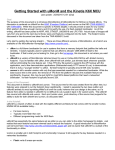
SYS68K/CPU-60
Technical Reference Manual
P/N 204077 Edition 2.3
June 1999
FORCE COMPUTERS Inc./GmbH
All Rights Reserved
This document shall not be duplicated, nor its contents used
for any purpose, unless express permission has been granted.
Copyright by FORCE COMPUTERS
World Wide Web: www.forcecomputers.com
24-hour access to on-line manuals, driver updates, and application notes
is provided via SMART, our SolutionsPLUS customer support program
that provides current technical and services information.
Headquarters
The Americas
Europe
Asia
FORCE C OMPUTERS Inc.
5799 Fontanoso Way
San Jose, CA 95138-1015
U.S.A.
FORCE COMPUTERS GmbH
Prof.-Messerschmitt-Str. 1
D-85579 Neubiberg/München
Germany
Tel.: +1 (408) 369-6000
Fax: +1 (408) 371-3382
Email support@fci.com
Tel.: +49 (89) 608 14-0
Fax: +49 (89) 609 77 93
Email support@force.de
FORCE COMPUTERS Japan KK
Miyakeya Building 4F
1-9-12 Hamamatsucho
Minato-ku, Tokyo 105
Japan
Tel.: +81 (03) 3437 3948
Fax: +81 (03) 3437 3968
Email smiyagawa@fci.com
NOTE
The information in this document has been carefully checked and is believed to be entirely reliable. FORCE COMPUTERS makes no warranty of any kind with
regard to the material in this document, and assumes no responsibility for any errors which may appear in this document. FORCE COMPUTERS reserves the right
to make changes without notice to this, or any of its products, to improve reliability, performance, or design.
FORCE COMPUTERS assumes no responsibility for the use of any circuitry other than circuitry which is part of a product of FORCE COMPUTERS Inc./GmbH.
FORCE COMPUTERS does not convey to the purchaser of the product described herein any license under the patent rights of FORCE COMPUTERS Inc./GmbH nor
the rights of others. All product names as mentioned herein are the trademarks or registered trademarks of their respective companies.
Contents
Table of Contents
Using This Manual . . . . . . . . . . . . . . . . . . . . . . . . . . . . . . . . . . . . . . . . . . . . . . . . . . . . . . . . . . ix
1
2
Introduction . . . . . . . . . . . . . . . . . . . . . . . . . . . . . . . . . . . . . . . . . . . . . . . . . . . . . . . . . . . . . . . . . 1
1.1
Specification . . . . . . . . . . . . . . . . . . . . . . . . . . . . . . . . . . . . . . . . . . . . . . . . . . . . . . . . . . . . 2
1.2
Ordering Information . . . . . . . . . . . . . . . . . . . . . . . . . . . . . . . . . . . . . . . . . . . . . . . . . . . . 6
Installation . . . . . . . . . . . . . . . . . . . . . . . . . . . . . . . . . . . . . . . . . . . . . . . . . . . . . . . . . . . . . . . . . . 7
2.1
Safety Note . . . . . . . . . . . . . . . . . . . . . . . . . . . . . . . . . . . . . . . . . . . . . . . . . . . . . . . . . . . . . 7
2.2
Installation Prerequisites and Requirements . . . . . . . . . . . . . . . . . . . . . . . . . . . . . . . . . 8
2.2.1
Requirements . . . . . . . . . . . . . . . . . . . . . . . . . . . . . . . . . . . . . . . . . . . . . . . . . . . . 8
2.2.2
Terminal Connection . . . . . . . . . . . . . . . . . . . . . . . . . . . . . . . . . . . . . . . . . . . . . . 9
2.2.3
Functional and Location Overview . . . . . . . . . . . . . . . . . . . . . . . . . . . . . . . . . . . 9
2.3
Automatic Power Up – Voltage Sensor and Watchdog Timer . . . . . . . . . . . . . . . . . . 11
2.4
Switch Settings . . . . . . . . . . . . . . . . . . . . . . . . . . . . . . . . . . . . . . . . . . . . . . . . . . . . . . . . . 11
2.5
Front Panel . . . . . . . . . . . . . . . . . . . . . . . . . . . . . . . . . . . . . . . . . . . . . . . . . . . . . . . . . . . . 15
2.6
SYS68K/CPU-60 Parameters and 16-bit Timers – CIO . . . . . . . . . . . . . . . . . . . . . . . 17
2.7
Serial I/O Ports – SCC. . . . . . . . . . . . . . . . . . . . . . . . . . . . . . . . . . . . . . . . . . . . . . . . . . . 17
2.8
SCSI. . . . . . . . . . . . . . . . . . . . . . . . . . . . . . . . . . . . . . . . . . . . . . . . . . . . . . . . . . . . . . . . . . 21
2.9
Floppy Disk – FDC . . . . . . . . . . . . . . . . . . . . . . . . . . . . . . . . . . . . . . . . . . . . . . . . . . . . . 23
2.10 Ethernet – LAN . . . . . . . . . . . . . . . . . . . . . . . . . . . . . . . . . . . . . . . . . . . . . . . . . . . . . . . . 23
2.11 VMEbus P2 Connector Pinout . . . . . . . . . . . . . . . . . . . . . . . . . . . . . . . . . . . . . . . . . . . . 24
2.12 SYS68K/IOBP-1. . . . . . . . . . . . . . . . . . . . . . . . . . . . . . . . . . . . . . . . . . . . . . . . . . . . . . . . 28
2.13 Testing the CPU Board Using VMEPROM . . . . . . . . . . . . . . . . . . . . . . . . . . . . . . . . . 30
3
Hardware . . . . . . . . . . . . . . . . . . . . . . . . . . . . . . . . . . . . . . . . . . . . . . . . . . . . . . . . . . . . . . . . . . 33
3.1
SYS68K/CPU-60 Memory Map . . . . . . . . . . . . . . . . . . . . . . . . . . . . . . . . . . . . . . . . . . . 36
3.2
SYS68K/CPU-60 Interrupt Map . . . . . . . . . . . . . . . . . . . . . . . . . . . . . . . . . . . . . . . . . . 38
SYS68K/CPU-60
Page i
Contents
3.4
3.5
3.6
SYS68K/CPU-60 Parameters and Timers – CIO Z8536 . . . . . . . . . . . . . . . . . . . . . . . 40
3.3.1
MEM-60 DRAM Capacity and CIO1 Timer 3 . . . . . . . . . . . . . . . . . . . . . . . . . 41
3.3.2
Flash VPP, Floppy Disk Control, and CIO1 Timer 2 . . . . . . . . . . . . . . . . . . . . . 42
3.3.3
MODE x Rotary Switch Setting . . . . . . . . . . . . . . . . . . . . . . . . . . . . . . . . . . . . . 43
3.3.4
On-board DRAM Capacity and Automatic A24 Expansion . . . . . . . . . . . . . . . 44
3.3.5
Board ID and DIAG Display . . . . . . . . . . . . . . . . . . . . . . . . . . . . . . . . . . . . . . . 44
3.3.6
A24-to-A32 Address Translation . . . . . . . . . . . . . . . . . . . . . . . . . . . . . . . . . . . . 45
68060 CPU . . . . . . . . . . . . . . . . . . . . . . . . . . . . . . . . . . . . . . . . . . . . . . . . . . . . . . . . . . . . 45
3.4.1
Hardware Interface of the 68060 CPU . . . . . . . . . . . . . . . . . . . . . . . . . . . . . . . . 45
3.4.2
Instruction Set of the 68060 CPU. . . . . . . . . . . . . . . . . . . . . . . . . . . . . . . . . . . . 46
3.4.3
Vector Table of the 68060 CPU . . . . . . . . . . . . . . . . . . . . . . . . . . . . . . . . . . . . . 46
Watchdog Timer . . . . . . . . . . . . . . . . . . . . . . . . . . . . . . . . . . . . . . . . . . . . . . . . . . . . . . . 48
3.5.1
Watchdog Operation. . . . . . . . . . . . . . . . . . . . . . . . . . . . . . . . . . . . . . . . . . . . . . 48
3.5.2
Watchdog Register Map. . . . . . . . . . . . . . . . . . . . . . . . . . . . . . . . . . . . . . . . . . . 49
RIALTO Bus Bridge . . . . . . . . . . . . . . . . . . . . . . . . . . . . . . . . . . . . . . . . . . . . . . . . . . . . 50
3.6.1
Register Set. . . . . . . . . . . . . . . . . . . . . . . . . . . . . . . . . . . . . . . . . . . . . . . . . . . . . 50
3.6.2
Bridge Configuration Register . . . . . . . . . . . . . . . . . . . . . . . . . . . . . . . . . . . . . . 50
3.7
FGA-002 Gate Array . . . . . . . . . . . . . . . . . . . . . . . . . . . . . . . . . . . . . . . . . . . . . . . . . . . . 51
3.8
DRAM . . . . . . . . . . . . . . . . . . . . . . . . . . . . . . . . . . . . . . . . . . . . . . . . . . . . . . . . . . . . . . . . 52
3.9
3.8.1
Register Set. . . . . . . . . . . . . . . . . . . . . . . . . . . . . . . . . . . . . . . . . . . . . . . . . . . . . 53
3.8.2
Memory Configuration Register . . . . . . . . . . . . . . . . . . . . . . . . . . . . . . . . . . . . 54
3.8.3
Memory Diagnostic Register . . . . . . . . . . . . . . . . . . . . . . . . . . . . . . . . . . . . . . . 55
3.8.4
DRAM Performance. . . . . . . . . . . . . . . . . . . . . . . . . . . . . . . . . . . . . . . . . . . . . . 56
3.8.5
Reading the DRAM Capacity. . . . . . . . . . . . . . . . . . . . . . . . . . . . . . . . . . . . . . . 57
3.8.6
DRAM Organization . . . . . . . . . . . . . . . . . . . . . . . . . . . . . . . . . . . . . . . . . . . . . 57
3.8.7
Cache Coherence and Snooping. . . . . . . . . . . . . . . . . . . . . . . . . . . . . . . . . . . . . 58
3.8.8
DRAM Access from the 68060 CPU . . . . . . . . . . . . . . . . . . . . . . . . . . . . . . . . . 59
3.8.9
DRAM Access via the VMEbus . . . . . . . . . . . . . . . . . . . . . . . . . . . . . . . . . . . . 60
3.8.10
DRAM Access from the Ethernet-Controller. . . . . . . . . . . . . . . . . . . . . . . . . . . 61
3.8.11
DRAM Access from the SCSI-Controller . . . . . . . . . . . . . . . . . . . . . . . . . . . . . 61
User SRAM (factory option) . . . . . . . . . . . . . . . . . . . . . . . . . . . . . . . . . . . . . . . . . . . . . . 61
3.9.1
Page ii
Backup Power for the User SRAM . . . . . . . . . . . . . . . . . . . . . . . . . . . . . . . . . . 62
SYS68K/CPU-60
204077 June 1999
3.3
Contents
3.10 System PROM . . . . . . . . . . . . . . . . . . . . . . . . . . . . . . . . . . . . . . . . . . . . . . . . . . . . . . . . . 62
3.10.1
Device Types for the System PROM . . . . . . . . . . . . . . . . . . . . . . . . . . . . . . . . . 63
3.10.2
Address Map of the System PROM . . . . . . . . . . . . . . . . . . . . . . . . . . . . . . . . . . 63
3.10.3
Reading and Programming the System PROM . . . . . . . . . . . . . . . . . . . . . . . . . 64
3.11 Boot PROM . . . . . . . . . . . . . . . . . . . . . . . . . . . . . . . . . . . . . . . . . . . . . . . . . . . . . . . . . . . 64
3.11.1
Boot PROM Address Map and Factory Options . . . . . . . . . . . . . . . . . . . . . . . . 66
3.11.2
Programming the Boot PROM . . . . . . . . . . . . . . . . . . . . . . . . . . . . . . . . . . . . . . 67
3.12 User Flash . . . . . . . . . . . . . . . . . . . . . . . . . . . . . . . . . . . . . . . . . . . . . . . . . . . . . . . . . . . . . 68
3.12.1
Programming the User Flash . . . . . . . . . . . . . . . . . . . . . . . . . . . . . . . . . . . . . . . 68
3.13 Local SRAM . . . . . . . . . . . . . . . . . . . . . . . . . . . . . . . . . . . . . . . . . . . . . . . . . . . . . . . . . . . 69
3.13.1
Local SRAM Organization. . . . . . . . . . . . . . . . . . . . . . . . . . . . . . . . . . . . . . . . . 69
3.13.2
Devices Types for the Local SRAM . . . . . . . . . . . . . . . . . . . . . . . . . . . . . . . . . 70
3.13.3
Backup Power for the Local SRAM. . . . . . . . . . . . . . . . . . . . . . . . . . . . . . . . . . 71
3.14 Real-Time Clock – RTC 72423 . . . . . . . . . . . . . . . . . . . . . . . . . . . . . . . . . . . . . . . . . . . . 71
3.14.1
RTC Registers Address Map . . . . . . . . . . . . . . . . . . . . . . . . . . . . . . . . . . . . . . . 72
3.14.2
Reading from or Writing to the RTC 72423 . . . . . . . . . . . . . . . . . . . . . . . . . . . 73
3.14.3
Backup Power for the RTC 72423 . . . . . . . . . . . . . . . . . . . . . . . . . . . . . . . . . . . 74
3.15 VMEbus Interface . . . . . . . . . . . . . . . . . . . . . . . . . . . . . . . . . . . . . . . . . . . . . . . . . . . . . . 75
3.15.1
Exception Signals SYSFAIL, SYSRESET, and ACFAIL . . . . . . . . . . . . . . . . . 76
3.15.2
Master Interface: Address Modifier (AM) Codes . . . . . . . . . . . . . . . . . . . . . . . 77
3.15.3
Master Interface: Data Transfer Size . . . . . . . . . . . . . . . . . . . . . . . . . . . . . . . . . 78
3.15.4
Master Interface: Burst to VMEbus . . . . . . . . . . . . . . . . . . . . . . . . . . . . . . . . . . 80
3.15.5
Slave Interface: Access Address . . . . . . . . . . . . . . . . . . . . . . . . . . . . . . . . . . . . 81
3.15.6
Slave Interface: DRAM Data Transfer Size. . . . . . . . . . . . . . . . . . . . . . . . . . . . 81
3.15.7
Slave Interface: Address Modifier Decoding and A24 Slave Mode . . . . . . . . . 81
3.15.8
Slave Interface: Locked Cycles . . . . . . . . . . . . . . . . . . . . . . . . . . . . . . . . . . . . . 82
3.16 VMEbus Arbitration . . . . . . . . . . . . . . . . . . . . . . . . . . . . . . . . . . . . . . . . . . . . . . . . . . . . 83
3.16.1
Single-Level VMEbus Arbiter . . . . . . . . . . . . . . . . . . . . . . . . . . . . . . . . . . . . . . 83
3.16.2
VMEbus Requester. . . . . . . . . . . . . . . . . . . . . . . . . . . . . . . . . . . . . . . . . . . . . . . 83
3.16.3
VMEbus Release Modes . . . . . . . . . . . . . . . . . . . . . . . . . . . . . . . . . . . . . . . . . . 84
3.16.4
VMEbus Grant Driver . . . . . . . . . . . . . . . . . . . . . . . . . . . . . . . . . . . . . . . . . . . . 86
3.17 VMEbus Slot-1 . . . . . . . . . . . . . . . . . . . . . . . . . . . . . . . . . . . . . . . . . . . . . . . . . . . . . . . . . 86
SYS68K/CPU-60
Page iii
Contents
3.17.1
Slot-1 (System Controller) Functions. . . . . . . . . . . . . . . . . . . . . . . . . . . . . . . . . 87
3.17.2
Slot-1 Detection . . . . . . . . . . . . . . . . . . . . . . . . . . . . . . . . . . . . . . . . . . . . . . . . . 87
3.17.3
Slot-1 Status Register . . . . . . . . . . . . . . . . . . . . . . . . . . . . . . . . . . . . . . . . . . . . . 88
3.17.4
The SYSCLK Driver . . . . . . . . . . . . . . . . . . . . . . . . . . . . . . . . . . . . . . . . . . . . . 88
3.17.5
VMEbus Timer. . . . . . . . . . . . . . . . . . . . . . . . . . . . . . . . . . . . . . . . . . . . . . . . . . 89
3.18 Serial I/O – SCC AM 85C30 . . . . . . . . . . . . . . . . . . . . . . . . . . . . . . . . . . . . . . . . . . . . . . 89
3.18.1
RS-485 Configuration . . . . . . . . . . . . . . . . . . . . . . . . . . . . . . . . . . . . . . . . . . . . 90
3.19 SCSI – 53C720SE. . . . . . . . . . . . . . . . . . . . . . . . . . . . . . . . . . . . . . . . . . . . . . . . . . . . . . . 92
3.19.1
SCSI Register Map. . . . . . . . . . . . . . . . . . . . . . . . . . . . . . . . . . . . . . . . . . . . . . . 93
3.19.2
Communication across the SCSI bus . . . . . . . . . . . . . . . . . . . . . . . . . . . . . . . . . 93
3.20 Floppy Disk – FDC 37C65C . . . . . . . . . . . . . . . . . . . . . . . . . . . . . . . . . . . . . . . . . . . . . . 94
3.21 Ethernet – LAN AM 79C965A . . . . . . . . . . . . . . . . . . . . . . . . . . . . . . . . . . . . . . . . . . . . 96
3.21.1
Register Access . . . . . . . . . . . . . . . . . . . . . . . . . . . . . . . . . . . . . . . . . . . . . . . . . 98
3.22 Reset Generation . . . . . . . . . . . . . . . . . . . . . . . . . . . . . . . . . . . . . . . . . . . . . . . . . . . . . . 101
3.23 Information on Front Panel Devices . . . . . . . . . . . . . . . . . . . . . . . . . . . . . . . . . . . . . . 103
4
Circuit Schematics . . . . . . . . . . . . . . . . . . . . . . . . . . . . . . . . . . . . . . . . . . . paginated separately
5
Data Sheets . . . . . . . . . . . . . . . . . . . . . . . . . . . . . . . . . . . . . . . . . . . . . . . . . paginated separately
CIO Z8536
5.2
FDC 37C65C
5.3
LAN AM 79C965A
5.4
RTC 72421
5.5
SCC AM 85C30
5.6
SCSI 53C720SE
VMEPROM . . . . . . . . . . . . . . . . . . . . . . . . . . . . . . . . . . . . . . . . . . . . . . . . . . . . . . . . . . . . . . . 125
6.1
Power-up Sequence . . . . . . . . . . . . . . . . . . . . . . . . . . . . . . . . . . . . . . . . . . . . . . . . . . . . 126
6.2
Front Panel Related VMEPROM Features. . . . . . . . . . . . . . . . . . . . . . . . . . . . . . . . . 127
6.3
Page iv
6.2.1
Reset Key . . . . . . . . . . . . . . . . . . . . . . . . . . . . . . . . . . . . . . . . . . . . . . . . . . . . . 127
6.2.2
Abort Key . . . . . . . . . . . . . . . . . . . . . . . . . . . . . . . . . . . . . . . . . . . . . . . . . . . . . 127
6.2.3
Rotary Switches . . . . . . . . . . . . . . . . . . . . . . . . . . . . . . . . . . . . . . . . . . . . . . . . 128
Memory Usage of VMEPROM. . . . . . . . . . . . . . . . . . . . . . . . . . . . . . . . . . . . . . . . . . . 132
SYS68K/CPU-60
204077 June 1999
6
5.1
Contents
6.4
6.5
6.6
7
6.3.1
Default Memory Usage of VMEPROM. . . . . . . . . . . . . . . . . . . . . . . . . . . . . . 132
6.3.2
Default ROM Use of VMEPROM . . . . . . . . . . . . . . . . . . . . . . . . . . . . . . . . . . 132
Devices and Interrupts Used by VMEPROM . . . . . . . . . . . . . . . . . . . . . . . . . . . . . . . 133
6.4.1
Addresses of the On-Board I/O Devices . . . . . . . . . . . . . . . . . . . . . . . . . . . . . 133
6.4.2
On-Board Interrupt Sources . . . . . . . . . . . . . . . . . . . . . . . . . . . . . . . . . . . . . . . 134
6.4.3
Off-Board Interrupt Sources. . . . . . . . . . . . . . . . . . . . . . . . . . . . . . . . . . . . . . . 134
6.4.4
The On-Board Real-Time Clock . . . . . . . . . . . . . . . . . . . . . . . . . . . . . . . . . . . 135
VMEPROM Commands . . . . . . . . . . . . . . . . . . . . . . . . . . . . . . . . . . . . . . . . . . . . . . . . 135
6.5.1
ARB – Set the Arbiter of the CPU Board . . . . . . . . . . . . . . . . . . . . . . . . . . . . 136
6.5.2
CONFIG – Search VMEbus for Hardware . . . . . . . . . . . . . . . . . . . . . . . . . . . 136
6.5.3
FERASE – Erase Flash Memories . . . . . . . . . . . . . . . . . . . . . . . . . . . . . . . . . . 137
6.5.4
FGA – Change Boot Setup for Gate Array . . . . . . . . . . . . . . . . . . . . . . . . . . . 138
6.5.5
FLUSH – Set Buffered Write Mode. . . . . . . . . . . . . . . . . . . . . . . . . . . . . . . . . 139
6.5.6
FMB – FORCE Message Broadcast. . . . . . . . . . . . . . . . . . . . . . . . . . . . . . . . . 140
6.5.7
FPROG – Program Flash Memories . . . . . . . . . . . . . . . . . . . . . . . . . . . . . . . . 141
6.5.8
FUNCTIONAL – Perform Functional Test . . . . . . . . . . . . . . . . . . . . . . . . . . . 142
6.5.9
INFO – Information about the CPU Board . . . . . . . . . . . . . . . . . . . . . . . . . . . 143
6.5.10
MEM – Set Data Bus Width of the VMEbus . . . . . . . . . . . . . . . . . . . . . . . . . . 143
6.5.11
RUNINRAM – Run VMEPROM in RAM . . . . . . . . . . . . . . . . . . . . . . . . . . . 144
6.5.12
RUNINROM – Run VMEPROM in ROM . . . . . . . . . . . . . . . . . . . . . . . . . . . 145
6.5.13
SELFTEST – Perform On-Board Selftest . . . . . . . . . . . . . . . . . . . . . . . . . . . . 145
Installing a New Hard Disk (Using FRMT and INIT). . . . . . . . . . . . . . . . . . . . . . . . . 146
Appendix to VMEPROM . . . . . . . . . . . . . . . . . . . . . . . . . . . . . . . . . . . . . . . . . . . . . . . . . . . . 151
7.1
Driver Installation . . . . . . . . . . . . . . . . . . . . . . . . . . . . . . . . . . . . . . . . . . . . . . . . . . . . . 151
7.1.1
VMEbus Memory. . . . . . . . . . . . . . . . . . . . . . . . . . . . . . . . . . . . . . . . . . . . . . . 151
7.1.2
SYS68K/SIO-1/2 . . . . . . . . . . . . . . . . . . . . . . . . . . . . . . . . . . . . . . . . . . . . . . . 152
7.1.3
SYS68K/ISIO-1/2 . . . . . . . . . . . . . . . . . . . . . . . . . . . . . . . . . . . . . . . . . . . . . . 153
7.1.4
SYS68K/WFC-1 Disk Controller. . . . . . . . . . . . . . . . . . . . . . . . . . . . . . . . . . . 155
7.1.5
SYS68K/ISCSI-1 Disk Controller . . . . . . . . . . . . . . . . . . . . . . . . . . . . . . . . . . 156
7.1.6
Local SCSI Controller . . . . . . . . . . . . . . . . . . . . . . . . . . . . . . . . . . . . . . . . . . . 157
7.2
S-Record Formats . . . . . . . . . . . . . . . . . . . . . . . . . . . . . . . . . . . . . . . . . . . . . . . . . . . . . 158
7.3
System RAM Definitions . . . . . . . . . . . . . . . . . . . . . . . . . . . . . . . . . . . . . . . . . . . . . . . . 159
SYS68K/CPU-60
Page v
Contents
Task Control Block Definitions . . . . . . . . . . . . . . . . . . . . . . . . . . . . . . . . . . . . . . . . . . 162
7.5
Interrupt Vector Table of VMEPROM . . . . . . . . . . . . . . . . . . . . . . . . . . . . . . . . . . . . 165
7.6
Benchmark Source Code. . . . . . . . . . . . . . . . . . . . . . . . . . . . . . . . . . . . . . . . . . . . . . . . 168
7.7
Modifying Special Locations in ROM . . . . . . . . . . . . . . . . . . . . . . . . . . . . . . . . . . . . . 174
7.8
Binding Applications to VMEPROM . . . . . . . . . . . . . . . . . . . . . . . . . . . . . . . . . . . . . 177
7.8.1
Using External Memory . . . . . . . . . . . . . . . . . . . . . . . . . . . . . . . . . . . . . . . . . . 177
7.8.2
Using System Flash Memory . . . . . . . . . . . . . . . . . . . . . . . . . . . . . . . . . . . . . . 177
FGA Boot . . . . . . . . . . . . . . . . . . . . . . . . . . . . . . . . . . . . . . . . . . . . . . . . . . . . . . . . . . . . . . . . . 179
8.1
Boot Sequence . . . . . . . . . . . . . . . . . . . . . . . . . . . . . . . . . . . . . . . . . . . . . . . . . . . . . . . . 179
8.2
Debugger Commands . . . . . . . . . . . . . . . . . . . . . . . . . . . . . . . . . . . . . . . . . . . . . . . . . . 182
8.3
Page vi
8.2.1
AS – Line Assembler . . . . . . . . . . . . . . . . . . . . . . . . . . . . . . . . . . . . . . . . . . . . 182
8.2.2
BANNER – Display Banner Again . . . . . . . . . . . . . . . . . . . . . . . . . . . . . . . . . 184
8.2.3
CONT – Continue with Calling Routine . . . . . . . . . . . . . . . . . . . . . . . . . . . . . 184
8.2.4
DI – Disassembler . . . . . . . . . . . . . . . . . . . . . . . . . . . . . . . . . . . . . . . . . . . . . . 184
8.2.5
DRAMINIT – Initialize DRAM. . . . . . . . . . . . . . . . . . . . . . . . . . . . . . . . . . . . 185
8.2.6
FERASE – Erase Flash Memories . . . . . . . . . . . . . . . . . . . . . . . . . . . . . . . . . . 185
8.2.7
FPROG – Program Flash Memories . . . . . . . . . . . . . . . . . . . . . . . . . . . . . . . . 186
8.2.8
GO – Go to Subroutine. . . . . . . . . . . . . . . . . . . . . . . . . . . . . . . . . . . . . . . . . . . 188
8.2.9
LO – Load S-Records to Memory . . . . . . . . . . . . . . . . . . . . . . . . . . . . . . . . . . 188
8.2.10
NETLOAD – Load File via Network to Memory . . . . . . . . . . . . . . . . . . . . . . 190
8.2.11
NETSAVE – Save Data via Network to File . . . . . . . . . . . . . . . . . . . . . . . . . . 191
8.2.12
SETUP – Change Initialization Values . . . . . . . . . . . . . . . . . . . . . . . . . . . . . . 193
8.2.13
SLOT – Change Slot Number and VMEbus Slave Address . . . . . . . . . . . . . . 194
8.2.14
VMEADDR – Change VMEbus Slave Address . . . . . . . . . . . . . . . . . . . . . . . 195
FGA Boot Utility Functions . . . . . . . . . . . . . . . . . . . . . . . . . . . . . . . . . . . . . . . . . . . . . 196
8.3.1
Extended Flash Memory Programming . . . . . . . . . . . . . . . . . . . . . . . . . . . . . . 197
8.3.2
Erase Flash Memories . . . . . . . . . . . . . . . . . . . . . . . . . . . . . . . . . . . . . . . . . . . 198
8.3.3
Get System Values in SRAM . . . . . . . . . . . . . . . . . . . . . . . . . . . . . . . . . . . . . . 199
8.3.4
Get Application Values in SRAM . . . . . . . . . . . . . . . . . . . . . . . . . . . . . . . . . . 200
8.3.5
Get Ethernet Number . . . . . . . . . . . . . . . . . . . . . . . . . . . . . . . . . . . . . . . . . . . . 200
8.3.6
Get Memory Limits . . . . . . . . . . . . . . . . . . . . . . . . . . . . . . . . . . . . . . . . . . . . . 201
SYS68K/CPU-60
204077 June 1999
8
7.4
Tables and Figures
List of Tables and Figures
Page
Referenced manuals separately available from FORCE COMPUTERS . . . . . . . . . x
History of manual publication . . . . . . . . . . . . . . . . . . . . . . . . . . . . . . . . . . . . . . . . . xi
Fonts, Notations and Conventions . . . . . . . . . . . . . . . . . . . . . . . . . . . . . . . . . . . . . . xi
Specification for the SYS68K/CPU-60 board . . . . . . . . . . . . . . . . . . . . . . . . . . . . . 2
Ordering information for the SYS68K/CPU-60. . . . . . . . . . . . . . . . . . . . . . . . . . . . 6
Block diagram of the SYS68K/CPU-60. . . . . . . . . . . . . . . . . . . . . . . . . . . . . . . . . . 9
Location diagram of the SYS68K/CPU-60 (schematic) . . . . . . . . . . . . . . . . . . . . 10
Switch settings . . . . . . . . . . . . . . . . . . . . . . . . . . . . . . . . . . . . . . . . . . . . . . . . . . . . 11
Front panel features . . . . . . . . . . . . . . . . . . . . . . . . . . . . . . . . . . . . . . . . . . . . . . . . 15
Pinout of the front panel serial I/O ports config. for RS-232 . . . . . . . . . . . . . . . . . 19
Pinout of the front panel serial I/O ports config. for RS-422 . . . . . . . . . . . . . . . . . 19
Pinout of the front panel serial I/O ports config. for RS-485 . . . . . . . . . . . . . . . . . 20
15-pin AUI-Ethernet connector . . . . . . . . . . . . . . . . . . . . . . . . . . . . . . . . . . . . . . . 24
P2 connector pinout with serial I/O config. for RS-232. . . . . . . . . . . . . . . . . . . . . 25
P2 connector pinout with serial I/O config. for RS-422. . . . . . . . . . . . . . . . . . . . . 26
P2 connector pinout with serial I/O config. for RS-485. . . . . . . . . . . . . . . . . . . . . 27
SYS68K/IOBP-1 pin assignment for VME P2 . . . . . . . . . . . . . . . . . . . . . . . . . . . 28
POST codes indicating boot status . . . . . . . . . . . . . . . . . . . . . . . . . . . . . . . . . . . . . 30
SYS68K/CPU-60 block diagram . . . . . . . . . . . . . . . . . . . . . . . . . . . . . . . . . . . . . . 35
SYS68K/CPU-60 memory map . . . . . . . . . . . . . . . . . . . . . . . . . . . . . . . . . . . . . . . 37
SYS68K/CPU-60 interrupt map . . . . . . . . . . . . . . . . . . . . . . . . . . . . . . . . . . . . . . . 39
SYS68K/CPU-60 parameters and timers register map and CIO loc.. . . . . . . . . . . 41
CIO1 port C data register . . . . . . . . . . . . . . . . . . . . . . . . . . . . . . . . . . . . . . . . . . . . 41
CIO1 port B data register . . . . . . . . . . . . . . . . . . . . . . . . . . . . . . . . . . . . . . . . . . . . 42
CIO1 port A data register (including MODE x status register) . . . . . . . . . . . . . . . 43
CIO2 port C data register . . . . . . . . . . . . . . . . . . . . . . . . . . . . . . . . . . . . . . . . . . . . 44
CIO2 port B data register . . . . . . . . . . . . . . . . . . . . . . . . . . . . . . . . . . . . . . . . . . . . 44
Naming the parts of the front-panel hexadecimal display . . . . . . . . . . . . . . . . . . . 45
CIO2 port A data register . . . . . . . . . . . . . . . . . . . . . . . . . . . . . . . . . . . . . . . . . . . . 45
68060 CPU exception vector assignments . . . . . . . . . . . . . . . . . . . . . . . . . . . . . . . 46
Watchdog register map (superset of the memory controller register map) . . . . . . 49
Watchdog retrigger register (WDR). . . . . . . . . . . . . . . . . . . . . . . . . . . . . . . . . . . . 49
RIALTO bus bridge register map. . . . . . . . . . . . . . . . . . . . . . . . . . . . . . . . . . . . . . 50
Bridge configuration register (BCR) . . . . . . . . . . . . . . . . . . . . . . . . . . . . . . . . . . . 50
Snoop window definition in BCR . . . . . . . . . . . . . . . . . . . . . . . . . . . . . . . . . . . . . 51
Memory controller register map (included in the watchdog register map) . . . . . . 53
MCR, memory configuration register . . . . . . . . . . . . . . . . . . . . . . . . . . . . . . . . . . 54
Memory diagnostic register (MDR) . . . . . . . . . . . . . . . . . . . . . . . . . . . . . . . . . . . . 55
DRAM capacity encoding at CIOx port C data registers . . . . . . . . . . . . . . . . . . . . 57
SYS68K/CPU-60
Tab./Fig.
Tab.
Tab.
Tab.
Tab.
Tab.
Fig.
Fig.
Tab.
Tab.
Tab.
Tab.
Tab.
Tab.
Fig.
Fig.
Fig.
Fig.
Tab.
Fig.
Tab.
Tab.
Tab.
Tab.
Tab.
Tab.
Tab.
Tab.
Fig.
Tab.
Tab.
Tab.
Tab.
Tab.
Tab.
Tab.
Tab.
Tab.
Tab.
Tab.
1
2
3
1
2
1
2
3
4
5
6
7
8
3
4
5
6
9
7
10
11
12
13
14
15
16
17
8
18
19
20
21
22
23
24
25
26
27
28
Page vii
Tables and Figures
Page
Tab./Fig.
Tab.
Tab.
Tab.
Tab.
Tab.
Tab.
Tab.
Tab.
Tab.
Tab.
Tab.
Tab.
Tab.
Tab.
Tab.
Tab.
Tab.
Tab.
Tab.
Tab.
Tab.
Tab.
Tab.
Tab.
Tab.
Tab.
Fig.
Tab.
Tab.
Tab.
Tab.
Tab.
Tab.
Tab.
Tab.
Tab.
Tab.
Tab.
Tab.
Tab.
Tab.
Tab.
Tab.
Fig.
Fig.
Tab.
29
30
31
32
33
34
35
36
37
38
39
40
41
42
43
44
45
46
47
48
49
50
51
52
53
54
9
55
56
57
58
59
60
61
62
63
64
65
66
67
68
69
70
10
10
71
204077 June 1999
DRAM device types and number of used banks . . . . . . . . . . . . . . . . . . . . . . . . . . 58
Default DRAM access address ranges from the 68060 CPU . . . . . . . . . . . . . . . . . 59
User SRAM features. . . . . . . . . . . . . . . . . . . . . . . . . . . . . . . . . . . . . . . . . . . . . . . . 61
System PROM features . . . . . . . . . . . . . . . . . . . . . . . . . . . . . . . . . . . . . . . . . . . . . 62
System PROM device types . . . . . . . . . . . . . . . . . . . . . . . . . . . . . . . . . . . . . . . . . . 63
System PROM address map . . . . . . . . . . . . . . . . . . . . . . . . . . . . . . . . . . . . . . . . . . 63
Boot PROM features . . . . . . . . . . . . . . . . . . . . . . . . . . . . . . . . . . . . . . . . . . . . . . . 65
Boot PROM address map, factory options, and device types . . . . . . . . . . . . . . . . 66
User flash factory options and device types . . . . . . . . . . . . . . . . . . . . . . . . . . . . . . 68
Local SRAM features . . . . . . . . . . . . . . . . . . . . . . . . . . . . . . . . . . . . . . . . . . . . . . . 69
Local SRAM factory options and device types . . . . . . . . . . . . . . . . . . . . . . . . . . . 70
RTC 72423 features . . . . . . . . . . . . . . . . . . . . . . . . . . . . . . . . . . . . . . . . . . . . . . . . 71
RTC registers address map. . . . . . . . . . . . . . . . . . . . . . . . . . . . . . . . . . . . . . . . . . . 72
Address modifier (AM) ranges A32/A24/A16. . . . . . . . . . . . . . . . . . . . . . . . . . . . 77
Address ranges related to AM codes . . . . . . . . . . . . . . . . . . . . . . . . . . . . . . . . . . . 77
Bus widths related to address ranges: VMEbus master interface. . . . . . . . . . . . . . 78
VMEbus master transfer cycles defined for D32 data bus width. . . . . . . . . . . . . . 79
VMEbus master transfer cycles defined for D16 data bus width. . . . . . . . . . . . . . 79
VMEbus slave AM codes. . . . . . . . . . . . . . . . . . . . . . . . . . . . . . . . . . . . . . . . . . . . 82
Valid configurations for VMEbus release modes . . . . . . . . . . . . . . . . . . . . . . . . . 84
Slot-1 status register (RO) . . . . . . . . . . . . . . . . . . . . . . . . . . . . . . . . . . . . . . . . . . . 88
Serial I/O channel register map and hybrid locations . . . . . . . . . . . . . . . . . . . . . . 90
Bit 7 of the WR5 register . . . . . . . . . . . . . . . . . . . . . . . . . . . . . . . . . . . . . . . . . . . . 90
SCSI-53C720SE GPCNTL register . . . . . . . . . . . . . . . . . . . . . . . . . . . . . . . . . . . . 91
SCSI-53C720SE GPREG register . . . . . . . . . . . . . . . . . . . . . . . . . . . . . . . . . . . . . 91
FDC register map . . . . . . . . . . . . . . . . . . . . . . . . . . . . . . . . . . . . . . . . . . . . . . . . . . 95
Block diagram of the Ethernet interface. . . . . . . . . . . . . . . . . . . . . . . . . . . . . . . . . 96
Initializing the LAN AM 79C965A register access . . . . . . . . . . . . . . . . . . . . . . . . 98
Ethernet controller address layout (16-Bit mode) . . . . . . . . . . . . . . . . . . . . . . . . . 99
Example word-swapped init. block for LAN AM 79C965A in 16-bit mode. . . . 100
Initializing a receive descriptor in 16-bit mode . . . . . . . . . . . . . . . . . . . . . . . . . . 100
Examples for power-up and reset configuration by rotary switches . . . . . . . . . . 129
Power-up and reset actions defined by rotary switch MODE 2 . . . . . . . . . . . . . . 130
Power-up and reset actions defined by rotary switch MODE 1 . . . . . . . . . . . . . . 131
Main memory layout . . . . . . . . . . . . . . . . . . . . . . . . . . . . . . . . . . . . . . . . . . . . . . 132
Layout of system flash memory . . . . . . . . . . . . . . . . . . . . . . . . . . . . . . . . . . . . . . 133
On-board I/O devices . . . . . . . . . . . . . . . . . . . . . . . . . . . . . . . . . . . . . . . . . . . . . . 133
On-board interrupt sources . . . . . . . . . . . . . . . . . . . . . . . . . . . . . . . . . . . . . . . . . . 134
Off-board interrupt sources . . . . . . . . . . . . . . . . . . . . . . . . . . . . . . . . . . . . . . . . . 135
Base addresses of SIO-1/2 ports. . . . . . . . . . . . . . . . . . . . . . . . . . . . . . . . . . . . . . 153
Base addresses of ISIO-1/2 ports . . . . . . . . . . . . . . . . . . . . . . . . . . . . . . . . . . . . . 154
Types of S-record format modules and VMEPROM support . . . . . . . . . . . . . . . 158
User patch table . . . . . . . . . . . . . . . . . . . . . . . . . . . . . . . . . . . . . . . . . . . . . . . . . . 175
Boot up procedure . . . . . . . . . . . . . . . . . . . . . . . . . . . . . . . . . . . . . . . . . . . . . . . . 180
Boot up procedure (continued). . . . . . . . . . . . . . . . . . . . . . . . . . . . . . . . . . . . . . . 181
Stack frame. . . . . . . . . . . . . . . . . . . . . . . . . . . . . . . . . . . . . . . . . . . . . . . . . . . . . . 196
Page viii
SYS68K/CPU-60
Using This Manual
Using This Manual
This section does not provide information on the product but on common
features of the manual itself:
• its structure,
• special layout conventions,
• and related documents.
Audience of the Manual
This Technical Reference Manual is intended for hard- and software developers installing and integrating the SYS68K/CPU-60 into their systems.
Overview of the Manual
This Technical Reference Manual provides a comprehensive hardware
and software guide to your board.
IMPORTANT
i
Please take a moment to examine the “Table of Contents” to see how this
documentation is structured. This will be of value to you when looking
for information in the future.
It includes
• a brief overview of the product, the specifications, the ordering information: see section 1 “Introduction” on page 1.
• the installation instructions for powering up the board: see section 2
“Installation” on page 7. It includes the default configuration (switches
and the like), initialization, and connector pinouts.
The installation instructions also appear as the product’s installation
guide – a separate manual delivered together with each product
shipped.
• a detailed hardware description: see section 3 “Hardware” on page 33.
• the circuit schematics of the board for reference purposes.
The circuit schematics are packaged separately to enable easy updating. They will always be shipped together with this manual. Therefore:
☞
SYS68K/CPU-60
Insert the circuit schematics now: see section 4 “Circuit
Schematics”.
Page ix
Using This Manual
• the data sheets of board components that are relevant for configuring
and integrating the board in systems. The following data sheets are
delivered:
– Motorola 68060 (delivered as a separate manual)
– CIO Z8536
– FDC 37C65C: pin-to-pin compatible with industry standard
WD37C65C
– LAN AM 79C965A
– RTC 72421
– SCC AM 85C30
– SCSI 53C720SE
The data sheets are packaged separately to enable easy updating. They
are always shipped together with this manual. Therefore:
☞
Insert the data sheets now: see section 5 “Data Sheets”.
• a detailed description of VMEPROM and FGA Boot which control the
CPU board operations: see section 6 “VMEPROM” on page 125,
section 7 “Appendix to VMEPROM” on page 151, and section 8 “FGA
Boot” on page 179.
There is additional space allocated in the manual for user notes, modifications, etc.
Referenced Manuals
Referenced manuals separately available from FORCE COMPUTERS
Referenced manual
Pages referring to the manual
IOPI-2 User’s Installation
24
SIO User's Manual
152
204077 June 1999
Table 1
Page x
SYS68K/CPU-60
Using This Manual
Publication History of the Manual
Table 2
History of manual publication
Edition
Date
Description
1
July 1996
First print
2
August 1996
Editorial Changes
2.1
July 1997
Extended NETLOAD and NETSAVE
FGA Boot debugger commands.
Corrected FDC register map, corrected pinout of front-panel serial I/O
port, and corrected units for VMEBUSTIMER bits (memory configuration register).
2.2
January 1999
Switch settings for RS-485 corrected, RS-485 configuration described
Fonts, Notations and Conventions
Table 3
Fonts, Notations and Conventions
SYS68K/CPU-60
Notation
Description
0000.000016
Typical notation for hexadecimal numbers (digits are
0 through F), e.g. used for addresses and offsets.
Note the dot marking the 4th (to its right) and 5th (to
its left) digit.
00008
Same for octal numbers (digits are 0 through 7)
00002
Same for binary numbers (digits are 0 and 1)
Program
Typical character format used for names, values, and
the like that should be used typing literally the same
word. Also used for on-screen-output.
Variable
Typical character format for words that represent a
part of a command, a programming statement, or the
like and that will be replaced by an applicable value
when actually applied.
Page xi
Using This Manual
Icons for Ease of Use: Safety Notes and Tips & Tricks
There are 3 levels of safety notes used in this manual which are described
below in brief by displaying a typical layout example.
Be sure to always read and follow the safety notes of a section first –
before acting as documented in the other parts of the section.
CAUTION
Dangerous situation: injuries of people and severe damage to objects possible.
NOTICE
Possibly dangerous situation: no injuries to people but damage to objects
possible.
!
IMPORTANT
204077 June 1999
i
No danger encountered. Only application hints and time-saving tips &
tricks or information on typical errors when using the information mentioned below this safety hint.
Page xii
SYS68K/CPU-60
Introduction
1
Introduction
The SYS68K/CPU-60 is a high performance single-board computer providing an A32/D32 VMEbus interface including DMA. It is based on
• the 68060 CPU,
• the FORCE gate array FGA-002,
• and the VMEbus.
Memory
The SYS68K/CPU-60 provides up to 32 Mbyte DRAM on-board (field
upgradable). Up to 128 Mbyte DRAM are available with the
SYS68K/MEM-60 extension module. Up to 2 Mbyte user SRAM, up to
512 Kbyte local SRAM with battery backup, up to 8 Mbyte system
PROM, and up to 1 Mbyte boot PROM are available.
The shared DRAM is accessible from the 68060 CPU, the FGA-002 onchip DMA controller, the SCSI on-chip DMA controller, the LAN onchip DMA controller, and also from VMEbus masters.
Interfaces
The SYS68K/CPU-60 incorporates SCSI-2, Ethernet, and serial I/O onboard to provide full single-board computer functionality.
The SYS68K/CPU-60 has 2 serial ports at the front panel permitting a
console port for download and data communication. Both ports use standard 9-pin D-Sub connectors.
CPU speed
The 68060 CPU runs at 50 MHz and has cache snooping support for alternate master access to the shared DRAM.
Real-time clock
A real-time clock with battery backup is also available.
SYS68K/CPU-60
Page 1
Specification
1.1
Introduction
Specification
Table 1
Specification for the SYS68K/CPU-60 board
CPU type
68060
With snooping support (write through for shared data
necessary)
CPU clock frequency
50 MHz
CPU bus frequency (half of CPU clock frequency)
25 MHz
DRAM
CPU-60D/4
CPU-60D/8
CPU-60D/16
CPU-60D/32
4 Mbyte on-board
8 Mbyte on-board
(Upgradable with MEM-60/8
to 16 Mbyte in total)
16 Mbyte on-board
(Upgradable with MEM-60/16
to 32 Mbyte in total)
32 Mbyte on-board
32-bit wide, byte parity, accessible from the CPU,
FGA-002, SCSI and Ethernet on-chip DMA controller,
and also from other VMEbus masters, up to 128-Mbyte
DRAM with memory extension module
System PROM
Flash memory, 32-bit wide memory data path, reprogrammable on-board, hardware write protection (independent from boot PROM)
User SRAM
0 Mbyte (factory option)
4 Mbyte
8 Mbyte (factory option)
2 Mbyte (factory option)
32-bit wide, with on-board battery and +5VSTDBY
line backup, accessible from the CPU, SCSI and Ethernet on-chip DMA controller, and also from other
VMEbus masters
Boot PROM
Factory options:
256 Kbyte (12V flash mem.)
512 Kbyte (12V flash mem.)
1 Mbyte (5V flash mem.)
1 Mbyte (OTP)
(more configurations possible)
204077 June 1999
12V flash memory, 8-bit wide, reprogrammable onboard in case of flash memory, hardware write protection in case of flash memory (independent from system
PROM), 32-pin PLCC sockets
128 Kbyte (12V flash mem.)
Page 2
SYS68K/CPU-60
Introduction
Specification
Table 1
Specification for the SYS68K/CPU-60 board (cont.)
Local SRAM
32 Kbyte (factory option)
128 Kbyte
512 Kbyte (factory option)
8-bit wide, with on-board battery and +5VSTDBY line
backup
User flash
128 Kbyte (factory option)
256 Kbyte
512 Kbyte (factory option)
8-bit wide, reprogrammable on-board, hardware write
protectable
Serial I/O interfaces
SCC 85C30
available via the front panel (permitting a console port,
download, and data communication)
2
available via the 3-row VME P2 connector
1 (2 as factory option, the second port is not available with
16-bit wide SCSI option)
RS-232, RS-422, or RS-485 compatible via FORCE
hybrids FH-00x, SDLC, HDLC, IBM BISYNC, and
ASYNC protocol support, up to 38.4 Kbit/s asynchronous data rate
Ethernet interface on front panel
Via AM 79C965
AUI via 15-pin D-Sub
Cheapernet via SMB (factory
option)
SCSI interface, single-ended
Via NCR 53C720SE
8-bit (fast)
16-bit (wide; factory option,
the wide SCSI option is not
available with 2 serial ports on
the P2 connector)
SCSI-2, 68040 compatible DMA controller with burst
capability, SCSI active termination, SCSI port available on VMEbus P2 connector
Floppy disk interface
FDC 37C65C
FDC37C65C is pin-to-pin compatible with industry
standard WD37C65C
SYS68K/CPU-60 parameters controllable
Via CIO Z8536
Timers
Via 2 CIO Z8536
Six 16-bit timers
With 500 ns resolution
Watchdog timer
Reset/NMI
Real-time clock
Via RTC 72423
With on-board battery and +5VSTDBY line backup;
IRQ capability
SYS68K/CPU-60
Page 3
Specification
Introduction
Table 1
Specification for the SYS68K/CPU-60 board (cont.)
VMEbus interface
Master
Via FGA-002
A32, A24, A16: D8, D16, D32,
UAT, RMW
Master AM CODES:
Standard supervisory data/program access
Standard non-privileged data/program access
Short supervisory access
Short non-privileged access
Extended supervisory data/program access
Extended non-privileged data/program access
Slave
A32, A24: D8, D16, D32,
UAT, RMW
Software programmable (FGA-002, A24 logic) access address
Slave AM CODES:
Standard supervisory data/program access
Standard non-privileged data/program access
Extended supervisory data/program access
Extended non-privileged data/program access
Arbiter
Arbiter request modes
SYSCLK driver
IACK daisy chain driver
Slot 1 function switch
Mailbox interrupts
Single-level with arbitration
timeout
ROR, RBCLR, REC, RAT
yes
yes
yes
8
FORCE Message Broadcast
FMB-FIFO 0
FMB-FIFO 1
8 Byte
1 Byte
Interrupts
VMEbus and local interrupt handler
Programmable IRQ levels for all sources
Total number of IRQ sources
1 to 7
yes
42
Reset and abort switches
yes
512 Kbyte
204077 June 1999
VMEPROM firmware installed on all board versions
Page 4
SYS68K/CPU-60
Introduction
Specification
Table 1
Specification for the SYS68K/CPU-60 board (cont.)
Power requirements (for a SYS68K/CPU-60D/32)
+ 5 V max
+12 V max
3.5 A typical
0.1 A typical – with no
Ethernet MAU
plugged
0.1 A typical
- 12 V max
Backup battery at location BAT 1
CR2032-type lithium battery
Front panel features
Reset and abort key
4 Status LEDs
7-segment display
2 rotary switches
Operating temperature with forced air cooling
Storage temperature
Without battery
With installed battery
Relative humidity (non-condensing)
-40 °C to +85 °C
-40 °C to +60 °C
5 % to 95 %
Board dimensions
160 mm x 233 mm
No. of slots used
1
Standards compliance
VMEbus interface
ANSI/VITA 1-1994
SYS68K/CPU-60
0 °C to +55 °C
Page 5
Ordering Information
1.2
Introduction
Ordering Information
Table 2
Ordering information for the SYS68K/CPU-60
Product name
Product description
SYS68K/CPU-60D/4,
…/8, …/16, …/32
50 MHz 68060 based CPU board (“60D” in product
name, with “60E” it is based on a 66 MHz 68060), 32-bit
DMA, 4 (8/16/32) Mbyte shared memory, 2 serial I/O
channels (RS-232), SCSI, floppy disk and Ethernet interface, VMEPROM documentation not included.
SYS68K/CPU-60D/8 field upgradable to a total of 16
Mbyte shared memory by installing the MEM-60/8 memory module (SYS68K/CPU-60x/16 field upgradable to a
total of 32 Mbyte by MEM-60/16).
MEM-60/8, …/16
SYS68K/CPU-60Lite/4
50 MHz 68LC060 based CPU board, 32-bit DMA, 4
(8/16/32) Mbyte shared memory, 2 serial I/O channels
(RS-232), VMEPROM documentation not included.
UM SYS68K/CPU-60
SYS68K/CPU-60 Technical Reference Manual Set including VMEPROM and FGA-002 manuals.
UM SYS68K/FGA-002
FORCE Gate Array (FGA-002) User's Manual
UM SYS68K/VMEPROM/32
VMEPROM User's Manual for 32-bit CPUs
SYS68K/IOBP-1
Rear I/O paddel panel for single board computers providing connectors for 8-bit SCSI, floppy disk drive and one
serial I/O port.
IOPI-2
Rear I/O paddel panel for single board computers providing connectors for 8-bit SCSI, floppy disk drive and one
serial I/O port.
SYS68K/CABLE 9-25 SET
Set of 4 adapter cables 9-pin D-Sub male connector to
25-pin D-Sub female connector, length 2 m
(SYS68K/CPU-60)
Hybrids for the serial I/O interfaces
(10 hybrids per set):
RS-232 protocol
SYS68K/FH003/SET
RS-422 protocol
SYS68K/FH007/SET
RS-485 protocol
204077 June 1999
SYS68K/FH002/SET
Page 6
SYS68K/CPU-60
Installation
Safety Note
2
Installation
2.1
Safety Note
To ensure proper functioning of the product during its usual lifetime, take
the following precautions before handling the board.
CAUTION
Malfunction or damage to the board or connected components
Electrostatic discharge and incorrect board installation and uninstallation
can damage circuits or shorten their lifetime.
• Before installing or uninstalling the board, read this Installation section.
• Before installing or uninstalling MEM-60 memory modules, read the
MEM-60 Installation Guide packaged together with the modules.
• Before installing or uninstalling the board, in a VME rack turn off the
power.
• Before touching integrated circuits, ensure that you are working in an
electrostatic free environment.
• Ensure that the board is connected to the VMEbus via both the P1 and
the P2 connectors and that power is available on both of them.
• When operating the board in areas of strong electromagnetic radiation,
ensure that the board
– is bolted on the VME rack
– and shielded by closed housing.
CAUTION
Damage of components caused by inappropriate floppy drive installation
There are floppy disk drives that provide means to connect the floppy
disk drive frame electrically with DC ground, e.g., by inserting a jumper
on the floppy disk drive.
• Before installing a floppy disk drive, always make sure that the floppy
disk drive’s frame is not electrically connected with DC ground.
NOTICE
!
Damaging SYS68K/CPU-60 components
On the backplane the jumper for IACKIN-IACKOUT-bypass must be removed for proper operation. This is not necessary on active backplanes.
SYS68K/CPU-60
Page 7
Installation Prerequisites and Requirements
CAUTION
Installation
Maintenance of the CPU board:
The board is designed to be maintenance-free. However, note that a Lithium battery is installed on the board. The battery provides a data retention
of 7 years summing up all periods of actual battery use. Therefore,
FORCE COMPUTERS assumes that there usually is no need to exchange
the Lithium battery except for example in the case of long-term spare part
handling. Observe the following safety notes:
• Incorrect exchange of Lithium batteries can result in a hazardous
explosion.
• Exchange the battery before 7 years of actual battery use have elapsed.
• Exchanging the battery always results in data loss of the devices which
use the battery as power backup. Therefore, back up affected data
before exchanging the battery.
• Always use the same type of Lithium battery as is already installed.
• When installing the new battery ensure that the marked dot on top of
the battery covers the dot marked on the chip.
• Used batteries have to be disposed according to your country’s legislation.
2.2
Installation Prerequisites and Requirements
IMPORTANT
i
2.2.1
Before powering up
• check this section for installation prerequisites and requirements
• and check the consistency of the current switch settings (see
section 2.4 “Switch Settings” on page 11).
Requirements
The installation requires only
• a power supply
• and a VMEbus backplane with P1 and P2 connector.
Power supply
The power supply must meet the following specifications:
• required for the processor board: +5 V (3.5 A typical for a
SYS68K/CPU-60D/32, 3.0 A typical for a SYS68K/CPU-60D/4)
– +12 V (0.1 A typical – with no Ethernet MAU plugged)
– and –12 V (0.1 A typical)
Page 8
SYS68K/CPU-60
204077 2 – 3 June 1999
• required for the RS-232 serial interface and the Ethernet interface:
Installation
2.2.2
Installation Prerequisites and Requirements
Terminal Connection
For the initial power-up, a terminal can be connected to the standard
9-pin D-Sub connector of serial port 1, which is located at the front panel
(see section 2.7 “Serial I/O Ports – SCC” on page 17).
2.2.3
Functional and Location Overview
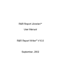
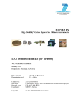
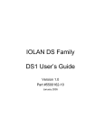
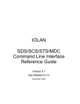
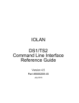
Figure 1 gives a functional overview, figure 2 highlights the locations of
the important SYS68K/CPU-60 components.
Figure 1
Block diagram of the SYS68K/CPU-60
68060
CPU
F
r
o
n
t
p
a
n
e
l
DRAM
on-board
MEM-60
RIALTO
bus bridge
(060/020)
Memory
Memory control
bus
System
PROM
FLXI bus
(020 bus)
I/O bus
CPU bus
(060 bus)
User
SRAM
RTC
Local SRAM
(NVRAM)
Ethernet
LAN
VESA local
bus (VL bus)
SCSI
(+ SCSIbus
Termin.)
AUX DMA
FDC
CIO
VL
adaption
FGA-002
Boot
PROM
User flash
(local flash)
V
M
E
b
us
SCC
4 LEDs
Hex. Displ.
2 rotary sw.
Reset key
Abort key
Serial I/O
1 and 2
SCSIbus
SYS68K/CPU-60
Page 9
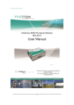
Installation Prerequisites and Requirements
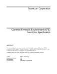
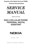
Figure 2
Installation
Location diagram of the SYS68K/CPU-60 (schematic)
Front panel
10Base2
1
AUI
(option)
ETHERNET
SERIAL
2 SYSF
UL
1
RUN
BM
4 LEDs
A
B
O
R
T
2
MODE
DIAG
2 rotary
switches
Status
display
R
E
S
E
T
Top
Ser. I/O 1
J21
Ser. I/O 2
J22
MEM-60 connector
Ethernet
DRAM Bank 2
(8 of 9)
SW12
68060
CPU
Memory control
Watchdog timer
CIO
1
RIALTO
bus
bridge
SCSI
SCC
System PROM
CIO
2
FGA-002
NVRAM
User flash
J31
FDC
Backup
battery
#1
J 70
RTC
#2
J 71
Boot PROM
P2 connector
P1 connector
IDROM
SW9
SW5 SW6
SW7
SW11
User SRAM
DRAM Bank 2 (1 of 9)
DRAM Bank 1
(9 of 9)
204077 2 – 3 June 1999
SW10
Bottom
Page 10
SYS68K/CPU-60
Installation
2.3
Automatic Power Up – Voltage Sensor and Watchdog
Automatic Power Up – Voltage Sensor and Watchdog Timer
In the following situations the CPU board will automatically be reset and
proceed with a normal power up:
2.4
Voltage sensor
• The voltage sensor generates a reset when the voltage level drops
below 4.75 V.
Watchdog timer
• Per factory default the watchdog timer is disabled. If the watchdog
timer is enabled, it generates a non-maskable interrupt (NMI) followed
by a pseudo power up when it is not re-triggered. The watchdog timer
can be enabled by software.
Switch Settings
The following table lists the function and the default settings of all
switches shown in figure 2 “Location diagram of the SYS68K/CPU-60
(schematic)” on page 10.
IMPORTANT
i
Table 3
• Before powering up the board check the current switch settings for
consistency.
• SW6-1, SW6-2, SW6-3, and SW6-4 will only be read on a power up.
Switch settings
Name and default setting
ON
1
2
3
4
SYS68K/CPU-60
Description
SW5-1
OFF
On-board power backup from VME
standby
OFF = disabled
ON = enabled
SW5-2
OFF
On-board power backup from backup
battery
OFF = disabled
ON = enabled
SW5-3
OFF
Devices with backup
OFF = RTC
ON = RTC, local and user SRAM
SW5-4
OFF
reserved: must be OFF
Page 11
Switch Settings
Table 3
Installation
Switch settings (cont.)
Name and default setting
ON
1
2
3
4
ON
SW6-1
OFF
Slot 1 auto-detection
OFF = enabled
ON = disabled (also called manual mode)
SW6-2
OFF
Slot 1 manual mode: only available
when SW6-1 = ON
OFF = disabled
ON = enabled
SW6-3
OFF
VMEbus arbitration level (BRx* signals)
SW6-3
SW6-4
Level
SW6-4
OFF
OFF
OFF
ON
ON
OFF
ON
OFF
ON
= level 3 (BR3*)
= level 2 (BR2*)
= level 1 (BR1*)
= level 0 (BR0*)
SW7-1
OFF
Boot PROM configuration
OFF = Socket 1 – 0…512 Kbyte,
Socket 2 – 512 Kbyte…1 Mbyte
ON = Socket 1 disabled,
Socket 2 from 0…1 Mbyte
SW7-2
OFF
Abort key
OFF = enabled
ON = disabled
SW7-3
OFF
Reset key
OFF = enabled
ON = disabled
SW7-4
OFF
Boot PROM write protection
OFF = write-protected
ON = writing enabled
204077 2 – 3 June 1999
1
2
3
4
Description
Page 12
SYS68K/CPU-60
Installation
Switch Settings
Table 3
Switch settings (cont.)
Name and default setting
ON
1
2
3
4
ON
Description
SW9-1
OFF
Power up detection level
OFF = conforms to VME specification
ON = below VME specification
SW9-2
OFF
The switch setting signals to software:
DRAM parity check should be
OFF = enabled
ON = disabled
SW9-3
OFF
VMEbus SYSRESET output
OFF = enabled
ON = disabled
SW9-4
OFF
VMEbus SYSRESET input
OFF = enabled
ON = disabled
SW10-1
OFF
Configuration of serial port 2 depending
on SW10-1, SW12-2, and SW12-3
1
2
3
4
Switch
Configuration
10-1 12-2 12-3
OFF
ON
OFF
ON
ON
SW10-2
OFF
OFF
ON
OFF
ON
ON
OFF
OFF
ON
ON
OFF
= RS-232 async.
= RS-232 sync. slave
= RS-232 sync. master
= RS-422
= RS-485
Configuration of serial port 1 depending
on SW10-2, SW12-1, and SW12-4
Switch
Configuration
10-2 12-1 12-4
OFF
ON
OFF
ON
ON
SYS68K/CPU-60
OFF
OFF
ON
ON
OFF
OFF
ON
OFF
ON
ON
= RS-232 async.
= RS-232 sync. slave
= RS-232 sync. master
= RS-422
= RS-485
SW10-3
OFF
System PROM write protection
OFF = writing enabled
ON = write-protected
SW10-4
OFF
User flash write protection
OFF = writing enabled
ON = write-protected
Page 13
Switch Settings
Table 3
Installation
Switch settings (cont.)
Name and default setting
ON
1
2
3
4
ON
1
2
3
4
Description
SW11-1
OFF
SCSI-termination
SW11-2
OFF
OFF
OFF
OFF
ON
ON
ON
OFF
ON
SW11-1 SW11-2 SCSI-termination for
= wide and 8-bit SCSI
= only upper 8 bits
of wide SCSI
= only 8-bit SCSI
= none
SW11-3
OFF
reserved: must be OFF.
SW11-4
OFF
reserved: must be OFF.
SW12-1
OFF
Configuration of serial port 1 depending
on SW10-2, SW12-1, and SW12-4 (see
SW10-2)
SW12-2
OFF
Configuration of serial port 2 depending
on SW10-1, SW12-2, and SW12-3 (see
SW10-1)
SW12-3
OFF
Configuration of serial port 1 depending
on SW10-2, SW12-1, and SW12-4 (see
SW10-2)
204077 2 – 3 June 1999
SW12-4
OFF
Page 14
SYS68K/CPU-60
Installation
2.5
Front Panel
Front Panel
The features of the front panel are described in the following table. For a
location diagram see figure 2 “Location diagram of the SYS68K/CPU-60
(schematic)” on page 10.
IMPORTANT
i
Table 4
Toggling the reset key and the abort key at the same time has a special
function which is described in the boot software description of the
FORCE Gate Array FGA-002 User's Manual.
Front panel features
SYS68K/CPU-60
Device
Description
RESET
Mechanical reset key: When enabled and toggled it
instantaneously affects the CPU board by generating a
reset. Depending on SW9-3 the reset generates a
VMEbus SYSRESET (see “SW9-3” on page 13).
A reset of all on-board I/O devices and the CPU is
performed when the reset key is pushed to the UP position. RESET is held active until the key is back in
the DOWN position but at least 200 ms guaranteed by
a local timer. Power fail (below approximately 4.7
Volts) and power up – both lasting at minimum 200
ms to 300 ms – also force a reset to start the CPU
board.
For information on enabling the key, see “SW7-3” on
page 12.
ABORT
Mechanical abort key: When enabled and toggled it
instantaneously affects the CPU board by generating
an interrupt request (IRQ) on level 7 via the
FGA-002. The abort key is activated in UP position
and deactivated in DOWN position.
This allows to implement an abort of the current program, to trigger a self-test or to start a maintenance
program.
For information on enabling the key, see “SW7-2” on
page 12.
DIAG
Software programmable hexadecimal display for diagnostics: It can be accessed via the CIO2 port B data
register.
Page 15
Front Panel
Table 4
Installation
Front panel features (cont.)
Device
Description
MODE 1
MODE 2
2 hexadecimal rotary switches, each decoded with
4 bit. The status of the rotary switch can be read in the
CIO1 port A data register (including MODE x status
register). Default for both rotary switches: F16
RUN
68060 CPU status:
green
normal operation
red
the processor is halted or reset is active
BM
VME busmaster LED:
green
if the CPU board accesses the VMEbus as VMEbus
master
off
otherwise
SYSF
SYSFAIL LED:
red
if SYSFAIL is asserted from the FGA-002
off
otherwise
UL
User LED: Software programmable by the RIALTO
Bridge configuration register (BCR). Possible status:
green or off.
SERIAL 1
2 standard 9-pin D-Sub connectors for serial interface
(see section 2.7 “Serial I/O Ports – SCC” on page 17)
SERIAL 2
15-pin AUI Ethernet connector for thick-wire Ethernet
(802.3/10base5, see section 2.10 “Ethernet – LAN”
on page 23); as factory option Cheapernet
(802.3/10base2) is available via an SMB connector
instead of the Ethernet AUI interface. An adapter
from SMB type to BNC type connector is available
from FORCE COMPUTERS.
204077 2 – 3 June 1999
ETHERNET
(AUI or
10base2)
Page 16
SYS68K/CPU-60
Installation
2.6
SYS68K/CPU-60 Parameters and 16-bit Timers – CIO
SYS68K/CPU-60 Parameters and 16-bit Timers – CIO
Devices: 2 CIO Z8536
Frequency
4 MHz
Package
44-pin PLCC
Accessible from
68060 CPU
Access address
2.7
for device #1
FF80.0C0016
for device #2
FF80.0E0016
Port width
Byte
Interrupt request level
Software programmable
FGA-002 interrupt
Local IRQ #4
Configurable
parameters
Via the two CIO Z8536 devices several parameters can be configured or
read, respectively: front panel rotary switch setting, front panel status display, on-board and MEM-60 DRAM size code, CPU-board code, availability of VME A24 extension, AUX DMA direction, programming
voltage VPP, configuration of FDC 37C65C control signals, ID-ROM
(serial EEPROM), and the six 16-bit timers.
Timers
Six 16-bit timers with a resolution of 500 ns are available.
Serial I/O Ports – SCC
Device: SCC AM 85C30
SYS68K/CPU-60
Frequency
8 MHz, 14.7456 MHz
Package
44-pin PLCC
Accessible from
68060 CPU
Access address
FF80.200016
Port width
Byte
Interrupt request level
Software programmable
FGA-002 interrupt
Local IRQ #5
Page 17
Serial I/O Ports – SCC
Installation
The two serial I/O ports are available via 9-pin standard D-Sub connectors at the front panel. The SERIAL 1 front-panel port is also available on
the VMEbus P2 connector (see section 2.11 “VMEbus P2 Connector Pinout” on page 24). All ports may be configured for RS-232, RS-422, and
RS-485 standard conformance via installing the respective FORCE
COMPUTERS hybrids FH-00x.
Factory option
As factory option the SERIAL 2 front-panel port is also available on the
VMEbus P2 connector (see section 2.11 “VMEbus P2 Connector Pinout”
on page 24). The SERIAL-2-on-P2 and the wide-SCSI factory option are
not available simultaneously.
Jumpers and
terminations
There are no on-board jumpers to configure the serial ports and no line
terminations for RS-422 and RS-485 interfaces. If termination resistors
are required to compensate various cable lengths and to reduce signal reflections, they must be installed externally to the SYS68K/CPU-60 (e.g.
via a cable connector). The resistor value is application dependent, but a
recommended value is 1000 Ω.
Connector
availability
Both serial I/O ports 1 and 2 are available via a front-panel 9-pin D-Sub
connector, per factory default only serial I/O port 1 is available via the P2
connector:
• serial I/O port 1 is wired to the front-panel connector labeled
SERIAL 1 and to the VMEbus P2 connector with 7 lines,
• serial I/O port 2 is wired to the front-panel connector labeled
SERIAL 2. As a factory option, serial I/O port 2 may also be wired to
the VMEbus P2 connector (not available together with wide-SCSI factory option).
For the connection to the IOBP-1 back panel, see section 2.12
“SYS68K/IOBP-1” on page 28.
For the front-panel pinout of the serial lines, see below. For the P2 pinout
see section 2.11 “VMEbus P2 Connector Pinout” on page 24.
204077 2 – 3 June 1999
Pinout
Page 18
SYS68K/CPU-60
Installation
Serial I/O Ports – SCC
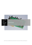
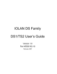
Table 5
Pinout of the front panel serial I/O ports config. for RS-232
1
6
9
5
Table 6
Pin
Signal
1
DCD (Data Carrier Detect, input)
2
RXD (Receive Data, input and output)
3
TXD (Transmit Data, output)
4
DTR (Data Terminal Ready, output)
5
GND (Ground)
6
DSR (Data Set Ready, input and output)
7
RTS (Request to Send, output)
8
CTS (Clear to Send, input)
9
GND (Ground, output): supplied by
FH-002 hybrid
Pinout of the front panel serial I/O ports config. for RS-422
1
6
Pin
Signal
1
TXD– (Transmit Data, output)
2
RTS– (Request to Send, output)
3
CTS+ (Clear to Send, input)
4
RXD+ (Receive Data, input)
5
GND (Signal GND)
6
TXD+ (Transmit Data, output)
7
RTS+ (Request to Send, output)
8
CTS– (Clear to Send, input)
9
RXD– (Receive Data, input)
9
5
SYS68K/CPU-60
Page 19
Serial I/O Ports – SCC
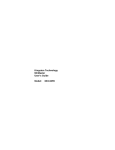
Table 7
Installation
Pinout of the front panel serial I/O ports config. for RS-485
1
6
9
5
IMPORTANT
Pin
Signal
1
RX-, TX-
2
GND
3
To be connected to GND via RS-485
cable
4
n.c.
5
GND
6
RX+, TX+
7
To be connected to GND via RS-485
cable
8
GND
9
n.c.
In case of the RS-485 configuration connect the pins 3 and 7 to GND via
the RS-485 cable, e.g. by connecting them to the pins 2 and 8, respectively.
i
Default port
setup
• FH-002 installed for RS-232 support
• Asynchronous communication
• 9600 Baud, 8 data bits, 1 stop bit, no parity
• Hardware handshake protocol
Interface options
To easily vary the serial I/O interfaces according to the application’s
needs FORCE COMPUTERS has developed RS-232, RS-422, and
RS-485 hybrid modules: the FH-002, FH-003/FH-422T, and FH-007.
The difference between FH-003 and FH-422T is that FH-422T has internal termination resistors. For each serial I/O port one of these 21-pin single in-line (SIL) hybrids is installed on-board:
• serial I/O port 1: hybrid installed in location J21
204077 2 – 3 June 1999
• serial I/O port 2: hybrid installed in location J22
Page 20
SYS68K/CPU-60
Installation
SCSI
After installing the correct hybrid for the port under consideration the
port has to be configured accordingly by using the appropriate switch setting. Thereby, the following options are selectable:
• FH-002 installed:
– RS-232 asynchronous
– RS-232 synchronous master
– RS-232 synchronous slave
• FH-003/FH-422T installed:
– RS-422
• FH-007 installed:
– RS-485
Switches
selecting serial
I/O options
The following switches apply to the port configuration:
• port 1: SW10-2, SW12-1, SW12-4 (see “SW10-2” on page 13),
• port 2: SW10-1, SW12-2, SW12-3 (see “SW10-1” on page 13).
2.8
SCSI
Device: SCSI 53C720SE
Frequency
CPU bus frequency
Package
PQ160
Accessible from
68060 CPU
Access address
FFF8.000016
Port width
Long
Interrupt request level
Software programmable
FGA-002 interrupt
Local IRQ #6
The SCSI 53C720SE provides an 8-bit SCSI interface which is routed to
the VMEbus P2 connector. The 8-bit SCSI interface at the VMEbus P2 is
pinout compatible to the CPU-30 and CPU-40 (with EAGLE-01 or EAGLE-10/11).
The local bus interface is 32-bit wide and able to transfer data via the
DMA controller of the SCSI 53C720SE.
SYS68K/CPU-60
Page 21
SCSI
Installation
The active termination can be selected by means of switches (see
“SW11-2” and “SW11-1” on page 14). TERMPWR is supported.
Factory option
A 16-bit single-ended SCSI interface (wide SCSI) which is routed to the
VMEbus P2 connector is available as factory option (see section 2.11
“VMEbus P2 Connector Pinout” on page 24). The wide-SCSI and the
SERIAL-2-on-P2 factory option are not available simultaneously.
SCSI Bus Termination
IMPORTANT
i
According to the SCSI specification, the interconnecting flat cable must
be terminated at both ends.
• Before connecting SCSI devices ensure correct SCSI bus termination:
– If the CPU board is not located at either end of the cable, the termination must be disabled.
– If the CPU board is located at the cable’s end, the termination must
be enabled.
On the SYS68K/CPU-60 the termination of the SCSI bus is done by active terminators with a disconnect feature. This allows the outputs to be
shut down to remove the terminator from the SCSI bus. It also reduces
the standby power.
The disconnect input of the terminators is controlled by SW11-1 and
SW11-2: default “OFF OFF = wide and 8-bit SCSI”, see page 14.
The power for the terminator of any SCSI device will be provided from
the CPU board directly, or from the SCSI bus itself. If the termination
power is not delivered from any other SCSI device, it is delivered from
the CPU board.
The TERMPWR (terminator power) supply from the CPU board is protected by a self-resetting fuse (1A max.) and a diode in series, as defined
in the SCSI specification.
The on-board terminators draw power from the SCSI bus TERMPWR.
204077 2 – 3 June 1999
SCSI bus
terminator power
Page 22
SYS68K/CPU-60
Installation
2.9
Floppy Disk – FDC
Floppy Disk – FDC
Device: FDC 37C65C
Frequency
16 MHz
Package
44-pin PLCC
Accessible from
68060 CPU
Access address
FF80.380016
Port width
Byte
Interrupt request level
Software programmable
FGA-002 interrupt
Local IRQ #1
The FDC signals are available at the VMEbus P2 connector (see
section 2.11 “VMEbus P2 Connector Pinout” on page 24).
An I/O back panel can be plugged onto the rear side of the backplane to
interface to standard FDC connectors (see section 2.12 “SYS68K/IOBP1” on page 28).
2.10 Ethernet – LAN
Device: LAN AM 79C965A
Frequency
68060 CPU bus frequency
Package
PQ160
Accessible from
68060 CPU
Access address
FFF0.000016
Port width
Word only in 16-bit mode,
long in 32-bit mode
Interrupt request level
Software programmable
FGA-002 interrupt
Local IRQ #7
The Ethernet AUI interface is available at the front panel via a 15-pin
D-Sub connector. As factory option Cheapernet is available via an SMB
connector instead of the Ethernet AUI interface.
SYS68K/CPU-60
Page 23
VMEbus P2 Connector Pinout
Installation
The CPU bus interface is 32-bit wide and able to transfer data via the
DMA controller of the AM 79C965A.
The following table shows the pinout of the factory default Ethernet connector:
Table 8
15-pin AUI-Ethernet connector
1
9
15
8
Ethernet address
Pin
Signal
1
GND
2
Collision +
3
Transmit data +
4
GND
5
Receive data +
6
GND
7
n.c.
8
GND
9
Collision –
10
Transmit data –
11
GND
12
Receive data –
13
+12 V DC
14
GND
15
n.c.
The CPU board’s Ethernet address is displayed in the banner when entering FGA Boot.
2.11 VMEbus P2 Connector Pinout
I/O signals
The I/O signal assignment on the VMEbus P2 connector allows interconnections using
• and the IOPI-2 (8-bit SCSI, floppy disk, and serial I/O – see the IOPI-2
User’s Installation Manual).
Page 24
SYS68K/CPU-60
204077 2 – 3 June 1999
• the SYS68K/IOBP-1 (8-bit SCSI, floppy disk, and serial I/O – see
section 2.12 “SYS68K/IOBP-1” on page 28)
Installation
VMEbus P2 Connector Pinout
IMPORTANT
i
In the following 2 figures unbracketed signals are available as factory default. Additionally,
• “*” marks the signals which are available with the wide SCSI factory
option. They are implemented via 0-Ohm resistors.
• “**” marks the signals which are available with the FDC eject factory
option.
• “***” marks the signals which are available with the SERIAL-2-on-P2
factory option.
• FDC DSEL1 is also available at C7 to provide backward compatibility
to FDC DESL3.
• FDC DSEL2 is also available at C3 to provide backward compatibility
to FDC DESL4.
• Instead of FDC DCHG, there formerly was FDC READY. However,
the manufacturers of floppy disk drives have agreed upon not supporting the FDC READY signal any longer and using FDC DCHG (disk
change) only.
Figure 3
P2 connector pinout with serial I/O config. for RS-232
A
SCSI Data 0
SCSI Data 1
SCSI Data 2
SCSI Data 3
SCSI Data 4
SCSI Data 5
SCSI Data 6
SCSI Data 7
SCSI DPA
GND
GND
GND
TERMPWR
GND
GND
SCSI ATN
GND
SCSI BSY
SCSI ACK
SCSI RST
SCSI MSG
SCSI SEL
SCSI CD
SCSI REQ
SCSI IO
n.c. (Serial TxD_2***)
n.c. (Serial GND_2***)
n.c. (Serial RxD_2***)
Serial DSR_1
Serial RTS_1
Serial CTS_1
Serial GND_1
SYS68K/CPU-60
C
1
5
10
15
20
25
30
32
FDC RPM
FDC HLOAD (FDC EJECT**)
FDC DSEL2
FDC INDEX
FDC DSEL1
FDC DSEL2
FDC DSEL1
FDC MOTOR
FDC DIREC
FDC STEPX
FDC WDATA
FDC WGATE
FDC TRK00
FDC WPROT
FDC RDATA
FDC SDSEL
FDC DCHG
n.c.
n.c.
n.c. (SCSI Data 8*)
SCSI Data 9
n.c. (SCSI Data 10*)
n.c. (SCSI Data 11*)
Serial DTR_2*** (SCSI Data 12*)
Serial DSR_2*** (SCSI Data 13*)
Serial RTS_2*** (SCSI Data 14*)
Serial CTS_2*** (SCSI Data 15*)
Serial DCD_2*** (SCSI DPB*)
Serial DCD_1
Serial RxD_1
Serial TxD_1
Serial DTR_1
Page 25
VMEbus P2 Connector Pinout
Figure 4
Installation
P2 connector pinout with serial I/O config. for RS-422
A
C
1
5
10
15
20
25
30
32
FDC RPM
FDC HLOAD (FDC EJECT**)
FDC DSEL2
FDC INDEX
FDC DSEL1
FDC DSEL2
FDC DSEL1
FDC MOTOR
FDC DIREC
FDC STEPX
FDC WDATA
FDC WGATE
FDC TRK00
FDC WPROT
FDC RDATA
FDC SDSEL
FDC DCHG
n.c.
n.c.
n.c. (SCSI Data 8*)
SCSI Data 9
n.c. (SCSI Data 10*)
n.c. (SCSI Data 11*)
Serial RXD+_2*** (SCSI Data 12*)
Serial TXD+_2*** (SCSI Data 13*)
Serial RTS+_2*** (SCSI Data 14*)
Serial CTS+_2*** (SCSI Data 15*)
Serial TXD–_2*** (SCSI DPB*)
Serial TXD–_1
Serial RTS–_1
Serial CTS+_1
Serial RXD+_1
204077 2 – 3 June 1999
SCSI Data 0
SCSI Data 1
SCSI Data 2
SCSI Data 3
SCSI Data 4
SCSI Data 5
SCSI Data 6
SCSI Data 7
SCSI DPA
GND
GND
GND
TERMPWR
GND
GND
SCSI ATN
GND
SCSI BSY
SCSI ACK
SCSI RST
SCSI MSG
SCSI SEL
SCSI CD
SCSI REQ
SCSI IO
n.c. (Serial CTS+_2***)
n.c. (Serial RXD–_2***)
n.c. (Serial RTS–_2***)
Serial TXD+_1
Serial RTS+_1
Serial CTS–_1
Serial RXD–_1
Page 26
SYS68K/CPU-60
Installation
VMEbus P2 Connector Pinout
Figure 5
P2 connector pinout with serial I/O config. for RS-485
A
SCSI Data 0
SCSI Data 1
SCSI Data 2
SCSI Data 3
SCSI Data 4
SCSI Data 5
SCSI Data 6
SCSI Data 7
SCSI DPA
GND
GND
GND
TERMPWR
GND
GND
SCSI ATN
GND
SCSI BSY
SCSI ACK
SCSI RST
SCSI MSG
SCSI SEL
SCSI CD
SCSI REQ
SCSI IO
n.c.
Serial RX-_2, TX-_2
GND
n.c.
n.c.
GND
Serial RX-_1, TX-_1
IMPORTANT
i
C
1
5
10
15
20
25
30
32
FDC RPM
FDC HLOAD (FDC EJECT**)
FDC DSEL2
FDC INDEX
FDC DSEL1
FDC DSEL2
FDC DSEL1
FDC MOTOR
FDC DIREC
FDC STEPX
FDC WDATA
FDC WGATE
FDC TRK00
FDC WPROT
FDC RDATA
FDC SDSEL
FDC DCHG
n.c.
n.c.
n.c. (SCSI Data 8*)
SCSI Data 9
n.c. (SCSI Data 10*)
n.c. (SCSI Data 11*)
Serial RX+_2, TX+_2
n.c.
n.c.
GND
Serial RX-_2, TX-_2
Serial RX-_1, TX-_1
GND
n.c.
Serial RX+_1, TX+_1
Serial 1, 2:
Note that
• the pins A30 and C31 must be connected to GND externally in case of
the serial-1 RS-485 configuration.
• the pins A26 and C26 must be connected to GND externally in case of
the serial-2 RS-485 configuration.
SYS68K/CPU-60
Page 27
SYS68K/IOBP-1
Installation
2.12 SYS68K/IOBP-1
As a separate price list item FORCE COMPUTERS offers a
SYS68K/IOBP-1 I/O panel which is plugged into the VMEbus backplane
from its rear.
NOTICE
!
Figure 6
To avoid damage to the board, do not use the SYS68K/IOBP-1 for the
SYS68K/CPU-60 if serial port #2 is configured as RS-422.
The SYS68K/IOBP-1 enables easy connection to the I/O signals which
are available on the CPU board’s P2 connector.
SYS68K/IOBP-1 pin assignment for VME P2
A
SCSI DB 0
SCSI DB 1
SCSI DB 2
SCSI DB 3
SCSI DB 4
SCSI DB 5
SCSI DB 6
SCSI DB 7
SCSI DB P
GND
GND
GND
SCSI TERMPWR
GND
GND
SCSI ATN
GND
SCSI BSY
SCSI ACK
SCSI RST
SCSI MSG
SCSI SEL
SCSI C/D
SCSI REQ
SCSI I/O
C
1
5
10
15
20
GND
GND
GND
GND
25
GND
SER DSR
SER RTS
SER CTS
SER GND
FDC Drive Select 4 (2)
FDC Index
FDC Drive Select 1
FDC Drive Select 2
FDC Drive Select 3 (1)
FDC Motor On
FDC Direction In
FDC Step
FDC Write Data
FDC Write Gate
FDC Track 000
FDC Write Protect
FDC Read Data
FDC Side Select
FDC Disk Change *
30
32
reserved
reserved
SER DCD
SER RXD
SER TXD
SER DTR
* Instead of FDC DCHG, there formerly was FDC READY (see note on page 25).
The SYS68K/IOBP-1 contains the following connectors:
• P2 for the standard SCSI interface,
• P3 for the floppy disk interface,
All row A and C pins of the VMEbus P2 connector are routed to the
64-pin male P4 connector on SYS68K/IOBP-1. However, the P4 connec-
Page 28
SYS68K/CPU-60
204077 2 – 3 June 1999
• and P5 for the serial I/O port 1.
Installation
SYS68K/IOBP-1
tor pinout differs from the VME P2 connector by the counting direction:
pin 1 of P4 = pin 32 of P2, …, pin 32 of P4 = pin 1 of P2.
SYS68K/CPU-60
Page 29
Testing the CPU Board Using VMEPROM
Installation
2.13 Testing the CPU Board Using VMEPROM
VMEPROM is a firmware providing a real-time multitasking multiuser
monitor program. It is stored in the on-board system PROM.
Booting up
VMEPROM
To start VMEPROM automatically during power up or reset, the
MODE 1 and MODE 2 rotary switches must both be set to F16. During
booting FGA Boot is executed. After the successful pass of the self-test
routine, the front-panel 7-segment hexadecimal display is switched off
and its decimal point is periodically switched on and off.
POST codes
If the SYS68K/CPU-60 fails during booting, the following POST (Power
On SelfTest) codes indicate the status at the time of failure. The POST
codes are displayed as status information during boot on the front-panel
7-segment hexadecimal display. The following table lists the POST codes
in the order they occur during booting.
Table 9
POST codes indicating boot status
Description
cryptic code
When a ‘cryptic’ code is displayed, a general hardware error occurred. FGA Boot cannot be started.
<Off>
Read board ID from port and initialize 7-segment
hexadecimal display.
0
Initialize the 68060 CPU registers CACR, ITTx, and
DTTx, disable caches. FGA Boot has already left the
boot-mode in this state.
1
Initialize the front-panel serial I/O port 1.
2
Initialize the CIO devices.
3
Identify board features and pre-select initialization sequence to follow. Read serial ID-ROM.
4
Determine CPU clock frequency (with cache enabled).
5
Determine capacity of main memory.
6
Verify local SRAM contents and store default values
if checksum is wrong.
7
Perform auto-configuration (check hardware for special conditions such as being plugged in slot-1).
If need, update SRAM value.
204077 2 – 3 June 1999
POST code
Page 30
SYS68K/CPU-60
Installation
Testing the CPU Board Using VMEPROM
Table 9
POST codes indicating boot status (cont.)
POST code
Description
8
Test for EAGLE modules (not applicable for
SYS68K/CPU-60).
9
Read front-panel rotary switches and store to SRAM.
A
Check for firmware to start (default VMEPROM).
b
If the abort key is asserted or if there is no firmware to
start, display the FGA Boot banner and start the shell.
C
Initialize FGA-002, arbiter, user LED and other hardware. Set up VMEbus A32 slave window (and A24 if
enabled).
d
Clear DRAM (fill with 0) to initialize parity.
E
Call user program.
F
Try to execute the firmware.
<Off>
Left FGA Boot, started firmware.
System
controller
If the board is configured as system controller (i.e. SYS68K/CPU-60 is
installed in slot 1), FGA Boot automatically enables the FGA-002 arbiter
and switches on the user LED.
Starting a test
after booting
To test the CPU board for correct operation enter the following command
after the ? prompt:
? SELFTEST
SELFTEST does not provide a full-featured power-on self-test. However, it tests some I/O devices, the main memory, and the system timer tick
interrupt. The time SELFTEST takes for testing depends on the main
memory’s size. Allow approximately one minute per Mbyte.
Correct
operation
After all tests have been done, the following message is displayed:
VMEPROM Hardware Selftest
------------------------I/O test ........ passed
Memory test ..... passed
Clock test ...... passed
SYS68K/CPU-60
Page 31
Installation
204077 2 – 3 June 1999
Testing the CPU Board Using VMEPROM
Page 32
SYS68K/CPU-60
Hardware
3
Hardware
The SYS68K/CPU-60 is a high performance single-board computer providing a 32-bit master/slave VMEbus interface including DMA. It is
based on
• the 68060 CPU (see section 3.4 “68060 CPU” on page 45),
• the FORCE gate array FGA-002 (see section 3.7 “FGA-002 Gate
Array” on page 51),
• and the VMEbus (see section 3.15 “VMEbus Interface” on page 75).
Described
features
The SYS68K/CPU-60 provides
• on-board shared DRAM (see section 3.8 “DRAM” on page 52)
• system PROM (see section 3.10 “System PROM” on page 62)
• boot PROM (see section 3.11 “Boot PROM” on page 64)
• on-board local SRAM (with on-board battery backup) (see
section 3.13 “Local SRAM” on page 69) and optional on-board user
SRAM (with on-board battery backup) (see section 3.9 “User SRAM
(factory option)” on page 61)
• on-board real-time clock (with on-board battery backup) (see
section 3.14 “Real-Time Clock – RTC 72423” on page 71)
• Ethernet interface, available at the front panel (see section 3.21 “Ethernet – LAN AM 79C965A” on page 96)
• single-ended SCSI interface and optional wide-fast-SCSI instead of the
standard SCSI interface (see section 3.19 “SCSI – 53C720SE” on
page 92)
• floppy interface (see section 3.20 “Floppy Disk – FDC 37C65C” on
page 94)
• two RS-232 serial I/O ports (see section 3.18 “Serial I/O – SCC AM
85C30” on page 89)
DMA controllers
The following devices are collectively referred to as DMA controllers of
the SYS68K/CPU-60 because they themselves provide an on-chip DMA
controller:
• FGA-002 Gate Array,
• SCSI – 53C720SE,
• and Ethernet – LAN AM 79C965A.
SYS68K/CPU-60
Page 33
Hardware
Front panel
The front panel of the SYS68K/CPU-60 provides an Ethernet port (see
section 3.21 “Ethernet – LAN AM 79C965A” on page 96) and 2 serial
ports (see section 3.18 “Serial I/O – SCC AM 85C30” on page 89). These
ports serve as console port, for download and for data communication.
Interfaces on
VMEbus P2
connector
The following interfaces are available on the 3-row VMEbus P2 connector (see section 2.11 “VMEbus P2 Connector Pinout” on page 24):
• serial port 1 and 2 (see section 3.18 “Serial I/O – SCC AM 85C30” on
page 89; note, however, that serial port 2 is only available if the wide
SCSI factory option is not installed),
• the SCSI interface (see section 3.19 “SCSI – 53C720SE” on page 92),
• and the floppy interface (see section 3.20 “Floppy Disk – FDC
37C65C” on page 94).
Factory options
The following factory options are available:
• capacity of DRAM (see section 3.8 “DRAM” on page 52 and
“DRAM” on page 2)
• on-board user SRAM (with on-board battery backup) (see section 3.9
“User SRAM (factory option)” on page 61 and “User SRAM” on
page 2)
• capacity of system PROM (see section 3.10 “System PROM” on
page 62 and “System PROM” on page 2)
• capacity and type of boot PROM (see section 3.11 “Boot PROM” on
page 64 and “Boot PROM” on page 2)
• capacity of local SRAM (see section 3.13 “Local SRAM” on page 69
and “Local SRAM” on page 3)
• capacity of user flash (see section 3.12 “User Flash” on page 68 and
“User flash” on page 3)
• SERIAL-2-on-P2 option wide-fast-SCSI instead of the standard SCSI
interface (see section 3.19 “SCSI – 53C720SE” on page 92): not available together with the SERIAL-2-on-P2 option.
Page 34
SYS68K/CPU-60
204077 June 1999; last documentation change with SYS68K/CPU-60 PCB Rev. 0.1
• wide-fast-SCSI instead of the standard SCSI interface (see section 3.19
“SCSI – 53C720SE” on page 92): not available together with the
SERIAL-2-on-P2 option.
Hardware
Figure 7
SYS68K/CPU-60 block diagram
68060
CPU
F
r
o
n
t
p
a
n
e
l
DRAM
on-board
MEM-60
RIALTO
bus bridge
(060/020)
Memory
Memory control
bus
System
PROM
FLXI bus
(020 bus)
I/O bus
CPU bus
(060 bus)
User
SRAM
FDC
Local SRAM
(NVRAM)
Ethernet
LAN
VESA local
bus (VL bus)
SCSI
(+ SCSIbus
Termin.)
AUX DMA
RTC
CIO
VL
adaption
FGA-002
Boot
PROM
User flash
(local flash)
V
M
E
b
us
SCC
4 LEDs
Hex. Displ.
2 rotary sw.
Reset key
Abort key
Serial I/O
1 and 2
SCSIbus
SYS68K/CPU-60
Page 35
SYS68K/CPU-60 Memory Map
3.1
Hardware
SYS68K/CPU-60 Memory Map
The SYS68K/CPU-60 is designed to utilize the entire 4-Gbyte address
space of the 68060 CPU.
As the following table and section 3.15.3 “Master Interface: Data Transfer Size” on page 78 show the memory map of the SYS68K/CPU-60 is
divided into address ranges for
• local memory,
• local I/O,
• FGA-002 internal registers,
• and the VMEbus address range (for the message broadcast area see
table 43 “Address ranges related to AM codes” on page 77).
IMPORTANT
i
• Before erasing or programming the system PROM ensure that you do
not destroy the VMEPROM image. The VMEPROM image resides in
the first 512 Kbyte of the system PROM starting at address
FF00.000016 and ending at FF08.000016.
• Before erasing or programming the boot PROM ensure that you do not
destroy the FORCE COMPUTERS FGA Boot image. Before erasing
or programming make a copy of the boot PROM device 1 in socket
J70.
• The Ethernet – LAN AM 79C965A decodes itself and uses only the
first 32 bytes. Accesses via this area are terminated by a bus error. All
other register address spaces are mirrored.
• Always remember the following access rule for any reserved bits in
any SYS68K/CPU-60 register: written as 0 read as undefined.
• All registers must be written or read using the data path width documented for the respective register.
204077 June 1999; last documentation change with SYS68K/CPU-60 PCB Rev. 0.1
• Always remember that in descriptions of data path widths byte refers
to 8 bit, word to 16 bit, and long to 32 bit
Page 36
SYS68K/CPU-60
Hardware
SYS68K/CPU-60 Memory Map
Address range
Device
Cache
Burst
SYS68K/CPU-60 memory map
VMEbus
accessible
Table 10
Access
width
0000.000016
…003F.FFFF16
DRAM: contributing to shared
RAM, address range depends on
memory capacity
Y
Y
Y
32/16/8
00xx.000016
…005F.FFFF16
User SRAM (factory option): contributing to the shared RAM, consecutive to DRAM
Y
Y
Y
32/16/8
00xx.000016
…FAFF.FFFF16
VME A32 extended address space
(consecutive to DRAM and user
SRAM)
n/a
N
Y
32/16/8
FB00.000016
…FBFE.FFFF16
VME A24 standard address space
n/a
N
Y
32/16/8
FBFF.000016
…FBFF.FFFF16
VME A16 short address space
n/a
N
Y
32/16/8
FC00.000016
…FCFE.FFFF16
VME A24 standard address space
n/a
N
Y
16/8
FCFF.000016
…FCFF.FFFF16
VME A16 short address space
n/a
N
Y
16/8
FD00.000016
…FEFF.FFFF16
reserved
n/a
n/a
n/a
n/a
FF00.000016
…FF3F.FFFF16
System PROM: address range depends on system flash capacity
N
Y
Y
32/16/8
SYS68K/CPU-60 Parameters and
Timers – CIO Z8536:
FF80.0C0016
…FF80.0DFF16
CIO1
N
N
N
8
FF80.0E0016
…FF80.0FFF16
CIO2
N
N
N
8
FF80.100016
Slot-1 status register (RO)
N
N
N
8
FF80.200016
…FF80.21FF16
Serial I/O – SCC AM 85C30
N
N
N
8
FF80.300016
…FF80.31FF16
Real-Time Clock – RTC 72423
N
N
N
8
FF80.380016
…FF80.39FF16
Floppy Disk – FDC 37C65C
N
N
N
8
SYS68K/CPU-60
Page 37
SYS68K/CPU-60 Interrupt Map
3.2
Address range
Device
Cache
Burst
SYS68K/CPU-60 memory map (cont.)
VMEbus
accessible
Table 10
Hardware
Access
width
FFC0.000016
…FFC7.FFFF16
Local SRAM
N
Y
N
32/16/8
FFC8.000016
…FFCF.FFFF16
User Flash
N
Y
N
32/16/8
FFD0.000016
…FFDF.FFFF16
FGA-002 Gate Array internal reg.
n/a
N
N
32/16/8
FFE0.000016
…FFEF.FFFF16
Boot PROM
N
Y
N
32/16/8
FFF0.000016
…FFF3.FFFF16
Ethernet – LAN AM 79C965A
N
N
N
32/16/8
FFF4.000016
…FFF7.FFFF16
Register area (see section 3.6
“RIALTO Bus Bridge” on page 50
and section 3.8.1 “Register Set” on
page 53 for memory control)
N
N
N
reg.
dependent
FFF8.000016
…FFFB.FFFF16
SCSI – 53C720SE
N
N
N
32/16/8
FFFC.000016
…FFFF.FFFF16
reserved
n/a
n/a
n/a
n/a
SYS68K/CPU-60 Interrupt Map
The FGA-002 monitors the VMEbus and all SYS68K/CPU-60 interrupt
requests (IRQ):
• interrupt requests of all seven VMEbus interrupt levels,
• interrupt requests from on-board devices, e.g., from the SCSI and the
floppy disk controller,
Page 38
ACFAIL* and
SYSFAIL*
Additionally, the VMEbus signals ACFAIL* and SYSFAIL* can be programmed to interrupt the CPU on a software programmable level.
Flexible interrupt
programming
Every interrupt source, including the VMEbus IRQs, can be programmed
to interrupt the CPU on an individually programmable priority level,
from 1 through 7.
The FGA-002 may supply the interrupt vector, or it may initiate an interrupt vector fetch from the I/O device or from the VMEbus.
SYS68K/CPU-60
204077 June 1999; last documentation change with SYS68K/CPU-60 PCB Rev. 0.1
• and the FGA-002 specific interrupt requests.
Hardware
SYS68K/CPU-60 Interrupt Map
FGA-002
supplied
interrupt vectors
Interrupt vectors supplied by the FGA-002 all share a basic vector and a
fixed vector offset for each source. The basic vector is software programmable.
The table below shows the local interrupt requests of the FGA-002 programmed for the local devices. For information on the vector offset and
on programming the IRQ level, refer to the FORCE Gate Array FGA-002
User’s Manual.
Table 11
SYS68K/CPU-60 interrupt map
Function
Device
FGA-002 IRQ
IRQ level
Vector
supplied
by
Watchdog timer
Memory control
LIRQ0
sw. prog.
FGA-002
Floppy disk
FDC 37C65C
LIRQ1
sw. prog.
FGA-002
Timer 3
CIO Z8536 (CIO1)
LIRQ2
sw. prog.
FGA-002
Timer 2
CIO Z8536 (CIO1)
LIRQ3
sw. prog.
FGA-002
CPU board
parameters
CIO Z8536 (CIO1 and
CIO2)
LIRQ4
sw. prog.
CIO or
FGA-002
SCC
SCC AM 85C30
LIRQ5
sw. prog.
SCC or
FGA-002
SCSI
SCSI 53C720SE
LIRQ6
sw. prog.
FGA-002
Ethernet
LAN AM 79C965A
LIRQ7
sw. prog.
FGA-002
SYS68K/CPU-60
Page 39
SYS68K/CPU-60 Parameters and Timers – CIO Z8536
3.3
Hardware
SYS68K/CPU-60 Parameters and Timers – CIO Z8536
Page 40
Parameters
The following parameters can be read or written:
– timers
• reading whether an interrupt request has been generated by one of the
timers 2 or 3 from CIO1 (see table 13 “CIO1 port C data register” on
page 41 and table 14 “CIO1 port B data register” on page 42),
– DRAM
• reading the DRAM capacity (see table 13 “CIO1 port C data register”
on page 41 and table 16 “CIO2 port C data register” on page 44),
– ID-ROM
• controlling and reading the status of the serial ID-ROM signals (see
table 14 “CIO1 port B data register” on page 42) for reading the CPUboard’s Ethernet address (see section 3.21 “Ethernet – LAN AM
79C965A” on page 96),
– MODE x
• reading the setting of the 2 front-panel rotary switches (see table 15
“CIO1 port A data register (including MODE x status register)” on
page 43),
– A24-to-A32
• controlling the availability of the automatic A24 expansion (see
table 16 “CIO2 port C data register” on page 44) and the A24-to-A32
address translation (see table 18 “CIO2 port A data register” on
page 45),
– board ID
• reading the CPU board identification number (see table 17 “CIO2 port
B data register” on page 44),
– DIAG
• controlling the front-panel DIAG 7-segment hexadecimal display (see
table 17 “CIO2 port B data register” on page 44),
CIO counters
and timers
CIO1 and CIO2 both offer 3 independently programmable 16-bit timers
with 500 ns resolution which can also be used as counters. For information on CIO1 timer 2 and 3 see section 3.3.1 “MEM-60 DRAM Capacity
and CIO1 Timer 3” on page 41 and section 3.3.2 “Flash VPP, Floppy
Disk Control, and CIO1 Timer 2” on page 42.
Clock
The peripheral clock of both CIO devices is connected to a 4 MHz
source.
IRQ
The interrupt request output of both CIO devices use LIRQ4 of the
FGA-002. The interrupt vectors are supplied by the CIO devices. CIO1
has the higher interrupt priority in the daisy chain.
CIO access
The CIO devices are accessible via the 8-bit local I/O bus (byte mode).
SYS68K/CPU-60
204077 June 1999; last documentation change with SYS68K/CPU-60 PCB Rev. 0.1
The configuration and status information for several SYS68K/CPU-60
parameters and six 16-bit timers are accessible via 2 CIO Z8536 (see data
sheet “CIO Z8536” in section 5).
Hardware
SYS68K/CPU-60 Parameters and Timers – CIO Z8536
Table 12
SYS68K/CPU-60 parameters and timers register map and CIO loc.
Address
CIO
On-board
device location
Register name
FF80.0C0016
1
CIO1 port C data reg.
FF80.0C0116
CIO1 port B data reg.
FF80.0C0216
CIO1 port A data reg.
FF80.0C0316
CIO1 ctrl. and pointer reg. (see data
sheet “CIO Z8536” in section 5)
FF80.0E0016
3.3.1
J35
2
J34
CIO2 port C data reg.
FF80.0E0116
CIO2 port B data reg.
FF80.0E0216
CIO2 port A data reg.
FF80.0E0316
CIO2 ctrl. and pointer reg. (see data
sheet “CIO Z8536” in section 5)
MEM-60 DRAM Capacity and CIO1 Timer 3
Table 13
CIO1 port C data register
FF80.0C0016
Bit
7
6
5
4
Value
used as masking bits for write
accesses to bit 3…0 (e.g.: if bit 4
is 1, bit 0 cannot be written)
3
MC[2…0]
2
1
0
T3IRQ
MC[2…0]
(RO)
MC[2…0] indicate the capacity of the DRAM installed on the MEM-60
memory module (see section 3.8.5 “Reading the DRAM Capacity” on
page 57).
T3IRQ
(W)
T3IRQ controls the interrupt request output for timer 3 of CIO1. The
16-bit timer can generate interrupt requests at a software programmable
level (the FORCE Gate Array FGA-002 User’s Manual). The corresponding interrupt request line is connected to the local IRQ #2 of the
FGA-002. Additionally, the timer 3 of CIO1 can be programmed to generate an interrupt on the interrupt request line which is connected to the
local IRQ #4 of the FGA-002. For information on the interpretation of the
bit value of T3IRQ see data sheet “CIO Z8536” in section 5 and the
FORCE Gate Array FGA-002 User’s Manual.
SYS68K/CPU-60
Page 41
SYS68K/CPU-60 Parameters and Timers – CIO Z8536
3.3.2
Hardware
Flash VPP, Floppy Disk Control, and CIO1 Timer 2
Table 14
CIO1 port B data register
Bit
7
6
5
ID_SCL ID_SDA FLVPP
Value
Page 42
4
3
2
1
0
F_DCH
GEN
F_
ADDIR
F_
PCVAL
F_
DRV
T2IRQ
ID_SCL
(W)
ID_SCL controls the ID-ROM SCL signal (I2C bus), see “Ethernet node
address” on page 97.
ID_SDA
(R/W)
ID_SDA controls and indicates the status of the ID-ROM serial data signal (I2C bus), see “Ethernet node address” on page 97.
FLVPP
(W)
FLVPP controls whether the 12V programming voltage VPP for the flash
memory (system PROM, boot PROM, and user flash) is turned on.
=0
VPP is turned on.
=1
VPP is turned off.
F_xxxxxx
(W)
F_DCHGEN, F_ADDIR, F_PCVAL, and F_DRV control the FDC37C65C
floppy disk drive interface (for the signals related to F_DCHGEN,
F_PCVAL, and F_DRV see section 3.20 “Floppy Disk – FDC 37C65C”
on page 94).
– F_DRV
DRV signal
– F_PCVAL
PCVAL signal
– F_ADDIR
F_ADDIR controls the AUX DMA transfer direction:
=0
DMA write to FDC.
=1
DMA read from FDC.
– F_DCHGEN
DCHGEN signal
T2IRQ
(W)
T2IRQ controls the interrupt request output for timer 2 of CIO1. The
16-bit timer can generate interrupt requests at a software programmable
level. Timer 2 can be linked with timer 1 to establish a 32-bit timer. The
corresponding interrupt request line is connected to the local IRQ #3 of
the FGA-002. Additionally, the timer 2 of CIO1 can be programmed to
generate an interrupt on the interrupt request line which is connected to
the local IRQ #4 of the FGA-002. For information on the interpretation of
the bit value of T2IRQ see data sheet “CIO Z8536” in section 5 and the
FORCE Gate Array FGA-002 User’s Manual.
SYS68K/CPU-60
204077 June 1999; last documentation change with SYS68K/CPU-60 PCB Rev. 0.1
FF80.0C0116
Hardware
3.3.3
SYS68K/CPU-60 Parameters and Timers – CIO Z8536
MODE x Rotary Switch Setting
Rotary switches
– reset and abort
The MODE x rotary switches serve a special function in conjunction with
the reset and abort keys. This function is built into the boot PROM and is
described in detail in the boot software description of the FORCE Gate
Array FGA-002 User’s Manual.
– applications
For application programs, the rotary switches can be used as a general
purpose input channel for diagnostics, configuration selection, or automatic system boot with different configurations.
– VMEPROM
VMEPROM uses the rotary switches for automatic configuration (see
section 6.2.3 “Rotary Switches” on page 128).
Table 15
CIO1 port A data register (including MODE x status register)
FF80.0C0216
Bit
7
6
Value
RS2B[3…0]
5
4
3
2
1
0
RS1B[3…0]
RS2B[3…0] is commonly referred to as MODE 2 status register indicating the setting of the MODE 2 front-panel rotary switch:
RS2B[3…0]
(RO)
= F16
MODE 2 is set to F.
= E16
MODE 2 is set to E.
…
…
RS1B[3…0] is commonly referred to as MODE 1 status register indicating the setting of the MODE 1 front-panel rotary switch:
RS1B[3…0]
(RO)
= F16
MODE 1 is set to F.
= E16
MODE 1 is set to E.
…
…
SYS68K/CPU-60
Page 43
SYS68K/CPU-60 Parameters and Timers – CIO Z8536
3.3.4
Hardware
On-board DRAM Capacity and Automatic A24 Expansion
Table 16
CIO2 port C data register
FF80.0E0016
3.3.5
Bit
7
6
5
4
Value
used as masking bits for write
accesses to bit 3…0 (e.g.: if bit 4
is 1, bit 0 cannot be written)
3
2
1
MC[2…0]
0
A24E
MC[2…0]
(RO)
MC[2…0] indicate the capacity of the installed on-board DRAM (see
section 3.8.5 “Reading the DRAM Capacity” on page 57).
A24E
(W)
A24E controls the availability of the A24 expansion.
=0
A24 expansion enabled (A24 and A32 enabled).
=1
A24 expansion disabled (only A32 enabled).
Board ID and DIAG Display
Table 17
CIO2 port B data register
Bit
7
6
5
4
3
2
1
0
Value
DP
SEG_G
SEG_F
SEG_E
SEG_D
SEG_C
SEG_B
SEG_A
DP and
SEG_G
…SEG_A (R/W)
Page 44
When reading these bits directly after power-up or reset these bits indicate the CPU board identification number which is assigned to every type
of CPU board. The CPU identification number does not identify the factory options which might be available for CPU speeds, memory capacity,
or installed modules. In case of the SYS68K/CPU-60 the CPU board
identification number is 4010 = 2816 = 10.10002.
After the first reading of these bits the bits control the status of the decimal point (DP) and the segments (SEG_G…SEG_A) in the front-panel
hexadecimal display (see figure below for naming conventions).
= 0
The respective part of the display is turned off.
= 1
The respective part of the display is turned on.
SYS68K/CPU-60
204077 June 1999; last documentation change with SYS68K/CPU-60 PCB Rev. 0.1
FF80.0E0116
Hardware
68060 CPU
Figure 8
Naming the parts of the front-panel hexadecimal display
…_A
…_F
…_B
…_G
…_E
…_C
…_D
3.3.6
DP
A24-to-A32 Address Translation
Table 18
CIO2 port A data register
FF80.0E0216
Bit
7
Value
A[31…24]
A[31…24]
(W)
3.4
6
5
4
3
2
1
0
If the automatic A24 expansion is enabled (see table 16 “CIO2 port C
data register” on page 44), A[31…24] control the status of the A31…24
address lines (see section 3.15.7 “Slave Interface: Address Modifier Decoding and A24 Slave Mode” on page 81).
68060 CPU
The 68060 CPU is one of the fundamental components of the
SYS68K/CPU-60. Therefore, the M68060 User’s Manual is delivered together with this Technical Reference Manual.
3.4.1
Hardware Interface of the 68060 CPU
The 68060 CPU uses a non-multiplexed address and data bus. The bus interface supports synchronous data transfers between the CPU and other
devices in the system.
CPU-driven
signals
The CPU drives the address signals (A0 – A31), the size signals (SIZ0,
SIZ1) and the transfer cycle modifier (TM0 – TM2) on every cycle, independently of a cache hit or miss. These signals are used to decode the
memory map of the CPU board.
The hardware on the CPU board is notified by the address and data strobe
signals that the current cycle is not a cache cycle and that the decoding
outputs are strobed to be valid.
The 32 data lines (D0 – D31) are also driven by the 68060 CPU on write
cycles.
SYS68K/CPU-60
Page 45
68060 CPU
3.4.2
Hardware
CPU sensed
signals
The 32 data lines (D0 – D31) are sensed on read cycles. The size of the
data transfer is defined by the SIZE output signals (always driven by the
68060 CPU). Cycles are acknowledged by the transfer acknowledge (TA)
signal.
Bus error
generation
In case of bus operation a bus error will be generated if a device does not
respond correctly.
Bus error sensing
A bus error is sensed by the CPU via the TEA signal. If a bus error occurs, the current cycle is aborted (illegal transfer or incorrect data) and
exception handling starts. VMEbus transfers may also be aborted via
TEA.
If TA and TEA are sensed simultaneously, the CPU enters the retry bus
operation sequence. A retry happens, whenever the CPU tries to access a
device on the I/O bus or the VMEbus and an external master accesses the
shared RAM simultaneously.
Instruction Set of the 68060 CPU
For the 68060 CPU instruction set and for further information concerning
programming, refer to the 68060 User's Manual.
3.4.3
Vector Table of the 68060 CPU
This table lists all vectors defined and used by the 68060 CPU.
Page 46
68060 CPU exception vector assignments
Vector
number(s)
Vector
offset (Hex)
Assignment
0
1
00016
00416
Reset initial interrupt stack pointer
Reset initial program counter
2
3
00816
00C16
Access fault (bus error)
Address error
4
5
6
7
8
9
01016
01416
01816
01C16
02016
02416
Illegal instruction
Integer divide by zero
CHK, CHK2 instruction
TRAPcc, TRAPV instructions
Privilege violation
Trace
SYS68K/CPU-60
204077 June 1999; last documentation change with SYS68K/CPU-60 PCB Rev. 0.1
Table 19
Hardware
68060 CPU
Table 19
68060 CPU exception vector assignments (cont.)
SYS68K/CPU-60
Vector
number(s)
Vector
offset (Hex)
10
02816
11
02C16
12
03016
Emulator interrupt
13
14
15
03416
03816
03C16
unused by MC68060
Format error
Uninitialized interrupt
16 – 23
04016…05C16
reserved (unassigned)
24
06016
25
26
27
28
29
30
31
06416
06816
06C16
07016
07416
07816
07C16
Spurious interrupt
Interrupt autovector for level
1
2
3
4
5
6
7
32 – 47
08016…0BC16
TRAP #0 – 15 instruction vectors
48
49
50
51
52
53
54
55
0C016
0C416
0C816
OCC16
ODO16
OD416
0D816
ODC16
FPCP
branch or set on unordered condition
inexact result
divide by zero
underflow
operand error
overflow
signalling SNAN
unimplemented data type
56
57
58
0E016
0E416
0E816
unused by MC68060
Defined for 68852, unused by 68060
Defined for 68852, unused by 68060
59
0EC16
reserved (unassigned)
60
61
0F016
0F416
Unimplemented effective address
Unimplemented integer instruction
62 – 63
0F816…0FC16
reserved (unassigned)
64 – 255
10016…3FC16
User defined vectors (192)
Assignment
Line 1010 emulator
(unimplemented A-line opcode)
Line 1111 emulator
(unimplemented F-line opcode)
Page 47
Watchdog Timer
3.5
Hardware
Watchdog Timer
There is a watchdog timer installed on the SYS68K/CPU-60 to monitor
the 68060 CPU activity. The watchdog timer is able
• to issue an interrupt to the 68060 CPU
• and to generate a pseudo power up pulse whereby the CPU board is
reset but in contrast to a normal power up the on-board LCAs are not
loaded from the serail PROM.
One timeout is specified for both actions.
IRQ
The watchdog interrupt is the LIRQ0 input of the FGA-002.
IMPORTANT
This input must be configured
i
3.5.1
• to be sensitive on a falling edge signal
• and to generate level-7 interrupts to the 68060 CPU.
Watchdog Operation
Page 48
Trigger event
The watchdog timer is triggered by setting the RESTART bit in the
watchdog retrigger register to 0 (see table 21 “Watchdog retrigger register (WDR)” on page 49).
Timeout
The watchdog timeout is selectable by setting the WDTIME bit in the
memory configuration register (see table 26 “MCR, memory configuration register” on page 54): either 40 ms (± 30 %) or 0.5 s (± 30 %).
Starting the
watchdog
The watchdog timer is started by setting the ENWD bit in the memory configuration register (see table 26 “MCR, memory configuration register”
on page 54). Once started, it cannot be stopped unless a reset occurs. In
case of a reset the watchdog timer is automatically disabled.
If the retrigger event occurs within the watchdog timeout period, the
watchdog timer is restarted.
NMI generation
If the retrigger event does not occur within the watchdog timeout period,
the watchdog timer generates an NMI to the 68060 CPU.
If the retrigger event occurs within the watchdog timeout period after
generating the NMI, the watchdog timer is restarted.
SYS68K/CPU-60
204077 June 1999; last documentation change with SYS68K/CPU-60 PCB Rev. 0.1
The SYS68K/CPU-60 watchdog timer monitors the 68060 CPU activity
by awaiting a trigger event from the 68060 CPU within the watchdog
timer’s timeout period.
Hardware
3.5.2
Watchdog Timer
Timeout period
after NMI – reset
If the retrigger event does not occur within the watchdog timeout period
after generating the NMI, the watchdog timer generates a pseudo power
up pulse, thereby automatically stopping itself. It then must be restarted
by setting the ENWD bit in the memory configuration register as already
stated above.
Reset
To enable detection of a watchdog reset the watchdog NMI handler has to
clear the WDIRQ bit in the memory diagnostic register on every watchdog
interrupt (see table 27 “Memory diagnostic register (MDR)” on page 55).
A watchdog reset can then be detected by reading the WDIRQ bit.
Watchdog Register Map
The watchdog timer is controlled by the contents of the following registers:
Table 20
Watchdog register map (superset of the memory controller register
map)
Table 21
Address
Register name and access
FFF4.000816
Memory configuration reg. (MCR), R/W, see table 26
“MCR, memory configuration register” on page 54
FFF4.000A16
Watchdog retrigger reg. (WDR), WO
FFF4.000B16
Memory diagnostic reg. (MDR), RO, see table 27
“Memory diagnostic register (MDR)” on page 55
Watchdog retrigger register (WDR)
FFF4.000A16
Bit
7
6
5
4
3
reserved
Value
2
1
0
RESTART
RESTART retriggers the watchdog timer.
RESTART
(WO)
= 0
Retriggers the watchdog timer.
= 1
No action is taken.
SYS68K/CPU-60
Page 49
RIALTO Bus Bridge
3.6
Hardware
RIALTO Bus Bridge
The bus bridge is intended to maximize the performance of the CPU
board. As data and address bridge between the 68040-type CPU bus and
the FGA-002 interface chip the RIALTO bus bridge is especially designed to support fast VMEbus master/slave block transfers.
Revision of
RIALTO bus
bridge
3.6.1
After power up the SNOOP[2..0] bits in the bridge configuration register (BCR) show the revision of the RIALTO bus bridge (see section 3.6.2
“Bridge Configuration Register” on page 50).
Register Set
The following register map shows all internal registers and their corresponding register addresses.
Table 22
3.6.2
RIALTO bus bridge register map
Offset addr.
Reset value
Register name
FFF4.000016
0000.000016
reserved
FFF4.000416
00xx.xxxx16
Bridge configuration reg. (BCR)
Bridge Configuration Register
The bridge configuration register of the RIALTO bus bridge features several status and control bits to monitor and control the configuration.
Table 23
Bridge configuration register (BCR)
FFF4.000416
7
6
reserved
Value
4
3
2
1
LAN
DEC
USER
LED
SNOOP[2..0]
0
LANDEC defines the Ethernet decoding space (see section 3.21.1 “Register Access” on page 98).
LANDEC
(R/W)
Page 50
5
= 0
Ethernet decoding space is FFF0.000016…FFF3.FFFF16.
= 1
Ethernet decoding space is 0000.000016…0003.FFFF16.
SYS68K/CPU-60
204077 June 1999; last documentation change with SYS68K/CPU-60 PCB Rev. 0.1
Bit
Hardware
FGA-002 Gate Array
Controls the front-panel UL LED.
USERLED
(R/W)
= 0
LED is on.
= 1
LED is off.
SNOOP[2..0]
(R/W)
The snoop bits shrink the DRAM accessible from the VMEbus to the value listed in the table. This is done be masking out the higher address
lines. After power up the SNOOP[2..0] bits show the revision of the
RIALTO bus bridge.
Table 24
Snoop window definition in BCR
SNOOP [2..0] Snoop window
3.7
0
0
0
0
0
0
1
1
0
1
0
1
32
16
8
4
Mbyte
Mbyte
Mbyte
Mbyte
1
1
1
1
0
0
1
1
0
1
0
1
2
256
128
64
Mbyte
Mbyte
Mbyte
Mbyte
FGA-002 Gate Array
The FGA-002 controls the I/O bus and builds the interface to the VMEbus. It also includes
• a DMA controller,
• complete interrupt management,
• a message broadcast interface (FMB),
• timer functions,
• and mailbox locations.
Monitoring the
020 bus
The FGA-002 monitors the 020 bus. When any local device is accessed
the FGA-002 takes charge of all control signals in addition to the address
and data signals used.
Managing the
VMEbus
The FGA-002 serves as manager for the VMEbus. All VMEbus address
and data lines are connected to the gate array via buffers. Additional
functions such as the VMEbus interrupt handler and arbiter are also installed on the FGA-002.
SYS68K/CPU-60
Page 51
DRAM
3.8
Hardware
Start address
The start address of the FGA-002 registers is FFD0.000016.
Registers
For a detailed description of the FGA-002 registers, see the FORCE Gate
Array FGA-002 User’s Manual.
DRAM
The CPU board provides shared dynamic RAM (DRAM). For the available capacity options see “DRAM” on page 2. The DRAM capacity currently installed is software readable (see section 3.8.5 “Reading the
DRAM Capacity” on page 57).
The DRAM is optimized for fast accesses from the 68060 CPU and the
SCSI and Ethernet DMA controllers (see section 3.8.4 “DRAM Performance” on page 56). Snooping is supported.
IMPORTANT
i
Accessibility
To guarantee the cache coherence of the DRAM, it is necessary to configure the snoop window in the bridge configuration register of the RIALTO
bus bridge (see section 3.8.7 “Cache Coherence and Snooping” on
page 58).
The DRAM is accessible from the
• 68060 CPU (including burst mode support),
• FGA-002 Gate Array DMA controller,
• SCSI – 53C720SE DMA controller (including burst mode support),
• Ethernet – LAN AM 79C965A DMA controller,
Page 52
Burst mode
Burst mode support is always enabled. Advanced on-board memory control logic routes data to and from the 68060 CPU, the SCSI controller,
and the VMEbus interface.
DRAM read,
parity support
For every read cycle all 32 data and all 4 parity bits are read from the
DRAM, regardless of size (byte, word, long-word, or cache line) and regardless of master (68060 CPU, DMA controllers, or VMEbus). The 32
data and 4 parity bits are stored in the memory controller.
Parity is regenerated in the memory controller and compared to the parity
bits read from memory. If a parity error is detected for an accessed byte, a
bus error acknowledge is generated and a parity-error flag is set in the
memory controller (see table 27 “Memory diagnostic register (MDR)” on
page 55).
SYS68K/CPU-60
204077 June 1999; last documentation change with SYS68K/CPU-60 PCB Rev. 0.1
• and also from other VMEbus masters.
Hardware
3.8.1
DRAM
DRAM write
Write cycles are handled differently:
In case of a long-word access, the DRAM can be written immediately –
including the parity info generated by the memory control. A transfer acknowledge (TA) signal is asserted and the cycle completed.
For all other write cycles (byte, word) the currently valid parity bits
stored in the DRAM must be read at first. In order to satisfy this condition, only the necessary data will be written, the remaining data already
stored in DRAM memory will stay unmodified. Additionally, the new
parity bits generated by the memory controller will be merged with the
parity bits read from DRAM memory and finally all four parity bits are
written to DRAM memory. The transfer acknowledge (TA) signal is asserted and the cycle completed.
Write posting
All write cycles are terminated before they are fully processed so that the
master which is writing to DRAM can continue its operations (write posting).
Register Set
The following register map shows all internal registers and their corresponding register addresses.
Table 25
Memory controller register map (included in the watchdog register
map)
Offset addr.
Reset value
Register name
FFF4.000816
xx00.00xx.x
xx0.00002
Memory configuration (MCR)
Reset value:
xx00.00xx.xxx0.00002
FFF4.000B16
xxxx.xx0016
Memory diagnostic register (MDR)
Reset value:
aaaa.a0002
a depends on the actual version purchased (see table 27 “Memory diagnostic register (MDR)” on page 55)
SYS68K/CPU-60
Page 53
DRAM
3.8.2
Hardware
Memory Configuration Register
The memory configuration register provides several bits to control the
configuration of the memory controller.
Table 26
MCR, memory configuration register
FFF4.000816
Bit
15..14
13
reser- WD
ved
TIME
12
11
10
9..5
ENWD
RESET
OUT
ENPAR
VMEBUS
reser- VERS
TIMER
ved
MEM
[1..0]
CTRL
[4..2]
Value
1..0
WDTIME defines the watchdog timeout period.
WDTIME
(R/W)
= 0 (default)
=1
40 ms (± 30 %)
0.5 s (± 30 %)
ENWD starts the watchdog timer if set to 1. This bit can only be set to 1 or
read (setting it to 0 is impossible). A reset of the SYS68K/CPU-60 clears
this bit automatically.
ENWD
(R/W)
= 0
Watchdog timer is disabled.
= 1
Watchdog timer has been started.
RESETOUT controls the generation of a reset. If the RESETOUT bit in the
memory configuration register is set to 1, a reset is generated. Setting
the RESETOUT bit has the same effect as a reset generated by the watchdog timer.
RESETOUT
(R/W)
= 0
No action is taken.
= 1
Generates a reset.
= 0
DRAM parity check is disabled.
= 1
DRAM parity check is enabled.
VERSMEMCTRL
[4..2] (RO)
VERSMEMCTRL indicates the version memory control.
= 08
8th revision of memory control
= …8
…
= 78
1st revision of memory control.
SYS68K/CPU-60
204077 June 1999; last documentation change with SYS68K/CPU-60 PCB Rev. 0.1
ENPAR controls whether DRAM parity check is enabled (see “ENPARIN” on page 55).
ENPAR
(R/W)
Page 54
4..2
Hardware
DRAM
VMEBUSTIMER
[1..0] (R/W)
3.8.3
VMEBUSTIMER[1..0] controls the VME bustimer timeout (see
section 3.17.5 “VMEbus Timer” on page 89).
= 00
The VME bustimer is disabled.
= 01
timeout = 82 µs (± 10 %) for 25 MHz CPU bus frequency
timeout = 65 µs (± 10 %) for 33 MHz CPU bus frequency
= 10
timeout = 164 µs (± 10 %) for 25 MHz CPU bus frequency
timeout = 130 µs (± 10 %) for 33 MHz CPU bus frequency
= 11
timeout = 328 µs (± 10 %) for 25 MHz CPU bus frequency
timeout = 260 µs (± 10 %) for 33 MHz CPU bus frequency
Memory Diagnostic Register
The memory diagnostic register provides the monitoring of several status
flags.
IMPORTANT
A write access to MDR or a power up clears bit 3…0 in the MDR. They
are not cleared on a normal reset.
i
Table 27
Memory diagnostic register (MDR)
FFF4.000B16
Bit
7
6
5
4
3
2
1
0
SEL
25M
ENPAR
IN
SIBK
WESYS
FLASH
WDIRQ
CPUBT
BTF
PERR
Value
SEL25M indicates the 68060 CPU speed.
SEL25M
= 0
33 MHz.
= 1
25 MHz.
ENPARIN indicates the setting of SW9-2 for DRAM parity check (see
“ENPAR (R/W)” on page 54). When reading this bit the software should
set the ENPAR bit accordingly. FGA Boot conforms to this rule and enables or disables DRAM parity check according to the setting of the
ENPARIN bit.
ENPARIN
= 0
DRAM parity check should be disabled by software.
= 1
DRAM parity check should be enabled by software.
SIBK indicates whether a single or both DRAM banks are assembled.
SIBK
= 0
Both DRAM banks are assembled.
= 1
Only DRAM bank 1 is assembled.
SYS68K/CPU-60
Page 55
DRAM
Hardware
WESYSFLASH
= 0
SW10-3 is set to ON.
= 1
SW10-3 is set to OFF (OFF = writing enabled).
WDIRQ flags that a watchdog interrupt has been generated.
To enable detection of a watchdog reset the watchdog NMI handler has to
clear WDIRQ on every watchdog interrupt. A watchdog reset can then be
detected by reading the WDIRQ bit.
WDIRQ
= 0
No watchdog interrupt occurred.
= 1
A watchdog interrupt has been generated.
CPUBT indicates whether a bus error occurred – the CPU bustimer terminates cycles on the CPU bus by generating a timeout bus error.
CPUBT
= 0
No bus error occurred.
= 1
A bus error has been generated.
BTF, write burst to flash. This bit is set in case of a write burst to the system flash.
BTF
= 0
No BTF bus error detected.
= 1
A BTF bus error has occured.
PERR, parity bus error. This bit is set whenever a parity error is detected.
PERR
3.8.4
WESYSFLASH indicates the current setting of SW10-3, thereby indicating whether write access to the system PROM is enabled.
= 0
No parity error detected.
= 1
A parity error has occured.
DRAM Performance
Page 56
"5-1-1-1" burst
transfer
The first read cycle of such a burst usually requires 5 CPU clock cycles
(200 ns at 25 MHz). Due to the optimized design of the memory control
logic, each subsequent cycle only requires 1 CPU clock cycle (40 ns) to
complete. This is commonly called a "5-1-1-1" burst transfer. Overall, the
total cache line "burst fill" operation requires 8 clock cycles to transfer
16 bytes, providing a memory bandwidth of over 50 Mbyte/s.
Single read and
write
Not all CPU accesses are burst transfers. Single read and write transactions are also supported at maximum speed. A single read or write access
(1, 2, or 4 bytes) requires 5 CPU clock cycles. Distributed asynchronous
SYS68K/CPU-60
204077 June 1999; last documentation change with SYS68K/CPU-60 PCB Rev. 0.1
The on-board memory control logic is optimized for fast accesses from
the 68060 CPU providing the maximum performance. Since the 68060
CPU contains an on-chip data and instruction cache many CPU accesses
are cache line "burst fills". Within four 4-byte cycles these burst fills attempt to read 16 consecutive bytes into the 68060 CPU.
Hardware
DRAM
refresh is provided every 14 µs and an access during a pending refresh
cycle may be delayed by a maximum of 5 additional clock cycles.
3.8.5
Reading the DRAM Capacity
The installed on-board and the MEM-60 DRAM capacity are encoded in
3 bits (see MC[2…0] in “CIO2 port C data register” on page 44 and
MC[2…0] in “CIO1 port C data register” on page 41, respectively).
Table 28
DRAM capacity encoding at CIOx port C data registers
DRAM capacity
• on-board (when reading MC[2…0] from CIO2 port
C data register)
• on MEM-60 (when reading MC[2…0] from CIO1
port C data register)
MC[2…0]
3.8.6
0
0
0
32 Mbyte
0
0
1
16 Mbyte
0
1
0
8 Mbyte
0
1
1
4 Mbyte
1
0
0
0 Mbyte (no memory module plugged, resp.)
1
0
1
256 Mbyte
1
1
0
128 Mbyte
1
1
1
64 Mbyte
DRAM Organization
MEM-60 and onboard memory
banks
The DRAM is mounted on-board or on the MEM-60 memory module.
The on-board DRAM is arranged in 1 or 2 memory banks depending on
the available overall memory capacity. Each memory bank is 36-bit wide
– 32 data bits plus 4 parity bits.
SYS68K/CPU-60
Page 57
DRAM
Hardware
Table 29
DRAM device types and number of used banks
DRAM device
Total
capacity
No. of
banks
Product
Type1)
Capacity
CPU-60D/4
1M * 4 FPM
9 * 1 Mbit * 4
4 Mbyte 1
CPU-60D/8
1M * 4 FPM
18 * 1 Mbit * 4
8 Mbyte 2
CPU-60D/16 4M * 4 FPM
9 * 4 Mbit * 4
16 Mbyte 1
CPU-60D/32 4M * 4 FPM
18 * 4 Mbit * 4
32 Mbyte 2
1. FPM: Fast Page Mode
IMPORTANT
i
Bank selection
The bank selection depends on the number of installed memory banks:
– interleaved
• The dual-banks architecture implements an interleaved memory organization of the DRAM: 4 consecutive bytes located in bank 1, the next
4 consecutive bytes in bank 2, etc.
– non-interleaved
• The single-bank architecture implements a non-interleaved memory
organization of the DRAM: every 4 consecutive bytes located in
bank 1.
Cache Coherence and Snooping
To maintain cache coherence in a multimaster system, the 68060 CPU
has the capability of snooping. On a snooped external bus cycle the
68060 CPU invalidates the cache line that is hit. Supplying dirty data and
sinking dirty data is not supported by the 68060 CPU. Snoop hits invalidate the cache line in all cases (also for alternate master read/write cycles).
The snooping protocol supported by the 68060 CPU requires that memory areas shared with any other bus master is marked as ’cacheable writethrough’ or ’cache inhibited’.
Page 58
SYS68K/CPU-60
204077 June 1999; last documentation change with SYS68K/CPU-60 PCB Rev. 0.1
3.8.7
A parity bit checks every eight consecutive data bits (byte parity). The
DRAM parity check is only performed when SW9-2 is set appropriately:
OFF = enabled (default “OFF”, see page 13).
Hardware
DRAM
IMPORTANT
i
Unpredictable errors
Wrong configuration of snoop window and VMEbus slave window causes unpredictable errors. DRAM cache coherence can only be guaranteed
if the snoop window in the bridge configuration register of the RIALTO
bus bridge (see “SNOOP[2..0] (R/W)” on page 51) is configured correctly. Access to mirrored DRAM locations causes inconsistencies between
the memory and the caches of the 68060 CPU.
• Never access mirrored DRAM locations.
• Ensure correct configuration: Usually the snoop window size equals
the VMEbus slave window size. If not, round up the snoop window
size to the next 2x-value so that the VMEbus slave window is entirely
covered by the snoop window.
– The snoop window in the bridge configuration register of the
RIALTO bus bridge must be configured accordingly (see
“SNOOP[2..0] (R/W)” on page 51).
– The VMEbus slave window must be configured accordingly (see
section 6.5.9 “INFO – Information about the CPU Board” on
page 143 and the FORCE Gate Array FGA-002 User’s Manual).
3.8.8
DRAM Access from the 68060 CPU
IMPORTANT
i
Table 30
After reset the boot PROM is mapped to address 0000.000016. After
initialization the firmware enables the DRAM at 0000.000016 with an
access to any of the 2 RIALTO registers (see table 3.6.1 “Register Set”
on page 50).
Default DRAM access address ranges from the 68060 CPU
SYS68K/CPU-60
Start
End
Memory capacity
0000.000016
01FF.FFFF16
32 Mbyte
0000.000016
00FF.FFFF16
16 Mbyte
0000.000016
007F.FFFF16
8 Mbyte
0000.000016
003F.FFFF16
4 Mbyte
Page 59
DRAM
3.8.9
Hardware
DRAM Access via the VMEbus
Write protection
The write protection of the programmed memory range depends on the
VMEbus address modifier codes: For example, in privileged mode the
memory can be read and written, while in non-privileged mode the memory can only be read, or a non-privileged access can be prohibited altogether.
Programmable
access address
range
The access address of the shared RAM for other VMEbus masters is programmable via the FGA-002. Both the start and the end address of the
shared RAM are FGA-002 programmable in 4-Kbyte increments (see the
FGA-002 Gate Array User’s Manual). Therefore, the address range used
by other VMEbus masters is not necessarily the same as the one used by
the 68060 CPU for local accesses.
DRAM parity
error
If a DRAM parity error is detected during a VMEbus slave read access,
the memory controller terminates the cycle with an error acknowledge.
Via the RIALTO bus bridge the error is signaled to the FGA-002, which
drives the BERR signal. Thereby the parity error is signaled to the VMEbus master.
VMEbus access
cycle
When the FGA-002 detects a VMEbus access cycle to the programmed
address range of the shared RAM it requests bus mastership of the CPU
bus via the RIALTO bus bridge from the CPU bus arbiter. After the arbiter has granted the CPU bus mastership to the FGA-002 the VMEbus access cycle is executed and all data is latched (read cycles) or stored to
RAM (write cycles). After this the cycle is terminated and the FGA-002
immediately releases the local bus mastership back to the 68060 CPU. Simultaneously, it completes the fully asynchronous VMEbus access cycle.
Disabling early
release
The early release of the memory read or write cycle allows the 68060
CPU to continue processing while the FGA-002 independently manages
the VMEbus transaction overhead. The early bus release thereby enables
early shared RAM accesses by the 68060 CPU, but sacrifices the guaranteed indivisibility of VMEbus read-modify-write shared RAM cycles
(RMW).
Since the 68060 CPU includes an on-chip cache memory this may not effect the 68060 CPU performance at all but the bus band width for uncached devices is broadened.
A programmable bit within the FGA-002 may be used to disable the early
bus release option. When the early release is disabled, the FGA-002 retains the local bus mastership until the VMEbus cycle is finished. This
guarantees that no other local bus master (68060 CPU or DMA control-
Page 60
SYS68K/CPU-60
204077 June 1999; last documentation change with SYS68K/CPU-60 PCB Rev. 0.1
Shared RAM access via the VMEbus is routed by the FGA-002 (DRAM
and user SRAM both contribute to shared RAM). The start and end access addresses are programmable in 4-Kbyte steps.
Hardware
User SRAM (factory option)
ler) will access the shared RAM until the VMEbus cycle is completed. In
case of a read-modify-write cycle (RMW) performed by another VMEbus master, the FGA-002 will perform both transactions (a read followed
by a write) without releasing the local bus. This guarantees that the cycle
is indivisible.
3.8.10 DRAM Access from the Ethernet-Controller
The AM79C900 Ethernet controller uses DMA transfer cycles to transfer
commands, data and status information to and from the DRAM.
3.8.11 DRAM Access from the SCSI-Controller
The SCSI 53C720SE uses DMA transfer cycles to run scripts and transfer
data and status information to and from the DRAM.
3.9
User SRAM (factory option)
Backup
2 backup options are available to provide the current for the user SRAM
standby mode (see section 3.9.1 “Backup Power for the User SRAM” on
page 62).
Table 31
User SRAM features
User SRAM
organization
Feature
Value
Data path width
32
Supported port size
Byte, word, long
Base address
Contiguous to DRAM
Number of devices
4
Location
J80…83
Supported device types
M5M5408L (512k * 8)
Default device speed
55 ns
The user SRAM memory is connected to the memory bus, providing a
long-wide port. Burst accesses are supported both for read and write.
Data can be read from and written to any address; odd and even in byte,
word, or long-word format.
SYS68K/CPU-60
Page 61
System PROM
Access address
range
3.9.1
Hardware
User SRAM and DRAM both contribute to shared RAM and shared
RAM access via the VMEbus is routed by the FGA-002 (see section 3.8.9
“DRAM Access via the VMEbus” on page 60).
Backup Power for the User SRAM
The user SRAM is powered by the backup power circuitry.
Normal
operation
During normal operation the backup power circuitry connects the +5 V
power supply to the user SRAM.
Power fail
When the +5 V supply fails, backup power may be supplied from alternate sources. They are only available when SW5-3 is set appropriately:
ON = RTC, local and user SRAM (default “OFF”, see page 11).
If SW5-3 is set appropriately, the following two alternate sources are
switch-selectable:
– VME standby
• from the VMEbus +5VSTDBY line; selectable by SW5-1: ON =
enabled (default “OFF”, see page 11).
– Backup battery
• from the backup battery; selectable by SW5-2: ON = enabled (default
“OFF”, see page 11).
Automatic
switch-over
The switch-over in case of power fail is fully automatic; whichever voltage is higher will be available to the user SRAM.
3.10 System PROM
Page 62
Memory
organization
The data path of the system flash memory is 32-bit wide. It is separated
into 4 byte-paths, each byte-path is connected to one flash memory device.
Table 32
System PROM features
Feature
Value
Data path width
32-bit wide
Supported port size for
read
write
Long, Word, Byte
Long (aligned)
Number of devices
4
SYS68K/CPU-60
204077 June 1999; last documentation change with SYS68K/CPU-60 PCB Rev. 0.1
The system PROM consists of 4 flash memory devices. For the available
capacity options see “System PROM” on page 2.
Hardware
System PROM
Table 32
System PROM features (cont.)
Feature
Value
Default capacity
4 Mbyte (see “System PROM” on
page 2)
Default device type
28F008SA, 12 V flash memory
Default device speed
85 ns
Default address range
FF00.000016…FF3F.FFFF16
3.10.1 Device Types for the System PROM
The following device types (or equivalent) are used as system PROM:
Table 33
System PROM device types
Device type
Device speed
Total capacity
28F008SA:
1M * 8
(Default configuration)
85 ns
4 Mbyte
29F016:
85 ns
8 Mbyte
2M * 8
3.10.2 Address Map of the System PROM
The base address of the system PROM is mapped via an address decoder
and fixed to FF00.000016. The size of the address range depends on
the memory capacity of the used devices.
Table 34
System PROM address map
SYS68K/CPU-60
Start
End
Total capacity
FF00.000016
FF3F.FFFF16
4 Mbyte
FF00.000016
FF7F.FFFF16
8 Mbyte
Page 63
Boot PROM
Hardware
3.10.3 Reading and Programming the System PROM
Reading
Read cycles of any port size are allowed.
Prerequisite for
programming
Programming the system PROM is only enabled when SW10-3 is set appropriately: OFF = writing enabled (default “OFF”, see page 13). The
current setting of SW10-3 can be read from the WESYSFLASH bit in the
MDR (see table 27 “Memory diagnostic register (MDR)” on page 55).
Write
termination
Write burst cycles are terminated with a bus error by the memory controller.
IMPORTANT
• Before erasing or programming the system PROM ensure that you do
not destroy the VMEPROM image. The VMEPROM image resides in
the first 512 Kbyte of the system PROM starting at address
FF00.000016 and ending at FF08.000016.
i
• All 4 devices can be programmed simultaneously. However, due to
power consumption each device should be erased separately.
Programming
There are 2 more steps to be taken for programming the system PROM.
Both steps are automatically handled correctly by the software packaged
with the SYS68K/CPU-60 (see section 6.5.3 “FERASE – Erase Flash
Memories” on page 137 and section 6.5.7 “FPROG – Program Flash
Memories” on page 141).
1. A programming voltage VPP of 12 V must be applied to the flash
devices making up the system PROM. V PP is generated by the
SYS68K/CPU-60 and controlled via a register (see table 14 “CIO1
port B data register” on page 42). The VPP generator is shared between
the system PROM, the user flash, and the boot PROM.
2. The device dependent communication sequence has to be performed
on each of the 4 byte-paths.
Device selection
The boot PROM devices are installed in two 32-pin PLCC sockets:
– J70 = default
• socket 1 (=J70) for the default boot PROM device
– J71 = optional
• and socket 2 (=J71) for the optional boot PROM device.
The selection of the boot PROM devices to be used is controlled by
switch SW7-1 (default “OFF”, see page 12):
• OFF = Socket 1 – 0…512 Kbyte, Socket 2 – 512 Kbyte…1 Mbyte
• ON = Socket 1 disabled, Socket 2 from 0…1 Mbyte
Page 64
SYS68K/CPU-60
204077 June 1999; last documentation change with SYS68K/CPU-60 PCB Rev. 0.1
3.11 Boot PROM
Hardware
Boot PROM
Factory options
There are 3 device type factory options available (see section 3.11.1
“Boot PROM Address Map and Factory Options” on page 66):
• flash devices programmable at 12 V,
• flash devices programmable at 5 V,
• or OTP EPROM devices.
For the available capacity factory options see table 36 “Boot PROM address map, factory options, and device types” on page 66.
IMPORTANT
Ensure that there is always a boot PROM device providing a working
boot PROM program installed.
i
Boot sequence
The 68060 CPU boots from the boot PROM after every power up or reset.
The boot PROM program boots up the 68060 CPU and initializes the
FGA-002 register contents. During booting the FGA-002 maps all addresses to the boot PROM with the exception of the addresses of
FGA-002 internal registers and the local SRAM.
Table 35
Boot PROM features
SYS68K/CPU-60
Feature
Value
Data path width
8-bit wide
Supported port size
Byte/word/long
Number of devices
1 or 2
Default number of devices
1 (default boot PROM is #1)
Default capacity
128 Kbyte
Default device type
28F010A, 12 V flash memory
Default device speed
100 ns
Default address range
FFE0.000016…FFE1.FFFF16
Forbidden function code on
FLXI bus
111
Page 65
Boot PROM
Hardware
3.11.1 Boot PROM Address Map and Factory Options
Boot PROM
base addresses
The base addresses of the default and the optional boot PROM are fixed
that means they cannot be changed.
• After booting one of the boot PROM devices is accessible at base
address FFE0.000016, regardless of the SW7-1 setting:
– If SW7-1 is in its default setting (default “OFF”, see page 12),
FFE0.000016 is the base address of the default PROM device in
socket 1.
– Otherwise, FFE0.000016 is the base address of the optional
PROM device in socket 2.
• If the optional boot PROM device is installed and if socket 1 is not disabled by SW7-1 being set to ON, the optional boot PROM device is
accessible at FFE8.000016.
IMPORTANT
i
After reset, the boot PROM is mapped to address 0000.000016. After
initialization the firmware enables the DRAM at 0000.000016 with an
access to any of the RIALTO registers.
Factory options
The following factory options are available for the boot PROM using the
listed device types (or equivalent):
Table 36
Boot PROM address map, factory options, and device types
Offset range for each installed device
(base address as documented above)
Total capacity
12V 28F010A: 128k * 8
12 V flash memory,
only in socket 1
– default –
0.000016…1.FFFF16
128 Kbyte
28F020A: 256k * 8
12 V flash memory
only in socket 1
0.000016…3.FFFF16
256 Kbyte
28F020A: 256k * 8
12 V flash memory
both in socket 1 and 2
0.000016…7.FFFF16
512 Kbyte
29F040: 512k * 8
5 V flash memory,
both in socket 1 and 2
0.000016…F.FFFF16
1 Mbyte
Device type
5V
Page 66
SYS68K/CPU-60
204077 June 1999; last documentation change with SYS68K/CPU-60 PCB Rev. 0.1
Factory option
Hardware
Boot PROM
Table 36
Boot PROM address map, factory options, and device types (cont.)
Factory option
Device type
OTP 27C040: 512k * 8
OTP EPROM, both
in socket 1 and 2
Offset range for each installed device
(base address as documented above)
Total capacity
0.000016…F.FFFF16
1 Mbyte
Supported device types, but not available as factory option
12V 28F512A: 64k * 8
12 V flash memory
0.000016…0.FFFF16
n/a
28C512:
64k * 8
12 V flash memory
0.000016…0.FFFF16
n/a
28C010: 128k * 8
12 V flash memory
0.000016…1.FFFF16
n/a
29F010: 128k * 8
5 V flash memory
0.000016…1.FFFF16
n/a
OTP 27C010: 128k * 8
OTP EPROM
0.000016…1.FFFF16
n/a
27C020: 256k * 8
OTP EPROM
0.000016…3.FFFF16
n/a
27C080:
1M * 8
OTP EPROM
0.000016…F.FFFF16
n/a
5V
3.11.2 Programming the Boot PROM
Writing to the boot PROM is only enabled
• when using flash memory devices
• and when SW7-4 is set appropriately: ON = writing enabled (default
“OFF”, see page 12).
IMPORTANT
i
Before erasing or programming the boot PROM ensure that you do not
destroy the FORCE COMPUTERS FGA Boot image. Before erasing or
programming make a copy of the boot PROM device 1 in socket J70.
After enabling programming there is 1 more step to be taken for programming the boot PROM. The step is automatically handled correctly by the
software packaged with the SYS68K/CPU-60 (see section 6.5.3 “FE-
SYS68K/CPU-60
Page 67
User Flash
Hardware
RASE – Erase Flash Memories” on page 137 and section 6.5.7 “FPROG
– Program Flash Memories” on page 141) and by the assembly process.
• The correct programming voltage VPP must be applied to the flash
devices making up the boot PROM. VPP is generated by the
SYS68K/CPU-60 and controlled via a register (see table 14 “CIO1
port B data register” on page 42). The VPP generator is shared between
the system PROM, the user flash, and the boot PROM.
3.12 User Flash
The user flash is a user programmable flash device.
Location
J31
Base address
FFC8.000016
Device type
factory options
There are 2 device type factory options available
• flash devices programmable at 12 V
• and flash devices programmable at 5 V.
The following factory options are available for the user flash using the
device types listed (or equivalent):
Table 37
User flash factory options and device types
Device type
Address range
1.
28F020:256k * 8
12 V flash memory
FFC8.000016…FFCB.FFFF16
2.
28F010:128k * 8
12 V flash memory
FFC8.000016…FFC9.FFFF16
3.
29F040:512k * 8
5V flash memory
FFC8.000016…FFCF.FFFF16
3.12.1 Programming the User Flash
Writing to the user flash is only enabled when SW10-4 is set appropriately: OFF = writing enabled (default “OFF”, see page 12).
After enabling programming there is 1 more step to be taken for programming the user flash. The step is automatically handled correctly by the
Page 68
SYS68K/CPU-60
204077 June 1999; last documentation change with SYS68K/CPU-60 PCB Rev. 0.1
Factory option (Default configuration is the first option listed)
Hardware
Local SRAM
software packaged with the SYS68K/CPU-60 (see section 6.5.3 “FERASE – Erase Flash Memories” on page 137 and section 6.5.7 “FPROG
– Program Flash Memories” on page 141) and by the assembly process.
• The correct programming voltage VPP must be applied to the flash
devices making up the boot PROM. VPP is generated by the
SYS68K/CPU-60 and controlled via a register (see table 14 “CIO1
port B data register” on page 42). The VPP generator is shared between
the system PROM, the user flash, and the boot PROM.
3.13 Local SRAM
Location
J51
Base address
FFC0.000016
Backup
2 backup options are available to provide the current for the local SRAM
standby mode (see section 3.13.3 “Backup Power for the Local SRAM”
on page 71).
Table 38
Local SRAM features
Feature
Value
Data path width
Byte
Supported port size
Byte, word, long
Number of devices
1
Default number of devices
1
Default capacity
128 Kbyte
Default device type
M5M 510008L
Default device speed
100 ns
Default address range
FFC0.000016…FFC1.FFFF16
Forbidden function code on
FLXI bus
111
3.13.1 Local SRAM Organization
The local SRAM memory is connected to the I/O bus, providing a bytewide port. Consecutive bytes seen by the 68060 CPU are handled in the
same manner as consecutive bytes for the local SRAM.
SYS68K/CPU-60
Page 69
Local SRAM
Hardware
Byte, word, and long word accesses are managed by the dynamic bus sizing of the RIALTO bus bridge (see section 3.6 “RIALTO Bus Bridge” on
page 50).
Data can be read from and written to any address; odd and even in byte,
word, or long word format.
Example of data transfers:
All combinations of the instructions listed below are allowed:
MOVE.X
($FFC0 000Y), D0
X = B = Byte
1 Byte
X = W = Word
2 Bytes
X = L = Long Word 4 Bytes
Y
Y
Y
Y
=
=
=
=
.
.
.
0
1
2
3
3.13.2 Devices Types for the Local SRAM
The following low power device types (marked with -L or -LL) are supported as a factory option.
Table 39
Local SRAM factory options and device types
Page 70
Device type
Address range
1.
M5M 510008L:
128k * 8
FFC0.000016…FFC1.FFFF16
2.
M5M5256L:
32k * 8
FFCO.000016…FFCO.7FFF16
3.
M5M5408L:
512k * 8
FFCO.000016…FFC7.FFFF16
SYS68K/CPU-60
204077 June 1999; last documentation change with SYS68K/CPU-60 PCB Rev. 0.1
Factory option (Default configuration is the first option listed)
Hardware
Real-Time Clock – RTC 72423
3.13.3 Backup Power for the Local SRAM
The local SRAM is powered by the backup power circuitry.
Normal
operation
During normal operation the backup power circuitry connects the +5 V
power supply to the local SRAM.
Power fail
When the +5 V supply fails, backup power may be supplied from alternate sources. They are only available with SW5-3 set appropriately: ON
= RTC, local and user SRAM (default “OFF”, see page 11).
If SW5-3 is set appropriately, the following two alternate sources are
switch-selectable:
– VME standby
• from the VMEbus +5VSTDBY line; selectable by SW5-1: ON =
enabled (default “OFF”, see page 11).
– Backup battery
• from the backup battery; selectable by SW5-2: ON = enabled (default
“OFF”, see page 11).
Automatic
switch-over
The switch-over in case of power fail is fully automatic; whichever voltage is higher will be available to the local SRAM.
3.14 Real-Time Clock – RTC 72423
The on-board RTC 72423 maintains accurate time and date based on its
own crystal.
Backup
2 backup options are available to provide the current for the RTC 72423
even during power-failures (see section 3.14.3 “Backup Power for the
RTC 72423” on page 74).
Data sheet
See data sheet “RTC 72421” in section 5.
Table 40
RTC 72423 features
SYS68K/CPU-60
Feature
Value
Supported port size
Byte only (D3…0 valid)
Access mode
Byte only
Access address
FF80.300016
Page 71
Real-Time Clock – RTC 72423
Hardware
3.14.1 RTC Registers Address Map
The RTC 72423 has a 4-bit data bus which has to be accessed in byte
mode. The upper four bits (4..7) are "don’t care" during read and write
accesses.
Base address
FF80.300016
Table 41
RTC registers address map
I/O base address: FF80.300016
Name:
Page 72
RTC
Offset
Register name
0016
RTC1SEC
– 1 second digit reg.
0116
RTC10SEC
– 10 second digit reg.
0216
RTC1MIN
– 1 minute digit reg.
0316
RTC10MIN
– 10 minute digit reg.
0416
RTC1HR
– 1 hour digit reg.
0516
RTC10HR
– PM/AM and 10 hour digit reg.
0616
RTC1DAY
– 1 day digit reg.
0716
RTC10DAY
– 10 day digit reg.
0816
RTC1MON
– 1 month digit reg.
0916
RTC10MON
– 10 month digit reg.
0A16
RTC1YR
– 1 year digit reg.
0B16
RTC10YR
– 10 year digit reg.
0C16
RTCWEEK
– Week reg.
0D16
RTCCOND
– Control reg. D
0E16
RTCCONE
– Control reg. E
0F16
RTCCONF
– Control reg. F
SYS68K/CPU-60
204077 June 1999; last documentation change with SYS68K/CPU-60 PCB Rev. 0.1
Default
Hardware
Real-Time Clock – RTC 72423
3.14.2 Reading from or Writing to the RTC 72423
IMPORTANT
Stop the RTC 72423 before reading the date and time registers.
i
Example:
The following programming example shows how to read from or write
to the RTC 72423.
/*****************************************
** read RTC 72423 and load to RAM
**
**
30-Oct-87 M.S.
**
*****************************************/
setclock(sy)
register struct SYRAM *sy;
{
register struct rtc7242 *rtc = RTC2;
register long count=100000l;
rtc->dcontrol = 1;
/* hold clock */
while(--count)
if(rtc->dcontrol&0x02)
break;
if(!count)
{ printf("\nCannot read Realtime Clock");
rtc->dcontrol = 0;
return; }
sy->_ssec[0] = (unsigned char)((rtc->sec10reg&0x07)*10 + (rtc->sec1reg&0x0f));
sy->_smin
= (unsigned char)((rtc->min10reg&0x07)*10 + (rtc->min1reg&0x0f));
sy->_shrs
= (unsigned char)((rtc->hou10reg&0x03)*10 + (rtc->hou1reg&0x0f));
sy->_syrs[0] = (unsigned char)((rtc->yr10reg&0x0f) *10 + (rtc->yr1reg&0x0f));
sy->_sday
= (unsigned char)((rtc->day10reg&0x03)*10 + (rtc->day1reg&0x0f));
sy->_smon
= (unsigned char)((rtc->mon10reg&0x01)*10 + (rtc->mon1reg&0x0f));
rtc->dcontrol = 0;
/* start clock */
}
SYS68K/CPU-60
Page 73
Real-Time Clock – RTC 72423
Hardware
/*****************************************
**
write RTC 72423 from RAM
**
**
30-Oct-87 M.S.
**
*****************************************/
writeclock(sy)
register struct SYRAM *sy;
{
register struct rtc7242 *rtc = RTC2;
register long count=100000l;
rtc->dcontrol = 1;
/* hold clock */
while(--count)
if(rtc->dcontrol&0x02)
break;
if(!count)
{ printf("\nCannot read Realtime Clock");
rtc->dcontrol = 0;
return; }
rtc->fcontrol
rtc->fcontrol
rtc->sec10reg
rtc->sec1reg
rtc->min10reg
rtc->min1reg
rtc->hou10reg
rtc->hou1reg
rtc->yr10reg
rtc->yr1reg
rtc->day10reg
rtc->day1reg
rtc->mon10reg
rtc->mon1reg
rtc->dcontrol
}
=
=
=
=
=
=
=
=
=
=
=
=
=
=
=
5;
4;
sy->_ssec[0]/10;
sy->_ssec[0]%10;
(char)(sy->_smin/10);
(char)(sy->_smin%10);
(char)(sy->_shrs/10);
(char)(sy->_shrs%10);
sy->_syrs[0]/10;
sy->_syrs[0]%10;
sy->_sday/10;
sy->_sday%10;
sy->_smon/10;
sy->_smon%10;
0;
/* 24-hour clock */
/* start clock */
3.14.3 Backup Power for the RTC 72423
Page 74
Normal
operation
During normal operation the backup power circuitry connects the +5 V
power supply to the RTC 72423.
Power fail
When the +5 V supply fails, backup power may be supplied from alternate sources:
– VME standby
• from the VMEbus +5VSTDBY line; selectable by SW5-1: ON =
enabled (default “OFF”, see page 11).
– Backup battery
• from the backup battery; selectable by SW5-2: ON = enabled (default
“OFF”, see page 11).
Automatic
switch-over
The switch-over in case of power fail is fully automatic; whichever voltage is higher will be available to the user SRAM.
SYS68K/CPU-60
204077 June 1999; last documentation change with SYS68K/CPU-60 PCB Rev. 0.1
The RTC 72423 is powered by the backup power circuitry.
Hardware
VMEbus Interface
3.15 VMEbus Interface
The following sections describe the VMEbus interface in detail. This section gives a short overview of the VMEbus interface features.
ANSI/VITA
compliance
The SYS68K/CPU-60 provides a complete VMEbus interface compliant
with ANSI/VITA 1-1994.
Supported
transfers
The VMEbus interface supports 8, 16, and 32 bit, as well as unaligned
data transfers. The extended, standard, and short I/O address modifier
codes are implemented to interface the SYS68K/CPU-60 to all existing
VMEbus products.
RMW cycles
Read-modify-write cycles on the VMEbus (RMW cycles) are also supported. The address strobe signal is held low during RMW cycles while
the data strobe signals are driven low twice, once for the read cycle and
once for the write cycle, and high between both of them.
Interrupt handler
The complete VMEbus interrupt management is done by the FGA-002
enabling the use of a high-end multiprocessor environment board with
distributed interrupt handling. The FGA-002 acts as D08(O) interrupt
handler in compliance with the VMEbus specification. 16-bit interrupt
vectors are not supported.
All 7 VMEbus interrupt request (IRQ) signals are connected to the interrupt handling logic on the FGA-002.
• All 7 VMEbus IRQ signals can be separately enabled or disabled.
• Every VMEbus interrupt request level can be mapped to cause an interrupt to the processor on a different level. For example, a VMEbus
interrupt request on level 2 (IRQ2*) can be mapped to cause an interrupt request to the 68060 CPU on level 5.
Slot-1
A single-level bus arbiter together with several release functions is implemented with all slot-1 system controller functions (see section 3.17
“VMEbus Slot-1” on page 86):
• SYSRESET* driver and receiver,
• SYSCLK driver,
• and IACK daisy-chain driver (see below).
IACK Daisy
Chain Driver
In accordance with the VMEbus specification the CPU board includes an
IACK daisy-chain driver. If the CPU board is plugged in slot 1 and configured accordingly by SW6-1 and SW6-2, the board acts as IACK daisychain driver. Plugged in any other slot the board closes the IACKINIACKOUT path.
SYS68K/CPU-60
Page 75
VMEbus Interface
Hardware
NOTICE
Damaging SYS68K/CPU-60 components
On the backplane the jumper for IACKIN-IACKOUT-bypass must be removed for proper operation. This is not necessary on active backplanes.
!
IOBP-1
For the connections to the SYS68K/IOBP-1 I/O panel see section 2.12
“SYS68K/IOBP-1” on page 28.
3.15.1 Exception Signals SYSFAIL, SYSRESET, and ACFAIL
The VMEbus specification includes the signals SYSFAIL*, SYSRESET* and ACFAIL* for signalling exceptions or status. The SYSFAIL*,
SYSRESET* and ACFAIL* signals are connected to the CPU board via
buffers, switches, and the FGA-002.
SYSFAIL*
The FGA-002 may be programmed to generate local interrupts when the
SYSFAIL* signal is active. The VMEPROM firmware monitors the
SYSFAIL* line during the initialization of external intelligent I/O boards.
SYSRESET*
input
The VMEbus SYSRESET* signal is only monitored by the CPU board if
SW9-4 is set appropriately: OFF = enabled (default “OFF”, see page 13).
SYSRESET*
output
A SYSRESET* is generated by the SYS68K/CPU-60 for any one of the
following reasons:
• the front panel reset key is active,
• a RESET instruction is executed by the 68060 CPU on the local bus,
• the FGA-002 reset register is accessed,
• the watchdog timer is reset,
• power-up occurs,
• or the voltage monitor detects a low voltage condition on-board.
ACFAIL*
Page 76
The ACFAIL* line is ignored by VMEPROM. The VMEbus requester
logic in the FGA-002 monitors the ACFAIL* signal and may force a release of the VMEbus mastership when ACFAIL* is asserted. The CPU
board can never drive the ACFAIL* signal.
SYS68K/CPU-60
204077 June 1999; last documentation change with SYS68K/CPU-60 PCB Rev. 0.1
The SYSRESET* signal is only passed to the VMEbus if SW9-3 is set
appropriately: OFF = enabled (default “OFF”, see page 13).
Hardware
VMEbus Interface
3.15.2 Master Interface: Address Modifier (AM) Codes
The VMEbus defines 3 different address modifier ranges as shown in the
following table:
Table 42
Address modifier (AM) ranges A32/A24/A16
Address
Name lines used
Description
A32
A1…31
Extended addressing
A24
A1…23
Standard addressing
A16
A1…15
Short I/O
The 4-Gbyte address range of the 68060 CPU is split into address ranges
to support all AM codes listed in the table below. Additionally, the table
lists the AM codes which the SYS68K/CPU-60 drives and relates them to
the address ranges.
IMPORTANT
i
All VMEbus slave boards which are to be addressed by the
SYS68K/CPU-60 must recognize one or more of the AM codes in the
following table to guarantee proper operation.
Abbreviations
The abbreviations below will be used in the following table:
SPA Supervisor Program Access
SDA Supervisor Data Access
NPA Non-Privileged Program Access
NDA Non-Privileged Data Access
Table 43
Address ranges related to AM codes
Address range
AM code
0xx0.000016
…F9FF.FFFF16
0E16
0D16
0A16
0916
FA00.000016
…FAFF.FFFF16
FB00.000016
…FBFE.FFFF16
SYS68K/CPU-60
Code
Address and data bus width
00.11102
00.11012
00.10102
00.10012
SPA
SDA
NPA
NDA
VMEbus extended access
A32: D32/D24/D16/D8
(xx depending on shared memory)
0D16
0916
00.11012
00.10012
SDA
NDA
FORCE message broadcast range
3E16
3D16
3A16
3916
11.11102
11.11012
11.10102
11.10012
SPA
SDA
NPA
NDA
VMEbus standard access
A24: D32/D24/D16/D8
Page 77
VMEbus Interface
Table 43
Hardware
Address ranges related to AM codes (cont.)
Address range
AM code
Code
Address and data bus width
FBFF.000016
…FBFF.FFFF16
2D16
2916
10.11012
10.10012
SDA
NDA
VMEbus short I/O access
A16: D32/D24/D16/D8
FC00.000016…
FCFE.FFFF16
3E16
3D16
3A16
3916
11.11102
11.11012
11.10102
11.10012
SPA
SDA
NPA
NDA
VMEbus standard access
A24: D16/D8
FCFF.000016…
FCFF.FFFF16
2D16
2916
10.11012
10.10012
SDA
NDA
VMEbus short I/O access
A16: D16/D8
3.15.3 Master Interface: Data Transfer Size
Fixed and
programmable
D32/D16
The VMEbus address range is the largest portion of the memory map (see
section 3.1 “SYS68K/CPU-60 Memory Map” on page 36). It is divided
into ranges with address and data bus widths varying between different
ranges but fixed within a range (A32/A24/A16 and D32/D16, respectively). The VMEbus master interface also contains address ranges where the
data transfer size is software programmable to be 16-bit or 32-bit wide.
Automatic
32-to-16-bit
transformation
When the data transfer bus width for an address range is limited to 16 bit
and a 32-bit transfer is attempted, the CPU board hardware will automatically perform two consecutive transfers, so that no software overhead is
necessary.
The following table lists the VMEbus address ranges and their associated
address and data bus widths in detail.
Table 44
Bus widths related to address ranges: VMEbus master interface
Start
End
Address
bus width
Data bus width
xxxx.000016
FAFF.FFFF16
A32
Programmable
Page 78
FB00.000016
FBFE.FFFF16
A24
Programmable
FBFF.000016
FBFF.FFFF16
A16
Programmable
FC00.000016
FCFE.FFFF16
A24
D16
FCFF.000016
FCFF.FFFF16
A16
D16
SYS68K/CPU-60
204077 June 1999; last documentation change with SYS68K/CPU-60 PCB Rev. 0.1
xxxx depends on the shared RAM capacity.
Hardware
VMEbus Interface
For further information on snooping and read-modify-write support, see
section 3.8.7 “Cache Coherence and Snooping” on page 58 and
section 3.8.9 “DRAM Access via the VMEbus” on page 60.
VMEPROM
VMEPROM automatically reads the setting of the front-panel rotary
switches to select the data bus size of the VMEbus after reset or power up
(see section 6.2.3 “Rotary Switches” on page 128). Thereby, VMEPROM
allows easy installation of additional memory boards with known data
sizes during user program or operating system start.
Additionally, the VMEPROM MEM command can be used to set up the
data bus transfer size of the programmable address ranges (see
section 6.5.10 “MEM – Set Data Bus Width of the VMEbus” on
page 143).
Table 45
VMEbus master transfer cycles defined for D32 data bus width
Transfer type
D23
…16
D15
…08
D07
…00
Byte on odd address
Byte on even address
x
Word
x
x
x
Long-word
x
x
x
x
Unaligned word
Unaligned long-word A
Unaligned long-word B
x
x
x
x
x
x
x
x
Read-modify-write
byte on odd address
byte on even address
word
long-word
Table 46
D31
…24
x
x
x
x
x
x
x
x
VMEbus master transfer cycles defined for D16 data bus width
Transfer type
D23
…16
D15
…08
Byte on odd address
Byte on even address
x
Word
x
Read-modify-write
byte on odd address
byte on even address
word
SYS68K/CPU-60
D31
…24
D07
…00
x
x
x
x
x
x
Page 79
VMEbus Interface
Hardware
3.15.4 Master Interface: Burst to VMEbus
On the initial cycle of a line transfer, a retry causes the 68060 CPU to retry the bus cycle. Contrasting to this, a retry signaled during the 2nd, 3rd,
or 4th cycle of a line transfer is recognized as a bus error, and causes the
CPU to abort the line transfer and start an access fault exception subroutine.
This different behaviour results in a different behaviour when encountering bus collisions during the 1st or during the 2nd, 3rd, or 4th cycle of a
line transfer:
Bus collision
during 1st cycle
• When the 68060 CPU wants to access a slave on the VMEbus and has
already been granted the local bus
• and when a master on the VMEbus wants to access the
SYS68K/CPU-60’s shared RAM and has already been granted the
VMEbus,
a bus collision occurs. In this case, the FGA-002 signals a retry to the
68060 CPU to resolve the collision on the hardware level. Therefore, it is
not necessary for the software to observe this event.
Bus collision
during 2nd to 4th
cycle
Opposite to the situation just described, the 68060 CPU initiates a bus error when a bus collision occurs during the 2nd, 3rd, or 4th cycle of a line
transfer where the CPU is not able to retry the cycle. So the collision appears on the software level and can be resolved there but only with considerable time expense.
To prevent the software from being concerned, the SYS68K/CPU-60 implements the following feature:
Solution: locked
RMC transfer
A line transfer from the 68060 CPU is defined as a locked RMC (readmodify-cycle) transfer on the FLXI bus. So the FGA-002, when being
granted the VMEbus, does not release the VMEbus until all 4 long cycles
of the line transfer are successfully completed or an actual bus error occurred.
To use this
feature
When using this feature the URMW bit (= bit 7) of the FGA-002 CTL16
register has to be set to 1 (VMEPROM sets it to 0).
• Additionally, the FGA-002 thereby is programmed to release ASVME
high between the locked RMC similar transfers and not to support real
VMEbus compatible RMCs. Actual RMC transfers from the 68060
CPU are treated the same way. As a result, this kind of arbitration
locked RMC can be broken on a slave board which is accessible from
the VMEbus and from the VME secondary bus.
Page 80
SYS68K/CPU-60
204077 June 1999; last documentation change with SYS68K/CPU-60 PCB Rev. 0.1
• Thereby, line transfers to a D16-slave are enabled.
Hardware
VMEbus Interface
3.15.5 Slave Interface: Access Address
The access address of the shared RAM for other VMEbus masters is programmable via the FGA-002. Both the start and the end address of the
shared RAM are FGA-002 programmable in 4-Kbyte increments (see the
FORCE Gate Array FGA-002 User’s Manual).
3.15.6 Slave Interface: DRAM Data Transfer Size
The VMEbus slave interface for the shared RAM is 32-bit wide. It supports 32-bit, 16-bit, and 8-bit as well as unaligned (UAT) and read-modify-write transfers.
3.15.7 Slave Interface: Address Modifier Decoding and A24 Slave Mode
For VMEbus slave access to the shared RAM, extended (A32) and standard (A24) accesses are allowed.
The on-board logic allows accesses in the privileged (supervisor) or nonprivileged (user) mode for both data and program accesses. Each access
mode can be separately enabled or disabled within the FGA-002.
Example:
Read and write permission can be enabled for supervisor accesses, and
read permission for user accesses.
Automatic
A24-to-A32
translation
Although A32 and A24 accesses are allowed, the FGA-002 only recognizes A32 accesses. If an A24 access occurs and the CIO2 is configured
appropriately (see section 3.3.4 “On-board DRAM Capacity and Automatic A24 Expansion” on page 44), additional hardware automatically
translates the A24 access to an A32 access to the FGA-002. This means
that the standard address modifier code from the VMEbus is automatically modified to extended address modifier to the FGA-002. Since during
A24 accesses the address lines A31…24 of the VMEbus must not be used
for address decoding these address lines are driven to the FGA-002 via an
additional driver. The value of the A31…24 bits are programmable (see
section 3.3.6 “A24-to-A32 Address Translation” on page 45). The address lines for the A31…24 bits must be programmed according to the
actual A32 access address used by the FGA-002.
SYS68K/CPU-60
Page 81
VMEbus Interface
Hardware
Example:
Suppose the DRAM access address for the VMEbus A32 slave window is programmed to:
– Start address: 1000.000016
– End address: 1040.000016
Then the CIO2 Port A register must be programmed to 1016 to allow
A24 accesses (see section Table 18 “CIO2 port A data register” on
page 45). If an A24 master now accesses the address 00.500016, it
reaches the same address as an A32 master accessing the address
1000.500016.
Programming the
A32 access
address
For information on programming the A32 access address, see the
FGA-002 Gate Array User’s Manual. The snooping window must be set
appropriately (see section 3.8.7 “Cache Coherence and Snooping” on
page 58).
Enabled modes
The A32 mode is always enabled and the A24 mode can be enabled additionally (see section 3.3.4 “On-board DRAM Capacity and Automatic
A24 Expansion” on page 44 and "System Flags" in section 8.2.12 “SETUP – Change Initialization Values” on page 193).
The following table shows the allowed AM codes for VMEbus accesses
to the DRAM.
VMEbus slave AM codes
AM Code
Function
3E16
3D16
3A16
3916
11.11102
11.11012
11.10102
11.10012
Standard supervisory program access
Standard supervisory data access
Standard non-privileged program access
Standard non-privileged data access
0E16
0D16
0A16
0916
00.11102
00.11012
00.10102
00.10012
Extended supervisory program access
Extended supervisory data access
Extended non-privileged program access
Extended non-privileged data access
3.15.8 Slave Interface: Locked Cycles
To support RMW-cycles for slave accesses the SHAREDRMW bit (= bit 0)
of the FGA-002 CTL15 register has to be set to 1 (VMEPROM sets it
to 0).
Page 82
SYS68K/CPU-60
204077 June 1999; last documentation change with SYS68K/CPU-60 PCB Rev. 0.1
Table 47
Hardware
VMEbus Arbitration
3.16 VMEbus Arbitration
Each transfer to or from an off-board address causes a VMEbus access
cycle. The VMEbus defines an arbitration mechanism to arbitrate for bus
mastership. The CPU board includes
• a VMEbus arbiter so that it may act as slot-1 system controller;
• a VMEbus requester so that it may access external VMEbus resources.
3.16.1 Single-Level VMEbus Arbiter
The CPU board contains a single level arbiter which can be enabled or
disabled by software (see the FORCE Gate Array FGA-002 User’s Manual). No additional control of the arbiter is required.
IMPORTANT
i
• The arbiter of the FGA-002 will not be set automatically by hardware
when detecting slot-1 by switch setting or auto-detection. It must be
enabled by software if the CPU board is system controller (e.g., FGA
Boot enables the arbiter automatically). For more information on the
FGA-002 arbiter, please see the FORCE Gate Array FGA-002 User’s
Manual.
• In accordance with the VMEbus specification, the arbiter must be
enabled if the CPU board is located in the slot 1 of the VMEbus backplane. It must be disabled if the CPU board is located in any other slot.
• When the on-board single-level VMEbus arbiter is enabled, all other
VMEbus masters (if any) must request VMEbus mastership using only
bus request level 3 (BR3* signal). Otherwise, they are not recognized
by the SYS68K/CPU-60.
3.16.2 VMEbus Requester
The SYS68K/CPU-60 includes a VMEbus requester so that it may access
external VMEbus resources.
Request
(arbitration)
level selection
The request level is either selected automatically or by switch setting:
• If the SYS68K/CPU-60 detects slot 1, the request level 3 will automatically be used.
• If the SYS68K/CPU-60 does not detect slot 1, the request level is
switch selectable (by SW6-3 and SW6-4: default “OFF OFF = level 3
(BR3*)”, see page 12).
For a detailed description of the slot-1 detection, see section 3.17 “VMEbus Slot-1” on page 86.
SYS68K/CPU-60
Page 83
VMEbus Arbitration
IMPORTANT
Hardware
Note that the selection of the VMEbus request level has no effect upon
the VMEbus arbiter located in the FGA-002.
i
3.16.3 VMEbus Release Modes
The CPU board provides several software-selectable VMEbus release
modes to release VMEbus mastership. The bus release operation is independent of the fact whether the on-board VMEbus arbiter is enabled and
independent of the VMEbus arbitration level. Easy handling and use of
the VMEbus release modes is provided by the FGA-002.
Before the bus is released a read-modify-write (RMW) cycle in progress
is always completed.
VMEPROM
The VMEPROM ARB command sets the VMEbus release modes (see
section 6.5.1 “ARB – Set the Arbiter of the CPU Board” on page 136).
Each row of the following table lists which of the VMEbus release modes
described below can be used simultaneously (ROR and RAT are always
enabled):
Valid configurations for VMEbus release modes
Release
mode
Enabled
VME is released
1.
REC,
ROR,
RAT,
RBCLR
Yes
Always
Always
Don’t care
Every cycle
2.
REC
ROR
RAT
RBCLR
No
Always
Always
No
On BRx* active or after timeout
3.
REC
ROR
RAT
RBCLR
No
Always
Always
Yes
On BRx* active, after timeout or
on BCLR* active
Config.
Page 84
204077 June 1999; last documentation change with SYS68K/CPU-60 PCB Rev. 0.1
Table 48
SYS68K/CPU-60
Hardware
VMEbus Arbitration
Release Every
Cycle (REC)
The REC mode causes a release of VMEbus mastership after every
VMEbus transfer cycle has been completed. A normal read or write cycle
is terminated after the address and data strobes are driven high (inactive
state). A read-modify-write cycle (RMW) is terminated after the write cycle is completed by the CPU, through deactivation of the address and data
strobes. If the REC mode is enabled, all other bus release functions have
no impact ("don’t care").
The REC mode is only for CPU cycles with accesses to the VMEbus and
not for cycles initiated by the on-board DMA controller.
Programming of the REC mode is described in the FORCE Gate Array
FGA-002 User’s Manual.
Release on
Request (ROR)
The ROR mode applies only to CPU cycles to the VMEbus and not for
cycles initiated by the FGA-002 DMA controller.
In these cases bus mastership is released when another VMEbus board requests bus mastership while the CPU board is the current bus master. For
these purposes, the FGA-002 DMA controller can also be the requester
causing such a bus release.
The ROR mode cannot be disabled, but it is programmable how long the
CPU stays VMEbus master in spite of a pending bus request.
Programming of the ROR mode is described in the FORCE Gate Array
FGA-002 User’s Manual.
Release After
Timeout (RAT)
After every VMEbus access, a 100 µs timer within the FGA-002 starts
running. When the timer runs out the CPU board automatically releases
its VMEbus mastership. The purpose of the timer is to hold the VMEbus
for a short time after every VMEbus transfer, so that the overhead of
VMEbus arbitration will be avoided if the CPU makes another VMEbus
request within this time period.
The timer is only effective for CPU cycles to the VMEbus and not for cycles initiated by the FGA-002 DMA controller. In these cases it is restarted after every VMEbus access, but not before the ROR timer has expired.
Therefore, the actual time in which the CPU board holds the bus is approximately equal to the programmed ROR delay time (see above) plus
100 µs. This function cannot be disabled.
Programming of the RAT mode is described in the FORCE Gate Array
FGA-002 User’s Manual.
Release on Bus
Clear (RBCLR)
The RBCLR mode is only effective for CPU cycles to the VMEbus and
not for cycles initiated by the FGA-002 DMA controller.
The RBCLR function allows the VMEbus mastership release if an external arbiter asserts the BCLR* signal of the VMEbus. This function then
overrides the ROR function timing limitations.
SYS68K/CPU-60
Page 85
VMEbus Slot-1
Hardware
Programming of the RBCLR mode is described in the FORCE Gate Array FGA-002 User’s Manual.
Release When
Done (RWD)
The DMA controller within the FGA-002 can also become VMEbus master. It always operates in transfer bursts (maximum 32 transfers). The bus
is always released after completion of such a transfer burst. The other bus
release functions are for CPU mastership to the VMEbus only.
Release on
ACFAIL
(ACFAIL)
If the CPU board is programmed to be the ACFAIL handler for the VMEbus system and if the ACFAIL* signal from the VMEbus is asserted, the
CPU will not release the VMEbus if it is already the VMEbus master.
That is, REC, ROR, RAT, and RBCLR do not operate in this case. If the
board is not ACFAIL handler and the ACFAIL* signal is asserted, the
board will release the VMEbus immediately.
3.16.4 VMEbus Grant Driver
If the CPU board detects itself being plugged in slot 1 (see below), it will
automatically use bus grant level 3 (BG3*) and drive the 3 remaining bus
grant signals (BG0*, BG1*, and BG2*) to a high level.
3.17 VMEbus Slot-1
The SYS68K/CPU-60 may be used as system controller when plugged
into slot 1 but the slot-1 functions (see below) are only enabled when the
SYS68K/CPU-60 is detected as slot-1 device. The slot-1 functions are
also called system controller functions.
IMPORTANT
i
Malfunction
If not on an active backplane,
• remove the jumper on the backplane connecting BG3IN and BG3OUT
for the SYS68K/CPU-60 slot.
204077 June 1999; last documentation change with SYS68K/CPU-60 PCB Rev. 0.1
• assemble the jumpers for BGIN and BGOUT on lower and higher slots
on the backplane where no board is plugged.
Page 86
SYS68K/CPU-60
Hardware
VMEbus Slot-1
3.17.1 Slot-1 (System Controller) Functions
When the CPU board is a slot-1 device, the hardware of the
SYS68K/CPU-60 sets up the required system controller functions:
• drive SYSCLK to VME (see section 3.17.4 “The SYSCLK Driver” on
page 88),
• use VMEbus arbitration level 3, instead of the level selected by SW6-3
and SW6-4 (default “OFF OFF = level 3 (BR3*)”, see page 12),
• drive floating bus grant levels 0, 1, and 2 to a high level signal,
• and allow the SYS68K/CPU-60 bus timer to terminate VME cycles
(timeout), if it is enabled (see section 3.17.5 “VMEbus Timer” on
page 89).
IMPORTANT
i
The arbiter of the FGA-002 will not automatically be set by hardware
when detecting slot-1 by switch setting or auto-detection. It must be enabled by software if the CPU board is system controller (e.g., FGA Boot
enables the arbiter automatically). For more information on the FGA-002
arbiter, see the FORCE Gate Array FGA-002 User’s Manual.
3.17.2 Slot-1 Detection
Auto-detection
The board’s slot-1 auto-detection mechanism probes the VMEbus busgrant-in-level-3 pin (BG3IN) during power up to see whether it is possible to pull this signal down to a low signal level.
• When the SYS68K/CPU-60 is plugged into slot 1, it will succeed in
pulling the VME signal to a low signal level, because BG3IN is floating on slot 1. Hence, the CPU board detects slot 1.
• When the CPU-60 is not plugged into slot 1, it will receive the BG3IN
from a board plugged into a lower slot. It will fail trying to pull the
VME signal to a low signal level. Hence, the CPU board does not
detect slot 1.
Manual detection
The following situation may cause the SYS68K/CPU-60 to conclude that
slot-1 is detected although being in a different slot:
A VMEbus system begins with the highest daisy-chain priority at
slot 1, the left most slot. As the slots move right they lose daisy-chain
priority, so slot 2 has higher daisy-chain priority over slot 3, and slot 3
has higher daisy-chain priority over slot 4, and so on. After powering
up, auto-detection may fail when another board is plugged into a slot
with lower daisy-chain priority. This results in the board (incorrectly)
not driving its bus-grant-out-level-3 (BG3OUT) on the VMEbus to the
high signal level as defined by the VME specification.
SYS68K/CPU-60
Page 87
VMEbus Slot-1
Hardware
In this situation the SYS68K/CPU-60 probes its BG3IN at a low signal
level and concludes that slot 1 is detected. However, the conclusion does
not fit the actual system setup. To prevent this mismatch you can
• disable the auto-detection by setting SW6-1 appropriately: ON = disabled (also called manual mode) (default “OFF”, see page 12)
• and enable the slot-1 functions manually by setting SW6-2 appropriately: ON = enabled (default “OFF”, see page 12). For SW6-2 to take
any effect SW6-1 must be ON = disabled (also called manual mode).
3.17.3 Slot-1 Status Register
The status of the slot-1 detection or manual mode SW6-2 configuration
may be read via the slot-1 status register at FF80.100016. It is a readonly register.
IMPORTANT
i
Malfunction
Writing to the slot-1 status register may cause malfunctions of the CPU
board.
• Never write to the slot-1 status register.
Table 49
Slot-1 status register (RO)
FF80.100016
Bit
7
6
Value
reserved
5
4
3
2
1
0
S1STAT
S1STAT indicates whether slot-1 has been detected (by auto-detection or
because of switch setting, see "SW6-1" and “SW6-2” on page 12).
S1STAT
=0
Slot 1 has been detected.
=1
Slot 1 has not been detected.
The CPU board contains all necessary circuits to support the SYSCLK
signal. The output signal is a stable 16 MHz signal with a 50% duty cycle. The driver circuitry for the SYSCLK signal can source a current of
64 mA.
The SYSCLK signal will be enabled if slot-1 has been detected (by autodetection or because of switch setting, see "SW6-1" and “SW6-2” on
page 12).
Page 88
SYS68K/CPU-60
204077 June 1999; last documentation change with SYS68K/CPU-60 PCB Rev. 0.1
3.17.4 The SYSCLK Driver
Hardware
Serial I/O – SCC AM 85C30
3.17.5 VMEbus Timer
The FGA-002 disposes of a bus timer to terminate VME transfers generating a bus error when no acknowledge can be detected after a timeout
period.
In addition to the FGA-002 bus timer, the SYS68K/CPU-60 provides a
VMEbus timer. This timer can only be enabled when the CPU board provides system controller functions. The SYS68K/CPU-60 VMEbus timer
is controlled by the timer within the memory controller. The timeout period can be configured by the register for the timer within the memory controller (see section 3.8.2 “Memory Configuration Register” on page 54).
3.18 Serial I/O – SCC AM 85C30
The 2 serial I/O channels are implemented by using 1 SCC AM 85C30
(serial communication controller, see data sheet “SCC AM 85C30” in
section 5). The operating mode and data format of each channel can be
programmed independently from each other.
Clock inputs
The peripheral clock inputs of the SCC are driven by a 8-MHz clock. A
chip-external on-board quartz provides the 14.7456 MHz clock necessary
for baud rates greater than 9600 Baud.
IRQ
The interrupt request of the SCC is connected to the LIRQ5 input of the
FGA-002. It is low active. To interrupt acknowledge cycles of the 68060
CPU, the SCC provides its own vector. Instead, the FGA-002 can be programmed to provide the vector.
SCC base
address
FF80.200016
Driver modules
FH-00x
To easily vary the serial I/O interfaces according to the application’s
needs FORCE COMPUTERS has developed RS-232, RS-422, and
RS-485 hybrid modules: the FH-002, FH-003/FH-422T, and FH-007. For
each serial I/O channel one of those 21-pin single in-line (SIL) hybrids is
installed on-board. The location of the hybrid related to a serial I/O channel is listed in the following table which also shows the serial I/O register
map.
SYS68K/CPU-60
Page 89
Serial I/O – SCC AM 85C30
Table 50
Hardware
Serial I/O channel register map and hybrid locations
Address
On-board
Serial I/O hybrid
channel
location
Register name
FF80.202016
1
J21
SCC channel A data reg.
FF80.202116
FF80.200016
2
J22
SCC channel B control reg.
SCC channel B data reg.
FF80.200116
Serial I/O
configuration,
connectors, and
pinouts
SCC channel A control reg.
For the correct configuration of the serial channels, the connectors which
are available and the connectors’ pinout, see section 2.7 “Serial I/O Ports
– SCC” on page 17 and section 2.12 “SYS68K/IOBP-1” on page 28.
FH-007
For the RS-485 configuration the FORCE COMPUTERS FH-007 hybrid
module must be used. It provides 2 enable signals, the RE signal on
pin 14 for the receiver and the DE signal on pin 16 for the transmitter,
which must be controlled by the serial driver of an operating system.
RE signal
The RE signal on pin 14 is connected to the DTR signal of the SCC and
can be controlled by bit 7 of the WR5 register as shown in table 51 “Bit 7
of the WR5 register” on page 90. The bit must be cleared to enable the
RS-485 receiver. If set to 1, the receiver is disabled. For details how to
write an SCC register see data sheet “SCC AM 85C30” in section 5.
Table 51
Bit 7 of the WR5 register
DE signal
Page 90
DTR (bit 7)
Description
0
Receiver enabled
1
Receiver disabled
The DE signal on pin 16 of the FH-007 hybrid is connected to the General Purpose I/O (GPIO) port of the SCSI-53C720SE controller. GPIO_0
pin controls the RS-485 transmitter-enable (TX-enable) function for the
serial interface channel #1 and GPIO_1 pin controls the RS-485
TX-enable function for the serial interface channel #2. By default, the
GPIO pins GPIO_0 and GPIO_1 of the SCSI-53C720SE controller are
configured as inputs (powerup default).
SYS68K/CPU-60
204077 June 1999; last documentation change with SYS68K/CPU-60 PCB Rev. 0.1
3.18.1 RS-485 Configuration
Hardware
Serial I/O – SCC AM 85C30
To realize the RS-485 interface 2 steps are necessary:
• The corresponding GPIO_n pin (n = 0, 1) must be configured as output
via the General Purpose Control (GPCNTL) register of the SCSI53C720SE according to table 52 “SCSI-53C720SE GPCNTL register”
on page 91.
• The RS-485 interface driver must program the TX-enable function via
the General Purpose (GPREG) register of the SCSI-53C720SE according to table 53 “SCSI-53C720SE GPREG register” on page 91.
Table 52
SCSI-53C720SE GPCNTL register
FFF8.004416
Bit
7
6
5
4
3
2
Value
Bit 7 - 2
Do not modify bits 2 through 7.
GPIO_en1
GPIO_en1
1
0
GPIO_
en1
GPIO_
en0
controls if GPIO_1 pin is input or output.
(R/W)
= 0
GPIO_1 is output (RS-485 interface on serial channel #2).
= 1
GPIO_1 is input (RS-232/RS-422 interface on serial channel #2).
GPIO_en0
GPIO_en0
controls if GPIO_0 pin is input or output.
(R/W)
= 0
GPIO_0 is output (RS-485 interface on serial channel #1).
= 1
GPIO_0 is input (RS-232/RS-422 interface on serial channel#1).
Table 53
SCSI-53C720SE GPREG register
FFF8.000416
Bit
7
6
5
4
Value
Bit 7 - 2
Do not modify bits 2 through 7.
GPIO_1
GPIO_1
3
2
1
0
GPIO_
1
GPIO_
0
controls the RS-485 TX-enable function for serial channel #2.
(R/W)
= 0
RS-485 transmitter is enabled.
= 1
RS-485 transmitter is disabled.
SYS68K/CPU-60
Page 91
SCSI – 53C720SE
Hardware
GPIO_0
GPIO_0
controls the RS-485 TX-enable function for serial channel #1.
(R/W)
= 0
RS-485 transmitter is enabled.
= 1
RS-485 transmitter is disabled.
NOTICE
!
IMPORTANT
i
Damage of components
Be sure to set the switches SW12-1 and SW12-3 OFF for the RS-485
configuration before configuring the GPIO ports as outputs.
The serial interface driver of VMEPROM can be used for RS-232 and
RS-422 asynchronous communication only. It does not support the
RS-485 configuration.
3.19 SCSI – 53C720SE
A Small Computer System Interface (SCSI) controller is built around a
53C720SE (see data sheet “SCSI 53C720SE” in section 5).
ANSI K3T 9.2
compliant
The full ANSI K3T 9.2 specification is implemented, supporting all standard SCSI features including arbitration, disconnect, reconnect and parity.
CAUTION
As done automatically by FGA Boot the first access to the 53C720SE
must set the EA bit in the 53C720SE DCNTL register. Accessing the
53C720SE without the EA bit set will lock the CPU bus.
IMPORTANT
• To guarantee correct bus arbitration the fast arbitration mode must be
selected by setting the FA bit in the 53C720SE DCNTL register.
SCRIPTS
enhancement
Page 92
• To make SCSI master cycles snoopable the TT1 bit in the 53C720SE
CTEST0 register must be set.
The 53C720SE based SCSI controller uses its own code fetching and
SCSI data transfer from the on-board DRAM. The controller’s processor
executes so called SCSI SCRIPTS to control the actions on the SCSI and
the CPU bus. Therefore, the controller’s processor is also called
SCRIPTS processor. SCSI SCRIPTS is a specially designed language for
easy SCSI protocol handling. It substantially reduces the CPU activities.
The SCRIPTS processor starts SCSI I/O operations in approximately
500 ns whereas traditional intelligent host adapters require 2…8 ms.
SYS68K/CPU-60
204077 June 1999; last documentation change with SYS68K/CPU-60 PCB Rev. 0.1
i
Hardware
SCSI – 53C720SE
IRQ
The interrupt request line (IRQ) of the SCSI controller is connected to the
LIRQ6 input of the FGA-002. The 53C720SE cannot supply its own vector. Therefore, the local interrupt control register of the FGA-002 has to
be programmed to be level-sensitive and to supply the IRQ vector for the
SCSI controller.
SCSI connectors
and pinout
Single-ended 8-bit SCSI-2 signals are available at row A and C of the
VMEbus P2 connector. As a factory option also single-ended 16-bit
SCSI-2 signals are available at the VMEbus P2 connector (see
section 2.11 “VMEbus P2 Connector Pinout” on page 24).
An I/O back panel can be plugged onto the rear side of the backplane to
interface the SYS68K/CPU-60 to standard 8-bit or 16-bit SCSI connectors (see section 2.11 “VMEbus P2 Connector Pinout” on page 24).
3.19.1 SCSI Register Map
SCSI 53C720SE
base address
FFF8.000016
IMPORTANT
Unforeseeable interference with the 53C720SE operation
In principal, all 53C720SE registers listed in the 53C720SE data sheet are
accessible via the CPU bus. Note, however, that the only register that the
68060 CPU can access while the 53C720SE is executing SCRIPTS is the
ISTAT register. Attempts to access other registers will interfere with the
operation of the 53C720SE. However, all registers are accessible via
SCRIPTS.
i
• To get the correct address use the information for the big endian bus
mode 2 within the 53C720SE data sheet as this is the bus mode the
SYS68K/CPU-60 uses.
• While the 53C720SE is executing SCRIPTS
– access only the ISTAT register.
– use SCRIPTS to access all other registers.
3.19.2 Communication across the SCSI bus
Communication on the SCSIbus is only allowed between 2 SCSI devices
at any given time. There may be a maximum of 8 SCSI devices. Each
SCSI device has a SCSI ID assigned.
Initiator and
target
When 2 SCSI devices communicate on the SCSIbus, one acts as initiator
and the target performs the operation. A SCSI device usually has a fixed
role as initiator or target, but some devices may be able to assume either
role. Certain SCSIbus functions are assigned to the initiator and other
functions are assigned to the target:
SYS68K/CPU-60
Page 93
Floppy Disk – FDC 37C65C
Hardware
• The initiator may arbitrate for the SCSIbus and select a particular target. An initiator may address up to seven peripheral devices that are
connected to a target. An option allows the addressing of up to 2048
peripheral devices per target using extended messages.
• The target may request the transfer of COMMAND, DATA, STATUS,
or other information on the data bus. In some cases, it may arbitrate for
the SCSIbus and reselect an initiator for the purpose of continuing an
operation.
Transfer modes
Information transfers on the data bus are asynchronous and follow a defined REQ/ACK handshake protocol. One byte of information may be
transferred with each handshake. The 53C720SE also supports synchronous operation for the data transfer (see data sheet “SCSI 53C720SE” in
section 5).
3.20 Floppy Disk – FDC 37C65C
The CPU board contains a single-chip floppy disk controller, the
FDC 37C65C (see data sheet “FDC 37C65C” in section 5). The
FDC 37C65C is connected to the DMA controller of the FGA-002.
CAUTION
Damage of components
There are floppy disk drives that provide means to connect the floppy
disk drive frame electrically with DC ground, e.g., by inserting a jumper
on the floppy disk drive.
• Before installing a floppy disk drive always make sure that the floppy
disk drive’s frame is not electrically connected with DC ground.
Floppy disk
connectors and
pinouts
The installed driver/receiver circuits allow direct connection of 3 1/2"
and 5 1/4" floppy disk drives.
An I/O back panel can be plugged onto the rear side of the backplane to
interface to mass storage devices (see section 2.11 “VMEbus P2 Connector Pinout” on page 24).
Features of the
FDC 37C65C
• Built-in data separator
• 128-, 256-, 512-, or 1024-byte sector lengths
• 3 1/2" or 5 1/4" single and double density
• Programmable stepping rate (2 to 6 ms)
• 2 data rate selection options – 16 MHz and 9.6 MHz, controlled via the
data rate selection register
Page 94
SYS68K/CPU-60
204077 June 1999; last documentation change with SYS68K/CPU-60 PCB Rev. 0.1
• Built-in write precompensation
Hardware
Floppy Disk – FDC 37C65C
• 2 drive selects – DSEL 1 and DSEL 2 – generated by the FDC 37C65C
• 2 signals for motor control – on the SYS68K/CPU-60 they are tied
together to build the motor-on signal
IMPORTANT
i
To start the floppy disk data transfer the FGA-002 on-chip DMA controller has to be configured in the following way:
• Set the AUX DMA data direction correctly (see “CIO1 port B data register” on page 42 – F_ADDIR bit).
• Set the FGA-002 AUX DMA according to the FORCE Gate Array
FGA-002 User’s Manual.
FDC connectors
and pinout
The FDC signals are available at the VMEbus P2 connector (see
section 2.11 “VMEbus P2 Connector Pinout” on page 24).
An I/O back panel can be plugged onto the rear side of the backplane to
interface the SYS68K/CPU-60 to standard FDC connectors (see
section 2.11 “VMEbus P2 Connector Pinout” on page 24).
FDC register
map
The registers of the FDC are accessible via the 8-bit local I/O bus (byte
mode). The following table shows the register layout of the FDC 37C65C
for the SYS68K/CPU-60.
Table 54
FDC register map
SYS68K/CPU-60
Address
Register name
FF80.380016
FDC read main status register (RO)
FF80.380116
Read and write data register
FF80.388016
When read: DCHG register
When written: data rate selection register
FF80.390016
Write digital output register (WO)
FF80.398016
Access to toggle EJECT line
Page 95
Ethernet – LAN AM 79C965A
Hardware
3.21 Ethernet – LAN AM 79C965A
The CPU board offers a Local Area Network (LAN) interface based on
control logic and the integrated local area communications controller AM
79C965A (see data sheet “LAN AM 79C965A” in section 5, but be
aware of the IMPORTANT note concerning the 16-bit mode on page 99).
IEEE-802.3
compliant
The internal Manchester Encoder/Decoder of the AM79C965 is compatible with the IEEE-802.3 specification.
The figure below shows a simplified block diagram of the Ethernet interface.
Figure 9
Block diagram of the Ethernet interface
68060
CPU
AM
79C965A
AUI
TRANSFORMER
CPU bus
i
Page 96
• Set the BSWP bit (byte swap bit) in the AM 79C965A CSR3 register
to 1 to ensure correct data transfer (the AM 79C965A is designed for
little and big Endian byte ordering).
• Set the INTLEVEL bit in the BCR2 register to 0 to enable correct
interrupt generation.
LAN connector
and pinout
For the front panel connector and its pinouts see section 2.5 “Front Panel” on page 15 and section 2.10 “Ethernet – LAN” on page 23.
IRQ
The AM 79C965A is able to interrupt the 68060 CPU on a FGA-002 programmable level. It is connected to IRQ #7 of the FGA-002 and must be
programmed as level-sensitive and high-active.
Bus error
handling
As there is no bus error signalling on the VESA local bus a CPU bus
buserror has to be handled in a different way: The AM 79C965A regards
a bus error acknowledge as normal acknowledge. Therefore, it does not
recognize any failures, e.g., in case of VMEbus transfer errors.
However, if a transfer which has been initiated by the AM 79C965A is
terminated by a buserror, the VL adaption enters an exception handling
which disables busmastership for the AM 79C965A during the next arbitration cycle. If the AM 79C965A requests busmastership during that cycle, it will not get the bus and therefore will generate a timeout and an
interrupt and will set the memory error bit within the CSR0 register.
SYS68K/CPU-60
204077 June 1999; last documentation change with SYS68K/CPU-60 PCB Rev. 0.1
IMPORTANT
Hardware
Ethernet – LAN AM 79C965A
IMPORTANT
The memory error always occurs during the busmastership following the
failing busmastership cycle.
i
Bus error
handling (cont.)
After toggeling the LANDEC bit within the BCR register in the RIALTO
bus bridge the VL adaption leaves the exception handling.
IMPORTANT
• For proper operation of the AM 79C965A only use the DRAM address
space as memory area.
i
Ethernet node
address
• For correct LAN arbitration set the FGA-002 bus error timeout to
64 µs or less (controlled by VMETIMEOUT in the CTL16 register of
the FGA-002).
The unique Ethernet node address is permanently stored on-board. It can
be displayed by using the VMEPROM INFO command (see section 6.5.9
“INFO – Information about the CPU Board” on page 143). FGA Boot
provides a utility function to get the CPU board’s Ethernet address (see
section 8.3.5 “Get Ethernet Number” on page 200). The Ethernet address
can also be read directly from the ID-ROM via the I2C bus protocol beginning at the ID-ROM offset 3216 (see table 14 “CIO1 port B data register” on page 42).
A unique 48-bit Ethernet address has been assigned to your
SYS68K/CPU-60: 00:80:42:0D:xx:xx. The CPU board’s Ethernet
address consists of
• a general part indicating the FORCE COMPUTERS CPU board family
it is belonging to: 00:80:42:0D for SYS68K/CPU-60,
• followed by the 4-digit CPU board’s serial number: xx:xx. The
CPU board’s serial number consists of the last 4 digits of the number
printed below the product bar-code on the VMEbus P1 connector. The
serial number is always taken from the CPU board which contains the
Ethernet logic.
Features of the
Ethernet
interface
• Compatibility with IEEE 802.3/Ethernet
• Data rate of 10 Mbit per second
• 136-byte transmit and 128-byte receive data buffer between LAN and
CPU bus, thus improving overall performance and reducing the risk of
network overruns or underruns
• DMA capability
• Interrupt generation
SYS68K/CPU-60
Page 97
Ethernet – LAN AM 79C965A
Hardware
3.21.1 Register Access
In order to allow jumperless Ethernet implementations, the AM 79C965A
has a software-implemented address relocation mode. The LAN I/O address space is register selectable: see Bridge configuration register (BCR)
– “LANDEC (R/W)” on page 50.
Initializing
After power up the AM 79C965A will not respond to any access on the
CPU bus. However, the AM 79C965A will snoop any I/O write accesses
that may be present.
IMPORTANT
The AM 79C965A will wait for a sequence of 12 uninterrrupted long
write accesses to address 37816. The 12 long-write accesses must occur
without intervening accesses to other locations and they must contain the
data in the order shown in the table below.
FGA Boot does this automatically.
Table 55
Normal
operation
Page 98
Initializing the LAN AM 79C965A register access
Access
no.
Address
Data [D7…0]
ASCII
interpretation
1
37816
4116
A
2
37816
4d16
M
3
37816
4416
D
4
37816
0116
n/a
5
37816
IOBASEL[7:0]
n/a
6
37816
IOBASEL[15:8]
n/a
7
37816
IOBASEL[23:16]
n/a
8
37816
IOBASEL[31:24]
n/a
9
37816
BCR2[7:0]
n/a
10
37816
BCR2[15:8]
n/a
11
37816
BCR21[7:0]
n/a
12
37816
BCR21[15:8]
n/a
After the CPU board initialization and the Ethernet initialization (see
table 57 “Example word-swapped init. block for LAN AM 79C965A in
16-bit mode” on page 100) the AM 79C965A operates without any CPU
interaction. It transfers prepared data, receives incoming packets and
stores them into reserved memory locations. To signal service requests,
the AM 79C965A interrupt signal is connected to the FGA-002’s LIRQ7
SYS68K/CPU-60
204077 June 1999; last documentation change with SYS68K/CPU-60 PCB Rev. 0.1
i
Hardware
Ethernet – LAN AM 79C965A
input. The FGA-002 has to be programmed to be level sensitive and to
supply the vector, because the AM 79C965A has no provision to do so.
Register Access
After initialization the AM 79C965A registers are selected by writing the
corresponding register number to address FFF0.001016. Thereafter,
the register is accessible at address FFF0.001216. Both addresses must
be accessed with word-size instructions.
IMPORTANT
The AM 79C965A can be used in two different modes: 16-bit and 32-bit
mode.
i
• Regardless of being in 16-bit or 32-bit mode the Ethernet address is to
be initialized in byte-swapped order as documented in table 57 “Example word-swapped init. block for LAN AM 79C965A in 16-bit mode”
on page 100.
• 16-bit mode
– FGA Boot relocates the AM 79C965A to address FFF0.000016
and leaves it in the 16-bit mode.
– If you use the AM 79C965A in 16-bit mode, be aware of the fact
that in contrast to the statements in the datasheet all registers are
word-swapped (see the 2 examples below).
• 32-bit mode
– If you use the AM 79C965A in 32-bit mode, remember that no registers are word-swapped.
– For further information on the 32-bit mode see data sheet “LAN AM
79C965A” in section 5.
Table 56
Ethernet controller address layout (16-Bit mode)
Address
Description
FFF0.001016
Register address port (RAP)
FFF0.001216
Register data port (RDP)
FFF0.001416
Bus configuration register data port (BDP)
FFF0.001616
Reset register
Example 1 for word swapping:
The following table shows the initialization block for the AM
79C965A when used in 16-bit mode. It includes the hypothetic Ethernet address 12:34:56:78:9A:BC at the addresses 016, 416, and
616. For information on the initialization block and its use see data
sheet “LAN AM 79C965A” in section 5.
SYS68K/CPU-60
Page 99
Ethernet – LAN AM 79C965A
Table 57
Hardware
Example word-swapped init. block for LAN AM 79C965A in 16-bit mode
Address
Contents to be written
016
eth1 = 3416
216
MODE 15…00
416
eth5 = BC16
eth4 = 9A16
616
eth3 = 7816
eth2 = 5616
eth0 = 1216
816
LADR 31…16
A16
LADR 15…00
C16
LADR 63…48
E16
LADR 47…32
1016
RLEN followed by a 0 followed by 3 reserved bits
followed by RDRA 23…16
RDRA 15…0
1216
1416
TLEN followed by a 0 followed by 3 reserved bits
followed by TDRA 23…16
TDRA 15…0
1616
Example 2 for word swapping:
Initializing the Receive Descriptor: The following table shows the initialization of the receive descriptor in 16-bit mode.
IMPORTANT
Initializing a receive descriptor in 16-bit mode
Address
Contents to be written
016
Flags
BADR 23…16
216
BADR 15…8
BADR 7…0
416
MCNT 11…8
MCNT 7…0
616
BCNT 11…8
BCNT 7…0
In 16-bit mode the 32-bit address BADR is built from CSR2
(IADR 31…24).
i
Page 100
SYS68K/CPU-60
204077 June 1999; last documentation change with SYS68K/CPU-60 PCB Rev. 0.1
Table 58
Hardware
Reset Generation
3.22 Reset Generation
The reset effects all on-board modules and chips. When resetting the
SYS68K/CPU-60 an automatic self-test routine checks the functional
groups of the board. There are 7 sources which may initiate the reset:
Voltage sensor
unit
1. Voltage sensor unit: The CPU board is reset as long as the supply voltage is below 4.75 V and above 3 V – this is also true during power up.
After exceeding the threshold the reset timer will assert the RESET*
signal for approximately 200 ms. The reset timer will also be triggered
if the voltage has dropped below 4.75V.
Reset key
2. Front-panel reset key: It triggers the reset timer to generate a reset (see
“RESET” on page 15).
Watchdog timer
3. Watchdog timer: If the reset is generated by the watchdog timer, the
WDIRQ bit in the MDR is set to 1 (see section 3.5 “Watchdog Timer”
on page 48). The watchdog reset is a pseudo power up.
RESETOUT in
MCR
4. RESETOUT bit in the memory configuration register: If the
RESETOUT bit in the memory configuration register is set to 1, a
reset is generated (see table 26 “MCR, memory configuration register”
on page 54). Setting the RESETOUT bit has the same effect as a reset
generated by the watchdog timer.
reset call
5. 68060 CPU reset call: A 68060 CPU reset call is triggered, when
the 68060 CPU addresses the FGA-002 at FFD0.0E0016 – either in a
read or in a write cycle. The 68060 CPU reset call has the same
effect as toggling the reset key.
reset
instruction
6. 68060 CPU reset instruction: The 68060 CPU reset instruction is
designed to reset peripherals under program control, without resetting
the 68060 CPU itself. This instruction is fully supported by the CPU
board. The reset instruction triggers the reset generator and resets all
on-board modules and chips driving reset to low. The external logic
enters boot mode. Therefore, the shared memory at location
0000.000016 will be disabled causing a failure of the program executed from the shared RAM. To run a reset instruction correctly, the
reset instruction has to be executed from a local bus memory, for
example, the local SRAM. Also the execution from the system PROM
is possible, but be sure that no DRAM access is necessary (e.g. no
stack operation). After the reset instruction one of the RIALTO bus
bridge registers has to be accessed to re-enable the shared memory.
If VMEbus SYSRESET* input is asserted before the reset generated
by a reset instruction is finished, the processor will still not be reset
because of lockout logic.
SYS68K/CPU-60
Page 101
Reset Generation
Hardware
Additionally, SYSRESET* output is asserted by the FGA-002 if it is
enabled via the FGA-002 CTRL9 register.
VMEbus
SYSRESET
7. VMEbus SYSRESET: The VMEbus SYSRESET line is received by
the SYS68K/CPU-60 only if SYSRESET input is enabled that is if
SW9-4 is set appropriately: OFF = enabled.
SYSRESET
generation
Whenever a reset is generated by one of the sources 1 to 6, SYSRESET
output is asserted additionally if SW9-3 is set appropriately: OFF = enabled (default “OFF”, see page 13). SYSRESET output is asserted by the
IEEE 1014 compatible SYSRESET* driver installed on the CPU board.
The reset generation circuitry operates when the power supply voltage
Vcc reaches approximately 3 volts. An asserted SYSRESET output signal will be held low (active) for at least 200 ms after all conditions that
caused the SYSRESET assertion have been removed.
IMPORTANT
The VME SYSRESET generation must be enabled by SW9-3 if the
SYS68K/CPU-60 is installed in slot 1 (see section “SYSRESET* input”
on page 76).
i
Reset period
During power up or after activation of the front-panel reset key the CPU
board is reset for approximately 200 ms.
Status
information
The front-panel RUN LED shows the status of the RESET line (see
“RUN” on page 16). If RESET is active, the LED is illuminated red. The
LED turns to green if reset is inactive and the processor is not in the halt
state.
Initial Supervisor Stack Pointer and Program Counter after Reset
IMPORTANT
i
Page 102
After reset, the boot PROM is mapped to address 0000.000016. After
initialization the firmware enables the DRAM at 0000.000016 with an
access to any of the 2 RIALTO registers (see section 3.8.8 “DRAM Access from the 68060 CPU” on page 59).
SYS68K/CPU-60
204077 June 1999; last documentation change with SYS68K/CPU-60 PCB Rev. 0.1
The first 2 read cycles after reset of the 68060 CPU are operand fetches
of the initial supervisor stack pointer (ISP) and the initial program
counter (IPC). These operands are always fetched from addresses
0000.000016 and 0000.000416, respectively.
Hardware
Information on Front Panel Devices
3.23 Information on Front Panel Devices
RESET key
See section 3.22 “Reset Generation” on page 101 and section “RESET”
on page 15
ABORT key
see “ABORT” on page 15
7-Segment
hexadecimal
display – DIAG
The status display register is located in CIO2 (see section 3.3.5 “Board
ID and DIAG Display” on page 44).
Rotary switches
For information on the status register of the rotary switches see
section 3.3.3 “MODE x Rotary Switch Setting” on page 43.
SYSF LED
See section 3.15.1 “Exception Signals SYSFAIL, SYSRESET, and ACFAIL” on page 76.
UL LED
See section 3.6.2 “Bridge Configuration Register” on page 50.
SYS68K/CPU-60
Page 103
204077 June 1999; last documentation change with SYS68K/CPU-60 PCB Rev. 0.1
Information on Front Panel Devices
Page 104
Hardware
SYS68K/CPU-60
Please Note…
The circuit schematics section is an integral part of the SYS68K/CPU-60
Technical Reference Manual (P/N 204077). Yet, it is packaged separately
to enable easy updating.
The circuit schematics section will always be shipped together with the
Technical Reference Manual.
Please:
☞
Insert the circuit schematics section (P/N 204075) now
into the SYS68K/CPU-60 Technical Reference Manual
(P/N 204077).
☞
Remove this sheet.
SYS68K/CPU-60
Circuit Schematics
4
Circuit Schematics
204077 June 1999; last documentation change with SYS68K/CPU-60 PCB Rev. 0.1
Copies of the SYS68K/CPU-60 are found on the following pages.
SYS68K/CPU-60
Please Note…
The data sheet section is an integral part of the SYS68K/CPU-60 Technical Reference Manual (P/N 204077). Yet, it is packaged separately to enable easy updating.
The data sheet section will always be shipped together with the Technical
Reference Manual.
Please:
☞
Insert the data sheet section (P/N 204076) now into the
SYS68K/CPU-60 Technical Reference Manual (P/N 204077).
☞
Remove this sheet.
SYS68K/CPU-60
Data Sheets
5
Data Sheets
This is a list of all data sheets that are relevant for the SYS68K/CPU-60.
Copies of these data sheets are found on the following pages.
1. CIO Z8536
2. FDC 37C65C
3. LAN AM 79C965A
4. RTC 72421
5. SCC AM 85C30
204077 June 1999; last documentation change with SYS68K/CPU-60 PCB Rev. 0.1
6. SCSI 53C720SE
SYS68K/CPU-60
204077 June 1999; last documentation change with SYS68K/CPU-60 PCB Rev. 0.1
Data Sheets
5.1
CIO Z8536
CIO Z8536
SYS68K/CPU-60
204077 June 1999; last documentation change with SYS68K/CPU-60 PCB Rev. 0.1
Data Sheets
5.2
FDC 37C65C
FDC 37C65C
SYS68K/CPU-60
Data Sheets
5.3
LAN AM 79C965A
LAN AM 79C965A
This data sheet copy includes
• Application note: PCnet Family Software Design Considerations
204077 June 1999; last documentation change with SYS68K/CPU-60 PCB Rev. 0.1
• Technical description: AM 79C965A – PCnet-32 single chip 32-bit
Ethernet controller
SYS68K/CPU-60
204077 June 1999; last documentation change with SYS68K/CPU-60 PCB Rev. 0.1
Data Sheets
5.4
RTC 72421
RTC 72421
SYS68K/CPU-60
204077 June 1999; last documentation change with SYS68K/CPU-60 PCB Rev. 0.1
Data Sheets
5.5
SCC AM 85C30
SCC AM 85C30
SYS68K/CPU-60
204077 June 1999; last documentation change with SYS68K/CPU-60 PCB Rev. 0.1
Data Sheets
SCC AM 85C30
SYS68K/CPU-60
Data Sheets
5.6
SCSI 53C720SE
SCSI 53C720SE
This data sheet copy intentionally only includes the following chapters
which contain all information relevant for the SYS68K/CPU-60:
• Purpose and Audience
• Additional Information
• Contents (not stripped to the information included in this copy)
• Chapter 1: Introduction
• Chapter 2: Functional Description
• Chapter 5: Registers
• Chapter 6: Instruction Set of the I/O Processor
204077 June 1999; last documentation change with SYS68K/CPU-60 PCB Rev. 0.1
• Appendix A: Register Summary
SYS68K/CPU-60
VMEPROM
6
VMEPROM
This CPU board operates under the control of VMEPROM, a ROM resident real-time multiuser multitasking monitor program. VMEPROM provides the user with a debugging tool for single and multitasking real-time
applications.
Common and
hardware
specific details
All common commands and system calls are described in the VMEPROM
Version 2/32 User's Manual.
This section describes those parts of VMEPROM which pertain to the
hardware of this CPU board.
Features of
VMEPROM
• Configuration of the board
• Line assembler/disassembler
• Numerous commands for program debugging, including breakpoints,
tracing, processor register display and modify
• Display and modify floating point data registers
• S-record up- and downloading from any port defined in the system
• Time stamping of user programs
• Built-in benchmarks
• Support of RAM-disk and Winchester disks, also allowing disk formatting and initialization
• Disk support for ISCSI-1 cards
• Serial I/O support for up to two SIO-1/2 or ISIO-1/2 boards
• EPROM programming utility using the SYS68K/RR-2/3 boards
• On-board flash memory (boot PROM, system PROM and user flash)
programming utility
• Full-screen editor
• Numerous commands to control the PDOS kernel and file manager
• Complete task management
• I/O redirection to files or ports from the command line
• Shell with over 80 commands
• Over 100 system calls to the kernel supported
• Data conversion and file management functions
• Task management system calls in addition to terminal I/O functions
• Starting an application
SYS68K/CPU-60
Page 125
Power-up Sequence
6.1
VMEPROM
Power-up Sequence
The power-up sequence is executed upon power up or after resetting the
SYS68K/CPU-60. All steps documented below also apply for the reset
case unless explicitly stated otherwise.
Power-up
sequence
configuration
The 2 front-panel rotary switches of the CPU board define the actions
taken by VMEPROM after power up or reset (see section 6.2.3 “Rotary
Switches” on page 128).
FGA Boot
After power up the processor retrieves the initial stack pointer and program counter from address locations 016 and 416. These locations are the
first 8 bytes of the Boot ROM area where the FGA boot software (called
FGA Boot) resides. They are mapped down to address 016 for a defined
start. Afterwards the boot software is executed (see section 8.1 “Boot Sequence” on page 179).
BIOS modules of
VMEPROM
After the boot software has been executed, control is transferred to the
BIOS modules of VMEPROM to perform all the necessary hardware initialization of the CPU. The real-time kernel is started and the user interface of VMEPROM is invoked as the first task. The real-time clock
(RTC) of the CPU board is read and the software clock of the kernel initialized.
Terminal
connection
If a terminal is connected to the front-panel serial I/O port 1, the powerup sequence will be terminated by displaying the following 2 messages
• the VMEPROM banner
• and the VMEPROM prompt:
?
VMEPROM is then ready to accept commands.
If the above messages do not appear, check the following:
1. Check the terminal for the setting of the baud rate and the character
format. For the default port setup, see section 2.7 “Serial I/O Ports –
SCC” on page 17.
2. Check the cable connection between the CPU board and the terminal.
For the serial I/O port pinout and its default setup, see section 2.7
“Serial I/O Ports – SCC” on page 17.
3. Check the power supply for the presence of +5 V, +12 V, –12 V. For the
power consumption of the CPU board, see table 1 “Specification for
the SYS68K/CPU-60 board” on page 2.
Page 126
SYS68K/CPU-60
204077 June 1999; last documentation change with VMEPROM/32 Vers. 2.85
In case of no
messages
VMEPROM
Front Panel Related VMEPROM Features
6.2
Front Panel Related VMEPROM Features
6.2.1
Reset Key
Activating the reset key on the front panel causes
• all programs to terminate immediately
• and the processor and all I/O devices to be reset.
IMPORTANT
i
Loss of data and user program
When the VMEPROM kernel is started, it overwrites the first word in the
user memory after the task control block with an exit system call (XEXT).
If breakpoints are defined and a user program is running when the reset
key is activated, the user program will possibly be destroyed.
• While a program is running only activate the reset key as a last resort
when all other actions (such as pressing ^C twice or aborting the program) have failed.
6.2.2
Abort Key
VMEPROM causes a level-7 interrupt when the abort key is activated.
This interrupt cannot be disabled and is therefore the appropriate way to
terminate a user program and return to the VMEPROM command level.
IMPORTANT
User program tasks with port 0 (phantom port) as their input port will not
be terminated.
i
Abort key
activation
Activating the abort key while a user program is running causes
• all user registers to be saved at the current location of the program
counter
• and the message Aborted Task to be displayed along with the contents of the processor register.
Activating the abort key while a VMEPROM built-in command is executed or the command interpreter is waiting for input causes
• the message Aborted Task to be displayed (contrary to the situation above, the processor registers are neither modified nor displayed)
• and the control to be transferred to the command interpreter.
SYS68K/CPU-60
Page 127
Front Panel Related VMEPROM Features
6.2.3
VMEPROM
Rotary Switches
The settings of the 2 rotary switches on the front panel of the CPU board
are read in by VMEPROM after power up or reset. They define the actions taken by VMEPROM after power up or reset:
• rotary switch MODE 1 controls
– the program invoked,
– the start-up file executed,
– and the check of the VMEbus for available hardware.
• rotary switch MODE 2 controls
– the initialization of the RAM disk,
– the default data size on the VMEbus,
– and the memory location of the RAM disk.
All settings documented below apply for both, during power-up and during reset unless explicitly stated otherwise.
The correspondence between the actions VMEPROM takes after power
up and reset and the rotary switch settings can be configured by patching
the system PROM according to the user’s choices. For a description of
the memory locations to be patched, see section 7.7 “Modifying Special
Locations in ROM” on page 174.
Default
correspondence
The following tables show frequently used configuration examples and
document the default correspondence between actions and the rotary
switch settings as defined for VMEPROM.
For the correspondence between the rotary switch setting and the bits set
in the MODE x status register, see section 3.3.3 “MODE x Rotary Switch
Setting” on page 43.
204077 June 1999; last documentation change with VMEPROM/32 Vers. 2.85
Configuring the
action-to-switchsetting
correspondence
Page 128
SYS68K/CPU-60
VMEPROM
Front Panel Related VMEPROM Features
Table 59
Examples for power-up and reset configuration by rotary switches
Setting of
MODE
2
1
Description of actions after power-up and reset
F
F
• 32-bit VMEbus data size
• RAM disk at top of memory
• Start of VMEPROM
4
C
• RAM disk initialization
• 32-bit VMEbus data size
• RAM disk at address 4080.000016
• Start of VMEPROM
• Execution of start-up file SY$STRT
• Check for available hardware on the VMEbus and
wait for SYSFAIL to disappear from the VMEbus
B
3
• 16-bit VMEbus data size
• Start of user program at 4080.000016
SYS68K/CPU-60
Page 129
Front Panel Related VMEPROM Features
Table 60
VMEPROM
Power-up and reset actions defined by rotary switch MODE 2
MODE 2
status register Description
bit
and MODE 2 setting at front panel
3
Bit 3 defines whether the RAM disk will be initialized
after power-up and reset.
Bit 3 = 0 (settings 0 through 7)
The RAM disk is initialized after power-up and
reset as defined by bit 0 and bit 1. After disk
initialization all data on the disk is lost.
Bit 3 = 1 (settings 8 through F)
The RAM disk will not be initialized after power
up and reset.
2
Bit 2 defines the default data size on the VMEbus.
Bit 2 = 0 (settings 0 – 3, 8 – B)
The default data size is 16 bit.
Bit 2 = 1 (settings 4 – 7, C – F)
The default data size is 32 bit.
1 and 0
Bit 1 and bit 0 define the default RAM disk usage.
Bit 1 = 0 and bit 2 = 0 (settings 0, 4, 8, C)
RAM disk at 4080.000016 (512 Kbyte)
Bit 1 = 0 and bit 2 = 1 (settings 1, 5, 9, D)
RAM disk at FFC0.800016 (64 Kbyte)
Bit 1 = 1 and bit 2 = 0 (settings 2, 6, A, E)
RAM disk at FC80.000016 (512 Kbyte)
204077 June 1999; last documentation change with VMEPROM/32 Vers. 2.85
Bit 1 = 1 and bit 2 = 1 (settings 3, 7, B, F)
RAM disk at top of memory (32 Kbyte)
Page 130
SYS68K/CPU-60
VMEPROM
Front Panel Related VMEPROM Features
Table 61
Power-up and reset actions defined by rotary switch MODE 1
MODE 1
status register Description
bit
and MODE 1 setting at front panel
3 and 2
Bit 3 and bit 2 define the program to be invoked after
power-up and reset.
Bit 3 = 0 and bit 2 = 0 (settings 0, 1, 2, 3)
The user program at 4080.000016 is invoked.
Bit 3 = 0 and bit 2 = 1 (settings 4, 5, 6, 7)
The user program at FFC0.800016 is invoked.
Bit 3 = 1 and bit 2 = 0 (settings 8, 9, A, B)
The user program at FC80.000016 is invoked.
Bit 3 = 1 and bit 2 = 1 (settings C, D, E, F)
VMEPROM is invoked.
1
Bit 1 defines whether VMEPROM tries to execute a
start-up file after power-up and reset.
Bit 1 = 0 (settings 0, 1, 4, 5, 8, 9, C, D)
VMEPROM tries to execute a start-up file. The
default filename is SY$STRT.
Bit 1 = 1 (settings 2, 3, 6, 7, A, B, E, F)
VMEPROM does not try to execute a start-up file
but comes up with the default banner, instead.
0
Bit 0 defines whether VMEPROM takes the following two actions:
• check the VMEbus for availability of any of the
following hardware:
Contiguous memory, ISIO-1/2, SIO-1/2, ISCSI-1,
WFC-1
• wait for SYSFAIL to disappear from the VMEbus.
For details, see section 6.5.2 “CONFIG – Search
VMEbus for Hardware” on page 136.
Bit 0 = 0 (settings 0, 2, 4, 6, 8, A, C, E)
VMEPROM takes both actions.
Bit 0 = 1 (settings 1, 3, 5, 7, 9, B, D, F)
VMEPROM does not take any of the 2 actions.
SYS68K/CPU-60
Page 131
Memory Usage of VMEPROM
VMEPROM
6.3
Memory Usage of VMEPROM
6.3.1
Default Memory Usage of VMEPROM
By default, VMEPROM uses the following memory assignment for the
CPU board:
Table 62
IMPORTANT
i
Start address
End address
Type
0000.000016
0000.03FF16
Vector table
0000.040016
0000.0FFF16
System configuration data
0000.100016
0000.5FFF16
SYRAM
0000.600016
0000.6FFF16
VMEPROM internal use
0000.700016
0000.7FFF16
Task control block 0
0000.800016
........
User memory of task 0
........
........
Mail array
........
........
RAM disk (optional)
........
End of local memory
Hashing buffers for disk I/O
The size of the first task cannot be extended beyond the highest on-board
memory address. If more memory is available (on VMEbus), it can only
be used for data storage, but not for tasking memory.
Default ROM Use of VMEPROM
The following table shows the use of the system flash memory including
VMEPROM. Note that only the first 512 Kbyte will be used by VMEPROM, the remaining space is available for user applications.
For detailed information about user alterable locations see section 7.7
“Modifying Special Locations in ROM” on page 174 and section 7.8
“Binding Applications to VMEPROM” on page 177.
Page 132
SYS68K/CPU-60
204077 June 1999; last documentation change with VMEPROM/32 Vers. 2.85
6.3.2
Main memory layout
VMEPROM
Devices and Interrupts Used by VMEPROM
Table 63
Layout of system flash memory
Start address
End address
Type
FF00.000016
FF00.000316
Initial supervisor stack pointer
FF00.000416
FF00.000716
Initial program counter
FF00.000816
FF00.000B16
Pointer to VMEPROM initialization
FF00.000C16
FF00.000F16
Pointer to user alterable locations
FF00.001016
........
Pointer to VMEPROM shell
(Initial program counter)
........
BIOS modules,
kernel,
file manager
........
........
ROM-resident
and tables
(Pointer
to
initialization)
........
VMEPROM initialization code
(Pointer to alterable locations)
........
User alterable memory locations
........
........
System tools
........
VMEPROM shell,
system tools,
debugging tools,
line assembler/disassembler
FF3F.FFFF16
Unused system flash memory
(Pointer
shell)
to
FF08.000016
6.4
Devices and Interrupts Used by VMEPROM
6.4.1
Addresses of the On-Board I/O Devices
installable
devices
The following table shows the on-board I/O devices and their addresses:
Table 64
On-board I/O devices
SYS68K/CPU-60
Base address
Device
FF80.0C0016
CIO1 Z8536
FF80.0E0016
CIO2 Z8536
Page 133
Devices and Interrupts Used by VMEPROM
Table 64
6.4.2
VMEPROM
On-board I/O devices (cont.)
Base address
Device
FF80.200016
SCC Z85C30
FF80.300016
RTC 72423
FFF8.000016
SCSI 53C720SE
FF80.380016
FDC 37C65C
FFD0.000016
FGA-002
On-Board Interrupt Sources
The following table shows the on-board interrupt sources and levels defined by VMEPROM. All interrupt levels and vectors of the on-board I/O
devices are software programmable via the FGA-002 gate array.
Table 65
Vector
number
Vector
address
Device
IRQ level
Abort switch
7
232
E816
3A016
FGA-002 DMA error
4
235
EB16
3AC16
FGA-002 DMA ready
4
236
EC16
3B016
Watchdog
7
240
F016
3C016
CIO1 (timer tic)
5
242
F216
3C816
SCC
4
244
F416
3D016
Off-Board Interrupt Sources
VMEPROM supports several VMEbus boards. As these boards are interrupt driven, the level and vectors must be defined for VMEPROM to
work properly. The following table shows the default setup of the interrupt levels and vectors of the supported hardware.
For a detailed description of the boards’ hardware setup, see section 7
“Appendix to VMEPROM” on page 151.
For further information on the supported I/O boards together with the
base addresses and the interrupt levels and vectors, see table below. In order to ensure that these boards work correctly with VMEPROM, the listed interrupt vectors must not be used.
Page 134
SYS68K/CPU-60
204077 June 1999; last documentation change with VMEPROM/32 Vers. 2.85
6.4.3
On-board interrupt sources
VMEPROM
VMEPROM Commands
Table 66
6.4.4
Off-board interrupt sources
Board
IRQ
level
Vector number
Vector
address
Board base
address
SIO-1/2
4
64-75
4016-4B16
10016-12C16
FCB0.000016
ISIO-1/2 4
76-83
4C16-5316
13016-14C16
FC96.000016
WFC-1
3
119
7716
1DC16
FCB0.100016
ISCSI-1
4
119
7716
1DC16
FCA0.000016
The On-Board Real-Time Clock
During the power-up sequence the on-board real-time clock of the CPU
board is read and the current time is loaded into VMEPROM. This sequence is done automatically and requires no user intervention. If the
software clock of VMEPROM is set by the ID command, the RTC is automatically set to the new time and date values.
6.5
VMEPROM Commands
The VMEPROM commands are resident and available at any time.
Common
commands
Most of the commands are common for all versions of VMEPROM. For a
description of all common VMEPROM commands and for an in depth
description of VMEPROM itself refer to the VMEPROM Version 2/32
User's Manual.
CPU board
commands
VMEPROM commands which are specific for the hardware of the CPU
board are described in this section.
Quick overview
The HELP command provides a short description of all available VMEPROM commands.
• Enter HELP for a description of all commands.
• Enter HELP command for a description of the command command.
Command line
syntax
All VMEPROM commands use the following format:
? command parameters
SYS68K/CPU-60
Page 135
VMEPROM Commands
VMEPROM
In some cases commands do not use parameters, at all. If 2 or more parameters are entered, they must be separated by a space or a comma.
6.5.1
ARB – Set the Arbiter of the CPU Board
Format
ARB
The ARB command allows the user to set the arbitration modes and the release modes of the CPU board for the VMEbus. Additionally, the VMEbus interrupts can be enabled or disabled.
Example:
? ARB
Set arbiter mode for VME-BUS:
STATUS : ROR & RAT & RBCLR & FAIR
SET
: Release on bus clear (RBCLR)
(Y/N) ? Y
SET
: Fair VME-BUS arbitration (FAIR)
(Y/N) ? N
------------------------------------------------------
Enable(1) / Disable(0) VMEbus interrupts by level:
STATUS :
SET
:
Level: 7 6 5 4 3 2 1
1 1 1 1 1 1 1
Enter new interrupt mask: 1 1 1 1 1 1 0
? _
CONFIG – Search VMEbus for Hardware
Format
CONFIG
This command searches the VMEbus for available hardware regardless
of the rotary switch setting and enables installation of additional memory.
The CONFIG command also installs Winchester disks in the system and
initializes the disk controller (if available).
If a SYSFAIL is active on the VMEbus (e.g. being generated by an ISIO1/2 or ISCSI-1 controller during self-test), the command is suspended until the SYSFAIL signal is no longer active.
IMPORTANT
i
Additional memory installation
• All boards to be installed must use the addresses documented in
section 7.1 “Driver Installation” on page 151.
• Install additional memory only by using this command.
Page 136
SYS68K/CPU-60
204077 June 1999; last documentation change with VMEPROM/32 Vers. 2.85
6.5.2
VMEPROM
VMEPROM Commands
Automatic
memory
detection
Additional memory must be contiguous to the on-board memory of the
CPU board. This memory is cleared by the CONFIG command to allow
DRAM boards with parity to be used. Please remember that the installation of additional memory does not affect the RAM size of the running
task. However, VMEPROM identifies the installed memory area and every time memory is required (e.g. by CT or FM) it is taken from this area
as long as there is enough free space.
The following hardware is detected when issuing the command:
1. ISIO-1/2
2. SIO-1/2
3. ISCSI-1
4. WFC-1
5. Contiguous memory starting at the highest on-board memory address
For the setup of all supported boards, see section 7 “Appendix to VMEPROM” on page 151.
Example:
? CONFIG
UART FORCE ISIO-1/2 (U3) INSTALLED
ISIO-1/2: 1 boards available
? _
6.5.3
FERASE – Erase Flash Memories
Format
FERASE flashbank
FERASE flashbank,flashoffset,length
The FERASE command allows erasing flash memory banks.
• Format 1 of the command erases the whole flash memory bank.
• Format 2 allows specifying a region to erase.
IMPORTANT
i
This region must exactly match the page boundaries of the flash devices.
Example:
If the SYS_FLASH bank consists of four 28F008 (1 M * 8 bit) devices
in parallel with a page size of 64 Kbyte each, the minimum size of one
erasable region is 256 Kbyte (64 KB * 4 devices).
SYS68K/CPU-60
Page 137
VMEPROM Commands
Parameters
VMEPROM
flashbank
Symbolic name or base address of the flash memory bank that should
be erased. The following symbolic names are supported:
BOOT_FLASH
(first) boot flash
BOOT_FLASH1
first boot flash
BOOT_FLASH2
second boot flash
SYS_FLASH
system flash
USER_FLASH
user flash
flashoffset
Optional relative byte offset within the flash bank.
length
Optional length in bytes. If flashoffset and length are not specified,
the whole bank will be erased.
Example:
? FERASE
Usage: FERASE <flashbank>,[<flashoffset>,<length>]
Parameter <flashbank> is the base address of the flash bank
or one of the following defines:
BOOT_FLASH1 BOOT_FLASH2 SYS_FLASH1 USER_FLASH1
? FERASE BOOT_FLASH2
Erasing flash memory ...
done.
? _
FGA – Change Boot Setup for Gate Array
Format
FGA
Some registers of the gate array can be defined by the user. The contents
of these registers are stored in the on-board battery-buffered SRAM in a
short form.
The boot software for the gate array will take these values after reset to
initialize the gate array. The FGA command may be used to enter an interactive node for changing this boot table in the battery-buffered SRAM.
The FGA command will show the actual value stored in the battery-buffered SRAM. To change any value, a new one has to be entered in binary
format. If only a <CR> is entered, no change will be made. To step backwards a minus has to be entered. If a <.> or <ESC> is given, the FGA command returns to the shell.
Page 138
SYS68K/CPU-60
204077 June 1999; last documentation change with VMEPROM/32 Vers. 2.85
6.5.4
VMEPROM
VMEPROM Commands
IMPORTANT
The command uses cursor positioning codes of the selected terminal. Use
the ST command to set the correct terminal.
i
Example:
? FGA
>>>
Setup for FGA-002 BOOTER
<<<
Register
FGA offset
value in SRAM
changed value
SPECIAL
CTL_01
CTL_02
CTL_05
CTL_12
CTL_14
CTL_15
CTL_16
MBX_00
MBX_01
MBX_02
MBX_03
MBX_04
MBX_05
MBX_06
MBX_07
$0420
$0238
$023C
$0264
$032C
$0354
$0358
$035C
$0000
$0004
$0008
$000C
$0010
$0014
$0018
$001C
%00100000
%00000111
%00001011
%00001100
%00110011
%01111110
%01000000
%00100000
%00000000
%00000000
%00000000
%00000000
%00000000
%00000000
%00000000
%00000000
%00100000
%00000111
%00001011
%00001100
%00110011
%01111110
%01000000
%00100000
%.
? _
6.5.5
FLUSH – Set Buffered Write Mode
Format
FLUSH
FLUSH ?
FLUSH ON
FLUSH OFF
This command
• flushes all modified hashing buffers for disk writing or
• enables/disables buffered write mode for the local SCSI controller.
If no argument is entered, all modified hashing buffers are flushed. If the
argument ON or OFF is given, the buffered write mode will be enabled or
disabled. When entering a question mark, only a message will be displayed which indicates whether the buffered write mode is enabled or
disabled.
SYS68K/CPU-60
Page 139
VMEPROM Commands
VMEPROM
Example:
? FLUSH
All modified buffers are flushed
? FLUSH ON
Buffered write is enabled
6.5.6
FMB – FORCE Message Broadcast
Format
FMB slotlist,FMB channel,message
FMB [FMB channel]
The FMB command allows
• sending a byte message to individual slots in the backplane,
• broadcasting to all boards, and
• getting a pending message.
Format 1 is used to send a message.
Parameters
slotlist
is a list of slot numbers and is used to select the slots to which a message is sent. Slot numbers are separated by a ’/’ sign; a ’-’ between
two slot numbers defines a range of slot numbers. Slot numbers can
range from 0 to 21. 0 causes the message to be sent to all slots.
FMB channel
defines which FMB channel is used. It can be 0 or 1.
message
Format 2 is used to get messages. If no parameter is given, one message
of each FMB channel is fetched and displayed. If FMB channel is specified, only this channel is addressed and the message will be displayed.
For detailed information on the FORCE message broadcast, see the
FORCE Gate Array FGA-002 User’s Manual.
Page 140
SYS68K/CPU-60
204077 June 1999; last documentation change with VMEPROM/32 Vers. 2.85
is the byte message to be deposited into the FMB channel(s).
VMEPROM
VMEPROM Commands
Example:
? FMB
FMB channel 0 is empty
FMB channel 1 is empty
? FMB 1-21,0,$EF
? FMB 1-21,1,%10100001
? FMB
FMB channel 0 = $EF
FMB channel 1 = $A1
? FMB 1-21,1,$77
? FMB
FMB channel 0 is empty
FMB channel 1 = $77
? FMB 1/2/5/7-19/21,0,$1
? FMB
FMB channel 0 = $01
FMB channel 1 is empty
? _
6.5.7
FPROG – Program Flash Memories
Format
FPROG flashbank,source
FPROG flashbank,source,flashoffset
FPROG flashbank,source,flashoffset,length
The FPROG command allows programming flash memory banks.
Format 1 of the command programs the whole flash memory bank with
the data stored at the specified source address.
Format 2 additionally allows specifying a destination offset within the
flash memory bank and programs all the remaining space (from offset to
end of flash bank).
Format 3 of the command also specifies the number of bytes to program.
IMPORTANT
If the flash memory is not empty, it must be erased before reprogramming
it (see section 6.5.3 “FERASE – Erase Flash Memories” on page 137).
i
SYS68K/CPU-60
Page 141
VMEPROM Commands
Parameters
VMEPROM
flashbank
Symbolic name or base address of the flash memory bank that should
be programmed. The following symbolic names are currently supported:
BOOT_FLASH(first) boot flash
BOOT_FLASH1first boot flash
BOOT_FLASH2second boot flash
SYS_FLASHsystem
USER_FLASHuser
flash
flash
source
Source address of the data to program.
flashoffset
Optional relative byte offset within the flash bank. If no offset is specified, 0 is assumed.
length
Optional length in bytes. If no length is specified, all the remaining
space of the flash bank will be programmed.
Example:
Partly programming the second Boot Flash
? FPROG BOOT_FLASH2,100000,0,1375
Programming flash memory
0 |###########################################| 100%
Done.
? _
FUNCTIONAL – Perform Functional Test
Format
FUNCTIONAL
IMPORTANT
This command is designed for FORCE COMPUTERS internal purposes
only.
i
Page 142
SYS68K/CPU-60
204077 June 1999; last documentation change with VMEPROM/32 Vers. 2.85
6.5.8
VMEPROM
6.5.9
VMEPROM Commands
INFO – Information about the CPU Board
Format
INFO
INFO VME
The first format is used to display information about the CPU board as
documented in the VMEPROM Version 2/32 User's Manual. Additionally, the Ethernet address is displayed.
The second format displays the current setting of the VMEbus A32 and
A24 slave window.
6.5.10 MEM – Set Data Bus Width of the VMEbus
Format
MEM
MEM 16
MEM 32
This command displays or sets the data bus width of the CPU board on
the VMEbus.
• To display the current data bus width enter MEM without arguments.
• To set the data bus width to 16 bits or 32 bits enter MEM 16 or MEM 32,
respectively.
If the data bus width is set to 16 bit, long accesses (32-bit) will be translated into 2 word accesses (each 16-bit) by the VMEbus interface.
Example:
? MEM
Data bus width is set to 32 bits
? MEM 16
? MEM
Data bus width is set to 16 bits
? MEM 32
? MEM
Data bus width is set to 32 bits
? _
SYS68K/CPU-60
Page 143
VMEPROM Commands
VMEPROM
6.5.11 RUNINRAM – Run VMEPROM in RAM
Format
RUNINRAM destination-address
This command provides an easy way to copy the VMEPROM software
from the system flash memory into the DRAM to run it there. First, the
binary image of VMEPROM will be copied to the specified destination-address, then all absolute addresses of the image will be relocated.
Finally, VMEPROM will completely be restarted at its new location.
Automatic copy
It is possible to let VMEPROM automatically copy its image into RAM
after reset. After copying, the image is located at the end of memory and
VMEPROM runs there.
To enable automatic copy use the FGA Boot SETUP command to set the
Application Flags to 000116 (see section 8.2.12 “SETUP –
Change Initialization Values” on page 193). Per default VMEPROM runs
in the system PROM.
IMPORTANT
VMEPROM can not use memory beyond its own base address. If, for example, it is located at address 0020.000016, VMEPROM can only use
the memory range from 0000.000016 to 0020.000016.
Please see also the opposite command RUNINROM.
i
Example:
? LT
task
*0/0
pri
64
tm
1
ev1/ev2
size
pc
tcb
eom
ports
7868 FF027876 00007000 007B6000 1/1/0/0/0
? LT
task
*0/0
pri
64
tm
1
ev1/ev2
size
pc
tcb
eom
ports
1726 00227876 00007000 001B6800 1/1/0/0/0
? _
Page 144
SYS68K/CPU-60
204077 June 1999; last documentation change with VMEPROM/32 Vers. 2.85
? RUNINRAM 200000
Copying program from $FF000000 to $00200000..$0024F18E
Relocating program in new area
Restarting VMEPROM .........
******************************************************************
*
*
*
V M E P R O M
*
*
SYS68K/CPU-60
Version X.YZ
dd-mm-yy
*
*
(c) FORCE Computers and Eyring Research
*
*
*
******************************************************************
VMEPROM
VMEPROM Commands
6.5.12 RUNINROM – Run VMEPROM in ROM
Format
RUNINROM
This command restarts VMEPROM in the system flash memory.
Example:
? LT
task
*0/0
pri
64
tm
1
ev1/ev2
size
pc
tcb
eom
ports
1726 00227876 00007000 001B6800 1/1/0/0/0
? RUNINROM
Restarting VMEPROM in ROM .........
******************************************************************
*
*
*
V M E P R O M
*
*
SYS68K/CPU-60
Version X.YZ
dd-mmm-yy
*
*
(c) FORCE Computers and Eyring Research
*
*
*
******************************************************************
? LT
task
*0/0
pri
64
tm
1
ev1/ev2
size
pc
tcb
eom
ports
7868 FF027876 00007000 007B6000 1/1/0/0/0
? _
6.5.13 SELFTEST – Perform On-Board Selftest
Format
SELFTEST
This command performs a test of the on-board functions of the CPU
board. It can only run if no other tasks are created. If there are any other
tasks, no self-test will be made and an error will be reported. SELFTEST
tests the memory of the CPU board and all devices on the board.
The following tests are performed in this order:
1. I/O test
This function tests the DMA controller, the SCRIPTS processor, and
the interrupts of the SCSI controller. The floppy disk controller will be
checked if it can be initialized. Then the access to the registers of the
PCnet Ethernet controller will be tested. CIO1 and CIO2 will be tested
if they are able to generate vector interrupts via a timer.
If tests fail, error messages will be printed to state the type of fault.
2. Memory test on the memory of the current task
SYS68K/CPU-60
Page 145
Installing a New Hard Disk (Using FRMT and INIT)
VMEPROM
The following procedures are performed:
– Byte test
– Word test
– Longword test
All passes of the memory test perform pattern reading and writing as
well as bit shift tests. If an error occurs while writing to or reading
from the memory, it will be reported. Dependent on the size of the
main memory, this test may last a different amount of time (count
about one minute per Megabyte).
3. Clock test
If the CPU does not receive timer interrupts from the CIO1 Z8536, an
error will be displayed. This ensures that VMEPROM can initialize the
CIO1 Z8536 properly and the external interrupts from the CIO are
working.
IMPORTANT
i
During this process all contents of the memory are cleared.
Example:
? SELFTEST
VMEPROM Hardware Selftest
------------------------I/O test ........ passed
Memory test ..... passed
Clock test ...... passed
? _
6.6
Installing a New Hard Disk (Using FRMT and INIT)
This section provides an example how to use the FRMT and the INIT command to install a new hard disk.
• to set all hard disk parameters,
• to format the Winchester,
• and to divide the disk into logical partitions.
Before starting the FRMT command the number of the last logical block of
the Winchester must be known. The number of physical blocks per track
must be 32, the number of bytes per sector must be 256.
Page 146
SYS68K/CPU-60
204077 June 1999; last documentation change with VMEPROM/32 Vers. 2.85
The FRMT command of VMEPROM may be used
VMEPROM
Installing a New Hard Disk (Using FRMT and INIT)
The number of heads and the number of cylinders may be calculated by
using the following equation:
(# of heads) * (# of cylinders) * (blocks/track) = # of last logical block
IMPORTANT
i
The SCSI ID must be 0, 1, or 2 and the maximum number of heads is 16.
The number of large and floppy partitions can be defined by the user.
Example:
Formatting a CDC 94211-5 Winchester
? FRMT
68K PDOS Force Disk Format Utility
Possible Disk Controllers in this System are:
Controller #1 is not defined
Controller #2 is a FORCE WFC-1
Controller #3 is a FORCE ISCSI-1
Controller #4 is an onboard SCSI
Controller #5 is not defined
Controller #6 is a FORCE IBC
Drives that are currently defined in system are:
F0 is controller #4 , drive select $82
F1 is controller #4 , drive select $83
W0 is controller #4 , drive select $00
All not named drives are undefined
Select Menu: W,W0-W15=Winch; F,F0-F8=Floppy; Q=Quit
Select Drive: W
W0 Main Menu: 1)Parm 2)BadT 3)Form 4)Veri 5)Part 6)Writ
P)Togl Q)Quit
Command: 1
W0 Parameters Menu: A)lter,
Command: A
# of Heads =
# of Cylinders =
Physical Blocks per Track =
Physical Bytes per Block =
Shipping Cylinder =
Step rate =
Reduced write current cyl =
Write Precompensate cyl =
D)isplay, R)ead file, Q)uit
10
1022
32
256
0
0
0
0
Current Winch Drive 0 Parameters:
# of Heads = 10
# of Cylinders = 1022
Physical Blocks per Track = 32
Physical Bytes per Block = 256
Shipping Cylinder = 0
Step rate = 0
Reduced write current cyl = 0
Write Precompensate cyl = 0`
SYS68K/CPU-60
Page 147
Installing a New Hard Disk (Using FRMT and INIT)
VMEPROM
W0 Parameters Menu: A)lter, D)isplay, R)ead file, Q)uit
Command: Q
W0 Main Menu: 1)Parm 2)BadT 3)Form 4)Veri 5)Part 6)Writ
P)Togl Q)Quit
Command: 3
Sector Interleave = 0
Physical Tracks to FORMAT = 0,10219
Ready to FORMAT Winchester Drive 0 ? Y
Sector Interleave Table: 0,1,2,3,4,5,6,7,8,9,10,11,12,
13,14,15,16,17,18,19,20,21,22,
23,24,25,26,27,28,29,30,31
Issuing Format Drive Command.
FORMAT SUCCESSFUL !
W0 Main Menu: 1)Parm 2)BadT
P)Togl Q)Quit
Command: 5
W0 Partitions Menu: A)lter,
Command: A
# of Large partitions =
# of Floppy Partitions =
First track for PDOS Parts =
Last track for PDOS Parts =
First PDOS disk # =
3)Form 4)Veri 5)Part 6)Writ
D)isplay, R)ecalc, Q)uit
6
15
0
10219
2
Disk #
2
3
4
5
6
7
9
10
11
12
13
14
15
16
17
18
19
20
21
22
23
Page 148
Logical Trks Physical Trks
Base,Top
Base,Top
0,1502
0,1502
1503,3005
1503,3005
3006,4508
3006,4508
4509,6011
4509,6011
6012,7514
6012,7514
7515,9017
7515,9017
9018,9097
9018,9097
9098,9177
9098,9177
9178,9257
9178,9257
9258,9337
9258,9337
9338,9417
9338,9417
9418,9497
9418,9497
9498,9577
9498,9577
9578,9657
9578,9657
9658,9737
9658,9737
9738,9817
9738,9817
9818,9897
9818,9897
9898,9977
9898,9977
9978,10057
9978,10057
10058,10137
10058,10137
10138,10217
10138,10217
PDOS sectors
Total/{boot}
48064/47872
48064/47872
48064/47872
48064/47872
48064/47872
48064/47872
2528/2336
2528/2336
2528/2336
2528/2336
2528/2336
2528/2336
2528/2336
2528/2336
2528/2336
2528/2336
2528/2336
2528/2336
2528/2336
2528/2336
2528/2336
SYS68K/CPU-60
204077 June 1999; last documentation change with VMEPROM/32 Vers. 2.85
Current Winch Drive 0 Partitions:
# of Large partitions = 6
# of Floppy Partitions = 15
First track for PDOS Parts = 0
Last track for PDOS Parts = 10219
First PDOS disk # = 2
Total # of Logical Tracks = 10220
VMEPROM
Installing a New Hard Disk (Using FRMT and INIT)
W0 Partitions Menu: A)lter, D)isplay, R)ecalc, Q)uit
Command: Q
W0 Main Menu: 1)Parm 2)BadT 3)Form 4)Veri 5)Part 6)Writ
P)Togl Q)Quit
Command: 6
Write to Disk Y)es, N)o, F)ile : Y
Write to file (Y/N)?N
W0 Main Menu: 1)Parm 2)BadT 3)Form 4)Veri 5)Part 6)Writ
P)Togl Q)Quit
Command: Q
Exit to Select Drive. Update Param RAM (Y/N) ? Y
System Parameter RAM Updated!!
Select Menu: W,W0-W15=Winch; F,F0-F8=Floppy; Q=Quit
Select Drive: Q
After formatting the disk all logical partitions must be initialized using
the INIT command.
Example:
Initialize the large logical partition (number 2)
? INIT
Enter Disk # :2
Directory Entries :1024
Number of sectors :47776
Disk Name :SYSTEM
Init: Disk # 2
Directory entries: 1024
Number of sectors: 47776
Disk name: SYSTEM
Initialize disk ? Y
? _
SYS68K/CPU-60
Page 149
VMEPROM
204077 June 1999; last documentation change with VMEPROM/32 Vers. 2.85
Installing a New Hard Disk (Using FRMT and INIT)
Page 150
SYS68K/CPU-60
Appendix to VMEPROM
Driver Installation
7
Appendix to VMEPROM
7.1
Driver Installation
This appendix summarizes the changes to be made to the default setup of
additional VMEbus boards so that they are VMEPROM-compatible.
Drivers described in the following sub-sections are available in ROM, but
not all are installed. However, drivers for all on-board devices are automatically installed.
INSTALL
To install a driver use the INSTALL command.
command
IMPORTANT
i
Current
configuration
Software version dependent addresses
The addresses given in the examples of this section are only example
UART and Disk Driver addresses. They may vary across software versions.
To view the current configuration issue the install command as shown
in the following example:
? INSTALL ?
THE FOLLOWING UARTS AND DISK DRIVER ARE ALREADY IN EPROM:
DISK
DISK
DISK
DISK
UART
UART
UART
UART
7.1.1
DRIVER
DRIVER
DRIVER
DRIVER
DRIVER
DRIVER
DRIVER
DRIVER
FORCE
FORCE
FORCE
FORCE
FORCE
FORCE
FORCE
FORCE
IBC/ME
ISCSI-1
SCSI CPU-60
WFC-1
IBC/ME
ISIO-1/2
CPU-60/Z8530
SIO-1/2
ADDR:
ADDR:
ADDR:
ADDR:
ADDR:
ADDR:
ADDR:
ADDR:
$FF029500
$FF029700
$FF02A300
$FF02BA00
$FF02E200
$FF02E400
$FF02E900
$FF02EE00
VMEbus Memory
In general every FORCE memory board can be used together with VMEPROM.
In order to use a memory board within the tasking memory of VMEPROM the base address must be set correctly. That means that the board
base addresses of any additional memory boards must be set to be contiguous to the on-board memory.
SYS68K/CPU-60
Page 151
Driver Installation
7.1.2
Appendix to VMEPROM
SYS68K/SIO-1/2
By default, the two serial I/O boards SYS68K/SIO-1/2 are set to the
VME base address B0.000016.
VMEPROM expects the first SIO-1/2 boards at FCB0.000016. This is
in the standard VME address range (A24, D16, D8) with the address
B0.000016.
The address modifier decoder (AM-Decoder) of the SIO-1/2 boards must
be set to:
Standard Privileged Data Access
Standard Non-Privileged Data Access
Please refer to the SIO User's Manual for the setup. If a second SIO-1/2
board will be used, the base address must be set to FCB0.020016. The
AM-decoder setup described above has to be used again. Please refer to
the SIO User's Manual for the address setup of the second SIO board.
To install driver
To install the SIO-1/2 board driver use the install command with the
appropriate address (see “Software version dependent addresses” on
page 151):
? INSTALL U2,$FF02EE00
To install a port
To install one of the ports of the SIO boards in VMEPROM use the BP
command. The SIO-1/2 boards use the driver type 2.
IMPORTANT
The hardware configuration must be detected before a port can be installed. This can be done by using the CONFIG command or by setting a
front panel switch on the CPU board and pressing reset.
i
Example:
To install the first port of a SIO board with a 9600 baud rate as port
number 3 enter the following:
204077 June 1999; last documentation change with VMEPROM/32 Vers. 2.85
? BP 3,9600,2,$FCB00000
Page 152
SYS68K/CPU-60
Appendix to VMEPROM
Table 67
Driver Installation
Base addresses of SIO-1/2 ports
SIO board
Port #
Address
first
1
FCB0.000016
2
FCB0.004016
3
FCB0.008016
4
FCB0.00C016
5
FCB0.010016
6
FCB0.014016
1
FCB0.020016
2
FCB0.024016
3
FCB0.028016
4
FCB0.02C016
5
FCB0.030016
6
FCB0.034016
second
Simultaneous
use of SIO-1/2
and ISIO-1/2
VMEPROM supports up to two serial I/O boards. These can be either the
SIO-1/2 board, the ISIO-1/2 board, or a mixture of both.
IMPORTANT
The first board of every type must be set to the first base address. If one
SIO-1 board and one ISIO-1 board are used, the base address of the
boards must to be set to:
i
• FCB0.000016 for SIO-1
• FC96.000016 for ISIO-1
7.1.3
SYS68K/ISIO-1/2
By default, the serial I/O boards SYS68K/ISIO-1/2 are set to the address
96.000016 in the standard VME address range. VMEPROM awaits this
board at this address (FC96.000016 for the CPU-60); changes to the
default setup are not necessary. An optional second board may be used.
In this case, the address must be set to 98.000016. For a description of
the base address setup, read the SYS68K/ISIO-1/2 User's Manual.
SYS68K/CPU-60
Page 153
Driver Installation
To install driver
Appendix to VMEPROM
To install the ISIO-1/2 board driver use the install command with the
appropriate address (see “Software version dependent addresses” on
page 151):
? INSTALL U3,$FF02E400
To install a port
To install one of the ports of an ISIO board in VMEPROM use the BP
command. The ISIO-1/2 boards are driver type 3.
IMPORTANT
The hardware configuration must be detected before a port can be installed. This can be done by using the CONFIG command or by setting a
front panel switch on the CPU board and pressing reset.
i
Example:
To install the first port of an ISIO board with a 9600 baud rate as port
number 3 enter the following:
? BP 3,9600,3,$FC968000
Base addresses of ISIO-1/2 ports
ISIO board
Port #
Address
first
1
FC96.800016
2
FC96.802016
3
FC96.804016
4
FC96.806016
5
FC96.808016
6
FC96.80A016
7
FC96.80C016
8
FC96.80E016
204077 June 1999; last documentation change with VMEPROM/32 Vers. 2.85
Table 68
Page 154
SYS68K/CPU-60
Appendix to VMEPROM
Table 68
Driver Installation
Base addresses of ISIO-1/2 ports
ISIO board
Port #
Address
second
1
FC98.800016
2
FC98.802016
3
FC98.804016
4
FC98.806016
5
FC98.808016
6
FC98.80A016
7
FC98.80C016
8
FC98.80E016
Simultaneous
use of SIO-1/2
and ISIO-1/2
VMEPROM supports up to two serial I/O boards. These can be either the
SIO-1/2 board, the ISIO-1/2 board, or a mixture of both.
IMPORTANT
The first board of every type must be set to the first base address. If one
SIO-1 board and one ISIO-1 board are used, the base address of the
boards must to be set to:
i
• FCB0.000016 for SIO-1
• FC96.000016 for ISIO-1
7.1.4
SYS68K/WFC-1 Disk Controller
VMEPROM supports up to two floppy disk drives and three Winchester
disk drives together with the WFC-1 disk controller.
The floppy drives must be jumpered to drive select 3 and 4. VMEPROM
accesses them as disk number 0 and 1. The floppy drives are automatically installed when a WFC-1 controller is detected by the CONFIG command or after reset when the front-panel switch of the CPU board is set to
detect the hardware configuration. Only double-sided and double-density
floppy drives which support 80 tracks/side can be used. The step rate is
3 ms.
The Winchester drives are not installed automatically. The FRMT command must be used for defining the following factors:
• The physical drive structure (i.e. number of heads, number of cylinders, drive select number, etc.)
• The bad block of the Winchester drive
• The partitions to be used
SYS68K/CPU-60
Page 155
Driver Installation
Appendix to VMEPROM
If this setup is done once for a particular drive, the data is stored in the
first sector of the Winchester and automatically loaded when the disk
controller is installed in VMEPROM.
To install driver
To install the driver for the WFC-1 use the install command with the
appropriate address (see “Software version dependent addresses” on
page 151):
? INSTALL W,$FF02BA00
The default base address of the WFC-1 controller must be set to
FCB0.100016. That means the address comparison for 32-bit address
has to be enabled and the setup of the most significant 8 addresses must
be jumpered.
VMEPROM supports termination interrupt of the WFC-1 controller. If
you want to use the WFC-1 in combination with interrupts, the corresponding jumper must be set to enable the interrupt.
For a detailed description of the address setup and termination interrupt,
refer to the data sheet of the WFC-1 controller.
7.1.5
SYS68K/ISCSI-1 Disk Controller
VMEPROM supports up to two floppy disk drives and three Winchester
disk drives together with the ISCSI-1 disk controller. The floppy drives
must be jumpered to drive select 3 and 4. VMEPROM accesses them as
disk number 0 and 1. The floppy drives are installed automatically when
an ISCSI-1 controller is detected by the CONFIG command or after pressing reset when the front panel switch of the CPU board is set to detect the
hardware configuration. Only double-sided and double-density floppy
drives which support 80 tracks/side can be used. The used step rate is 3
ms. The Winchester drives are not installed automatically. The VMEPROM FRMT command must be used for defining the following factors:
• The physical structure of the drive (i.e., number of heads, number of
cylinders, drive select number, etc.)
• The bad block of the Winchester drive
If this setup is done once for a particular drive, the data is stored in the
first sector of the Winchester and automatically loaded when the disk
controller is installed in VMEPROM.
Page 156
SYS68K/CPU-60
204077 June 1999; last documentation change with VMEPROM/32 Vers. 2.85
• The partitions to be used
Appendix to VMEPROM
Driver Installation
To install driver
To install the ISCSI-1 driver use the install command with the appropriate address (see “Software version dependent addresses” on page 151):
? INSTALL W,$FF029700
The default base address of the ISCSI-1 controller is A0.000016 in the
standard VME address range. This is the address FCA0.000016 for the
CPU board. To this setup no changes have to be made. The ISCSI-1 driver uses interrupts by default. This cannot be disabled. Please make sure
that the interrupt daisy chain is closed so that the controller can work
properly.
7.1.6
Local SCSI Controller
VMEPROM supports up to three Winchester disk drives together with
the local SCSI Controller. The Winchester drives are not installed automatically.
The VMEPROM FRMT command must be used for defining the following
factors:
• The physical structure of the drive (i.e., number of heads, number of
cylinders, drive select number, etc.)
• The bad blocks of the Winchester drive
• The partitions to be used
If this setup is done once for a particular drive, the data is stored in the
first sector of the Winchester and automatically loaded when the disk
controller is installed in VMEPROM. When viewing the VMEPROM
banner, the driver for the local SCSI controller is already installed. This
driver needs memory for hashing. The storage for the hashing buffers is
allocated at the end of memory.
SYS68K/CPU-60
Page 157
S-Record Formats
S-Record Formats
S-record types
8 types of S-records have been defined to accommodate the needs of encoding, transportation and decoding functions:
Table 69
Types of S-record format modules and VMEPROM support
General
S-record type use
Page 158
Type
Description
S0
The header record for each block of S-records
S1
A record containing code/data and the 2-byte address at which the code/data is to reside
S2
A record containing code/data and the 3-byte address at which the code/data is to reside
S3
A record containing code/data and the 4-byte address at which the code/data is to reside
S5
– not supported
by VMEPROM
A record containing the number of S1, S2 and S3
records transmitted in a particular block. The count
appears in the address field. There is no code/data
field.
S7 – supported
by VMEPROM
on load only
A termination record for a block of S3 records. The
address field may optionally contain the 4-byte address of the instruction to which control is to be
passed. There is no code or data field.
S8 – supported
by VMEPROM
on load only
A termination record for a block of S2 records. The
address field may optionally contain the 3-byte address of the instruction to which control is to be
passed. There is no code or data field.
S9
A termination record for a block of S1 records. The
address field may optionally contain the 2-byte address of the instruction to which control is to be
passed.
Only one termination record is used for each block of S-records. In general, S7 and S8 records are only used when control is to be passed to a 3- or
4-byte address. Normally, only one header record is used, but it is also
possible that multiple header records occur.
SYS68K/CPU-60
204077 June 1999; last documentation change with VMEPROM/32 Vers. 2.85
7.2
Appendix to VMEPROM
Appendix to VMEPROM
System RAM Definitions
Example:
S214020000000004440002014660000CB241F8044CB1
S214020010203C0000020E428110C1538066FA487AE4
S214020020001021DF0008487A001221DF000C4E750E
S21402003021FC425553200030600821FC41444452C2
XXXXXXXXXXXXXXXXXXXXXXXXXXXXXXXXXX--0200XX----------------------------------14----------------------------------------S2-------------------------------------------
Check-sum
Data
24-bit Address
Byte Count
Record Type
S9030000FC
FC----------------------------------0000------------------------------------03----------------------------------------S9-------------------------------------------
7.3
Check-sum
Data
Byte Count
Record Type
System RAM Definitions
/* SYRAM:H -- DEFINITION OF SYRAM BLOCK OF MEMORY
05-Jan-88 Revised to correspond to PDOS 3.3
BRIAN C. COOPER, EYRING RESEARCH INSTITUTE, INC.
Copyright 1985-1988
*/
#define NT
64
/* number of tasks
#define NM
((NT+3)&0xFC)
/* number of task messages
#define NP
16
/* number of task message pointers
#define ND
((NT+3)&0xFC)
/* number of delay events
#define NC
8
/* number of active channel buffers
#define NF
64
/* number of file slots
#define NU
15
/* number of I/O UART ports
#define IZ
6
/* input buffer size (2^p2p.
#define MZ
0x4000000
/* maximum memory size
#define TZ
64
/* task message size
#define
#define
#define
#define
#define
#define
#define
#define
#define
#define
#define
NTB
NTM
NTP
NCB
NFS
NEV
NIE
NPS
P2P
MMZ
TMZ
*/
*/
*/
*/
*/
*/
*/
*/
*/
*/
NT
NM
NP
NC
NF
ND
(ND/2)
(NU+1)
IZ
MZ
TZ
SYS68K/CPU-60
Page 159
#define
#define
#define
#define
#define
#define
#define
#define
#define
#define
#define
#define
#define
IMK
NCP
MPZ
MBZ
NMB
FSS
TQB
TQM
TQE
TQS
TBZ
BPS
NRD
(0xFF>>(8-P2P))
((1<<P2P)+2)
2048
(MMZ/MPZ)
(MBZ/8)
38
2
(TQB+4)
(TQM+2)
(TQE+2)
(TQS+2+4)
256
4
struct SYRAM{
/*000*/ char *_bios;
/*004*/ char *_mail;
/*008*/ unsigned int _rdkn;
/*00A*/ unsigned int _rdks;
/*00C*/ char *_rdka;
/*010*/ char _bflg;
/*011*/ char _dflg;
/*012*/ int _f681;
/*014*/ char *_sram;
/*018*/ int spare1;
/*01A*/ int _fcnt;
/*01C*/ long _tics;
/*020*/ unsigned char _smon;
/*021*/ unsigned char _sday;
/*022*/ unsigned char _syrs[2];
/*024*/ unsigned char _shrs;
/*025*/ unsigned char _smin;
/*026*/ unsigned char _ssec[2];
/*028*/ char _patb[16];
/*038*/ char _brkf[16];
/*048*/ char _f8bt[16];
/*058*/ char _utyp[16];
/*068*/ char _urat[16];
/*078*/ char _evtb[10];
/*082*/ char _evto[2];
/*084*/ char _evti[2];
/*086*/ char _evts[2];
/*088*/ char _ev128[16];
/*098*/ long _evtm[4];
/*0A8*/ long _bclk;
/*0AC*/ char *_tltp;
/*0B0*/ char *_utcb;
/*0B4*/ int _suim;
/*0B6*/ int _usim;
/*0B8*/ char _sptn;
/*0B9*/ char _utim;
/*0BA*/ char _tpry;
/*0BB*/ char _tskn;
/*0BC*/ char spare2;
/*0BD*/ char _tqux;
/*0BE*/ char _tlck[2];
Page 160
Appendix to VMEPROM
/*
/*
/*
/*
/*
/*
/*
/*
/*
/*
/*
/*
/*
input buffer wrap around mask
(# characters/port) + 2
memory page size
memory bitmap size
number of map bytes
file slot size
TCB index
map index
event #1 / event #2
scheduled event
TASK entry size
bytes per sector
number of RAM disks
*/
*/
*/
*/
*/
*/
*/
*/
*/
*/
*/
*/
*/
/*
/*
/*
/*
/*
/*
/*
/*
/*
/*
/*
/*
/*
/*
/*
/*
/*
/*
/*
/*
/*
/*
/*
/*
/*
/*
/*
/*
/*
/*
/*
/*
/*
/*
/*
/*
/*
/*
/*
/*
/*
address of bios rom
*/
*mail array address
*/
*ram disk #
*/
*ram disk size
*/
*ram disk address
*/
basic present flag
*/
directory flag
*/
68000/68010 flag
*/
run module B$SRAM
*/
reserved for expansion
*/
fine counter
*/
32 bit counter
*/
month
*/
day
*/
year
*/
hours
*/
minutes
*/
seconds
*/
input port allocation table
*/
input break flags
*/
port flag bits
*/
port uart type
*/
port rate table
*/
0-79 event table
*/
80-95 output events
*/
96-111 input events
*/
112-127 system events
*/
task 128 events
*/
events 112-115 timers
*/
clock adjust constant
*/
task list pointer
*/
user tcb ptr
*/
supervisor interrupt mask
*/
user interrupt mask
*/
spawn task no. (** must be even **)*/
user task time
*/
task priority (** must be even **) */
current task number
*/
reserved
*/
task queue offset flag/no
*/
task lock/reschedule flags
*/
SYS68K/CPU-60
204077 June 1999; last documentation change with VMEPROM/32 Vers. 2.85
System RAM Definitions
Appendix to VMEPROM
System RAM Definitions
/*0C0*/ char _e122;
/* batch task #
*/
/*0C1*/ char _e123;
/* spooler task #
*/
/*0C2*/ char _e124;
/*0C3*/ char _e125;
/*0C4*/ long _cksm;
/* system checksum
*/
/*0C8*/ int _pnod;
/* pnet node #
*/
/*0CA*/ char bser[6];
/* bus error vector
*/
/*0D0*/ char iler[6];
/* illegal vector
*/
/*0D6*/ char ccnt[16];
/* control C count
*/
/*0E6*/ char *_wind;
/* window id's
*/
/*0EA*/ char *_wadr;
/* window addresses
*/
/*0EE*/ char *_chin;
/* input stream
*/
/*0F2*/ char *_chot;
/* output stream
*/
/*0F6*/ char *_iord;
/* i/o redirect
*/
/*0FA*/ char _fect;
/* file expand count
*/
/*0FB*/ char _pidn;
/* processor ident byte
*/
/*0FC*/ long *_begn;
/* abs addr of K1$BEGN table
*/
/*100*/ int _rwcl[14];
/* port row/col 1..15
*/
/*11C*/ char *_opip[15];
/* output port pointers 1..15
*/
/*158*/ char *_uart[16];
/* uart base addresses 1..15
*/
/*198*/ long _mapb;
/* memory map bias
*/
/*
*/
/* the following change with different configurations:
*/
/* configuration for VMEPROM is defined to:
*/
/*
NT = 64, NF = 64, MZ = $400000
*/
/*
*/
/* NOTE: the offset on top of each line is calculated only for this
*/
/*
configuration
*/
/*
*/
/*019C*/ char _maps[NMB];
/* system memory bitmap
*/
/*119C*/ char _port[(NPS-1)*NCP]; /* character input buffers
*/
/*157A*/ char _iout[(NPS-1)*NCP]; /* character output buffers
*/
/*1958*/ char rdtb[16];
/* redirect table
*/
/*1968*/ int _tque[NTB+1];
/* task queue
*/
/*19EA*/ char _tlst[NTB*TBZ];
/* task list
*/
/*1DEA*/ char _tsev[NTB*32];
/* task schedule event table
*/
/*25EA*/ long _tmtf[NTM];
/* to/from/INDEX.W
*/
/*26EA*/ char _tmbf[TMZ*NTM];
/* task message buffers
*/
/*36EA*/ char _tmsp[NTP*6];
/* task message pointers
*/
/*374A*/ char _deiq[2+8+NIE*10];
/* delay event insert queue
*/
/*3894*/ char _devt[2+NEV*10];
/* delay events
*/
/*3B16*/ int _bsct[32];
/* basic screen command table
*/
/*3B56*/ int _xchi[NCB];
/* channel buffer queue
*/
/*3B66*/ char _xchb[NCB*BPS];
/* channel buffers
*/
/*4366*/ char _xfsl[NFS*FSS];
/* file slots
*/
/*4CE6*/ char _l2lk;
/* level 2 lock (file prims, evnt 120)*/
/*4CE7*/ char _l3lk;
/* level 3 lock (disk prims, evnt 121)*/
/*4CE8*/ long _drvl;
/* driver link list entry point
*/
/*4CEC*/ long _utll;
/* utility link list entry point
*/
/*4CF0*/ int _rdkl[NRD*4 + 1];
/* RAM disk list
*/
};
SYS68K/CPU-60
Page 161
Task Control Block Definitions
7.4
Appendix to VMEPROM
Task Control Block Definitions
#define
#define
#define
#define
#define
MAXARG
MAXBP
MAXNAME
TMAX
ARGLEN
10
10
5
64
20
/*
/*
/*
/*
/*
max argument count of the cmd line
max 10 breakpoints
max 5 names in name buffer
Max number of tasks
maximum argument length
/* special system flags for VMEPROM
#define
#define
#define
#define
#define
#define
#define
SOMEREG
T_DISP
T_SUB
T_ASUB
T_RANG
REG_INI
RE_DIR
0x0001
0x0002
0x0004
0x0008
0x0010
0x0020
0x0040
*/
/*
/*
/*
/*
/*
/*
/*
/*
display only PC,A7,A6,A5
no register display during trace(TC>1)
trace over subroutine set
trace over subroutine active
trace over range set
no register initialization if set
output redirection into file and
console at the same time
/* the registers are stored in the following order:
#define VBR
0
#define SFC
1
#define DFC
2
#define CACR
4
#define PC
5
#define SR
6
#define USTACK 7
#define SSTACK 8
#define MSTACK 9
#define D0
10
/* 10-17 =
#define A0
18
/* 18-24 =
#define N_REGS
25
#define BYTE
#define WORD
#define LWORD
unsigned char
unsigned int
unsigned long
*/
*/
*/
*/
*/
*/
*/
*/
*/
*/
*/
*/
*/
*/
D0-D7
A0-A6
*/
*/
/*000*/
/*100*/
/*150*/
/*170*/
/*1AC*/
/*1B4*/
/*3B0*/
/*3B4*/
/*3B8*/
/*3BC*/
/*3BD*/
/*3BE*/
/*3FE*/
/*402*/
/*406*/
Page 162
char
char
char
char
char
char
char
char
long
char
char
long
long
long
long
_ubuf[256];
_clb[80];
_mwb[32];
_mpb[60];
_cob[8];
_swb[508];
*_tsp;
*_kil;
_sfp;
_svf;
_iff;
_trp[16];
_zdv;
_chk;
_trv;
/*
/*
/*
/*
/*
/*
/*
/*
/*
/*
/*
/*
/*
/*
/*
256 byte user buffer
80 byte monitor command line buffer
32 byte monitor parameter buffer
monitor parameter buffer
character out buffer
system work buffer/task pdos stack
task stack pointer
kill self pointer
RESERVED FOR INTERNAL PDOS USE
save flag -- 68881 support (x881)
RESERVED FOR INTERNAL PDOS USE
user TRAP vectors
zero divide trap
CHCK instruction trap
TRAPV Instruction trap
SYS68K/CPU-60
*/
*/
*/
*/
*/
*/
*/
*/
*/
*/
*/
*/
*/
*/
*/
204077 June 1999; last documentation change with VMEPROM/32 Vers. 2.85
struct TCB{
Appendix to VMEPROM
/*40A*/
/*40E*/
/*416*/
/*41A*/
/*41E*/
/*422*/
/*426*/
/*42A*/
/*42E*/
/*430*/
/*432*/
/*434*/
/*436*/
/*437*/
/*438*/
/*439*/
/*43A*/
/*43C*/
/*43E*/
/*441*/
/*442*/
/*446*/
/*44A*/
/*44B*/
/*44C*/
/*44D*/
/*44E*/
/*44F*/
/*450*/
/*451*/
/*452*/
/*453*/
/*454*/
/*455*/
/*456*/
long
long
long
char
char
char
char
char
int
int
int
int
BYTE
BYTE
char
char
char
char
char
BYTE
char
char
char
BYTE
char
char
char
char
char
BYTE
char
char
char
char
char
_trc;
_fpa[2];
*_fpe;
*_clp;
*_bum;
*_eum;
*_ead;
*_imp;
_aci;
_aci2;
_len;
_sfi;
_flg;
_slv;
_fec;
_spare1;
_csc[2];
_psc[2];
_sds[3];
_sdk;
*_ext;
*_err;
_cmd;
_tid;
_ecf;
_cnt;
_mmf;
_prt;
_spu;
_unt;
_u1p;
_u2p;
_u4p;
_u8p;
_spare2[26];
Task Control Block Definitions
/*
/*
/*
/*
/*
/*
/*
/*
/*
/*
/*
/*
/*
/*
/*
/*
/*
/*
/*
/*
/*
/*
/*
/*
/*
/*
/*
/*
/*
/*
/*
/*
/*
/*
/*
trace vector
floating point accumulator
fp error processor address
command line pointer
beginning of user memory
end user memory
entry address
internal memory pointer
assigned input file ID
assigned input file ID's
last error number
spool file id
task flags (bit 8=command line echo)
directory level
file expansion count
reserved for future use
clear screen characters
position cursor characters
alternate system disks
system disk
XEXT address
XERR address
command line delimiter
task id
echo flag
output column counter
memory modified flag
input port #
spooling unit mask
output unit mask
unit 1 port #
unit 2 port #
unit 4 port #
unit 8 port #
reserved for system use
*/
*/
*/
*/
*/
*/
*/
*/
*/
*/
*/
*/
*/
*/
*/
*/
*/
*/
*/
*/
*/
*/
*/
*/
*/
*/
*/
*/
*/
*/
*/
*/
*/
*/
*/
/******************************************************************************/
/*
VMEPROM variable area area
*/
/******************************************************************************/
/*470*/
/*4C2*/
/*514*/
/*566*/
/*56A*/
/*56C*/
/*594*/
/*59C*/
/*5A0*/
/*5A4*/
/*5A8*/
/*5AA*/
/*5D2*/
/*5E6*/
char
char
char
int
int
char
char
int
char
LWORD
int
LWORD
WORD
char
linebuf[82];
alinebuf[82];
cmdline[82];
allargs, gotargs;
argc;
*argv[MAXARG];
*odir, *idir;
iport,oport;
*ladr;
offset;
bpcnt;
bpadr[MAXBP];
bpinst[MAXBP];
bpcmd[MAXBP][11];
SYS68K/CPU-60
/*
/*
/*
/*
/*
/*
/*
/*
/*
/*
/*
/*
/*
/*
command line buffer
alternate line buffer
alternate cmdline for XGNP
argc save and count for XGNP
argument counter
pointer to arguments of the cmd line
I/O redirection args from cmd line
I/O port assignments
holds pointer to line in_mwb
base memory pointer
num of defined breakpoints
breakpoint address
breakpoint instruction
breakpoint command
*/
*/
*/
*/
*/
*/
*/
*/
*/
*/
*/
*/
*/
*/
Page 163
Task Control Block Definitions
/*654*/ WORD
bpocc[MAXBP];
/*668*/ WORD
bpcocc[MAXBP];
/*67C*/ LWORD bptadr;
/*680*/ WORD bptinst;
/*682*/ WORD bptocc;
/*684*/ WORD
bptcocc;
/*686*/
/*691*/
/*692*/
/*6BA*/
/*782*/
/*784*/
/*78C*/
/*7F0*/
/*7F2*/
/*7F4*/
/*7F6*/
/*7F8*/
/*7FC*/
/*8C6*/
/*BE8*/
/*F0A*/
/*F6A*/
/*F6E*/
/*F72*/
/*F76*/
/*FB2*/
/*FB4*/
/*FB6*/
/*FC0*/
/*FC4*/
/*FC8*/
/*FC9*/
/*FCA*/
bptcmd[11];
outflag;
namebn[MAXNAME][8];
namebd[MAXNAME][40];
errcnt;
times,timee;
pregs[N_REGS];
tflag;
tcount;
tacount;
bpact;
savesp;
VMEMSP[202];
VMESSP[802];
VMEPUSP[802];
f_fpreg[3*8];
f_fpcr;
f_fpsr;
f_fpiar;
f_save[0x3c];
cleos[2];
cleol[2];
u_prompt[10];
c_save;
exe_cnt;
nokill;
u_mask;
sysflg;
char
char
char
char
WORD
LWORD
LWORD
WORD
WORD
WORD
WORD
LWORD
char
char
char
LWORD
LWORD
LWORD
LWORD
BYTE
BYTE
BYTE
char
long
long
BYTE
BYTE
WORD
/*
/*
/*
/*
/*
/*
/*
/*
/*
/*
/*
/*
/*
/*
/*
/*
/*
/*
/*
/*
/*
/*
/*
/*
/*
/*
/*
/*
/*
/*
/*
/*
/*
/*
/*
/*
/*
/*
/*
/*
/*
/*
/*
/*
/*
/*
/*
/*
/*
/*
# of times the breakpoint should be
skipped
# of times the breakpoint is already
skipped
temp. breakpoint address
temp. breakpoint instruction
# of times the temp. breakpoint should
be skipped
# of times the temp. breakpoint is
already skipped
temp. breakpoint command
output messages (yes=1,no=0)
Name buffer, name
Name buffer, data
error counter for test ..
start/end time
storage area of processor regs
trace active flag
trace count
active trace count
break point active flag
save VMEprom stack during GO/T etc
Master stack, handle w/ care
supervisor stack, handle w/ care
vmeprom internal user stack
floating point data regs
FPCR reg
FPSR reg
FPIAR reg
FPSAVE for null and idle
clear to end of screen parameter
clear to end of line parameters
user defined prompt sign
save Cache control register
execution count
kill task with no input port
unit mask for echo
system flags used by VMEPROM
bit 0: display registers short form
bit 1: trace without reg. display
bit 2: trace over subroutine
bit 3: trace over subroutine active
bit 4: trace over range
bit 5: no register initialization
bit 6: output redirection into file
and console at the same time
start/stop PC for trace over range
pointer to area for saved regs
make tcb size $1000 bytes
task beginning
*/
*/
*/
*/
*/
*/
*/
*/
*/
*/
*/
*/
*/
*/
*/
*/
*/
*/
*/
*/
*/
*/
*/
*/
*/
*/
*/
*/
*/
*/
*/
*/
*/
*/
*/
*/
*/
*/
*/
*/
*/
*/
*/
*/
*/
*/
*/
*/
*/
*/
204077 June 1999; last documentation change with VMEPROM/32 Vers. 2.85
/*FCC*/ LWORD t_range[2];
/*FD4*/ LWORD ex_regs;
/*FD8*/ BYTE sparend[0x1000-0xFD8];
char _tbe[0];
};
Appendix to VMEPROM
Page 164
SYS68K/CPU-60
Appendix to VMEPROM
7.5
Interrupt Vector Table of VMEPROM
Interrupt Vector Table of VMEPROM
Vector number
Vector address
Assignment
0
0016
00016
Reset: Initial supervisor stack pointer
1
0116
00416
Reset: Initial program counter
2
0216
00816
Bus error
3
0316
00C16
Address error
4
0416
01016
Illegal instruction
5
0516
01416
Zero divide
6
0616
01816
CHK, CHK2 instruction
7
0716
01C16
FTRAPcc, TRAPcc, TRAPV instructions
8
0816
02016
Privilege violation
9
0916
02416
Trace
10
0A16
02816
VMEPROM system calls
11
0B16
02C16
Coprocessor instructions
12
0C16
03016
reserved (Unassigned)
13
0D16
03416
Coprocessor protocol violation
14
0E16
03816
Format error
15
0F16
03C16
Uninitialized interrupt
16-23
1016-1716
04016-05C16
reserved (Unassigned)
24
1816
06016
Spurious interrupt
25
1916
06416
AV1
26
1A16
06816
AV2
27
1B16
06C16
AV3
28
1C16
07016
AV4
29
1D16
07416
AV5
30
1E16
07816
AV6
31
1F16
07C16
AV7
32-47
2016-2F16
08016-0BC16
TRAP #0-15 instruction vectors
48
3016
0C016
FP branch or set on unordered condition
SYS68K/CPU-60
Page 165
Vector number
Vector address
Assignment
49
3116
0C416
FP inexact result
50
3216
0C816
FP divide by zero
51
3316
0CC16
FP underflow
52
3416
0D016
FP operand error
53
3516
0D416
FP overflow
54
3616
0D816
FP signaling NAN
55
3716
0DC16
FP unimplemented data type
56
3816
0E016
PMMU configuration
57
3916
0E416
PMMU illegal operation
58
3A16
0E816
PMMU access level violation
59
3B16
0EC16
reserved (Unassigned)
60
3C16
0F016
Unimplemented effective address
61
3D16
0F416
Unimplemented integer instruction
62-63
3E16-3F16
0F816-0FC16
reserved (Unassigned)
64-75
4016-4B16
10016-12C16
SIO-1/2 interrupt vectors, port #1 - 6
76-83
4C16-5316
13016-14C16
ISIO-1/2 interrupt vectors, Port #1,2 - 15,16
84-118
5416-7616
15016-1D816
User defined vectors
119
7716
1DC16
Disk interrupt vector (ISCSI-1)
120-191 7816-BF16
1E016-2FC16
User defined vectors
192
C016
30016
FGA-002: Mailbox 0
193
C116
30416
FGA-002: Mailbox 1
194
C216
30816
FGA-002: Mailbox 2
195
C316
30C16
FGA-002: Mailbox 3
196
C416
31016
FGA-002: Mailbox 4
197
C516
31416
FGA-002: Mailbox 5
198
C616
31816
FGA-002: Mailbox 6
199
C716
31C16
FGA-002: Mailbox 7
32016-37C16
reserved (Unassigned)
200-223 C816-DF16
Page 166
Appendix to VMEPROM
SYS68K/CPU-60
204077 June 1999; last documentation change with VMEPROM/32 Vers. 2.85
Interrupt Vector Table of VMEPROM
Appendix to VMEPROM
Vector number
Interrupt Vector Table of VMEPROM
Vector address
Assignment
224
E016
38016
FGA-002: Timer
225
E116
38416
reserved
226
E216
38816
reserved
227
E316
38C16
reserved
228
E416
39016
FGA-002: FMB1 refused
229
E516
39416
FGA-002: FMB0 refused
230
E616
39816
FGA-002: FMB1 message
231
E716
39C16
FGA-002: FMB0 message
232
E816
3A016
FGA-002: Abort key
233
E916
3A416
FGA-002: ACFAIL
234
EA16
3A816
FGA-002: SYSFAIL
235
EB16
3AC16
FGA-002: DMA error
236
EC16
3B016
FGA-002: DMA normal
237
ED16
3B416
reserved
238
EE16
3B816
reserved
239
EF16
3BC16
reserved
240
F016
3C016
FGA-002: LIRQ0 - watchdog
241
F116
3C416
FGA-002: LIRQ1 - FDC 37C65
242
F216
3C816
FGA-002: LIRQ2 - CIO1/PC0 (timer 3)
243
F316
3CC16
FGA-002: LIRQ3 - CIO1/PB0 (timer 2)
244
F416
3D016
FGA-002: LIRQ4 - CIO1, CIO2 cascaded
245
F516
3D416
FGA-002: LIRQ5 - SCC (Z85C30)
246
F616
3D816
FGA-002: LIRQ6 - SCSI (NCR 53C720SE)
247
F716
3DC16
FGA-002: LIRQ7 - LAN (Am79C965)
248-254 F816-FE16
3E016-3F816
reserved (Unassigned)
255
3FC16
FGA-002: Empty interrupt
FF16
SYS68K/CPU-60
Page 167
Benchmark Source Code
7.6
Appendix to VMEPROM
Benchmark Source Code
***************************************************************
** Module name: Assembler benchmarks
Version: 1.0
**
** date started: 20-Apr-87 M.S. last update: 23-Apr-87 M.S. **
**
Copyright (c) 1986/87 FORCE Computers GmbH Munich
**
***************************************************************
*
section 0
opt
alt,P=68020,P=68881
xdef
.benchex
xdef
.BEN1BEG,.BEN1END
xdef
.BEN2BEG,.BEN2END
xdef
.BEN3BEG,.BEN3END
xdef
.BEN4BEG,.BEN4END
xdef
.BEN5BEG,.BEN5END
xdef
.BEN6BEG,.BEN6END
xdef
.BEN7BEG,.BEN7END
xdef
.BEN8BEG,.BEN8END
xdef
.BEN9BEG,.BEN9END
xdef
.BEN10BEG,.BEN10END
xdef
.BEN11BEG,.BEN11END
xdef
.BEN12BEG,.BEN12END
xdef
.BEN13BEG,.BEN13END
xdef
.BEN14BEG,.BEN14END
page
*
* benchmark execution: benchex(address)
*
movem.l d1-a6,-(a7)
move.l 15*4(a7),a0
jsr
(a0)
movem.l (a7)+,d1-a6
rts
*
* BENCH #1: DECREMENT LONG WORD IN MEMORY 10.000.000 TIMES
*
LEA.L
@010(PC),A0
MOVE.L #10000000,(A0)
@020
SUBQ.L #1,(A0)
BNE.S
@020
RTS
@010
DS.L
1
Page 168
50.000 TIMES
DO 50000 TRANSFERS
EACH IS 1K BYTES
A1 POINTS TO SOURCE AND DESTINATION
SYS68K/CPU-60
204077 June 1999; last documentation change with VMEPROM/32 Vers. 2.85
*
* BENCH #2: PSEUDO DMA 1K BYTES
*
MOVE.L #50000,D2
;
@001
MOVE.W #$FF,D3
;
LEA.L
@010(PC),A1
;
@002
MOVE.L (A1),(A1)+
DBRA
D3,@002
SUBQ.L #1,D2
BNE.S
@001
RTS
NOP
@010
NOP
PAGE
Appendix to VMEPROM
Benchmark Source Code
*
* BENCH #3: SUBSTRING CHARACTER SEARCH 100.000 TIMES TAKEN FROM EDN 08/08/85
*
*
MOVE.L #100000,D4
@002
MOVE.L #15,D0
MOVE.L #120,D1
LEA.L
EDN1DAT(PC),A1
LEA.L
EDN1DAT1(PC),A0
BSR.S
EDN1
SUBQ.L #1,D4
BNE.S
@002
RTS
*
****** BEGIN EDN BENCH #1 *******
EDN1
MOVEM.L D3/D4/A2/A3,-(A7)
SUB.W
D0,D1
MOVE.W D1,D2
SUBQ.W #2,D0
MOVE.B (A0)+,D3
@010
CMP.B
(A1)+,D3
@012
DBEQ
D1,@010
BNE.S
@090
MOVE.L A0,A2
MOVE.L A1,A3
MOVE.W D0,D4
BMI.S
@030
@020
CMP.B
(A2)+,(A3)+
DBNE
D4,@020
BNE.S
@012
@030
SUB.W
D1,D2
@032
MOVEM.L (A7)+,D3/D4/A2/A3
RTS
@090
MOVEQ.L #-1,D2
BRA.S
@032
******* END EDN BENCH #1 *******
EDN1DAT
DC.B
DC.B
EDN1DAT1 DC.B
PAGE
*
* BENCH #4: BIT
*
MOVE.L
LEA.L
@010
MOVEQ.L
MOVEQ.L
BSR.S
MOVEQ.L
MOVEQ.L
BSR.S
MOVEQ.L
MOVE.W
BSR.S
MOVEQ.L
'000000000000000000000000000000'
'000000000000000000000000000000'
'HERE IS A MATCH000000000000000'
TEST/SET/RESET 100.000 TIMES TAKEN FROM EDN 08/08/85
#100000,D4
EDN2DAT(PC),A0
#1,D0
#10,D1
EDN2
#1,D0
#11,D1
EDN2
#1,D0
#123,D1
EDN2
#2,D0
SYS68K/CPU-60
; TEST
; SET
Page 169
Benchmark Source Code
MOVEQ.L #10,D1
BSR.S
MOVEQ.L
MOVEQ.L
BSR.S
MOVEQ.L
MOVE.W
BSR.S
MOVEQ.L
MOVEQ.L #10,D1
BSR.S
MOVEQ.L
MOVEQ.L
BSR.S
MOVEQ.L
MOVE.W
BSR.S
SUBQ.L
BNE.S
RTS
*
EDN2
EDN2
#1,D0
#11,D1
EDN2
#1,D0
#123,D1
EDN2
#3,D0
#2,D0
@020
#1,D0
@030
BFTST
DC.W
DC.W
SNE
RTS
(A0){D1:1}
$E8D0
$0841
D2
BFSET
DC.W
DC.W
SNE
RTS
(A0){D1:1}
$EED0
$0841
D2
BFTST
DC.W
DC.W
SNE
RTS
EDN2DAT DC.L
PAGE
(A0){D1:1}
$E8D0
$0841
D2
@020
*
@030
*
; RESET
EDN2
#1,D0
#11,D1
EDN2
#1,D0
#123,D1
EDN2
#1,D4
@010
SUB.W
BEQ.S
SUBQ.W
BEQ.S
@010
*
Appendix to VMEPROM
0,0,0,0
Page 170
204077 June 1999; last documentation change with VMEPROM/32 Vers. 2.85
*
* BENCH #5: BIT MATRIX TRANSPOSITION 100.000 TIMES
*
TAKEN FROM EDN 08/08/85
*
MOVE.L #100000,D4
LEA.L
EDN3DAT(PC),A0
@002
MOVE.L #7,D0
MOVEQ.L #0,D1
BSR.S
EDN3
SUBQ.L #1,D4
BNE.S
@002
RTS
SYS68K/CPU-60
Appendix to VMEPROM
*
EDN3
@010
MOVEM.L
MOVE.L
MOVE.W
SUBQ.W
ADDQ.L
MOVE.L
ADD.L
MOVE.L
Benchmark Source Code
D1-D7,-(A7)
D1,D2
D0,D7
#2,D7
#1,D1
D1,D3
D0,D2
D2,D4
@020
BFEXTU (A0){D3:1},D5
BFEXTU (A0){D4:1},D6
BFINS
D5,(A0){D4:1}
BFINS
D6,(A0){D3:1}
ADD.L
D0,D3
ADDQ.L #1,D4
CMP.L
D3,D4
BNE.S
@020
DBRA
D7,@010
MOVEM.L (A7)+,D1-D7
RTS
EDN3DAT DC.B
%01001001
DC.B
%01011100
DC.B
%10001110
DC.B
%10100101
DC.B
%00000001
DC.B
%01110010
DC.B
%10000000
EVEN
PAGE
*
* BENCH #6: CACHE TEST - 128KB PROGRAM IS EXECUTED 1000 TIMES
*
CAUTION: THIS BENCHMARK NEEDS 128 KBYTE MEMORY
*
LEA.L
@010(PC),A2
MOVE.L #$203A0000,D1
; OPCODE FOR MOVE.L ($0,PC),D0
MOVE.L #$20000/4,D2
; LENGTH IS 128 KBYTE
@004
MOVE.L D1,(A2)+
; LOAD OPCODE TO MEMORY
SUBQ.L #1,D2
BNE.S
@004
MOVE.W #$4E75,(A2)
; APPEND RTS
* PROGRAM IS NOW LOADED -- START 1000 TIMES
MOVE.L #1000,D3
@008
BSR.S
@010
SUBQ.L #1,D3
BNE.S
@008
RTS
*
@010
DC.L
0
; PROGRAM WILL START HERE
PAGE
*
* BENCH #7: FLOATING POINT 1.000.000 ADDITIONS
*
MOVE.L #1000000,D5
FMOVE.L #0,FP0
FMOVE.L #1,FP1
@010
FADD.X FP0,FP1
SUBQ.L #1,D5
BNE.S
@010
RTS
SYS68K/CPU-60
Page 171
Benchmark Source Code
Appendix to VMEPROM
*
* BENCH #8: FLOATING POINT 1.000.000 SINUS
*
MOVE.L #1000000,D5
FMOVE.L #1,FP1
@010
FSIN.X FP1
SUBQ.L #1,D5
BNE.S
@010
RTS
PAGE
*
* BENCH #9: FLOATING POINT 1.000.000 MULTIPLICATIONS
*
MOVE.L #1000000,D5
FMOVE.L #1,FP0
FMOVE.L #1,FP1
@010
FMUL.X FP0,FP1
SUBQ.L #1,D5
BNE.S
@010
RTS
PAGE
*
* PDOS BENCHMARK #1: CONTEXT SWITCHES
*
MOVE.L #100000,D6
@000
XSWP
;CONTEXT SWITCH
SUBQ.L #1,D6
;DONE?
BGT.S @000
;N
RTS
PAGE
*
* PDOS BENCHMARK #2: EVENT SET
*
MOVEQ.L #32,D1
MOVE.L #100000,D6
*
@000
XSEV
SUBQ.L #1,D6
BGT.S @000
RTS
PAGE
;SELECT EVENT 32
;SET EVENT
;DONE?
;N
Page 172
204077 June 1999; last documentation change with VMEPROM/32 Vers. 2.85
*
* PDOS BENCHMARK #3: CHANGE TASK PRIORITY
*
MOVEQ.L #-1,D0
;SELECT CURRENT TASK
MOVEQ.L #64,D1
;SET PRIORITY TO 64
MOVE.L #100000,D6
*
@000
XSTP
;SET PRIORITY
SUBQ.L #1,D6
;DONE?
BGT.S @000
;N
RTS
SYS68K/CPU-60
Appendix to VMEPROM
Benchmark Source Code
*
* PDOS BENCHMARK #4: SEND TASK MESSAGE
*
CLR.L
D0
;SELECT TASK #0
LEA.L
MES01(PC),A1
;POINT TO MESSAGE
MOVE.L #100000,D6
*
@000
XSTM
;SEND MESSAGE
XKTM
;READ MESSAGE BACK
SUBQ.L #1,D6
;DONE?
BGT.S @000
;N
RTS
MES01
DC.B
'BENCH #13',0
EVEN
PAGE
*
* PDOS BENCHMARK #5: READ TIME OF DAY
*
MOVE.L #100000,D6
@000
EQU
*
XRTP
SUBQ.L #1,D6
;DONE?
BGT.S @000
;N
RTS
end
SYS68K/CPU-60
Page 173
Modifying Special Locations in ROM
7.7
Appendix to VMEPROM
Modifying Special Locations in ROM
Special locations in the VMEPROM binary image define:
• the default setup of the start-up file’s name,
• RAM disk addresses,
• and the user program’s location.
The special locations are defined in the user patch table and can be
changed by the user to adapt VMEPROM to the actual working environment.
IMPORTANT
Some user patch table entries serve as a group of pre-configured alternatives (e.g., configuration of RAM disk or of program start address). This
enables easy configuration selection rather than re-configuring the values. In these cases, the front-panel rotary switches define the actually
used configuration. Therefore, the user patch table includes the front-panel rotary switch setting for such cases (see section 6.2.3 “Rotary Switches” on page 128).
i
Address of user
patch table
The address of the user patch table is located at offset 000C16 relative to
the beginning of the VMEPROM image.
Example:
Finding the user patch table
? M FF00000C L
FF00000C
FF00E000 : .
? MD FF00E000
FF00E000: 53
FF00E010: 00
FF00E020: 01
FF00E030: 24
FF00E040: 40
FF00E050: 55
FF00E060: 00
70
59
00
00
44
80
53
00
24
00
FF
53
00
45
00
53
00
C0
4B
00
52
00
54
00
80
00
FF
03
00
52
00
00
00
C0
FF
00
54
00
00
00
80
07
00
00
08
08
00
00
FF
00
00
08
08
00
FC
FF
00
00
00
00
00
80
FF
00
00
40
FC
00
00
FF
00
00
80
80
00
00
FF
00
00
00
00
00
FF
00
00
00
00
00
00
00
10
00
00
00
53
00
DE
00
00
00
08
59
00
B6
00
00
SY$STRT.........
..........@.....
..............SY
$DSK............
@...............
USER............
................
204077 June 1999; last documentation change with VMEPROM/32 Vers. 2.85
? _
Page 174
SYS68K/CPU-60
Appendix to VMEPROM
Table 70
Modifying Special Locations in ROM
User patch table
Offset Default
Size
Description
0016
'SY$STRT',0
DS.B 22 Name of the start-up file. It must be a 0-terminated string.
1616
8
DS.W 1 1. RAM disk: disk number (MODE 2 rotary switch:
bit 1 = 0 and bit 0 = 0)
^ 512 KB)
DS.W 1
Number of 256-byte sectors (2048 =
DS.L 1
Start address in A32 VME space
DS.W 1 2. RAM disk: disk number(MODE 2 rotary switch:
bit 1 = 0 and bit 0 = 1)
^ 64 KB)
DS.W 1
Number of 256-byte sectors (256 =
DS.L 1
Start address in local SRAM (NVRAM)
DS.W 1 3. RAM disk: disk number (MODE 2 rotary switch:
bit 1 = 1 and bit 0 = 0)
^ 512 KB)
DS.W 1
Number of 256-byte sectors (2048 =
Start address in A24 VME space
DS.L 1
2048
4080.000016
8
256
FFC0.800016
8
2048
FC80.000016
2E16
'SY$DSK',0
DS.B 18 Default name of initialized RAM disk (must be a 0-terminated string).
4016
4080.000016
FFC0.800016
FC80.000016
(VMEPROM
Shell)
DS.L
DS.L
DS.L
DS.L
5016
'USER'
DS.B 4 Disk drivers need this ident to make sure that the data beginning at 5416 is valid.
5416
0316
DS.B 1 Bit 0
1 Alternatives for the program start address which is jumped
1 to after kernel initialization. The address actually used can
1 be selected by bit 3 and bit 2 of the MODE 1 rotary switch.
1
1. entry: Start program at addr. 4080.000016 (VME).
2. entry: Start program at addr. FFC0.800016 (NVRAM).
3. entry: Start program at addr. FC80.000016 (VME).
4. entry: Start addr. of the VMEPROM shell.
Bit 1
Bits 2…7
If this bit is 0, no message occurs indicating
that VMEPROM is waiting until the hard
disk is up to speed. This bit is only considered if bit 1 is set to 1.
If it is 0, VMEPROM does not wait until
hard disk is up to speed.
reserved, should be 0.
5516
FF16
DS.B 1 reserved
5616
0716
DS.B 1 SCSI controller ID
5716
5-times FF16
DS.B 5 reserved
5C16
16
DS.W 1 Number of 16-Kbyte hashing buffers (to improve disk access speed). Valid entries are numbers from 1 to 32.
5E16
0000.000016
DS.L
SYS68K/CPU-60
1 reserved
Page 175
Modifying Special Locations in ROM
Appendix to VMEPROM
Reprogramming
the flash memory
The following procedure describes how to reprogram the on-board system flash memory.
IMPORTANT
If there is another CPU or memory board available on the VMEbus, it
should be used to save the current content of the system flash into a file:
i
1. Copy the binary image to the local RAM of the other CPU board via
the VMEbus:
BM FF000000,FF400000,destination
2. Save the binary image into a file.
After saving the current content of the on-board system flash it can be reprogrammed:
1. Enter the FGA-002 boot software by simultaneously asserting the reset
and abort switch and then releasing the reset switch.
2. Initialize the FGA-002 and make the main memory available:
INIT
3. Check whether switch SW10-3 is set appropriately to enable writing to
the system flash memory: OFF = writing enabled.
4. Copy the VMEPROM binary image of the system flash into RAM:
BM FF000000,FF040000,0
5. Modify the code of the VMEPROM image in RAM.
6. Erase the page in system flash memory where VMEPROM is stored
(these are the first 256 Kbytes):
FERASE SYS_FLASH,0,40000
7. Reprogram the flash memory:
FPROG SYS_FLASH,0,0,40000
204077 June 1999; last documentation change with VMEPROM/32 Vers. 2.85
8. Reboot the system to test the changes.
Page 176
SYS68K/CPU-60
Appendix to VMEPROM
7.8
Binding Applications to VMEPROM
Binding Applications to VMEPROM
In general, there are two ways to bind an application program in the flash
memory to the VMEPROM kernel. The first way keeps the original flash
memory contents unchanged and uses external memory, the second needs
to reprogram the system flash. In all cases the application program is executed in user mode. The XSUP system call can be used to switch to supervisor mode.
7.8.1
Using External Memory
The application can be put into an external RR-2 or RR-3 EPROM board
on the VMEbus. In this case, the front panel switches of the CPU board
must be set so that the application program is started after VMEPROM is
booted. In this instance the user stack is located at the top of the tasking
memory and the supervisor stack is located within the task control block.
The supervisor stack has a size of 500 bytes. Registers are not predefined.
If the reserved supervisor stack space is not sufficient, the stack pointer
has to be set to point to an appropriate address in RAM.
7.8.2
Using System Flash Memory
Since the VMEPROM image needs about 512 Kbytes of the system flash
memory, there are still 3.5 Mbytes of memory available. These can be
used to hold a user’s application.
For the reprogramming of the flash memory, see section 7.7 “Modifying
Special Locations in ROM” on page 174.
Binding the
Application
1. Enter the boot software and copy the system flash memory contents
into RAM.
2. Merge your own application with the VMEPROM code in RAM.
3. Alter the necessary entries in the VMEPROM binary image. Be sure to
use the correct addresses. They must be calculated for system flash, not
for RAM! Depending on the time the application should be called, this
will be the
– ’Pointer to VMEPROM Initialization’ (early exit),
– one of the 4 entries at offset 4016 in the user patch table (see page 175),
– or ’Pointer to VMEPROM Shell’ (late exit, replacement of the
shell). In this case, the application will be called with the address of
the TCB and SYRAM on the stack: 4(A7) Long word containing the
start address of the TCB and 8(A7) Long word containing the start
address of the system RAM (SYRAM).
SYS68K/CPU-60
Page 177
Binding Applications to VMEPROM
Appendix to VMEPROM
A C-program at this address could look like this:
main (struct TCB *pTCB, struct SYRAM *pSYRAM)
{ }
204077 June 1999; last documentation change with VMEPROM/32 Vers. 2.85
For further information, see table 63 “Layout of system flash memory”
on page 133. For information on programming the modified image into
system flash see section 7.7 “Modifying Special Locations in ROM” on
page 174.
Page 178
SYS68K/CPU-60
FGA Boot
8
Boot Sequence
FGA Boot
The booter on this CPU board is the FGA-002 boot software, also called
FGA Boot. It provides
• the initialization of the board’s hardware,
• debugger commands,
• and utility functions.
8.1
Boot Sequence
At first FGA Boot initializes the devices on the board and checks if the
board is System Controller (slot-1). If so, it turns on the user LED (UL)
and enables the FGA-002 arbiter. For more details about the slot-1 functionality, please refer to “VMEbus Slot-1” on page 86.
Then the firmware in the second boot flash (at address FFE8.000016)
or the system flash memory (at address FF00.000016) is started. It is
also possible to specify another module address that will be stored in the
battery-buffered SRAM (see SETUP command).
IMPORTANT
i
The binary images on these locations must be program modules, i.e. they
must provide an SSP (stack pointer) at offset 016 and a PC (program
counter) at offset 416.
No modules
found
If no program modules are found, the debugger will be started instead.
Hardware
initialization
During hardware initialization the following steps are performed:
• Leave boot mode of the FGA-002 and the RIALTO bus bridge (map
boot PROM from 0000.000016 to FFE0.000016).
• Setup the VMEbus A32 slave window (A24 slave window as well if
enabled, see section 8.2.12 “SETUP – Change Initialization Values” on
page 193). The snooping window size is also set. Per default, the
VMEbus window is configured to enable VMEbus accesses to the
entire memory.
• For the SCSI device the EA and the FA bit in the DCNTL register are
set to 1.
• Relocate the LAN device to FFF0.000016. After hardware initialization the LAN device still is in 16-bit mode.
• Enable FGA-002 arbiter if the CPU board is system controller.
SYS68K/CPU-60
Page 179
Boot Sequence
FGA Boot
IMPORTANT
i
Figure 10
Any program starting after FGA Boot has to initialize the CPU registers
(e.g., PCR, CACR) anew as there is no default setting for them when
FGA Boot exits.
Boot up procedure
7-seg.
display
Actions / State
undef.
The Boot ROM (at address FFE0.000016) is mapped to 0000.000016.
The CPU loads its initial stack pointer (SSP) and initial program counter (PC)
from locations 016 and 416.
undef.
Install exception handler and execute C startup code.
undef.
Check reset condition and leave FGA-002’s boot mode. Now the Boot ROM
resides at address FFE0.000016. Check if Abort Switch is asserted ➞ abort.
off
Read board ID from port and initialize 7-Segment Display.
0
Initialize CPU registers CACR, ITTx and DTTx, disable all caches.
1
Initialize the front-panel serial I/O port 1.
2
Initialize the CIO devices.
3
Identify board features (interfaces) and read serial ID-ROM.
4
Determine the processor’s clock frequency (with cache enabled).
5
Determine capacity of main memory.
6
Calculate checksum of SRAM parameters (register and system values).
Y
%
Set SRAM parameters to default values.
Check if the board is system controller via bit 0 of the "Slot-1 Status Register".
This bit can be set by the slot-1 autodetection or SW6-1 and SW6-2.
N
%
Page 180
N
bit 0 == 0 ?
Y
Board is System Controller, set bit 2 (ARBITER) in CTL1 value.
8
Test for EAGLE modules (not applicable for the SYS68K/CPU-60).
9
Read front-panel rotary switches and store to SRAM.
SYS68K/CPU-60
204077 June 1999; last documentation change with FGA Boot Vers. 4.21
7
is it correct ?
FGA Boot
Boot Sequence
Figure 10
Boot up procedure (continued)
7-seg.
display
A
Actions / State
Check for Firmware Module to start:
is variable Start Module at Address even ?
(see Note 1)
Y
is firmwarebase defined ?
(see Note 2)
Y
N
N
%
second Boot ROM ?
%
Y
N
firmwaremodule firmwaremodule firmwaremodule firmwaremodule
= variable
= firmwarebase = BOOT_ROM2
= SystemFlash
Set startModule=OK (assume firmwaremodule is executable).
b
while (1)
abort || (startModule==ERROR) ?
N
Y
abort && new slot# ?
N
%
Y
Store new slot number (rotaries) and halt.
%
Print FORCE-Boot banner and start debugger
SHELL (type EXIT to leave the shell)
C
d
Initialize FGA-002, arbiter, User LED and other hardware. Set up VMEbus
A32 slave window (and A24 if enabled).
N
is it a Power-On Reset ?
%
E
F
off
Y
Clear DRAM (fill with 0) to initialize parity.
Call user program (address at offset C 16 of the Boot ROM).
is firmwaremodule executable ?
N
Y
startModule=ERROR
Start firmwaremodule (exit boot software)........
Note 1: This variable can be set with the SETUP S command.
Note 2: This is an entry at offset 2C16 of the Boot ROM which can be
patched by the user.
SYS68K/CPU-60
Page 181
Debugger Commands
8.2
FGA Boot
Debugger Commands
Automatic start
If no program modules are found during the boot sequence, the debugger
will automatically be started.
Manual start
To start the debugger manually, both rotary switches must be set to F16
and the abort switch must be kept asserted while reset. Note that in this
case the hardware needs to be initialized by the INIT command.
IMPORTANT
Bus errors
When accessing the DRAM from the debugger after a power up, this may
cause bus errors due to uninitialized parity.
i
• Use the DRAMINIT command to initialize the DRAM (see
“DRAMINIT – Initialize DRAM” on page 185).
Debugger
commands
The common debugger commands are described in the FORCE Gate Array FGA-002 User’s Manual.
Additional commands available for this version of the booter are described in this section.
Quick overview
To get a short description of all commands enter:
FORCE-BOOT> ? <cr>
8.2.1
The shell knows the following control characters for line editing:
ESC or CONTROL C
Break current command line.
CONTROL A
Recall previous command.
CONTROL B
Go to begin of line.
CONTROL E
Go to end of line.
CONTROL H
Move cursor one character left.
CONTROL L
Move cursor one character right.
CONTROL D
Delete character under cursor.
DEL
Delete character left from cursor.
CONTROL \
Delete from cursor until end of line.
CONTROL O
Delete whole line.
CONTROL I
Toggle between insert/overwrite mode.
ENTER or RETURN
Execute command line.
AS – Line Assembler
Format
AS address
The AS command invokes the line assembler of FGA Boot. It can assemble and disassemble all 68020/30/40 mnemonics. When the AS command
is invoked, it displays the current address and disassembles the opcode at
this location.
Page 182
SYS68K/CPU-60
204077 June 1999; last documentation change with FGA Boot Vers. 4.21
Line Editor
FGA Boot
Debugger Commands
After the prompt on the next line, the user can enter one of the following:
1. A valid 680x0 mnemonic. Some addressing modes allow omission of
arguments. These addressing modes can be entered by omitting the
argument and typing the dividing character ",".
Examples:
CLR.W ([$1,A0],D0.W,$2)
CLR.W ([$1,A0],,$2)
CLR.W ([,A0],,)
2. A ’#’ sign followed by the new address changes the address counter to
this absolute address.
3. An ’=’ disassembles the same location again.
4. A ’+’ or <return> disassembles the next location.
5. A ’+’ or ’-’ sign followed by the number of bytes increases/decreases
the address counter.
6. A ’.’ or <ESC> allows to exit the line assembler and returns control to
the command interpreter.
7. <Ctrl-A> copies the current disassembled opcode in the line buffer.
This allows editing the current mnemonic.
All immediate values, addresses, and offsets used within mnemonics are
assumed to be entered in decimal. Hex values have to be specified by a
dollar sign ’$’. In addition, binary values can be entered by a preceding
percent sign ’%’, octal values by an at sign ’@’. The disassembler displays
all values in hex representation. The line assembler accepts also pseudo
opcodes of the form DC.B, DC.W, and DC.L to define constant data storage.
An ASCII pattern can be stored by using DC.B with the format
’DC.B "text’. All characters after the ’"’ will be interpreted as ASCII
characters and stored in memory.
The disassembler displays all illegal or unknown opcodes as DC.W.
Example:
FORCE-BOOT>
$00008000 :
:
$00008006 :
:
$00008000 :
:
:
$00008006 :
:
$0000800c :
:
FORCE-BOOT>
SYS68K/CPU-60
AS 8000
ORI.B #0,D0
MOVE.L #$123,D1
ORI.B #0,D0
-6
MOVE.L #$123,D1
<Ctrl-A>
MOVE.L #$123,D1
ORI.B #0,D0
ADDI.L #20,D1
ORI.B #0,D0
.
_
move 6 bytes back
recall line
leave assemler
Page 183
Debugger Commands
8.2.2
FGA Boot
BANNER – Display Banner Again
Format
BANNER
The BANNER command displays the same information as is displayed
when starting the debugger. This is useful to get the current settings after
modifying values via the SLOT or VMEADDR command.
8.2.3
CONT – Continue with Calling Routine
Format
CONT
The CONT command allows to leave the debugger after it was entered
from a user’s application via BSR (entry address stored at
FFE0.003016) or via an exception (for setting a vector, use the address
stored at FFE0.003416).
All registers will be restored before leaving the debugger via an RTS or
RTE instruction.
Example:
FORCE-BOOT> CONT
8.2.4
DI – Disassembler
Format
DI address
DI address,count
204077 June 1999; last documentation change with FGA Boot Vers. 4.21
The DI command causes the disassembler to be invoked and displays the
mnemonic, starting at the specified address. If the count parameter is
given, the specified number of lines (mnemonics) will be displayed. If
count is omitted, a full page is displayed on the terminal and the user is
prompted to continue disassembly (enter <Return>) or to abort (enter any
other key).
The disassembler supports all 68020/30/40 mnemonics.
Page 184
SYS68K/CPU-60
FGA Boot
Debugger Commands
Example:
FORCE-BOOT> DI 8000 5
00008000
MOVE.L #$123,D1
00008006
ADDI.L #$14,D1
0000800c
ORI.B #0,D0
00008010
ORI.B #0,D0
00008014
ORI.B #0,D0
FORCE-BOOT> _
8.2.5
DRAMINIT – Initialize DRAM
Format
DRAMINIT
The DRAMINIT command will only have an effect if called after power up
for the first time. It fills the complete DRAM with 0 if dynamic RAM
with parity is used on the board. This forces the parity bits to be correct
and prevents parity errors when reading from memory locations that have
not been written previously. If there is SRAM on the board, it will not be
initialized.
Example:
FORCE-BOOT> DRAMINIT
FORCE-BOOT> _
8.2.6
FERASE – Erase Flash Memories
Format
FERASE flashbank
FERASE flashbank,flashoffset,length
The FERASE command allows to erase flash memory banks.
Format 1 of the command erases the whole flash memory bank.
Format 2 allows to specify a region to erase.
IMPORTANT
i
This region must exactly match the page boundaries of the flash devices.
Example: If the SYS_FLASH bank consists of four 28F008 (1 M * 8 bit)
devices in parallel with a page size of 64 Kbyte each, the minimum size
of one erasable region is 256 Kbyte (64 KB * 4).
SYS68K/CPU-60
Page 185
Debugger Commands
Parameters
FGA Boot
flashbank
Symbolic name or base address of the flash memory bank that should
be erased. The following symbolic names are currently supported:
BOOT_FLASH
BOOT_FLASH1
BOOT_FLASH2
(first) boot flash
first boot flash
second boot flash
SYS_FLASH
system flash
USER_FLASH
user flash
flashoffset
Optional relative byte offset within the flash bank.
length
Optional length in bytes. If flashoffset and length are not specified,
the whole bank will be erased.
Example:
FORCE-BOOT> FERASE
Usage: FERASE <flashbank>,[<flashoffset>,<length>]
Parameter <flashbank> is the base address of the flash bank
or one of the following defines:
BOOT_FLASH1
BOOT_FLASH2
SYS_FLASH1
USER_FLASH1
FORCE-BOOT> FERASE BOOT_FLASH1
Do not reprogram BOOT_FLASH1, this would destroy the booter
Device is write protected
FORCE-BOOT> FERASE SYS_FLASH 80000 40000
Erasing flash memory ...
done.
FORCE-BOOT> _
8.2.7
FPROG – Program Flash Memories
Format
FPROG flashbank,source
FPROG flashbank,source,flashoffset
FPROG flashbank,source,flashoffset,length
Format 1 of the command programs the whole flash memory bank with
the data stored at the specified source address.
Format 2 additionally allows to specify a destination offset within the
flash memory bank and programs all remaining space (from offset to end
of flash bank).
Page 186
SYS68K/CPU-60
204077 June 1999; last documentation change with FGA Boot Vers. 4.21
The FPROG command allows to program flash memory banks.
FGA Boot
Debugger Commands
Format 3 of the command also specifies the number of bytes to program.
Parameters
flashbank
Symbolic name or base address of the flash memory bank that should
be programmed. The following symbolic names are currently supported:
BOOT_FLASH
BOOT_FLASH1
BOOT_FLASH2
(first) boot flash
first boot flash
second boot flash
SYS_FLASH
system flash
USER_FLASH
user flash
flashoffset
Optional relative byte offset within the flash bank. If no offset is specified, 0 is assumed.
length
Optional length in bytes. If no length is specified, all remaining space
of the flash bank will be programmed.
Example:
FORCE-BOOT> FPROG
Usage: FPROG <flashbank>,<source>[,<flashoffset>[,<length>]]
Parameter <flashbank> is the base address of the flash bank
or one of the following defines:
BOOT_FLASH1
BOOT_FLASH2
SYS_FLASH1
USER_FLASH1
FORCE-BOOT> FPROG BOOT_FLASH1,100000
Do not reprogram BOOT_FLASH1, this would destroy the booter
Device is write protected
FORCE-BOOT> FPROG BOOT_FLASH2,100000
Programming flash memory
0 |##################################################| 100%
Done.
FORCE-BOOT> _
SYS68K/CPU-60
Page 187
Debugger Commands
8.2.8
FGA Boot
GO – Go to Subroutine
Format
GO address
The GO command calls a subroutine at the specified address. To get back
into the debugger an RTS instruction must be executed by the subroutine.
Example:
FORCE-BOOT>
$00000000 :
:
$00000002 :
:
FORCE-BOOT>
FORCE-BOOT>
8.2.9
AS 0
ORI.B #0,D0
RTS
ORI.B #0,D0
.
GO 0
_
LO – Load S-Records to Memory
Format
LO
LO
LO
LO
LO
[host commands]
offset[,host commands]
V[,host commands]
offset,V[,host commands]
E
The LO command allows to load S-records from the console port into
memory and to verify the memory contents.
The optional parameter host commands allows to specify a list of commands that will be sent to the host to initiate the data transfer, e.g.
cat testfile.
Format 1 of the command is a standard download. Data will be loaded to
the absolute addresses as specified by the S-records.
Format 3 and 4 are the same as previously described, except that no data
will be loaded to memory, but a comparison takes place between the
memory contents and the S-record data. This allows to verify the data.
Format 5 displays the number of errors that occurred during the last
download.
Page 188
SYS68K/CPU-60
204077 June 1999; last documentation change with FGA Boot Vers. 4.21
Format 2 contains a parameter offset that specifies the value that is added to the absolute addresses of the S-records. This allows to modify the
storage address while downloading.
FGA Boot
Debugger Commands
Example:
The following program originally located at address 0010.000016
should be loaded to 0010.020016 via a ’tip’ connection.
Original program:
00100000
00100006
00100008
0010000a
0010000c
MOVE.L #$123456,D0
NOP
SUBQ.L #1,D0
BNE.B $100006
RTS
S-record file test.x:
S0030000FC
S212100000203C001234564E71538066FA4E7530
S804000000FB
FORCE-BOOT> LO 200
~CLocal command? cat test.x
add offset 20016 to addresses
use ’~C’ to execute local command
use ’cat test.x’ to transfer file
away for 2 seconds
!
FORCE-BOOT> DI 100200 5
00100200
MOVE.L #$123456,D0
00100206
NOP
00100208
SUBQ.L #1,D0
0010020a
BNE.B $100206
0010020c
RTS
FORCE-BOOT> _
SYS68K/CPU-60
list program
Page 189
Debugger Commands
FGA Boot
8.2.10 NETLOAD – Load File via Network to Memory
Format
NETLOAD
filename,start_address
[,ethernet_number]
[, target_IP#, server_IP#]
The NETLOAD command loads the specified binary file via Ethernet to
memory. It uses the TFTP (Trivial File Transfer Protocol) to connect the
CPU-60 to the server where the file is located. Therefore, a TFTP server
must exist. In detail:
• RARP:
– If no IP (Internet Protocol) numbers are specified (target_IP#
and server_IP#), NETLOAD sends a RARP packet (Reverse
Address Resolution Protocol) to translate the board’s Ethernet number into an IP address. A RARP server and a translation table are
required for this task. E.g. on a UNIX system the file
/etc/ethers must contain the board’s Ethernet number.
– After the board has received its own IP number, a TFTP request is
sent to this server which has replied the RARP. The server now starts
sending the requested file. On a UNIX system, the file must be
located in the /tftpboot directory.
• ARP:
– When the board’s own target IP and server IP number are given by
target_IP and server_IP#, a standard ARP request is broadcasted to get the Ethernet number of the server.
– After the board has received the ARP reply, a TFTP request is sent
to the specified server. This server now starts sending the requested
file. On a UNIX system, the file must be located in the /tftpboot
directory.
Parameters
filename
Name of the file to load from the host to the local memory.
Local start address where the contents of the file should be stored to.
Note, that the NETLOAD command on the CPU-60 uses space
0000.000016 to 0000.2FFF16 of the main memory for data buffers. This region cannot be used for other purposes during the transfer.
ethernet_number
The Ethernet number that should be used for the CPU board for the
TFTP transfer. It must be specified as 6 two-digit hex numbers separated by colons. If the Ethernet number is stored on the board, this parameter is optional.
Page 190
SYS68K/CPU-60
204077 June 1999; last documentation change with FGA Boot Vers. 4.21
start_address
FGA Boot
Debugger Commands
target_IP#
IP (Internet Protocol) number of the CPU board
server_IP#
IP (Internet Protocol) number of the server where the file is located
Example:
File test is located in the /tftpboot directory of a UNIX system.
It contains the text This is a test. The configuration file
/etc/ethers has an entry with the board’s Ethernet number and the
name of the board (its IP address), for example:
0:80:42:3:88:88
board1
FORCE-BOOT> NETLOAD test 100000 00:80:42:03:88:88
LAN-controller at address FEF80000 set to Ethernet 00:80:42:03:88:88
Transmitting RARP-REQUEST...
LAN-controller at address FEF80000 set to Ethernet 00:80:42:03:88:88
Transmitting RARP-REQUEST...
Reception of RARP-REPLY
Transmitting TFTP-REQUEST...
PACKET:1 - loaded $00100000..$0010000E (15 bytes)
FORCE-BOOT> MD 100000 10
00100000: 54 68 69 73 20 69 73 20 61 20 74 65 73 74 0a 00 This is a test..
FORCE-BOOT> _
8.2.11 NETSAVE – Save Data via Network to File
NETLOAD
Format
filename,start_address,end address
[,ethernet_number]
[, target_IP#, server_IP#]
NETSAVE filename,start address[,ethernet number]
The NETSAVE command saves the specified memory region into a file located in a server system. Similar to NETLOAD this is done via the TFTP
protocol.
IMPORTANT
This file cannot be created. It must already exist with correct write permissions!
i
Parameters
filename
Name of the file to save data from the local memory into. This
filename must already exist on the host.
SYS68K/CPU-60
Page 191
Debugger Commands
FGA Boot
start address
Local start address of the region that should be saved into the file.
Note, that the NETLOAD command on the CPU-60 uses space
0000.000016 to 0000.2FFF16 of the main memory for data buffers.
This region cannot be used for other purposes during the transfer.
end address
Local end address of the region that should be saved into the file.
ethernet number
The ethernet number that should be used for the CPU-60 board for the
TFTP transfer. It must be specified as 6 two-digit hex numbers separated colons. If the ethernet number is stored on the board, this parameter
is optional.
target_IP#
IP (Internet Protocol) number of the CPU board
server_IP#
IP (Internet Protocol) number of the server where the file is located
Example:
The following commands save the memory region 0010.010016 to
0010.011F16 into the file test. The file’s content will be overwritten.
FORCE-BOOT> BF 100100 100120 "# Another Test #" P
FORCE-BOOT> MD 100100 20
00100100: 23 20 41 6e 6f 74 68 65 72 20 54 65 73 74 20 23 # Another Test #
00100110: 23 20 41 6e 6f 74 68 65 72 20 54 65 73 74 20 23 # Another Test #
FORCE-BOOT> NETSAVE test 100100 10011F 00:80:42:03:88:88
LAN-controller at address FEF80000 set to Ethernet 00:80:42:03:88:88
Transmitting RARP-REQUEST...
LAN-controller at address FEF80000 set to Ethernet 00:80:42:03:88:88
Transmitting RARP-REQUEST...
Reception of RARP-REPLY
Transmitting TFTP-REQUEST...
PACKET:1 - saved $00100100..$0010011F (32 bytes)
204077 June 1999; last documentation change with FGA Boot Vers. 4.21
FORCE-BOOT> _
Page 192
SYS68K/CPU-60
FGA Boot
Debugger Commands
8.2.12 SETUP – Change Initialization Values
Format
SETUP F or SETUP
SETUP S
The SETUP command is used to change SRAM parameters. SETUP F and
SETUP allow to modify the initialization values of the FGA-002 as described in the FGA-002 User’s Manual. SETUP S allows to set up additional system and application values which are also stored in the batterybuffered SRAM. These values can be read by an application software via
the utility interface.
For further information, please see section 8.3 “FGA Boot Utility Functions” on page 196.
After modifying any entries, the INIT command must be executed to recalculate the SRAM checksum and to validate the new values.
The following entries exist:
Name
Default value
Start Module at Address
FFFF.FFFF16
The user can specify the address of a program module here. A module
must provide a SSP (stack pointer) at offset 016 and a PC (program
counter) at offset 416.
If a value of FFFF.FFFF16 is set (default), this entry will be ignored
and FGA Boot starts the firmware in the second boot ROM or the system flash memory.
If the entry contains a valid module base address, the specified program will be executed instead.
Hint: If the debugger shell should be started, this entry must be set to
an address where there is an invalid module, e.g. FF7F.FFF016.
System Flags
000016
This entry is board specific. On the CPU-60 it is defined as following:
bit 15..10 reserved and must be set to 0
bit 9..8
VMEbus timer, if the CPU board is system controller; bit
9 and 8 are stored in VMEBUSTIMER[1..0] of the memory configuration register (see table 26 “MCR, memory
configuration register” on page 54)
bit 7..1
reserved and must be set to 0
bit 0:
Enable (1) or disable (0) VMEbus A24 slave window
Application Flags
000016
This entry is reserved for an application and will not be used by FGA
Boot. A call to utility function 39 allows to read it.
SYS68K/CPU-60
Page 193
Debugger Commands
FGA Boot
Name
Default value
Application Value
0000.000016
This entry is reserved for an application and will not be used by FGA
Boot. A call to utility function 39 allows to read it.
Example:
FORCE-BOOT> SETUP S
Modify system values:
(<ESC> or <^C> terminates the input)
Start Module at Address
= $FFFFFFFF
System Flags
= $0001
Application Flags
= $0000
Application Value
= $00000000
Use the INIT command to recalculate the SRAM checksum !
FORCE-BOOT> INIT
FORCE-BOOT> _
8.2.13 SLOT – Change Slot Number and VMEbus Slave Address
Format
SLOT slot number
The SLOT command allows to modify the VMEbus slave address, the
VMEbus address of the mailbox array (register MYVMEPAGE of the
FGA-002), and the FMB slot number (register FMBCTL) as follows:
VMEbus slave address (A32) = 8000.000016
+ 0400.000016 * (slot# - 1)
VMEbus slave address (A24) = 00.000016
Mailbox base address (A16) = 800016 + 040016 * (slot# - 1)
FBM slot number
= slot#
IMPORTANT
i
Page 194
After setting a new slot number the INIT command must be executed to
recalculate the SRAM checksum and to validate the new values. The
BANNER command may be used to display the current settings.
SYS68K/CPU-60
204077 June 1999; last documentation change with FGA Boot Vers. 4.21
The size of the VMEbus slave window will be set as large as the local
memory size of the board. This is exactly the same as setting the rotary
switches to the corresponding slot number and asserting the abort key
while reset. Note, that the A24 slave window must be enabled separately
via SETUP S.
FGA Boot
Debugger Commands
Example:
FORCE-BOOT> SLOT 5
Use the INIT command to recalculate the SRAM checksum !
FORCE-BOOT> INIT
FORCE-BOOT> _
8.2.14 VMEADDR – Change VMEbus Slave Address
Format
VMEADDR slave address
VMEADDR slave address,slave window
The VMEADDR command allows modifying the VMEbus slave address
without modifying any other settings.
VMEbus slave address (A32) = slave address
VMEbus slave address (A24) = slave address A23..0
By means of the first format of the command the size of the VMEbus
slave window is set as large as the local memory size of the board.
The second format allows to specify the size of the VMEbus slave window manually.
IMPORTANT
i
After executing this command the INIT command must be executed to recalculate the SRAM checksum and to update the FGA-002 registers and
the snooping window size in the RIALTO bus bridge. The BANNER command may be used to display the current settings.
Example:
The following example sets the VMEbus A32 slave address of the
board to 8320.000016 and the window size to 1 Mbyte. It can now
be accessed from 8320.000016 to 832F.FFFF16. The A24 slave
window will be set to 20.000016 and is also 1 Mbyte large. Note,
that the A24 slave window must be enabled separately via SETUP S.
FORCE-BOOT> VMEADDR 83200000,100000
Use the INIT command to recalculate the SRAM checksum !
FORCE-BOOT> INIT
FORCE-BOOT> _
SYS68K/CPU-60
Page 195
FGA Boot Utility Functions
8.3
FGA Boot
FGA Boot Utility Functions
FGA Boot provides utility functions which can be called from user applications.
Common utility
functions
The common utility functions are described in the FORCE Gate Array
FGA-002 User’s Manual.
The following additional utility functions available for this booter version
are described in this section:
• Extended flash memory programming
• Erase flash memories
• Get system values in SRAM
• Get application values in SRAM
• Get Ethernet number
• Get memory limits
C-calling
conventions
The interface expects C-like calling conventions.
IMPORTANT
• The utility interface must be called in supervisor mode.
i
• It does not install its own stack but will use the application’s stack.
• All parameters must be placed as long values on the supervisor stack.
• The first parameter must be pushed onto the stack as the last one. It
must include the function number of the requested function.
Table 71
Stack frame
⇒
A7
return address
+4
function number
+8
first argument of function
+12
…
204077 June 1999; last documentation change with FGA Boot Vers. 4.21
…
second argument of function
Page 196
SYS68K/CPU-60
FGA Boot
FGA Boot Utility Functions
Calling a utility function
Calling sequence
1. Retrieve the entry address from location BootROM+000816.
2. Push the parameters (32 bit values) onto the stack. Remember to push
the function number at last.
3. Call the FGA-Boot utility interface in supervisor mode via JSR.
4. Retrieve the return code from the interface (register D0).
5. Clean up the stack (arguments are still on the stack).
Calling from C
Example:
Calling the utility function fctNo from a C-programming language
source.
#define BootROM 0xFFE00000
main()
{
long
long
(*util)(long fctNo, ...);
ret;
util = *((long **) (BootROM + 0x0008));
ret = util (......);
}
8.3.1
Extended Flash Memory Programming
This routine allows partial programming of flash memories. The
FGA-002’s timer is used for timing during execution of the routine.
Function number
36 (=2416)
Syntax
long util (36, flashbank, source, offset, length)
Parameters
flashbank
Base address of the flash memory bank that is to be programmed.
source
Source address of the data to program.
offset
Relative byte offset within the flash bank.
length
Length in bytes. If length is 0, all remaining space of the flash bank
will be programmed.
SYS68K/CPU-60
Page 197
FGA Boot Utility Functions
FGA Boot
Returns
8.3.2
0
OK
– OK, no errors
1
CLEAR_ERROR – flash device cannot be set to 0 for erasing
2
INVAL_PARMS – invalid parameters
3
ERASE_ERROR – flash device is not erasable
4
WRITE_ERROR – programming error
5
ILL_WIDTH
6
UNKNOWN_ID – unknown flash device identifier
7
CAPACITY
8
WRITEPROTECT – flash bank is write protected
9
NO_VPP
– illegal flash bank width was detected
– device is too small
– no programming voltage
10
SELECT_ERROR – cannot select the specified flash bank
11
UNIMP_CMD
– unimplemented command
12
UNSUP_DEV
– unsupported flash device type
Erase Flash Memories
The function allows partial erasing of flash memory banks if the devices
support page erasing mode. The FGA-002’s timer is used for timing during execution of the routine.
Function number
37 (=2516)
Syntax
long util (37, flashbank, offset, length)
Parameters
flashbank
Base address of the flash memory bank that should be erased.
offset
Relative byte offset within the flash bank (see below).
length
IMPORTANT
i
Page 198
offset and length must exactly match the page boundaries of the flash
devices. For example: If the system flash bank consists of four 28F008
(1 M * 8 bit) devices in parallel with a page size of 64 Kbyte each, the
minimum size of one erasable region is 256 Kbyte (64 KB * 4).
If offset and length are both set to 0, the whole flash bank is erased.
SYS68K/CPU-60
204077 June 1999; last documentation change with FGA Boot Vers. 4.21
Length in bytes (see below).
FGA Boot
FGA Boot Utility Functions
Returns
8.3.3
0
OK
– OK, no errors
1
CLEAR_ERROR – flash device cannot be set to 0 for erasing
2
INVAL_PARMS – invalid parameters
3
ERASE_ERROR – flash device is not erasable
4
WRITE_ERROR – programming error
5
ILL_WIDTH
6
UNKNOWN_ID – unknown flash device identifier
7
CAPACITY
8
WRITEPROTECT – flash bank is write protected
9
NO_VPP
– illegal flash bank width was detected
– device is too small
– no programming voltage
10
SELECT_ERROR – cannot select the specified flash bank
11
UNIMP_CMD
– unimplemented command
12
UNSUP_DEV
– unsupported flash device type
Get System Values in SRAM
This function sets a pointer to the base address of the system values
stored in the SRAM. It also returns the size of this structure (# of bytes).
Function number
38 (=2616)
Syntax
long util (38, SYS_VALUES
Parameter
pSysValues
**pSysValues)
Address (!) of a pointer to structure SYS_VALUES. This pointer will be
set by the routine to that location where the system values start in
SRAM.
typedef packed struct
{
unsigned long startModule;
unsigned short sysFlags;
} SYS_VALUES;
Returns
Size of structure in bytes
SYS68K/CPU-60
Page 199
FGA Boot Utility Functions
8.3.4
FGA Boot
Get Application Values in SRAM
This function sets a pointer to the base address of the application values
stored in the SRAM. It also returns the size of this structure (# of bytes).
Function number
39 (=2716)
Syntax
long util (39, APPL_VALUES
Parameter
pApplValues
**pApplValues)
Address (!) of a pointer to structure APPL_VALUES. This pointer will be
set by the routine to that location where the application values start in
SRAM.
typedef packed struct
{
unsigned short applFlags;
unsigned long applValue;
} APPL_VALUES;
Returns
8.3.5
Size of structure in bytes
Get Ethernet Number
This function copies the board’s Ethernet number (6 bytes) to the specified buffer. The return value includes the status of this operation.
Function number
40 (=2816)
Syntax
long util (40, long intfNumb, char *pEtherAdr)
Parameters
intfNumb
Interface number, must be set to 0.
pEtherAdr
Pointer to buffer where the Ethernet number should be stored into.
Returns
(-1)
Page 200
OK
204077 June 1999; last documentation change with FGA Boot Vers. 4.21
0
ERROR, no Ethernet number available.
SYS68K/CPU-60
FGA Boot
8.3.6
FGA Boot Utility Functions
Get Memory Limits
This function determines the start address and the total size of the shared
RAM (DRAM + user SRAM) and sets the specified variables to the respecitve values. The return value includes the status of this operation.
Function number
41 (=2916)
Syntax
long util (41, long *pBaseVar, char *pSizeVar)
Parameters
pBaseVar
Address (!) of the variable where the start address of the shared RAM
is stored into. For the SYS68K/CPU-60 this variable is always 0 because the shared RAM starts at 0.
pSizeVar
Address (!) of the variable where the total size (in Byte) of the shared
RAM is stored into.
Returns
0
(-1)
OK
ERROR, cannot determine size of shared RAM.
SYS68K/CPU-60
Page 201
204077 June 1999; last documentation change with FGA Boot Vers. 4.21
FGA Boot Utility Functions
Page 202
FGA Boot
SYS68K/CPU-60