1
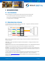
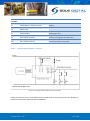
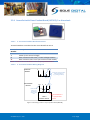
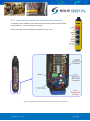
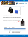
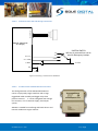
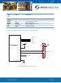
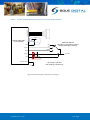
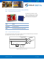
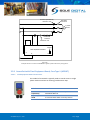
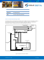
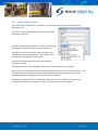
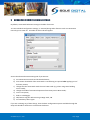
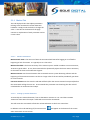
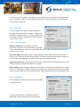
AccessPack Access Control System Model APP10x, Version 2 Installation and User Manual V2.3: 16/02/2015 © CASWA Pty Ltd – 2015 CONTENTS 1 OVERVIEW............................................................................................................................ 4 2 SPECIFICATIONS .................................................................................................................... 5 2.1 Electrical Specifications........................................................................................................... 5 2.1.1 AccessPack Puck ....................................................................................................... 5 2.1.2 Interface Boards ....................................................................................................... 5 2.2 Communication Specifications................................................................................................ 7 2.3 Physical Specifications ............................................................................................................ 7 3 2.3.1 AccessPack Puck ....................................................................................................... 7 2.3.2 Interface Boards ....................................................................................................... 8 INSTALLATION DETAILS ......................................................................................................... 9 3.1 Prior to Installation ................................................................................................................. 9 3.2 Wiring Connections & Diagrams ............................................................................................. 9 3.2.1 AccessPack with Wiring Harness (APP100) ............................................................ 10 3.2.2 AccessPack with Wiring Harness and E-Stop Button (APP101) ............................. 10 3.2.3 AccessPack with Crane Pendant Board (APP102), 10 terminals ............................ 11 3.2.4 AccessPack with Crane Pendant Board (APP102), 3 or 4 terminals....................... 13 3.2.5 AccessPack Pre-installed on an 8 button Crane Pendant ...................................... 14 3.2.6 AccessPack with Vehicle Board (APP103) - 1st/2nd/3rd generation designs ....... 15 3.2.7 AccessPack with Door Board (APP105) .................................................................. 20 3.2.8 AccessPack with Fixed Equipment Board (APP106) ............................................... 21 3.2.9 AccessPack with Fixed Equipment Board, Case Type 1 (APP107) .......................... 22 3.2.10 AccessPack with Fixed Equipment Board, Case Type 2 (APP116) .......................... 23 3.2.11 AccessPack with PC Kit (APP108) ........................................................................... 25 3.2.12 AccessPack with VFD Kit (APP109) ......................................................................... 25 3.3 Note for Installing AccessPack on Critical Equipment .......................................................... 26 4 BASIC COMMISSIONING DETAILS......................................................................................... 27 4.1 Installing and Launching the FSU Application ....................................................................... 27 4.1.1 FSU Program Installation........................................................................................ 27 4.1.2 Installing the FSU Application ................................................................................ 27 4.1.3 Launching the application ...................................................................................... 27 © CASWA Pty Ltd – 2015 2 | Page 4.2 Connecting to the Device ...................................................................................................... 28 4.3 Managing Firmware .............................................................................................................. 28 4.4 Checking the Date and Time ................................................................................................. 31 4.5 Basic Setup ............................................................................................................................ 31 4.5.1 5 Applying Basic Settings........................................................................................... 33 ADVANCED COMMISSIONING DETAILS ................................................................................ 34 5.1.1 Motion Tab ............................................................................................................. 35 5.1.2 Card Tab ................................................................................................................. 36 5.1.3 Signals Tab .............................................................................................................. 36 5.1.4 Maintenance Tab ................................................................................................... 38 5.1.5 Advanced Tab ......................................................................................................... 39 6 DOWNLOADING DATA USING THE FSU ................................................................................ 42 7 ACCESSPACK OPERATION .................................................................................................... 43 7.1 Logging On and Enabling Usage ............................................................................................ 43 7.2 User Initiated Logging Off ..................................................................................................... 44 7.3 Automatic Logging Off .......................................................................................................... 44 7.4 Resetting the Maintenance Interval ..................................................................................... 44 7.5 Electronic Tag Out ................................................................................................................. 44 7.6 Indicator States ..................................................................................................................... 45 8 TROUBLESHOOTING ............................................................................................................ 46 APPENDIX A: COMMUNICATION PROTOCOL ............................................................................... 47 APPENDIX B: FSU SYSTEM REQUIREMENTS ................................................................................. 50 APPENDIX C: FACTORY DEFAULT SETTINGS ................................................................................. 51 © CASWA Pty Ltd – 2015 3 | Page 1 OVERVIEW AccessPack is an access control system that can be fitted to any electrically powered device, including stand-alone, mobile or remote plant. AccessPack uses smart card technology to ensure that equipment can only be used by authorised personnel. Users are automatically logged off when the equipment is stationary, idle or stopped. To ensure accountability, AccessPack records who accessed the equipment and when they did so. An AccessPack device consists of two parts: (a) a generic blue puck that contains the RFID reader and smart electronics, usually mounted on the outside of the equipment to be protected, and (b) a power supply board, specific to the type of equipment being protected, that is typically mounted inside the equipment. Currently AccessPack kits are available for the following applications: Crane joystick radios and pendants Doors Vehicles Fixed equipment (e.g. Break-out machines, lathes, ovens etc) Computer terminals Variable frequency drives The type of AccessPack kit must be specified at time of ordering. © CASWA Pty Ltd – 2015 4 | Page 2 SPECIFICATIONS 2.1 Electrical Specifications 2.1.1 AccessPack Puck Parameter Description Min Vin Iin Start up Button Output Supply voltage Supply current Current Operating temperature 4 6 Typ 7 10 Max Units 12 90* VDC mA mA °C # -40 85 *only when communicating via Bluetooth # Extended operation at maximum temperature will reduce device life. 2.1.2 Interface Boards Note that models for crane radios, APP100 and APP101 do not have an interface board. 2.1.2.1 Crane Pendant Board (APP102) 2.1.2.1.1 Pendant Board with 10 terminals Parameter Description Min Vin Relay Output 1 Relay Output 1 Relay Output 1 Relay Output 2 Relay Output 2 Relay Output 2 Supply voltage Current Voltage Power Current Voltage Power 18 2.1.2.1.2 Typ Max Units 55 500 60 10 500 60 10 VAC mA VAC W mA VAC W Max Units 250 4 250 >100 4 250 >100 VAC A VAC W A VAC W Pendant Board with 4 terminals Parameter Description Min Vin Relay Output 1 Relay Output 1 Relay Output 1 Relay Output 2 Relay Output 2 Relay Output 2 Supply voltage Current Voltage Power Current Voltage Power 18 © CASWA Pty Ltd – 2015 Typ 5 | Page 2.1.2.1.3 Pendant Board with 3 terminals Parameter Description Min Vin Relay Output 1 Relay Output 1 Relay Output 1 Supply voltage Current Voltage Power 18 2.1.2.2 Max Units 250 4 250 >100 VAC A VAC W Vehicle Board (APP103) 2.1.2.2.1 Initial Design (no part number on device) Parameter Description Min Vin Relay Output (NO) Relay Output (NO) Supply voltage Current Voltage 12 2.1.2.2.2 Typ Max Units 24 10 36 VDC A VDC Max Units 48 10 48 VDC A VDC Max Units 48 1 20 48 VDC A VDC 2nd Design (marked as APP103, plastic case) Parameter Description Min Vin Relay Output (NO) Relay Output (NO) Supply voltage Current Voltage 12 2.1.2.2.3 Typ 3rd Generation (also marked as APP103, metal case) Parameter Description Min Vin Relay Output (NO) Relay Output (NO) Supply voltage Current Voltage 6 1 Typ Typ When relay common bridging link is used 2.1.2.3 Door Board (APP105) This board is used in AccessPack LockBoxes (APP105LB, APP105BB). Parameter Description Min Typ Max Units Vin Relay Output Relay Output Supply voltage Current Voltage 8 12 24 8 36 VDC A VDC Typ Max Units 240 8 480 VAC A VAC 2.1.2.4 Fixed Equipment Board (APP106, APP107, APP116) Parameter Description Min Vin Relay Output Relay Output (NO) Supply voltage Current Voltage 32 © CASWA Pty Ltd – 2015 24 6 | Page 2.1.2.5 PC Dongle (APP108) Parameter Description Min Typ Max Units Vin Supply voltage (USB) 4 5 6 VDC 2.2 Communication Specifications Communications between the device and a host is usually via a Bluetooth radio link. The Bluetooth device PIN is 0000. For more details on the communication protocol used to communicate with the AccessPack, see Appendix A. 2.3 Physical Specifications 2.3.1 AccessPack Puck The new AccessPack Puck enclosure is made of glass filled nylon (Tested in accordance to UL94). Prior to May 2012, the enclosure was made from cast epoxy resin. Dimensions of the AccessPack Puck are provided in the following table and diagram. Overall length (mm): 55 Overall width (mm): 50 Overall height (mm): 41 Weight (kg): Mounting: 160g Standard 22 mm hole Figure 1: Dimensions of AccessPack puck © CASWA Pty Ltd – 2015 7 | Page 2.3.2 Interface Boards The overall dimensions of the interface boards and/or their cases are: Model Length (mm) Width (mm) Height (mm) Crane radio APP100, APP101 No board – wiring harness only Crane pendant board (3/4 terminals) APP102 54 40 25 Vehicle board (generation 1 in case) APP103 66 49 36 Vehicle board (generation 2 in case) APP103 107 68 32 Vehicle board (generation 3 in case) APP103 110 120 37 Door board APP104 51 19 11 Fixed equipment board (no case) APP106 89 60 43 Fixed equipment board, Case Type 1 with E-Stop APP107 120 85 103 PC board APP108 65 25 14 Fixed equipment board, Case Type 2 with cable harness APP116 105 74 40 Variable Frequency Drive board APP109 No board – wiring harness only LockBox (entire unit) APP105LB 200 300 200 BlanketBox (entire unit) APP105BB 500 400 210 © CASWA Pty Ltd – 2015 8 | Page 3 INSTALLATION DETAILS 3.1 Prior to Installation Before installing your AccessPack device visually inspect the device and check that: (a) the type of AccessPack mounting kit is appropriate for your application; (b) the case is not damaged and fits together securely; (c) wiring harness is not damaged. 3.2 Wiring Connections & Diagrams The AccessPack puck comes with a multi-core output cable. The generic connections associated with each coloured core are shown in Figure 2. START ENABLE OUT ENABLE IN HEARTBEAT GND 3.6-10V DC Orange Blue Yellow Green Black Red Figure 2: AccessPack Puck Outputs Start: The Start Output provides 1-5 pulses at logon. The Start connection is an open collector and rated to 24V 10mA. Enable OUT: Enables and disables the operation of the equipment. It changes state when a valid card is presented. Enable IN: Monitors the status of the E-Stop/Enable/Seat-Switch etc. Any voltage between 2VDC and 100VDC inclusive will activate this input and cause the AccessPack to log off instantly. Heartbeat: If the equipment the AccessPack is to be installed on has a light or LED that indicates the equipment is functioning (for example, a flashing green LED), the AccessPack heartbeat connection is connected to the terminal that changes level. A range of Application notes have been developed that provide detailed information on how to wire these connections on a variety of specific equipment types/models. These are available for download from www.accesspack.com.au. Generic guidelines for each model type are provided in the following sections. © CASWA Pty Ltd – 2015 9 | Page 3.2.1 AccessPack with Wiring Harness (APP100) This model of AccessPack is used for HBC Micron or ECO radios. AccessPacks need to be factory installed on these devices due to their size and circuit board complexity. Consequently, no wiring diagram is provided. 3.2.2 AccessPack with Wiring Harness and E-Stop Button (APP101) This type of AccessPack is typically installed on HBC joystick radios. 3.2.2.1 Wiring Harness Connections Wire colour Description Black Red Green Orange Yellow Blue Battery –ve Battery +ve (>3.6V) Heartbeat / Flashing LED Start button E-Stop, prewired Not connected These can be connected as per the wiring diagram shown in Figure 3. © CASWA Pty Ltd – 2015 10 | Page Existing E-Stop Wiring Replace Existing E-Stop White Radio Battery Black Red Find the pin that pulses when the LED flashes green Green Yellow Black Orange X Break cable Blue (Not Connected) Start Button Figure 3: Wiring diagram for APP101 3.2.3 AccessPack with Crane Pendant Board (APP102), 10 terminals 3.2.3.1 Pendant Board Connections - 10 inputs 10 9 8 7 6 5 4 3 2 1 This diagram shows the location of terminal 1. © CASWA Pty Ltd – 2015 11 | Page Terminal Number 1 2 3 4 5 6 7 8 9 10 3.2.3.2 Name Description E-Stop Monitor Switch Terminal E-Stop Monitor Switch Terminal 48VAC Input 48VAC Input E-Stop Output E-Stop Output Start Output Terminal Start Output Terminal Horn Output Terminal Horn Output Terminal Connects to second NC contact on E-Stop Button Power Connects in series with E-Stop switch to deactivate crane Replaces start switch so AccessPack can pulse a start signal to activate crane Connect in parallel to the start button to sound horn when crane starts Pendant Wiring Diagram - 10 inputs Figure 4: Connecting an APP102 (Horn outputs not shown) It WILL be necessary to run a new 48VAC neutral conductor from the switch panel to the pendant to provide the AccessPack Interface board with 48VAC. © CASWA Pty Ltd – 2015 12 | Page 3.2.4 AccessPack with Crane Pendant Board (APP102), 3 or 4 terminals 3.2.4.1 3 -4 terminal Pendant Board Connections Terminal numbers are marked on the circuit board from 0 to 3. Terminal Description Number 0 Connects to 0 Volts 1 Power (Crane control voltage) 2 Main contactor hold circuit / control voltage common 3* Main contactor start circuit (not used in normal installs) Note: Terminal 3 is not included on the 3-input pendant board. 3.2.4.2 3 -4 Terminal Pendant Wiring Diagram 1 EXISTING WIRING 2 3 If wired on existing pendant. Otherwise leave out (e.g. Demag pendants). ESTOP ACCESSPACK INSTALL Technician will need to run this voltage down a spare core. 0V START 1 2 3 1 2 3 ESTOP 0 4 INPUT PENDANT BOARD Not included on a 3 input pendant board Figure 5: Connecting a new 3 or 4 input pendant board (APP102) © CASWA Pty Ltd – 2015 13 | Page 3.2.5 AccessPack Pre-installed on an 8 button Crane Pendant To simplify onsite installation, an AccessPack can be factory fitted to a new 8 push button pendant. This is installed as per Figure . Onsite work then involves wiring up the pendant to the crane. Figure 6: AccessPack pendant board installed on a new 8 button crane pendant © CASWA Pty Ltd – 2015 14 | Page 3.2.6 AccessPack with Vehicle Board (APP103) - 1st/2nd/3rd generation designs In 2013, the Vehicle board was revised and enclosed in a new case. This section contains information about using both board designs. The primary difference between the two designs is that the first generation vehicle kit only enabled the engine, whilst the second generation is actually capable of cranking the engine. 3.2.6.1 Original APP103 Board Connections This diagram shows the location of terminal 1, which is indicated by a coloured sleeve (usually white or blue) on the black cable. Cables for connection to vehicle, cable 1 Cable Number Label Description 1 (coloured sleeve) + Ground connection 2 3 4 5 6 © CASWA Pty Ltd – 2015 Enable N/C Com N/O Power connection 8 to 14V Relay Output Terminal Normally Closed Relay Output Terminal Common Relay Output Terminal Normally Open 15 | Page 3.2.6.2 Original APP 103 Wiring Connections VEHICLE INTERFACE 1: - 0V GND 2: + +12V 3: ENABLE 4: N/C 5: COM 6: N/O ENABLE Input (e.g. E-Stop, seat switch, ignition switch etc) Access controlled circuit (e.g. Ignition power relay, fuel solenoid or injection power relay, starter solenoid relay) Figure 7: Connecting an APP103 The enable connection is used to provide a signal to the AccessPack to commence looking for an access card. 3.2.6.3 2nd Generation APP103 Board Connections The second generation of the APP103 Vehicle Board comes in a physically larger ABS box (rather than aluminium) and includes mounting tabs on each side. It's sticker clearly states that it is a APP103 Vehicle Kit (as opposed to the 1st generation design that did not contain these markings). The second generation APP103 vehicle kit can either enable the accessories or crank the engine, depending on how it is connected. Cable Number Label Description 1 2 3 4 5 6 GND 12-48V ACC CRANK ENABLE HEARTBEAT Ground connection Power connection 12-48VDC Relay Output to Start Accessories Relay Output to Start Crank Input to initiate looking for an access card Periodic input to check that access should be maintained © CASWA Pty Ltd – 2015 16 | Page 2nd Generation APP 103 Wiring Connections TO ACCESSPACK 3.2.6.4 APP103: Vehicle Kit (2nd Design) OFF ACC Out 2 ACC IGNITION SWITCH NB: Key is removed but can be used as Emergency backup. CRANK Out 1 CRANK 12-48VDC New E-STOP 12-48 VDC GND 0V GND Figure 8: Connecting a 2nd Generation APP103 Kit 3.2.6.5 3rd Generation APP103 Board Connections The third generation of the APP103 Vehicle Board comes in a physically larger metal box with a large ruggedized cable assembly and bigger relays than previous versions . It can be configured with voltage free contacts, or as a common supply, dual output system. APP103 is suitable for interfacing with both electric and internal combustion engine vehicles. © CASWA Pty Ltd – 2015 17 | Page Cable Colour Label Description Green /Yellow Brown Orange White Red Blue GND Ground connection ACC COM ACC CRANK COM CRANK ENABLE Relay 1 (N/O) (Acc circuit) Relay 1 Common Relay 2 (N/O) (Crank circuit) Relay 2 Common Pull high to disable 3rd Gen APP103 Wiring Connections for Electric Vehicles TO ACCESSPACK 3.2.6.6 12-48V APP103: Vehicle Kit (3rd Generation) Seat Switch Optional E-Stop . Blue Brown Existing Stop or Main Contactor Coil circuit Orange Red 12-48 VDC Green & Yellow 0V GND Figure 9: Example wiring for an electric vehicle © CASWA Pty Ltd – 2015 18 | Page 3rd Gen APP103 Wiring Connections for Vehicles with IC Engines TO ACCESSPACK 3.2.6.7 12-48V APP103: Vehicle Kit (3rd Generation) Seat Switch Optional . Blue OFF ACC Brown IGNITION SWITCH NB: Key is removed but can be used as Emergency backup. CRANK White Orange 12-48 VDC Red New E-STOP Link required if circuit draws more than 10A Green & Yellow 0V GND All wiring in parallel with existing connections. Figure 10: Example wiring for a vehicle with an IC Engine © CASWA Pty Ltd – 2015 19 | Page 3.2.7 AccessPack with Door Board (APP105) 3.2.7.1 Door Board Connections Cable Number 3.2.7.2 Label Details 1 2 GND 12VDC 3 4 Strike + Strike - 0V 9-18VDC with enough current to operate the door strike Output to door strike unit Typical APP105 Wiring Typical wiring for connecting an AccessPack to an electronic door strike is provided in Figure 11. Figure 11: Example of how to connect an APP105 © CASWA Pty Ltd – 2015 20 | Page 3.2.8 AccessPack with Fixed Equipment Board (APP106) 3.2.8.1 Fixed Equipment Board Connections This model of AccessPack is usually used for controlling access to 3-phase contactor started machines or single phase switched circuit equipment. Label Details START N (Neutral) A (Active) STOP 8A 440VAC, Replaces start or power switch 24-240VAC Neutral 24-240VAC Active To second switch block on E-Stop switch 3.2.8.2 Example APP106 Wiring Diagram For a typical 3-phase motor wired as shown in Figure 12, then an example of how you can connect the APP106 model AccessPack is provided in Figure 13. Contacts operated by contactor coil L1 A L2 A L3 STOP Overload Protection 3 phase motor A START Overload Contacts B Contactor Coil Figure 12: Typical 3 phase motor setup © CASWA Pty Ltd – 2015 21 | Page Contacts operated by contactor coil L1 A L2 A L3 A B Overload Protection 3 phase motor Overload Contacts Contactor Coil START STOP Toggle FIXED EQUIPMENT BOARD A N Pulse N Figure 13: Example of how to connect an APP106 to a typical 3-phase machine as per Figure 12. 3.2.9 AccessPack with Fixed Equipment Board, Case Type 1 (APP107) 3.2.9.1 Fixed Equipment Board Connections This model of AccessPack is typically used to control access to single phase machines without an existing push-button E-Stop. © CASWA Pty Ltd – 2015 Label Details START N (Neutral) A (Active) STOP 8A 440VAC, Replaces start or power switch 24-240VAC Neutral 24-240VAC Active To second switch block on E-Stop switch 22 | Page 3.2.9.2 Example APP107 Wiring An example of how a model APP107 AccessPack can be installed on a single phase electric machine is provided in Figure 14. Note that the E-Stop is already prewired to the button on the fixed equipment case. Figure 14: Example of how to wire an APP107. 3.2.10 AccessPack with Fixed Equipment Board, Case Type 2 (APP116) 3.2.10.1 Fixed Equipment (BOM) Board Connections This model of AccessPack is usually used for controlling access to 3-phase contactor started machines or single phase switched circuit equipment with a separate start and E-Stop button. It is a variant of APP106 with an additional prewired emergency stop and enclosed in a case. This is the model typically supplied for Break Out Machines. © CASWA Pty Ltd – 2015 23 | Page Label Details START N (Neutral) A (Active) STOP 8A 440VAC, Replaces start or power switch 24-240VAC Neutral 24-240VAC Active To new E-Stop switch (prewired) 3.2.10.2 Example APP116 Wiring for BOM An example of how a model APP116 AccessPack can be installed in a break out machine (or other 3phase machine with separate start and stop switches) is provided in Figure 15. Note that the replacement E-Stop is already prewired to the cable emanating from the case. Contacts operated by contactor coil L1 A L2 L3 A Overload Contacts NEW E-STOP B To AccessPack puck 3 phase motor A Contactor Coil Prewired N Supplied wiring harness Overload Protection Not connected N A Toggle Pulse START STOP FIXED EQUIPMENT BOARD INSIDE CASE Prewired internally Figure 15: Example of how to wire an APP116. © CASWA Pty Ltd – 2015 24 | Page 3.2.11 AccessPack with PC Kit (APP108) 3.2.11.1 PC Kit Connections The PC Kit fits into a USB slot onto the machine. The other end is connected to the AccessPack, which is mounted where desired. There is no further wiring. To configure the computer to operate using an AccessPack, download and run the AccessPackPC utility, which is available from the AccessPack webpage: www.soledigital.com.au/accesspack.html 3.2.12 AccessPack with VFD Kit (APP109) This AccessPack kit is physically identical to a APP100 kit (AccessPack with wiring harness) used for some types of crane radios. The only difference is that the AccessPack itself may be preconfigured with slightly different timeout settings. However, these can always be altered using the FSU program as described in the following sections of this manual. 3.2.12.1 VFD Kit Connections Wire colour Details Red Black Yellow Orange/Coral Blue Green 4-12V DC Ground E-Stop (Active high) Start (NPN) Not connected Not connected For examples on how to install an AccessPack on different types of variable frequency/speed drive, see the application note: http://www.soledigital.com.au/docs/AccessPack_VFD_control.pdf © CASWA Pty Ltd – 2015 25 | Page 3.3 Note for Installing AccessPack on Critical Equipment Although failure rates on electronic devices such as AccessPack are incredibly low when subjected to normal operating conditions, they are not zero. Severe temperature fluctuations and/or mechanical mishandling further increases the risk of failure. If downtime incurred by an AccessPack failure is absolutely unacceptable, we recommend fitting a key switch (or similar device) in parallel with the AccessPack to allow the protected equipment to be used if/when a problem occurs. The end user should conduct a risk assessment to decide whether this is appropriate for their site. © CASWA Pty Ltd – 2015 26 | Page 4 BASIC COMMISSIONING DETAILS The AccessPack is designed to be commissioned using a laptop computer. You will need a LINK-2 Bluetooth Modem and the Field Service Utility (FSU) software application loaded on a laptop. 4.1 Installing and Launching the FSU Application 4.1.1 FSU Program Installation Ensure that your computer is switched on, connected to the internet and that the minimum required software versions are installed (see Appendix B for minimum system requirements). Ensure that the LINK-2 modem is installed and that the drivers have loaded. 4.1.2 Installing the FSU Application The latest FSU software can be downloaded from http://www.soledigital.com.au/AccessPack.html. You should check this location periodically for updates. 4.1.3 Launching the application Double click on the CASWA FSU program icon: start menu. © CASWA Pty Ltd – 2015 . You’ll find it in the programs folder of your 27 | Page 4.2 Connecting to the Device The FSU will scan for Bluetooth enabled devices. This process takes approximately 10 seconds, when complete a list of all CASWA devices within range will be displayed. AccessPack units are displayed by a icon. If a particular AccessPack unit is not found, ensure it is powered up and press the the search. icon to repeat NB: The Bluetooth link between the Laptop using a Link-2 and an AccessPack has a range of approximately 100m. Select the AccessPack you wish to configure by double clicking on the relevant icon. 4.3 Managing Firmware If you running an older version of the FSU application on your laptop then you should update this before continuing. The process for updating the firmware on your Sole Digital device has changed. Firmware should only be updated if you: a) specifically want a new feature that is only available in later versions; b) are experiencing a problem that has been rectified by a later version; c) are experiencing a problem and need to roll back to an earlier firmware version that didn't cause the problem you are experiencing; or © CASWA Pty Ltd – 2015 28 | Page d) have been specifically instructed to do so by your AccessPack supplier. To check for new firmware versions or to access old firmware versions, return to the Device Display screen and right click the desired equipment icon. Select 'Manage Firmware'. A new window will popup and show the FSU software connecting to the device. When this is complete, the window will show the name of the device, its current firmware version and a list of newer firmware that is available for the device. If you need to roll back to an earlier version, check the 'Show old versions' box in the lower left corner of the window. Select a firmware version and then press the <Apply firmware> button that appears in the lower right corner of the window: © CASWA Pty Ltd – 2015 29 | Page The display will change to the following: As the message states, DO NOT switch off the AccessPack or the computer running the FSU software, or remove the Link2 modem until you are told to do so. If either device loses power then the AccessPack may become unusable and the device will need to be returned to your supplier for repair. When the firmware has finished updating successfully you will see a popup window and also be told to power cycle the device before reconnecting: message in the Close this window, wait for the manage firmware window to close (this may take 20 seconds) and power cycle the device as instructed. You will be returned to the first FSU screen, Manage Connections. Wait a few seconds after power cycling the device and then select the device you wish to connect to by double clicking the device. © CASWA Pty Ltd – 2015 30 | Page 4.4 Checking the Date and Time After selecting the device, the FSU application will automatically verify whether the AccessPack has the same date/time as the computer running the FSU application. If the times are not the same, the following pop up window will display on the screen: Press <Yes> to update the devices date/time or press <No> to leave the date/time on the device as it is. NB: If you did not see this window, then your device has the same date/time as your computer. 4.5 Basic Setup Once firmware versions and date/time has been verified, the following screen will appear. © CASWA Pty Ltd – 2015 31 | Page If the AccessPack is in Basic mode (where any card will activate the device), this setup window will immediately be followed by a warning message: Leave the device in Basic mode if you wish to enable any RFID card to grant access to the controlled device. In this mode only the card serial number is recorded. This is useful when you are first commissioning the device and have not yet programmed cards. Select Enterprise mode to enable the use of the AccessPack Manager to configure permissions to individual devices. You can change the mode at any time through the Card tab (see Advanced Commissioning Details). The ‘Setup’ tab allows you to configure: - The name of the equipment; The location (site) of the equipment; The class of the equipment; NB: This information MUST EXACTLY MATCH the entries for the equipment in the database and is usually provided to you by your equipment vendor. Any changes to these fields will be automatically saved once you exit the field. © CASWA Pty Ltd – 2015 32 | Page 4.5.1 Applying Basic Settings The easiest way to configure an AccessPack is to load a set of basic presets associated with its Equipment Type. To do this, select the appropriate equipment from the 'Set Equipment Type' field: A popup box will appear asking you to confirm that you wish to configure the AccessPack as this type of equipment. Pressing <Yes> will overwrite the existing settings on the AccessPack and close the Popup box. A message box will confirm that the settings have been saved. Alternatively, pressing <No> will close the box without making any changes. The equipment type that was applied will be shown in the Set Equipment Type field. Note: If this field is blank then this AccessPack's settings do not match any current preset file. This may be because the settings were tuned using the Advanced Configuration options or that the standard preset file has changed since the preset was first applied. Changing the settings using the 'Set Equipment Type' presets will not make any changes to the maintenance parameters or binding to a logger. By default these are not enabled. © CASWA Pty Ltd – 2015 33 | Page 5 ADVANCED COMMISSIONING DETAILS By default, AccessPack behaviour settings are hidden from view. To tune individual configuration settings, or activate/change other features such as maintenance intervals, press <CTRL-A>. A number of other tabs will appear: Access the advanced commissioning tabs if you want to: a) set maintenance intervals and lockout behaviour; b) tune motion thresholds if the AccessPack is not behaving as required after applying one of the basic presets; c) change how the AccessPack reads the user's RFID cards (e.g. when using some building access cards); d) change the mode of AccessPack operation from Enterprise to Basic mode; e) save a new preset; f) bind to a datalogger; g) add/remove Tag Out without using a Magic Card; OR h) set mandatory token types. If you are not doing any of these things, then the basic configuration options available through the Setup tab should be sufficient to commission this device. © CASWA Pty Ltd – 2015 34 | Page 5.1.1 Motion Tab This tab displays sliders that adjust parameters relating to the AccessPack’s motion detection hardware. Simply touch the slider to change the value. A text box at the bottom of the page contains an explanation of each parameter and its current value. 5.1.1.1 Motion Parameters Motion Settle Time is the amount of time the AccessPack will wait after logging on or off before beginning to look for motion. It is typically set to a low value. Motion Threshold is the basic sensitivity of the motion system. Smaller numbers are more sensitive; 10-20 are typical values. In use, the AccessPack also dynamically adjusts the basic motion sensitivity to eliminate the chance of inadvertent logouts. Motion Timeout sets the time between the AccessPack motion system detecting stillness and the beginning of the Put Down timeout. Set this to a larger value if the unit will be periodically put down for a few seconds. Put Down Timeout sets the time the red LED will flash (after the motion timeout has expired) before the AccessPack will log the user out. In Door Mode this parameter sets how long the door is held unlocked after an authorised card swipe. 5.1.1.2 Setting up motion detection To manually tune motion detection, first set the Motion Timeout to 1 or 2 and the Put Down Timeout to about 200. The swipe a valid card to activate the AccessPack. This will cause the AccessPack to flash the red LED whenever it thinks it is motionless. In addition to the red LED being off, the motion icon when AccessPack senses motion. © CASWA Pty Ltd – 2015 will appear at the bottom of the screen 35 | Page You can now adjust the Motion Threshold (i.e. the sensitivity of the system) to a level appropriate for the installation. When you are happy with the sensitivity, adjust the Motion Timeout and Put Down Timeout as required. 5.1.2 Card Tab This tab displays sliders that that adjust parameters relating to the AccessPack’s card reader. Simply touch the slider to change the value. A text box at the bottom of the page contains an explanation of each parameter and its current value. 5.1.2.1 Card Parameters RFID Scan Timeout sets the length of time the AccessPack will look for a valid card before returning to an idle state. Setting this value to zero will disable the return to idle and the AccessPack will scan continuously for a card. AccessPack Mode: Select Basic mode to enable any RFID card to grant access to the controlled device. In this mode only the card serial number is recorded. Select Enterprise mode to enable the use of the AccessPack Manager to configure permissions to individual devices. Log Unauthorised Cards: Checking this box will cause the AccessPack to record the names or serial numbers for both accepted and rejected card swipes. Mifare Settings: These settings configure the AccessPack to use only part of the space on the swipe card. This is usually done to allow a customer’s existing access card to be used with the AccessPack system. They should be set to 0 and 160 (as shown) unless directed by the AccessPack Support desk. 5.1.3 Signals Tab This tab displays parameters relating to the AccessPack’s inputs and outputs. A text box at the bottom of the page contains an explanation of the parameter and its current value. © CASWA Pty Ltd – 2015 36 | Page The current status of the AccessPack is also shown. 5.1.3.1 Signals Parameters Heartbeat Timeout: This slider sets the time after detecting a heartbeat signal (a flashing LED, a closed set of contacts etc) that the AccessPack will consider the equipment to have stopped or timed out. After the Heartbeat Timeout has expired, the user is logged out. Simply drag the slider to change the value. Emergency Stop Behaviour: These fields configure how the AccessPack behaves when the Emergency stop signal is detected. Invert Input inverts the polarity of the EStop/Enable input signal. Invert Output inverts the polarity of the EStop/Enable output signal. Sensitivity is the amount of time that the E-Stop input has to be active before this signal is registered. Decrease this if you suspect noise on the E-Stop is causing the AccessPack to log off by dragging the slider to the left. Edge Triggered configures the AccessPack to log out the user only when the E Stop signal transitions from not stopped to stopped. After logging out and disabling the equipment, the AccessPack will immediately start looking for a card. Check this box when the equipment is stationary and has a separate start/stop circuit which will be activated after the user has swiped their card (e.g. Fixed equipment with the AccessPack mounted on the wall). It is recommended that the 'Sensitivity' slider be set to 0 (i.e. Scan indefinitely) and motion sensing disabled when this checkbox is set. © CASWA Pty Ltd – 2015 37 | Page Output Modes: These configure how the outputs behave when a card is presented. In the default mode (no boxes selected) the enable/E-stop is asserted and the start button pulses a number of times as defined by "Start Pushes". Start pushes: Sets the number of times the start output will be pulsed when the AccessPack is activated. When set to > 1, then the sequence is as follows: 600mS pulse. 500mS Pause. 2500mS pulse. 500mS Pause/600mS pulses repeated Alternative output modes are: Pendant Mode: When unchecked, output 1 will toggle high or low to indicate the current locked/unlocked status of the AccessPack. When checked, output 1 will pulse high for one second when a user logs on. This output is used to push a start button. Door Mode: When Door Mode is checked, the Estop output (output 1) will pulse for the duration set by “Put Down Time Out” (This appears in place of "Start Pushes" when Door Mode is first checked). It will also not be possible to bind an AccessPack to a logger (see General Tab) in Door Mode. Crank Mode: When Crank Mode is checked, the Start button is be enabled for as long as a card is held in front of the AccessPack. This is typically used to crank an engine instead of turning a key. 5.1.4 Maintenance Tab The Maintenance tab allows you to view the total operating hours of the equipment. This tab also allows you to set a mandatory Maintenance interval (if desired). When the selected date is reached and the maintenance interval is >0, the AccessPack will either continuously flash both LED’s at the same time to alert the user that the equipment’s maintenance period has expired or lock out the equipment (by declining any access requests after the due date). The AccessPack will remain in the alert/locked state enabled until the maintenance due date is reset. This can be done by changing the date using the FSU © CASWA Pty Ltd – 2015 38 | Page application or by swiping a specially issued recertification card. If using the latter, the <Next Due> date will be set to the current date (date that the recertification card is presented) plus the <maintenance interval>. 5.1.4.1 Run Hours Parameters Add to Bluetooth Name causes the total operating hours to be appended to the Bluetooth name of the device. This allows the run hours to be read with any mobile phone or laptop. Under normal conditions, the run hours will be updated twice a day. Maintenance interval: This slider changes the required periodicity of re-certification or maintenance. If set to zero, alarming or lockout due to overdue certification will NOT be enabled. Next due is the date by which mandatory certification or maintenance must be performed. If blank, alarming or lockout due to overdue certification will NOT be enabled. Lock when due establishes whether, in the event of an overdue certification period, the AccessPack will merely flash to alarm the operators or whether it will actually disable the equipment Note: This option should only be selected following a risk assessment that confirms that there is no possibility for unsafe conditions arising as a result of the equipment being locked out. Tagged Out is checked when the protected machine is not to be used by anyone (e.g. out for maintenance). The AccessPack will flash both LEDs simultaneously to alert operators of this state. This check box can be checked/unchecked by swiping a Tag Out Magic Card. 5.1.5 Advanced Tab 5.1.5.1 Save Settings as a Preset If you have changed the configuration settings from their default values and want to save these as a new type of preset, press the <Save Settings as Preset> button. A new dialog box will appear: Enter the name for this configuration and a brief description. Press <Save>. © CASWA Pty Ltd – 2015 39 | Page A new preset file (*.ap) with the name you have supplied will be saved in the \Documents\FSUPresets\ folder on the laptop being used to configure the AccessPack. It is saved to your specific directory, so will only be visible to your login. If you want other people to use this preset file, copy the *.ap file to copied to their Documents\FSUPresets\ folder. You may have to manually create this folder. To delete the preset, delete the file from that Folder. 5.1.5.2 Bind to a Logger Binding an AccessPack to a Liftlog™ or Liftlog™XL data logger, tells the AccessPack to send card swipe information to that logger so that it can record the operator’s name along with the usage history of the crane. First check that the logger is connected, powered up and configured (commissioned). Refer to the Liftlog™ or LiftlogXL user manuals for how to do this. To begin the binding process, press <Bind to a Logger>. The following screen will appear: Select the desired logger to bind to and press <OK>. If the desired logger is not in the list, check that the logger is power up. Press <Cancel> and repeat the binding process. NB: If the AccessPack is in Door Mode, you will not be able to bind the AccessPack to a logger as the <Bind to a Logger> button will be disabled. To check whether the AccessPack is in Door Mode, click on the <Signals> tab (see Section 4.5). © CASWA Pty Ltd – 2015 40 | Page 5.1.5.3 Defining Required Tokens In its default state, the AccessPack authorises use if a card is presented containing any token that matches either the Equipment, Site or Class listed on the Setup tab. In situations where multiple sets of permissions are required to operate equipment (e.g. A forklift license and a site induction), check the type of tokens that must be present on the card. © CASWA Pty Ltd – 2015 41 | Page 6 DOWNLOADING DATA USING THE FSU The AccessPack can currently store approximately 200 events in its onboard memory. Data can be downloaded from the AccessPack using the FSU application. (This may be required if you do not have a Site Sentinel that automatically uploads the logon history to a secure webpage. ) Refer to section 4.1 for downloading an installing the FSU application. Connect to the desired AccessPack as detailed in 4.2. Select the Usage tab: A list of users who have recently activated the AccessPack will be displayed. Only the most recent 10 records are shown initially. Depending on the model of AccessPack, it may also show the date and time of each access and whether the user’s card was accepted or rejected. The <refresh> button updates the logon list in the event that another operator has logged on while connected to the AccessPack. The <save to file> button commences a dialogue to save the list to a text file on the computer. When the list is long, only first 10 entries are shown and the load all button is activated. Press <load all> to load the remaining entries: A blue progress bar is visible on the bottom of the screen as data is being loaded to indicate how much data has yet to be retrieved. This may take some time depending on the amount of data stored on the device. © CASWA Pty Ltd – 2015 42 | Page 7 ACCESSPACK OPERATION The AccessPack is used by placing specially configured AccessPack cards1 over the card swipe target (“swiping”). Swiping range is limited to approximately 20mm. 7.1 Logging On and Enabling Usage To log on to a piece of equipment fitted with an AccessPack: 1) Press the E-Stop button and keep it depressed. 2) Ensure the equipment is powered up. a. As the AccessPack power is first reconnected both lights will flash briefly and then the green light will flash for several seconds while it searches for a Liftlog logger. b. If the green light flashes followed by the red light flashing slowly, the AccessPack could not find a logger. The AccessPack will continue to flash the green light followed by slowly flashing the red light at regular intervals (about 30 seconds). c. When the green light stops flashing with no slow red flashing, initial communication is complete. 3) Release the E-Stop button. AccessPack will flash the red and green lights alternately indicating that it is ready to read a user card. 4) Swipe a user card by moving card across the face of the AccessPack (see Figure 16). AccessPack will turn the green light on for an authorised card read or turn on the red light for an unauthorised card read. Figure 16: Location to swipe an AccessPack 1 For information on configuring cards using the AccessPack Manager software see the AccessPack Manager User Guide, available from www.soledigital.com.au/accesspack.html. © CASWA Pty Ltd – 2015 43 | Page With an authorised card read, the equipment will be enabled by the AccessPack. The equipment will beep (if a beeper is fitted) and the AccessPack green light will flash slowly to indicate that the equipment is operable. 7.2 User Initiated Logging Off To log off and make the equipment safe: Press the emergency stop button (if fitted) or other usual shutdown device (e.g. Power, ignition, or isolation switch). The current user will be logged off and the equipment made inoperable. After being logged out, the AccessPack must once again be swiped before the equipment can be used. 7.3 Automatic Logging Off The user will also be logged out if one of the following occurs: the equipment has an inactivity timeout. is stationary for a preconfigured period (if motion sensing is enabled), The Stop input is connected to a seat switch, pressure pad or some other sensor. When the AccessPack detects no motion for a configured interval, the red light will flash rapidly for configurable period to warn the user of the impending logout. During this period, moving the AccessPack will reset the timeout period and the operator will remain logged on. After being logged out, the AccessPack must once again be swiped by a valid card before the equipment can be used. 7.4 Resetting the Maintenance Interval If a mandatory inspection interval has expired and the ‘Lock when due’ parameter has been selected (see section 5.1.4 for more information on setting this parameter), then the operator will not be able to activate the AccessPack and enable operation until the inspection/maintenance/calibration has been performed and the maintenance interval reset using either the FSU application, or the 'Maintenance' magic card. Swiping a 'Maintenance' magic card will reset the <Next Due> date (as shown on the Maintenance tab of the FSU application) to the PC's current date plus the < maintenance interval>. 7.5 Electronic Tag Out Swiping the 'Tag Out' card will prevent all users from enabling the AccessPack and hence stop everyone from using the protected machine. To re-enable access to authorised users re-swipe the © CASWA Pty Ltd – 2015 44 | Page same 'Tag Out' card. Alternatively, this feature can be disabled by connecting to the device using the FSU application and disabling the <Tag Out> check box on the Maintenance Tab. 7.6 Indicator States The current state of the AccessPack is indicated by two lights flashing in different ways, as described in the following table. State LED signals Green Flash Rate Notes Red Power up Quick single flash red and green together Looking for Liftlog after power on Medium rate Cannot find Liftlog Slow Check Liftlog for powered up state Idle – logged off Ready to swipe card Alternating flashing Logged on Slow Card Accepted Light on 2 seconds Card Rejected See your AccessPack administrator About to be logged off and logged off (before idle state) Fast Maintenance period expired OR Quick flash red and green together AccessPack tagged out Will flash continuously until maintenance is performed/ tag removed Red light on Green light on Red light flashing Green light flashing Red light off Green light off © CASWA Pty Ltd – 2015 45 | Page 8 TROUBLESHOOTING Fault Cause Fix No lights when power is applied No power to AccessPack Check power output from application board. This should be 5V between RED and BLACK. Lights flash when E-Stop is pushed in and don’t flash when the E-Stop is pulled out E-Stop setting is inverted Change the ‘Invert E-Stop’ setting. Unit rejects all cards Incorrect configuration Check the spelling and capitalisation of the Equipment, Site, and Class settings of the AccessPack. They must match the values on the web site exactly. Battery not charged on a radio remote Charge the battery. AccessPack requires at least 3.3V to operate correctly. AccessPack has been swiped with a Tag Out card. Rectify the equipment fault that initiated the Tag Out. When safe to do so, reswipe the Tag Out card to return the AccessPack to its normal operating mode. Maintenance interval has been exceeded and lockout selected (both LEDs will be flashing). Undertake the required maintenance and then either (a) swipe a Maintenance Card to reset the maintenance period or (b) connect to the AccessPack using the FSU and enter the Next Due date. Unit accepts all cards Unit is in Basic mode Select ‘Enterprise Mode’ on the card tab of the FSU. AccessPack starts equipment and then logs off after a few seconds. Heartbeat timeout is enabled. If it is not being used, set the heartbeat timeout in the FSU to zero (i.e. disabled). Motion timeout settings are incorrect. Try disabling motion logoff by setting putdown timeout to zero. Red LED flashes continuously Insufficient voltage to drive AccessPack. Check battery or power supply from application board (5VDC between black and red) © CASWA Pty Ltd – 2015 46 | Page APPENDIX A: COMMUNICATION PROTOCOL The host sends single character commands to the device to write or query parameters. Each command must be followed by a carriage return <CR>(ASCII 13). Where the command is a query command, no arguments are sent and the device will respond with a single line (except for the “u” and “E” commands) the requested value in ASCI text followed by a <CR>. Where the command is a set command, an argument may be included between the command and the <CR> . Where numbers are sent or received, they are sent as clear text; eg “1234” Where a number represents a load (eg the “o” and “O” commands, and the logged data returned by the “u” command), it is expressed in 100Kg units. Eg 3.5mt would be sent and received as 35. Where a number represents an elapsed time (eg in the logged data returned by the “u” command) it is expressed in 0.1second units. Eg. 35.4 seconds would be sent as 354. Where dates-time values are sent or received, they are sent in the format dd/mm/yy hh:mm . Hours are in 24 hour clock format. Leading zeros must be used. Eg 3/8/07 13:30 is an invalid datetime and should be sent as 03/08/07 13:30 © CASWA Pty Ltd – 2015 47 | Page Communication commands: Command a R/W Read Description AccessPack mode A b Write Read Write AccessPack mode Read button timeout B d Write Read Write button timeout Get debug level D e Write Read Write debug level Read E-Stop mode E Write Write E-Stop mode i Read Read equipment id I l Write Read Write equipment id Read logger Bluetooth id L m Write Read Set logger Bluetooth id Read motion threshold M n Write Read Write motion threshold Read pendant mode N Write Write pendant mode o Read Read motion settle time O p Write Read Write motion settle time Read putdown time out P Write Write putdown timeout q Read Read equipment class Q r Write Read Write equipment class Read RFID scan timeout R s Write Read Write RFID scan timeout Read site id S t Write Read Write site id Read motion timeout T u Write Read Write motion timeout Read local log © CASWA Pty Ltd – 2015 Example Send:a<CR> Rcv:2 Send:A2<CR> Send:b<CR> Rcv:40 Send:A40<CR> Send:d<CR> Rcv:0 Send:A0<CR> Send:e<CR> Rcv:0 Send:E0<CR> Normal E-Stop Send:E1<CR> Inverted E-Stop mode Send:i<CR> Rcv:hoist1 Send:Ihoist1<CR> Send:l Rcv:00:07:80:86:19:47 Send:L00:07:80:86:19:47<CR> Send:m<CR> Rcv:20 Send:M20<CR> Send:n<CR> Rcv: Send:N1<CR> Set to pendant mode Send:N0<CR> Set normal mode Send:o<CR> Rcv:10 Send:O10<CR> Send:p<CR> Rcv:125 Send:P0<CR> put down timeout disabled. Send:P255<CR> Put down timeout 25.5seconds Send:q Rcv:crane Send:Qcrane<CR> Send:r<CR> Rcv:85 Send:R85<CR> Send:s<CR> Rcv:workshop Send:Sworkshop<CR> Send:t<CR> Rcv:20 Send:T20<CR> Send:u0<CR> Rcv:last_user_name Send:u5<CR> Rcv:sixth_user_on_log 48 | Page Command v R/W Read Description Read firmware version number x Read Read Door mode X Write Write Door mode z Read Read local log size Z ? * ! . Write Read Write local log size Read all parameters Reset QA mode Read state of AccessPack Read © CASWA Pty Ltd – 2015 Example Send:v<CR> Rcv:1.3 Send:x<CR> Rcv:0 Send:X0<CR> Door mode disabled Send:X1<CR> Door mode enabled Send:z<CR> Rcv:6 Send:Z6 Sets local log size to 6 (maximum) Send:?<CR> Send:*<CR> Send:!<CR> Send:.<CR> Rcv:E_STOPPED 49 | Page APPENDIX B: FSU SYSTEM REQUIREMENTS The minimum requirements for operating CASWA’s Field Service Utility (FSU) and Link-2 Bluetooth modem are: Laptop computer running Windows XP SP3 or later; One Spare USB port; Microsoft .NET framework 3.5. © CASWA Pty Ltd – 2015 50 | Page APPENDIX C: FACTORY DEFAULT SETTINGS Parameter Motion Timeout 20 Radio without motion sensing 20 Motion Threshold 10 0 10 0 10 0 10 0 Put Down Timeout 10 0 10 0 100 0 10 40 Motion Settle Time 10 10 10 10 10 10 10 10 RFID Scan Timeout 60 250 60 250 60 60 60 0 Button Timeout 40 40 40 0 0 0 40 0 Estop Invert 0 0 0 1 1 1 1 1 Pendant Mode 0 0 0 1 1 0 0 0 Door Mode 0 0 0 0 0 0 0 1 Log Unauthorised Swipes Edge Triggered EStop 0 0 0 0 0 0 0 0 No No No No No No Yes No Reset to 0/160 No change No change No change No change No change No change No change Mifare Start/End block © CASWA Pty Ltd – 2015 Factory Default Radio with motion sensing 20 Pendant without motion sensing 20 Pendant with motion sensing 20 Vehicle Fixed equipment (All Models) Door (including LockBox) 20 20 0 51 | Page