1
Programming Manual
PIM Master™
Passive Intermodulation Analyzer
with Site Master™ Cable &
Antenna Analyzer Option
MW82119B
Anritsu Company
490 Jarvis Drive
Morgan Hill, CA 95037-2809
USA
http://www.anritsu.com
Part Number: 10580-00403
Revision: C
Published: July 2015
Copyright 2012, 2015 Anritsu Company
TRADEMARK ACKNOWLEDGMENTS
PIM Master, Distance-to-PIM, and Site Master are registered trademarks of Anritsu Company.
Acrobat® and Reader® are registered trademarks of Adobe Corporation
Windows® is a registered trademark of Microsoft Corporation.
NOTICE
Anritsu Company has prepared this manual for use by Anritsu Company personnel and customers as a
guide for the proper installation, operation and maintenance of Anritsu Company equipment and
computer programs. The drawings, specifications, and information contained herein are the property of
Anritsu Company, and any unauthorized use or disclosure of these drawings, specifications, and
information is prohibited; they shall not be reproduced, copied, or used in whole or in part as the basis
for manufacture or sale of the equipment or software programs without the prior written consent of
Anritsu Company.
UPDATES
Updates, if any, can be downloaded from the Anritsu Website at:
http://www.anritsu.com
For the latest service and sales contact information in your area, please visit:
http://www.anritsu.com/contact.asp
Safety Symbols
To prevent the risk of personal injury or loss related to equipment malfunction, Anritsu
Company uses the following symbols to indicate safety-related information. For your own
safety, please read the information carefully before operating the equipment.
Symbols Used in Manuals
Danger
This indicates a risk from a very dangerous condition or procedure that
could result in serious injury or death and possible loss related to equipment
malfunction. Follow all precautions and procedures to minimize this risk.
Warning
This indicates a risk from a hazardous condition or procedure that could
result in light-to-severe injury or loss related to equipment malfunction.
Follow all precautions and procedures to minimize this risk.
Caution
This indicates a risk from a hazardous procedure that could result in loss
related to equipment malfunction. Follow all precautions and procedures to
minimize this risk.
Safety Symbols Used on Equipment and in Manuals
The following safety symbols are used inside or on the equipment near operation locations to
provide information about safety items and operation precautions. Ensure that you clearly
understand the meanings of the symbols and take the necessary precautions before operating
the equipment. Some or all of the following five symbols may or may not be used on all
Anritsu equipment. In addition, there may be other labels attached to products that are not
shown in the diagrams in this manual.
This indicates a prohibited operation. The prohibited operation is indicated
symbolically in or near the barred circle.
This indicates a compulsory safety precaution. The required operation is
indicated symbolically in or near the circle.
This indicates a warning or caution. The contents are indicated symbolically
in or near the triangle.
This indicates a note. The contents are described in the box.
These indicate that the marked part should be recycled.
MW82119B PM
PN: 10580-00403 Rev. C
Safety-1
For Safety
Warning
Always refer to the operation manual when working near locations at
which the alert mark, shown on the left, is attached. If the operation,
etc., is performed without heeding the advice in the operation
manual, there is a risk of personal injury. In addition, the equipment
performance may be reduced. Moreover, this alert mark is sometimes
used with other marks and descriptions indicating other dangers.
Warning
When supplying power to this equipment, connect the accessory
3-pin power cord to a 3-pin grounded power outlet. If power is
supplied without grounding the equipment, there is a risk of receiving
a severe or fatal electric shock.
Warning
Caution
This equipment can not be repaired by the operator. Do not attempt to
remove the equipment covers or to disassemble internal
components. Only qualified service technicians with a knowledge of
electrical fire and shock hazards should service this equipment.
There are high-voltage parts in this equipment presenting a risk of
severe injury or fatal electric shock to untrained personnel. In
addition, there is a risk of damage to precision components.
Electrostatic Discharge (ESD) can damage the highly sensitive
circuits in the instrument. ESD is most likely to occur as test devices
are being connected to, or disconnected from, the instrument’s front
and rear panel ports and connectors. You can protect the instrument
and test devices by wearing a static-discharge wristband.
Alternatively, you can ground yourself to discharge any static charge
by touching the outer chassis of the grounded instrument before
touching the instrument’s front and rear panel ports and connectors.
Avoid touching the test port center conductors unless you are
properly grounded and have eliminated the possibility of static
discharge.
Repair of damage that is found to be caused by electrostatic
discharge is not covered under warranty.
Warning
Safety-2
This product is supplied with a rechargeable battery that could
potentially leak hazardous compounds into the environment. These
hazardous compounds present a risk of injury or loss due to
exposure. Anritsu Company recommends removing the battery for
long-term storage of the instrument and storing the battery in a
leak-proof, plastic container. Follow the environmental storage
requirements specified in the product technical data sheet.
PN: 10580-00403 Rev. C
MW82119B PM
Table of Contents
Chapter 1—General Information
1-1
About this Manual . . . . . . . . . . . . . . . . . . . . . . . . . . . . . . . . . . . . . . . . . . . . 1-1
1-2
Introduction . . . . . . . . . . . . . . . . . . . . . . . . . . . . . . . . . . . . . . . . . . . . . . . . . 1-1
1-3
Remote Operation Setup and Interface . . . . . . . . . . . . . . . . . . . . . . . . . . . 1-1
USB Interface Connection and Setup . . . . . . . . . . . . . . . . . . . . . . . . . . 1-1
Ethernet Interface Connection and Setup . . . . . . . . . . . . . . . . . . . . . . . 1-4
Connectivity . . . . . . . . . . . . . . . . . . . . . . . . . . . . . . . . . . . . . . . . . . . . . . 1-5
PIM Master LAN Connections . . . . . . . . . . . . . . . . . . . . . . . . . . . . . . . . 1-5
1-4
Sending SCPI Commands . . . . . . . . . . . . . . . . . . . . . . . . . . . . . . . . . . . . . 1-6
VISA Interactive Control . . . . . . . . . . . . . . . . . . . . . . . . . . . . . . . . . . . . 1-6
USB Connectivity. . . . . . . . . . . . . . . . . . . . . . . . . . . . . . . . . . . . . . . . . . 1-8
Ethernet Connectivity . . . . . . . . . . . . . . . . . . . . . . . . . . . . . . . . . . . . . 1-10
Chapter 2—Programming with SCPI
2-1
Introduction . . . . . . . . . . . . . . . . . . . . . . . . . . . . . . . . . . . . . . . . . . . . . . . . . 2-1
2-2
Introduction to SCPI Programming . . . . . . . . . . . . . . . . . . . . . . . . . . . . . . . 2-1
SCPI Common Commands . . . . . . . . . . . . . . . . . . . . . . . . . . . . . . . . . . 2-2
SCPI Required Commands . . . . . . . . . . . . . . . . . . . . . . . . . . . . . . . . . . 2-2
SCPI Optional Commands . . . . . . . . . . . . . . . . . . . . . . . . . . . . . . . . . . 2-2
2-3
Subsystem Commands. . . . . . . . . . . . . . . . . . . . . . . . . . . . . . . . . . . . . . . . 2-3
Command Names . . . . . . . . . . . . . . . . . . . . . . . . . . . . . . . . . . . . . . . . 2-3
Hierarchical Command Structure . . . . . . . . . . . . . . . . . . . . . . . . . . . . . 2-4
Query Commands . . . . . . . . . . . . . . . . . . . . . . . . . . . . . . . . . . . . . . . . . 2-5
Identifiers . . . . . . . . . . . . . . . . . . . . . . . . . . . . . . . . . . . . . . . . . . . . . . . . 2-6
Data Parameters . . . . . . . . . . . . . . . . . . . . . . . . . . . . . . . . . . . . . . . . . . 2-6
Data Parameter Notations . . . . . . . . . . . . . . . . . . . . . . . . . . . . . . . . . . . 2-7
The following syntax conventions are used for data parameter descriptions in this
manual:Unit Suffixes . . . . . . . . . . . . . . . . . . . . . . . . . . . . . . . . . . . . . . . 2-7
2-4
Notational Conventions. . . . . . . . . . . . . . . . . . . . . . . . . . . . . . . . . . . . . . . . 2-8
2-5
Notational Examples. . . . . . . . . . . . . . . . . . . . . . . . . . . . . . . . . . . . . . . . . . 2-9
Command Terminators . . . . . . . . . . . . . . . . . . . . . . . . . . . . . . . . . . . . . 2-9
2-6
Formatting Conventions . . . . . . . . . . . . . . . . . . . . . . . . . . . . . . . . . . . . . . 2-10
2-7
Parameter Names. . . . . . . . . . . . . . . . . . . . . . . . . . . . . . . . . . . . . . . . . . . 2-11
Chapter 3—All Modes Programming Commands
3-1
:FETCh:GPS Subsystem . . . . . . . . . . . . . . . . . . . . . . . . . . . . . . . . . . . . . . 3-2
Fetch GPS Fix Data. . . . . . . . . . . . . . . . . . . . . . . . . . . . . . . . . . . . . . . . 3-2
3-2
:INSTrument Subsystem. . . . . . . . . . . . . . . . . . . . . . . . . . . . . . . . . . . . . . . 3-3
3-3
:MMEMory Subsystem . . . . . . . . . . . . . . . . . . . . . . . . . . . . . . . . . . . . . . . . 3-5
MW82119B PM
PN: 10580-00403 Rev. C
Contents-1
Table of Contents (Continued)
3-4
[:SENSe]:GPS Subsystem . . . . . . . . . . . . . . . . . . . . . . . . . . . . . . . . . . . . . 3-8
GPS On/Off . . . . . . . . . . . . . . . . . . . . . . . . . . . . . . . . . . . . . . . . . . . . . . 3-8
GPS Reset. . . . . . . . . . . . . . . . . . . . . . . . . . . . . . . . . . . . . . . . . . . . . . . 3-8
GPS Antenna Current . . . . . . . . . . . . . . . . . . . . . . . . . . . . . . . . . . . . . . 3-9
GPS Antenna Voltage . . . . . . . . . . . . . . . . . . . . . . . . . . . . . . . . . . . . . . 3-9
3-5
:SYSTem Subsystem . . . . . . . . . . . . . . . . . . . . . . . . . . . . . . . . . . . . . . . . 3-10
Chapter 4—PIM Analyzer Programming Commands
4-1
SCPI Commands Introduction . . . . . . . . . . . . . . . . . . . . . . . . . . . . . . . . . . 4-1
4-2
:CALCulate Subsystem. . . . . . . . . . . . . . . . . . . . . . . . . . . . . . . . . . . . . . . . 4-2
4-3
:CALibration Subsystem . . . . . . . . . . . . . . . . . . . . . . . . . . . . . . . . . . . . . . 4-17
4-4
:DISPlay Subsystem . . . . . . . . . . . . . . . . . . . . . . . . . . . . . . . . . . . . . . . . . 4-18
4-5
:INITiate Subsystem . . . . . . . . . . . . . . . . . . . . . . . . . . . . . . . . . . . . . . . . . 4-19
4-6
:MMEMory Subsystem . . . . . . . . . . . . . . . . . . . . . . . . . . . . . . . . . . . . . . . 4-20
4-7
:SENSe Subsystem . . . . . . . . . . . . . . . . . . . . . . . . . . . . . . . . . . . . . . . . . 4-23
4-8
:TRACe Subsystem . . . . . . . . . . . . . . . . . . . . . . . . . . . . . . . . . . . . . . . . . 4-36
Chapter 5—Cable & Antenna Commands
5-1
:CALCulate Subsystem. . . . . . . . . . . . . . . . . . . . . . . . . . . . . . . . . . . . . . . . 5-1
5-2
:CALibration Subsystem . . . . . . . . . . . . . . . . . . . . . . . . . . . . . . . . . . . . . . 5-11
5-3
:CONFigure Subsystem . . . . . . . . . . . . . . . . . . . . . . . . . . . . . . . . . . . . . . 5-12
5-4
:DISPlay Subsystem . . . . . . . . . . . . . . . . . . . . . . . . . . . . . . . . . . . . . . . . . 5-14
5-5
:FORMat Subsystem. . . . . . . . . . . . . . . . . . . . . . . . . . . . . . . . . . . . . . . . . 5-16
Interpreting Returned Data Pair. . . . . . . . . . . . . . . . . . . . . . . . . . . . . . 5-17
5-6
:INITiate Subsystem . . . . . . . . . . . . . . . . . . . . . . . . . . . . . . . . . . . . . . . . . 5-19
5-7
:MMEMory Subsystem . . . . . . . . . . . . . . . . . . . . . . . . . . . . . . . . . . . . . . . 5-21
5-8
:TRACe Subsystem . . . . . . . . . . . . . . . . . . . . . . . . . . . . . . . . . . . . . . . . . 5-24
5-9
[:SENSe] Subsystem . . . . . . . . . . . . . . . . . . . . . . . . . . . . . . . . . . . . . . . . 5-25
Appendix A—Examples
A-1
C/C++ . . . . . . . . . . . . . . . . . . . . . . . . . . . . . . . . . . . . . . . . . . . . . . . . . . . . . A-1
A-2
Visual Basic . . . . . . . . . . . . . . . . . . . . . . . . . . . . . . . . . . . . . . . . . . . . . . . . A-5
A-3
Visual Basic . . . . . . . . . . . . . . . . . . . . . . . . . . . . . . . . . . . . . . . . . . . . . . . . A-7
A-4
Visual Basic . . . . . . . . . . . . . . . . . . . . . . . . . . . . . . . . . . . . . . . . . . . . . . . A-12
A-5
LabVIEW™ . . . . . . . . . . . . . . . . . . . . . . . . . . . . . . . . . . . . . . . . . . . . . . . . A-15
Appendix B—PIM Carrier Bands
B-1
Introduction . . . . . . . . . . . . . . . . . . . . . . . . . . . . . . . . . . . . . . . . . . . . . . . . . B-1
B-2
PIM Master Carrier Bands
Contents-2
. . . . . . . . . . . . . . . . . . . . . . . . . . . . . . . . . . . B-2
PN: 10580-00403 Rev. C
MW82119B PM
Appendix C—List of Commands by Mode
Appendix D—List of Commands, Alphabetical
MW82119B PM
PN: 10580-00403 Rev. C
Contents-3
Contents-4
PN: 10580-00403 Rev. C
MW82119B PM
Chapter 1 — General Information
1-1
About this Manual
This SCPI Programming Manual provides information for remote operation of the
PIM Master MW82119B, Passive Intermodulation (PIM) Analyzer, using commands sent
from an external controller through the USB or Ethernet connection.
This Programming Manual includes the following:
• An overview of the USB and Ethernet connections to the instrument.
• An overview of Standard Commands for Programmable Instruments (SCPI) command
structure and conventions.
• The IEEE common commands that are supported by the instruments.
• A complete listing and description of all the SCPI commands that can be used to
remotely control functions of the instrument. The commands are organized by
measurement mode starting in Chapter 3, “All Modes Programming Commands”.
This manual is intended to be used in conjunction with the PIM Master MW82119B User
Guide. Refer to the instrument user guide for general information about the instrument,
including equipment setup and operating instructions.
1-2
Introduction
This chapter provides a general description of remote programming setup and interface using
USB or Ethernet, and sending SCPI commands to the instrument.
1-3
Remote Operation Setup and Interface
Remote operation of the instrument is accomplished via the USB or Ethernet interface. The
following paragraphs provide information about the interface connections, cable
requirements, and setting up remote operation.
USB Interface Connection and Setup
The Universal Serial Bus (USB) architecture is a high-performance networking standard that
is considered “plug and play” compatible. The USB driver software is automatically detected
and configured by the operating system of the devices that are connected to the bus. The
instrument conforms to the USB 2.0 standard and is a USB “Hi-speed” device that supports
data rates of up to 480 Mbps with the following restrictions:
• One USB network can support up to 127 devices
• The maximum length of USB cables between active devices is 5 meters (for USB 2.0)
and 3 meters (for USB 1.0)
You must have NI-VISA 2.5 or later installed on the controller PC and must select the VISA
library (visa32.dll) as a reference in a Visual Basic project. For remote USB control, the
controlling PC needs to have a version of VISA installed that supports USBTMC (USB Test
and Measurement Class) devices.
MW82119B PM
PN: 10580-00403 Rev. C
1-1
1-3
Remote Operation Setup and Interface
Chapter 1 — General Information
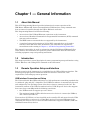
USB Interface, Type Mini-B
The USB 2.0 Mini-B device connector is used to connect the instrument directly to a
PC. The first time the instrument is connected to a PC, the normal USB device
detection by the computer operating system takes place.
1. Power on the instrument and controller PC and wait for the systems to power up
completely.
2. Connect the USB cable Mini-B connector to the instrument.
3. Connect the USB cable A connector to the controller PC USB host port. The
controller PC should indicate “New Hardware Found” if the combination of USB
VID/PID/Serial Number has never been connected to this controller PC.
Figure 1-1.
1-2
USB Found New Hardware Wizard
PN: 10580-00403 Rev. C
MW82119B PM
Chapter 1 — General Information
1-3
Remote Operation Setup and Interface
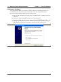
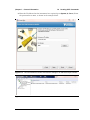
4. Select to allow the Wizard to search for and install the USB software
automatically.
Figure 1-2.
USB Found New Hardware Wizard
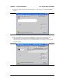
5. After the software installs, close the Wizard by clicking Finish.
Figure 1-3.
USB Found New Hardware Wizard
MW82119B PM
PN: 10580-00403 Rev. C
1-3
1-3
Remote Operation Setup and Interface
Chapter 1 — General Information
Ethernet Interface Connection and Setup
The PIM Master MW82119B fully supports the IEEE-802.3 standard. Most PIM Master
functions (except power On/Off) can be controlled via an Ethernet connection to a PC that is
connected directly (with an Ethernet cross-over cable) or through a network.
Ethernet networking uses a bus or star topology in which all of the interfacing devices are
connected to a central cable called the bus, or are connected to a hub. Ethernet uses the
CSMA/CD access method to handle simultaneous transmissions over the bus. CSMA/CD
stands for Carrier Sense Multiple Access/Collision Detection. This standard enables network
devices to detect simultaneous data channel usage (called a collision) and provides for a
contention protocol. When a network device detects a collision, the CSMA/CD standard
dictates that the data is retransmitted after waiting a random amount of time. If a second
collision is detected, then the data are again retransmitted after waiting twice as long. This is
known as exponential back off.
The TCP/IP setup requires the following:
• IP Address: Every computer/electronic device in a TCP/IP network requires an IP
address. An IP address has four numbers (each between 0 and 255) separated by
periods. For example: 128.111.122.42 is a valid IP address.
• Subnet Mask: The subnet mask distinguishes the portion of the IP address that is the
network ID from the portion that is the station ID. The subnet mask 255.255.0.0, when
applied to the IP address given above, would identify the network ID as 128.111 and
the station ID as 122.42. All stations in the same local area network should have the
same network ID, but different station IDs.
• Default Gateway: A TCP/IP network can have a gateway to communicate beyond the
LAN that is identified by the network ID. A gateway is a computer or electronic device
that is connected to two different networks and can move TCP/IP data from one
network to the other. A single LAN that is not connected to other LANs requires a
default gateway setting of 0.0.0.0. If you have a gateway, then the default gateway
would be set to the appropriate value of your gateway.
• Ethernet Address: An Ethernet address (also known as a MAC address) is a unique
48-bit value that identifies a network interface card to the rest of the network. Every
network card has a unique ethernet address permanently stored into its memory.
1-4
PN: 10580-00403 Rev. C
MW82119B PM
Chapter 1 — General Information
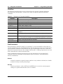
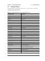
Table 1-1.
1-3
Remote Operation Setup and Interface
8-pin Ethernet RJ45 Connector Pinout Diagram
87654321
Pin
Name
Description
Wire Color
1
TX+
Transmit data (> +3 volts)
White/Orange
2
TX–
Transmit data (< –3 volts)
Orange
3
RX+
Receive data (> +3 volts)
White/Green
4
—
Not used (common mode termination)
Blue
5
—
Not used (common mode termination)
White/Blue
6
RX–
Receive data (< –3 volts)
Green
7
—
Not used (common mode termination)
White/Brown
8
—
Not used (common mode termination)
Brown
Connectivity
TCP/IP connectivity requires setting up the parameters that are described at the beginning of
this section. The following is a brief overview of how to set up a general LAN connection on
the PIM Master.
Note
You may need to consult your network documentation or network administrator for
assistance in configuring your network setup.
PIM Master LAN Connections
The RJ-45 connector is used to connect the PIM Master to a local area network (LAN).
Integrated into this connector are two LEDs. The amber LED (Light Emitting Diode)
indicates the speed of the LAN connection (ON for 100 Mb/s and OFF for 10 Mb/s), and the
green LED flashes to show that LAN traffic is present. The instrument IP address is set
automatically by using Dynamic Host Configuration Protocol (DHCP). DHCP is an Internet
protocol that automates the process of setting IP addresses for devices that use TCP/IP, and is
the most common method of configuring a device for network use. After the Ethernet cable is
connected to the instrument, go to System, then Status (key sequence: Shift > System (9) >
Status) to view the IP address that the instrument has been assigned.
MW82119B PM
PN: 10580-00403 Rev. C
1-5
1-4
Sending SCPI Commands
1-4
Chapter 1 — General Information
Sending SCPI Commands
SCPI commands can be sent to the instrument through any Virtual Instrument Software
Architecture (VISA) controller. VISA is a commonly used API in the Test and Measurement
industry for communicating with instruments from a PC. The physical connection between
the PC and the instrument is USB or Ethernet. NI-VISA is the National Instruments
implementation of the VISA I/O standard. Information and downloads are available at:
http://www.ni.com/visa/
The following examples describe the verification that a VISA controller can interact with the
instrument. The images shown and the instructions for your instrument and software may
differ from the examples.
Note
Before remote operation, confirm that the instrument is not in the Menu screen.
Sending commands while the Menu screen is displayed is an invalid operation.
See your User Guide regarding the Menu screen.
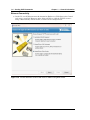
VISA Interactive Control
1. On the PC, run VISA Interactive Control and double-click on the instrument.
Figure 1-4.
1-6
VISA Interactive Control
PN: 10580-00403 Rev. C
MW82119B PM
Chapter 1 — General Information
1-4
Sending SCPI Commands
2. Select the viWrite tab and execute the default *IDN? write by clicking the Execute
button.
Figure 1-5.
VISA Interactive Control viWrite Tab
3. Select the viRead tab and click the Execute button. If the PC is connected to the
instrument the command returns the following information from the Buffer:
manufacturer name (“Anritsu”), model number/options, serial number, and firmware
package number.
Figure 1-6.
VISA Interactive Control viRead Tab
MW82119B PM
PN: 10580-00403 Rev. C
1-7
1-4
Sending SCPI Commands
Chapter 1 — General Information
USB Connectivity
1. On the PC, run NI Measurement & Automation Explorer or VISA Interactive Control
and double-click on the TMC Class instrument.
Figure 1-7.
Figure 1-4. NI Measurement & Automation Explorer
2. Verify that the USB Settings list the correct Manufacturer, Model, and Serial Number,
as shown in the example below.
Figure 1-8.
NI VISA Interactive Control USB Configurations / Settings Tab.
3. Select the Input/Output, Basic I/O tab and execute the default *IDN? Query. If the PC is
connected to the instrument, then the command returns the following information from
1-8
PN: 10580-00403 Rev. C
MW82119B PM
Chapter 1 — General Information
1-4
Sending SCPI Commands
the Buffer: manufacturer name (“Anritsu”), model number/options, serial number, and
firmware package number, as shown in the example below.
Figure 1-9.
NI VISA Interactive Control USB Basic I/O Tab.
MW82119B PM
PN: 10580-00403 Rev. C
1-9
1-4
Sending SCPI Commands
Chapter 1 — General Information
Ethernet Connectivity
1. On the PC, run NI Measurement & Automation Explorer or VISA Interactive Control
and create a new LAN Resource under Network Devices. Add the TCP/IP resource
using a Manual Entry of Raw Socket, as shown in the example below.
Figure 1-10. NI VISA Interactive Control LAN resource addition using Raw Socket.
1-10
PN: 10580-00403 Rev. C
MW82119B PM
Chapter 1 — General Information
1-4
Sending SCPI Commands
2. Enter the IP address that the instrument has acquired (go to System (9), Status). Enter
the port number as 9001, as shown in the example below.
Figure 1-11. NI VISA Interactive Control LAN resource settings of IP address and port number.
Figure 1-12. NI VISA Interactive Control LAN resource validated.
MW82119B PM
PN: 10580-00403 Rev. C
1-11
1-4
Sending SCPI Commands
Chapter 1 — General Information
3. Select the Configuration I/O settings tab and verify that the Termination Methods are
set as shown in the example below.
Figure 1-13. NI VISA Interactive Control LAN resource I/O Termination Method Settings
4. Select the Input/Output Basic I/O tab and execute the default *IDN? Query. If the PC is
connected to the instrument, then the command returns the following information from
1-12
PN: 10580-00403 Rev. C
MW82119B PM
Chapter 1 — General Information
1-4
Sending SCPI Commands
the Buffer: manufacturer name (“Anritsu”), model number/options, serial number, and
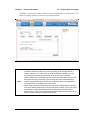
firmware package number, as shown in the example below.
Figure 1-14. NI VISA Interactive Control USB Basic I/O Tab.
When sending SCPI commands over Ethernet, you are required to send a newline
termination character at the end of each command. In the example above, a
newline character ("\n" in this case, but could be different depending on your
programming environment) was used to terminate the *IDN? command.
Note
When sending query commands over raw socket, the entire buffer must be read
before the next query command is sent. Each query result is terminated by a
newline to help identify the end of the query response. Query read operations
could be broken into multiple reads, if necessary.
When using raw socket connections, you must close a session before opening a
new one or before switching to a new protocol (such as USB). If you try to open a
new session or switch protocols without first closing the previously opened
session, then you may lose communications with the instrument and may not be
able to reconnect until you reboot the instrument.
MW82119B PM
PN: 10580-00403 Rev. C
1-13
1-4
1-14
Sending SCPI Commands
Chapter 1 — General Information
PN: 10580-00403 Rev. C
MW82119B PM
Chapter 2 — Programming with SCPI
2-1
Introduction
This chapter provides an introduction to Standard Commands for Programming Instruments
(SCPI) programming that includes descriptions of the command types, hierarchical command
structure, command subsystems, data parameters, and notational conventions.
2-2
Introduction to SCPI Programming
Anritsu instruments can be operated with the use of SCPI commands. SCPI is intended to
give the user a consistent environment for program development. It does so by defining
controller messages, instrument responses, and message formats for all SCPI compatible
instruments. SCPI commands are messages to the instrument to perform specific tasks. The
command set includes:
• “SCPI Common Commands” on page 2-2
• “SCPI Required Commands” on page 2-2
• “SCPI Optional Commands” on page 2-2
Note
The PIM Master follows the SCPI standard, but is not fully compliant with that
standard. The main reason that the PIM Master is not fully compliant is because it
does not support all of the required SCPI commands, and because it uses some
exceptions in the use of short form and long form command syntax.
MW82119B PM
PN: 10580-00403 Rev. C
2-1
2-2
Introduction to SCPI Programming
Chapter 2 — Programming with SCPI
SCPI Common Commands
Some common commands are defined in the IEEE-488.2 standard and must be implemented
by all SCPI compatible instruments. These commands are identified by the asterisk (*) at the
beginning of the command keyword. These commands are defined to control instrument
status registers, status reporting, synchronization, and other common functions. For
example, *IDN? is a common command supported by the PIM Master.
SCPI Required Commands
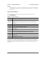
The required SCPI commands supported by the instrument are listed in the Table 2-1.
Table 2-1.
SCPI Required Commands
:STATus
:SYSTem
SCPI Optional Commands
Table 2-2 lists the optional SCPI commands that comprise the majority of the command set
described in this document. These commands control most of the programmable functions of
the instrument.
Table 2-2.
SCPI Optional Commands
:ABORt
:FETCh
:MEASure
:TRACe
:CALCulate
:FORMat
:MMEMory
:TRIGger
:CALibration
:INITiate
:READ
:UNIT
:CONFigure
:INPut
:SENSe
:[SENSe]
:DISPlay
:INSTrument
:SOURce
The SCPI optional commands are sorted by measurement modes, and commands may be
repeated in more than one mode.
• Chapter 3, “All Modes Programming Commands”
• Chapter 4, “PIM Analyzer Programming Commands”
• Chapter 5, “Cable & Antenna Commands”
2-2
PN: 10580-00403 Rev. C
MW82119B PM
Chapter 2 — Programming with SCPI
2-3
2-3
Subsystem Commands
Subsystem Commands
Subsystem commands control all instrument functions and some general purpose functions.
All subsystem commands are identified by the colon used between keywords, as in
:INITiate:CONTinuous.
The following information is provided for each subsystem command described in the following
chapters.
• The command name, refer to “Command Names” on page 2-3.
• The path from the subsystem root command, refer to “Hierarchical Command
Structure” on page 2-4.
• The query form of the command (if applicable), refer to “Query Commands” on page 2-5.
• A description of the purpose of the command.
• The data parameters that are used as arguments for the command, refer to “Data
Parameters” on page 2-6. This may include the parameter type and the available
parameter choices.
Command Names
Typical SCPI commands consist of one or more keywords, parameters, and punctuation. SCPI
command keywords can be a mixture of upper and lower case characters. Except for common
commands, each keyword has a long and a short form. In this manual, the long form is
presented with the short form in upper case and the remainder in lower case. For example,
the long form of the command keyword to control the instrument display is :DISPlay.
The short form keyword is usually the first four characters of the long form (example: DISP
for DISPlay). The exception to this is when the long form is longer than four characters and
the fourth character is a vowel. In such cases, the vowel is dropped and the short form
becomes the first three characters of the long form. Example: the short form of the keyword
:POWer is :POW.
Some command keywords may have a numeric suffix to differentiate between multiple
instrument features such as multiple trace options. For example,
:CALCulate#:DATA? FDATa|SDATa|FMEM|SMEM can result in two different commands, one
for trace 1 ":CALC1:DATA? FDATa" and another for trace 2 ":CALC2:DATA? FMEM".
Note
If a numeric suffix is not included in a command, the first option is implied. Curly
brackets { } designate optional keyword or command parameters. Square brackets
[ ] designate optional command keywords. For example, the command
:TRACe[:DATA]? {1|2} can be sent as :TRACe? or :TRACe? 1, or as
:TRAC? or :TRAC? 1 to obtain data from trace 1.
As with any programming language, the exact command keywords and command syntax
must be used. The syntax of the individual commands is described in detail in the
programming command chapters. Unrecognized versions of long form or short form
commands, or improper syntax, will generate an error.
MW82119B PM
PN: 10580-00403 Rev. C
2-3
2-3
Subsystem Commands
Chapter 2 — Programming with SCPI
Long Format vs. Short Format
Each keyword has a long format and a short format. The start frequency can be specified by
:SENSe:FREQuency:STARt or :SENS:FREQ:STAR. The capital letters in the command
specification indicate the short form of the command. A mixture of the entire short form
elements with entire long form elements of each command is acceptable. For example,
:SENS:FREQuency:STAR is an acceptable form of the command. However,
:SENS:FREQuen:STA is not an acceptable form of the command because :FREQuen is not the
entire short or long form of the command element.
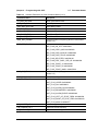
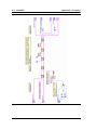
Hierarchical Command Structure
All SCPI commands, except the common commands, are organized in a hierarchical structure
similar to the inverted tree file structure used in most computers. The SCPI standard refers
to this structure as “the Command Tree.” The command keywords that correspond to the
major instrument control functions are located at the top of the command tree. The root
command keywords for the SCPI command set are shown in Figure 2-1.
root
:ABORt
:FETCh
:MEASure
:STATus
:UNIT
:CALCulate
:FORMat
:MMEMory
:SYSTem
[:SENSe]
:CALibration
:INITiate
:READ
:TRACe
:CONFigure
:INPut
:SENSe
:TRIGger
:DISPlay
:INSTrument
:SOURce
Figure 2-1.
SCPI Command Tree
All instrument SCPI commands, except the :ABORt command, have one or more
subcommands (keywords) associated with them to further define the instrument function to
be controlled. The subcommand keywords may also have one or more associated
subcommands (keywords). Each subcommand level adds another layer to the command tree.
The command keyword and its associated subcommand keywords form a portion of the
command tree called a command subsystem. The :CONFigure command subsystem is
shown in Figure 2-2.
2-4
PN: 10580-00403 Rev. C
MW82119B PM
Chapter 2 — Programming with SCPI
2-3
Subsystem Commands
:CONFigure
:ACPower
:OBWidth
:CHPower
:OTA
:DEMOD
:Pfail
:FSTRength
:PM
:MEASure
:PVTFrame
:MENU
:PVTSlot
:S11
:RF
:1PHASEe
:SPECTRUM
:SMCHart
:MULTi
:SINGle
:VSWR
:SUMMARY
:VNA
Figure 2-2.
SCPI :CONFigure Subsystem
A colon (:) separates each subsystem. For example, the command
:SENSe:FREQuency:STARt <freq> sets the start frequency. The start frequency is part of
the :FREQuency subsystem which is part of the :SENSe subsystem. Stop frequency is also
part of the :SENSe:FREQuency subsystem. It is specified by :SENSe:FREQuency:STOP.
Query Commands
All commands, unless specifically noted in the commands syntax descriptions, have a query
form. As defined in IEEE-488.2, a query is a command with a question mark symbol
appended (examples: *IDN? and :OPTions?). When a query form of a command is received,
the current setting associated with the command is placed in the output buffer. Query
commands always return the short form of the parameter unless otherwise specified. Boolean
values are returned as 1 or 0, even when they can be set as on or off.
MW82119B PM
PN: 10580-00403 Rev. C
2-5
2-3
Subsystem Commands
Chapter 2 — Programming with SCPI
Identifiers
The following identifiers have been used throughout the optional command definitions.
Descriptions are provided here. In most cases, units are specified with the individual
command.
Table 2-3.
Description of Command Identifiers
Identifier
Description
<amplitude>
Amplitude value. Units specified with the command.
<freq>
Frequency. Units specified with the command.
<integer>
Integer value, no units. Range specified with the command.
<number>
Numeric value, integer, or real.
<percentage>
Percentage value from 0 to 00. Units are always %.
<rel ampl>
Relative amplitude. Units are always dB.
<x-parameter>
Parameter value in the units of the x-axis. Units are specified with the
command.
<string>
The string should be enclosed in either single quotes (‘ ’) or double quotes
(“ ”).
<file name>
The name should be enclosed in either single quotes (‘ ’) or double quotes
(“ ”). The need for an extension is documented with applicable commands.
<voltage>
Voltage. Units specified with the command.
<current>
Current. Units specified with the command.
Data Parameters
Data parameters, referred to simply as “parameters”, are the quantitative values that are
used as arguments for the command keywords. The parameter type that is associated with a
particular SCPI command is determined by the type of information required to control the
particular instrument function. For example, Boolean (ON | OFF) type parameters are used
with commands that control switch functions.
Some command descriptions specify the type of data parameter to be used with each
command. The most commonly used parameter types are numeric, extended numeric,
discrete, and Boolean.
Numeric
Numeric parameters comprise integer numbers or any number in decimal or scientific
notation, and may include polarity signs.
Discrete
Discrete parameters, such as INTernal and EXTernal, are used to control program
settings to a predetermined finite value or condition.
2-6
PN: 10580-00403 Rev. C
MW82119B PM
Chapter 2 — Programming with SCPI
2-3
Subsystem Commands
Boolean
Boolean parameters represent binary conditions and may be expressed as ON, OFF or
1, 0. Boolean parameters are always returned by query commands as 1 or 0 in numeric
value format.
Data Parameter Notations
The following syntax conventions are used for data parameter descriptions in this
manual:Unit Suffixes
Table 2-4.
Parameter Notations
<arg>
<bNR1>
::=a generic command argument consisting of one or more of the other data types
::=boolean values in <NR1> format; numeric 1 or 0
<boolean>
::=ON | OFF. Can also be represented as 1 or 0, where 1 means ON and 0 means
OFF
Boolean parameters are always returned as 1 or 0 in <NR1> format by query
commands
<integer>
::=an unsigned integer without a decimal point (implied radix point)
<NR1>
::=a signed integer without a decimal point (implied radix point)
<NR2>
::=a signed number with an explicit radix point
<NR3>
::=a scaled explicit decimal point numeric value with and exponent (e.g., floating
point number)
<NRf>
::=<NR1>|<NR2>|<NR3>
<nv>
::=SCPI numeric value: <NRf>|MINimum|MAXimum|UP|DOWN|DEFault|NAN
(Not A Number)|INFinity|NINFinity (Negative Infinity) or other types
<char>
::=<CHARACTER PROGRAM DATA> Examples: CW, FIXed, UP, and DOWN
<string>
::=<STRING PROGRAM DATA> ASCII characters enclosed by double quotes For
example: “OFF”
<block>
::=IEEE-488.2 block data format
<NA>
::=Not Applicable
Unit suffixes are not required for data parameters, provided the values are scaled for the
global default units. The instrument SCPI default units are: Hz (Hertz) for frequency-related
parameters, s (seconds) for time-related parameters, and m (meters) for distance-related
parameters.
MW82119B PM
PN: 10580-00403 Rev. C
2-7
2-4
Notational Conventions
2-4
Chapter 2 — Programming with SCPI
Notational Conventions
The SCPI interface standardizes command syntax and style that simplifies the task of
programming across a wide range of instrumentation. As with any programming language,
the exact command keywords and command syntax must be used. Unrecognized commands
or improper syntax will not function.
Table 2-5.
Notational Conventions
:
A colon links command keywords together to form commands. The colon is not an actual
part of the keyword, but is a signal to the SCPI interface parser. A colon must precede a
root keyword immediately following a semicolon (see “Notational Examples”
on page 2-9).
;
A semicolon separates commands if multiple commands are placed on a single program
line.
[]
Square brackets enclose one or more optional keywords.
{}
Braces enclose one or more keyword or command parameters that may be included
zero or more times.
|
A vertical bar indicates “or” and is used to separate alternative parameter options.
Example: ON | OFF is the same as ON or OFF.
<>
Angle brackets enclose parameter descriptions.
::=
Means “is defined as” For example: <a>::=<b><c> indicates that <b><c> can replace
<a>.
sp
Space, referred to as white space, must be used to separate keywords from their
associated data parameters. It must not be used between keywords or inside keywords.
xxx
Indicates a root command name
#
Indicates an integer value selection from a range of values
For further information about SCPI command syntax and style, refer to the Standard
Commands for Programmable Instruments (SCPI) 1999.0 document.
2-8
PN: 10580-00403 Rev. C
MW82119B PM
Chapter 2 — Programming with SCPI
2-5
2-5
Notational Examples
Notational Examples
Table 2-6 provides examples of valid command syntax:
Table 2-6.
Creating Valid Commands
Command Specification
[:SENSe]:FREQuency:STARt
<frequency>{Hz|kHz|MHz|GHz}
Valid Forms
The following all produce the same result:
:SENSe:FREQuency:STARt 1 MHZ
:SENS:FREQ:STAR 1 MHZ
:sense:frequency:start 1000000
:FREQ:STAR 1000 KHZ
:CALCulate:MARKer#:X
<value>{Hz|kHz|MHz|GHz,m|cm|mm,ft}
The first 2 commands set the location of
marker 1. The third command sets the location
of marker 2.
:CALC:MARK:X 1 GHZ
:CALC:MARK1:X 1 GHZ
:CALC:MARK2:X 2 GHZ
:INITiate:CONTinuous OFF|ON|0|1
The following commands are identical:
:INITiate:CONTinuous OFF
:init:cont 0
Command statements read from left to right and from top to bottom. In the command
statement above, the :FREQuency keyword immediately follows the :SENSe keyword with
no separating space. A space (sp) is used between the command string and its argument.
Note that the first keyword in the command string does not require a leading colon; however,
it is good practice to always use a leading colon for all keywords. Note also that the :SENSe
keyword is optional. This is a SCPI convention for all voltage or signal source type
instruments that allows shorter command statements to be used.
The following is an example of a multiple command statement that uses two separate
commands in a single statement:
:FREQuency:STARt 10E6;:FREQuency:STOP 20E9
Note
A semicolon is used to join the commands and a leading colon used immediately
after the semicolon to start the second command.
Command Terminators
The <new line> character (ASCII 10) in the last data byte of a command string is used as a
command terminator. Use of a command terminator resets the command path to the root of
the tree.
MW82119B PM
PN: 10580-00403 Rev. C
2-9
2-6
2-6
Formatting Conventions
Chapter 2 — Programming with SCPI
Formatting Conventions
This manual uses the conventions listed below in describing SCPI commands. The
abbreviations “Cmd” and “Param” are used to represent “Command” and “Parameter”.
Table 2-7.
Formatting Conventions
:COMMands:LOOK:LIKE:THIS
Commands are formatted to differentiate
them from their description.
:COMMand:QUERies:LOOK:LIKE:THIS?
The query form of the command is followed
by a “?”
<identifier>
Identifiers are enclosed in “< >”. They indicate
that some type of data must be provided.
|
The “|” indicates that a choice must be made.
[optional input]
Optional input is enclosed in “[ ]”. The “[ ]” are
not part of the command.
2-10
PN: 10580-00403 Rev. C
MW82119B PM
Chapter 2 — Programming with SCPI
2-7
2-7
Parameter Names
Parameter Names
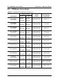
The following tables list the parameter options for the :TRACe:PREamble? command in
each supported measurement mode.
Cable & Antenna Parameter Names
Table 2-8.
Available Parameters in Cable & Antenna Mode (1 of 4)
Parameter Name
Description
SN
Instrument serial #
UNIT_NAME
Instrument name
TYPE
The data type (Setup or Data).
DESCR
Trace name
DATE
Trace date/time
BASE_VER
Base FW version
APP_NAME
Application name
APP_VER
Application FW version
APP_MODE
Application Mode
CHECKSUM
Checksum
DIST_UNITS
Distance units
AMPL_UNITS
y-axis value units
MEASUREMENT
Measurement
1PORT_DOMAIN
1-Port Domain
FREQ_START
Start Frequency
FREQ_STOP
Stop Frequency
DIST_START
Start distance
DIST_STOP
Stop distance
CAL_STATUS
Calibrate Status (On/Off)
SWEEP_TIME
Sweep time
SWEEP_TYPE
Sweep type (Single/Continuous)
MARKER_SELECTED
The selected marker
MARKER_TABLE
Marker table status (On/Off)
TRACE_VIEW
Trace View (View/Blank)
TRACE_STATE
Trace State (Write/Hold)
WINDOWING
Windowing Type (Rectangular/Nominal Side Lobe/
Low Side Lobe/Minimum Side Lobe)
CABLE
Cable index from the cable list
PROP_VEL
Propagation velocity
CABLE_LOSS
Cable Loss
CW_STATUS
RF Immunity (On/Off)
MW82119B PM
PN: 10580-00403 Rev. C
2-11
2-7
Parameter Names
Table 2-8.
Chapter 2 — Programming with SCPI
Available Parameters in Cable & Antenna Mode (2 of 4)
Parameter Name
Description
OUTPUT_POWER_LEVEL
Power Level (High/Low)
CURRENT_SIGNAL_STD
Current signal standard
RESOLUTION
Sweep Resolution (137/275/551)
SCALE
Y-axis scale
RF_SOURCE_POWER_LEVEL
Source Power Level
CAL_TEMP_WINDOW
Cal Temp window
CAL_COEFFICIENT_PTR
Calibrate coefficient
SMITH_CHART_TYPE
Smith chart type
DISPLAY_CHANNELS
Display Channels
ACTIVE_DISPLAY_CHANNEL
The current active display channel
NUM_OF_CHANNELS
Channel number
SEND_CAL_PROMPTS
Send Cal prompts
SET_SWEEP_DATA_TYPE
Set sweep data type
AVERAGING
Averaging
DISP_CHANNELS
Display channels
ACTIVE_DISP_CHANNEL
Active display channel
DMAX
Dmax
FAULT_RESOLUTION
Fault Resolution
SUGGESTED_SPAN
Suggested span
START_FREQ_STATUS
Start frequency status
AVERAGING_FACTOR
Averaging Factor.
AVERAGE_COUNT
Averaging count.
SCALE_RESOLUTION_RL_DIST
S11 Log Magnitude Fault Location scale resolution
SCALE_RESOLUTION_SWR
S11 VSWR scale resolution
SCALE_RESOLUTION_SWR_DIST
S11 VSWR Fault Location scale resolution
SCALE_RESOLUTION_CL
Cable loss Scale resolution
SCALE_RESOLUTION_IL
IL scale resolution
SCALE_RESOLUTION_IG
S21 Log Magnitude scale resolution
SCALE_RESOLUTION_PHASE_S11
S11 Phase scale resolution
REFERENCE_VALUE_PHASE_S11
S11 Phase reference value
REFERENCE_LINE_PHASE_S11
S11 Phase reference line
RL_DIST_BOTTOM
DTF Return Loss Bottom Value
SWR_DIST_TOP
DTF VSWR Top Value
SWR_DIST_BOTTOM
DTF VSWR Bottom Value
RL_MAG_TOP
Return Loss Top Value
2-12
PN: 10580-00403 Rev. C
MW82119B PM
Chapter 2 — Programming with SCPI
Table 2-8.
2-7
Parameter Names
Available Parameters in Cable & Antenna Mode (3 of 4)
Parameter Name
Description
RL_MAG_BOTTOM
Return Loss Bottom Value
SWR_MAG_TOP
VSWR Top Value
SWR_MAG_BOTTOM
VSWR Bottom Value
CL_MAG_TOP
Cable Loss Top Value
CL_MAG_BOTTOM
Cable Loss Bottom Value
S11_PHASE_TOP
1-Port Phase Top Value
S11_PHASE_BOTTOM
1-Port Phase Bottom Value
MKR_REF_FREQNx
Reference marker x frequency (where x is the marker
number 0–5)
MKR_REF_FLAGSx
Reference marker x flags:
MKR_FLAG_ON_OFF: 0x00000001
MKR_FLAG_DELTA_MKR: 0x00000020
MKR_FLAG_DATA_INVALID: 0x00000040
MKR_FLAG_DATA_STALE: 0x00000080
MKR_FLAG_SELECTED: 0x00000100
MKR_FLAG_DELT_DISPL_PER_HZ: 0x00000800
MKR_FLAG_TRACE_A: 0x00001000
MKR_FLAG_TRACE_B: 0x00002000
MKR_FLAG_TRACE_MASK: 0x00007000
MKR_DLT_FREQNx
Delta marker x frequency (where x is the marker
number 0–5)
MKR_DLT_FLAGSx
Delta marker x flags:
LIM_LFLAGS_UP-1
Upper limit flags:
LIMIT_FLAG_UPPER: 0x00000001
LIMIT_FLAG_ON: 0x00000004
LIMIT_FLAG_ALARM_ON: 0x00000002
LIMIT_FLAG_SEGMENTED: 0x00000020
LIMIT_FLAG_ALARM_EVENT: 0x00000040
LIMIT_FLAG_LEFT_OF_START_FREQ: 0x00000080
LIMIT_FLAG_RIGHT_OF_STOP_FREQ: 0x00000100
LIMIT_FLAG_MASK: 0x000007FF
LIM_NUMPTS_UP-1
Number of upper limit points
LIM_CURFRQ_UP-1
Upper limit current frequency
LIM_CURMAG_UP-1
Upper limit current magnitude
MW82119B PM
PN: 10580-00403 Rev. C
2-13
2-7
Parameter Names
Table 2-8.
Chapter 2 — Programming with SCPI
Available Parameters in Cable & Antenna Mode (4 of 4)
Parameter Name
Description
LIM_PFLAGS_UPx
Upper limit x flags (where x is the limit point number
starting with 0)
LIM_FREQNC_UPx
Upper limit point x freq (where x is the limit point
number starting with 0)
LIM_MAGNTD_UPx
Upper limit point x parameter (where x is the limit point
number starting with 0)
2-14
PN: 10580-00403 Rev. C
MW82119B PM
Chapter 3 — All Modes Programming
Commands
The Anritsu PIM Master is capable of producing 80 Watts of RF power in the
cellular communications bands. Users must take precautions to minimize
exposure to these RF fields:
Warning
Always terminate the PIM output port of the test equipment into a load, a
loaded line or a line that will radiate or absorb the energy before beginning a
PIM test.
Confirm that the PIM Master RF power is off after a PIM test.
Always confirm that the PIM RF power is off before disconnecting a coaxial
connection, otherwise RF burns may result. Immediate burns to fingers or
eyes can result from exposure to live connectors.
Ensure all antenna’s under test are placed so that no personnel are
exposed to RF levels that exceed the maximum allowable exposure.
The commands in this chapter are functional in all PIM Master modes of operation.
MW82119B PM
PN: 10580-00403 Rev. C
3-1
3-1
3-1
:FETCh:GPS Subsystem
Chapter 3 — All Modes Programming Commands
:FETCh:GPS Subsystem
The commands in this subsystem return the most recent measured GPS data.
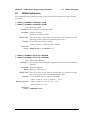
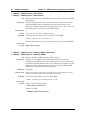
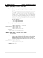
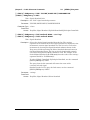
Fetch GPS Fix Data
:FETCh:GPS?
Description: Returns the most recent GPS fix information from the optional GPS
receiver.
The results are returned as a set of comma-delimited values in the
following format:
<fix status>, <date/time>, <latitude>, <longitude>
The <fix status> field is either “GOOD FIX” or “NO FIX”
depending on whether the GPS receiver is currently calculating position
data. If “NO FIX” is the value of the <fix status> field, then no
data follows.
The date and time (<date/time> field) are returned in the following
format:
Www Mmm dd hh:mm:ss yyyy
Where Www is the weekday in letters, Mmm is the month in letters, dd
is the day of the month, hh:mm:ss is the time (24-hour time), and
yyyy is the year.
Both <latitude> and <longitude> fields are expressed in radians.
A negative latitude value corresponds to a “south” reading. A negative
longitude value corresponds to a “west” reading.
Requires Option 31.
Syntax: :FETCh:GPS?
Cmd Parameters: NA (query only)
Query Responses: <string>, <arg>, <NR2>, <NR2> for parameter data of
<fix status>, <date/time>, <latitude>, <longitude>
Default Unit: Radians
Front Panel
Access: NA
3-2
PN: 10580-00403 Rev. C
MW82119B PM
Chapter 3 — All Modes Programming Commands
3-2
3-2
:INSTrument Subsystem
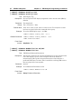
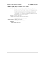
:INSTrument Subsystem
One instrument may contain many logical instrument “modes”. This subsystem controls the
selection of the current instrument mode.
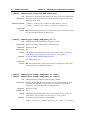
:INSTrument:CATalog:FULL?
Title: Query Available Modes
Description: Returns a comma-separated list of available modes. Mode names are
enclosed in double quotes (“ “). Immediately following the string name is
the application number. For example, an instrument with the High
Accuracy Power Meter (Option 19) would return the string:
“HI_PM”10,”MINIPIM”46. And an instrument with the Site Master
Option 331 and the High Accuracy Power Meter (Option 19) would
return the string: “VNA”2,“HI_PM”10,“MINIPIM”46.
Front Panel
Access: Shift-Mode (9), or Menu
:INSTrument:NSELect <integer>
:INSTrument:NSELect?
Title: Select Mode by Number
Description: Sets the instrument mode based on the value of <integer>. The query
version returns the number associated with the current mode. Use
:INSTrument:CATalog:FULL? to get a list of available mode names
and their integer representations.
Parameter: <integer>
Parameter Type: <integer>
Related Command: :INSTrument:CATalog:FULL?
:INITiate:CONTinuous
:INSTrument[:SELect]
:STATus:OPERation?
Front Panel
Access: Shift-Mode (9), or Menu
Note
Switching modes can take longer than 80 seconds, depending on the application.
Add a delay of at least 90 seconds between mode switch commands. Anritsu
Company advises you to set the remote PC time-out to 120 seconds in order to
avoid unexpected time-out errors.
MW82119B PM
PN: 10580-00403 Rev. C
3-3
3-2
:INSTrument Subsystem
Chapter 3 — All Modes Programming Commands
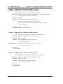
:INSTrument[:SELect] <string>
:INSTrument[:SELect]?
Title: Select Mode by Name
Description: Sets the instrument mode based on the mode name specified by
<string>. Enclose the <string> argument in single or double
quotes. The query version returns the name of the current mode. Use
:INSTrument:CATalog:FULL? to get a list of available modes.
Parameter: <string>
Related Command: :INSTrument:CATalog:FULL?
:INSTrument:NSELect
Front Panel
Access: Shift-Mode (9), or Menu
Note
3-4
Switching modes can take longer than 80 seconds, depending on the application.
Add a delay of at least 90 seconds between mode switch commands. Anritsu
Company advises you to set the remote PC time-out to 120 seconds in order to
avoid unexpected time-out errors.
PN: 10580-00403 Rev. C
MW82119B PM
Chapter 3 — All Modes Programming Commands
3-3
3-3
:MMEMory Subsystem
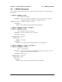
:MMEMory Subsystem
The Mass MEMory subsystem contains functions that provide access to the instrument’s
setup and data storage.
:MMEMory:DATA? <file name>
Title: Transfer Data
Description: Transfers the data stored in the given file from the instrument to the
controlling program. This is a query only. Data is transferred in the
form of <header><block>. The ASCII <header> specifies the
number of data byes. It looks like #AX, where A is the number of digits
in X and X is the number of bytes in <block>. <file name> should
be enclosed in either single quotes (‘ ’) or double quotes (“ ”) and should
contain a file extension (for example, .stp, .jpg), and the file must
not be larger than 262136 bytes. Use the command MMEMory:MSIS to
set the current storage location.
Parameter: <file name>
Front Panel
Access: NA
:MMEMory:MSIS INTernal|USB
:MMEMory:MSIS?
Title: Storage Location
Description: Sets the storage location. Setting the storage location to INTernal will
set the current storage location to be the internal memory. Setting the
storage location to USB will set the current storage location to be the
USB Flash drive. Note that the storage location can be set
independently and can be different for remote operation and front panel
operation. Changing the copy location remotely does not change the
location that is set and displayed on the front panel. Similarly, changing
the copy location via the front panel does not affect the location that is
used by the remote operation commands.
Note that the storage location must be available in order for it to be set.
Also note that the command will always succeed even if the external
memory device is not present.
Parameter: INTernal|USB
Parameter Type: <char>
Related Command: :MMEMory:MSIS:DESTination
MW82119B PM
PN: 10580-00403 Rev. C
3-5
:MMEMory:MSIS:COPY
Title: Copy From Current Location To Destination
Description: Copies all measurements, setups, and JPEG files that are stored in the
current storage location to the “copy to destination” location.
Related Command: :MMEMory:MSIS
:MMEMory:MSIS:DESTination
Front Panel
Access: Shift-File (7), Copy
3-6
PN: 10580-00403 Rev. C
MW82119B PM
Chapter 3 — All Modes Programming Commands
3-3
:MMEMory Subsystem
:MMEMory:MSIS:DESTination INTernal|USB
:MMEMory:MSIS:DESTination?
Title: Copy to Destination
Description: Sets the destination to which measurements and setups in the current
storage location are copied. Setting the location to INTernal copies
the files that are stored at the current storage location into the internal
memory when the command :MEMMory:MSIS:COPY is sent.
Setting the location to USB copies the files that are stored at the
current storage location into the USB Flash drive when the command
:MMEM:MSIS:COPY is sent.
Note that the storage location can be set independently and can be
different for remote operation and front panel operation. Changing the
save location remotely does not change the location that is set and
displayed on the front panel. Similarly, changing the save location via
the front panel does not affect the location that is used by the remote
operation commands. Also note that the command will always succeed
even if the external memory device is not present.
Parameter: INTernal|USB
Related Command: :MMEMory:MSIS
:MMEMory:MSIS:COPY
Front Panel
Access: Shift-File (7), Save (or Save Measurement), Change Save Location
:MMEMory:STORe:JPEG <file name>
Title: Save Screen as JPEG
Description: Saves the current screen measurement as a JPEG file. This will save
the screen as a JPEG file specified by <file name> with the
extension .jpg to the current storage location. <file name> should
be enclosed in either single quotes (‘ ’) or double quotes (“ ”) and should
not contain a file extension. Use the command MMEMory:MSIS to set
the current storage location.
Parameter: <file name>
Example: To save the screen into the file name “trace”:
:MMEMory:STORe:JPEG “trace”
Related Command: :MMEMory:DATA?
:MMEMory:MSIS INTernal|USB
Front Panel
Access: Shift-File (7), Save
MW82119B PM
PN: 10580-00403 Rev. C
3-7
3-4
3-4
[:SENSe]:GPS Subsystem
Chapter 3 — All Modes Programming Commands
[:SENSe]:GPS Subsystem
This subsystem contains commands that relate to the optional GPS (Global Positioning
System) on the instrument.
GPS On/Off
[:SENSe]:GPS
[:SENSe]:GPS?
Description: Enables/disables optional GPS capability. The query version returns 0
when the GPS is Off and returns 1 when the GPS is On.
Requires Option 31.
Syntax: [:SENSe]:GPS OFF|ON|0|1
[:SENSe]:GPS?
Cmd Parameters: <boolean> OFF|ON|0|1
Query Responses: <bNR1> 0|1
Default Value: Off
Front Panel
Access: Shift 8 (System), GPS, GPS On/Off
GPS Reset
[:SENSe]:GPS:RESet
Description: Resets optional GPS receiver.
Requires Option 31.
Syntax: [:SENSe]:GPS:RESet
Cmd Parameters: NA
Query Responses: NA (no query)
Front Panel
Access: Shift 8 (System), GPS, Reset
3-8
PN: 10580-00403 Rev. C
MW82119B PM
Chapter 3 — All Modes Programming Commands
3-4
[:SENSe]:GPS Subsystem
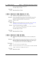
GPS Antenna Current
[:SENSe]:GPS:CURRent?
Description: Query only. Reads the current draw of the GPS antenna in mA.
Requires Option 31.
Syntax: [:SENSe]:GPS:CURRent?
Cmd Parameters: NA (query only)
Query Responses: <integer>
Front Panel
Access: Shift 8 (System), GPS, GPS Info
GPS Antenna Voltage
[:SENSe]:GPS:VOLTage 0|1
[:SENSe]:GPS:VOLTage?
Description: Sets and Reads the voltage setting for the GPS antenna. To set the
voltage to 3.3 V, send the 0 parameter after the command. To set the
voltage to 5 V, send the 1 parameter after the command. The query
version returns 0 for an antenna voltage of 3.3 V and returns 1 for an
antenna voltage of 5 V.
Requires Option 31.
Syntax: [:SENSe]:GPS:VOLTage 0|1
[:SENSe]:GPS:VOLTage?
Cmd Parameters: <boolean> 0|1
Query Responses: <bNR1> 0|1
Front Panel
Access: Shift 8 (System), GPS, GPS Voltage
Shift 8 (System), GPS, GPS Info
MW82119B PM
PN: 10580-00403 Rev. C
3-9
3-5
3-5
:SYSTem Subsystem
Chapter 3 — All Modes Programming Commands
:SYSTem Subsystem
This subsystem contains commands that affect instrument functionality that does not
directly relate to data collection, display, or transfer.
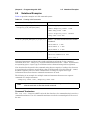
:SYSTem:OPTions?
Title: Query Installed Options
Description: Returns a string of the installed options. Options are separated by a “/”.
The string will return “NONE” if no options are installed.
Related Command: *IDN?
Front Panel
Access: NA
:SYSTem:PRESet
Title: Preset
Description: This command restores all application parameters to their factory
preset values. This does not modify system parameters such as
language, volume, or brightness.
Front Panel
Access: Shift-Preset (1), Preset
3-10
PN: 10580-00403 Rev. C
MW82119B PM
Chapter 4 — PIM Analyzer
Programming Commands
The Anritsu PIM Master is capable of producing 80 Watts of RF power in the
cellular communications bands. Users must take precautions to minimize
exposure to these RF fields:
Warning
Always terminate the PIM output port of the test equipment into a load, a
loaded line or a line that will radiate or absorb the energy before beginning a
PIM test.
Confirm that the PIM Master RF power is off after a PIM test.
Always confirm that the PIM RF power is off before disconnecting a coaxial
connection, otherwise RF burns may result. Immediate burns to fingers or
eyes can result from exposure to live connectors.
Ensure all antenna’s under test are placed so that no personnel are
exposed to RF levels that exceed the maximum allowable exposure.
4-1
SCPI Commands Introduction
The set of commands in this chapter are used to prepare the PIM Master hardware for the
selected measurements. These commands activate a specified measurement and set the
instrument to a wait-for-sweep mode, waiting for an :INITiate command to begin a
measurement. Ensure that your PIM Master is in the desired testing Mode before sending
SCPI commands.
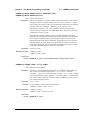
Example:
A typical command set for the PIM Master would include:
SENSe:PIManalyzer:MODe PIM|PIMSwp|DTP
(Sets mode to PIM vs. Time, Swept PIM, or DTP)
SENSe:PIManalyzer:MODe?
(Responds with PIM|PIMSwp|DTP, mode type PIM vs. Time, Swept PIM, or DTP)
[SENSe]:PIManalyzer:FREQuency:F1 1930000000
(Sets F1 to 1930 MHz)
[SENSe]:PIManalyzer:FREQuency:F2 1990000000
(Sets F2 to 1990 MHz)
[SENSe]:PIManalyzer:AUTorange 1
(Sets Amplitude to Auto Range)
[SENSe]:PIManalyzer:IMD:ORDer 3
(Sets center frequency of Rx to IM3)
[SENSe]:PIManalyzer:OUTPut:POWer 20
[SENSe]:PIManalyzer:TEST:DURation 10
INITiate:PIManalyzer:MEASure ON
MW82119B PM
(Sets power to 20 Watts)
(Sets the POWER ON time)
(Starts PIM measurement)
PN: 10580-00403 Rev. C
4-1
4-2
4-2
:CALCulate Subsystem
Chapter 4 — PIM Analyzer Programming Commands
:CALCulate Subsystem
The commands in this subsystem process data that has been collected via the SENSe
subsystem.
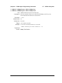
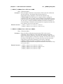
:CALCulate:DTPMeas:CABLoss
:CALCulate:DTPMeas:CABLoss?
Title: DTP cable loss
Description: Sets and queries DTP cable loss in dB/current distance unit.
Parameter: Cable loss in units of dB/distance
Parameter range is 0 dB/ft to 5 dB/ft (0 dB/m to 16.404 dB/m).
Default Value: None. If no value is sent, then no action occurs. To verify that a value
has been received, follow the command with a query.
Example: To set the cable loss to 0.1 dB/ft:
:CALCulate:DTPMeas:CABLoss
0.1
To query the cable loss:
:CALC:DTPM:CABL?
Front Panel
Access: Distance, More, Cable Loss
:CALCulate:DTPMeas:DISPlay:RESOlution
:CALCulate:DTPMeas:DISPlay:RESOlution?
Title: DTP data points
Description: Sets and queries DTP data points.
Parameter: 128, 255
Default Value: None. If no value is sent, then no action occurs. To verify that a value
has been received, follow the command with a query.
Example: To set the data point to 128:
:CALCulate:DTPMeas:DISPlay:RESOlution
128
To query the data point setting:
:CALC:DTPM:DISP:RESO?
Front Panel
Access: Distance, DTP Aid, Data Points
4-2
PN: 10580-00403 Rev. C
MW82119B PM
Chapter 4 — PIM Analyzer Programming Commands
4-2
:CALCulate Subsystem
:CALCulate:DTPMeas:DMAX?
Title: DTP maximum measurable distance
Description: Queries DTP maximum measurable distance in current distance unit.
Parameter: None
Default Value: None
Example: To query the DTP maximum measurable distance:
:CALC:DTPM:DMAX?
Related Command: :CALCulate:DTPMeas:STARt|STOP
:CALC:DTPM:STAR|STOP?
Front Panel
Access: Distance, DTP Aid, Stop Distance (Dmax)
:CALCulate:DTPMeas:FRESolution?
Title: DTP fault resolution
Description: Queries DTP fault resolution in current distance unit.
Parameter: None
Default Value: None
Example: To query the DTP fault resolution:
:CALC:DTPM:FRES?
Front Panel
Access: NA
MW82119B PM
PN: 10580-00403 Rev. C
4-3
4-2
:CALCulate Subsystem
Chapter 4 — PIM Analyzer Programming Commands
:CALCulate:DTPMeas:PVELocity
:CALCulate:DTPMeas:PVELocity?
Title: DTP cable propagation velocity index
Description: Sets and queries DTP cable propagation velocity index.
Parameter: 0.1 to 1.0
Default Value: None. If no value is sent, then no action occurs. To verify that a value
has been received, follow the command with a query.
Example: To set the cable propagation velocity index to 0.75:
:CALCulate:DTPMeas:PVELocity
0.75
To query the cable propagation velocity index:
:CALC:DTPM:PVEL?
Front Panel
Access: Distance, DTP Aid, Propagation Velocity
:CALCulate:DTPMeas:REFerence:AMPLitude
:CALCulate:DTPMeas:REFerence:AMPLitude?
Title: DTP Reference Line Amplitude
Description: Sets and queries the amplitude of the reference line in DTP mode in the
current units (dBm by default).
Parameter: 0 to –260
Parameter Type: <float>
Default Value: None. If no value is sent, then no action occurs. To verify that a value
has been received, follow the command with a query.
Example: To set the reference line to –100 dBm:
:CALCulate:DTPMeas:REFerence:AMPLitude –100
To query the reference line amplitude:
:CALC:DTPM:REF:AMPL?
Front Panel
Access: Shift-Limit (6), Amplitude
4-4
PN: 10580-00403 Rev. C
MW82119B PM
Chapter 4 — PIM Analyzer Programming Commands
4-2
:CALCulate Subsystem
:CALCulate:DTPMeas:REFerence[:STATe] OFF|ON|0|1
:CALCulate:DTPMeas:REFerence[:STATe]?
Title: DTP Reference Line State
Description: Turns the reference line ON or OFF. If the value is set to ON or to 1,
then the reference line is ON. If the value is set to OFF or to 0, then the
reference line is OFF. The query version of the command returns a 1 if
the reference line is ON and returns a 0 if it is OFF.
Parameter: OFF|ON|0|1
Parameter Type: <boolean>
Default Value: None
Example: To turn On the reference line:
:CALCulate:DTPMeas:REFerence ON
:CALCulate:DTPMeas:REFerence:STATe ON
:CALCulate:DTPMeas:REFerence:STATe 1
To turn Off the reference line:
:CALCulate:DTPMeas:REFerence OFF
:CALCulate:DTPMeas:REFerence:STATe 0
:CALCulate:DTPMeas:REFerence 0
To query the reference line state:
:CALC:DTPM:REF?
:CALC:DTPM:REF:STAT?
Front Panel
Access: Shift-Limit (6), On/Off
:CALCulate:DTPMeas:STARt
:CALCulate:DTPMeas:STARt?
Title: DTP Distance Start Setup
Description: Sets and queries DTP distance start. Parameters are m for meters and
ft for feet.
Parameter: m|ft
Default Value: Values in meters
Example: To set the DTP start distance to 10 feet:
:CALCulate:DTPMeas:STARt
MW82119B PM
10 ft
PN: 10580-00403 Rev. C
4-5
To query the DTP start distance:
:CALC:DTPM:STAR?
Related Command: :CALCulate:DTPMeas:STOP
100 ft
:CALC:DTPM:STOP?
:CALCulate:DTPMeas:DMAX?
:CALC:DTPM:DMAX?
Front Panel
Access: Distance, DTP Aid, Start Distance
:CALCulate:DTPMeas:STOP
:CALCulate:DTPMeas:STOP?
Title: DTP Distance Stop Setup
Description: Sets and queries DTP distance stop. Parameters are m for meters and
ft for feet.
Parameter: m|ft
Default Value: Values in meters
Example: To set the DTP stop distance to 100 feet:
:CALCulate:DTPMeas:STARt
100 ft
To query the DTP stop distance:
:CALC:DTPM:STOP?
Related Command: :CALCulate:DTPMeas:STARt
10 ft
:CALC:DTPM:STAR?
:CALCulate:DTPMeas:DMAX?
:CALC:DTPM:DMAX?
Front Panel
Access: Distance, DTP Aid, Stop Distance
4-6
PN: 10580-00403 Rev. C
MW82119B PM
Chapter 4 — PIM Analyzer Programming Commands
4-2
:CALCulate Subsystem
:CALCulate:DTPMeas:UNIT METers|FEET
:CALCulate:DTPMeas:UNIT?
Title: DTP distance unit
Description: Sets and queries DTP distance unit. Parameters are m for meters and
ft for feet.
Parameter: METers|FEET
Default Value: None. If no value is sent, then no action occurs. To verify that a value
has been received, follow the command with a query.
Example: To set the unit to meter:
:CALCulate:DTPMeas:UNIT
:CALC:DTPM:UNIT
METers
MET
To query the distance unit:
:CALC:DTPM:UNIT?
Front Panel
Access: Distance, Units
:CALCulate:DTPMeas:WINDow
:CALCulate:DTPMeas:WINDow?
Title: DTP Windowing
Description: Sets and queries the type of windowing in order of increasing side lobe
reduction. Windowing settings are: rectangular, nominal side lobe, low
side lobe, and minimum side lobe.
Parameter: RECTangular = Rectangular Windowing
NSLobe = Nominal Side Lobe Windowing
LSLobe = Low Side Lobe Windowing
MSLobe = Minimum Side Lobe Windowing
Default Value: None. If no value is sent, then no action occurs. To verify that a value
has been received, follow the command with a query.
Example: To set the Nominal Side Lobe Windowing:
:CALCulate:DTPMeas:WINDow
NSLobe
To query the type of Windowing:
:CALC:DTPM:WIND?
Front Panel
Access: Distance, More, Window
MW82119B PM
PN: 10580-00403 Rev. C
4-7
4-2
:CALCulate Subsystem
Chapter 4 — PIM Analyzer Programming Commands
:CALCulate:LIMit:ALARm ON|OFF|0|1
:CALCulate:LIMit:ALARm?
Title: Upper Limit Alarm On/Off
Description: Sets and queries limit alarm for PIM vs. Time and Swept PIM
measurement types. This alarm is associated only to the upper limit.
Lower limit does not have an associated alarm.
Parameter: Limit Alarm ON|OFF|0|1 (0 = On, 1 = Off)
Parameter Type: <boolean>
Default Value: Off
Example: To set the limit alarm:
:CALCulate:LIMit:ALARm
0
To query the limit alarm:
:CALC:LIM:ALAR?
Front Panel
Access: Shift-Limit (6), Limit Alarm
:CALCulate:LIMit:AMPLitude
:CALCulate:LIMit:AMPLitude?
Title: Set Limit Amplitude
Description: Sets and queries limit amplitude for PIM vs. Time and Swept PIM
measurement types. The amplitude will be associated with the
currently selected limit (upper/lower). The amplitude reference level
range is –50 dBm to –140 dBm. The upper and lower limits can be set
far beyond the reference level range, but such settings are of no
practical value.
Parameter: Magnitude (dBm)
Resolution: 0.1 dB
Default Value: None. If no value is sent, then no action occurs. To verify that a value
has been received, follow the command with a query.
Example: To set the limit amplitude to –120 dBm:
:CALCulate:LIMit:AMPLitude
–120
To query the limit amplitude:
:CALC:LIM:AMPL?
Front Panel
Access: Shift-Limit (6), Limit Move, Amplitude
4-8
PN: 10580-00403 Rev. C
MW82119B PM
Chapter 4 — PIM Analyzer Programming Commands
4-2
:CALCulate Subsystem
:CALCulate:LIMit:FAIL?
Title: Upper Limit Fail Check
Description: Checks if current trace data is failing Upper Limit dBm setting. If one
or more trace points fail, then the condition would indicate fail for a
response.
Parameter: 0/1 for Pass/Fail
Default Value: None
Example: To query if the current trace data is failing Upper Limit dBm setting:
:CALC:LIM:FAIL?
Front Panel
Access: NA, no direct access
Adjusting Limit Amplitude shows a number display change to red when
the limit line falls below the highest trace data point.
:CALCulate:LIMit[:STATe] OFF|ON|0|1
:CALCulate:LIMit[:STATe]?
Title: Limit State
Description: Turns the limit line ON or OFF. If the value is set to ON or to 1, then
the currently selected limit line is ON. If the value is set to OFF or to 0,
then the currently selected limit line is OFF. The query version of the
command returns a 1 if the currently selected limit line is ON and
returns a 0 if it is OFF.
Parameter: OFF|ON|0|1
Parameter Type: <boolean>
Default Value: OFF
Example: To turn on the limit line:
:CALCulate:LIMit
ON
:CALCulate:LIMit:STATe
ON
:CALCulate:LIMit:STATe
1
To turn off the limit line:
:CALCulate:LIMit
OFF
:CALCulate:LIMit:STATe
:CALCulate:LIMit
0
0
To query the limit line state:
:CALCul:LIM?
:CALC:LIM:STAT?
Front Panel
Access: Shift-Limit (6), Limit On/Off
MW82119B PM
PN: 10580-00403 Rev. C
4-9
4-2
:CALCulate Subsystem
Chapter 4 — PIM Analyzer Programming Commands
:CALCulate:LIMit:TYPe
:CALCulate:LIMit:TYPe?
Title: Limit Type Selection
Description: Sets and queries limits for PIM vs. Time and Swept PIM measurement
types. Selections are Upper/Lower.
Parameter: Limit value (0 = Upper, 1 = Lower)
Default Value: None. If no value is sent, then no action occurs. To verify that a value
has been received, follow the command with a query.
Example: To set the upper limit:
:CALCulate:LIMit:TYPe
0
To query the limit type:
:CALC:LIM:TYP?
Front Panel
Access: Shift-Limit (6), Limit
:CALCulate:LIMit:VALue
Title: Limit Value Magnitude Change
Description: Adds a magnitude change to the existing limit magnitude for
PIM vs. Time and Swept PIM measurement types.
Parameter: Magnitude (dB)
Resolution: 0.1 dB
Default Value: None
Example: To decrease the currently selected limit magnitude by 5 dB:
:CALCulate:LIMit:VALue
–5
Related Command: To query the limit amplitude:
:CALC:LIM:AMPL?
Front Panel
Access: Shift-Limit (6), Limit Move, Move Limit U/D
:CALCulate:MARKer:AOFF
Title: Turn All Markers Off
Description: Turns off all markers
Example: To turn Off all markers:
:CALC:MARK:AOFF
Front Panel
Access: Marker, All Markers Off
4-10
PN: 10580-00403 Rev. C
MW82119B PM
Chapter 4 — PIM Analyzer Programming Commands
4-2
:CALCulate Subsystem
:CALCulate:MARKer{1|2|3|4|5|6}:DELTa[:STATe] OFF|ON|0|1
:CALCulate:MARKer{1|2|3|4|5|6}:DELTa[:STATe]?
Title: Delta Marker State
Description: Sets the specified delta marker on or off. The query returns the state of
the specified delta marker (0|1)
Parameter: OFF|ON|0|1
Parameter Type: <boolean>
Default Value: OFF
Example: To turn on the delta marker #3:
:CALCulate:MARKer3:DELTa ON
:CALCulate:MARKer3:DELTa 1
:CALCulate:MARKer3:DELTa:STATe ON
:CALCulate:MARKer3:DELTa:STATe 1
To turn off delta marker #6:
:CALCulate:MARKer6:DELTa OFF
:CALCulate:MARKer6:DELTa:STATe OFF
:CALCulate:MARKer6:DELTa:STATe 0
To query the state of delta marker #2:
:CALC:MARK2:DELT?
:CALC:MARK2:DELT:STAT?
Front Panel
Access: Marker, Delta On Off
MW82119B PM
PN: 10580-00403 Rev. C
4-11
4-2
:CALCulate Subsystem
Chapter 4 — PIM Analyzer Programming Commands
:CALCulate:MARKer{1|2|3|4|5|6}:DELTa:TRACe 0|1
:CALCulate:MARKer{1|2|3|4|5|6}:DELTa:TRACe?
Title: Delta Marker Trace
Description: Sets the specified delta marker to a desired trace. Valid only for
Swept PIM mode.
Parameter: 0|1
Default Value: None. If no value is sent, then no action occurs. To verify that a value
has been received, follow the command with a query.
Example: To set delta marker #1 onto the fixed F2 sweep (Sweep #2):
:CALCulate:MARKer1:DELTa:TRACe 1
To set delta marker #2 onto the fixed F1 sweep (Sweep #1):
:CALC:MARK2:DELT:TRAC 0
To query which trace delta marker #6 is on:
:CALC:MARK6:DELT:TRAC?
Front Panel
Access: Marker, Marker, M#, Delta, Swap Marker Trace
:CALCulate:MARKer{1|2|3|4|5|6}:DELTa:X <x-parameter>
:CALCulate:MARKer{1|2|3|4|5|6}:DELTa:X?
Title: Delta Marker X Value
Description: Sets the location of the delta marker on the x-axis at the specified
location <x-parameter> + the reference marker x-axis.
<x-parameter> is defined in the current x-axis units. The query
version of the command returns the location of the delta marker on the
x-axis.
Parameter: <x-parameter>
Default Unit: Current x-axis unit
Example: If both the reference and delta marker #1 are currently at 1 GHz on the
x-axis, then send the command below to set the delta marker #1 to
2 GHz on the x-axis:
:CALCulate:MARKer1:DELTa:X 1GHz
Related Command: :CALCulate:MARKer[1]|2|3|4|5|6:X
Front Panel
Access: Marker, [Marker 1/2/3/4/5/6], Delta On, Arrow buttons
4-12
PN: 10580-00403 Rev. C
MW82119B PM
Chapter 4 — PIM Analyzer Programming Commands
4-2
:CALCulate Subsystem
:CALCulate:MARKer{1|2|3|4|5|6}:DELTa:Y?
Title: Delta Marker Read Y Value
Description: Reads the current Y value for the specified delta marker. The units are
the units of the y-axis.
Default Unit: Current y-axis unit
Example: To query the Y value of delta marker #6:
:CALC:MARK6:DELT:Y?
Front Panel
Access: NA
MW82119B PM
PN: 10580-00403 Rev. C
4-13
4-2
:CALCulate Subsystem
Chapter 4 — PIM Analyzer Programming Commands
:CALCulate:MARKer{1|2|3|4|5|6}[:STATe] OFF|ON|0|1
:CALCulate:MARKer{1|2|3|4|5|6}[:STATe]?
Title: Marker State
Description: Sets the specified marker on or off.
Parameter: OFF|ON|0|1
Parameter Type: <boolean>
Default Value: OFF
Example: To turn off reference marker #1:
:CALCulate:MARKer1:STATe OFF
To query the state of marker #6:
:CALC:MARK6:STAT?
Front Panel
Access: Marker, Marker, M#, On/Off
:CALCulate:MARKer{1|2|3|4|5|6}:TRACe 0|1
:CALCulate:MARKer{1|2|3|4|5|6}:TRACe?
Title: Marker Trace
Description: Sets the specified marker to a desired trace. Valid only for Swept PIM
mode.
Parameter: 0|1
Default Value: None. If no value is sent, then no action occurs. To verify that a value
has been received, follow the command with a query.
Example: To set marker #1 onto the fixed F2 sweep (Sweep #2):
:CALCulate:MARKer1:TRACe 1
To set marker #2 onto the fixed F1 sweep (Sweep #1):
:CALC:MARK2:TRAC 0
To query which trace marker #6 is on:
:CALC:MARK6:TRAC?
Front Panel
Access: Marker, Marker, M#, Swap Marker Trace
4-14
PN: 10580-00403 Rev. C
MW82119B PM
Chapter 4 — PIM Analyzer Programming Commands
4-2
:CALCulate Subsystem
:CALCulate:MARKer{1|2|3|4|5|6}:X <x-parameter>
:CALCulate:MARKer{1|2|3|4|5|6}:X?
Title: Marker X Value
Description: Sets the location of the marker on the x-axis at the specified location.
<x-parameter> is defined in the current x-axis units. The query
version of the command returns the location of the marker on the x-axis.
Note that the marker is snapped to the data point closest to the
specified value. If the specified marker is not On, then it is set to On. In
Swept PIM, Marker 1 is always On, but remains at trace peak and
cannot be moved. The query command reports the x-axis position for
Swept PIM.
Parameter: <x-parameter>
Default Unit: seconds in PIM versus Time measurement type
meters or feet in DTP measurement type
hertz in Swept PIM measurement type (query only)
Example: (In PIM vs. Time, DTP, or Swept PIM) To query the X value of reference
marker #3:
:CALC:MARK3:X?
(In PIM vs. Time) To set reference marker #3 to 1.5 seconds on the
x-axis:
:CALCulate:MARKer3:X 1.5
:CALCulate:MARKer3:X 1.5s
(In PIM vs. Time) To set reference marker #1 to 25 µs:
:CALCulate:MARKer:X 25
:CALCulate:MARKer1:X 25µs
(In DTP) To set reference marker #1 to 15 ft on the x-axis:
:CALCulate:MARKer:X 15
:CALCulate:MARKer1:X 15ft
To query the location of the marker on the x-axis:
:CALC:MARK:X?
Front Panel
Access: Marker, [Marker 1/2/3/4/5/6]
MW82119B PM
PN: 10580-00403 Rev. C
4-15
4-2
:CALCulate Subsystem
Chapter 4 — PIM Analyzer Programming Commands
:CALCulate:MARKer{1|2|3|4|5|6}:Y?
Title: Marker Read Y Value
Description: Reads the current Y value for the specified marker. The units are the
units of the y-axis.
Default Unit: Current y-axis unit
Example: To query the Y value of reference marker #4:
:CALC:MARK4:Y?
Front Panel
Access: NA
:CALCulate:SCALe:UNIT DBM|DBC
:CALCulate:SCALe:UNIT?
Title: Scale Unit
Description: Sets and queries the scale unit for PIM vs. Time, Distance-to-PIM, and
Swept PIM.
Parameter: DBM|DBC
Default Value: None. If no value is sent, then no action occurs. To verify that a value
has been received, follow the command with a query.
Example: To set the unit to dBm:
:CALCulate:SCALe:UNIT DBM
:CALC:SCAL:UNIT DBM
To query the scale unit:
:CALC:SCAL:UNIT?
Front Panel
Access: Amplitude, Units
4-16
PN: 10580-00403 Rev. C
MW82119B PM
Chapter 4 — PIM Analyzer Programming Commands
4-3
4-3
:CALibration Subsystem
:CALibration Subsystem
The commands in this subsystem control the system calibration.
:CALibration:PIManalyzer:FULL
:CALibration:PIManalyzer:FULL?
Title: Full Calibration
Description: Sets or resets the calibration for the instrument. This calibration is
done for all 3 measurement types at their current configuration (in
other words, output power, frequency (PVT only), and IMD order for
PVT and Swept PIM). The query returns 0 for “CAL OFF” or 1 for
“CAL ON”.
Parameter: OFF|ON|0|1
Parameter Type: <boolean>
Default Value: None
Example: To start full calibration:
:CALibration:PIManalyzer:FULL ON
To query the calibration state:
:CAL:PIM:FULL?
Front Panel
Access: Shift-Cal (2), Start Calibration
Shift-Cal (2), Reset Calibration
MW82119B PM
PN: 10580-00403 Rev. C
4-17
4-4
4-4
:DISPlay Subsystem
Chapter 4 — PIM Analyzer Programming Commands
:DISPlay Subsystem
The commands in this subsystem control parameters in the measurement display (the
sweep window).
:DISPlay:WINDow:Trace:Y[:SCALe]:PDIVision
:DISPlay:WINDow:Trace:Y[:SCALe]:PDIVision?
Title: PIM vs. Time and Swept PIM Scale (Not for DTP)
Description: Sets and queries Scale.
Parameter: Amplitude in dB/div
Default Value: 10 dB/div
Range: 1 dB/div to 15 dB/div
Example: To set PIM vs. Time or Swept PIM scale to 5 dB/div:
:DISPlay:WINDow:TRACe:Y[:SCALe]:PDIVision
5
Front Panel
Access: Amplitude, Scale
:DISPlay:WINDow:Trace:Y[:SCALe]:RLEVel
:DISPlay:WINDow:Trace:Y[:SCALe]:RLEVel?
Title: PIM vs. Time and Swept PIM Reference Level (Not for DTP)
Description: Sets and queries Reference Level.
Parameter: Amplitude in dBm
Default Value: –70 dBm
Range: –160 dBm to –50 dBm in 0.1 dB increments
Example: To set PIM vs. Time or Swept PIM reference level to –60 dBm:
:DISPlay:WINDow:TRACe:Y[:SCALe]:RLEVel
-60
Front Panel
Access: Amplitude, Reference Level
4-18
PN: 10580-00403 Rev. C
MW82119B PM
Chapter 4 — PIM Analyzer Programming Commands
4-5
4-5
:INITiate Subsystem
:INITiate Subsystem
The commands in this subsystem control the triggering of measurements.
:INITiate:PIManalyzer:MEASure OFF|ON|0|1
Title: Trigger PIM Analyzer Measurement
Description: This command triggers the start of the PIM Master measurement to
measure intermodulation distortion generated between the PIM
Analyzer and the system under test. It works with any of the available
measurement types: PIM vs. Time, DTP, Swept PIM. The
measurement will continue until the defined test duration time has
elapsed.
Sending this command with the OFF parameter or the 0 parameter
cancels the measurement.
Parameter: OFF|ON|0|1
Parameter Type: <boolean>
Front Panel
Access: Measurements, Test (Measure underlined)
:INITiate:PIManalyzer:PVT:ALLPower:CAL
Title: PvT All Power Levels Calibration
Description: This command triggers the start of the PIM vs. Time calibration for all
power levels.
Front Panel
Access: Shift-Cal (2), Custom Calibrations, Start Cal
(full name: Start Cal PIM vs. Time Only All Power Levels)
:INITiate:PIManalyzer:RESidual:CAL
Title: PIM Calibration: Current Mode Only
Description: This command triggers the start of the calibration for current
measurement mode only.
Front Panel
Access: None
MW82119B PM
PN: 10580-00403 Rev. C
4-19
4-6
4-6
:MMEMory Subsystem
Chapter 4 — PIM Analyzer Programming Commands
:MMEMory Subsystem
The commands in the Mass MEMory subsystem contain functions that provide access to the
setup and data storage of the instrument.
:MMEMory:CABLelist:RESet
Title: Reset Cable List to Default
Description: Clears the Cable List favorites and restores the factory-default cable list
information.
Front Panel
Access: Distance, More, Cable, Clear all Favorites
:MMEMory:LOAD:TRACe <integer>,<file name>
Title: Recall Measurement
Description: The instrument must be in the mode of the saved trace in order to recall
that trace. Use :INSTrument:SELect or :INSTrument:NSELect to
set the mode. Recalls a previously stored measurement trace from the
current storage location. The saved measurement trace to be loaded is
specified by <file name>. <file name> should be enclosed in
either single quotes (‘ ’) or double quotes (“ ”) and should contain a
file extension. Note that the trace specified by <file name> should be
available at the current mass storage location. Use the command
:MMEMory:MSIS to set the current mass storage location. The
<integer> parameter is not currently used, but it must be sent. Send
a 1.
File name extensions: “.pim” for PIM Analyzer
Note:
Extensions not available for T1 and HI_PM.
Parameter: <integer>, <file name>
Example: To recall trace with file name “trace”:
:MMEMory:LOAD:TRACe 1,”trace.pim”
Related Command: :MMEMory:STORe:TRACe
:MMEMory:MSIS INTernal|USB
Front Panel
Access: Shift-File (7), Recall Measurement
4-20
PN: 10580-00403 Rev. C
MW82119B PM
Chapter 4 — PIM Analyzer Programming Commands
4-6
:MMEMory Subsystem
:MMEMory:STORe:TRACe <integer>,<file name>
Title: Save Measurement
Description: Stores the trace into the file specified by <file name>.
<file name> should be enclosed in either single quotes (‘ ’) or
double quotes (“ ”) and should not contain a file extension. Use the
command :MMEMory:MSIS to set the current storage location. The
<integer> parameter is not currently used, but it must be sent. Send
a 0.
Parameter: <integer>, <file name>
Example: To save the trace into the file name “trace”:
:MMEMory:STORe:TRACe 0,”trace”
Related Command: :MMEMory:LOAD:TRACe
:MMEMory:MSIS INTernal|USB
Front Panel
Access: Shift-File (7), Save Measurement
:MMEMory:LOAD:STATe <integer>,<file name>
Title: Recall Setup
Description: Recalls a previously stored instrument setup in the current storage
location. The setup file to be loaded is specified by <file name>.
<file name> should be enclosed in either single quotes (‘ ’) or
double quotes (“ ”) and should contain a file extension “.stp”. Use the
command :MMEMory:MSIS to set the current storage location. The
<integer> parameter is not currently used, but it must be sent. Send
a 1.
Parameter: <integer>, <file name>
Example: To recall a previously stored instrument setup:
:MMEMory:LOAD:STATe 1,”setup.stp”
Related Command: :MMEMory:STORe:STATe
:MMEMory:MSIS INTernal|USB
Front Panel
Access: Shift-File (7), Recall, (select Setup from list)
MW82119B PM
PN: 10580-00403 Rev. C
4-21
4-6
:MMEMory Subsystem
Chapter 4 — PIM Analyzer Programming Commands
:MMEMory:STORe:STATe <integer>,<file name>
Title: Save Setup
Description: Stores the current setup into the file specified by <file name>.
<file name> should be enclosed in either single quotes (‘ ’) or
double quotes (“ ”) and should not contain a file extension “.stp”. Use
the command :MMEMory:MSIS to set the current storage location. The
<integer> parameter is not currently used, but it must be sent. Send
a 0.
Parameter: <integer>, <file name>
Example: To save the current instrument setup:
:MMEMory:STORe:STATe 0,”setup”
Related Command: :MMEMory:LOAD:STATe
:MMEMory:MSIS INTernal|USB
Front Panel
Access: Shift-File (7), Save, Change Type, (select Setup from list)
4-22
PN: 10580-00403 Rev. C
MW82119B PM
Chapter 4 — PIM Analyzer Programming Commands
4-7
4-7
:SENSe Subsystem
:SENSe Subsystem
The commands in this subsystem relate to device-specific parameters, not signal-oriented
parameters.
[:SENSe]:DTPMeas:AVERage:TYPE
[:SENSe]:DTPMeas:AVERage:TYPE?
Title: DTP Trace Mode
Description: Sets and queries DTP trace mode
Parameter: NORMal = normal
MAXHold = max trace hold
Default Value: None. If no value is sent, then no action occurs. To verify that a value
has been received, follow the command with a query.
Example: To set DTP trace mode to normal:
:SENSe:DTPMeas:AVERage:TYPE
NORMal
Front Panel
Access: Setup, Normal -> A / Max Hold -> A
[:SENSe]:DTPMeas:DISPlay:BOTTom
[:SENSe]:DTPMeas:DISPlay:BOTTom?
Title: DTP Display Bottom
Description: Sets and queries DTP display magnitude in the current units (dBm by
default).
Parameter: Bottom magnitude
Range: Bottom = –260 (top = 0)
Default Value: None. If no value is sent, then no action occurs. To verify that a value
has been received, follow the command with a query.
Example: To set the DTP display bottom to –100 dBm:
:SENSe:DTPMeas:DISPlay:BOTTom
Related Command: :SENSe:DTPMeas:DISPlay:TOP
–100.0
–15.0
:SENS:DTPM:DISP:TOP?
Front Panel
Access: Amplitude, Bottom
MW82119B PM
PN: 10580-00403 Rev. C
4-23
4-7
:SENSe Subsystem
Chapter 4 — PIM Analyzer Programming Commands
[:SENSe]:DTPMeas:DISPlay:TOP
[:SENSe]:DTPMeas:DISPlay:TOP?
Title: DTP Display Top
Description: Sets and queries DTP display magnitude in the current units (dBm by
default).
Parameter: Top magnitude
Range: Top = 0 (bottom = –260)
Default Value: None. If no value is sent, then no action occurs. To verify that a value
has been received, follow the command with a query.
Example: To set the DTP display top to –10 dBm:
:SENSe:DTPMeas:DISPlay:TOP
–10.0
Related Command: :SENSe:DTPMeas:DISPlay:BOTTom
–90.0
:SENS:DTPM:DISP:BOTT?
Front Panel
Access: Amplitude, Top
[:SENSe]:DTPMeas:ENREsolution ON|OFF
[:SENSe]:DTPMeas:ENREsolution?
Title: PIM Master Enhanced Resolution
Description: This feature estimates the location of PIM sources on the measurement
trace and displays up to 4 vertical impulse bars from bottom of
measurement grid to point on measurement trace that indicates a
predicted PIM source location. This is useful for resolving PIM sources
that are physically close together.
Parameter: ON|OFF
Example: To set Enhanced Resolution to On:
:SENSe:DTPMeas:ENREsolution ON
Front Panel
Access: Setup, Enhanced Resolution
4-24
PN: 10580-00403 Rev. C
MW82119B PM
Chapter 4 — PIM Analyzer Programming Commands
4-7
:SENSe Subsystem
[:SENSe]:PIManalyzer:AVERaging FAST|LOWNoise
[:SENSe]:PIManalyzer:AVERaging?
Title: PIM vs. Time Trace Mode.
Description: Low Noise provides improvement in measurement range. Fast provides
faster measurement updates (measurements per second). The query
returns FAST or LOWN (LOWNoise).
Parameter: FAST|LOWNoise
Range: FAST, Averaging is minimum
LOWNoise, Averaging is maximum
Example: To set the PIM Master measurement for maximum averaging:
:SENSe:PIManalyzer:AVERaging LOWNoise
Front Panel
Access: Setup, Trace Mode
[:SENSe]:PIManalyzer:AUTorange OFF|ON|0|1
[:SENSe]:PIManalyzer:AUTorange?
Title: PIM vs. Time Auto Range
Description: Sets and queries the Auto Range condition for PIM vs. Time
measurement.
Parameter: None
Range: 0|OFF, Auto Ranging is OFF
1|ON, Auto Ranging is ON
Example: To set the PIM Master for Auto Range:
:SENSe:PIManalyzer:AUTorange 1
Front Panel
Access: Amplitude, Auto Range
MW82119B PM
PN: 10580-00403 Rev. C
4-25
4-7
:SENSe Subsystem
Chapter 4 — PIM Analyzer Programming Commands
[:SENSe]:PIManalyzer:DTPMeas:LRDTf[:STATe]
[:SENSe]:PIManalyzer:DTPMeas:LRDTf[:STATe]?
Title: PIM Master Low Resolution DTF Sweep State
Description: Sets and queries whether a Low Resolution DTF sweep is performed
during a Distance-To-PIM measurement.
Parameter: ON|OFF
Example: To enable the Low Resolution DTF sweep:
:SENSe:PIManalyzer:DTPMeas:LRDTf ON
To query whether the Low Resolution DTF sweep is enabled:
:PIM:DTPM:LRDT?
Front Panel
Access: Setup, Low Resolution DTF
[:SENSe]:PIManalyzer:DTPMeas:LRDTf:STARt?
Title: PIM Master Low Resolution DTF Sweep Start Frequency
Description: Queries the DTF Sweep Start Frequency in Hz.
Parameter: Frequency in Hz
Example: To get the DTF Sweep Start Frequency:
:PIM:DTPM:LRDT:STAR?
Related Command: :SENSe:PIManalyzer:DTPMeas:LRDTf:STOP?
:PIM:DTPM:LRDT:STOP?
Front Panel
Access: NA
[:SENSe]:PIManalyzer:DTPMeas:LRDTf:STOP?
Title: PIM Master Low Resolution DTF Sweep Stop Frequency
Description: Queries the DTF Sweep Stop Frequency in Hz.
Parameter: Frequency in Hz
Example: To get the DTF Sweep Stop Frequency:
:PIM:DTPM:LRDT:STOP?
Front Panel
Access: NA
4-26
PN: 10580-00403 Rev. C
MW82119B PM
Chapter 4 — PIM Analyzer Programming Commands
4-7
:SENSe Subsystem
[:SENSe]:PIManalyzer:FREQuency:F1|2
[:SENSe]:PIManalyzer:FREQuency:F1|2?
Title: PIM Master Frequency Setup
Description: Sets the PIM vs. Time carrier frequencies, calculates the IMx Order
frequency, and sets the instrument to display the corresponding IMx
frequency.
Parameter: Frequency in Hz
Default Unit: Hz
Ranges: PIM Master option dependent (for a list of ranges, refer to Table B-1,
“PIM Master Carrier Bands and Frequencies” on page B-2)
Example: To set the PIM vs. Time frequency F2 for 1990 MHz:
:SENSe:PIManalyzer:FREQuency:F2
1990000000
To get the PIM vs. Time frequency F1:
PIM:FREQ:F1?
Front Panel
Access: Freq, Carrier F1|Carrier F2
[:SENSe]:PIManalyzer:FREQuency:STEP
[:SENSe]:PIManalyzer:FREQuency:STEP?
Title: PIM Master Frequency Sweep Step Size
Description: Sets Frequency Step Size for Swept PIM and Spectrum View
measurement modes. The instrument may take up to 5 seconds to
update this parameter and all dependent configurations.
Parameter: Frequency in Hz
Ranges: 100 kHz to 1000 kHz in 100 kHz increments
Example: To set the step size to 100 kHz:
:SENSe:PIManalyzer:FREQuency:STEP
100000
To get the frequency step size:
PIM:FREQ:STEP?
Front Panel
Access: Freq, Step Size
MW82119B PM
PN: 10580-00403 Rev. C
4-27
4-7
:SENSe Subsystem
Chapter 4 — PIM Analyzer Programming Commands
[:SENSe]:PIManalyzer:IMD:ORDer
[:SENSe]:PIManalyzer:IMD:ORDer?
Title: Measurement Receiver / PIM Master Intermodulation Distortion (IMD)
Order Setup
Description: Sets the measurement receiver center frequency to receive one of the
following IMDs from the PIM Master measurement system: 3/5/7.
The query command returns the possible strings “3rd”, “5th”, and “7th”
depending on the current selection of IMD Order.
Default Value: 3
Range: 3, 5, and 7 are the only acceptable values.
Example: To set the measurement receiver for the 5th order IMD:
:SENSe:PIManalyzer:IMD:ORDer
5
Sets the measurement receiver center frequency to the 5th order IMD.
Front Panel
Access: Freq, Intermod Order
[:SENSe]:PIManalyzer:IMFReq:BAND LOW|HIGH
[:SENSe]:PIManalyzer:IMFReq:BAND?
Title: Optional High/Low IMD frequency band selection
Description: Sets the receive IMD measurement frequency band only for the
LTE-based 700 MHz options. This command works for all options that
have band switching functionality, such as Option 210, Option 702, and
Option 194. The command and the query are ignored by MW82119B
PIM Masters with other instrument options.
Parameter: LOW|HIGH
Default Value: None. If no value is sent, then no action occurs. To verify that a value
has been received, follow the command with a query.
Example: To set the measurement receiver to High Band:
:SENSe:PIManalyzer:IMFReq:BAND
HIGH
Front Panel
Access: PIM vs. Time and Swept PIM:
Freq, High/Low Band Select
Distance-to-PIM:
Distance, High/Low Band Select
4-28
PN: 10580-00403 Rev. C
MW82119B PM
Chapter 4 — PIM Analyzer Programming Commands
4-7
:SENSe Subsystem
[:SENSe]:PIManalyzer:MEASure:STATus?
Title: PIM Analyzer Current Measurement Status
Description: The query returns the current measurement status of the measurement
receiver/PIM Analyzer measurement system. Because the measurement
system can run for the maximum time duration, the query serves to
indicate if the measurement is still in process. This command works
with any of the available measurement modes: PIM vs. Time, DTP, and
Swept PIM.
Range: 0, Measurement is OFF
1, Measurement is ON
[:SENSe]:PIManalyzer:MEASure:VALue?
Title: Measurement Receiver Measured Value From PIM Master
Measurement Setup
Description: The query returns the last measured value in both dBc and dBm. For
example, if the output power is set to 43 dBm, and a PIM value of
–80 dBm was read, then this command would return: –123.0, –80.0
Parameter: <amplitude>
Default Unit: dBc/dBm
Front Panel
Access: N/A. Intermodulation distortion value is displayed in the lower
measurement box as “PIM”.
[:SENSe]:PIManalyzer:MODe PIM|PIMSwp|DTP|SPECTRUM_VIEW
[:SENSe]:PIManalyzer:MODe?
Title: PIM Analyzer Mode, Set or Request
Description: Puts the system into PIM vs. Time (PIM), Swept PIM (PIMSwp),
Distance-to-PIM (DTP), or Spectrum View (SPECTRUM_VIEW)
measurement mode. The query reports the current system mode.
Changing to Swept PIM mode can take as long as 20 seconds.
Parameter: PIM|PIMSwp|DTP|SPECTRUM_VIEW
Query Response: PIM (PIM vs. Time)
PIMSwp (Swept PIM)
DTP (Distance-to-PIM)
SPECTRUM_VIEW (Spectrum View)
Default Value: None. If no value is sent, then no action occurs. To verify that a value
has been received, follow the command with a query.
Example: To set the PIM Analyzer mode to measure Distance-to-PIM:
:SENSe:PIManalyzer:MODe DTP
MW82119B PM
PN: 10580-00403 Rev. C
4-29
4-7
:SENSe Subsystem
Chapter 4 — PIM Analyzer Programming Commands
To query the state of the PIM Analyzer system:
:SENS:PIM:MOD?
Front Panel
Access: Measurements, PIM|Distance-to-PIM|Swept PIM|
Noise Floor Measurements| Spectrum View
[:SENSe]:PIManalyzer:OUTPut:POWer
[:SENSe]:PIManalyzer:OUTPut:POWer?
Title: PIM Analyzer Output Power
Description: Sets the deliverable output (in dBm) from the PIM Analyzer to the
system under test.
Parameter: dBm input with 0.1 dBm resolution
Default Value: None. If no value is sent, then no action occurs. To verify that a value
has been received, follow the command with a query.
Range: 20 dBm to 46 dBm
Example: To set the PIM Analyzer output power to 43.5 dBm:
:SENSe:PIManalyzer:OUTPut:POWer
43.5
Front Panel
Access: PIM vs. Time and Swept PIM: Setup, PIM Aid, Output Power
PIM vs. Time and Swept PIM: Freq, PIM Aid, Output Power
DTP: Distance, DTP Aid, Output Power
DTP: Setup, DTP Aid, Output Power
[:SENSe]:PIManalyzer:RF:OUTput
[:SENSe]:PIManalyzer:RF:OUTput?
ON|OFF
Title: PIM vs. Time – Set RF Out On/Off
Description: This controls whether the RF is ON during a measurement, which
corresponds to Normal and Noise Floor PVT measurements.
Parameter: ON|OFF
Default Value: ON|OFF
Range: 20 dBm to 46 dBm
Example: To turn on RF:
[:SENSe]:PIManalyzer:OUTPut:POWer
43.5
Front Panel
Access: Measurements, PIM vs. Time, Test
4-30
PN: 10580-00403 Rev. C
MW82119B PM
Chapter 4 — PIM Analyzer Programming Commands
4-7
:SENSe Subsystem
[:SENSe]:PIManalyzer:SPECtrum:CURRent:MEASure:VALue?
Title: Measured Noise Floor Value from PIM Master
Description: The query returns the latest measured value of Spectrum View in dBm.
Related Command: [:SENSe]:PIManalyzer:SPECtrum:CURRent:FREQuency?
[:SENSe]:PIManalyzer:SPECtrum:MAX:MEASure:VALue?
Front Panel
Access: N/A. Signal value is displayed in the lower measurement box as
“Signal Amplitude”.
[:SENSe]:PIManalyzer:SPECtrum:CURRent:FREQuency?
Title: Measured Noise Floor Frequency from PIM Master
Description: The query returns the latest measured frequency of Spectrum View
in Hz.
Related Command: [:SENSe]:PIManalyzer:SPECtrum:CURRent:MEASure:VALue?
[:SENSe]:PIManalyzer:SPECtrum:MAX:FREQuency?
Front Panel
Access: N/A. Signal frequency is displayed in the lower measurement box after
the “Signal Amplitude” in dBm.
[:SENSe]:PIManalyzer:SPECtrum:MAX:MEASure:VALue?
Title: Maximum Measured Noise Floor Value from PIM Master
Description: The query returns the maximum measured value of Spectrum View
in dBm.
Related Command: [:SENSe]:PIManalyzer:SPECtrum:MAX:FREQuency?
[:SENSe]:PIManalyzer:SPECtrum:CURRent:MEASure:VALue?
Front Panel
Access: N/A. Maximum signal value is displayed in the lower measurement box
as “Max Amplitude”.
MW82119B PM
PN: 10580-00403 Rev. C
4-31
4-7
:SENSe Subsystem
Chapter 4 — PIM Analyzer Programming Commands
[:SENSe]:PIManalyzer:SPECtrum:MAX:FREQuency?
Title: Frequency at Maximum Measured Noise Floor Value from PIM Master
Description: The query returns the frequency of the maximum signal measured in
Spectrum View in Hz.
Related Command: [:SENSe]:PIManalyzer:SPECtrum:MAX:MEASure:VALue?
[:SENSe]:PIManalyzer:SPECtrum:CURRent:FREQuency?
Front Panel
Access: N/A. Maximum signal frequency is displayed in the lower measurement
box after the Max Amplitude dBm value.
[:SENSe]:PIManalyzer:SWEEp:FREQuency:F1|2?
Title: PIM Master Swept PIM F2 Stop Frequency Setup
Description: Queries the Swept PIM Fixed F1 or F2 frequency.
Parameter: Frequency in Hz
Default Unit: Hz
Range: PIM Master option dependent (for a list of ranges, refer to Table B-1,
“PIM Master Carrier Bands and Frequencies” on page B-2).
Example: To get the Swept PIM Fixed F2 frequency:
PIM:SWEE:FREQ:F2?
Front Panel
Access: NA Note that fixed F1 and F2 frequencies are displayed in the lower
measurement box in Swept Pim mode.
[:SENSe]:PIManalyzer:SWEEp:FREQuency:F1:STARt
[:SENSe]:PIManalyzer:SWEEp:FREQuency:F1:STARt?
Title: PIM Master Swept PIM F1 Start Frequency Setup
Description: Sets the Swept PIM F1 start frequency for the Fixed F2 sweep, then
calculates the IMx sweep frequencies, and sets the instrument to
display the corresponding IMx sweep frequencies.
Parameter: Frequency in Hz
Default Unit: Hz
Range: PIM Master option dependent (for a list of ranges, refer to Table B-1,
“PIM Master Carrier Bands and Frequencies” on page B-2).
Example: To set the F1 start frequency to 1990 MHz:
:SENSe:PIManalyzer:SWEEp:FREQuency:F1:STARt 1990000000
4-32
PN: 10580-00403 Rev. C
MW82119B PM
Chapter 4 — PIM Analyzer Programming Commands
4-7
:SENSe Subsystem
To get the Swept PIM F1 start frequency:
PIM:SWEE:FREQ:F1:STAR?
Front Panel
Access: Freq, Swept PIM Aid, F1 Start
[:SENSe]:PIManalyzer:SWEEp:FREQuency:F1:STOP
[:SENSe]:PIManalyzer:SWEEp:FREQuency:F1:STOP?
Title: PIM Master Swept PIM F1 Stop Frequency Setup
Description: Sets the Swept PIM F1 stop frequency for the Fixed F2 sweep, then
calculates the IMx sweep frequencies, and sets the instrument to
display the corresponding IMx sweep frequencies.
Parameter: Frequency in Hz
Default Unit: Hz
Range: PIM Master option dependent (for a list of ranges, refer to Table B-1,
“PIM Master Carrier Bands and Frequencies” on page B-2).
Example: To set the F1 stop frequency to 2110 MHz:
:SENSe:PIManalyzer:SWEEp:FREQuency:F1:STOP 2110000000
To get the Swept PIM F1 stop frequency:
PIM:SWEE:FREQ:F1:STOP?
Front Panel
Access: Freq, Swept PIM Aid, F1 Stop
[:SENSe]:PIManalyzer:SWEEp:FREQuency:F2:STARt
[:SENSe]:PIManalyzer:SWEEp:FREQuency:F2:STARt?
Title: PIM Master Swept PIM F2 Start Frequency Setup
Description: Sets the Swept PIM F2 start frequency for the Fixed F1 sweep, then
calculates the IMx sweep frequencies, and sets the instrument to
display the corresponding IMx sweep frequencies.
Parameter: Frequency in Hz
Default Unit: Hz
Range: PIM Master option dependent (for a list of ranges, refer to Table B-1,
“PIM Master Carrier Bands and Frequencies” on page B-2).
Example: To set the F2 start frequency to 758 MHz:
:SENSe:PIManalyzer:SWEEp:FREQuency:F2:STARt 758000000
MW82119B PM
PN: 10580-00403 Rev. C
4-33
4-7
:SENSe Subsystem
Chapter 4 — PIM Analyzer Programming Commands
To get the Swept PIM F2 start frequency:
PIM:SWEE:FREQ:F2:STAR?
Front Panel
Access: Freq, Swept PIM Aid, F2 Start
[:SENSe]:PIManalyzer:SWEEp:FREQuency:F2:STOP
[:SENSe]:PIManalyzer:SWEEp:FREQuency:F2:STOP?
Title: PIM Master Swept PIM F2 Stop Frequency Setup
Description: Sets the Swept PIM F2 stop frequency for the Fixed F1 sweep, then
calculates the IMx sweep frequencies, and sets the instrument to
display the corresponding IMx sweep frequencies.
Parameter: Frequency in Hz
Default Unit: Hz
Range: PIM Master option dependent (for a list of ranges, refer to Table B-1,
“PIM Master Carrier Bands and Frequencies” on page B-2).
Example: To set the F2 stop frequency to 768 MHz:
:SENSe:PIManalyzer:SWEEp:FREQuency:F2:STOP 768000000
To get the Swept PIM F2 stop frequency:
PIM:SWEE:FREQ:F2:STOP?
Front Panel
Access: Freq, Swept PIM Aid, F2 Stop
[:SENSe]:PIManalyzer:SWEEp:IMD:ORDer
[:SENSe]:PIManalyzer:SWEEp:IMD:ORDer?
Title: PIM Analyzer Swept PIM Intermodulation Distortion (IMD) Order
Setup
Description: Sets the measurement receiver center frequency to receive one of the
following IMDs from the PIM Analyzer measurement system: 3/5/7.
The query command returns the possible strings “3rd”, “5th”, and
“7th”, depending on the current selection of IMD Order.
Default Value: 3
Range: 3, 5, and 7 are the only acceptable values.
Example: To set the measurement receiver center frequency to the 5th order IMD:
:SENSe:PIManalyzer:SWEEp:IMD:ORDer 5
Front Panel
Access: Freq, Intermod Order
4-34
PN: 10580-00403 Rev. C
MW82119B PM
Chapter 4 — PIM Analyzer Programming Commands
4-7
:SENSe Subsystem
[:SENSe]:PIManalyzer:TESt:DURation
[:SENSe]:PIManalyzer:TESt:DURation?
Title: PIM Test Measurement Test Duration
Description: Sets the amount of time in seconds the PIM Master will be on for
intermodulation distortion measurements.
Parameter: <time>
Default Value: 20
Default Unit: Seconds
Range: 1.0 to 1200.0 seconds
Example: To set the test duration time to 5 seconds:
:SENSe:PIManalyzer:TESt:DURation
5.0
Front Panel
Access: Setup, Test Duration
MW82119B PM
PN: 10580-00403 Rev. C
4-35
4-8
:TRACe Subsystem
4-8
Chapter 4 — PIM Analyzer Programming Commands
:TRACe Subsystem
This subsystem contains commands related to the transfer of trace data to and from the
instrument.
:TRACe[:DATA]? X
Title: Trace Data Transfer
Description: This command transfers trace data from the instrument to the
controller. Before executing this command, the instrument must be set
to the desired measurement.
For Distance-to-PIM measurements, the parameter X is 1, 2, or 3.
1 = Active Trace
2 = DTP Overlay Trace
3 = DTF Overlay Trace.
For Swept PIM measurements, the parameter X is either 1 or 2.
1 = Fixed F1 trace data
2 = Fixed F2 trace data
For PIM vs. Time measurements, X should not be specified.
Parameter: NULL|1|2|3
Parameter Type: <char>
Example: To query the data points of a PIM vs. Time trace:
:TRAC:DATA?
:TRAC?
To query the data points of a Swept PIM Fixed F1 trace:
:TRAC:DATA? 1
:TRAC?
1
To query the data points of a DTP active trace:
:TRAC:DATA? 1
:TRAC? 1
To query the data points of a DTF overlay trace:
:TRAC:DATA? 3
:TRAC?
3
Front Panel
Access: NA
4-36
PN: 10580-00403 Rev. C
MW82119B PM
Chapter 4 — PIM Analyzer Programming Commands
MW82119B PM
PN: 10580-00403 Rev. C
4-8
:TRACe Subsystem
4-37
4-8
4-38
:TRACe Subsystem
Chapter 4 — PIM Analyzer Programming Commands
PN: 10580-00403 Rev. C
MW82119B PM
Chapter 5 — Cable & Antenna
Commands
5-1
:CALCulate Subsystem
The commands in this subsystem process data that has been collected via the SENSe
subsystem.
:CALCulate:LIMit:ALARm OFF|ON|0|1
:CALCulate:LIMit:ALARm?
Title: Limit Alarm
Description: Enables/disables the currently active limit line alarm. Setting the value
to ON or 1 will turn on the limit alarm. Setting the value to OFF or 0
will turn off the limit alarm. The query version of the command returns
a 1 if the currently selected limit line alarm is set to ON and returns 0 if
OFF.
Parameter: OFF|ON|0|1
Parameter Type: <boolean>
Default Value: OFF
Example: To turn off limit alarm:
:CALCulate:LIMit:ALARm OFF
:CALCulate:LIMit:ALARm 0
To turn on limit alarm:
:CALCulate:LIMit:ALARm ON
:CALCulate:LIMit:ALARm 1
Front Panel
Access: Shift-6 (Limit), Limit Alarm
:CALCulate:LIMit:CLEar
Title: Clear Selected Limit
Description: Deletes all limit points for the currently active limit line.
Front Panel
Access: Shift-6 (Limit), Clear Limit
:CALCulate:LIMit:POINt:ADD
Title: Add Limit Point
Description: Adds a new limit point to the currently active limit line.
Front Panel
Access: Shift-6 (Limit), Multi-Segment Edit, Add Point
MW82119B PM
PN: 10580-00403 Rev. C
5-1
5-1
:CALCulate Subsystem
Chapter 5 — Cable & Antenna Commands
:CALCulate:LIMit:POINt:FREQuency <freq>
:CALCulate:LIMit:POINt:FREQuency?
Title: Limit Point Frequency
Description: Sets the limit point frequency of the current selected limit.
Parameter: <freq>
Default Unit: Hz
Front Panel
Access: Shift-6 (Limit), Multi-Segment Edit, Point Freq
:CALCulate:LIMit:POINt:VALue <value>
:CALCulate:LIMit:POINt:VALue?
Title: Limit Point Value
Description: Sets the limit point value of the current selected limit. The <value>
parameter is the limit point value in dB or time units for group delay.
Parameter: <value>
Default Unit: Current active value unit.
Front Panel
Access: Shift-6 (Limit), Multi-Segment Edit, Point Value
:CALCulate:LIMit:POINt?
Title: Number of Limit Points
Description: Returns the number of points currently in the selected limit line.
5-2
PN: 10580-00403 Rev. C
MW82119B PM
Chapter 5 — Cable & Antenna Commands
5-1
:CALCulate Subsystem
:CALCulate:LIMit[:STATe] OFF|ON|0|1
:CALCulate:LIMit[:STATe]?
Title: Limit State
Description: Turns the limit line ON or OFF. If the value is set to ON or 1, the
currently selected limit line is ON. If the value is set to OFF or 0, the
currently selected limit line is OFF. The query version of the command
returns a 1 if the currently selected limit line is ON and returns a 0 if
OFF.
Parameter: OFF|ON|0|1
Parameter Type: <boolean>
Default Value: OFF
Example: To turn on the limit line:
:CALCulate:LIMit ON
:CALCulate:LIMit:STATe ON
:CALCulate:LIMit:STATe 1
To turn off the limit line:
:CALCulate:LIMit OFF
:CALCulate:LIMit:STATe 0
:CALCulate:LIMit 0
Front Panel
Access: Shift-6 (Limit), Limit On/Off
:CALCulate:MARKer:AOFF
Title: Turn All Markers Off
Description: Turns off all markers.
Front Panel
Access: Marker, All Markers Off
MW82119B PM
PN: 10580-00403 Rev. C
5-3
5-1
:CALCulate Subsystem
Chapter 5 — Cable & Antenna Commands
:CALCulate:MARKer:TABLe:DATA?
Title: Marker Table Data
Description: Reports marker information similar to the Marker table. The response
begins with an ASCII header. The header specifies the number of
following bytes. It looks like #AX, where A is the number of digits in X
and X is the number of bytes that follow the header. Parameters are
returned in comma-delimited ASCII format. Each parameter is
returned as “NAME=VALUE[UNITS].”
Parameter Name
Description
MKR_REFx
Reference marker state
MKR_DLTx
Delta marker state.
MKR_REF_FREQNx
Reference marker x frequency
MKR_DLT_FREQNx
Delta marker x frequency
MKR_REF_AMPLy
Reference marker y-axis
MKR_DLT_AMPL
Delta marker y magnitude.
x = marker 1 to 6.
Front Panel
Access: Marker, Marker Table On
:CALCulate:MARKer:TABLe[:STATe] OFF|ON|0|1
:CALCulate:MARKer:TABLe[:STATe]?
Title: Marker Table State
Description: Turns the Marker Table on or off. Setting the value to ON or 1 will turn
on the marker table. Setting the value to OFF or 0 will turn off the
marker table.
Parameter: OFF|ON|0|1
Parameter Type: <boolean>
Default Value: OFF
Example: To turn on marker table:
:CALCulate:MARKer:TABLe ON
:CALCulate:MARKer:TABLe 1
Front Panel
Access: Marker, Marker Table
5-4
PN: 10580-00403 Rev. C
MW82119B PM
Chapter 5 — Cable & Antenna Commands
5-1
:CALCulate Subsystem
:CALCulate:MARKer{1|2|3|4|5|6}:DELTa:X <x-parameter>
:CALCulate:MARKer{1|2|3|4|5|6}:DELTa:X?
Title: Delta Marker X Value
Description: Sets the location of the delta marker on the x-axis at the specified
location <x-parameter> + the reference marker x-axis. <x-parameter> is
defined in the current x-axis units. The query version of the command
returns the location of the delta marker on the x-axis.
Parameter: <x-parameter>
Default Unit: Current x-axis unit
Example: If both the reference and delta marker #1 is currently at 1 GHz on the
x-axis, send the command below to set the delta marker #1 to 2 GHz on
the x-axis:
:CALCulate:MARKer1:DELTa:X 1GHz
Related Command: :CALCulate:MARKer[1]|2|3|4|5|6:X
Front Panel
Access: Marker, Delta
:CALCulate:MARKer{1|2|3|4|5|6}:DELTa:Y?
Title: Delta Marker Read Y Value
Description: Reads the current Y value for the specified delta marker. The units are
the units of the y-axis.
Default Unit: Current y-axis unit
:CALCulate:MARKer{1|2|3|4|5|6}:DELTa[:STATe] OFF|ON|0|1
:CALCulate:MARKer{1|2|3|4|5|6}:DELTa[:STATe]?
Title: Delta Marker State
Description: Sets the specified delta marker on or off.
Parameter: OFF|ON|0|1
Parameter Type: <boolean>
Default Value: OFF
Example: To turn on delta marker #3:
:CAL1Culate:MARKer3:DELTa ON
:CALCulate:MARKer3:DELTa 1
:CALCulate:MARKer3:DELTa:STATe ON
:CALCulate:MARKer3:DELTa:STATe 1
To turn off delta marker #6
:CALCulate:MARKer6:DELTa OFF
:CALCulate:MARKer6:DELTa:STATe OFF
:CALCulate:MARKer6:DELTa:STATe 0
Front Panel
Access: Marker, Delta
MW82119B PM
PN: 10580-00403 Rev. C
5-5
5-1
:CALCulate Subsystem
Chapter 5 — Cable & Antenna Commands
:CALCulate:MARKer{1|2|3|4|5|6}:PEAK
Title: Marker Peak Search
Description: Puts the specified marker at the maximum value in the trace.
Front Panel
Access: Marker, Marker [1/2/3/4/5/6], Marker to Peak
:CALCulate:MARKer{1|2|3|4|5|6}:VALLey
Title: Marker Valley Search
Description: Puts the specified marker at the minimum value in the trace.
Front Panel
Access: Marker, Marker [1/2/3/4/5/6], Marker to Valley
:CALCulate:MARKer{1|2|3|4|5|6}:X <x-parameter>
:CALCulate:MARKer{1|2|3|4|5|6}:X?
Title: Marker X Value
Description: Sets the location of the marker on the x-axis at the specified location.
<x-parameter> is defined in the current x-axis units. The query version
of the command returns the location of the marker on the x-axis. Note
that the marker is snapped to the data point closest to the specified
value. If the specified marker is not on, it is set to on.
Parameter: <x-parameter>
Default Unit: Current x-axis unit
Example: To set reference marker #2 to 1GHz on the x-axis:
:CALCulate:MARKer2:X 1GHz
To set reference marker #1 to 1.5 GHz on the x-axis:
:CALCulate:MARKer:X 1.5GHz
:CALCulate:MARKer1:X 1.5GHz
Front Panel
Access: Marker, Marker [1/2/3/4/5/6]
:CALCulate:MARKer{1|2|3|4|5|6}:Y?
Title: Marker Read Y Value
Description: Reads the current Y value for the specified marker. The units are the
units of the y-axis.
Default Unit: Current y-axis unit
5-6
PN: 10580-00403 Rev. C
MW82119B PM
Chapter 5 — Cable & Antenna Commands
5-1
:CALCulate Subsystem
:CALCulate:MARKer{1|2|3|4|5|6}[:STATe] OFF|ON|0|1
:CALCulate:MARKer{1|2|3|4|5|6}[:STATe]?
Title: Marker State
Description: Sets the specified marker on/off. If no marker is specified in
{1|2|3|4|5|6}, then marker defaults to 1.
Parameter: OFF|ON|0|1
Parameter Type: <boolean>
Default Value: OFF
Example: To turn off reference marker #1:
:CALCulate:MARKer1:STATe OFF
Front Panel
Access: Marker, On/Off
:CALCulate:MATH:FUNCtion NORMal|ADD|SUBTract
:CALCulate:MATH:FUNCtion?
Title: Trace Math Function
Description: Sets math operations on the currently selected measurement and the
trace stored in memory. Note that there MUST be a trace stored in
Memory. Setting the FUNCtion to NORMal is equivalent of setting the
Trace Math to “No Trace Math” on the front panel. Setting the
FUNCtion to ADD is equivalent of setting the Trace Math to “Trace
Plus Memory” on the front panel. Setting the FUNCtion to SUBTract is
equivalent to setting the Trace Math to “Trace Minus Memory” on the
front panel. The query version of the command returns the string
“NORM” for no trace math, returns the string “ADD” for trace plus
memory, and returns the string “SUBT” for trace minus memory.
Parameter: NORMal|ADD|SUBTract
Parameter Type: <char>
Default Value: NORMal
Range: NORMal|ADD|SUBTract
Related Command: :CALCulate:MATH:MEMorize
Front Panel
Access: Shift-5 (Trace)
:CALCulate:MATH:MEMorize
Title: Trace To Memory
Description: Copies the current measurement trace into memory.
Front Panel
Access: Shift-5 (Trace), Copy Trace To Display Memory
MW82119B PM
PN: 10580-00403 Rev. C
5-7
5-1
:CALCulate Subsystem
Chapter 5 — Cable & Antenna Commands
:CALCulate:MATH:OVERlay ON|OFF
Title: Trace Overlay On/Off
Description: Turns trace stored in memory on or off.
Front Panel
Access: Shift-5 (Trace), Trace Overlay
:CALCulate:SMOothing <integer>
:CALCulate:SMOothing?
Title: Smoothing
Description: Sets the smoothing percentage. The query form of the command returns
the current smoothing percentage.
Parameter: <integer>
Parameter Type: <integer>
Default Value: 0
Default Unit: %
Range: 0 to 10
Front Panel
Access: Shift-3 (Sweep), Averaging Smoothing, Smoothing %
:CALCulate:TRANsform:CLAVerage?
Title: Cable Loss Average
Description: Reports the cable loss average.
Default Value: 0 dB
Default Unit: dB
:CALCulate:TRANsform:DISTance:CABLoss
:CALCulate:TRANsform:DISTance:CABLoss?
Title: Cable Loss
Description: Sets the cable loss for DTF measurements.
Default Value: 0
Range: 0.0 to 5
Front Panel
Access: Measurements, Cable Loss
5-8
PN: 10580-00403 Rev. C
MW82119B PM
Chapter 5 — Cable & Antenna Commands
5-1
:CALCulate Subsystem
:CALCulate:TRANsform:DISTance:DMAX?
Title: Distance Maximum
Description: Reports the maximum horizontal distance that can be analyzed in DTF.
Note that the unit return is based on the current distance units.
Default Value: Dependent on instrument model number and frequency range.
Default Unit: Meters (m)
Range: 0.0 m to 1500 m
:CALCulate:TRANsform:DISTance:FRESolution?
Title: Fault Resolution
Description: Reports the system’s ability to separate two closely spaced
discontinuities in DTF measurements. Note that the return value is
based on the current distance units.
Default Value: Dependent on instrument model number and frequency range.
Default Unit: Meters (m)
Range: 0.0 m to 1500 m
:CALCulate:TRANsform:DISTance:PVELocity
:CALCulate:TRANsform:DISTance:PVELocity?
Title: Propagation Velocity
Description: Sets the propagation velocity of the cable for DTF measurements.
Default Value: 0.8
Range: 0.001 to 1.0
Front Panel
Access: Freq/Dist, More, Prop Velocity (Note: For DTF measurements only.)
:CALCulate:TRANsform:DISTance:START
:CALCulate:TRANsform:DISTance:START?
Title: Start Distance
Description: Sets the start distance for DTF measurements.
Default Value: 0.0 m
Default Unit: Meters (m)
Range: 0.0 m to 1000.0 m
Front Panel
Access: Freq/Dist, Start Dist
MW82119B PM
PN: 10580-00403 Rev. C
5-9
5-1
:CALCulate Subsystem
Chapter 5 — Cable & Antenna Commands
:CALCulate:TRANsform:DISTance:STOP
:CALCulate:TRANsform:DISTance:STOP?
Title: Stop Distance
Description: Sets the stop distance for DTF measurements.
Default Unit: Meters (m)
Range: 0.0 m to 1000.0 m
Front Panel
Access: Freq/Dist, Stop Dist
:CALCulate:TRANsform:DISTance:UNIT METers|FEET
:CALCulate:TRANsform:DISTance:UNIT?
Title: Distance Units
Description: Sets the units to be used for DTF measurements.
Parameter: METers|FEET
Parameter Type: <char>
Default Value: Meters
Range: METers|FEET
Front Panel
Access: Freq/Dist, Units
:CALCulate:TRANsform:DISTance:WINDow
RECTangular|MSLobe| NSLobe|LSLobe
:CALCulate:TRANsform:DISTance:WINDow?
Title: Windowing
Description: Sets the windowing for DTF measurements. Available types are
Rectangular, Nominal Side Lobe, Low Side Lobe and Minimum Side
Lobe.
Parameter: RECTangular|MSLobe| NSLobe|LSLobe
Parameter Type: <char>
Default Value: Rectangular
Range: RECTangular|MSLobe| NSLobe|LSLobe
Front Panel
Access: Freq/Dist, More, Window
5-10
PN: 10580-00403 Rev. C
MW82119B PM
Chapter 5 — Cable & Antenna Commands
5-2
5-2
:CALibration Subsystem
:CALibration Subsystem
This subsystem controls the system calibration.
:CALibration:STATe?
Title: Calibration State
Description: Reports the calibrated state. This command returns a 1 if the
instrument has been calibrated with discrete Open, Short, and Load
components and returns 0 if the instrument has not been calibrated.
Related Command: [:SENSe]CORRection:COLL:LOAD
[:SENSe]CORRection:COLL:OPEN
[:SENSe]CORRection:COLL:SHORt
MW82119B PM
PN: 10580-00403 Rev. C
5-11
5-3
:CONFigure Subsystem
5-3
Chapter 5 — Cable & Antenna Commands
:CONFigure Subsystem
This set of commands prepares the instrument for the selected measurement. It disables any
currently-enabled measurements and activates the specified measurement. It sets the
instrument to single sweep mode, waiting for an :INITiate command. It will not initiate the
taking of a measurement.
Current instrument settings may be changed to default values. These changes are identified
with their respective measurement commands.
Note
In dual display mode, the top and bottom channels CANNOT be the same
measurement type.
:CONFigure:MEASure?
Title: Current Active Measurement Mode
Description: Reports the current active measurement mode.
Front Panel
Access: Measurements (Active measurement is indicated by the red radial
button.)
:CONFigure:MEASure:ACTiveChan 0|1
:CONFigure:MEASure:ACTiveChan?
Title: Active Channel 0/1
Description: Toggles between channel 0 (top) and 1 (bottom). Only functional in Dual
Display Mode.
Front Panel
Access: Measurements (Active measurement is indicated by the red radial
button.)
:CONFigure:MEASure:DUALdisplay DUAL|SINGLE
:CONFigure:MEASure:DUALdisplay?
Title: Dual Display On/Off
Description: Turns dual display on or off.
Front Panel
Access: Measurements, Display Format
:CONFigure:MEASure:RLDTf
Title: Configure DTF Return Loss
Description: Changes the Cable & Antenna measurement to DTF Return Loss.
Front Panel
Access: Shift-4 (Measure), DTF Return Loss
5-12
PN: 10580-00403 Rev. C
MW82119B PM
Chapter 5 — Cable & Antenna Commands
5-3
:CONFigure Subsystem
:CONFigure:MEASure:RLFReq
Title: Configure Return Loss
Description: Changes the current measurement to Return Loss.
Front Panel
Access: Shift-4 (Measure), Return Loss
:CONFigure:MEASure:1PHase
Title: Configure 1-Port Phase Measurement
Description: Changes the current measurement to 1-Port Phase.
Front Panel
Access: Shift-4 (Measure), More, 1-Port Phase
:CONFigure:MEASure:SMCHart
Title: Configure Smith Chart
Description: Changes the measurement to Smith Chart.
Front Panel
Access: Shift-4 (Measure), More, Smith Chart
:CONFigure:MEASure:SWRDtf
Title: Configure DTF VSWR
Description: Changes the measurement to DTF VSWR.
Front Panel
Access: Shift-4 (Measure), DTF VSWR
MW82119B PM
PN: 10580-00403 Rev. C
5-13
5-4
5-4
:DISPlay Subsystem
Chapter 5 — Cable & Antenna Commands
:DISPlay Subsystem
This subsystem provides commands that modify the display of data for the user. They do not
modify the way in which data are returned to the controller.
:DISPlay:WINDow:TRACe:Y[:SCALe]:AUToscale
Title: Autoscale
Description: Autoscales the active channel display so that the trace is shown in the
middle of the display.
Front Panel
Access: Amplitude, Autoscale
:DISPlay:WINDow:TRACe:Y[:SCALe]:BOTTom <value>
Title: Scale Bottom level.
Description: Sets the Bottom value for the current graph. This command is invalid
for Smith charts.
Default Unit: Current active amplitude unit
Range: Log Magnitude: 0 dB to 60 dB
Phase: -180 degree to 90 degree
VSWR: 1 to 65
DTF RL: 0 dB to 60 dB
DTF VSWR: 1 to 65
Front Panel
Access: Amplitude, Bottom
:DISPlay:WINDow:TRACe:Y[:SCALe]:TOP <value>
Title: Scale Top level.
Description: Sets the Top value for the current graph. This command is invalid for
Smith charts.
Default Unit: Current active amplitude unit
Range: Log Magnitude: 0 dB to 60 dB
Phase: -180 degree to 90 degree
VSWR: 1 to 65
DTF RL: 0 dB to 60 dB
DTF VSWR: 1 to 65
Front Panel
Access: Amplitude, Top
5-14
PN: 10580-00403 Rev. C
MW82119B PM
Chapter 5 — Cable & Antenna Commands
5-4
:DISPlay Subsystem
:DISPlay:WINDow:TRACe:Y[:SCALe]:SMCHart 0|10|20|30|-3
:DISPlay:WINDow:TRACe:Y[:SCALe]:SMCHart?
Title: Smith Chart Scalable Type
Description: Sets the Smith chart display scale type. Setting the value to 0 is
equivalent of setting the Smith Chart scale to “Normal” on the front
panel. Setting the value to 10 is equivalent of setting the Smith Chart
scale to “Expand 10dB” on the front panel. Setting the value to 20 is
equivalent of setting the Smith Chart scale to “Expand 20dB” on the
front panel. Setting the value to 30 is equivalent of setting the Smith
Chart scale to “Expand 30dB” on the front panel. Setting the value to -3
is equivalent of setting the Smith Chart scale to “Compress 3dB” on the
front panel.
Parameter: 0|10|20|30|-3
Default Value: Normal
Default Unit: Current active amplitude unit
Range: 0|10|20|30|-3
Front Panel
Access:
MW82119B PM
Amplitude (In Smith Chart measurement view.)
PN: 10580-00403 Rev. C
5-15
5-5
:FORMat Subsystem
5-5
Chapter 5 — Cable & Antenna Commands
:FORMat Subsystem
This subsystem contains commands that determine the formatting of numeric data when it is
transferred.
The format setting affects data in specific commands only. If a command is affected, then it is
noted in the command description.
:FORMat[:READings][:DATA] ASCii|INTeger,32|REAL,32
:FORMat[:READings][:DATA]?
Title: Numeric Data Format
Description: This command specifies the format in which data is returned in certain
commands.
ASCii format returns the data in comma-separated ASCII format. The
units are the current instrument units. This format requires many more
bytes so it is the slowest format. INTeger 32 values are signed 32-bit
integers in little-endian byte order. This format returns the data in
4-byte blocks.
The units are always mdBm. For example, if the measured result were
–12.345 dBm, that value would be sent as –12345.) REAL,32 values are
32-bit floating point numbers conforming to the IEEE 754 standard in
little-endian byte order. This format returns the data in 4-byte binary
format. The units are the current instrument units.
Both INTeger,32 and REAL,32 formats return a definite block length.
Each transfer begins with an ASCII header such as #42204. The first
digit represents the number of following digits in the header (in this
example, 4). The remainder of the header indicates the number of bytes
that follow the header (in this example, 2204). You then divide the
number of following bytes by the number of bytes in the data format
you’ve chosen (4 for both INTeger,32 and REAL,32) to get the number of
data points (in this example, 551).
Parameter: ASCii|INTeger,32|REAL,32
Parameter Type: <char>
Default Value: ASCii
Related Command: :TRACe[:DATA]
5-16
PN: 10580-00403 Rev. C
MW82119B PM
Chapter 5 — Cable & Antenna Commands
5-5
:FORMat Subsystem
Interpreting Returned Data Pair
The following section provides two conversion examples on interpreting returned data pairs.
Examples are provided for both integer and real number formats.
Converting INTeger,32 and REAL,32 Values
• For a 551 point trace, the instrument returns 4415 bytes.
• The first 7 bytes make up the “header” information in ASCI format.
• The next 4408 bytes make up the actual data
(8 bytes x 551 datapoints = 4408 total bytes).
• Each datapoint consists of 8 bytes.
• The first 4 bytes are the real component
• The next 4 bytes are the imaginary component.
• The returned value is in little endian format (the little end comes first).
• Negative numbers are represented in two’s compliment format.
• The data is scaled by a factor of 1e6.
Converting INTeger,32 Example:
The instrument returns the following S11 RL data point in INT,32 format:
4d 15 fc ff [real], ef a2 f8 ff [imag]
1. Convert from little endian to big endian:
ff fc 15 4d [real], ff f8 a2 ef [imag]
2. Since the MSb in both components is 1, they are negative numbers.
3. The binary representation is:
11111111111111000001010101001101 [real], 11111111111110001010001011101111
[imag]
4. Convert from two’s complement (not the bits and add 1):
111110101010110011 [real], 1110101110100010001 [imag]
5. Convert the binary values to decimal:
256691 [real], 482577 [imag]
6. Take out the 1e6 scale factor:
0.256691 [real], 0.482577 [imag]
7. Finally, convert the values to dB:
10*log(0.256691^2 + 0.482577^2) = –5.25 dB
MW82119B PM
PN: 10580-00403 Rev. C
5-17
5-5
:FORMat Subsystem
Chapter 5 — Cable & Antenna Commands
Converting REAL,32 Example:
The instrument returns the following values in REAL,32 format:
00 31 2a 47 [real], 00 e8 6a c6 [imag]
1. Convert from little endian to big endian:
47 2a 31 00 [real], c6 6a e8 00 [imag]
2. The binary representation of the real portion, 47 2a 31 00 is:
01000111 00101010 01110001 00000000
3. Binary is in IEEE format:
• 1st bit is sign bit
• next 8 bits are exponent
• next 23 bits are normalized value
4. Convert binary to decimal:
0, the MSb is the sign bit
10001110, exponent. The actual exponent value is this value minus 127. So, it is
142 – 127 = 15.
0101010 01110001 00000000 (as normalized value) and adding 1 and multiplying
by 2^exponent results in 1+(0/2+1/4+0/8+1/16+0/32+1/64+...) * 2^15 = 43520
(approx.)
5. Repeat Step 2 through Step 4 for the imaginary portion.
c6 6a e8 00 in binary is 11000110 01101010 11101000 00000000
The MSb is the sign bit
The next 8 bits are the exponent, which is 10001100. The actual value is
140 – 127 = 13
Converting the remaining bits and multiplying by exponent and accounting for
sign, results in –(1+(1/2+1/4+0/8+1/16+0/32+1/64...) * 2^13) = –14976 (approx).
6. Take out the 1e6 scale factor from both parts:
.043520 [real], –.014976 [imag]
7. Finally, convert the values to dB:
10*log((.043520)^2 + (-.014976)^2) = –26.7401848 dB
5-18
PN: 10580-00403 Rev. C
MW82119B PM
Chapter 5 — Cable & Antenna Commands
5-6
5-6
:INITiate Subsystem
:INITiate Subsystem
This subsystem controls the triggering of measurements.
:INITiate:CONTinuous OFF|ON|0|1
:INITiate:CONTinuous?
Title: Continuous/Single Sweep
Description: Specifies whether the sweep/measurement is triggered continuously. If
the value is set to ON or 1, then another sweep/measurement is
triggered as soon as the current one completes. If continuous is set to
OFF or 0, then the instrument enters the “idle” state and waits for the
:INITiate[:IMMediate] command or for :INITiate:CONTinuous ON. The
default value is ON. That is, sending :INIT:CONT is equivalent to
sending :INIT:CONT ON. The query version of the command returns
a 1 if the instrument is continuously sweeping/measuring and returns
a 0 if the instrument is in single sweep/measurement mode. Note that
rapid toggling between ON and OFF is not allowed. The instrument
must be allowed to make a full sweep before toggling can be done. Note
that the set command is available only if the instrument is in Cable &
Antenna mode.
Parameter: OFF|ON|0|1
Parameter Type: <boolean>
Default Value: 1
Related Command: :INITiate[:IMMediate]
:INITiate:HOLD
Front Panel
Access: Shift-3 (Sweep), Sweep Type
:INITiate:HOLD OFF|ON|0|1
:INITiate:HOLD?
Title: Hold Sweep
Description: Stops a sweep at its current measurement point. If the instrument is
currently sweeping, setting a value of ON or 1, will pause the sweep. If
the instrument is currently not sweeping, setting a value of OFF or 0,
will resume sweeping. The query version of the command returns a 1 if
the hold command is set and returns a 0 if a Run is set instead. Note
that the set command is available only if the instrument is in Cable &
Antenna mode.
Parameter: OFF|ON|0|1
Parameter Type: <boolean>
Default Value: 0
Front Panel
Access: Shift-3 (Sweep), Run/Hold
MW82119B PM
PN: 10580-00403 Rev. C
5-19
5-6
:INITiate Subsystem
Chapter 5 — Cable & Antenna Commands
:INITiate[:IMMediate]
Title: Trigger Sweep/Measurement
Description: Initiates a sweep/measurement. If :INITiate:CONTinuous is set to ON,
this command is ignored. Use this command in combination with
:STATus:OPERation? to synchronize the capture of one complete set of
data. When this command is sent, the “sweep complete” bit of
:STATus:OPERation? is set to 0, indicating that the measurement has
not completed. The data collection is then triggered. The controlling
program can poll :STATus:OPERation? to determine the status. When
the “sweep complete” bit is set to 1, data is ready to be retrieved.
Related Command: :INITiate:CONTinuous
:STATus:OPERation?
Front Panel
Access: Shift-3 (Sweep), Run/Hold, Run
(Note: When the unit is in “Hold Mode”, sending this command will
initiate a sweep from the point at which is left off.)
5-20
PN: 10580-00403 Rev. C
MW82119B PM
Chapter 5 — Cable & Antenna Commands
5-7
5-7
:MMEMory Subsystem
:MMEMory Subsystem
The Mass MEMory subsystem contains functions that provide access to the instrument’s
setup and data storage.
:MMEMory:DELete <file name>
Title: Delete Setup/Measurement
Description: Removes the measurement or setup file specified by <file name> from
the current mass storage device. <file name> should be enclosed in
either single quotes (‘ ’) or double quotes (“ ”). It should contain one of
the following file extensions:
“.stp” for setup
“.dat” for C&AA measurements
“.pim” for PIM measurement
“.vna” for C&AA measurements
Use the command MMEMory:MSIS to set the current mass storage
location.
Parameter: <file name>
Related Command: :MMEMory:STORE:STATe
:MMEMory:STORe:TRACe
:MMEMory:MSIS INTernal|USB
Front Panel
Access: Shift-7 (File), Delete, Delete Selected File
:MMEMory:LOAD:STATe <integer>,<file name>
Title: Recall Setup
Description: Recalls a previously stored instrument setup in the current storage
location. The setup file to be loaded is specified by <file name>.
<file name> should be enclosed in either single quotes (‘ ’) or double
quotes (“ ”) and should contain a file extension “.stp”. Use the
command :MMEMory:MSIS to set the current storage location. The
<integer> parameter is not currently used, but it must be sent. Send
a 1.
Parameter: <integer>, <file name>
Related Command: :MMEMory:STORe:STATe
:MMEMory:MSIS INTernal|USB
Front Panel
Access: Shift-7 (File), Recall
MW82119B PM
PN: 10580-00403 Rev. C
5-21
5-7
:MMEMory Subsystem
Chapter 5 — Cable & Antenna Commands
:MMEMory:LOAD:TRACe <integer>,<file name>
Title: Recall Measurement
Description: The instrument must be in the mode of the saved trace in order to recall
that trace. Use :INSTrument:SELect or :INSTrument:NSELect to set
the mode.
Recalls a previously stored measurement trace from the current storage
location. The saved measurement trace to be loaded is specified by
<file name>. <file name> should be enclosed in either single quotes (‘ ’)
or double quotes (“ ”) and should contain a file extension. Note that the
trace specified by <file name> should be available at the current mass
storage location. Use the command MMEMory:MSIS to set the current
mass storage location. The <integer> parameter is not currently used,
but it must be sent. Send a 1.
File name extensions:
“.dat” for C&AA measurements
“.vna” for C&AA measurements
Parameter: <integer>, <file name>
Example: To recall trace with file name “trace”:
:MMEMory:LOAD:TRACe 1,”trace.spa”
Related Command: :MMEMory:STORe:TRACe
:MMEMory:STORe:TRACe
:MMEMory:MSIS INTernal|USB
Front Panel
Access: Shift-7 (File), Recall Measurement
:MMEMory:STORe:STATe <integer>,<file name>
Title: Save Setup
Description: Stores the current setup into the file specified by <file name>.
<file name> should be enclosed in either single quotes (‘ ’) or double
quotes (“ ”) and should not contain a file extension. Use the command
MMEMory:MSIS to set the current storage location. The <integer>
parameter is not currently used, but it must be sent. Send a value of 0.
Parameter: <integer>, <file name>
Related Command: :MMEMory:LOAD:STATe
:MMEMory:MSIS INTernal|USB
Front Panel
Access: Shift-7 (File)
5-22
PN: 10580-00403 Rev. C
MW82119B PM
Chapter 5 — Cable & Antenna Commands
5-7
:MMEMory Subsystem
:MMEMory:STORe:TRACe <integer>,<file name>
Title: Save Measurement
Description: Stores the trace into the file specified by <file name>. <file name>
should be enclosed in either single quotes (‘ ’) or double quotes (“ ”) and
should not contain a file extension. Use the command MMEMory:MSIS
to set the current storage location. The <integer> parameter is not
currently used, but it must be sent. Send a 0. This command saves
.vna only. The .vna extension is automatically appended to the end
of the filename entered in this command.
Parameter: <integer>, <file name>
Example: To save the trace into the file name “trace”:
:MMEMory:STORe:TRACe 0,”trace”
Related Command: :MMEMory:LOAD:TRACe
:MMEMory:MSIS INTernal|USB
Front Panel
Access: Shift-7 (File), Save
MW82119B PM
PN: 10580-00403 Rev. C
5-23
5-8
5-8
:TRACe Subsystem
Chapter 5 — Cable & Antenna Commands
:TRACe Subsystem
This subsystem contains commands related to the transfer of trace data to and from the
instrument.
:TRACe:PREamble? [1]
Title: Trace Header Transfer
Description: Returns trace header information for the trace. Use the commands in
the MMEMory subsystem to store and recall traces from the instrument
memory. The response begins with an ASCII header. The header
specifies the number of following bytes. It looks like #AX, where A is the
number of digits in X and X is the number of bytes that follow the
header. Parameters are returned in comma-delimited ASCII format.
Each parameter is returned as “NAME=VALUE[UNITS],” Note that
currently only Trace A header is retrieved. Valid parameters are shown
in “Parameter Names” on page 2-11.
Parameter: [1]
Related Command: :TRACe:DATA
:TRACe[:DATA]? [1]
Title: Trace Data Query
Description: Transfers the current active trace data from the instrument to the
controller. The format of the block data that is returned can be specified
by the command :FORMat:DATA. The block data in the command form
is always sent in ASCII format.
The response begins with an ASCII header that specifies the number of
data bytes. It looks like #AX, where A is the number of digits in X and X
is the number of bytes that follow the header. Each data point is
separated by a comma delimiter. Except for the group delay, each data
point consists of real and imaginary pair scaled by 10^6. Thus for a
551 point trace there is a total of 1102 points.
Trace setup information can be acquired using
:TRACe[:DATA]:PREamble?.
For sweep resolutions ≥551, this command will return X data points. At
275 data points the values returned are paired and at 137 data points
the values are in fours.
Parameter: [1]
Related Command: :FORMat[:READings][:DATA]
:TRACe[:DATA]:PREamble?
5-24
PN: 10580-00403 Rev. C
MW82119B PM
Chapter 5 — Cable & Antenna Commands
5-9
5-9
[:SENSe] Subsystem
[:SENSe] Subsystem
The commands in this subsystem relate to device-specific parameters, not signal-oriented
parameters.
[:SENSe]:AVERage:CLEar
Title: Restart Averaging
Description: Clears and restarts averaging of the measurement data. Note that
averaging state must be ON for averaging to restart.
Related Command: [:SENSe]:AVERage[:STATe]
Front Panel
Access: Shift-3 (Sweep), Averaging Smoothing, Restart
[:SENSe]:AVERage:COUNt <integer>
[:SENSe]:AVERage:COUNt?
Title: Number of Traces to Average
Description: Sets the number of traces to average.
Parameter: <integer>
Parameter Type: <integer>
Default Value: 10
Range: 2 to 65535
Front Panel
Access: Shift-3 (Sweep), Averaging Smoothing, Averaging Factor
[:SENSe]:AVERage[:STATe] OFF|ON|0|1
[:SENSe]:AVERage[:STATe]?
Title: Averaging State
Description: Turns trace averaging ON or OFF. Setting the value to ON or 1 will
result in turning trace averaging ON.
Parameter: OFF|ON|0|1
Parameter Type: <boolean>
Default Value: OFF
Front Panel
Access: Shift-3 (Sweep), Averaging Smoothing, Averaging
MW82119B PM
PN: 10580-00403 Rev. C
5-25
5-9
[:SENSe] Subsystem
Chapter 5 — Cable & Antenna Commands
[:SENSe]:CORRection:COLLect:ABORt
Title: Calibration Abort
Description: Aborts the calibration measurement and restarts the current sweep
and/or measurement.
Related Command: [:SENSe]:CORRection:COLLect:INITialize
[:SENSe]:CORRection:COLLect:OPEN
[:SENSe]:CORRection:COLLect:SHOR
[:SENSe]:CORRection:COLLect:LOAD
[:SENSe]:CORRection:COLLect:INITialize
Title: Calibration Initialize
Description: Shift-2 (Calibrate), Configure DUT User, Short Initiates the calibration
process. This command must be issue before sending Open, Short, or
Load commands. Use the query command
[:SENSe]:CORRection:COLLect:STATus? to check if initialization has
completed and that the next calibrate step can be proceeded.
Notes:
1. Once the calibration sequence has been initialized remotely,
calibration steps must be completed remotely. To exit the calibration
sequence before it is completed use the ABORt command.
2. During calibration Data Points is set to 551. Set to desired Data
Points value after calibration is completed.
Related Command: [:SENSe]:CORRection:COLLect:STATus?
[:SENSe]:CORRection:COLLect:OPEN
[:SENSe]:CORRection:COLLect:SHORt
[:SENSe]:CORRection:COLLect:LOAD
[:SENSe]:CORRection:COLLect:ABORt
[:SENSe]:CORRection:COLLect:LOAD
Title: Calibration Load
Description: Starts the Load calibration measurement. This is the last calibration
steps for 1-Port (OSL) and the third calibration steps for 2- Port (OSLT).
Note that the Calibration Short process must be completed before
calling this command. You must also connect the Load to the RF Out
port (or to the end of the test port extension cable) prior to issuing this
command. Use the query command
[:SENSe]:CORRection:COLLect:STATus? to check if the Load
calibration measurement has completed and that the next calibrate step
can be proceeded.
Related Command: [:SENSe]:CORRection:COLLect:STATus?
[:SENSe]:CORRection:COLLect:INITialize
[:SENSe]:CORRection:COLLect:OPEN
[:SENSe]:CORRection:COLLect:SHORt
5-26
PN: 10580-00403 Rev. C
MW82119B PM
Chapter 5 — Cable & Antenna Commands
5-9
[:SENSe] Subsystem
[:SENSe]:CORRection:COLLect:OPEN
Title: Calibration Open
Description: Starts the Open calibration measurement. This is the first calibration
step for both the 1-Port (Open-Short-Load) and 2-Port
(Open-Short-Load) calibration. Note that the initialize step
[:SENS]:CORR:COLL:INIT must be completed before calling this
command. Note that you must connect the Open to the RF Out port (or
to the end of the test port extension cable) before issuing this command.
Use the query command [:SENSe]:CORRection:COLLect:STATus? to
check if the Open calibration measurement has completed and that the
next calibrate step can be proceeded.
Related Command: [:SENSe]:CORRection:COLLect:STATus?
[:SENSe]:CORRection:COLLect:INITialize,
[:SENSe]:CORRection:COLLect:SHORt
Title: Calibration Short
Description: Starts the Short calibration measurement. This is the second
calibration step for both the 1-Port (Open-Short-Load) and 2-Port
(Open-Short-Load) calibration. Note that the Calibration Open process
must be completed before calling this command. You must also connect
the Short to the RF Out port (or to the end of the test port extension
cable) before issuing this command. Use the query command
[:SENSe]:CORRection:COLLect:STATus? to check if the Short
calibration measurement has completed and that the next calibrate step
can be proceeded.
Related Command: [:SENSe]:CORRection:COLLect:STATus?
[:SENSe]:CORRection:COLLect:INITialize
[:SENSe]:CORRection:COLLect:OPEN
[:SENSe]:CORRection:COLLect:LOAD
MW82119B PM
PN: 10580-00403 Rev. C
5-27
5-9
[:SENSe] Subsystem
Chapter 5 — Cable & Antenna Commands
[:SENSe]:CORRection:COLLect:STATus?
[INITialize|OPEN|SHORt|LOAD]
Title: Calibration Status
Description: This command requests information about the current calibration step
or the specified calibration step. If no calibration step is specified, then
it returns a 1 if the current calibration step has completed, otherwise it
returns a 0. If INITialized is specified, then the command returns a 1 if
the Initialize step has completed and returns a 0 if it has not been
completed. If OPEN is specified, then the command returns a 1 if the
Open step has completed and returns a 0 if it has not been completed. If
SHORt is specified, then the command returns a 1 if the Short step has
completed and returns a 0 if it has not been completed. If LOAD is
specified, then the command returns a 1 if the Load step has completed
and returns a 0 if it has not been completed.
Parameter: INITialize| OPEN|SHORt|LOAD
Parameter Type: <char>
Range: INITialize| OPEN|SHORt|LOAD
Related Command: [:SENSe]:CORRection:COLLect:INITialize
[:SENSe]:CORRection:COLLect:OPEN
[:SENSe]:CORRection:COLLect:SHORt
[:SENSe]:CORRection:COLLect:LOAD
[:SENSe]:CORRection:TYPe STANDARD|FLEX
[:SENSe]:CORRection:TYPe?
Title: Calibration Type
Description: Set Calibration type - Standard, or Flex.
Parameter: STANDARD|FLEX
Parameter Type: <char>
Front Panel
Access: Shift-2 (Calibrate), Cal Type
[:SENSe]:FREQuency:CABle <index>
Title: Cable Selection
Description: Sets the cable selection to the <index> in the cable list for the DTF
measurement.
Parameter: <index>
Front Panel
Access: Freq/Dist, More, Cable (Note: For DTF measurements only.)
5-28
PN: 10580-00403 Rev. C
MW82119B PM
Chapter 5 — Cable & Antenna Commands
5-9
[:SENSe] Subsystem
[:SENSe]:FREQuency:LINK UPLINK|DOWNLINK|UPANDDWNLINK
[SENSe]:FREQuency:LINK?
Title: Signal Standard Link
Description: Set “Link” signal standard parameter.
Parameter: UPLINK|DOWNLINK|UPANDDWNLINK
Parameter Type: <char>
Front Panel
Access: Freq/Dist, Signal Standard, UpLink/DownLink/UpLink plus DownLink
[:SENSe]:FREQuency:SIGStandard:NAMe <string>
[:SENSe]:FREQuency:SIGStandard:NAMe?
Title: Signal Standard
Description: Selects the desired signal standard from the list. The <string>
argument is the name of the desired signal standard as displayed in the
instrument’s current signal standard list. The list can be seen on the
instrument by choosing the Signal Standard submenu button in the
Freq menu and then pressing the Select Standard submenu button in
the Signal Standard menu. The list can also be downloaded remotely
and viewed using Anritsu Master Software Tools. For example, if the
desired Signal Standard is E-GSM 900(A) then the value of the <string>
argument would be “P-GSM 900(A)”.
To select Uplink / Downlink / Uplink plus Downlink, use the command
[SENSe:]FREQuency:LINK.
The query form of this command will return the name of the
currently-selected signal.
Standard on the list. To query the link status, use the command
[SENSe:]FREQuency:LINK?
Parameter: <string>
Front Panel
Access: Freq/Dist, Signal Standard, Select Standard
MW82119B PM
PN: 10580-00403 Rev. C
5-29
5-9
[:SENSe] Subsystem
Chapter 5 — Cable & Antenna Commands
[:SENSe]:FREQuency:STARt <freq>
[:SENSe]:FREQuency:STARt?
Title: Start Frequency
Description: Sets the start frequency. Note that in the spectrum analyzer, changing
the value of the start frequency will change the value of the coupled
parameters, Center Frequency and Span. Note that in Cable & Antenna
mode, changing the value of the start frequency may affect the DTF
distance range.
Parameter: <freq>
Default Value: 2 MHz
Default Unit: Hz
Range: (based on model, refer to the instrument’s User Guide)
Related Command: [:SENSe]:FREQuency:STOP?
Front Panel
Access: Freq/Dist, Start Freq
[:SENSe]:FREQuency:STOP <freq>
[:SENSe]:FREQuency:STOP?
Title: Stop Frequency
Description: Sets the stop frequency. Note that in the spectrum analyzer, changing
the value of the stop frequency will change the value of the coupled
parameters, Center Frequency and Span. Note that in Cable & Antenna
mode, changing the value of the start frequency may affect the DTF
distance range. Note that the set command is available only if the
instrument is in Cable & Antenna mode.
Parameter: <freq>
Default Value: (based on model, refer to the instrument’s User Guide)
Default Unit: Hz
Range: (based on model, refer to the instrument’s User Guide)
5-30
PN: 10580-00403 Rev. C
MW82119B PM
Chapter 5 — Cable & Antenna Commands
5-9
[:SENSe] Subsystem
[:SENSe]:SWEep:RESolution 137|275|551|1102|2204
[:SENSe]:SWEep:RESolution?
Title: Sweep Resolution
Description: This command sets the sweep resolution (in other words, the number of
sweep data points). Valid resolution settings are 137, 275, 551, 1102,
2204.
Note
Lower sweep resolutions yield faster sweep times.
Parameter: 137|275|551|1102|2204
Parameter Type: <char>
Default Value: 275
Front Panel
Access: Shift-3 (Sweep), Data Points
[:SENSe]:SWEep:RFIMmunity 0|1
[:SENSe]:SWEep:RFIMmunity?
Title: RF Immunity
Description: Sets RF Immunity. Set value to 1 for Low RF Immunity and 0 for High
RF Immunity. Note that a sweep with RF immunity enabled with be
slightly slower than a sweep with RF immunity disabled.
Parameter: 0|1
Parameter Type: <boolean>
Default Value: High
Front Panel
Access: Shift-3 (Sweep), RF Immunity
MW82119B PM
PN: 10580-00403 Rev. C
5-31
5-9
5-32
[:SENSe] Subsystem
Chapter 5 — Cable & Antenna Commands
PN: 10580-00403 Rev. C
MW82119B PM
Appendix A — Examples
A-1
C/C++
This example is run on the command line. It sends the *IDN? query to the instrument and
prints the response to the console.
MW82119B PM
PN: 10580-00403 Rev. C
A-1
A-1
C/C++
Appendix A — Examples
// IdnExample.cpp : Microsoft Visual Studio-Generated Example
//
Based on Example 2-1 in the NI-VISA User Manual
//
Usage : IdnExample “USB0::0x0B58::0xFFF9::xxxxxxxx_xxx_xx::INSTR”
//
where xxxxxxxx_xxx_xx is the USB Device ID of the
//
instrument.
//
Output : The string identity string returned from the
//
instrument.
//
VISA Header : visa.h (must be included)
//
VISA Library : visa32.lib
(must be linked with)
#include “stdafx.h”
#include “stdio.h”
#include “string.h”
#include “visa.h”
#define BUFFER_SIZE 255
int main(int argc, char* argv[])
{
ViStatus status; /* For checking errors */
ViSession defaultRM, instr; /* Communication channels */
ViUInt32 retCount; /* Return count from string I/O */
ViChar buffer[BUFFER_SIZE]; /* Buffer for string I/O */
char tempDisplay[BUFFER_SIZE]; /* Display buffer for example */
char *pAddress;
/* Make sure we got our address. */
if ( argc < 2 )
{
printf(”Usage: IdnExample
\”USB0::0x0B58::0xFFF9::xxxxxxxx_xxx_xx::INSTR”);
printf(”\t where xxxxxxxx_xxx_xx is the USB Device ID of your
instrument.\n”);
return -1;
A-2
PN: 10580-00403 Rev. C
MW82119B PM
Appendix A — Examples
A-1
C/C++
}
/* Store the address. */
pAddress = argv[1];
/* Begin by initializing the system*/
status = viOpenDefaultRM(&defaultRM);
if (status < VI_SUCCESS)
{
/* Error Initializing VISA...exiting*/
printf(”Can't initialize VISA\n”);
return -1;
}
/* USB0::0x0B58::0xFFF9::xxxxxxxx_xxx_xx::INSTR*/
/* NOTE: For simplicity, we will not show error checking*/
/* TODO: Add error handling. */
status = viOpen(defaultRM, pAddress, VI_NULL, VI_NULL, &instr);
/* Set the timeout for message-based communication*/
/* TODO: Add error handling. */
status = viSetAttribute(instr, VI_ATTR_TMO_VALUE, 120000);
/* Ask the device for identification */
sprintf(buffer, “*IDN?\n”);
status = viWrite(instr, (unsigned char *)&buffer[0], 6, &retCount);
status = viRead(instr, (unsigned char *)buffer, BUFFER_SIZE,
&retCount);
/* TODO: Add code to process data. */
strncpy(tempDisplay, buffer, retCount);
tempDisplay[retCount] = 0;
/* Null-terminate display string. */
printf(”*IDN? Returned %d bytes: %s\n”, retCount, tempDisplay);
/* Close down the system */
MW82119B PM
PN: 10580-00403 Rev. C
A-3
A-1
C/C++
Appendix A — Examples
/* TODO: Add error handling. */
status = viClose(instr);
status = viClose(defaultRM);
return 0;
}
A-4
PN: 10580-00403 Rev. C
MW82119B PM
Appendix A — Examples
A-2
A-2
Visual Basic
Visual Basic
This function can be called in a Visual Basic program. It sends the *IDN? query to the
instrument and returns the byte count and ASCII response string.
Rem This example is based on Example 2-1 from the NI-VISA User Manual.
Public Sub IdnMain(ByVal address As String, ByRef byteCount As String,
ByRef returnBytes As String)
Const BUFFER_SIZE = 200
Dim stat As ViStatus
Dim dfltRM As ViSession
Dim sesn As ViSession
Dim retCount As Long
Dim buffer As String * BUFFER_SIZE
Rem ***Include visa32.dll as a reference in your project.***
Rem Begin by initializing the system
stat = viOpenDefaultRM(dfltRM)
If (stat < VI_SUCCESS) Then
Rem Error initializing VISA...exiting
MsgBox “Can't initialize VISA”
Exit Sub
End If
Rem Open communication with Device
Rem NOTE: For simplicity, we will not show error checking
Rem TODO: Add error handling.
stat = viOpen(dfltRM, address, VI_NULL, VI_NULL, sesn)
Rem Set the timeout for message-based communication
Rem TODO: Add error handling.
stat = viSetAttribute(sesn, VI_ATTR_TMO_VALUE, 120000)
Rem Ask the device for identification
Rem TODO: Add error handling.
MW82119B PM
PN: 10580-00403 Rev. C
A-5
A-2
Visual Basic
Appendix A — Examples
stat = viWrite(sesn, “*IDN?”, 5, retCount)
stat = viRead(sesn, buffer, BUFFER_SIZE, retCount)
Rem TODO: Add code to process the data.
byteCount = retCount
returnBytes = Left(buffer, retCount)
Rem Close down the system
Rem TODO: Add error handling.
stat = viClose(sesn)
stat = viClose(dfltRM)
End Sub
A-6
PN: 10580-00403 Rev. C
MW82119B PM
Appendix A — Examples
A-3
A-3
Visual Basic
Visual Basic
This function can be called in a Visual Basic program. It performs an RF Calibration in Cable
& Antenna Analyzer mode. Communication with the instrument uses USB protocol.
Public Sub OnePathTwoPortCalibrationInCAAMode()
Const MAX_CNT = 200
Dim stat As Variant
Dim dfltRM As Variant
Dim sesn As Variant
Dim retCount As Long
Dim Buffer As String * MAX_CNT
Dim Response As String * VI_FIND_BUFLEN
Dim sInputString As String
Rem Begin by initializing the system
stat = viOpenDefaultRM(dfltRM)
If (stat < VI_SUCCESS) Then
Rem Error initializing VISA...exiting
Exit Sub
End If
Rem Open communication with USB Protocol
Rem NOTE: For simplicity, we will not show error checking
Rem 0x0B5B::0xFF60::32850021_76227-3_102 = Vendor id::Product
id::dut usb id
stat = viOpen(dfltRM,
"USB0::0x0B5B::0xFF60::32850021_76227-3_102::INSTR", VI_NULL, VI_NULL,
sesn)
Rem Set some visa attributes
stat = viSetAttribute(sesn, VI_ATTR_TMO_VALUE, 90000)
stat = viSetAttribute(sesn, VI_ATTR_SEND_END_EN, VI_TRUE)
stat = viSetAttribute(sesn, VI_ATTR_SUPPRESS_END_EN, VI_FALSE)
stat = viClear(sesn)
'Switch to Cable-Antenna Analyzer Mode
MW82119B PM
PN: 10580-00403 Rev. C
A-7
A-3
Visual Basic
Appendix A — Examples
sInputString = ":INST:NSEL 2"
stat = viWrite(sesn, sInputString, Len(sInputString), retCount)
Do
Sleep (200)
sInputString = ":INST:NSEL?"
stat = viWrite(sesn, sInputString, Len(sInputString), retCount)
stat = viRead(sesn, Buffer, MAX_CNT, retCount)
Loop Until Val(Buffer) = 2
'System preset
sInputString = ":SYSTEM:PRESET"
stat = viWrite(sesn, sInputString, Len(sInputString), retCount)
'Wait for previous operation to be completed
sInputString = "*OPC?"
stat = viWrite(sesn, sInputString, Len(sInputString), retCount)
Buffer = ""
stat = viRead(sesn, Buffer, MAX_CNT, retCount)
'Set start frequency
sInputString = ":SENSe:FREQuency:STARt 2 MHz"
stat = viWrite(sesn, sInputString, Len(sInputString), retCount)
'Set stop frequency
sInputString = "SENSe:FREQuency:STOP 7 GHz"
stat = viWrite(sesn, sInputString, Len(sInputString), retCount)
'Set IFBW in Hz
sInputString = "SWEep:IFBW 1000"
stat = viWrite(sesn, sInputString, Len(sInputString), retCount)
'Initiate One-path Two-port Calibration
sInputString = "SENSe:CORRection:COLLect:TYPE 2PFP"
stat = viWrite(sesn, sInputString, Len(sInputString), retCount)
'Wait for previous operation to be completed
A-8
PN: 10580-00403 Rev. C
MW82119B PM
Appendix A — Examples
A-3
Visual Basic
sInputString = "*OPC?"
stat = viWrite(sesn, sInputString, Len(sInputString), retCount)
Buffer = ""
stat = viRead(sesn, Buffer, MAX_CNT, retCount)
'measure open
MsgBox "Connect open at port 1"
sInputString = ":SENS:CORR:COLL:ACQU OPEN, 1"
stat = viWrite(sesn, sInputString, Len(sInputString), retCount)
Do
Sleep (200)
'wait open measurement to complete and returns 1
sInputString = ":SENS:CORR:COLL:ACQU:STAT? OPEN, 1"
stat = viWrite(sesn, sInputString, Len(sInputString), retCount)
stat = viRead(sesn, Buffer, MAX_CNT, retCount)
Loop Until Val(Buffer) = 1
'measure short
MsgBox "Connect short at port 1"
sInputString = ":SENS:CORR:COLL:ACQU SHORT, 1"
stat = viWrite(sesn, sInputString, Len(sInputString), retCount)
Do
Sleep (200)
'wait short measurement to complete and returns 1
sInputString = ":SENS:CORR:COLL:ACQU:STAT? SHORT, 1"
stat = viWrite(sesn, sInputString, Len(sInputString), retCount)
stat = viRead(sesn, Buffer, MAX_CNT, retCount)
Loop Until Val(Buffer) = 1
'measure load
MsgBox "Connect load at port 1"
sInputString = ":SENS:CORR:COLL:ACQU LOAD, 1"
stat = viWrite(sesn, sInputString, Len(sInputString), retCount)
MW82119B PM
PN: 10580-00403 Rev. C
A-9
A-3
Visual Basic
Appendix A — Examples
Do
Sleep (200)
'wait load measurement to complete and returns 1
sInputString = ":SENS:CORR:COLL:ACQU:STAT? LOAD, 1"
stat = viWrite(sesn, sInputString, Len(sInputString), retCount)
stat = viRead(sesn, Buffer, MAX_CNT, retCount)
Loop Until Val(Buffer) = 1
'measure forward isolation
sInputString = ":SENS:CORR:COLL:ACQU ISOL, 1"
stat = viWrite(sesn, sInputString, Len(sInputString), retCount)
Do
Sleep (200)
'wait forward isolation measurement to complete and returns 1
sInputString = ":SENS:CORR:COLL:ACQU:STAT? ISOL, 1"
stat = viWrite(sesn, sInputString, Len(sInputString), retCount)
stat = viRead(sesn, Buffer, MAX_CNT, retCount)
Loop Until Val(Buffer) = 1
'measure thru
MsgBox "Connect thru between port 1 & 2."
sInputString = ":SENS:CORR:COLL:ACQU THRU, 1"
stat = viWrite(sesn, sInputString, Len(sInputString), retCount)
Do
Sleep (200)
'wait thru measurement to complete and returns 1
sInputString = ":SENS:CORR:COLL:ACQU:STAT? THRU, 1"
stat = viWrite(sesn, sInputString, Len(sInputString), retCount)
stat = viRead(sesn, Buffer, MAX_CNT, retCount)
Loop Until Val(Buffer) = 1
'Save and apply calibration
sInputString = ":SENS:CORR:COLL:SAV"
stat = viWrite(sesn, sInputString, Len(sInputString), retCount)
A-10
PN: 10580-00403 Rev. C
MW82119B PM
Appendix A — Examples
A-3
Visual Basic
'Wait for previous operation to be completed
sInputString = "*OPC?"
stat = viWrite(sesn, sInputString, Len(sInputString), retCount)
Buffer = ""
stat = viRead(sesn, Buffer, MAX_CNT, retCount)
'read back the cal type (i.e. Buffer = 5, One-path Two-port
calibration)
sInputString = "SENS:CAL:STAT?"
stat = viWrite(sesn, sInputString, Len(sInputString), retCount)
Buffer = ""
stat = viRead(sesn, Buffer, MAX_CNT, retCount)
Rem Close down the system
stat = viClose(sesn)
stat = viClose(dfltRM)
End Sub
MW82119B PM
PN: 10580-00403 Rev. C
A-11
A-4
A-4
Visual Basic
Appendix A — Examples
Visual Basic
This function can be called in a Visual Basic program. It demonstrates
connection and setting parameters in the instrument while using Ethernet
Socket protocol.
Public Sub CommunicationWithTCPIPSocket()
Const MAX_CNT = 200
Dim stat As Variant
Dim dfltRM As Variant
Dim sesn As Variant
Dim retCount As Long
Dim Buffer As String * MAX_CNT
Dim Response As String * VI_FIND_BUFLEN
Dim sInputString As String
Dim ipAddress As String
Dim Port As String
Rem Begin by initializing the system
stat = viOpenDefaultRM(dfltRM)
If (stat < VI_SUCCESS) Then
Rem Error initializing VISA...exiting
Exit Sub
End If
Rem Open communication with Ethernet Socket Protocol
Rem before open an new Ethernet session make sure session was closed
Rem NOTE: For simplicity, we will not show error checking
'address and port
'this sample address
ipAddress = "172.26.202.117"
'For MW82119B port will be 9001
Port = "9001"
A-12
PN: 10580-00403 Rev. C
MW82119B PM
Appendix A — Examples
A-4
Visual Basic
stat = viOpen(dfltRM, "TCPIP0::" & ipAddress & "::" & Port &
"::SOCKET", VI_NULL, VI_NULL, sesn)
Rem Set some visa attributes
Rem recommendation timeout >= 90 sec
stat = viSetAttribute(sesn, VI_ATTR_TMO_VALUE, 90000)
stat = viSetAttribute(sesn, VI_ATTR_SEND_END_EN, VI_TRUE)
Rem VI_ATTR_SUPPRESS_END_EN has to set to False during Ethernet
Socket communication
stat = viSetAttribute(sesn, VI_ATTR_SUPPRESS_END_EN, VI_FALSE)
stat = viClear(sesn)
Rem NOTE:
Rem All commands (SCPI) must be send with linefeed
Rem during Ethernet Socket communication
Rem i.e. "vbLf" is in Visual Basic environment constant
'read back the strat frequency
sInputString = "*IDN?" & vbLf
stat = viWrite(sesn, sInputString, Len(sInputString), retCount)
Buffer = ""
stat = viRead(sesn, Buffer, MAX_CNT, retCount)
'System preset
sInputString = ":SYSTEM:PRESET" & vbLf
stat = viWrite(sesn, sInputString, Len(sInputString), retCount)
'Wait for previous operation to be completed
sInputString = "*OPC?" & vbLf
stat = viWrite(sesn, sInputString, Len(sInputString), retCount)
Buffer = ""
stat = viRead(sesn, Buffer, MAX_CNT, retCount)
'Set start frequency
sInputString = ":SENSe:FREQuency:STARt 1 GHz" & vbLf
MW82119B PM
PN: 10580-00403 Rev. C
A-13
A-4
Visual Basic
Appendix A — Examples
stat = viWrite(sesn, sInputString, Len(sInputString), retCount)
'read back the strat frequency
sInputString = ":SENSe:FREQuency:STARt?" & vbLf
stat = viWrite(sesn, sInputString, Len(sInputString), retCount)
Buffer = ""
stat = viRead(sesn, Buffer, MAX_CNT, retCount)
'Set stop frequency
sInputString = "SENSe:FREQuency:STOP 7 GHz" & vbLf
stat = viWrite(sesn, sInputString, Len(sInputString), retCount)
'read back the stop frequency
sInputString = ":SENSe:FREQuency:STOP?" & vbLf
stat = viWrite(sesn, sInputString, Len(sInputString), retCount)
Buffer = ""
stat = viRead(sesn, Buffer, MAX_CNT, retCount)
Rem Close down the system
stat = viClose(sesn)
stat = viClose(dfltRM)
End Sub
A-14
PN: 10580-00403 Rev. C
MW82119B PM
Appendix A — Examples
A-5
A-5
LabVIEW™
LabVIEW™
This example shows how to read the trace data from the instrument in 32-bit integer format.
The output is an array of data point magnitudes. Figure 1 shows the data capture and
conversion to 32-bit integers in the format used by LabVIEW. Figure 2 shows the details of
the conversion.
Note
Your instrument must first be defined to the VISA resource manager using
NI-MAX. The VISA resource for your instrument serves as the VISA resource input
to the vi.
MW82119B PM
PN: 10580-00403 Rev. C
A-15
A-5
LabVIEW™
Figure A-1.
A-16
Appendix A — Examples
Data Capture
PN: 10580-00403 Rev. C
MW82119B PM
Appendix A — Examples
Figure A-2.
A-5
LabVIEW™
Data Conversion
MW82119B PM
PN: 10580-00403 Rev. C
A-17
A-5
A-18
LabVIEW™
Appendix A — Examples
PN: 10580-00403 Rev. C
MW82119B PM
Appendix B — PIM Carrier Bands
B-1
Introduction
PIM tests are conducted by transmitting two test signals, F1 and F2, into the system under
test and then measuring intermodulation products created by those test signals that fall
within the receive band of the system. The PIM Master transmit signals are user adjustable
within the range shown in Table B-1.
MW82119B PM
PN: 10580-00403 Rev. C
B-1
B-2
PIM Master Carrier Bands
B-2
Appendix B — PIM Carrier Bands
PIM Master Carrier Bands
Table B-1. PIM Master Carrier Bands and Frequencies
Frequency Range
Option
Number
Rx Frequency
Range, MHz
752 MHz
to
768 MHz
MW82119B-0700
698 to 717
734 MHz
to
734.5 MHz
746 MHz
to
766 MHz
MW82119B-0700
777 to 806
APT 700 MHz
Lower Band
734 MHz
to
734.5 MHz
752 MHz
to
768 MHz
MW82119B-0701
698 to 717
APT 700 MHz
Upper Band
734 MHz
to
734.5 MHz
746 MHz
to
766 MHz
MW82119B-0701
777 to 806
LTE 800 MHz
791 MHz
to
795 MHz
811.5 MHz
to
821 MHz
MW82119B-0800
832 to 862
Cellular 850 MHz
869 MHz
to
871 MHz
881.5 MHz
to
894 MHz
MW82119B-0850
824 to 849
E-GSM 900 MHz
925 MHz
to
937.5 MHz
951.5 MHz
to
960 MHz
MW82119B-0900
880 to 915
DCS 1800 MHz
1805 MHz
to
1837 MHz
1857.5 MHz
to
1880 MHz
MW82119B-0180
1710 to 1785
PCS 1900 MHz
1930 MHz
to
1945 MHz
1955 MHz
to
1995 MHz
MW82119B-0194
1850 to 1910
PCS/AWS
1900/2100 MHz
1930 MHz
to
1945 MHz
2110 MHz
to
2155 MHz
MW82119B-0194
1710 to 1755
2110 MHz
2130 MHz
to
to
2112.5 MHz 2170 MHz
MW82119B-0210
2620 MHz
to
2630 MHz
MW82119B-0260
Carrier Band
F1
LTE 700 MHz
Lower Band
734 MHz
to
734.5 MHz
LTE 700 MHz
Upper Band
UMTS 2100 MHz
LTE 2600 MHz
B-2
F2
2650 MHz
to
2690 MHz
PN: 10580-00403 Rev. C
1920 to 1980 (IM7)
2050 to 2090 (IM3)
2500 to 2570
MW82119B PM
Appendix C — List of Commands by Mode
Appendix C — List of Commands by
Mode
Chapter 1—General Information
Chapter 2—Programming with SCPI
Chapter 3—All Modes Programming Commands
:FETCh:GPS? . . . . . . . . . . . . . . . . . . . . . . . . . . . . . . . . . . . . . . . . . . . . . . . . . . . . . . . . . . . . .
:INSTrument:CATalog:FULL? . . . . . . . . . . . . . . . . . . . . . . . . . . . . . . . . . . . . . . . . . . . . . . . . .
:INSTrument:NSELect <integer>
:INSTrument:NSELect?. . . . . . . . . . . . . . . . . . . . . . . . . . . . . . . . . . . . . . . . . . . . . . . . . . . . . .
:INSTrument[:SELect] <string>
:INSTrument[:SELect]? . . . . . . . . . . . . . . . . . . . . . . . . . . . . . . . . . . . . . . . . . . . . . . . . . . . . . .
:MMEMory:DATA? <file name> . . . . . . . . . . . . . . . . . . . . . . . . . . . . . . . . . . . . . . . . . . . . . . .
:MMEMory:MSIS INTernal|USB
:MMEMory:MSIS? . . . . . . . . . . . . . . . . . . . . . . . . . . . . . . . . . . . . . . . . . . . . . . . . . . . . . . . . . .
:MMEMory:MSIS:COPY . . . . . . . . . . . . . . . . . . . . . . . . . . . . . . . . . . . . . . . . . . . . . . . . . . . . .
:MMEMory:MSIS:DESTination INTernal|USB
:MMEMory:MSIS:DESTination? . . . . . . . . . . . . . . . . . . . . . . . . . . . . . . . . . . . . . . . . . . . . . . .
:MMEMory:STORe:JPEG <file name> . . . . . . . . . . . . . . . . . . . . . . . . . . . . . . . . . . . . . . . . . .
[:SENSe]:GPS
[:SENSe]:GPS?. . . . . . . . . . . . . . . . . . . . . . . . . . . . . . . . . . . . . . . . . . . . . . . . . . . . . . . . . . . .
[:SENSe]:GPS:RESet . . . . . . . . . . . . . . . . . . . . . . . . . . . . . . . . . . . . . . . . . . . . . . . . . . . . . . .
[:SENSe]:GPS:CURRent? . . . . . . . . . . . . . . . . . . . . . . . . . . . . . . . . . . . . . . . . . . . . . . . . . . .
[:SENSe]:GPS:VOLTage 0|1
[:SENSe]:GPS:VOLTage? . . . . . . . . . . . . . . . . . . . . . . . . . . . . . . . . . . . . . . . . . . . . . . . . . . .
:SYSTem:OPTions? . . . . . . . . . . . . . . . . . . . . . . . . . . . . . . . . . . . . . . . . . . . . . . . . . . . . . . .
:SYSTem:PRESet . . . . . . . . . . . . . . . . . . . . . . . . . . . . . . . . . . . . . . . . . . . . . . . . . . . . . . . . .
3-2
3-3
3-3
3-4
3-5
3-5
3-6
3-7
3-7
3-8
3-8
3-9
3-9
3-10
3-10
Chapter 4—PIM Analyzer Programming Commands
:CALCulate:DTPMeas:CABLoss
:CALCulate:DTPMeas:CABLoss?. . . . . . . . . . . . . . . . . . . . . . . . . . . . . . . . . . . . . . . . . . . . . .
:CALCulate:DTPMeas:DISPlay:RESOlution
:CALCulate:DTPMeas:DISPlay:RESOlution? . . . . . . . . . . . . . . . . . . . . . . . . . . . . . . . . . . . .
:CALCulate:DTPMeas:DMAX? . . . . . . . . . . . . . . . . . . . . . . . . . . . . . . . . . . . . . . . . . . . . . . .
:CALCulate:DTPMeas:FRESolution? . . . . . . . . . . . . . . . . . . . . . . . . . . . . . . . . . . . . . . . . . . .
:CALCulate:DTPMeas:PVELocity
:CALCulate:DTPMeas:PVELocity? . . . . . . . . . . . . . . . . . . . . . . . . . . . . . . . . . . . . . . . . . . . . .
:CALCulate:DTPMeas:REFerence:AMPLitude
:CALCulate:DTPMeas:REFerence:AMPLitude? . . . . . . . . . . . . . . . . . . . . . . . . . . . . . . . . . . .
:CALCulate:DTPMeas:REFerence[:STATe] OFF|ON|0|1
:CALCulate:DTPMeas:REFerence[:STATe]? . . . . . . . . . . . . . . . . . . . . . . . . . . . . . . . . . . . . .
:CALCulate:DTPMeas:STARt
:CALCulate:DTPMeas:STARt? . . . . . . . . . . . . . . . . . . . . . . . . . . . . . . . . . . . . . . . . . . . . . . . .
:CALCulate:DTPMeas:STOP
MW82119B PM
PN: 10580-00403 Rev. C
4-2
4-2
4-3
4-3
4-4
4-4
4-5
4-5
C-1
Appendix C — List of Commands by Mode
:CALCulate:DTPMeas:STOP? . . . . . . . . . . . . . . . . . . . . . . . . . . . . . . . . . . . . . . . . . . . . . . . . 4-6
:CALCulate:DTPMeas:UNIT METers|FEET
:CALCulate:DTPMeas:UNIT? . . . . . . . . . . . . . . . . . . . . . . . . . . . . . . . . . . . . . . . . . . . . . . . . . 4-7
:CALCulate:DTPMeas:WINDow
:CALCulate:DTPMeas:WINDow? . . . . . . . . . . . . . . . . . . . . . . . . . . . . . . . . . . . . . . . . . . . . . . 4-7
:CALCulate:LIMit:ALARm ON|OFF|0|1
:CALCulate:LIMit:ALARm? . . . . . . . . . . . . . . . . . . . . . . . . . . . . . . . . . . . . . . . . . . . . . . . . . . . 4-8
:CALCulate:LIMit:AMPLitude
:CALCulate:LIMit:AMPLitude?. . . . . . . . . . . . . . . . . . . . . . . . . . . . . . . . . . . . . . . . . . . . . . . . . 4-8
:CALCulate:LIMit:FAIL?. . . . . . . . . . . . . . . . . . . . . . . . . . . . . . . . . . . . . . . . . . . . . . . . . . . . . . 4-9
:CALCulate:LIMit[:STATe] OFF|ON|0|1
:CALCulate:LIMit[:STATe]? . . . . . . . . . . . . . . . . . . . . . . . . . . . . . . . . . . . . . . . . . . . . . . . . . . . 4-9
:CALCulate:LIMit:TYPe
:CALCulate:LIMit:TYPe? . . . . . . . . . . . . . . . . . . . . . . . . . . . . . . . . . . . . . . . . . . . . . . . . . . . . 4-10
:CALCulate:LIMit:VALue . . . . . . . . . . . . . . . . . . . . . . . . . . . . . . . . . . . . . . . . . . . . . . . . . . . . 4-10
:CALCulate:MARKer:AOFF. . . . . . . . . . . . . . . . . . . . . . . . . . . . . . . . . . . . . . . . . . . . . . . . . . 4-10
:CALCulate:MARKer{1|2|3|4|5|6}:DELTa[:STATe] OFF|ON|0|1
:CALCulate:MARKer{1|2|3|4|5|6}:DELTa[:STATe]? . . . . . . . . . . . . . . . . . . . . . . . . . . . . . . . 4-11
:CALCulate:MARKer{1|2|3|4|5|6}:DELTa:TRACe 0|1
:CALCulate:MARKer{1|2|3|4|5|6}:DELTa:TRACe? . . . . . . . . . . . . . . . . . . . . . . . . . . . . . . . . 4-12
:CALCulate:MARKer{1|2|3|4|5|6}:DELTa:X <x-parameter>
:CALCulate:MARKer{1|2|3|4|5|6}:DELTa:X?. . . . . . . . . . . . . . . . . . . . . . . . . . . . . . . . . . . . . 4-12
:CALCulate:MARKer{1|2|3|4|5|6}:DELTa:Y?. . . . . . . . . . . . . . . . . . . . . . . . . . . . . . . . . . . . . 4-13
:CALCulate:MARKer{1|2|3|4|5|6}[:STATe] OFF|ON|0|1
:CALCulate:MARKer{1|2|3|4|5|6}[:STATe]? . . . . . . . . . . . . . . . . . . . . . . . . . . . . . . . . . . . . . 4-14
:CALCulate:MARKer{1|2|3|4|5|6}:TRACe 0|1
:CALCulate:MARKer{1|2|3|4|5|6}:TRACe? . . . . . . . . . . . . . . . . . . . . . . . . . . . . . . . . . . . . . . 4-14
:CALCulate:MARKer{1|2|3|4|5|6}:X <x-parameter>
:CALCulate:MARKer{1|2|3|4|5|6}:X?. . . . . . . . . . . . . . . . . . . . . . . . . . . . . . . . . . . . . . . . . . . 4-15
:CALCulate:MARKer{1|2|3|4|5|6}:Y?. . . . . . . . . . . . . . . . . . . . . . . . . . . . . . . . . . . . . . . . . . . 4-16
:CALCulate:SCALe:UNIT DBM|DBC
:CALCulate:SCALe:UNIT? . . . . . . . . . . . . . . . . . . . . . . . . . . . . . . . . . . . . . . . . . . . . . . . . . . 4-16
:CALibration:PIManalyzer:FULL
:CALibration:PIManalyzer:FULL? . . . . . . . . . . . . . . . . . . . . . . . . . . . . . . . . . . . . . . . . . . . . . 4-17
:DISPlay:WINDow:Trace:Y[:SCALe]:PDIVision
:DISPlay:WINDow:Trace:Y[:SCALe]:PDIVision? . . . . . . . . . . . . . . . . . . . . . . . . . . . . . . . . . 4-18
:DISPlay:WINDow:Trace:Y[:SCALe]:RLEVel
:DISPlay:WINDow:Trace:Y[:SCALe]:RLEVel? . . . . . . . . . . . . . . . . . . . . . . . . . . . . . . . . . . . 4-18
:INITiate:PIManalyzer:MEASure OFF|ON|0|1 . . . . . . . . . . . . . . . . . . . . . . . . . . . . . . . . . . . . 4-19
:INITiate:PIManalyzer:PVT:ALLPower:CAL . . . . . . . . . . . . . . . . . . . . . . . . . . . . . . . . . . . . . 4-19
:INITiate:PIManalyzer:RESidual:CAL . . . . . . . . . . . . . . . . . . . . . . . . . . . . . . . . . . . . . . . . . . 4-19
:MMEMory:CABLelist:RESet. . . . . . . . . . . . . . . . . . . . . . . . . . . . . . . . . . . . . . . . . . . . . . . . . 4-20
:MMEMory:LOAD:TRACe <integer>,<file name> . . . . . . . . . . . . . . . . . . . . . . . . . . . . . . . . . 4-20
:MMEMory:STORe:TRACe <integer>,<file name> . . . . . . . . . . . . . . . . . . . . . . . . . . . . . . . . 4-21
:MMEMory:LOAD:STATe <integer>,<file name> . . . . . . . . . . . . . . . . . . . . . . . . . . . . . . . . . 4-21
:MMEMory:STORe:STATe <integer>,<file name> . . . . . . . . . . . . . . . . . . . . . . . . . . . . . . . . 4-22
[:SENSe]:DTPMeas:AVERage:TYPE
[:SENSe]:DTPMeas:AVERage:TYPE? . . . . . . . . . . . . . . . . . . . . . . . . . . . . . . . . . . . . . . . . . 4-23
[:SENSe]:DTPMeas:DISPlay:BOTTom
[:SENSe]:DTPMeas:DISPlay:BOTTom? . . . . . . . . . . . . . . . . . . . . . . . . . . . . . . . . . . . . . . . . 4-23
C-2
PN: 10580-00403 Rev. C
MW82119B PM
Appendix C — List of Commands by Mode
[:SENSe]:DTPMeas:DISPlay:TOP
[:SENSe]:DTPMeas:DISPlay:TOP? . . . . . . . . . . . . . . . . . . . . . . . . . . . . . . . . . . . . . . . . . . .
[:SENSe]:DTPMeas:ENREsolution ON|OFF
[:SENSe]:DTPMeas:ENREsolution? . . . . . . . . . . . . . . . . . . . . . . . . . . . . . . . . . . . . . . . . . . .
[:SENSe]:PIManalyzer:AVERaging FAST|LOWNoise
[:SENSe]:PIManalyzer:AVERaging?. . . . . . . . . . . . . . . . . . . . . . . . . . . . . . . . . . . . . . . . . . .
[:SENSe]:PIManalyzer:AUTorange OFF|ON|0|1
[:SENSe]:PIManalyzer:AUTorange? . . . . . . . . . . . . . . . . . . . . . . . . . . . . . . . . . . . . . . . . . . .
[:SENSe]:PIManalyzer:DTPMeas:LRDTf[:STATe]
[:SENSe]:PIManalyzer:DTPMeas:LRDTf[:STATe]? . . . . . . . . . . . . . . . . . . . . . . . . . . . . . . .
[:SENSe]:PIManalyzer:DTPMeas:LRDTf:STARt? . . . . . . . . . . . . . . . . . . . . . . . . . . . . . . . .
[:SENSe]:PIManalyzer:DTPMeas:LRDTf:STOP? . . . . . . . . . . . . . . . . . . . . . . . . . . . . . . . . .
[:SENSe]:PIManalyzer:FREQuency:F1|2
[:SENSe]:PIManalyzer:FREQuency:F1|2? . . . . . . . . . . . . . . . . . . . . . . . . . . . . . . . . . . . . . .
[:SENSe]:PIManalyzer:FREQuency:STEP
[:SENSe]:PIManalyzer:FREQuency:STEP? . . . . . . . . . . . . . . . . . . . . . . . . . . . . . . . . . . . . .
[:SENSe]:PIManalyzer:IMD:ORDer
[:SENSe]:PIManalyzer:IMD:ORDer?. . . . . . . . . . . . . . . . . . . . . . . . . . . . . . . . . . . . . . . . . . .
[:SENSe]:PIManalyzer:IMFReq:BAND LOW|HIGH
[:SENSe]:PIManalyzer:IMFReq:BAND? . . . . . . . . . . . . . . . . . . . . . . . . . . . . . . . . . . . . . . . .
[:SENSe]:PIManalyzer:MEASure:STATus? . . . . . . . . . . . . . . . . . . . . . . . . . . . . . . . . . . . . .
[:SENSe]:PIManalyzer:MEASure:VALue? . . . . . . . . . . . . . . . . . . . . . . . . . . . . . . . . . . . . . .
[:SENSe]:PIManalyzer:MODe PIM|PIMSwp|DTP|SPECTRUM_VIEW
[:SENSe]:PIManalyzer:MODe? . . . . . . . . . . . . . . . . . . . . . . . . . . . . . . . . . . . . . . . . . . . . . . .
[:SENSe]:PIManalyzer:OUTPut:POWer
[:SENSe]:PIManalyzer:OUTPut:POWer? . . . . . . . . . . . . . . . . . . . . . . . . . . . . . . . . . . . . . . .
[:SENSe]:PIManalyzer:RF:OUTput ON|OFF
[:SENSe]:PIManalyzer:RF:OUTput? . . . . . . . . . . . . . . . . . . . . . . . . . . . . . . . . . . . . . . . . . . .
[:SENSe]:PIManalyzer:SPECtrum:CURRent:MEASure:VALue? . . . . . . . . . . . . . . . . . . . . .
[:SENSe]:PIManalyzer:SPECtrum:CURRent:FREQuency? . . . . . . . . . . . . . . . . . . . . . . . . .
[:SENSe]:PIManalyzer:SPECtrum:MAX:MEASure:VALue? . . . . . . . . . . . . . . . . . . . . . . . . .
[:SENSe]:PIManalyzer:SPECtrum:MAX:FREQuency? . . . . . . . . . . . . . . . . . . . . . . . . . . . . .
[:SENSe]:PIManalyzer:SWEEp:FREQuency:F1|2? . . . . . . . . . . . . . . . . . . . . . . . . . . . . . . .
[:SENSe]:PIManalyzer:SWEEp:FREQuency:F1:STARt
[:SENSe]:PIManalyzer:SWEEp:FREQuency:F1:STARt? . . . . . . . . . . . . . . . . . . . . . . . . . . .
[:SENSe]:PIManalyzer:SWEEp:FREQuency:F1:STOP
[:SENSe]:PIManalyzer:SWEEp:FREQuency:F1:STOP? . . . . . . . . . . . . . . . . . . . . . . . . . . .
[:SENSe]:PIManalyzer:SWEEp:FREQuency:F2:STARt
[:SENSe]:PIManalyzer:SWEEp:FREQuency:F2:STARt? . . . . . . . . . . . . . . . . . . . . . . . . . . .
[:SENSe]:PIManalyzer:SWEEp:FREQuency:F2:STOP
[:SENSe]:PIManalyzer:SWEEp:FREQuency:F2:STOP? . . . . . . . . . . . . . . . . . . . . . . . . . . .
[:SENSe]:PIManalyzer:SWEEp:IMD:ORDer
[:SENSe]:PIManalyzer:SWEEp:IMD:ORDer? . . . . . . . . . . . . . . . . . . . . . . . . . . . . . . . . . . . .
[:SENSe]:PIManalyzer:TESt:DURation
[:SENSe]:PIManalyzer:TESt:DURation?. . . . . . . . . . . . . . . . . . . . . . . . . . . . . . . . . . . . . . . .
:TRACe[:DATA]? X . . . . . . . . . . . . . . . . . . . . . . . . . . . . . . . . . . . . . . . . . . . . . . . . . . . . . . . .
4-24
4-24
4-25
4-25
4-26
4-26
4-26
4-27
4-27
4-28
4-28
4-29
4-29
4-29
4-30
4-30
4-31
4-31
4-31
4-32
4-32
4-32
4-33
4-33
4-34
4-34
4-35
4-36
Chapter 5—Cable & Antenna Commands
:CALCulate:LIMit:ALARm OFF|ON|0|1
:CALCulate:LIMit:ALARm? . . . . . . . . . . . . . . . . . . . . . . . . . . . . . . . . . . . . . . . . . . . . . . . . . . . 5-1
MW82119B PM
PN: 10580-00403 Rev. C
C-3
Appendix C — List of Commands by Mode
:CALCulate:LIMit:CLEar . . . . . . . . . . . . . . . . . . . . . . . . . . . . . . . . . . . . . . . . . . . . . . . . . . . . . 5-1
:CALCulate:LIMit:POINt:ADD . . . . . . . . . . . . . . . . . . . . . . . . . . . . . . . . . . . . . . . . . . . . . . . . . 5-1
:CALCulate:LIMit:POINt:FREQuency <freq>
:CALCulate:LIMit:POINt:FREQuency? . . . . . . . . . . . . . . . . . . . . . . . . . . . . . . . . . . . . . . . . . . 5-2
:CALCulate:LIMit:POINt:VALue <value>
:CALCulate:LIMit:POINt:VALue?. . . . . . . . . . . . . . . . . . . . . . . . . . . . . . . . . . . . . . . . . . . . . . . 5-2
:CALCulate:LIMit:POINt? . . . . . . . . . . . . . . . . . . . . . . . . . . . . . . . . . . . . . . . . . . . . . . . . . . . . 5-2
:CALCulate:LIMit[:STATe] OFF|ON|0|1
:CALCulate:LIMit[:STATe]? . . . . . . . . . . . . . . . . . . . . . . . . . . . . . . . . . . . . . . . . . . . . . . . . . . . 5-3
:CALCulate:MARKer:AOFF. . . . . . . . . . . . . . . . . . . . . . . . . . . . . . . . . . . . . . . . . . . . . . . . . . . 5-3
:CALCulate:MARKer:TABLe:DATA?. . . . . . . . . . . . . . . . . . . . . . . . . . . . . . . . . . . . . . . . . . . . 5-4
:CALCulate:MARKer:TABLe[:STATe] OFF|ON|0|1
:CALCulate:MARKer:TABLe[:STATe]? . . . . . . . . . . . . . . . . . . . . . . . . . . . . . . . . . . . . . . . . . . 5-4
:CALCulate:MARKer{1|2|3|4|5|6}:DELTa:X <x-parameter>
:CALCulate:MARKer{1|2|3|4|5|6}:DELTa:X?. . . . . . . . . . . . . . . . . . . . . . . . . . . . . . . . . . . . . . 5-5
:CALCulate:MARKer{1|2|3|4|5|6}:DELTa:Y?. . . . . . . . . . . . . . . . . . . . . . . . . . . . . . . . . . . . . . 5-5
:CALCulate:MARKer{1|2|3|4|5|6}:DELTa[:STATe] OFF|ON|0|1
:CALCulate:MARKer{1|2|3|4|5|6}:DELTa[:STATe]? . . . . . . . . . . . . . . . . . . . . . . . . . . . . . . . . 5-5
:CALCulate:MARKer{1|2|3|4|5|6}:PEAK . . . . . . . . . . . . . . . . . . . . . . . . . . . . . . . . . . . . . . . . . 5-6
:CALCulate:MARKer{1|2|3|4|5|6}:VALLey. . . . . . . . . . . . . . . . . . . . . . . . . . . . . . . . . . . . . . . . 5-6
:CALCulate:MARKer{1|2|3|4|5|6}:X <x-parameter>
:CALCulate:MARKer{1|2|3|4|5|6}:X?. . . . . . . . . . . . . . . . . . . . . . . . . . . . . . . . . . . . . . . . . . . . 5-6
:CALCulate:MARKer{1|2|3|4|5|6}:Y?. . . . . . . . . . . . . . . . . . . . . . . . . . . . . . . . . . . . . . . . . . . . 5-6
:CALCulate:MARKer{1|2|3|4|5|6}[:STATe] OFF|ON|0|1
:CALCulate:MARKer{1|2|3|4|5|6}[:STATe]? . . . . . . . . . . . . . . . . . . . . . . . . . . . . . . . . . . . . . . 5-7
:CALCulate:MATH:FUNCtion NORMal|ADD|SUBTract
:CALCulate:MATH:FUNCtion? . . . . . . . . . . . . . . . . . . . . . . . . . . . . . . . . . . . . . . . . . . . . . . . . 5-7
:CALCulate:MATH:MEMorize . . . . . . . . . . . . . . . . . . . . . . . . . . . . . . . . . . . . . . . . . . . . . . . . . 5-7
:CALCulate:MATH:OVERlay ON|OFF . . . . . . . . . . . . . . . . . . . . . . . . . . . . . . . . . . . . . . . . . . 5-8
:CALCulate:SMOothing <integer>
:CALCulate:SMOothing? . . . . . . . . . . . . . . . . . . . . . . . . . . . . . . . . . . . . . . . . . . . . . . . . . . . . . 5-8
:CALCulate:TRANsform:CLAVerage?. . . . . . . . . . . . . . . . . . . . . . . . . . . . . . . . . . . . . . . . . . . 5-8
:CALCulate:TRANsform:DISTance:CABLoss
:CALCulate:TRANsform:DISTance:CABLoss? . . . . . . . . . . . . . . . . . . . . . . . . . . . . . . . . . . . . 5-8
:CALCulate:TRANsform:DISTance:DMAX? . . . . . . . . . . . . . . . . . . . . . . . . . . . . . . . . . . . . . . 5-9
:CALCulate:TRANsform:DISTance:FRESolution? . . . . . . . . . . . . . . . . . . . . . . . . . . . . . . . . . 5-9
:CALCulate:TRANsform:DISTance:PVELocity
:CALCulate:TRANsform:DISTance:PVELocity? . . . . . . . . . . . . . . . . . . . . . . . . . . . . . . . . . . . 5-9
:CALCulate:TRANsform:DISTance:START
:CALCulate:TRANsform:DISTance:START? . . . . . . . . . . . . . . . . . . . . . . . . . . . . . . . . . . . . . 5-9
:CALCulate:TRANsform:DISTance:STOP
:CALCulate:TRANsform:DISTance:STOP? . . . . . . . . . . . . . . . . . . . . . . . . . . . . . . . . . . . . . 5-10
:CALCulate:TRANsform:DISTance:UNIT METers|FEET
:CALCulate:TRANsform:DISTance:UNIT? . . . . . . . . . . . . . . . . . . . . . . . . . . . . . . . . . . . . . . 5-10
:CALCulate:TRANsform:DISTance:WINDow
RECTangular|MSLobe| NSLobe|LSLobe
C-4
PN: 10580-00403 Rev. C
MW82119B PM
Appendix C — List of Commands by Mode
:CALCulate:TRANsform:DISTance:WINDow? . . . . . . . . . . . . . . . . . . . . . . . . . . . . . . . . . . . 5-10
:CALibration:STATe? . . . . . . . . . . . . . . . . . . . . . . . . . . . . . . . . . . . . . . . . . . . . . . . . . . . . . . 5-11
:CONFigure:MEASure?. . . . . . . . . . . . . . . . . . . . . . . . . . . . . . . . . . . . . . . . . . . . . . . . . . . . . 5-12
:CONFigure:MEASure:ACTiveChan 0|1
:CONFigure:MEASure:ACTiveChan? . . . . . . . . . . . . . . . . . . . . . . . . . . . . . . . . . . . . . . . . . . 5-12
:CONFigure:MEASure:DUALdisplay DUAL|SINGLE
:CONFigure:MEASure:DUALdisplay?. . . . . . . . . . . . . . . . . . . . . . . . . . . . . . . . . . . . . . . . . . 5-12
:CONFigure:MEASure:RLDTf . . . . . . . . . . . . . . . . . . . . . . . . . . . . . . . . . . . . . . . . . . . . . . . . 5-12
:CONFigure:MEASure:RLFReq . . . . . . . . . . . . . . . . . . . . . . . . . . . . . . . . . . . . . . . . . . . . . . 5-13
:CONFigure:MEASure:1PHase. . . . . . . . . . . . . . . . . . . . . . . . . . . . . . . . . . . . . . . . . . . . . . . 5-13
:CONFigure:MEASure:SMCHart. . . . . . . . . . . . . . . . . . . . . . . . . . . . . . . . . . . . . . . . . . . . . . 5-13
:CONFigure:MEASure:SWRDtf. . . . . . . . . . . . . . . . . . . . . . . . . . . . . . . . . . . . . . . . . . . . . . . 5-13
:DISPlay:WINDow:TRACe:Y[:SCALe]:AUToscale . . . . . . . . . . . . . . . . . . . . . . . . . . . . . . . . 5-14
:DISPlay:WINDow:TRACe:Y[:SCALe]:BOTTom <value> . . . . . . . . . . . . . . . . . . . . . . . . . . . 5-14
:DISPlay:WINDow:TRACe:Y[:SCALe]:TOP <value> . . . . . . . . . . . . . . . . . . . . . . . . . . . . . . 5-14
:DISPlay:WINDow:TRACe:Y[:SCALe]:SMCHart 0|10|20|30|-3
:DISPlay:WINDow:TRACe:Y[:SCALe]:SMCHart?. . . . . . . . . . . . . . . . . . . . . . . . . . . . . . . . . 5-15
:FORMat[:READings][:DATA] ASCii|INTeger,32|REAL,32
:FORMat[:READings][:DATA]? . . . . . . . . . . . . . . . . . . . . . . . . . . . . . . . . . . . . . . . . . . . . . . . 5-16
:INITiate:CONTinuous OFF|ON|0|1
:INITiate:CONTinuous?. . . . . . . . . . . . . . . . . . . . . . . . . . . . . . . . . . . . . . . . . . . . . . . . . . . . . 5-19
:INITiate:HOLD OFF|ON|0|1
:INITiate:HOLD? . . . . . . . . . . . . . . . . . . . . . . . . . . . . . . . . . . . . . . . . . . . . . . . . . . . . . . . . . . 5-19
:INITiate[:IMMediate]. . . . . . . . . . . . . . . . . . . . . . . . . . . . . . . . . . . . . . . . . . . . . . . . . . . . . . . 5-20
:MMEMory:DELete <file name> . . . . . . . . . . . . . . . . . . . . . . . . . . . . . . . . . . . . . . . . . . . . . . 5-21
:MMEMory:LOAD:STATe <integer>,<file name> . . . . . . . . . . . . . . . . . . . . . . . . . . . . . . . . . 5-21
:MMEMory:LOAD:TRACe <integer>,<file name> . . . . . . . . . . . . . . . . . . . . . . . . . . . . . . . . . 5-22
:MMEMory:STORe:STATe <integer>,<file name> . . . . . . . . . . . . . . . . . . . . . . . . . . . . . . . . 5-22
:MMEMory:STORe:TRACe <integer>,<file name> . . . . . . . . . . . . . . . . . . . . . . . . . . . . . . . . 5-23
:TRACe:PREamble? [1] . . . . . . . . . . . . . . . . . . . . . . . . . . . . . . . . . . . . . . . . . . . . . . . . . . . . 5-24
:TRACe[:DATA]? [1] . . . . . . . . . . . . . . . . . . . . . . . . . . . . . . . . . . . . . . . . . . . . . . . . . . . . . . . 5-24
[:SENSe]:AVERage:CLEar . . . . . . . . . . . . . . . . . . . . . . . . . . . . . . . . . . . . . . . . . . . . . . . . . . 5-25
[:SENSe]:AVERage:COUNt <integer>
[:SENSe]:AVERage:COUNt? . . . . . . . . . . . . . . . . . . . . . . . . . . . . . . . . . . . . . . . . . . . . . . . . 5-25
[:SENSe]:AVERage[:STATe] OFF|ON|0|1
[:SENSe]:AVERage[:STATe]? . . . . . . . . . . . . . . . . . . . . . . . . . . . . . . . . . . . . . . . . . . . . . . . 5-25
[:SENSe]:CORRection:COLLect:ABORt. . . . . . . . . . . . . . . . . . . . . . . . . . . . . . . . . . . . . . . . 5-26
[:SENSe]:CORRection:COLLect:INITialize . . . . . . . . . . . . . . . . . . . . . . . . . . . . . . . . . . . . . . 5-26
[:SENSe]:CORRection:COLLect:LOAD . . . . . . . . . . . . . . . . . . . . . . . . . . . . . . . . . . . . . . . . 5-26
[:SENSe]:CORRection:COLLect:OPEN . . . . . . . . . . . . . . . . . . . . . . . . . . . . . . . . . . . . . . . . 5-27
[:SENSe]:CORRection:COLLect:SHORt. . . . . . . . . . . . . . . . . . . . . . . . . . . . . . . . . . . . . . . . 5-27
[:SENSe]:CORRection:COLLect:STATus? [INITialize|OPEN|SHORt|LOAD]. . . . . . . . . . . . 5-28
[:SENSe]:CORRection:TYPe STANDARD|FLEX
MW82119B PM
PN: 10580-00403 Rev. C
C-5
Appendix C — List of Commands by Mode
[:SENSe]:CORRection:TYPe? . . . . . . . . . . . . . . . . . . . . . . . . . . . . . . . . . . . . . . . . . . . . . . . 5-28
[:SENSe]:FREQuency:CABle <index> . . . . . . . . . . . . . . . . . . . . . . . . . . . . . . . . . . . . . . . . . 5-28
[:SENSe]:FREQuency:LINK UPLINK|DOWNLINK|UPANDDWNLINK
[SENSe]:FREQuency:LINK? . . . . . . . . . . . . . . . . . . . . . . . . . . . . . . . . . . . . . . . . . . . . . . . . . 5-29
[:SENSe]:FREQuency:SIGStandard:NAMe <string>
[:SENSe]:FREQuency:SIGStandard:NAMe? . . . . . . . . . . . . . . . . . . . . . . . . . . . . . . . . . . . . 5-29
[:SENSe]:FREQuency:STARt <freq>
[:SENSe]:FREQuency:STARt? . . . . . . . . . . . . . . . . . . . . . . . . . . . . . . . . . . . . . . . . . . . . . . . 5-30
[:SENSe]:FREQuency:STOP <freq>
[:SENSe]:FREQuency:STOP? . . . . . . . . . . . . . . . . . . . . . . . . . . . . . . . . . . . . . . . . . . . . . . . 5-30
[:SENSe]:SWEep:RESolution 137|275|551|1102|2204
[:SENSe]:SWEep:RESolution? . . . . . . . . . . . . . . . . . . . . . . . . . . . . . . . . . . . . . . . . . . . . . . . 5-31
[:SENSe]:SWEep:RFIMmunity 0|1
[:SENSe]:SWEep:RFIMmunity? . . . . . . . . . . . . . . . . . . . . . . . . . . . . . . . . . . . . . . . . . . . . . . 5-31
C-6
PN: 10580-00403 Rev. C
MW82119B PM
Appendix D — List of Commands, Alphabetical
Appendix D — List of Commands,
Alphabetical
All SCPI Commands in Alphabetic List
:CALCulate:DTPMeas:CABLoss
:CALCulate:DTPMeas:CABLoss? . . . . . . . . . . . . . . . . . . . . . . . . . . . . . . . . . . . . . . . 4-2
:CALCulate:DTPMeas:DISPlay:RESOlution
:CALCulate:DTPMeas:DISPlay:RESOlution? . . . . . . . . . . . . . . . . . . . . . . . . . . . . . . 4-2
:CALCulate:DTPMeas:DMAX? . . . . . . . . . . . . . . . . . . . . . . . . . . . . . . . . . . . . . . . . . 4-3
:CALCulate:DTPMeas:FRESolution? . . . . . . . . . . . . . . . . . . . . . . . . . . . . . . . . . . . . . 4-3
:CALCulate:DTPMeas:PVELocity
:CALCulate:DTPMeas:PVELocity? . . . . . . . . . . . . . . . . . . . . . . . . . . . . . . . . . . . . . . 4-4
:CALCulate:DTPMeas:REFerence:AMPLitude
:CALCulate:DTPMeas:REFerence:AMPLitude? . . . . . . . . . . . . . . . . . . . . . . . . . . . . 4-4
:CALCulate:DTPMeas:REFerence[:STATe] OFF|ON|0|1
:CALCulate:DTPMeas:REFerence[:STATe]? . . . . . . . . . . . . . . . . . . . . . . . . . . . . . . 4-5
:CALCulate:DTPMeas:STARt
:CALCulate:DTPMeas:STARt? . . . . . . . . . . . . . . . . . . . . . . . . . . . . . . . . . . . . . . . . . 4-5
:CALCulate:DTPMeas:STOP
:CALCulate:DTPMeas:STOP? . . . . . . . . . . . . . . . . . . . . . . . . . . . . . . . . . . . . . . . . . . 4-6
:CALCulate:DTPMeas:UNIT METers|FEET
:CALCulate:DTPMeas:UNIT? . . . . . . . . . . . . . . . . . . . . . . . . . . . . . . . . . . . . . . . . . . 4-7
:CALCulate:DTPMeas:WINDow
:CALCulate:DTPMeas:WINDow? . . . . . . . . . . . . . . . . . . . . . . . . . . . . . . . . . . . . . . . 4-7
:CALCulate:LIMit:ALARm OFF|ON|0|1
:CALCulate:LIMit:ALARm? . . . . . . . . . . . . . . . . . . . . . . . . . . . . . . . . . . . . . . . . . . . 5-1
:CALCulate:LIMit:ALARm ON|OFF|0|1
:CALCulate:LIMit:ALARm? . . . . . . . . . . . . . . . . . . . . . . . . . . . . . . . . . . . . . . . . . . . 4-8
:CALCulate:LIMit:AMPLitude
:CALCulate:LIMit:AMPLitude? . . . . . . . . . . . . . . . . . . . . . . . . . . . . . . . . . . . . . . . . . 4-8
:CALCulate:LIMit:CLEar . . . . . . . . . . . . . . . . . . . . . . . . . . . . . . . . . . . . . . . . . . . . . . 5-1
:CALCulate:LIMit:FAIL? . . . . . . . . . . . . . . . . . . . . . . . . . . . . . . . . . . . . . . . . . . . . . . 4-9
:CALCulate:LIMit:POINt:ADD . . . . . . . . . . . . . . . . . . . . . . . . . . . . . . . . . . . . . . . . . 5-1
:CALCulate:LIMit:POINt:FREQuency <freq>
:CALCulate:LIMit:POINt:FREQuency? . . . . . . . . . . . . . . . . . . . . . . . . . . . . . . . . . . . 5-2
:CALCulate:LIMit:POINt:VALue <value>
:CALCulate:LIMit:POINt:VALue? . . . . . . . . . . . . . . . . . . . . . . . . . . . . . . . . . . . . . . . 5-2
:CALCulate:LIMit:POINt? . . . . . . . . . . . . . . . . . . . . . . . . . . . . . . . . . . . . . . . . . . . . . 5-2
:CALCulate:LIMit:TYPe
:CALCulate:LIMit:TYPe? . . . . . . . . . . . . . . . . . . . . . . . . . . . . . . . . . . . . . . . . . . . . . 4-10
:CALCulate:LIMit:VALue . . . . . . . . . . . . . . . . . . . . . . . . . . . . . . . . . . . . . . . . . . . . 4-10
:CALCulate:LIMit[:STATe] OFF|ON|0|1
:CALCulate:LIMit[:STATe]? . . . . . . . . . . . . . . . . . . . . . . . . . . . . . . . . . . . . . . . . . . . 5-3
:CALCulate:LIMit[:STATe] OFF|ON|0|1
:CALCulate:LIMit[:STATe]? . . . . . . . . . . . . . . . . . . . . . . . . . . . . . . . . . . . . . . . . . . . 4-9
:CALCulate:MARKer:AOFF . . . . . . . . . . . . . . . . . . . . . . . . . . . . . . . . . . . . . . . . . . 4-10
:CALCulate:MARKer:AOFF . . . . . . . . . . . . . . . . . . . . . . . . . . . . . . . . . . . . . . . . . . . 5-3
MW82119B PM
PN: 10580-00403 Rev. C
D-1
Appendix D — List of Commands, Alphabetical
:CALCulate:MARKer:TABLe:DATA? . . . . . . . . . . . . . . . . . . . . . . . . . . . . . . . . . . . 5-4
:CALCulate:MARKer:TABLe[:STATe] OFF|ON|0|1
:CALCulate:MARKer:TABLe[:STATe]?. . . . . . . . . . . . . . . . . . . . . . . . . . . . . . . . . . 5-4
:CALCulate:MARKer{1|2|3|4|5|6}:DELTa:TRACe 0|1
:CALCulate:MARKer{1|2|3|4|5|6}:DELTa:TRACe? . . . . . . . . . . . . . . . . . . . . . . . . 4-12
:CALCulate:MARKer{1|2|3|4|5|6}:DELTa:X <x-parameter>
:CALCulate:MARKer{1|2|3|4|5|6}:DELTa:X?. . . . . . . . . . . . . . . . . . . . . . . . . . . . . 4-12
:CALCulate:MARKer{1|2|3|4|5|6}:DELTa:X <x-parameter>
:CALCulate:MARKer{1|2|3|4|5|6}:DELTa:X?. . . . . . . . . . . . . . . . . . . . . . . . . . . . . . 5-5
:CALCulate:MARKer{1|2|3|4|5|6}:DELTa:Y?. . . . . . . . . . . . . . . . . . . . . . . . . . . . . 4-13
:CALCulate:MARKer{1|2|3|4|5|6}:DELTa:Y?. . . . . . . . . . . . . . . . . . . . . . . . . . . . . . 5-5
:CALCulate:MARKer{1|2|3|4|5|6}:DELTa[:STATe] OFF|ON|0|1
:CALCulate:MARKer{1|2|3|4|5|6}:DELTa[:STATe]? . . . . . . . . . . . . . . . . . . . . . . . . 5-5
:CALCulate:MARKer{1|2|3|4|5|6}:DELTa[:STATe] OFF|ON|0|1
:CALCulate:MARKer{1|2|3|4|5|6}:DELTa[:STATe]? . . . . . . . . . . . . . . . . . . . . . . . 4-11
:CALCulate:MARKer{1|2|3|4|5|6}:PEAK . . . . . . . . . . . . . . . . . . . . . . . . . . . . . . . . . 5-6
:CALCulate:MARKer{1|2|3|4|5|6}:TRACe 0|1
:CALCulate:MARKer{1|2|3|4|5|6}:TRACe? . . . . . . . . . . . . . . . . . . . . . . . . . . . . . . 4-14
:CALCulate:MARKer{1|2|3|4|5|6}:VALLey . . . . . . . . . . . . . . . . . . . . . . . . . . . . . . . 5-6
:CALCulate:MARKer{1|2|3|4|5|6}:X <x-parameter>
:CALCulate:MARKer{1|2|3|4|5|6}:X? . . . . . . . . . . . . . . . . . . . . . . . . . . . . . . . . . . . 4-15
:CALCulate:MARKer{1|2|3|4|5|6}:X <x-parameter>
:CALCulate:MARKer{1|2|3|4|5|6}:X? . . . . . . . . . . . . . . . . . . . . . . . . . . . . . . . . . . . . 5-6
:CALCulate:MARKer{1|2|3|4|5|6}:Y? . . . . . . . . . . . . . . . . . . . . . . . . . . . . . . . . . . . 4-16
:CALCulate:MARKer{1|2|3|4|5|6}:Y? . . . . . . . . . . . . . . . . . . . . . . . . . . . . . . . . . . . . 5-6
:CALCulate:MARKer{1|2|3|4|5|6}[:STATe] OFF|ON|0|1
:CALCulate:MARKer{1|2|3|4|5|6}[:STATe]? . . . . . . . . . . . . . . . . . . . . . . . . . . . . . . 5-7
:CALCulate:MARKer{1|2|3|4|5|6}[:STATe] OFF|ON|0|1
:CALCulate:MARKer{1|2|3|4|5|6}[:STATe]? . . . . . . . . . . . . . . . . . . . . . . . . . . . . . 4-14
:CALCulate:MATH:FUNCtion NORMal|ADD|SUBTract
:CALCulate:MATH:FUNCtion?. . . . . . . . . . . . . . . . . . . . . . . . . . . . . . . . . . . . . . . . . 5-7
:CALCulate:MATH:MEMorize . . . . . . . . . . . . . . . . . . . . . . . . . . . . . . . . . . . . . . . . . 5-7
:CALCulate:MATH:OVERlay ON|OFF. . . . . . . . . . . . . . . . . . . . . . . . . . . . . . . . . . . 5-8
:CALCulate:SCALe:UNIT DBM|DBC
:CALCulate:SCALe:UNIT? . . . . . . . . . . . . . . . . . . . . . . . . . . . . . . . . . . . . . . . . . . . 4-16
:CALCulate:SMOothing <integer>
:CALCulate:SMOothing? . . . . . . . . . . . . . . . . . . . . . . . . . . . . . . . . . . . . . . . . . . . . . . 5-8
:CALCulate:TRANsform:CLAVerage? . . . . . . . . . . . . . . . . . . . . . . . . . . . . . . . . . . . 5-8
:CALCulate:TRANsform:DISTance:CABLoss
:CALCulate:TRANsform:DISTance:CABLoss? . . . . . . . . . . . . . . . . . . . . . . . . . . . . 5-8
:CALCulate:TRANsform:DISTance:DMAX? . . . . . . . . . . . . . . . . . . . . . . . . . . . . . . 5-9
:CALCulate:TRANsform:DISTance:FRESolution? . . . . . . . . . . . . . . . . . . . . . . . . . . 5-9
:CALCulate:TRANsform:DISTance:PVELocity
:CALCulate:TRANsform:DISTance:PVELocity? . . . . . . . . . . . . . . . . . . . . . . . . . . . 5-9
:CALCulate:TRANsform:DISTance:START
:CALCulate:TRANsform:DISTance:START? . . . . . . . . . . . . . . . . . . . . . . . . . . . . . . 5-9
:CALCulate:TRANsform:DISTance:STOP
:CALCulate:TRANsform:DISTance:STOP? . . . . . . . . . . . . . . . . . . . . . . . . . . . . . . 5-10
:CALCulate:TRANsform:DISTance:UNIT METers|FEET
:CALCulate:TRANsform:DISTance:UNIT? . . . . . . . . . . . . . . . . . . . . . . . . . . . . . . 5-10
D-2
PN: 10580-00403 Rev. C
MW82119B PM
Appendix D — List of Commands, Alphabetical
:CALCulate:TRANsform:DISTance:WINDow
RECTangular|MSLobe| NSLobe|LSLobe
:CALCulate:TRANsform:DISTance:WINDow?. . . . . . . . . . . . . . . . . . . . . . . . . . . . 5-10
:CALibration:PIManalyzer:FULL
:CALibration:PIManalyzer:FULL? . . . . . . . . . . . . . . . . . . . . . . . . . . . . . . . . . . . . . . 4-17
:CALibration:STATe? . . . . . . . . . . . . . . . . . . . . . . . . . . . . . . . . . . . . . . . . . . . . . . . . 5-11
:CONFigure:MEASure:1PHase . . . . . . . . . . . . . . . . . . . . . . . . . . . . . . . . . . . . . . . . . 5-13
:CONFigure:MEASure:ACTiveChan 0|1
:CONFigure:MEASure:ACTiveChan? . . . . . . . . . . . . . . . . . . . . . . . . . . . . . . . . . . . 5-12
:CONFigure:MEASure:DUALdisplay DUAL|SINGLE
:CONFigure:MEASure:DUALdisplay?. . . . . . . . . . . . . . . . . . . . . . . . . . . . . . . . . . . 5-12
:CONFigure:MEASure:RLDTf . . . . . . . . . . . . . . . . . . . . . . . . . . . . . . . . . . . . . . . . . 5-12
:CONFigure:MEASure:RLFReq . . . . . . . . . . . . . . . . . . . . . . . . . . . . . . . . . . . . . . . . 5-13
:CONFigure:MEASure:SMCHart . . . . . . . . . . . . . . . . . . . . . . . . . . . . . . . . . . . . . . . 5-13
:CONFigure:MEASure:SWRDtf . . . . . . . . . . . . . . . . . . . . . . . . . . . . . . . . . . . . . . . . 5-13
:CONFigure:MEASure? . . . . . . . . . . . . . . . . . . . . . . . . . . . . . . . . . . . . . . . . . . . . . . 5-12
:DISPlay:WINDow:TRACe:Y[:SCALe]:AUToscale . . . . . . . . . . . . . . . . . . . . . . . . 5-14
:DISPlay:WINDow:TRACe:Y[:SCALe]:BOTTom <value> . . . . . . . . . . . . . . . . . . 5-14
:DISPlay:WINDow:Trace:Y[:SCALe]:PDIVision
:DISPlay:WINDow:Trace:Y[:SCALe]:PDIVision? . . . . . . . . . . . . . . . . . . . . . . . . . 4-18
:DISPlay:WINDow:Trace:Y[:SCALe]:RLEVel
:DISPlay:WINDow:Trace:Y[:SCALe]:RLEVel? . . . . . . . . . . . . . . . . . . . . . . . . . . . 4-18
:DISPlay:WINDow:TRACe:Y[:SCALe]:SMCHart 0|10|20|30|-3
:DISPlay:WINDow:TRACe:Y[:SCALe]:SMCHart? . . . . . . . . . . . . . . . . . . . . . . . . 5-15
:DISPlay:WINDow:TRACe:Y[:SCALe]:TOP <value> . . . . . . . . . . . . . . . . . . . . . . 5-14
:FETCh:GPS? . . . . . . . . . . . . . . . . . . . . . . . . . . . . . . . . . . . . . . . . . . . . . . . . . . . . . . . 3-2
:FORMat[:READings][:DATA] ASCii|INTeger,32|REAL,32
:FORMat[:READings][:DATA]? . . . . . . . . . . . . . . . . . . . . . . . . . . . . . . . . . . . . . . . 5-16
:INITiate:CONTinuous OFF|ON|0|1
:INITiate:CONTinuous? . . . . . . . . . . . . . . . . . . . . . . . . . . . . . . . . . . . . . . . . . . . . . . 5-19
:INITiate:HOLD OFF|ON|0|1
:INITiate:HOLD?. . . . . . . . . . . . . . . . . . . . . . . . . . . . . . . . . . . . . . . . . . . . . . . . . . . . 5-19
:INITiate:PIManalyzer:MEASure OFF|ON|0|1 . . . . . . . . . . . . . . . . . . . . . . . . . . . . . 4-19
:INITiate:PIManalyzer:PVT:ALLPower:CAL . . . . . . . . . . . . . . . . . . . . . . . . . . . . . 4-19
:INITiate:PIManalyzer:RESidual:CAL . . . . . . . . . . . . . . . . . . . . . . . . . . . . . . . . . . . 4-19
:INITiate[:IMMediate] . . . . . . . . . . . . . . . . . . . . . . . . . . . . . . . . . . . . . . . . . . . . . . . . 5-20
:INSTrument:CATalog:FULL? . . . . . . . . . . . . . . . . . . . . . . . . . . . . . . . . . . . . . . . . . . 3-3
:INSTrument:NSELect <integer>
:INSTrument:NSELect?. . . . . . . . . . . . . . . . . . . . . . . . . . . . . . . . . . . . . . . . . . . . . . . . 3-3
:INSTrument[:SELect] <string>
:INSTrument[:SELect]? . . . . . . . . . . . . . . . . . . . . . . . . . . . . . . . . . . . . . . . . . . . . . . . . 3-4
:MMEMory:CABLelist:RESet . . . . . . . . . . . . . . . . . . . . . . . . . . . . . . . . . . . . . . . . . 4-20
:MMEMory:DATA? <file name> . . . . . . . . . . . . . . . . . . . . . . . . . . . . . . . . . . . . . . . . 3-5
:MMEMory:DELete <file name> . . . . . . . . . . . . . . . . . . . . . . . . . . . . . . . . . . . . . . . 5-21
:MMEMory:LOAD:STATe <integer>,<file name> . . . . . . . . . . . . . . . . . . . . . . . . . 4-21
:MMEMory:LOAD:STATe <integer>,<file name> . . . . . . . . . . . . . . . . . . . . . . . . . 5-21
:MMEMory:LOAD:TRACe <integer>,<file name> . . . . . . . . . . . . . . . . . . . . . . . . . 4-20
:MMEMory:LOAD:TRACe <integer>,<file name> . . . . . . . . . . . . . . . . . . . . . . . . . 5-22
:MMEMory:MSIS INTernal|USB
:MMEMory:MSIS? . . . . . . . . . . . . . . . . . . . . . . . . . . . . . . . . . . . . . . . . . . . . . . . . . . . 3-5
MW82119B PM
PN: 10580-00403 Rev. C
D-3
Appendix D — List of Commands, Alphabetical
:MMEMory:MSIS:COPY . . . . . . . . . . . . . . . . . . . . . . . . . . . . . . . . . . . . . . . . . . . . . . 3-6
:MMEMory:MSIS:DESTination INTernal|USB
:MMEMory:MSIS:DESTination? . . . . . . . . . . . . . . . . . . . . . . . . . . . . . . . . . . . . . . . . 3-7
:MMEMory:STORe:JPEG <file name> . . . . . . . . . . . . . . . . . . . . . . . . . . . . . . . . . . . 3-7
:MMEMory:STORe:STATe <integer>,<file name> . . . . . . . . . . . . . . . . . . . . . . . . 4-22
:MMEMory:STORe:STATe <integer>,<file name> . . . . . . . . . . . . . . . . . . . . . . . . 5-22
:MMEMory:STORe:TRACe <integer>,<file name> . . . . . . . . . . . . . . . . . . . . . . . . 4-21
:MMEMory:STORe:TRACe <integer>,<file name> . . . . . . . . . . . . . . . . . . . . . . . . 5-23
:SYSTem:OPTions? . . . . . . . . . . . . . . . . . . . . . . . . . . . . . . . . . . . . . . . . . . . . . . . . . 3-10
:SYSTem:PRESet . . . . . . . . . . . . . . . . . . . . . . . . . . . . . . . . . . . . . . . . . . . . . . . . . . . 3-10
:TRACe:PREamble? [1] . . . . . . . . . . . . . . . . . . . . . . . . . . . . . . . . . . . . . . . . . . . . . . 5-24
:TRACe[:DATA]? [1] . . . . . . . . . . . . . . . . . . . . . . . . . . . . . . . . . . . . . . . . . . . . . . . . 5-24
:TRACe[:DATA]? X . . . . . . . . . . . . . . . . . . . . . . . . . . . . . . . . . . . . . . . . . . . . . . . . . 4-36
[:SENSe]:AVERage:CLEar . . . . . . . . . . . . . . . . . . . . . . . . . . . . . . . . . . . . . . . . . . . 5-25
[:SENSe]:AVERage:COUNt <integer>
[:SENSe]:AVERage:COUNt?. . . . . . . . . . . . . . . . . . . . . . . . . . . . . . . . . . . . . . . . . . 5-25
[:SENSe]:AVERage[:STATe] OFF|ON|0|1
[:SENSe]:AVERage[:STATe]?. . . . . . . . . . . . . . . . . . . . . . . . . . . . . . . . . . . . . . . . . 5-25
[:SENSe]:CORRection:COLLect:ABORt . . . . . . . . . . . . . . . . . . . . . . . . . . . . . . . . 5-26
[:SENSe]:CORRection:COLLect:INITialize . . . . . . . . . . . . . . . . . . . . . . . . . . . . . . 5-26
[:SENSe]:CORRection:COLLect:LOAD . . . . . . . . . . . . . . . . . . . . . . . . . . . . . . . . . 5-26
[:SENSe]:CORRection:COLLect:OPEN . . . . . . . . . . . . . . . . . . . . . . . . . . . . . . . . . 5-27
[:SENSe]:CORRection:COLLect:SHORt. . . . . . . . . . . . . . . . . . . . . . . . . . . . . . . . . 5-27
[:SENSe]:CORRection:COLLect:STATus? [INITialize|OPEN|SHORt|LOAD] . . . 5-28
[:SENSe]:CORRection:TYPe STANDARD|FLEX
[:SENSe]:CORRection:TYPe? . . . . . . . . . . . . . . . . . . . . . . . . . . . . . . . . . . . . . . . . . 5-28
[:SENSe]:DTPMeas:AVERage:TYPE
[:SENSe]:DTPMeas:AVERage:TYPE? . . . . . . . . . . . . . . . . . . . . . . . . . . . . . . . . . . 4-23
[:SENSe]:DTPMeas:DISPlay:BOTTom
[:SENSe]:DTPMeas:DISPlay:BOTTom? . . . . . . . . . . . . . . . . . . . . . . . . . . . . . . . . . 4-23
[:SENSe]:DTPMeas:DISPlay:TOP
[:SENSe]:DTPMeas:DISPlay:TOP? . . . . . . . . . . . . . . . . . . . . . . . . . . . . . . . . . . . . . 4-24
[:SENSe]:DTPMeas:ENREsolution ON|OFF
[:SENSe]:DTPMeas:ENREsolution? . . . . . . . . . . . . . . . . . . . . . . . . . . . . . . . . . . . . 4-24
[:SENSe]:FREQuency:CABle <index> . . . . . . . . . . . . . . . . . . . . . . . . . . . . . . . . . . 5-28
[:SENSe]:FREQuency:LINK UPLINK|DOWNLINK|UPANDDWNLINK
[SENSe]:FREQuency:LINK? . . . . . . . . . . . . . . . . . . . . . . . . . . . . . . . . . . . . . . . . . . 5-29
[:SENSe]:FREQuency:SIGStandard:NAMe <string>
[:SENSe]:FREQuency:SIGStandard:NAMe? . . . . . . . . . . . . . . . . . . . . . . . . . . . . . . 5-29
[:SENSe]:FREQuency:STARt <freq>
[:SENSe]:FREQuency:STARt?. . . . . . . . . . . . . . . . . . . . . . . . . . . . . . . . . . . . . . . . . 5-30
[:SENSe]:FREQuency:STOP <freq>
[:SENSe]:FREQuency:STOP? . . . . . . . . . . . . . . . . . . . . . . . . . . . . . . . . . . . . . . . . . 5-30
[:SENSe]:GPS:CURRent?. . . . . . . . . . . . . . . . . . . . . . . . . . . . . . . . . . . . . . . . . . . . . . 3-9
[:SENSe]:GPS:RESet . . . . . . . . . . . . . . . . . . . . . . . . . . . . . . . . . . . . . . . . . . . . . . . . . 3-8
[:SENSe]:GPS:VOLTage 0|1
[:SENSe]:GPS:VOLTage? . . . . . . . . . . . . . . . . . . . . . . . . . . . . . . . . . . . . . . . . . . . . . 3-9
[:SENSe]:GPS
[:SENSe]:GPS? . . . . . . . . . . . . . . . . . . . . . . . . . . . . . . . . . . . . . . . . . . . . . . . . . . . . . . 3-8
[:SENSe]:PIManalyzer:AUTorange OFF|ON|0|1
D-4
PN: 10580-00403 Rev. C
MW82119B PM
Appendix D — List of Commands, Alphabetical
[:SENSe]:PIManalyzer:AUTorange? . . . . . . . . . . . . . . . . . . . . . . . . . . . . . . . . . . . .
[:SENSe]:PIManalyzer:AVERaging FAST|LOWNoise
[:SENSe]:PIManalyzer:AVERaging? . . . . . . . . . . . . . . . . . . . . . . . . . . . . . . . . . . . .
[:SENSe]:PIManalyzer:DTPMeas:LRDTf:STARt? . . . . . . . . . . . . . . . . . . . . . . . . .
[:SENSe]:PIManalyzer:DTPMeas:LRDTf:STOP? . . . . . . . . . . . . . . . . . . . . . . . . . .
[:SENSe]:PIManalyzer:DTPMeas:LRDTf[:STATe]
[:SENSe]:PIManalyzer:DTPMeas:LRDTf[:STATe]? . . . . . . . . . . . . . . . . . . . . . . . .
[:SENSe]:PIManalyzer:FREQuency:F1|2
[:SENSe]:PIManalyzer:FREQuency:F1|2? . . . . . . . . . . . . . . . . . . . . . . . . . . . . . . . .
[:SENSe]:PIManalyzer:FREQuency:STEP
[:SENSe]:PIManalyzer:FREQuency:STEP? . . . . . . . . . . . . . . . . . . . . . . . . . . . . . . .
[:SENSe]:PIManalyzer:IMD:ORDer
[:SENSe]:PIManalyzer:IMD:ORDer? . . . . . . . . . . . . . . . . . . . . . . . . . . . . . . . . . . . .
[:SENSe]:PIManalyzer:IMFReq:BAND LOW|HIGH
[:SENSe]:PIManalyzer:IMFReq:BAND? . . . . . . . . . . . . . . . . . . . . . . . . . . . . . . . . .
[:SENSe]:PIManalyzer:MEASure:STATus?. . . . . . . . . . . . . . . . . . . . . . . . . . . . . . .
[:SENSe]:PIManalyzer:MEASure:VALue? . . . . . . . . . . . . . . . . . . . . . . . . . . . . . . .
[:SENSe]:PIManalyzer:MODe PIM|PIMSwp|DTP|SPECTRUM_VIEW
[:SENSe]:PIManalyzer:MODe? . . . . . . . . . . . . . . . . . . . . . . . . . . . . . . . . . . . . . . . .
[:SENSe]:PIManalyzer:OUTPut:POWer
[:SENSe]:PIManalyzer:OUTPut:POWer? . . . . . . . . . . . . . . . . . . . . . . . . . . . . . . . . .
[:SENSe]:PIManalyzer:RF:OUTput ON|OFF
[:SENSe]:PIManalyzer:RF:OUTput? . . . . . . . . . . . . . . . . . . . . . . . . . . . . . . . . . . . .
[:SENSe]:PIManalyzer:SPECtrum:CURRent:FREQuency?. . . . . . . . . . . . . . . . . . .
[:SENSe]:PIManalyzer:SPECtrum:CURRent:MEASure:VALue? . . . . . . . . . . . . . .
[:SENSe]:PIManalyzer:SPECtrum:MAX:FREQuency? . . . . . . . . . . . . . . . . . . . . . .
[:SENSe]:PIManalyzer:SPECtrum:MAX:MEASure:VALue? . . . . . . . . . . . . . . . . .
[:SENSe]:PIManalyzer:SWEEp:FREQuency:F1:STARt
[:SENSe]:PIManalyzer:SWEEp:FREQuency:F1:STARt? . . . . . . . . . . . . . . . . . . . .
[:SENSe]:PIManalyzer:SWEEp:FREQuency:F1:STOP
[:SENSe]:PIManalyzer:SWEEp:FREQuency:F1:STOP? . . . . . . . . . . . . . . . . . . . . .
[:SENSe]:PIManalyzer:SWEEp:FREQuency:F1|2? . . . . . . . . . . . . . . . . . . . . . . . . .
[:SENSe]:PIManalyzer:SWEEp:FREQuency:F2:STARt
[:SENSe]:PIManalyzer:SWEEp:FREQuency:F2:STARt? . . . . . . . . . . . . . . . . . . . .
[:SENSe]:PIManalyzer:SWEEp:FREQuency:F2:STOP
[:SENSe]:PIManalyzer:SWEEp:FREQuency:F2:STOP? . . . . . . . . . . . . . . . . . . . . .
[:SENSe]:PIManalyzer:SWEEp:IMD:ORDer
[:SENSe]:PIManalyzer:SWEEp:IMD:ORDer? . . . . . . . . . . . . . . . . . . . . . . . . . . . . .
[:SENSe]:PIManalyzer:TESt:DURation
[:SENSe]:PIManalyzer:TESt:DURation? . . . . . . . . . . . . . . . . . . . . . . . . . . . . . . . . .
[:SENSe]:SWEep:RESolution 137|275|551|1102|2204
[:SENSe]:SWEep:RESolution? . . . . . . . . . . . . . . . . . . . . . . . . . . . . . . . . . . . . . . . . .
[:SENSe]:SWEep:RFIMmunity 0|1
[:SENSe]:SWEep:RFIMmunity? . . . . . . . . . . . . . . . . . . . . . . . . . . . . . . . . . . . . . . . .
MW82119B PM
PN: 10580-00403 Rev. C
4-25
4-25
4-26
4-26
4-26
4-27
4-27
4-28
4-28
4-29
4-29
4-29
4-30
4-30
4-31
4-31
4-32
4-31
4-32
4-33
4-32
4-33
4-34
4-34
4-35
5-31
5-31
D-5
Appendix D — List of Commands, Alphabetical
D-6
PN: 10580-00403 Rev. C
MW82119B PM
Anritsu utilizes recycled paper and environmentally conscious inks and toner.
Anritsu Company
490 Jarvis Drive
Morgan Hill, CA 95037-2809
USA
http://www.anritsu.com