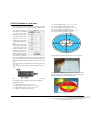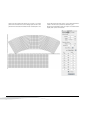
1
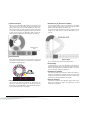
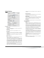
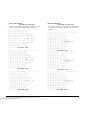
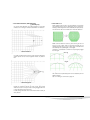
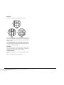
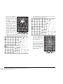
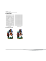
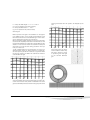
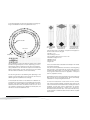
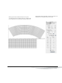
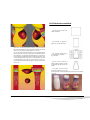
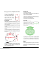
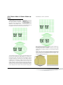
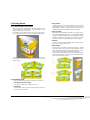
Powerwarp Userguide
FOR
ARTPRO 8.6
Table of Contents
Introduction
7. Drinking Cups
1. Procedure & Conversions
8. Rounded Cardboard Box
1.1 Procedure . . . . . . . . . . . . . . . . . . . . . . . . . . . . . . . 5
1.2 Gridwarp Conversion . . . . . . . . . . . . . . . . . . . . . . . 5
9.1 Grid creation values. . . . . . . . . . . . . . . . . . . . . . . . 30
2. Dialog Box Overview
9.2 Grid Example. . . . . . . . . . . . . . . . . . . . . . . . . . . . . 31
2.1 General . . . . . . . . . . . . . . . . . . . . . . . . . . . . . . . . . 6
2.2 Warp Options. . . . . . . . . . . . . . . . . . . . . . . . . . . . . 6
2.3 Grid Options. . . . . . . . . . . . . . . . . . . . . . . . . . . . . . 8
2.3.1. Grid Options . . . . . . . . . . . . . . . . . . . . . . . . 8
2.3.2. Grid Editing . . . . . . . . . . . . . . . . . . . . . . . . . 8
12
12
12
12
3.2 Printing a grid. . . . . . . . . . . . . . . . . . . . . . . . . . . . 13
3.3 Basic settings. . . . . . . . . . . . . . . . . . . . . . . . . . . .
3.3.1. Density . . . . . . . . . . . . . . . . . . . . . . . . . . .
3.3.2. Height.. . . . . . . . . . . . . . . . . . . . . . . . . . . .
3.3.3. Width . . . . . . . . . . . . . . . . . . . . . . . . . . . . .
3.3.4. Angle. . . . . . . . . . . . . . . . . . . . . . . . . . . . .
3.3.5. Arc / Radius. . . . . . . . . . . . . . . . . . . . . . . .
9.3 Conversion Formulas. . . . . . . . . . . . . . . . . . . . . . . 31
10. Printing on shrink foil
10.1 When to use Sleeve warping . . . . . . . . . . . . . . . . 32
10.2 Design for Shrink Sleeves . . . . . . . . . . . . . . . . . . 32
10.3 Production workflow . . . . . . . . . . . . . . . . . . . . . . 34
3. Grid Creation
3.1 Grid Creation principles . . . . . . . . . . . . . . . . . . . .
3.1.1. Basic grid warping . . . . . . . . . . . . . . . . . . .
3.1.2. Manual grid creation . . . . . . . . . . . . . . . . .
3.1.3. Sleeve grid. . . . . . . . . . . . . . . . . . . . . . . . .
9. Cardboard Cone Cups
13
13
13
13
13
13
4. Blister packs
4.1 Production workflow . . . . . . . . . . . . . . . . . . . . . . 14
4.2 Grid Creation . . . . . . . . . . . . . . . . . . . . . . . . . . . . 14
4.3 Examples . . . . . . . . . . . . . . . . . . . . . . . . . . . . . . . 16
4.3.1. Grid example . . . . . . . . . . . . . . . . . . . . . . . 16
4.3.2. Artwork example . . . . . . . . . . . . . . . . . . . . 16
5. Metal Cups, Cans and Drawn caps
5.1 Production workflow . . . . . . . . . . . . . . . . . . . . . . 17
5.2 Grid creation for round Metal Cups and Drawn caps 17
5.3 Grid Creation for oval cans . . . . . . . . . . . . . . . . . . 20
5.4 Grid Creation for Sardine Cans. . . . . . . . . . . . . . . 21
10.4 Sleeve Mode & Sleeve Mode options. . . . . . . . . . 36
11. 3D View
11.1 Generating a 3D View . . . . . . . . . . . . . . . . . . . . . 39
11.2 3D Settings . . . . . . . . . . . . . . . . . . . . . . . . . . . . .
11.2.1. Close Top/Left . . . . . . . . . . . . . . . . . . . . .
11.2.2. Close Bottom/Right. . . . . . . . . . . . . . . . . .
11.2.3. Rotate 180° . . . . . . . . . . . . . . . . . . . . . . .
11.2.4. Use selection as slices . . . . . . . . . . . . . . .
11.2.5. 3D View . . . . . . . . . . . . . . . . . . . . . . . . . .
40
40
40
40
40
40
11.3 3D View Settings . . . . . . . . . . . . . . . . . . . . . . . . .
11.3.1. Rotate speed . . . . . . . . . . . . . . . . . . . . . .
11.3.2. Real Time Update . . . . . . . . . . . . . . . . . . .
11.3.3. Random Angle . . . . . . . . . . . . . . . . . . . . .
11.3.4. Angles: Ver./Hor . . . . . . . . . . . . . . . . . . . .
11.3.5. Distances: Depth/Height . . . . . . . . . . . . . .
11.3.6. Perspective . . . . . . . . . . . . . . . . . . . . . . . .
11.3.7. Lightings . . . . . . . . . . . . . . . . . . . . . . . . . .
11.3.8. Background . . . . . . . . . . . . . . . . . . . . . . .
11.3.9. 3D View . . . . . . . . . . . . . . . . . . . . . . . . . .
11.3.10. Reset Pos. . . . . . . . . . . . . . . . . . . . . . . .
11.3.11. Export . . . . . . . . . . . . . . . . . . . . . . . . . . .
40
40
40
40
40
41
41
41
41
41
41
41
11.4 Using Slices. . . . . . . . . . . . . . . . . . . . . . . . . . . . .
11.4.1. The Principle of using slices . . . . . . . . . . .
11.4.2. Defining slices . . . . . . . . . . . . . . . . . . . . . .
11.4.3. Spring Mass Models . . . . . . . . . . . . . . . . .
42
42
42
43
6. Flat Ceramic Printing
PowerWarp on ArtPro 8.5
— p. 2 —
12. Appendix
12.1 Grid File Formats. . . . . . . . . . . . . . . . . . . . . . . . . 47
12.2 Definition of the Grid Coordinates . . . . . . . . . . . . 47
12.3 Grid Examples . . . . . . . . . . . . . . . . . . . . . . . . . . 48
12.4 Symmetrical grids in ArtPro . . . . . . . . . . . . . . . . . 50
12.5 Formulas of Link Values . . . . . . . . . . . . . . . . . . . 51
— p. 3 —
PowerWarp on ArtPro 8.5
Introduction
I. Definition
The Gridwarp module is a powerful and professional utility that
allows technical and free deformation of line-art, text and images.
II. Copyright
Copyright © 1992 - 2008, Artwork Systems N.V. All rights reserved. Artwork Systems, ArtPro, Artworker and ArtPrinter are
trademarks of Artwork Systems N.V.
These notes may not, in whole or in part, be reproduced in any
form, by print, photocopy, microfilm or any other means without prior written consent of Artwork Systems N.V.
III. PowerWarp Requirements
PowerWarp as described in this manual is an additional module of ArtPro. The Contone module or ArtColor module for image editing on pixel level is mandatory for warping non flat color
objects.
IV. About this User Guide
This user guide is an addition to the ArtPro manual and describes an optional module of ArtPro. The user guide is meant
to be used as both a manual with a look-up information guide
and a tutorial.
The reader should have a basic knowledge of ArtPro and ArtColor.
PowerWarp on ArtPro 8.6
— p. 4 —
1. Procedure & Conversions
1.1 Procedure
Elements located on a source grid are transposed onto a destination grid, keeping into account the distortion given to one of
these grids.
• Practically :
Once a grid has been created (see further) it is a highly productive tool which warps or deforms in 4 quick steps:
• select those items that have to be warped
• position the ruler at the top left of this selection
• load the grid file with the Load Grid button
• click the Warp button in the Grid Warp dialog box.
— p. 5 —
1.2 Gridwarp Conversion
The difference with Path Warp is not only the use of a grid i.o.
a path, but there are a lot more possibilities in gridwarp. Along
with paths you can also warp text, gradations and pictures.
Linear vertical, horizontal and circular gradations will be converted to internal images to enable the deformation.
A multistep gradation will also be converted to CT automatically, but you have the option to keep a multistep gradation in the
final result by warping the shape of the multistep and reapplying the warped shape to the multistep object.
Before Warping
After Warping
flat color/lineart
flat color/lineart
vertical gradation
internal CT
horizontal gradation
internal CT
circular gradation
internal CT
multistep gradation
internal CT
Placed image
internal CT
Mapped image
internal CT
internal CT
internal CT
Text
Vectorised text
PowerWarp on ArtPro 8.6
2. Dialog Box Overview
2.1 General
• Warp
Clicking this button will start to warp the selected objects
from the source grid to the destination grid.
This same button is used to perform a reverse warp: check
the Reverse Warp checkbox and select the objects that are
located on the destination grid to warp them back to the
source grid. See also • Reverse Warp on page 6.
Keep in mind that loading a grid with the x2 or x4 option can
give unexpected results if the selected grid file is not a quadrant of the final grid you want to achieve.
• Current
The name of the loaded grid file will be displayed in the Grid
Warp dialog box after Current:
2.2 Warp Options
• Load Grid
If a grid was saved before, it can be loaded after clicking this
button. The source grid will be positioned in the lower right
corner of the ruler.
After loading a grid file you can start editing the grid, but the
grid file remains untouched, unless you save and overwrite it.
• Reverse Warp
will warp the selected paths from destination grid back to
source grid. See also • Warp on page 6.
• Full - 1/2 - 1/4 - x2 - x4
When set to “Full”, the grid will be read as specified in the grid
file. It will also use the “quadrant” parameter specified in the
file. See also 12.1 Grid File Formats on page 47.
The main factor to determine the outcome of partially (1/2 or
1/4) loading a grid, is the number of segments in the original
grid. If the number of segments is a multiple of 4 (or 2), a
quarter (or half) of the segments of that grid will be loaded.
In the other cases, the resulting number of segments will be
1/4 (or 1/2) of the original, and an extra segment is added,
created in such a way that the width of the saved source grid
will be exactly 1/4 (or 1/2) of the original source grid.
When multiplying the loaded grid, the grid as defined in the
file will be treated as a quadrant of a grid with 2 (x2) or 4 (x4)
quadrants. The grid will be mirrored vertically (x2) or both vertically and horizontally (x4).
PowerWarp on ArtPro 8.6
Keep in mind that this option also influences the 3D view.
See 11. 3D View on page 39 for more information.
• Keep Original
The original paths are kept, along with the warped result.
— p. 6 —
• Resolution for CT (default set at 300 dpi)
• Extend Source Grid
Allows you to have objects fall outside the source grid to the
right. The part of the job outside the grid will overlap the beginning of the warp, so as to make a perfect join. This possibility will avoid having to split up paths which should lie partly
on one side of the grid at the beginning and partly on the other side, at the end (only for destination grids over 360 degrees and source grids with vertical left and right edges)
For each original image in the source selection, a new image
will be created during warping, using the image resolution
defined in the Resolution for CT field (in dpi).
This option enables the user to boost the resolution for the
images in the warp result in extreme deformation circumstances.
Extend Source
Grid
• Flip Source Grid
If the Flip Source Grid option is on, the original (on the source
grid) will be mirrored vertical and horizontal (i.e. rotated over
180 degrees) before warping.
In this example the resolution for the CT would be set at 600
dpi or more because of the extreme deformation.
• Oversampling
If oversampling is on, the CT’s calculated for the warped vignettes and images will be calculated at a higher resolution,
and then downsampled to the defined resolution. This will result in a smoother image and gradations.
• Resolution for Gradients
This parameter defines the resolution used when images (internal CTs) are created for gradients during warping. Internal
images are created when vertical, horizontal or circular gradations and multistep gradations are warped.
• Noise for Gradients
• Sleeve Mode
will enhance the warping functionality for sleeves (see 10.
Printing on shrink foil on page 32). It will also force the 3D
functionality to use Sleeve Mode. The other Sleeve Mode options are also discussed in that chapter.
— p. 7 —
The Noise for Gradients option allows to apply noise to a gradation when creating an image. This noise allows to avoid
banding in the gradation.
PowerWarp on ArtPro 8.6
2.3 Grid Options
metric. See 12.4 Symmetrical grids in ArtPro on page 50 for
more info.
• Save Grid in Inch
Forces the Grid file to be saved with Inch as unit instead of
mm (see 12.1 Grid File Formats on page 47).
• Grid to Paths
Will make an exact replica of the grid as paths. The paths will
be put in a separate layer called ‘Grid’. If a stroke is created
based on these paths, it enables you to print the grid.
• Erase Grid
Will erase the virtual grid; the paths in the ‘Grid’ layer will stay.
2.3.2 Grid Editing
• What ?
2.3.1 Grid Options
• Create Grid
Will open a new dialog box for the creation of grids. (see 3.
Grid Creation on page 12)
• Show Grid
this is a toggle to switch the grid visualization on or off.
• Save Grid
Enables you to save a grid you have created or changed as
an ASCII text file. This is the grid format which can be loaded
afterwards.
Details about the structure of such grid file can be found in
the appendix.
• Full - 1/2 - 1/4
If a grid is saved, you can choose whether the grid should be
saved completely (“Full”), or partially (1/2 or 1/4).
The main factor to determine the outcome of partially saving
a grid, is the number of segments in the original grid. If the
number of segments is a multiple of 4 (or 2), a quarter (or half)
of the segments of that grid will be saved. In the other cases,
the resulting number of segments will be 1/4 (or 1/2) of the
original, and an extra segment is added, created in such a
way that the width of the saved source grid will be exactly 1/
4 (or 1/2) of the original source grid.
However, if you know that you will be working with Partial
grids in ArtPro, you should make sure that your grid is sym-
PowerWarp on ArtPro 8.6
A tool to edit either the source or destination grid on a manual basis. In the Which pop up menu you have the choice between Source Grid and Destination grid. Only one can be
edited at the time. Click the Modify Tool button and use this
new cursor to select the grid points that have to be moved.
• If you need to move one point at the time, it is very easy :
by clicking on an unselected point you can drag it to the desired location without having to click a second time.
• Several points can be moved by clicking and dragging a
rectangle that covers those points, or use the shift key and
click to select multiple points.
To move: click on one of the selected points and drag in the
desired direction. The way several moving points behave
during the movement depends on the How and Locality settings in the Modify Grid dialog box. These options are described next.
In case of a misplacement you can always return one step by
clicking the Undo button in the Modify grid dialog box.
• Which
The Which setting allows to define if you want to modify the
Source grid or the Destination grid.
— p. 8 —
• How: Same Direction
[x] Locality: 10%, 50%, 90%
25 points were selected; the original location of the point
clicked on is marked #, the destination is marked o.
• How: Same Waypoint
[x] Locality: 10%, 50%, 90%
25 points were selected; the original location of the point being clicked on for moving is marked #, the destination is
marked o.
[x] Locality : 10%
[x] Locality : 10%
[x] Locality : 50%
[x] Locality : 90%
— p. 9 —
[x] Locality : 50%
[x] Locality : 90%
PowerWarp on ArtPro 8.6
• How: Same Direction, Same Waypoint
[ ] Locality: any
25 points were selected; the original location of the point
clicked on for moving is marked #, destination is marked o.
Same Direction
• Fit to Path H / V
When applying this function, the grid selected in the Which
popup dialog (source grid or destination grid) is scaled horizontally (or Vertically) to fit into the selected path (see picture).
The size of the cells is not influenced in the other direction.
Make sure that after the function, points of the grid do not
end up on top of each other, as the warp module can not
handle grid points lying on top of each other. Grid elements
should always be quadrangles, not triangles.
Therefore it is advisable to make the shape slightly bigger
than the grid.
Wrong
If Locality is switched off and How is set to Same Waypoint,
several points can be moved together without any side effect.
Right
• Compensate
will create the compensated path for the selected path for
Sleeve warping.
See 10. Printing on shrink foil on page 32.
Same Waypoint
The lower the Locality percentage with Same Waypoint, the
bigger the movement will be of most points. Grid points
which are closer to the point that is being dragged with the
cursor will always be moved more.
Locality being switched off is more extreme than Locality of
zero percent
PowerWarp on ArtPro 8.6
— p. 10 —
• Distortion
Defines the Distortion Percentage for Fit to Path V.
The distortion indicates the ratio between the vertical size of
the lower grid element and the vertical size of the upper grid
element. The vertical size of the elements in between will be
equally spread.
In the example above, you can see that at a distortion of
100%, all grid elements have the same vertical size. At 50%,
the topmost element is half as high as the bottom element.
At 200%, it is double the height.
• Undo Grid
This will undo the last changes made to the Grid. Keep in
mind that the regular Undo function does not affect grid
changes. There is only one Undo Grid possible.
• Compensate Color
Allows to compensate for color changes caused by shrinking.
See 10. Printing on shrink foil on page 32.
— p. 11 —
PowerWarp on ArtPro 8.6
3. Grid Creation
3.1 Grid Creation principles
There are basically 3 types of grid creation. The flow chart underneath shows the distinction between the 3.
First of all you have to consider if and how the object will be
physically deformed later on in the production process.
Based on this knowledge you can understand what kind of deformation you need and what grid, source or destination, that
should be deformed. For every production technique there will
be a different solution.
• Cardboard Cone Cups
Based on a circular grid. See 9. Cardboard Cone Cups on
page 30
3.1.2 Manual grid creation
If there is deformation after printing (other than shrinking
sleeves), the grid needs manual adjustments.
To create the source and destination grid you use the basic
measurements of the object. This grid should be printed and
deformed.
The part of the object with the grid printed on, should then be
made as flat as possible to be able to scan it. Place the
scanned picture in an ArtPro document where you remake the
original grid as exact as possible on top of the placed scan.
Then you can see that (slight) adjustments have to be made to
the grid. These adjustments should be done manually with the
Modify Grid tool.
• Blister Packs
Based on a rectangular grid.
See 4. Blister packs on page 14
• Metal cups, cans and drawn caps
Based on a round, elliptical or complex grid.
See 5. Metal Cups, Cans and Drawn caps on page 17
3.1.3 Sleeve grid
When the artwork is not deformed after printing, you can use
the basic grids generated by ArtPro automatically, which are
not material or machine dependent. You have the choice between Rectangular, Circular, Complex and Conic grids.
To create this source and destination grid you only need the
basic measurements of the object.
For Sleeves, ArtPro provides a more automatic way to create
the grid, as for most modern sleeve shrinking methods, we can
assume a regular deformation, and therefor use mathematical
approximations.
Some shrinking methods, like using steam, will shrink the
sleeve equally all over the bottle, while other methods like hot
air, can generate a bigger shrinking on the side(s) where the air
is blown onto the bottle. In this latter case, the mathematical
result will be less accurate.
• Flat Ceramic printing
• Shrink foil or sleeves
3.1.1 Basic grid warping
For Ceramic plates and dishes. Based on a round grid.
See 6. Flat Ceramic Printing on page 22
Based on a rectangular grid, using “Sleeve Mode”.
See 10. Printing on shrink foil on page 32
• Drinking cups
Based on a complex or round grid. See 7. Drinking Cups on
page 25
• Rounded Cardboard Boxes
Based on a complex grid. See 8. Rounded Cardboard Box
on page 27
PowerWarp on ArtPro 8.6
— p. 12 —
3.2 Printing a grid
To print a grid :
• Load a grid or create one
• click the Grid To Paths button in the Gridwarp dialog
• While the paths are still selected, use the Stroke function
(q - x - t) and the Paint Style (q - i) to define the line thickness and color.
• Print the job (q - p)
3.3 Basic settings
Some basic settings will be explained more into detail and in
general first, because they will be available in the Create Grid
dialog boxes of almost any grid type:
3.3.4 Angle.
For circular grids, or circular parts of complex grids, the circular
part is defined by the angle and the Arc, or the Angle and the
Radius.
3.3.5 Arc / Radius
When defining a circular grid,
or a circular part of a complex
grid, you can choose to define it by Arc length, or by Radius. This will always be the
Inner Radius or the Inner Arc
length, uninfluenced by the
Baseline At setting.
3.3.1 Density
the value from this field defines the width and height of a single
cell from the grid. Such a square shaped, single cell is the basic
part of a grid and defines four points in the source grid that correspond with four points in the destination grid. Based on these
four points, the item within the cell from the source grid will be
deformed, stretched or shrunk, when warped onto the destination grid.
The density has an influence on the speed of the warp calculation. A Density ranging from 3mm to 5mm is advisable for most
grids. Circular grids might need a lower density value if the segments of the circular parts are not smooth enough.
The Width and Height of the grid should be big enough to cover
the object, maybe even with a surplus of a few cells on certain
sides.
3.3.2 Height.
Measure the Height. Therefor do not measure the vertical
height if the object would have a sloping side, but place the ruler on the object itself for measuring the slope side.
3.3.3 Width
The value that has to be filled in for Width is not always exactly
the width, but depending on the object it could be the value
from the circumference or inner circle on the technical drawing.
Since the basic element of the grid is one cell, it is recommended to fill in values for both Height and Width which are dividable
by the Density value. Otherwise the grid cells will be adapted in
size automatically when the grid is created and this could be
annoying for measuring afterwards.
For sleeves, the grid should be the size of the sleeve, without
the overlap.
— p. 13 —
PowerWarp on ArtPro 8.6
4. Blister packs
4.1 Production workflow
- print the job on the flat substrate (plastic)
- the substrate is then shaped (heated, stretched into a shape)
- this gives the final result where the image should look normal
(not affected by the shape of the object)
With the warp module we will have to invert the deformation
caused by the machine that is stretching the substrate:
4.2 Grid Creation
First a basic grid has to be
made which consists of a rectangular source and destination grid. Therefor click on the
Create Grid button in the Grid
Warp dialog box. Then click
the first icon: Rectangular.
Three values have to be filled
in:
• Density: 3 mm
• Height: the example object is about 50 mm high, but we’ll
fill in 85 mm.
• Width: the example object is about 35 mm wide, but we’ll
fill in 50 mm.
Rectangular will automatically make a rectangular source grid
and a rectangular destination grid which are exactly the same.
Save the grid.
Print the grid on the substrate.
Deform the substrate in exactly the same way as it would be
done during production. Now you have your master blister
pack.
This explains why the grid we should change, is the source
grid, while the destination grid will have to remain unchanged,
rectangular.
PowerWarp on ArtPro 8.6
— p. 14 —
This is a small, shaped object that can be placed on a
flatbed scanner to get a digital image from the deformed grid.
This image will be used for
the manual deformation
which will be explained in
detail more next.
When the scan is placed in a
new document, load the
grid that was printed for deformation. Position the scan
in a way that as many unwarped points as possible
are lying on top of their corresponding points on the
scan.
(note for the pictures underneath : 50% black is the TIFF of the
scanned grid, the small 100% black lines are the grid lines)
Use the Modify Grid tool for moving every point to its new position, based on the underlying scan.
Now you will be able to use
this grid by loading it whenever you need to warp this
type of blister pack.
Open a job containing all
artwork, position the ruler at
the top left of the selected
artwork, click the Warp button in the Grid Warp dialog
box to start warping the selected items towards the
destination grid.
— p. 15 —
PowerWarp on ArtPro 8.6
4.3 Examples
4.3.1 Grid example
Source Grid
Destination Grid
4.3.2 Artwork example
Source
PowerWarp on ArtPro 8.6
Destination
— p. 16 —
5. Metal Cups, Cans and Drawn caps
The technique explained below is similar to the blister pack
one.
• Angle: 360 degrees.
5.1 Production workflow
- print the job on the flat substrate (metal)
- the substrate is then shaped (drawn into shape)
- this gives the final result where the image should look normal
(not affected by the shape of the object)
With the warp module we will have to invert the deformation
caused by the machine that is stretching the substrate.
5.2 Grid creation for round Metal Cups
and Drawn caps
First create a basic grid
with Create Grid, Circular.
The source grid will be
rectangular and the destination grid will be rounded.
• Density: 3 mm to 5 mm
• Height (source and destination): height of the can
+ 20%.
Adding 10% on both sides
of the height is necessary
to make sure that the deformed, printed grid of the
master cup would not
cover the side of the cup
completely. There will be
quite a big overlap, but by
adding two horizontal reference lines where the ideal top and bottom of the cup height
should be, you will be able to position the job correctly afterwards by putting it in between these two reference lines on the
source grid.
• Radius: radius of bottom flat part of the can - 10%.
— p. 17 —
Now check the Link Values checkbox. This will calculate the
corresponding width (explained in the technical appendix).
Calculated example:
h = original height of the cup; e.g. 100 mm
r = original radius of the cup; e.g. 50 mm
a = addition to the height of about 10%
PowerWarp on ArtPro 8.6
H = newly calculated height = h + a + a = 120% h
e.g. 120 mm (based on the previous values)
R = newly calculated radius = r - 10% h
e.g. 40 mm (based on the previous values)
source grid towards their new position, as displayed by the
scan.
Save the grid.
Make a printout of this grid on the substrate. Do not forget to
put a reference point* on the circular grid somewhere on the
left horizontal line of the circular destination grid. This is necessary for positioning the grid on the scan later on.
Be sure the grid is properly centered, so that the circular reference lines are completely horizontal on the deformed can and
that the vertical reference corresponds to a fixed reference zero
direction on the machine. Deform the substrate in exactly the
same way as it would be done during production. Now you
have your master can.
To get a digital image from the printed grid, you have to cut
away the bottom of the cup. What ’s left now is a metal cylinder. Cut open the cylinder with a vertical cut, right there where
the grid got marked*, and flatten the substrate to be able to
scan the deformed grid.
Here you can see the reference marks, which are highly
recommended to create. They
will come in handy if it comes
to positioning the virtual grid
on the scanned deformed
grid.
This image is used for the deformation of the source grid as
done for the blister pack: load the original grid in an ArtPro document. Place the scan and position it underneath the source
grid. Use the Modify Grid tool and start moving the points of the
Above: the grid printed to create the master can.
PowerWarp on ArtPro 8.6
— p. 18 —
Below: the final grid with the adapted source grid.
Notice that especially the vertical adjustments are of importance because of the can drawing technique. Horizontal
changes are never to be registered: the can stretches in the
vertical direction only. The horizontal deviation is negligible.
Additional Examples :
1. Printed plates, ready for drawing the cans out of
2. Plate with cup ; barcode on bottom
Below: output of the grid was made on film, then transmitted
to the metal plate. From this plate a master cup can be drawn.
3. Plate with cup ; barcode on side. Undistorted picture and
text on the bottom
The distortion information must be digitized by
adapting the virtual
source grid. If this would
not be done, the images
and text on the sides of
the cup would be waving. See picture at the
right.
— p. 19 —
PowerWarp on ArtPro 8.6
5.3 Grid Creation for oval cans
Grid Creation for oval cans is exactly the same as for round
cans, but instead of a circular grid, we’re using an elliptical grid.
First create a basic grid
with Create Grid, Elliptical.
The source grid will be
rectangular and the destination grid will be rounded.
• Density: 3 mm to 5 mm
• Height (source and destination): height of the can +
20%.
Adding 10% on both sides
of the height is necessary
to make sure that the deformed, printed grid of the
master cup would not cover the side of the cup completely.There will be quite a
big overlap, but by adding
two horizontal reference
lines where the ideal top and bottom of the cup height should
be, you will be able to position the job correctly afterwards by
putting it in between these two reference lines on the source
grid.
• Horizontal Radius: horizontal radius of bottom flat part of the
can - 10%.
• Vertical Radius: vertical radius of bottom flat part of the can 10%.
H = newly calculated height = h + a + a = 120% h
e.g. 120 mm (based on the previous values)
Rv = newly calculated vertical radius = rv - 10% h
e.g. 40 mm (based on the previous values)
Rh = newly calculated horizontal radius = rh - 10% h
e.g. 65 mm (based on the previous values)
The following steps are exactly the same as for a round grid.
above: output of the grid was made on film, then transmitted
to the metal plate. From this plate a master cup can be drawn.
Below : an example of a can and the flat plate.
Now check the Link Values checkbox. This will calculate the
corresponding width (explained in the technical appendix).
Calculated example:
h = original height of the cup; e.g. 100 mm
rv = original vertical radius of the cup; e.g. 50 mm
rh= original vertical radius of the cup; e.g. 75 mm
a = addition to the height of about 10%
PowerWarp on ArtPro 8.6
— p. 20 —
5.4 Grid Creation for Sardine Cans
For this, you can use the Complex grid just like the Circular
grids. The only difference is that the operator has more options
for the creation of the basic ArtPro grid, which now can be not
only round but oval shaped too.
First create a basic grid with Create Grid, Complex. The source
grid will be rectangular and the destination grid will be a combination of rounded parts and straight parts:
• Density: 3 mm to 5 mm
• Height (source and destination): height of the can + 10%.
• Radius: radius of bottom flat part of the can - 10%.
• Length: for the straight parts
• Angle: all 4 angles should be 90 degrees.
Now check the Link Values checkbox. This will
calculate the corresponding width (explained in the
technical appendix).
Save the grid.
Do not forget to put a reference point (see also
page 14) on the circular
grid somewhere on the left
horizontal line of the circular destination grid. This is necessary
for positioning the grid on the scan later on. Then print the grid
on the substrate.
Deform the substrate in exactly the same way as it would be
done during production. Now you have your master can.
This is an object that can not be placed on a flatbed scanner
to get a digital image from the deformed grid. To get this image
you have to cut away the bottom of the cup. What’s left now is
a metal cylinder. Cut open the cylinder with a vertical cut, right
there where the grid got marked*, and flatten the substrate. Put
this on the scanner for scanning the deformed grid. Save the
scan as a TIFF file to be able to use it at its full resolution in ArtPro as a placed picture. Go to Edit > Preferences > Display :
Picture Display Resolution, to set the right resolution and then
map the TIFF.
This image will be used for the manual deformation of the
source grid similar to the way the grid of the blister pack was
edited: load the original grid in an ArtPro document. Place the
scan in the same document and position it underneath the
source grid. Use the Grid Editing tool and start moving the
— p. 21 —
points of the source grid towards their new position, as displayed by the scan.
Above: the basic grid as printed
first on the substrate for the formation of the master can.
On the right you can see the parameters for this basic grid
After using the modify tool to reposition the grid points according
to their position on the scan, the
final result is created and looks
like this:
PowerWarp on ArtPro 8.6
6. Flat Ceramic Printing
This technique is also
based on the Circular grid.
The special thing about
ceramic warping is that
the resulting warp will not
have any further distortion. The warped result in
ArtPro will be printed on
the ceramic surface. No
eye catching deformation
will occur during or after
printing.
Production workflow:
- the design is warped
- the design is printed on
an almost flat substrate
(ceramic dish)
With the warp module we
will have to get the design into the right shape.
Imagine we have a flat piece of artwork, created by a designer,
and we want to warp this design on a circular plate. The plate
and the design have the following dimensions :
• Source Height (design): 40 mm
• Source Width (design): 70 mm
• Radius (inner radius of the plate): 80mm
• Destination Height (outer radius = 120 mm): 40 mm
- the elements which are very close to the inner circumference
have no or minimal distortion, and are the way we want them
to be.
- the elements close to the outer circumference are stretched
and do not look like the original design anymore.
- when trying to copy-rotate the resulting warp a number of
times, to fill the complete plate, we find out that the beginning
and end do not match: the elements overlap with an unacceptable deviation.
The solution to all this is the use of the Baseline at parameter.It
defines what height the grid baseline should be set at. This is
the section of the grid where the least amount of deformation
will occur or where the warping is not extreme in such a way
that the result would be misformed and unacceptable.
The value of Baseline at: is a percentage of the height value,
where 100% is the top of the source grid and 0% is the bottom
of the source grid, as shown below.
100%
50%
0%
100%
50%
0%
40mm
We also see that when changing this parameter, the width of
the source grid is changing too. This is easy to understand as
objects on the outside of the circle having the same length as
the original objects at Baseline 100%, the width of the source
grid will be the length of the outer circumference.
70mm
If a normal circular grid is used, and we warp one single design
element, we get the result shown later on. We notice the following three things:
PowerWarp on ArtPro 8.6
— p. 22 —
In the example below we used one grid without changing anything to the Baseline at which is by default set at 0%.
Objects are OK
No match
Stretched
Using a Baseline at 100% will make the objects at the outside
look like the original objects, but then, objects lying on the inside will have maximum distortion (in this case a compression).
Using a Baseline at 0% will make the objects at the inside look
like the original objects, but then, objects lying on the outside
will have maximum distortion (in this case a stretch).
It is becoming obvious to use different grids: depending on the
position of the original object on the source grid, we will use a
different grid with a baseline set accordingly
In this example the artwork can be divided into 3 different horizontal parts, so that each part can be warped with minimal deformation. This means 3 different grids are needed: one with a
baseline set at about 25%, the others at 50% and 75%. If it is
not possible to divide the job in different horizontal parts, we
will have to choose the baseline at 50%.
— p. 23 —
The source grid
with the original
items.
The result when
The result when
using a grid with
using a grid with
baseline at 0%
baseline at 100%
Take the lower part of the design, the part that will appear on
the inner side of the circular grid.
• Density: 5 mm
• Source Height: 40 mm
• Source Width: leave this at 0 mm for now
• Destination Height 40 mm
• Baseline at: 0%
• Radius: 80 mm
• Angle 360º
The source width will be calculated automatically if Link Values
is checked: 502.65mm
This part must be repeated around the circle, so that beginning
and end match. This means that the source width must be a
multiple of the design width. In our example, the multiples of 70
mm lying near to 502.65 are 490 mm (repetition: 7 times) and
560 mm (repetition: 8 times).
As Baseline is linked to the source Width, this means that when
filling in those new source Width values, ArtPro automatically
calculates the corresponding Baseline value.
For 490 mm this becomes -5.03% and for 560 mm, 22.82%.
If we choose the first possibility, the design lying closer to the
inner circle will have minimal deformation, choosing the second
possibility, we will have minimum deformation at 22.82%,
meaning at radius distance 80 + 22.82% x 40 = 89.128 mm.
We will choose the second value. This means that after warping we will have to rotate the result 8 times to fill the complete
circular plate.
PowerWarp on ArtPro 8.6
Rotate 10x over
360/10 degrees
Rotate 8x over
380/8 degrees
Rotate 7x over
360/7 degrees
Using the same method, we calculate and generate the grid for
the other two parts : the middle part and the upper part. For
the middle part, we would like to have the Baseline at around
50%. Filling in this value gives us a source width of 628.32 mm.
Changing this to 630 mm (multiple of 70) gives us a new Baseline at 50.67%, which is very close to what we want. For the
last part, we want a value around 90%, this gives us a width of
728.85 mm. The best multiple of 70 here is 700 mm giving a
new Baseline at 78.52%.
When the grids are created, load them one by one, select the
right part of the design on the source grid and warp. Place the
Ruler in the middle of the destination grid and rotate the
warped result as many times to fill the complete circular form.
Before loading the second grid, make sure that the ruler is
placed on the right position (with center on the top left corner
of the source grid.
PowerWarp on ArtPro 8.6
— p. 24 —
7. Drinking Cups
There is more than one technique for printing drinking cups. It
mostly depends on the material that is being used for the creation of the cups: cardboard which is printed flat and is folded
afterwards into the right shape, and plastic cups which are being printed after the cups are shaped. This last technique is
done by printing all colors on one rubber sloping block which
is located in the printing system. The cups are then rolled
against this rubber block letting the ink being transferred upon
the plastic surface.
First create a basic grid with Create Grid, Conic.
The source grid will be rectangular and the destination grid will
be a segment of a rounded grid:
• Density: 3 mm to 5 mm
• Height: do not measure the vertical height of the object, but
place the ruler on the object itself for measuring the sloping
side.
• Larger diameter: top diameter of the cup.
• Smaller diameter: bottom diameter of the cup.
The cardboard drinking cup workflow is explained in more detail below.
Production workflow:
- print the job on the flat substrate (cardboard)
- the substrate is then shaped (folded into shape)
- this gives the final result where the image should look normal
(not affected by the shape of the object)
No stretching or shrinking of the substrate occurs during this
procedure: the warp module is used to get the design in the
right shape of the unfolded object.
— p. 25 —
PowerWarp on ArtPro 8.6
Save the grid.
The grid file is ready to use right away. Since there is no stretch
or shrink deformation of the substrate, no additional changes
should be made to the grid.
Source Grid
Open a job containing all artwork, position the ruler at the top
left of the selected artwork, click the Warp button in the Grid
Warp dialog box to start warping the selected items towards
the destination grid.
Destination Grid
PowerWarp on ArtPro 8.6
— p. 26 —
8. Rounded Cardboard Box
The Complex grid option can
be used for these kinds of
warping.
Just like the ceramics the resulting warp will not have any
further
distortion.
The
warped result in ArtPro will
be printed on the cardboard
surface. No eye catching deformation will occur during or
after printing.
Production workflow:
- print the job on the flat substrate (cardboard)
- the substrate is then
shaped (folded into shape)
- this gives the final result
where the image should look
normal (not affected by the
shape of the object)
No stretching or shrinking of
the substrate occurs during
this whole procedure: the
warp module is used to get
the design in the right shape
of the unfolded object.
Create a grid with Create Grid, Complex.
The source grid will be rectangular and the destination grid will
be a combination of rounded parts and straight parts.
• Density: 3 mm to 5 mm
• Source Height: height of the box. Do not measure the straight
vertical height but the sloping height.
Depending on the type of box, the following options are not
filled in completely. Most common will be a rectangular box
with rounded corners.
This means there are 8 parts in the destination grid, e.g.:
• straight (left):
Length:
60 mm Angle: 0°
• rounded:
Radius: 100 mm Angle: 15°
• straight (top):
Length:
20 mm Angle: 0°
• rounded:
Radius: 100 mm Angle: 15°
• straight (right):
Length:
60 mm Angle: 0°
• rounded:
Radius: 100 mm Angle: 15°
• straight (bottom):
Length:
20 mm Angle: 0°
• rounded:
Radius: 100 mm Angle: 15°
Use Radius for a rounded part of the box. The Angle can not
be zero. Use Length of a straight part of the box. In that case,
the Angle must be zero.
In other words: you can not combine Length and Angle for defining a rounded part of the grid.
Now check the Link Values checkbox. This will calculate the
corresponding width (explained in the appendix : see 12. Appendix on page 47).
Save the grid. The grid file is ready to use right away. Since
there is no stretch or shrink deformation of the substrate, no
additional changes should be made to the grid.
— p. 27 —
PowerWarp on ArtPro 8.6
Below a grid that was created that exists out of 8 parts:
4 rounded parts for the rounded corners and 4 straight parts
for the side panels which are located in between those round-
PowerWarp on ArtPro 8.6
ed parts.Notice that the destination grid with only 8 parts is not
centered and is not equally built up on both sides
— p. 28 —
Here a grid was created that exists out of 9 parts: 4 rounded
parts for the rounded corners and 5 straight parts for the 4 side
panels which are located in between those rounded parts. One
— p. 29 —
of the side panels has been split up in two half side panels located on the two outer parts of the destination grid.
Notice that the destination grid with 9 parts is centered and is
equally built up around the center.
PowerWarp on ArtPro 8.6
9. Cardboard Cone Cups
Cardboard Cone Cups
can be warped using a
circular grid
Just like the ceramics
the resulting warp will
not have any further distortion. The warped result in ArtPro will be
printed on the cardboard surface. No eye
catching deformation
will occur during or after
printing.
One of the most important things to keep in
mind when creating a
grid for Cone Cup
warping, is that the gridwarp module can only
handle quadrangle grid
elements. Therefor, the
bottom of the grid will be stripped, to avoid the creation of triangular grid elements. However, this will not influence the final
result, if the user extends the artwork downwards.
The Height used for the grid (Height) will be the length of the
side of the cone cup (H) minus the length of the stripped part (h)
9.1 Grid creation values
All values necessary for the creation of the correct grid, is
based on only 2 parameters : the length of the side of the cone
cup (H), and the angle ( α ). If any other pair of values is given,
these can be used to calculate the side of the cone and the angle. For some conversion formulas, see 9.3 on page 31.
• Density
It is highly recommended to
use 0.5 mm.
• Source Height
As explained above, the
Height for the grid will be the
total height of the cup minus
the stripped part.
So Height = H - h
é
The height of the stripped
part (h) is defined by the
length of the Arc (see below)
and the Angle, using the following formula:
× Density × 180h = 40
----------------------------------------------Angle × π
or in another form :
Density × 2.292h = --------------------------------------Angle
• Source Width
The value for width does not matter, as it has no influence on
the grid
• Destination Height
The same as the Source Height
• Baseline At
should be set at 100% to start (see also 6. Flat Ceramic Printing on page 22)
• Arc/Angle
Arc = 40 x Density
the Angle is the angle ( α )
• Link Values
should be OFF
PowerWarp on ArtPro 8.6
— p. 30 —
9.2 Grid Example
the result of unwrapping the cone cup) or in a 3D model (bottom drawing)
Here are some formula’s that can be used:
• Formulas for the angle
A 180
α = ---- × --------H
π
The example above shows a grid for cone cups. Notice that the
graphic design (shown in magenta) extends the source grid,
generating the tip in the warped version. When creating a 3D
preview, this will result in a nice cone (see previous page).
9.3 Conversion Formulas
When receiving the information about the cone (mostly from
the CAD department), you will not always receive the information you need.
First of all, you have to get only the dimensions for the printed
part, excluding all glue strips, bleed, etc.
Next, it can be possible that you need to recalculate the desired angle and height from other dimensions. The dimensions
can be represented in a flat 2D model (top drawing, showing
— p. 31 —
D
α = ---- × 180
H
• Formulas for H
L H = ----------cos β
--2
H =
2
D
L + -----4
2
A 180
H = --- × --------α
π
PowerWarp on ArtPro 8.6
10. Printing on shrink foil
10.1 When to use Sleeve warping
The method for shrink sleeves is only valid for circular, symetric
bottles. It is based on the assumption that the shrinking is done
equally all around the bottle. As explained in 3.1.3 Sleeve grid
on page 12, this can depend on the shrinking method.
For non circular but symetric bottles, the same method as for
circular bottles can be used, but the accuracy can not be guaranteed. Again, it will work if the shrinking is equal all around the
bottle, but for non circular shapes this is less obvious.
For non circular, non symetric shapes, it is not advised to use
sleeve warping, as the result would be unpredictable
distorted to a rectangular sleeve, which, after shrinking onto
the bottle, will have the original size of the design.
The first step is to calculate the jacket of the
bottle, based on the heights and diameters,
and adapt the design to this shape. At the
right, you see a drawing of the shape of the
bottle. Next the shape of the jacket (created
using the Compensate function, see further),
with the graphics applied on it.
10.2 Design for Shrink Sleeves
• Why compensate graphics for sleeves
A small example will illustrate why pre-press specialists must
pre-compensate for shrink. Let’s imagine we will print a
round apple on a sleeve of a bottle of apple juice. When the
apple is positioned on the sleeve where the shrink is relatively
small e.g. in the middle, the apple will retain its round shape
(more or less). When you print the apple somewhere on the
top of the bottle - where the shrink is much bigger - the apple
will shrink differently in different directions depending on the
shape of the bottle and the apple will become more eggshaped. Anyone can understand that if you compensate for
this distortion, that is when you print an egg-shaped apple so
that after shrink it becomes round again, the sleeve will look
much better.
without distortion
Next is the warped design on a rectangular shape.
with distortion
• The Design:
From the very start of designing, the designer should take in
account the surface of the bottle the sleeve is designed for.
Regardless of the shrinking, the surface of the bottle is much
smaller in the bottle neck. Therefor, the surface to be designed for should be smaller in the bottle neck area.
This design, shaped like the jacket of the bottle, should be
PowerWarp on ArtPro 8.6
— p. 32 —
After warping, this gives the result as drawn in step 1 but attached to the bottle.
It is obvious that in the bottle neck area, the printable surface
is smaller. Fewer design elements can be placed in that area.
Also note that, as the design is not rectangular, this can limit
the possibilities to use background images. This can however be avoided by not compensating the background image,
and place it undistorted on the sleeve, resulting in a distorted
image after shrink.
• Compensate or don’t compensate ?
When you create a design for a sleeve, it would be fantastic
if the designers could define which elements would need to
be compensated for distortion and which wouldn’t, or put
differently which elements are superior or inferior to the design. This would guarantee your design being produced as
you had it in mind and it would make life for the pre-press departments much easier.
Often designs include vertical columns (patches) to differentiate important areas like nutrition panels. These column-like
areas make it hard to decide if you would need to compensate or not as this is a matter of personal opinion. The images
underneath give a good example:
on the left hand side the nutrition panel was not compensated for shrink, on the right hand side the panel is compensated correctly.
— p. 33 —
However, in relation with other elements, the well compensated straight panel does not look so perfect any more (see
on the right).
This proves that the decision to compensate or not will eventually depend on your own preference and can change depending on the design itself. Therefore it is important that the
designer make this decision and brief the pre-press about
his/her choices.
PowerWarp on ArtPro 8.6
10.3 Production workflow
- print the job on the flat substrate (shrink foil)
- the substrate is “glued” together into a cylinder shape
Apart from the personal opinion there is of course still the
technical limitation that you cannot print more than the sleeve
width. So your decision might depend on this too.
As you can see on the picture below, the compensated panel
(at the right) will consume a huge part of the sleeve width in
the bottle neck, not because the panel takes up more space,
but because the available surface is smaller at that place. The
uncompensated panel only uses its original width and that
can be beneficial if you want to use the space for more important design elements like the apple or an important brand
name, etc.
- the cylinder shaped foil is
brought around an object
(e.g. a bottle)
- the foil is then shrunk by a
heating device whereby the foil
is automatically set around the
object
- this gives the final result
where the image on the shrunk
foil should look normal (not affected by the shape of the object:
the bottle)
PowerWarp on ArtPro 8.6
— p. 34 —
The warp module is used to invert the deformation caused by
the heating apparatus that is shrinking the substrate. How this
can be done is described step by step :
• 1. Draw the shape
• 2. Compensate
d1
Use Create Grid, Rectangular.
Both the source grid and the destination grid will be rectangular. To define the dimensions of the compensated path,
select it and open the box dialog
d2
d3
heig ht
First a path has to be created, showing the shape of the bottle, based on
the actual height and diameters.
Measure the largest and smallest diameters of the bottle, and the
heights, in order to create the shape
as correct as possible. Create a path
based on the measurements.
• 3. create a grid
d4
Select the path, and click the Compensate button. ArtPro will
create a new shape, based on the selected path.
The width of the new path will be the circumference of the
bottle at the given height, so it will be the width of the original
path, multiplied by pi.
Therefor, Compensate will only work for round bottles ! For
any other shape, the circumferences should be calculated
manually.
The height of the new path will be the length of the side of the
original path, representing the height of the sleeve before
shrinking.
The point most to the left of the original path, will remain unchanged, as this represent the height with the biggest diameter, and thus the point where the sleeve will “attach” to the
bottle first, and the rest of the shrinking will be in correlation
to this point.
• Density: 3 mm to 5 mm
• Height: fill in a value slightly smaller than the measured vertical size of the compensated shape
• Width: for best results, fill in a value slightly smaller than the
horizontal size of the compensated shape.
• 4. Fit to path
Open the Modify Grid dialog.
Position the Compensated path
centered over the source grid, so
that the grid is vertically completely
inside the path.
Make sure “which” is set to “Source Grid”.
Click “Fit to path”.
Do realize that this is the source grid. This means that the
original objects that you want to warp must be positioned
onto this grid and can not fall outside of this source grid!
It is obvious that on the smallest part of the bottle there can
not be as many objects as elsewhere, thus there the source
grid is smaller.
• 5. Warp
As in most cases the sleeve is put over the bottle while this
is standing up, the design might have to be clipped by the
bottom of the original shape, resulting in a blank strip at the
bottom of the bottle after shrinking.
— p. 35 —
Position all the design elements that need to be deformed on
the source grid. Objects that for design reasons do not need
to be warped, can be positioned directly onto the rectangular
destination grid. To warp objects, select them, and click the
Warp button.
PowerWarp on ArtPro 8.6
10.4 Sleeve Mode & Sleeve Mode options
Sleeve Mode, is shown underneath
If Sleeve Mode is off, the warping
is done the same way as for any
other grid. However, for sleeves,
this gives extreme deformation for
elements on the outside of the
source grid, whereas there should be no more deformation as
for objects in the center, since the result will be round.
Best results can be achieved by warping in parts, instead of selecting the whole design and warp it.
By splitting the job up, it is possible to decide for every single
object or group of objects, whether or not it should be warped,
and how.
Keep in mind that in most cases, the design should be limited
by the bottom of the uncompensated shape (see earlier). In the
picture underneath, the printable area is shown in yellow, both
on source and destination grid.
To avoid these excessive warp results, the Sleeve Mode should
be used. When warping with “Sleeve Mode” on, a specific routine to warp is used : The center point of the selection, and the
correlation between the center point of the individual objects,
is warped in the normal way, to define the new position of the
warped objects. The individual objects are first moved to the
center of the grid, warped, and then moved to the earlier calculated position. In this way, all objects will be warped as if they
were on the center of the source grid, retaining their position.
For the example shown above, the result when warping with
PowerWarp on ArtPro 8.6
— p. 36 —
• Outlines = text
By warping it as a single object (i.e. without “Outlines=Text”,
or with “Outline=Text” and “Group=Compound”, if the design element is a group).
When the Sleeve Mode option is on, the selection will be
warped by placing it to the center, warp it and displace it
again. For text, this will be done character by character, to
avoid text blocks being distorted.
Text converted to outlines will be treated as regular objects,
so they will all be warped at one go. This will result in a less
uniform warp for the text. (see example underneath on the
left). If the “Outlines = text” option is on, individual objects
(compounds) will be warped one by one. See the example
underneath on the right.
• Group = Compound
If the “Outlines=Text” option is on, individual objects will be
warped one by one (see above). However, for some objects
(e.g. logos), you would want them to be warped as a single
object. By creating a group of these objects, and switching
on the “Group = Compound” option, Groups will be treated
as a compound, and thus be warped in one single go. See
the example underneath.
Underneath there is an example of the importance of how
warping is calculated depending on the design. As you can
see, when warped as individual objects, the line between the
yellow and red square is no longer parallel.
— p. 37 —
• Group = Selection
The Group = Selection option is to be used when warping in
Nexus. Whereas in ArtPro sleeve warping can be done
based on a selection, the “Group=Selection” option allows
Nexus to warp based on groups. By selecting the objects
you want to be warped together (usually in “bands” of the
original) and making it a group, in combination with the
PowerWarp on ArtPro 8.6
“Group = Selection” option in Nexus, you can get the same
result as selecting and warping in ArtPro.
PowerWarp on ArtPro 8.6
— p. 38 —
11. 3D View
Step & Repeat 3D View, or ArtRender is a module that allows
for the creation of a 3D representation of boxes (folding carton)
and cups (conic shapes). The 3D view for boxes can be found
in the ArtPro manual.
11.1 Generating a 3D View
A 3D View can be generated for cup warps and cylindric objects, including sleeves.
— p. 39 —
When generating a 3D view, the Destination grid is used as
base for the 3D rendering. If the Reverse Warp option is on, the
Source Grid is used instead.
Generating a 3D view with the Sleeve Mode option on, will
make ArtPro to use the Source Grid for the creation of the
shape, and the Destination Grid for the design. This means that
objects placed immediately on the Destination Grid, without
warping, will also be shown on the 3D rendering.
Some examples of 3D Renderings are shown below
PowerWarp on ArtPro 8.6
11.2 3D Settings
11.3 3D View Settings
11.2.1 Close Top/Left
The Close Top/Left option allows to close the top side or left
side of a 3D View.
11.2.2 Close Bottom/Right
The Close Bottom/Right option allows to close the bottom side
or right side of a 3D View. Underneath is an example of a 3D
view using slices (see later) without (left) and with (right) the
Close Bottom option.
11.3.1 Rotate speed
defines horizontal rotation speed
11.3.2 Real Time Update
11.2.3 Rotate 180°
The Rotate 180° option allows to turn the design upside down
before creating the 3D View.
11.2.4 Use selection as slices
For more information on using slices, see 11.4 Using Slices on
page 42.
11.2.5 3D View
Clicking the 3d View button will generate the 3d View based on
the settings of the 3d Box Generation and View Settings dialog.
PowerWarp on ArtPro 8.6
If the Real Time Update checkbox is on, every change in the
ArtPro window will immediately update the bitmap on the 3D
representation. For complex jobs, it is advisable to reduce the
3D bitmap resolution (in the preferences) to reduce calculation
times.
If the option is switched off, the 3D bitmap can be refreshed by
using the shortcut q - , (comma). This will recalculate the 3D
image bitmap.
11.3.3 Random Angle
If the Random Angle option is selected, the 3D representation
will rotate with random angles, showing the box automatically
from different positions.
11.3.4 Angles: Ver./Hor
controls the angle from which the viewer looks at the object, in
both dimensions. The angle can be changed interactively in the
3d view by simply clicking and dragging in the window.
— p. 40 —
11.3.5 Distances: Depth/Height
11.3.11 Export
allows the user to control the distance between the viewer and
the rendered object in both dimensions. The Distance can be
changed interactively in the 3d view window by shift-clicking
and dragging in the window.
11.3.6 Perspective
This slider allows to change the perspective angle, to match
camera lenses ranging from fish-eye to telelense.
11.3.7 Lightings
• Attach :
The light source used for the Diffuse light, can be positioned
in two ways. If the Attach option is on, the light source is attached to the camera. This means, no matter how the object
is rotated, the surfaces closest to the camera will be illuminated.
When switching the Attach option off, the light source position is kept relatively to the object. This means, if the object
is rotated, the light source is rotated as well, so even the unlighted parts of the object can be brought to front.
• Ambient :
Ambient light is light without any source, illuminating the
whole object from every direction. If the Ambient light is high,
shadows will be invisible. The amount of ambient light can be
set using the slider, or by entering a percentage.
• Spot
Spot light is light coming from a specific point, the light
source. When using only Spot light, the parts of the object
that can not be reached by the light source, will appear black
or darker, so shadows will appear. The amount of Spot light
can be set using the slider or by entering a percentage.
11.3.8 Background
You can choose an arbitrary TIFF to be displayed as background. The Tiff should be 1024 x 1024 pixels, or 512 x 512,
or 256 x 256. The path of the current background is shown in
the '3D settings' dialog. Shift-clicking the button will empty it,
so no Tiff will be used.
• Save frame as Tiff:
saves the current frame as an RGB Tiff. The size in pixels is
the same as the current window size, the ppi can be
changed in the 3D View Settings dialog, with the Bitmap
Resolution setting.
• Save object as QuickTime Movie
To render a movie, the object is rotated 360 degrees around
its current Y-axis. You can change the Y-axis with the '3D
view > Angles > Ver' setting. The number of frames in the
movie can be changed in the 3D export dialog, the 'Nr of horizontal frames' setting. When this number gets bigger, the
angle that the object rotates between each frame gets smaller, which results in a smoother (but larger) movie.
• Save object as QuickTime VR
A VR (Virtual Reality) movie allows you to rotate the object left
and right by 360 degrees, but also up and down by 180 degrees. Beware, this requires the number of 'horizontal
frames' times the number of 'vertical frames' images to be
stored, so VR movies can get very large (and take a long time
to generate).
The default number of frames rotates the object by 10 degrees between each frame.
The Quicktime files are cross-platform and can be used both
on PC and on MacIntosh.
11.3.9 3D View
Clicking the Open 3d View button will (re)generate the 3d View
based on the 3D Settings and View Settings dialog.
11.3.10 Reset Pos.
Resets all values within the 3D view settings dialog.
— p. 41 —
PowerWarp on ArtPro 8.6
11.4 Using Slices
11.4.1 The Principle of using slices
When creating a 3D representation, the base shapes around
which the grids are wrapped, are circles, resulting in round
sleever models, cups or cylinders.
Using slices, you can define another cross-cut shape or “slice”,
e.g. to create an oval cup, such as the example underneath.
• Slice position
The Slice to be used, must be positioned next to the chosen
grid (Destination grid for regular warping, Source grid if
Sleeve Mode is used). The top center of the slice must be
vertically between the top and the bottom of the grid.
• Slice properties
Although the Slice Material Properties only influence the result for Spring Mass Models (see 11.4.3 Spring Mass Models
on page 43), these properties need to be applied for the application to recognize the polygon as a Slice. Simply select
the shape, open the Properties dialog, and click “Apply”.
• Selected
In order for ArtPro to take the slice shape, it needs to be selected when creating the 3D view.
• Slice Rotation
The top center of the Slice is used as the start point. The left
and right sides of the grid will be “glued together” at that
point. Rotating the slice will change the position of the artwork on the 3D result. See the example underneath.
The top center is indicated by the red dot. As the resulting 3d
view at the right clearly shows, the top center defines the location of the Artwork on the cup.
in case of this example, the cross-cut shape should be an ellipse, so as you can see underneath, the slice used in this case
was an ellipse.
11.4.2 Defining slices
In order to use slices, the following conditions must be met :
• Use Selection as slices option
This option in the 3D View settings must be on
• Slice Shape
The Slice to be used, must be a closed polygon. Open lines
can NOT be used as slices.
PowerWarp on ArtPro 8.6
— p. 42 —
11.4.3 Spring Mass Models
To make realistic 3D models of deformation of materials like
paper, a spring-mass physical model has been implemented.
The spring mass model is only used if more than 1 slice is applied, and in combination with a rectangular grid (although
warping is NOT used here)
• Slice Material Properties
The Slice Material Properties define how the material will behave.
The Stretch, Shear and Bend properties allow to define how
strong the force will be to stretch, shear or bend the material
between two slices. The values range from 0 (rubber balloon)
to 100% (paper).
The pressure defines the pressure inside the volume between the slices.
In between the different slices, the stretch, shear and bend
properties of the material will be the linear average of those
of the adjacent slices. The pressure will be the square root of
the product of the pressure values of the adjacent slices.
• Vertical Spring Mass Model
To create a Vertical Spring Mass Model, the slices need to be
placed next to the chosen grid (as it is for slices with cups,
see above).
The start position of a slice is the top center of the slice. This
Start position point needs to be positioned vertically between
the top and the bottom of the grid. Slices with a start position
point outside of the grid, will be ignored.
The vertical position of the Start position point will be rounded to the nearest grid position, and define the shape and material properties of the grid at that point.
The slice will be scaled internally so that the circumference of
the slice matches the width of the grid at that position.
This means the original size of the slice does NOT have any
influence on the result !
The design will then be wrapped counter-clockwise around
the slice, starting at the Start Position point.
The different Slices will be positioned at their vertical location,
and placed with their center of gravity exactly above each
other.
The illustration underneath shows the original slice objects in
ArtPro (original), a 3D representation on how they are placed
on top of each other (3D) and a top view. You can clearly see
the center of gravity (gray square) of every object is placed
on top of each other. The Start Position point is indicated in
red.
In between these slices, the shape will be extruded from one
slice to another, using the Stretch, Shear, Bend and Pressure values.
Above the top slice and below the bottom slice, there is no
spring-mass model applied.
• Horizontal Spring Mass Model
To create a Horizontal Spring Mass Model, the slices need to
be placed above or below the chosen grid.
The start position will be the left center of the slice, and the
grid will be wrapped clockwise around the slices starting at
the start position point.
The rest of the model is analogous to the vertical model.
— p. 43 —
PowerWarp on ArtPro 8.6
• Vertical Spring Mass Model Example : Chips bag
This first example uses very thin slices (at the right of the original), using the pressure to get the bag effect in between. Underneath a couple of “views” on the 3D result.
PowerWarp on ArtPro 8.6
— p. 44 —
• Vertical Spring Mass Model Example : Tube
This second example uses a very thin slice on top, and a circular slice at the red part (at the right of the original), using a
— p. 45 —
relatively low pressure. Underneath a couple of “views” on
the 3D result.
PowerWarp on ArtPro 8.6
• Horizontal Spring Mass Model Example : candy bar
This third example uses a very thin slice on the outsides, and
a rounded shape to the inside. Note that although the slices
PowerWarp on ArtPro 8.6
are overlapping at the right side, the rounded shape comes
first, because of the location of the start position point (left
center). Underneath a couple of “views” on the 3D result.
— p. 46 —
12. Appendix
12.1 Grid File Formats
The coordinates should be defined in an ASCI file.
The coordinates can be separated by a blank space, a tabulation or a carriage return.
The grid files are normally created with a spreadsheet, but they
can be typed in a plain text document too. There are 3 ways to
define a grid: based on a normal grid (= normal or transpose
grid) or based on a parallel grid.
The normal grid allows for more possibilities since it can have
any shape. For parallel grids, the grid must contain parallel lines
only.
A grid file should contain :
• ArtPro Warp File V1.0
• Unit:
millimeters or inches can be used (MM or INCH)
• Width
indicates the number of horizontal grid points
• Height
indicates the number of vertical grid points
• Quadrants
indicates the number of quadrants the full grid consists of.
2nd
1st
In this way, it is possible to dequadrant
quadrant
scribe for a regular grid only a
part (a half or a quarter) of the
grid needed: it will be mirrored
3rd
4th
horizontally to the right (2
quadrant
quadrant
Quadrants) and vertically
down (4 Quadrants). See also
• Full - 1/2 - 1/4 - x2 - x4 on page 6 and • Full - 1/2 - 1/4 on
page 8
12.2 Definition of the Grid Coordinates
There are three ways to define a grid :
• 1. Normal grid
Begin
Vertical & Horizontal coordinates from all grid points
following each other (Grid
coordinates can be separated by a tab, a space or a
carriage return). The grid
points are read from left to
right.
End
• 2. Transpose grid
Begin transpose
Vertical & Horizontal coordinates from all grid points
following each other (Grid
coordinates can be separated by a tab, a space or a
carriage return). The grid
points are read from top to
bottom (and then from left
to right).
End
• 3. Parallel grid
Begin parallel
First the height values represented by the horizontal
lines followed by all width
values represented by the
vertical lines.
End
• Source Grid
starts with begin and ends with end. In between these two
words, you find the source grid coordinates.
• Destination Grid
:starts with begin and ends with end. In between these two
words, you find the destination grid coordinates.
You can easily check this by creating a small grid file yourself
and opening it in Simpletext.
— p. 47 —
PowerWarp on ArtPro 8.6
NORMAL
TRANSPOSE
PARALLEL
begin transpose
0.0
9.870384
0.0
11.88297
0.0
14.17188
0.0
3.550527
10.02627
3.656031
12.02571
3.736952
14.28764
7.280231
10.3744
7.522388
12.3679
7.680264
14.61256
end
ArtPro Warp file V1.0
ArtPro Warp file V1.0
Unit: MM
Width : 8
Height: 5
Quadrants: 2
begin
0 0 0 10 0 20 0 30 0
10 0 10 10 10 20 10 30
20 0 20 10 20 20 20 30
30 0 30 10 30 20 30 30
40 0 40 10 40 20 40 30
end
40 0
10 40
20 40
30 40
40 40
50
10
20
30
40
50
50
50
50
begin
0 0 1 10 3 20 4 30 6
10 0 11 10 12 20 13 30
20 0 20 10 20 20 20 30
30 0 29 10 28 20 27 30
40 0 39 10 37 20 36 30
end
40 8
13 40
20 40
27 40
34 40
50
14
20
26
32
50
50
50
50
Unit: MM
Width : 25
Height: 18
Quadrants: 4
begin parallel
0.0
3.0
6.0
9.0
0.0
3.0
6.0
9.0
end
12.3 Grid Examples
• A grid consisting out of 2 quadrants:
PowerWarp on ArtPro 8.6
— p. 48 —
• A grid consisting out of 4 quadrants:
— p. 49 —
PowerWarp on ArtPro 8.6
12.4 Symmetrical grids in ArtPro
If you know that you will be working with Partial grids in Artpro
8.x, you should make sure that your grid is symmetric.
In ArtPro 9.0, this will be done automatically when creating the
grid.
In this example, you can clearly see that on the right side, the
number of parts is an odd number, resulting in a non symmetrical grid.
This means that in this case, you can not divide the grid in 2
parts.
However, if this situation occurs, it is very easy to force this grid
to a symmetric grid.
To get around this problem, simply split the right straight part
into 2 equal parts.
In this example, we split the straight part of 20 mm (indicated
in red) into 2 equal parts of 10 mm.
The result is now symmetric and the grid can be divided in 2
parts
Of course, you need to do this before you start editing the grid!
PowerWarp on ArtPro 8.6
— p. 50 —
12.5 Formulas of Link Values
The following are formulas which explain the relation between
the parameters from the Create Grid dialog boxes.
Source width = R x 2 x angle / 180 x pi (with angle in degrees)
R = Inner Radius + Baseline at / 100 x Destination Height
Having a relation between parameters means that certain combinations of values are not possible. Therefor, when filling in
some values, with the option Link Values on, other values may
change automatically using the above formula. We describe in
detail what parameters are adjusted automatically.
• Angle
Will update the Source Width. Will also force Source and
Destination Height to the same value if the Baseline at parameter is not zero.
• Source Height
Will update the Source Width. No changes will appear if the
Baseline at is zero. Destination Height will also be set to this
value.
• Destination Height
If this value is different from the Source Height, the Baseline
at parameter will be forced to zero. Source Width will be set
to Radius x angle.
• Source Width
Will update the Radius if this version is still zero. If the Radius
already has a value, then the Baseline at percentage is updated.
• Radius / Arc length
Will update the Source Width value.
• Baseline At
Will update the Source Width value. Will also force Source
and Destination Height to have the same value, if Baseline at
is set to zero
— p. 51 —
PowerWarp on ArtPro 8.6
Index
Numerics
Cups
cone cups 30
drinking cups 25
3D View 39
export 41
D
spring mass models 43
using slices 40, 42
A
Angle 13
Arc 13
Delete
erase grid 8
Density 13
Direction
same direction 9
same direction, same waypoint 10
B
Distortion 11
Drawn caps 17
Drinking Cups 25
Baseline 22
Blister packs 14
E
C
Cans 17
Cardboard Box
rounded cardboard box 27
Ceramic
Edit
grid editing 8
Erase Grid 8
Export
3D view 41
Extend Source Grid 7
flat ceramic printing 22
using the baseline 22
F
Color
compensate 11
Compensate 10
compensate graphics for sleeves 32
path compensation for sleeves 35
Compensate Color 11
Cone Cups 30
Conversion 5
Convert
grid to paths 8
Create
grid creation 12
Create Grid 8
PowerWarp on ArtPro 8.6
Fit
fit to path 10
Flat Ceramic Printing 22
Flat color 5
Flip Source Grid 7
Grid
basic grid warping 12
create 8
creation for blister packs 14
creation for cone cups 30
creation for oval cans 20
creation for round metal cups and
drawn caps 17
creation for sardine cans 21
creation of a grid for sleeves 35
erase 8
example for blister packs 16
extend source grid 7
File Formats 47
flip source grid 7
Full-1/2-1/4 6, 8
grid creation 12
grid editing 8
grid to paths 8
Load 6
manual grid creation 12
printing a grid 13
save grid 8
show grid 8
sleeve grid 12
undo 11
units for save 8
Grid File Formats 47
Gridwarp
Definition 4
Gridwarp Module 4
H
Height 13
G
Gradients
noise for gradients 7
resolution for gradients 7
warping gradients 5
— p. 52 —
I
Images
oversampling 7
Resolution for CT 7
resolution for gradients 7
warping images 5
K
Q
Quadrants 6, 8, 47
R
Radius 13
Resolution
for CT 7
L
S
Lineart
convert grid to lineart 8
Load
Save
Full-1/2-1/4 8
save 3D view as movie 41
save 3D view frame as tiff 41
save grid 8
save grid in inch 8
Full-1/2-1/4 6
Load grid 6
Locality 9, 10
M
View
3D view 39
Visualisation
show grid 8
W
for gradients 7
Reverse Warp 6
Rounded Cardboard Box 27
Keep Original 6
V
Warp 6
keep original 6
reverse 6
Warping
conversion 5
Waypoint
same direction, same waypoint 10
same waypoint 9
Width 13
Show Grid 8
Shrink foil/
see Sleeve
Metal Cups 17
Sleeve 32
N
Noise for Gradients 7
O
design for sleeves 32
sleeve grid 12
sleeve mode 7, 36
warping text 37
when? 32
Slices 40, 42
Spring Mass Models 43
System requirements 4
Oversampling 7
P
Path
fit to path 10
T
Text
sleeves 37
warping text 5
Print
U
printing a grid 13
Procedure 5
Undo Grid 11
— p. 53 —
PowerWarp on ArtPro 8.6
Artwork Systems Group N.V.
EskoArtwork
Kortrijksesteenweg 1095
9051 Gent
Belgium
Tel. +32 9 216 92 11
Fax +32 9 216 94 64
info@artwork-systems.com
Artwork Systems S.A.
Paris Nord II
47 Allée des Impressionnistes
BP 52335 Villepinte
F-95941 Roissy CDG Cedex, France
Tel. +33 (0)1 48 17 00 90
Fax +33 (0)1 49 38 09 78
info@fr.artwork-systems.com
Artwork Systems Ltd.
The Business Centre
Edward Street - Redditch
Worcestershire B97 6HA
United Kingdom
Tel. +44 (0) 1527-592550
Tel. +44 (0) 1527-592466
info@uk.artwork-systems.com
AWSG Limited
Mary Rosse Centre (Phase II)
Holland Road
The National Technology Road
Limerick, Ireland
Tel. +353 61 33 61 36
Fax +353 61 33 68 33
info@ie.artwork-systems.com
Artwork Systems Inc.
219A Rittenhouse Circle
Bristol, PA 19007
USA
Tel. +1 215 826 4500
Fax. +1 215 826 4510
info@us.artwork-systems.com
Artwork Systems GmbH & Co. KG
Burkheimer Straße 3
D-79111 Freiburg
Germany
Tel. +49 761 452 98 0
Fax +49 761 452 98 22
info@de.artwork-systems.com
ArtPro 8.6
Copyright © 1992 - 2008, Artwork Systems N.V.
All Rights Reserved