1
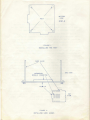
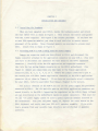
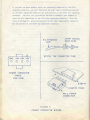
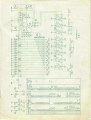
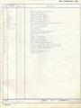
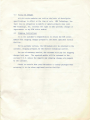
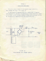
CHAPTER 1
INTRODUCTION
Congratulations on your purchase of a KIM-4 motherboard.
You will now
be able to add additional memory to your KIM system, as well as EROM, ROM, and
other system components as they are introduced by MOS Technology, Inc.
Because the KIM-4 motherboard will form the heart of your microcomputer
system, interconnecting all of your other system components, please take a
few minutes to read this manual completely before attempting to use your KIM-4.
Chapter 2 of this manual describes how to install and check out your KIM-4
motherboard.
Chapter 3 contains schematics and a brief theory of operation,
Chapter 4 contains your warranty information for this module, and Appendix A
describes how to use the direct memory access capability incorporated in
the motherboard.
Appendix B contains a suggested power supply for supplying
current to your KIM system.
There is one important point you should understand before using your KIM-4
motherboard.
Because of the high current involved in supplying power to multiple
expansion boards, MOS Technology, Inc. has designed your KIM system so that you
may use a single unregulated +8v supply for all the cards which you can mount in
your KIM motherboard.
+5v supply.
Do not attempt to power your KIM system through a regulated
Each expansion module provided for the KIM system will contain its
own +5v regulator which will require the +8v as input.
A regulator is provided
on the motherboard to feed regulated +5v to your KIM-1 microcomputer module.
This regulator also works off the +8v which you supply to the motherboard.
If
you do not have a +8v unregulated power supply, refer to Appendix B for a
schematic for such a unit.
Your KIM-4 motherboard has been carefully designed for years of uninterrupted
service to you.
If, for any reason, the unit should fail, follow the instructions
contained in Chapter 4 to provide service for your module.
will be a powerful and useful addition to your KIM system.
We hope that the KIM-4
END V I E W
CHAPTER 2
INSTALLATION AND CHECKOUT
2.1
Installing the Hardware
When you have unpacked your KIM-4, locate the hardware packet and attach
the four rubber feet as shown in Figure 1. Then install the twelve card guides
with the screws supplied.
See Figure 2 for correct placement.
If you have one
or more KIM expansion modules, put them in each card slot to assure correct
placement of the guides.
KIM-1.
2.2
Three threaded spacers are provided to elevate your
Attach them as shown in Figure 3.
Attaching KIM-4 to KIM-1 Using Your Old Power Supply
Remove any expansion cards you have placed in KIM-4 and disconnect the
female connector attached to the application connector on your KIM-1.
(You will
also have to disconnect any connector you have mated to the KIM-1 expansion
connector.)
Carefully slide the KIM application and expansion connector
tabs into the two mating female receptacles on the KIM-4 motherboard.
Figure 4)
(See
Remove any connections you have made to the female application
connector pins, B, C, D, E, F, H, or J.
Remove the jumper connected to pin K.
Now attach your old KIM-1 female application connector to the KIM-4 application
connector tab as shown in Figure 4.
If you have not previously wired a connector
for your KIM-1, refer to your KIM-1 User Manual, Chapter 2, for details.
For initial checkout of the KIM-4 you can use the power supply you previously
connected to KIM-1.
The +5v and +12v pins on the KIM-4 application connector are
routed directly to the KIM-1, bypassing the regulators on the KIM-4; these voltages
are not distributed on the motherboard expansion module connectors.
Thus your old
+5v and +12v power supply cannot be used to power expansion modules inserted in
the motherboard.
Turn your old power supply on, depress the reset button on the
KIM-1 keyboard, and verify that your KIM still operates normally.
If you wish,
load a program from your cassette tape interface and verify that it operates
correctly.
2.3
Attaching Your New Power Supply to KIM-4
Because the motherboard contains a +5v regulator for your KIM-1 and a
+12v regulator for your audio cassette interface, you should power your entire
KIM system from a +8v unregulated power supply and a +15v regulated power supply.
Attach the ground, +8v, and +15v supplies to the KIM-4 power connector as shown
in Figure 5.
Some expansion cards provided with the KIM system also require a
negative voltage.
If you plan on installing such cards you must also connect a
-15v supply to the appropriate pin on the KIM-4 power connector.
expanded, your KIM system may require as much as 15A of +8v.
When fully
To avoid voltage
drops between your power supply and the KIM-4, make sure that you use a heavy
gauge wire for the connection (No. 12 stranded wire is recommended).
Before connecting your new power supply to the KIM-4 power connector,
remove your old +5v and +12v supplies from pins 1, A and N on the application
connector. Disconnect the KIM-1 from your KIM-4 and turn on your new power
supply. Measure the voltage between pin 1 and pin A of the KIM-4 application
connector and insure that it is +5v. Now measure the voltage between pin 1
and pin N of the KIM-4 application connector and insure that it is + 12v. If
all voltages appear correct, turn off your power supply, re-connect the KIM-1
to your KIM-4, and turn your new power supply back on.
You should now verify
that your KIM-1 is operating correctly.
2.4
Installing Expansion Boards Into Your KIM-4
If you have purchased KIM expansion modules, you can now insert them in
the KIM-4 motherboard.
Follow the instructions provided in the manual you
received with each expansion module.
You can verify the operation of each
expansion module by following the checkout instruction included in the owner's
manual for the expansion module.
2.5
The Bus Expansion Connector
On the left-hand end of your KIM-4 there is a bus expansion connector.
This
connector is provided to allow you to add more modules to the KIM bus if you need
to expand beyond the six expansion module connectors provided on the KIM-4.
If you have designed modules which you previously connected to the KIM-1
expansion connector, you will find that the same signals previously present
on the KIM-1 expansion connector are also present on the KIM-4 bus expansion
connector. The wire list provided on the KIM-4 schematic (See Chapter 3)
shows the pin connections to the KIM-4 bus expansion connector. Only the
lines KO through K7, previously present on the KIM-1 application connector,
are not present on the KIM-4 bus expansion connector.
CHAPTER 3
THEORY OF OPERATION
3.1
Introduction
The KIM-4 motherboard is designed to accomplish three functions.
The
first function is that of distributing address, data, and control lines from
the KIM-1 to the expansion module connectors and the bus expansion connector.
Those inter-connections are documented on the interconnection list shown on
the schematic diagram. The second function is to buffer, or provide additional
drive, for the expansion modules from the address and data buses. The third
function is to determine whether the address present on the address bus is
addressing a memory location on the KIM-1 module or the KIM-4 motherboard, and
supply an appropriate signal to the decode line. The motherboard also contains
regulators for the +5v and +12v supplies necessary to operate the KIM-1 and
the audio cassette interface.
3.2
Buffering Circuitry
U6, U8, and U9 form a 16-bit unidirectional bus buffer for the KIM-1
address lines.
These lines will normally be "on" at all times.
The output
3.3
Address Decoding and Lockout Circuitry
Since some addresses below 2000 (hex) are located on the KIM-1 board, the
data bus buffers are used to isolate KIM-1 from the motherboard whenever these
addresses below 2000 are issued.
This function is provided by U5, which is
connected to the three high-order address lines (AB13, 14, 15). If any of
those address lines go high (indicating an address above 2000), then the data
bus buffers will be enabled in the appropriate direction.
The data buffers will
also be enabled if an address between 0400 and 13FF (indicated by the Kl, K2,
K3, and K4 lines) is present.
There are six locations in the memory space which have special
significance in any 6502-based system.
These are locations FFFA through FFFF.
These locations contain the values for the interrupt vectors for the NMI, RST,
and IRQ control lines.
In the KIM-1 system, these interrupt vectors are stored
in locations 17FA - 17FF, the six highest memory locations in KIM-1 since the
three highest address lines are not decoded on KIM-1.
Since the full KIM system,
including the motherboard, does use all sixteen address lines, it is necessary
to detect when one of these six highest addresses is issued by the processor
and force the data to be read from KIM-1 rather than any memory on the motherboard.
This function is provided by U7.
Whenever the thirteen high-order address lines
are all at logic 1, this condition is detected by U7 and the signal generated is
used to disable U5.
When U5 is disabled, the decode line generated as the output
of U5 goes to a logic 1.
This is inverted in U3 and becomes the decode enable
line which is fed back to the KIM-1.
The motherboard addressing is turned off
and the addressing on KIM-1 is turned on, allowing the reset, NMI, and IRQ
vectors to be fetched from the high six memory locations in KIM-1.
Thus, even
with a fully expanded KIM system, these three control vectors will still be under
the control of the KIM monitor.
CHAPTER 4
WARRANTY AND SERVICE
Should you experience difficulty with your KIM-4 module and be
unable to diagnose or correct the problem, you may return the unit to
MOS Technology, Inc. for repair.
4.1
In-Warranty Service
All KIM series Microcomputer Modules are warranted by MOS Technology, Inc.
against defects in workmanship and materials for a period of ninety (90) days
from date of delivery. During the warranty period, MOS Technology, Inc. will
repair or, at its option, replace at no charge components that prove to be
defective provided that the module is returned, shipping prepaid, to:
KIM Customer Service Department
MOS Technology, Inc.
950 Rittenhouse Road
Norristown, Pennsylvania
19401
This warranty does not apply if the module has been damaged by accident
or misuse, or as a result of repairs or modifications made by other than
authorized personnel at the above captioned service facility.
No other warranty is expressed or implied. MOS Technology, Inc. is not
liable for consequential damages.
4.2
Out-Of-Warranty Service
Beyond the ninety (90) day warranty period, KIM modules will be
repaired for a reasonable service fee. All service work performed by
MOS Technology, Inc. beyond the warranty period is warranted for an
additional ninety (90) day period after shipment of the repaired module.
4.3
Policy On Changes
All KIM series modules are sold on the basis of descriptive
specifications in effect at the time of sale. MOS Technology, Inc.
shall have no obligation to modify or update products once sold.
MOS Technology, Inc. reserves the right to make periodic changes or
improvements to any KIM series module.
4.4
Shipping Instructions
It is the customer's responsibility to return the KIM series
module with shipping charges prepaid to the above captioned service
facility.
For in-warranty service, the KIM module will be returned to the
customer, shipping prepaid, by the fastest economical carrier.
For out-of-warranty service, the customer will pay for shipping
charges both ways. The repaired module will be returned to the
customer C.O.D. unless the repairs and shipping charges are prepaid
by the customer.
Please be certain that your KIM module is safely packaged when
returning it to the above captioned service facility.
APPENDIX A
USING DMA WITH THE KIM-4
Some advanced applications involving access to high-speed peripherals
such as floppy discs require the ability to stop the processor and allow
another device (usually called a 'controller') to gain control of the
address and data lines in order to transfer a quantity of data in or out
of the memory. This is called DMA or direct memory access.
APPENDIX B
A KIM SYSTEM POWER SUPPLY
The circuit shown in Figure B-l will provide enough current for a
fully expanded KIM system - +8v at about ISA.
Be sure to wire all components with #10 or heavier wire.
A suggested
transformer for T h i s the model 16-8 manufactured by Signal Transformer Company.
Be sure to wire the two secondary windings in PHASE across the bridge rectifier.
The .O1 ohm resistor is composed of a six inch length of #22 wire.