1
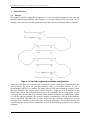
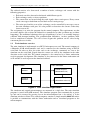
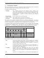
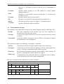
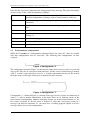
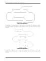
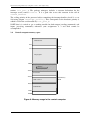
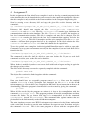
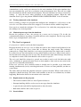
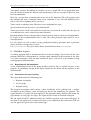
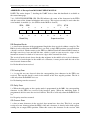
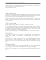
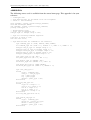
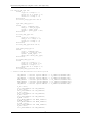
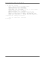
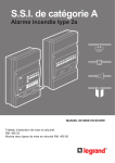
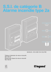
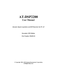
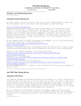
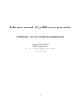
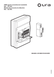
2010-01-29, Department of computer science and engineering
EDA222 Real time systems
Laboratory assignments:
CONTROL AND MONITORING A MODEL RAILROAD
Contents:
1
1.1
1.2
1.3
1.4
1.5
2
2.1
2.2
2.3
2.4
3
3.1
4
4.1
4.2
5
5.1
5.2
6
6.1
6.2
INTRODUCTION ................................................................................................. 2
Purpose
Train simulator overview
Train simulator commands
Train simulator messages
Train simulator configurations
2
2
3
4
5
COMMUNICATING WITH THE SIMULATOR ..................................................... 7
Control and status registers
Sending commands to the simulator
Receiving messages from the simulator.
Control computer memory space
7
7
7
8
ASSIGNMENT 1 .................................................................................................. 9
Resource handler
9
ASSIGNMENT 2 ................................................................................................ 10
Testing commands to the simulator
Monitoring messages from the simulator
11
11
THE FINAL ASSIGNMENT................................................................................ 11
Requirements on the program
Practical hints
11
11
CRITERIAS TO PASS ....................................................................................... 12
Reporting and documentation
Instructions for report writing
12
12
1
2010-01-29, Department of computer science and engineering
1 Introduction
1.1
Purpose
The purpose with this laboratory assignment is to give a practical example of real time and
machine oriented programming. Our example is a model railroad where two trains can be
moving at the same time and independent of each other. The model railroad looks as follows:
Figure 1: Final lab assignment simulator configuration
Along the track there are exchanges and a number of sensors which gives information on the
train positions. To avoid the practical problems with a real model railroad, we use a
microcomputer (HCS12) to simulate the model railroad. This microcomputer system is called
the train simulator. The picture of the model railroad is displayed in an X-window on the
Linux work station. The communication between the simulator and the workstation is via a
serial port. The model railroad is controlled from another microprocessor (MC68340) which
we call the control computer. The control computer communicates with the train simulator
using a serial link. This link is used to read sensor messages from the simulator and to send
messages to the simulator to drive the trains and set the exchanges. A serial link between the
control computer and the Linux workstaton is used to download the program to the control
computer.
2
2006-10-09, Department of computer science and engineering
The railroad consists of a short track, a number of trains, exchanges and sensors with the
following properties:
•
•
•
Each train can drive forward or backward with different speeds.
Each exchange can be set in two positions.
The sensors that are located along the track signals when a train passes. Every sensor
sends a message at both front end and back end of a train passage.
• The train speed and the state of the exchanges can be controlled by messages sent to
the train simulator serial port. It is also possible to deactivate the sensors so that they
do not react at all.
The assignment is to write the program for the control computer. The requirements are that
two trains shall be able to share the railroad in a controlled way (that is without any accidants
happening). The traditional solution to this type of problems is to use C or assembly language
combind with interrupt handling. The synchronisation difficulties in these problems often
lead to complicated solutions. We will se how elegant this problem can be solved using
concurrent processes in Ada.
1.2
Train simulator overview
The train simulator is implemented on a HCS12 microprocessor card. The control computer is
a Motorola 68340 microcontroller card and is connected to the simulator using an RS232
serial link. In order to drive the trains and set the exchanges, commands are sent to the
simulator on the serial link. Signals from the sensors are sent by the simulator in the other
direction on the serial link. The control computer is also connected to a Linux workstation
used for program development. The simulator is also connected to the Linux workstation and
an X-window is used to present the simulated railroad.
Work station
Train simulator
Terminal
window 1
Control computer
(MC68340 based)
Simulator computer
Terminal
window 2
(MC68HCS12 based)
Figure 2: Train simulator organisation
The simulator and control microcomputers are mounted in a single box. The train simulator
program is stored in FLASH memory. The simulator program starts automatically at power
up, and can be restarted by pressing reset at the microcomputer box or by writing ‘q’ in the
simulator window at Linux. The control computer contains a simple monitor db68 that makes
it possible to communicate with the Linux workstation and to download programs to the
microcomputer.
2
2006-10-09, Department of computer science and engineering
1.3
Train simulator commands
This and the following section give a description of the commands that can be sent between
the control computer and the simulator and the errors that can occur.
Commands can be of four types:
Configure
This command restarts the train simulator. Trains, exchanges and
sensors will “momentarily” be set to their initial positions (one of the
few occasions there the model surpasses reality in performance). The
command makes it possible to choose between a few different
configurations.
Set exchange
Set an exchange in the specified position.
Activate sensor
The specified sensor is activated or deactivated.
Set speed
The speed for the specified train is set to specified value.
The syntax of the configure command allows for 8 different configurations, each with a
maximum of 16 exchanges, 16 sensors and 8 trains with a maximum of four speeds. Currently
only four configurations are implemented. These configurations are described below.
A command is always a group of eight bits transported over the serial link. This will be further
explained below. Commands have a type field (the two least significant bits) used for a
command type code. The other six bits have different meaning dependent of the type code.
Command codes
MSB
7
Bit number
6
5
4
LSB
3
Value field
0
Log
0
Off
0
Active
Rev
Rec.
Speed
2
1
Command type
0
Type field
C-number
0
0
Configure
E-number
0
1
Set exchange
S-number
1
0
Activate sensor
1
1
Set speed
T-number
The simulator interprets bits or bit fields in a command as follows:
Log
A flag that specifies that activities shall be logged in the simulator
window Simplifies debugging of the program. Set this bit to ‘1’ if you
want the simulator to print out the received commands, set this bit to
‘0’ if you want to suppress this action.
Rec
A flag that specifies that receipts shall be sent or not. Set this bit to ‘1’
if you want the simulator to acknowledge a command, set this bit to ‘0’
if you don’t want any acknowledges.
C-number
Specifies which track configuration you desire. The field should
contain a binary number (0-7). NOTE: Some of these numbers are not
valid since they not correspond to an implemented configuration (see
below).
Off
Specifies if an exchange shall be set for turnoff or thoroughfare. Set
3
2006-10-09, Department of computer science and engineering
this bit to ‘1’ if turnoff is desired, set this bit to ‘0’ if thoroughfare is
desired.
E-number
Specifies which exchange to set. This should be a binary number
ranging from 0 to 15.
Active
Specifies if a sensor shall be activated (set this bit to ‘1’) or deactivated
(set this bit to ‘0’).
S-number
Specifies which sensor to activate (0-15).
Rev
Specifies if a train shall be driven forward (0) or backward (1).
Speed
the wanted speed for a train, 0 = stopped, 3 = maximum speed.
T-number
Specifies which train shall be controlled.
1.4
Train simulator messages
The simulator sends notification messages to the control computer upon the following events:
Receipt
The latest command of the specified type has been completed or
alternatively rejected for some reason
Passage
A sensor reacts when a train arrives to or leaves the place where the sensor
is located.
Catastrophe
A train has collided, deranged or reversed. When a catastrophe is reported
the simulator has to be reconfigured.
The simulator recognizes the following “catastrophic” conditions:
Collision
A train may not be driven against another train or into a stop block.
Deranging
A train may not be driven into an exchange set in the wrong position nor
can an exchange be repositioned while a train is passing.
Reversing
The direction of movement cannot be changed while a train is moving. To
prevent a catastrophe the train first have to be stopped.
Addressing
A command has been given that references a component (train, exchange,
sensor) that do not exist in the current configuration
Messages returned from the simulator are encoded as follows:
Coding of simulator messages
MSB
7
Bit number
6
5
4
LSB
3
2
1
Value field
0
0
0
Start
Rev
Derang
0
0
Type field
Error
Type
S-number
Coll
Message type
T-number
4
0
0
Receipt
0
1
Sensor signal
1
0
Catastrophe
2006-10-09, Department of computer science and engineering
Note that the type field is importanta for interpretation of the message. The general meanings
of codes in the “value” field are explained as follows:
Error
Specifies that a command have been completed (0) or rejected (1) as the
specified configuration, exchange, train or sensor cannot be addressed.
Type
Specifies the type for the message being acknowledged (see coding of
commands).
Start
Specifies that a sensor has reacted at the beginning (1) or end (0) of a
train.
S-number
specifies which sensor has reacted.
Rev
Specifies that direction of movement was reversed while the train was
moving (1).
Derang
Specifies deranging (1).
Coll
Specifies collision (1).
T-number
Specifies which train has been hit by catastrophe.
1.5
Train simulator configurations
While the C-number in a configuration command allows any value, 0-7, there are actually
only four configurations that are valid (0-3). The following four configurations are thus
accepted:
Figure 3: Configuration ‘0’
The configuration shown in Figure 3 is intended for simple basic exercises such as to start and
stop a train. The rails are represented with strait lines, and the end of a railroad track is marked
with ’I’. A train is represented by a series of ‘o’ with the train number interjected. The train in
the figure moves to the right, when given a command to move forward.
Figure 4: Configuration ‘1’
Configuration ‘1’, shown in Figure 4, is intended for test of sensors. Sensors are marked by an
arrow (’^’) with its number immediately to the right. There are 16 different sensors in the
most advanced configuration. Numbers indicating sensors are in hexadecimal format, i.e. the
first sensor is denoted ‘0’, the last sensor is denoted ‘F’. Note that a sensor pass results in a
message sent from the simulator. I.e. you must have a working program capable to receive
messages before you test this configuration.
5
2006-10-09, Department of computer science and engineering
Figure 5: Configuration ‘2’
Configuration ‘2’, shown in Figure 5, can be used to test exchanges. All exchanges are shown
in the turnoff position. The number of the exchange is shown above the movable part of the
exchange.
Figure 6: Configuration ‘3’
Configuration ‘3’, Figure 6 shall be useed in the final assignment. All exchanges are shown in
turnoff position. The intention is to get the two trains moving simultaneously without
colliding.
6
2006-10-09, Department of computer science and engineering
2 Communicating with the simulator
A serial link is used for the communication with the simulator. The Motorola 68340 processor
has two serial ports. Port A is used for communication with the Linux workstation and port B
is used for communication with the train simulator.
2.1
Control and status registers
The serial module in the 68340 processor have close to ten control registers that have to be
programmed with the correct bit pattern to get the circuit working in the intended way.
A proper initializition of those registers are programmed by calling the routine Init_port_B in
the given package traintypes. You don’t have to be further bothered by this but you do have to
recognize that the registers that have to be explicitly handled by your program is a status
register and a data register for sending and reading characters on port B.
These registers have the following addresses:
Short
name
Description
Address
SRB
Status register port B
FFFFF719
TBB
Data register for sending to port B
FFFFF71B
RBB
Data register for receiving from port B
FFFFF71B
All these registers have 8 bits. All bits in the data register are used why both sent and received
characters consist of 8 bits. The bits in the status register are described in the attached manual
pages (se “Appendix: Excerpt from MC68340 USER’S MANUAL”). Observe that the bits are
numbered according to the Little Endian method (from right to left) in the manual. The Gnu
Ada 95 compiler on the other hand uses the Big Endian method (from left to right) in a record
representation clause.
A number of control registers are already defined in the package traintypes, but these are only
used by the routine init_port_B. The registers mentioned above remains to be defined as
part of your assignment.
2.2
Sending commands to the simulator
Sending commands to the simulator is done by writing a character in the data register for port
B (TBB). Beware that this is a direct communication with the underlying hardware. Before
writing to the data register a check must be made that the circuit is prepared to receive a new
character. This is done by reading the status register (SRB) and check that the correct bit is
active.
2.3
Receiving messages from the simulator.
The reception of characters from the train simulator is interrupt driven. Interrupt routines in
Ada 95 is programmed using protected objects. To connect an interrupt handler with its
interrupt vector, the routine attach_handler in the package Ada.interrupts is used.
Alternatively the Pragma attach_handler can be used. The interrupt vector to be used is
defined in the package Ada.interrupts.Names and is called PORTBINT. Finally the
serial module in the processor must be ordered to use this interrupt vector. This is done by the
7
2006-10-09, Department of computer science and engineering
routine init_port_B. The package traintypes includes a constant declaration for the
interrupt vector, named ivector. It is a good idea to use this constant in the call of
attach_handler.
The ceiling priority of the protected object containing the interrupt handler should be set to
104 using pragma interrupt_priority. This corresponds to the hardware priority 4,
which is set for the serial module by init_port_B.
NOTE that it is cruisal to get a working module for both output (sending commands) and
inputs (receiving commands) otherwise your assignments 2, 3 and final cannot be
accomplished.
2.4
Control computer memory space
0
db68 data area
2000
SRAM
3000
512 K
Ada program
7FFFF
no memory
100000
Boot loader
11 0000
Flash memory
db68 code area
512 K
120000
Flash libraries
170000
17FFFF
Figure 6: Memory usage in the control computer
8
2006-10-09, Department of computer science and engineering
3 Assignment 1
3.1
Resource handler
The first assignment is to write a resource handler for allocation of the single tracks. This
assignment does not use the microcomputer system and is developed on a native Ada 95
compiler on either Linux or a Windows PC. However the resource handler shall be written so
that it can be included in the final train program without changes. For this reason the program
is structured as an Ada package and a simple main program for testing purposes. Skeleton
files for the assignment are given in the directory:
/chalmers/groups/cab_ce_edu_2010_eda222_rt_-/lib/lab1
at the Linux lab accounts. They are also available at the course homepage as:
Assignment1.zip.
The directory (this zip-file) contains the following files
resource.ads
resource.adb
traintypes.ads
restest.adb
Start by creating a directory lab1 using the command: mkdir lab1. Copy the given files to
this directory with the command:
cp /chalmers/groups/cab_ce_edu_2010_eda222_rt_-/lib/lab1/* lab1
The file resource.ads is the complete package specification for the recourse handler. It is
demanded that this specification remains unchanged. The file resource.adb is a skeleton
body for the resource handler. The major part of the assignment is to complete this file. The
file restest.adb is the main program used to test that the resource handler is working
correctly. This program is only a skeleton that has to be completed. The file
traintypes.ads only contains the type definition for a track. This file should not be
changed.
The program can be compiled with the command: gnatmake restest.adb and then
executed by the command: ./restest
The test program should test both correct and incorrect usage of the resource handler. It is
however allowed to make temporary changes to test certain errors, for example that the same
track cannot be allocated another time while it is still in use.
In the final solution this resourse handler shall be used to control access to the three singletracks in figure 1. It is recommend that the tracks is given the numbers 0..6. This means that
the single-tracks will get numbers 1, 3 and 5. This is the reason why the type track_part_type
has interval 1..5 although there is only three resourses to control.
There is no reporting needed for this assignment. Continue with assignment 2 when you have
a working resource handler.
9
2006-10-09, Department of computer science and engineering
4 Assignment 2
In this assignment the Gnu Ada95 cross compiler is used to develop a control program for the
train simulator that can be downloaded to and executed at the control microcomputer. Observe
that this compiler is only available at the Linux machines in the Computer Engineering lab.
Start by creating a new directory lab2 and copy the given files to this directory with the
command :
cp /chalmers/groups/cab_ce_edu_2010_eda222_rt_-/lib/lab2/* lab2
Directory lab2 should now contain the files traintypes.ads, command.ads,
command.adb and main.adb. The file traintypes.ads contains type definitions for
communication with the train simulator. The file command.ads specifies the interface to
low level communication routines. This file is complete and may not be changed. The file
command.adb contains the body for the low level communication routines and also the
routine init_port_B. This file is incomplete and has to be completed. The file main.adb
contains a skeleton main program that has to be completed. In the final solution the files
resource.ads and resource.adb from lab1 should also be copied here.
To use the gada68 cross compilers /cab/ce/sw/gada68/Linux/bin must be added to your path.
Commands to set up your environment correctly for the compilers if you use bash shell can be
found in the file:
/chalmers/groups/cab_ce_edu_2010_eda222_rt_-/lib/bashrc
The commands in this file shall be added to your own .bashrc file. If you use tcsh shell
commands to add to your .tcshrc file can be found in:
/chalmers/groups/cab_ce_edu_2010_eda222_rt_-/lib/tcshrc
When .bashrc is modified you have start a new shell with bash or logout and log in again for
the changes to have effect.
The files in lab2 directory can now be separately compiled with the command:
gada68 name.adb
The object files can then be linked together with the command:
gbind68 main
Now you should have an executable program named main.x. Now start the terminal
emulator 68term in a local X-window and download the file main.x to the 68340
microcomputer (se “Gnu Ada95 Cross Compiler for MC6xx0” for an instruction on how to do
downloading). When the program is downloaded it can be started by giving the command:
go 3000
When all files needed by the program are written it is best to do recompilations with the
command gnatmake68 main. This program performs all needed recompilations and then
executes the linker. To get shorter load time it is recommended to use the command
gnatmake68f instead of gnatmake68. This command links against routines that are
preinstalled in the flash memory on the 68340 microcomputer.
The train simulator executes on a HCS12 microprocessor connected to the Linux workstation
with a serial link. In order to start the train simulator, first open an extra X-window and give
the command 68termb. This is the same program as 68term with the exception that it
10
2006-10-09, Department of computer science and engineering
communicates on the serial port connected to the train simulator. If the train simulator does
not start automatically, press the reset button at the microcomputer box. This will reset both
the train simulator and the control microcomputer. The train simulator can also be restarted by
writing ‘q’ (only the letter) when positioned in the simulator window. When the train
simulator starts it gives the printout “READY FOR CONFIGURATION” in the X-window.
4.1
Testing commands to the simulator
Start by writing a simple test program that configures the simulator as configuration 0 and
starts the train. The train need not to be stopped, it is ok that it collides with the stop block.
Next step is to control the exchanges. Use configuration 2 to verify that your program can set
the exhanges in a desired position.
4.2
Monitoring messages from the simulator
Rewrite the program so that the passage of a sensor can be detected. To do this the
communication routines in package command.adb have to be completed. For this step (and the
future steps) configuration 3 can be used.
5 The final assignment
Configuration 3 shall be used in the final assignment.
Program the body of task type train to allow the train to drive forward and backward at the
track. Use the package resource from lab1 to allocate the single tracks. The exchanges
connected to a single track should be set in correct position before the single track is entered.
It is allowed to use the train number to select which double track to use. Other criteria such as
the direction of the train may also be used. The direction of the train should change only when
an endpoint is reached. The train should be able to drive at speed 3.
The train task should be written in a general way so that it can be used for both trains with
only a minimum of parameterization based on train number. Only activate one train in this
step, but test with both train numbers.
If the train task have been carefully written it should now be possible to get both trains
running simultaneously just by activating both trains. If there are some problems you have to
correct them.
The trains shall start from the endpoints and move against each other. When a train reaches an
endpoint it should turn back. The trains shall continue to run for ever without any accidents
happening. Both trains shall be in movement at the same time.
5.1
Requirements on the program
• The resource handler shall use Ada 95 protected objects.
• Interrupt handling shall be used to receive messages from the simulator.
• A general train task shall be implemented to drive the trains.
• Both trains shall be able to run at speed 3.
5.2
Practical hints
11
2006-10-09, Department of computer science and engineering
You should structure the problem by drawing an access graph. The access graph shall show
the call structure between the different tasks and packages. An access grapf is required in your
final documentation
Wait for a receipt when a command has been sent to the simulator. This will guarantee that
the simulator has read a command before a new command is sent. You will probably not be
able to solve this assignment unless you do so.
Tasks start in an arbitrary order. They have to be synchronized at start.
Speed 0 forward is not the same as speed 0 backward.
Trains have inertia. At the end stations the trains have to wait for 10 seconds after the speed is
set to 0 before they can be started in the other direction.
Recommendation: Do not call procedures in other protected objects from an interrupt handler.
If despite of this recommendation this is done, the called protected object must be set to
interrupt priority.
It is not allowed to call an entry (or any potentially blocking operation) from a protected
object when the real time annex is used.
Use gnatmake68f. This gives much shorter download times than gnatmake68.
6 Criterias to pass
A working program shall be demonstrated for an instructor during a lab session and the same
program shall also be documented in a written report submitted to the instructor in due time
(see course homepage). Only the final solution of source code needs to be submitted along
with appropriate documentation.
6.1
Reporting and documentation
At the demonstration each of the group members shall be able to explain all parts of the
program. A preliminary version of the report should also be shown for the instructor at the
demonstration.
6.2
Instructions for report writing
The report shall include the following parts:
•
Program description
•
Access graph
•
Program listing
The program description shall contain a short description of the problem and a detailed
description of the packages, tasks and protected objects that implements the program. The
report should be 3-4 pages and well structured. The program listings shall have file name and
page number at every page (use a2ps). The report may be written in Swedish or English.
The lab report should be submitted before the deadline specified at the course homepage. If
the report is not approved it is returned and have to be resubmitted after corrections. The last
date for approval is given at the course home page.
12
2006-10-09, Department of computer science and engineering
13
2006-10-09, Department of computer science and engineering
APPENDIX A: Excerpt from MC68340 USER’S MANUAL
NOTE: The entire chapter 7, detailing the UART device, from this handbook is available at
the course homepage.
7.4.1.5 STATUS REGISTER (SR). The SR indicates the status of the characters in the FIFO
and the status of the channel transmitter and receiver. This register can only be read when the
serial module is enabled (i.e., the STP bit in the MCR is cleared).
SRA,
SRB
$711,
$719
7
6
5
4
3
2
1
0
RB
FE
PE
OE
TxEMP
TxRDY
FFULL
RxRDY
0
0
0
0
0
0
0
RESET:
0
Read Only
Supervisor/User
RB-Received Break
1 = An all-zero character of the programmed length has been received without a stop bit. The
RB bit is only valid when the RxRDY bit is set. Only a single FIFO position is occupied when
a break is received. Further entries to the FIFO are inhibited until the channel RxDx returns to
the high state for at least one-half bit time, which is equal to two successive edges of the
internal or external 1x clock or 16 successive edges of the external 16x clock.
The received break circuit detects breaks that originate in the middle of a received character.
However, if a break begins in the middle of a character, it must persist until the end of the
next detected character time.
0 = No break has been received.
FE-Framing Error
1 = A stop bit was not detected when the corresponding data character in the FIFO was
received. The stop-bit check is made in the middle of the first stop-bit position. The bit is
valid only when the RxRDY bit is set.
0 = No framing error has occurred.
PE-Parity Error
1 = When the with parity or force parity mode is programmed in the MR1, the corresponding
character in the FIFO was received with incorrect parity. When the multidrop mode is
programmed, this bit stores the received A/D bit. This bit is valid only when the RxRDY bit is
set.
0 = No parity error has occurred.
OE-Overrun Error
1 = One or more characters in the received data stream have been lost. This bit is set upon
receipt of a new character when the FIFO is full and a character is already in the shift register
waiting for an empty FIFO position. When this occurs, the character in the receiver shift
14
2006-10-09, Department of computer science and engineering
register and its break detect, framing error status, and parity error, if any, are lost. This bit is
cleared by the reset error status command in the CR.
0 = No overrun has occurred.
TxEMP-Transmitter Empty
1 = The channel transmitter has underrun (both the transmitter holding register and transmitter
shift registers are empty). This bit is set after transmission of the last stop bit of a character if
there are no characters in the transmitter holding register awaiting transmission.
0 = The transmitter buffer is not empty. The transmitter holding register is loaded by the
CPU32, or the transmitter is disabled. The transmitter is enabled/disabled by programming the
TCx bits in the CR.
TxRDY-Transmitter Ready
This bit is duplicated in the ISR; bit 0 for channel A and bit 4 for channel B.
1 = The transmitter holding register is empty and ready to be loaded with a character. This bit
is set when the character is transferred to the transmitter shift register. This bit is also set when
the transmitter is first enabled. Characters loaded into the transmitter holding register while
the transmitter is disabled are not transmitted and are lost.
0 = The transmitter holding register was loaded by the CPU32, or the transmitter is disabled.
FFULL-FIFO Full
1 = A character was transferred from the receiver shift register to the receiver FIFO and the
transfer caused the FIFO to become full (all three FIFO holding register positions are
occupied).
0 = The CPU32 has read the receiver buffer and one or more FIFO positions are available.
Note that if there is a character in the receiver shift register because the FIFO is full, this
character will be moved into the FIFO when a position is available, and the FIFO will remain
full.
RxRD-Receiver Ready
1 = A character has been received and is waiting in the FIFO to be read by the CPU32. This
bit is set when a character is transferred from the receiver shift register to the FIFO.
0 = The CPU32 has read the receiver buffer, and no characters remain in the FIFO after this
read.
15
2006-10-09, Department of computer science and engineering
APPENDIX B:
The following source code is available from the course home page. This appendix is for your
reference.
-- traintypes.ads
-- Type declarations for the Ada95 train lab assignment
-- 06-09-27 Arne Dahlberg
with calendar, system, system.storage_elements;
with Ada.Interrupts.Names;
use calendar, system, system.storage_elements;
package traintypes is
-- Miscellaneous types
-- 8-bit type for genaral use
subtype byte is integer range 0..255;
-- Type for accessing hardware registers
type bits is range 0..255;
for bits’size use 8;
-- Type declarations for commands to the simulator
type command_type is (CONF, SWITCH, SENS, SPEED);
for command_type use (CONF => 0, SWITCH => 1, SENS => 2, SPEED => 3);
subtype
subtype
subtype
subtype
subtype
conf_nr_type is integer range 0..7;
train_nr_type is integer range 0..7;
switch_nr_type is integer range 0..15;
sens_nr_type is integer range 0..15;
speed_type is integer range 0..3;
type yesno_type is (NO, YES);
for yesno_type use (NO => 0, YES => 1);
type direct_type is (STRAIT, OFF);
for direct_type use (STRAIT => 0, OFF=> 1);
type drive_dir_type is (FORW, BACKW);
for drive_dir_type use (FORW => 0, BACKW => 1);
type conf_cmd_type is
record
ctype : command_type;
conf_nr : conf_nr_type;
ack : yesno_type;
log : yesno_type;
unused : yesno_type := NO;
end record;
for conf_cmd_type use
record
ctype at 0 range 6..7;
conf_nr at 0 range 3..5;
ack at 0 range 2..2;
log at 0 range 1..1;
unused at 0 range 0..0;
end record;
for conf_cmd_type’size use 8;
type switch_cmd_type is
record
ctype : command_type;
switch_nr : switch_nr_type;
direct : direct_type;
unused : yesno_type := NO;
end record;
16
2006-10-09, Department of computer science and engineering
for switch_cmd_type use
record
ctype at 0 range 6..7;
switch_nr at 0 range 2..5;
direct at 0 range 1..1;
unused at 0 range 0..0;
end record;
for switch_cmd_type’size use 8;
type sens_cmd_type is
record
ctype : command_type;
sens_nr : sens_nr_type;
active : yesno_type;
unused : yesno_type := NO;
end record;
for sens_cmd_type use
record
ctype at 0 range 6..7;
sens_nr at 0 range 2..5;
active at 0 range 1..1;
unused at 0 range 0..0;
end record;
for sens_cmd_type’size use 8;
type speed_cmd_type is
record
ctype : command_type;
train_nr : train_nr_type;
speed : speed_type;
drive_dir: drive_dir_type;
end record;
for speed_cmd_type use
record
ctype at 0 range 6..7;
train_nr at 0 range 3..5;
speed at 0 range 1..2;
drive_dir at 0 range 0..0;
end record;
for speed_cmd_type’size use 8;
-- Control word declarations for serial port B
ILR_address : constant System.address := to_address(16#FFFFF704#);
IVR_address : constant System.address := to_address(16#FFFFF705#);
ISR_address : constant System.address := to_address(16#FFFFF715#);
IER_address : constant System.address := to_address(16#FFFFF715#);
MR1B_address : constant System.address := to_address(16#FFFFF718#);
MR2B_address : constant System.address := to_address(16#FFFFF721#);
CSRB_address : constant System.address := to_address(16#FFFFF719#);
CRB_address : constant System.address := to_address(16#FFFFF71A#);
D_ILR : bits;
for D_ILR’address use ILR_address;
D_IVR : bits;
for D_IVR’address use IVR_address;
D_ISR : bits;
for D_ISR’address use ISR_address;
D_IER : bits;
for D_IER’address use IER_address;
D_MR1B : bits;
for D_MR1B’address use MR1B_address;
D_MR2B : bits;
for D_MR2B’address use MR2B_address;
D_CSRB : bits;
for D_CSRB’address use CSRB_address;
D_CRB : bits;
for D_CRB’address use CRB_address;
17
2006-10-09, Department of computer science and engineering
--
Init definitions for Port B
ivector : constant := Ada.Interrupts.Names.PORTBINT;
cmd_reset_receiver : bits := bits(16#20#);
cmd_reset_transmitter : bits := bits(16#30#);
cmd_reset_errorstatus : bits := bits(16#40#);
cmd_reset_break : bits := bits(16#50#);
rec_irq_enable: bits := bits(16#24#); -- rec int. B + brk int. A enable
cmd_enable_receiver : bits := bits(16#01#);
cmd_enable_transmitter : bits := bits(16#04#);
MR1B_init : constant bits := bits(16#13#); -- 8 bits, no parity
MR2B_init : constant bits := bits(16#07#); -- normal, 1 stop bit
CSRB_init : constant bits := bits(16#BB#); -- 9600 baude, Rx and Tx
ILEVEL : bits := bits(16#04#); -- Interrupt level port A and portB !!
VECTOR : bits := bits(ivector); -- Interrupt vector port A and port B !!
-- Type declarations for messages from simulator
--Write your own declarations for this part
end traintypes;
18