1
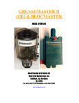
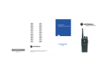
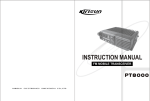
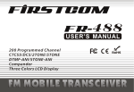
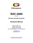
1 of 12 2011-9-23
INSTRUCTION MANUAL
PT8100
VHF/UHF MOBILE RADIO
INSTRUCTION MANUAL
VHF/UHF MOBILE RADIO
MANDATORY SAFETY INSTRUCTIONS TO INSTALLERS AND USERS
Use Only manufacturer or dealer supplied antennas.
Antenna minimum safe distance: 108 cm.
Antennas used for this transmitter must not exceed an antenna gain of 3 dB.
The FCC (Federal Communications Commission) has adopted a safety standard for human exposure to RF
energy which is below the OSHA (Occupational Safety and Health Act) limits.
Antenna mounting: The antenna supplied by the manufacturer or radio dealer must not be mounted at a location
such that during radio transmission, any person can come closer than the above indicated minimum safe distance
to the antenna (i.e. 108cm).
To comply with current FCC RF Exposure limitations, the antenna must be installed at or exceeding the minimum
safe distance indicated above, and in accordance with the requirements to the antenna manufacturer or supplier.
Vehicle installation: The antenna can be mounted at the center of a vehicle metal roof or trunk lid if the minimum
safe distance is observed.
Antenna substitution: Don't substitute any antenna for the one supplied or recommended by the manufacturer
or radio dealer. You may be exposing person(s) to excessive radio frequency radiation. You may contact your radio
dealer or the manufacturer for further instructions.
Maintain a separation distance from the antenna to person(s) at least 108cm.
This transmitter is authorized to operate with a maximum duty factor of 50%, in a typical push-to-talk
mode, for satisfying FCC RF exposure compliance requirements.
Warning
Caution:
Changes or modifications not expressly approved
by the party responsible for compliance could void
the user's authority to operate the equipment.
Operating Instruction of PT8200
Contents
1. Package-opened Inspection and Installing................................................................................... 2
2. Radio Overview ............................................................................................................................ 3
3. Basic Operation............................................................................................................................ 5
4. Programmable Button Function.................................................................................................... 5
5. Radio Call..................................................................................................................................... 6
6. Select Zone .................................................................................................................................. 7
7. Talkaround.................................................................................................................................... 7
8. Utilities.......................................................................................................................................... 7
9. Scan ............................................................................................................................................. 8
2 of 12 2011-9-23
9.1 Start/End Scan Function .................................................................................................. 8
9.2 Nuisance Delete.................................................................................................................. 8
9.3 Edit Scan List ...................................................................................................................... 8
9.4 Add or Delete the Channels in the Scan List............................................................................... 8
9.5 Set Priority Channel ........................................................................................................................ 8
10. FCS scan .................................................................................................................................................. 9
10.1 Enable FCS Scan function........................................................................................................... 9
10.2 Edit FCS scan list .......................................................................................................................... 9
11. OST.......................................................................................................................................................... 10
12. Channel edit (Manual modulation) ...................................................................................................... 10
13. Wired Clone Mode ................................................................................................................... 11
14. Trouble Shooting Guide............................................................................................................ 11
15. Major Specifications ................................................................................................................. 12
1. Package-opened Inspection and Installing
Please check the host in the package and the supplied accessories in the following table before
using. Any articles are found lost or damaged, please contact the distributor without delay.
1.1 Supplied Accessories
No.
Accessories
Quantity
01
Fixed bracket
1
02
Power Cable
1
03
Hand Microphone
1
04
Microphone Hanger
1
05
M4*10 Combination Screw
4
06
M4*16 Self-tapping Screw
2
07
M5*16 Self-tapping Screw
4
08
Instruction Manual
1
09
Warranty Card
1
Fixed bracket
Power Cable
Hand Microphone
Microphone Hanger
M4*10 Combination Screw
M5*16 / M4*16 Self-tapping
Screw
1.2 Preparation
1.21 Connection of Power Cable
3 of 12 2011-9-23
First of all, please check whether there is a hole for the power cable on the insulating board. If no,
please bore the board with the suitable drill bit and fix a rubber grommet on it.
Afterwards, please have the cable pass through the insulating board and lead from the car into the
car engine. Connect the red conductor to the positive terminal of the accumulator and the black
conductor to the negative terminal.
At last, ring the remained conductor and fix it.
Note: Please maintain the sufficient relaxation of the power cable to make it convenient to dismantle
the radio in the state of power connection.
1.22 Radio Installing
Warning: For passengers’ safety, please fix the radio firmly on the fixed bracket so that the radio will
not be loosened in case of collision.
1) The fixed bracket is taken as an example. Draw the position and drill a hole on the instrument
panel first, and then install the fixed bracket with 4 M5*16 self-tapping screws. (Note: please fix
the radio at the position convenient for operation and control, and leave an enough space for
fixation and connection of the cable.)
2) Slide the radio into the fixed bracket and fix it with 4 M4*10 combination screws (plus plain
washer and spring washer). (Different combinations of fixing holes are selectable to adjust the
radio to the proper height and visual angle.)
3) Connect the antenna and the power cable to the radio.
4) Install the microphone hanger at the position easy to use, with 2 M4*16 self-tapping screws.
(The microphone and its cable should be fixed at the position not affecting safe driving.)
5) Connect the microphone to the microphone jack on the front panel of the radio and put it on the
hanger.
Note: When replacing the protective tube for the power cable, please use the one of the same
specification without fail. It is not allowed to change it into the tube of higher capacity.
2.Radio Overview
2.1 Description of External View
4
2
3
⑾
5
(1)
6
7
8
9
1
power button
Press this button for a long time (more than 1.5 seconds) to switch the radio on/off.
(2)LED indicator
The red indicator will light while transmitting; the green indicator will light when it receives the
carrier.
The led flashes orange on received correct DTMF/2Tone signaling.
The red indicator flashes in the scanning process.
4 of 12 2011-9-23
(3)LCD display screen
For details, see “LCD Display”.
(4)Volume Control knob
To be used to adjust volume.
(5)Microphone/Programming Interface
(6)
button (programmable button)
(7)
button (programmable button)
(8)
button (programmable button)
(9)
/
button (programmable button)
(10)PTT button (on the hand microphone)
Press the PTT button first, and then speak to the microphone
to transmit the voice to the other. Release to receive.
2.2 LCD 显示
Display
Description
It means the receiving signal strength. 4 lines
means the strongest signal.
Transmission power level
“L” means the transmission of signal for the
radio at the lower power;
“M” means the transmission of signal for the radio at the medium power;
“H” means the transmission of signal for the radio at the high power;
Call Received indicator.
The radio receives a selective call/call alert.
Monitor State Indicator.
Scan Indicator.
Talkaround Indicator.
P2
OST Indicator.
2.3 Rear Panel
③
②
(1)Antenna Interface
(2)Power Interface
(3)External Speaker Interface
①
5 of 12 2011-9-23
3.Basic Operation
1. Startup:
Press the red POWER button for a long time (programmable, default set 2
seconds) to switch the radio on/off
2. Volume
Press the “MONITOR” or “Squelch” button to listen to the background noise first,
and then adjust the volume by turning the volume control knob.
3. Channel
The radio can provide 256 conventional channels (16 Zones can be programmed, from
1 zone to 16 zone, 16 channels is in each zone at most; Zone 0, which cannot be
programmed, includes all the valid channels.)。 Press the “CHANNEL UP” or
“CHANNEL DOWN” button to select the channel. Press the “ZONE UP” or
“ZONE DOWN” button to select the group you require.
4. Transmission
To send a call, press the PTT button and speak to the microphone in the normal
voice. Please keep the microphone about 3 or 4 cm far from your mouth. After
speaking, please loosen the PTT button.
5. Receive
The radio will return to the receiving state after you loosen the PTT button. The
distributor may have set the CTCSS/DCS signaling in the programmed radio of
your radio. On the channels with CTCSS/DCS are set, you can only hear the
call from other radio with the same CTCSS/DCS.
4. Programmable Button Function
/
,
,
,
Buttons
,
can be programmed as one of the auxiliary functions.
Function Description
0. None
No function
1. Channel Up
Select the next channel
2. Channel Down
Select the previous channel
3. Zone Up
Select the next zone
4. Zone Down
Select the previous zone
5. Display
Frequency
Channel
Press this button and the LCD will show the frequency of the current channel.
6. Display Channel Name
Press this button and the LCD will show the name of the current channel.
7. Display Mode Switch
Press this button and the LCD will show “Channel Number”, “Channel Name”,
“Zone Number, Zone Name” and “Channel Frequency” alternately.
8. OST
Change the setup of preset CTCSS/DCS for the current channel.
9. Power level
Selection
10. Squelch Level Selection
Press this button to make selection among the high, medium and low
transmission power, and “H”, “M” and “L” will be shown on the LCD to represent
the current transmission power.
Press this button to enter the “Squelch Level Adjustment Mode” first, and then
/
button to adjust the level. Press the
button to
press the
save the selected squelch level and quit this mode.
11. Key lock
To toggle between locking/unlocking your radio’ keypad.
12. Scan
Start/close the scanning function of system.
13. Nuisance
Delete
When one channel continually generated unwanted noise. This allows you
6 of 12 2011-9-23
temporary remove the channel from the current active scan.
14. Public Address
Start/end the public address function. Press this button and the function will be
active. Press the PTT button and speak to the microphone so that you can hear
your voice through the external speaker. Press this button once again and
return to the normal user mode.
15. Home Channel
Changes to the home channels.
16. Talkaround
Switch the radio between talkaround and repeater mode.
17. Monitor momentary/
Call Cancel
Press this button, CTCSS, DCS, 2Tone/DTMF signaling is closed as setting,
release it and return the normal operation.
Press this button to trigger this function and the CTCSS, DCS, and
2Tone/DTMF signaling will be closed, so you can receive the signal that can't
be heard in the normal operation. Press this button again to return to the
normal operation. Press this button in the selective call state to quit such a
state.
Hold this button to open the squelch. Loosen this button to return to the normal
operation. Press this button in the selective call state to quit such a state.
Press this button to open squelch, press it again to return to normal operation.
Press the button in the selective call state to quit such a state
Press the top button which programmed as Emergency Alarm, the emergency
tone could be sent as the set in program software, and the identity and
background sound could also be sent to your partners and system.
18. Monitor/Call Cancel
19. Squelch off momentary/
Call Cancel
20. Squelch off/Call Cancel
21. Emergency Alarm
22. Call Button 1
Sends the DTMF/2Tone code assigned to call 1 key.
23. Call Button 2
Sends the DTMF/2Tone code assigned to call 2 key.
24. Call Button 3
Sends the DTMF/2Tone code assigned to call 3 key.
25. Call Button 4
Sends the DTMF/2Tone code assigned to call 4 key.
26. Menu Select
/Enter
To enter the menu mode or make menu selections.
27. Lone worker
Enables Lone worker function
28. Scan List Edit
Press this button and the radio will enter the fast menu mode for scan list edit.
For details, see “Menu Operation”.
Press the button, the backlight could be chosen among light for long time, dark
29.Backlight Select
for long time, and light automatically.
30. FCS
Enable system FCS scan function.
31. Zone 0 Scan
Press the button to add the present channel into the zone 0 scan list. If icon
is displayed on the screen, it means that that channel has been added. Press
the button again to delete the present channel.
Long time button: when the time to press the button is shorter than this time, enable the short button function, when
longer than this time, enable the long button function.
ON/OFF button press time: time to be set to turn on the radio.
Monitor/ Hook Detection:
select the Hook or Desk Mic Monitor function.
5. Radio Call
5.1 Send Selective Call
A.
B.
Press “Menu Select/Enter” button to enter the menu mode.
Press
/
button until “RADIOCAL”.
C.
D.
E.
button to select “SEL CALL”.
Press
Press
/
button until the required call list appears.
Press “PTT” button to send the selective call.
7 of 12 2011-9-23
F.
Press “PTT” button and speak to the microphone in normal voice. Please keep the microphone
about 3 to 4 cm far from your mouth. After speaking, please loosen the “PTT”.
G. Press
5.2
button to return to the previous operation.
Receive Selective Call
Receiving a selective call, you will hear the alert tone and the LED indicator will blink orange.
Icon flashes and the caller’s ID or name displays.
Press PPT button for callback.
5.3 Call Alert
After the radio receives the call alert, the alert tone will sound and the orange indicator flicker.
icon flashes and the caller’s ID code or name shows until someone answers.
Press the “PTT” button for callback or other buttons for cancellation.
A. Press “Menu Selection/Enter” button to enter the menu mode.
B. Press
/
button until “RADIOCAL”.
C.
D.
E.
F.
button to select “CALL ALT”.
Press
Press
/
button until the required call list is showed.
Press “PTT” button to send the call.
After calling, press
button to return the previous operation.
6. Select Zone
According to the setup of the communication network, the radio can be distributed to different zones.
Select the proper zone to realize communicating with the radio from a different zone.
1. Select the zone through menu.
A Press the “Menu Selection/Enter” button to enter the menu mode.
B Press
/
button until “ZONE”.
button for selection.
/
button until the group name you require is appeared.
C Press
D Press
button for selection.
E Press
2 Select the group through “ZONE UP” or “ZONE DOWN” button.
7. Talkaround
In the communication network, you can expand communication range through the repeater, but
when the mobile radio is out of the communication range, you can connect with other radio in the
talkaround method. The talkaround function can be showed by
.
1. Select the talk around by menu.
A. Press the “Menu Selection/Enter” button to enter the menu mode.
B. Press
/
button until “RPTRTALK”.
C.
D.
Press
Press
button for selection.
/
button until “REPEATE” or “TALKRND”.
button for confirmation.
E. Press
2. Switch the talkaround or repeater mode through “talkaround” button.
8.
Utilities
The item can help you customize some setups of the radio.
The operating steps go as follows:
A.
Press the “Menu Selection/Enter” button to enter the menu mode.
8 of 12 2011-9-23
B.
Press
C.
D.
Press
Press
E.
F.
Press
Press
/
button until “UTILITY”.
button for selection.
/
button until the items you require are showed.
button for select. The radio will show the current setup.
/
button to show all items that can be set with this item.
button to select this setup
G.
Press
H.
Press
button to return to the previous operation.
Change the setup items in the following table as per the previous steps.
Items
Selectable Setups
Functions
Squelch Level
"SQL LEV "
SQL 0 ~ 9
Change the squelch level of the radio.
Transmission Power
"PWR LEV "
"PWR LOW "
"PWR MID ",
"PWR HI "
Select transmission power among high, medium
and low levels.
Backlight
"BACK LED"
“BLED OFF"
"BLED ON "
"BL AUTO "
Select among such modes of backlight as
“turnoff”, “normal turn-on” or “auto”.
MCU software version
display
"SOFT VER"
……
Eg.“R01.00”
Show the software version.
9. Scan
In order to receive the calls from many channels, the radio can be programmed to scan these
channels. At most there are 32 channels in each scan list. Each channel can use a scan list
together with others or alone. (Zone 0 is the special list, which can have 256 channels.)
9.1 Start/End Scan Function
You can press “SCAN” button directly or enable the scan through the menu. When the scan
function is started, if the revert channel function is not chosen in the parameter setting,
“SCAN” icon will display, or otherwise revert channel will display.
1. Enter the scan state through menu mode.
A. Press the “Menu Selection/Enter” button to enter the menu mode.
B. Press
/
button until “SYS SCAN”.
C.
D.
Press
Press
button for selection.
/
button until “SCAN ON?” or “SCAN OF?”
button for select.
E. Press
2. Use the scan button.
A.
Press “SCAN” button to activate the scan function.
B.
Press “SCAN” button again to disable the scan function.
9.2 Nuisance Delete
If a channel continuously generates noise or interference, press the button to remove this channel
from the scan list temporarily.
Note: the priority channel can't be removed and the last one in the scan list, either.
9.3 Edit Scan List
9.4 Add or Delete the Channels in the Scan List
A. Press the “Menu Selection/Enter” button to enter the menu mode.
/
button until “PROG LST”.
B. Press
9 of 12 2011-9-23
C. Press
D. Press
button to select “SCAN LIST”.
/
button until “ADD LST?” or DEL LST?”.
E. Press
F. Press
button for selection.
/
button until the channel you want to add or delete.
button to complete operation you will see “CHNSAVE” (If you added a channel)or
G. Press
“CHN DEL”.
H. Press
button to return to the previous operation.
Note: When there is only one channel in the scan list, this channel is not allowed to be deleted.
9.5 Set Priority Channel
1. Press the “Menu Selection/Enter” button to enter the menu mode.
/
button until “PROG LST”.
2. Press
3.
4.
Press
Press
button to select “SCAN LIST”.
/
button until “ED PRIO?”.
5.
6.
Press
Press
button for selection.
/
button until “PRIO#1?” or “PRIO#2?”.
7.
button to select the type of the required priority channel.
Press
For example, in Step 7, the type of priority channel is “DES?”.
Press
/
button to select the required priority channel.
8.
9.
Press
Press
button to complete operation.
button to return to the previous operation.
10. FCS scan
In order to search for an applicable channel on the multi-channel repeater, the mobile station should be
programmable to scan these channels. Each scan list should have at most 32 channels. And each channel can
share the scan list with others or use it alone.
10.1 Enable FCS Scan function
Before enabling FCS scan function, ensure that mobile station is in the normal scan status. You can direct
press “FCS” Button to activate scan function. And if you have chosen the option of “PTT to enable FCS
function”, press PTT to enable scan function. When FCS scan function is enabled, “FCS” icon will display
on the screen.
1) Enable FCS scan by pressing PTT Button
If chosen the option of “PTT to enable FCS function”, and scan does not work, press PTT to enable it.
2) By pressing FCS Button
In scan status, press FCS Button to enable FCS scan function.
10.2 Edit FCS scan list
A. Press “Menu Selection/Enter” to enter the menu mode;
B. Press
/
button until “PROG LST”;
C. Press
D. Press
button to select “PROG LST”;
/
button until “FCS LST”;
E. Press
F. Press
button to select “FCS LST”;
/
button until “ADD LST” (add scan channel) or “DEL LST” (delete scan channel);
G. Press
H. Press
button to select;
/
button until the channel you want to add or delete is displayed;
I. Press
J. Press
button to complete operation, and “CHN SAVE” or “CHN DEL” is displayed;
button to return to the previous operation.
10 of 12
2011-9-23
11. OST
In a certain specific channel, you can revise the CTCSS/DCS encode/decode setup of current
channel.
The operating steps go as follows:
A. Press the “OST” button to enter the OST menu mode.
B. Press
/
button until the CTCSS/DCS encode/decode you want.
C.
Press
Note:
¾
¾
¾
button to select.
When the OST backup function is enabled, the radio retains the OST code of each
channel even if the channel is changed or the radio is shut down
In the OST state, “P2” icon will display.
Press “OST” button again to return to normal operation.
12. Channel edit (Manual modulation)
If “edit channel” function is enabled, you can add the channel and edit the basic parameters
through the buttons on the radio. The steps of manual channel edit are as follows:
A. Press “Menu Selection/Enter” to enter the selection mode;
B. Press
/
button until “CH EDIT”;
C. Press [P3] button to enter into the submenu;
D. If channel edit password is enabled, press
/
button and [P2] button to input the password;
E. The default set will load the present channel number. If you want to edit other channels, press
/
button and [P2] button to input the channel you want to edit;
F. Press [P3] button to confirm it;
G. Press
/
button until the channel parameter you want to edit are displayed;
H. Press [P3] button to confirm it;
I. Press
/
button and [P2]/ [P1] button to input the channel parameter or change the parameter
option;
J. Press [P3] to confirm and save it;
K. Press [P1] to return to the previous menu. If the radio is in the parameter edit status, return to the previous
menu and need not to save the present parameter setting.
The parameter options selected in the channel edit menu are as follows:
No.
Selectable Parameters
Parameter setting
1
Rx frequency (required)
within the limit of frequency range
2
Tx frequency (required)
within the limit of the frequency range
3
Rx CTCSS (optional)
refer to PC software setting
4
Tx CTCSS (optional)
refer to PC software setting
5
Tx power (optional)
high/medium/low, default setting is high
6
Bandwidth (optional)
wide/narrow, default setting is wide
7
Channel naming (required)
digits, letters or parts of the special
symbols
11 of 12 2011-9-23
13. Wired Clone Mode
If the wired clone function is enabled, the radio will not quit after entering the wired clone mode. To
return to normal user mode, the user needs to restart the machine.
The operating steps go as follows:
1 Press [P1] and [P2] buttons for power-on until show “CLONE” (for two seconds) and enter the
clone mode. If the function is disabled, it will enter the user mode.
2 Connect the slave radio with the wired clone cable first, and then turn on.
3
Press the master radio’s [P3] for starting clone. During transmitting the data, the master radio
lights red, and the slave radio lights green.
4 Press the [P3] button and the master will return to the clone mode. Continuous clone will start
from Step 3.
Note: The master displays “success” and the slave automatically restart upon successfully receipt
of all data.
14. Trouble Shooting Guide
No.
1
Problem
Power on
Solution
A
The power cable is not connected with the accumulator or the host reliably. Please
connect the power cable reliably.
Failure
2
Phase lock
loop unlocked
(Beeping)
3
No talkback
B
The protective tube of power cable is burnt out. Please replace it.
C
The power button is of poor contact. Please change the silica gel button or PCB button.
D.
The accumulator is out of power, please replace it.
E
The CPU is broken, please replace it.
A. The crystal X1 of phase lock loop is broken, please replace it.
B. The oscillator tube is broken, please replace it.
C. The IC 3 of phase lock loop is broken, please replace it.
A. The frequency is not right. Please reselect the channel of the same frequency.
B. The CTCSS/DCS code is not the same. Please reset it.
C. Please check the TX/RX signaling system of both.
D. It is out of the effective communication range.
4
No receiving signal
A. The antenna is not in good contact. Please fasten the antenna head.
B. The high-frequency amplifying tube Q18 is broken, please replace it.
C. The squelch level is set to high, please reset the squelch level.
D. The mixed tube Q19 is broken, please replace it.
E. The FM IC 6 is broken, please replace it.
5
The red
transmission
Indicator lights
A. Power amplifier IC1 is broken, and no
power is output, please replace it.
B. The microphone is broken, please replace it.
but no sound
is heard.
6
The green
A. The speaker is broken. Please replace it.
12 of 12
receiving dictator
B. The audio power amplifier TDA1519C is broken. Please replace IC.
lights but no
sound is heard.
15. Major Specifications
Frequency Range: 136MHz—174MHz 400MHz--450MHz
438MHz--490MHz
470MHz--512MHz
Channel Number: 256 (divided into 16 zones and
at most 16 channels per zone)
Channel Spacing: 25 kHz (wide band)/ 20 kHz (medium band)
/12.5 kHz (narrow band)
Operating Voltage: 13.6V DC±10%
Operating Temperature: -30℃-+55℃
External Dimension: machine only: 150mm*43mm*131mm
plus fixed bracket: 165mm*75mm*131mm
Weight: machine only: 1070g; plus fixed bracket: 1350g
2011-9-23