1
1-Wire Automation Server v1.1.0
User Manual – Part 2
June 2015
1-Wire Automation Server v1.1.0
Table of Contents
1
Overview
5
2
Protocol Data
UTF-8 Decoder
Tokenizer
Label Token
Number Token
String Token
Comment Token
Character Token
Parser
5
5
6
6
6
6
6
7
7
3
Syntax Flow Diagrams
8
4
Command and Response Line
Command Text Line
Command
Response Text Line
Response
9
9
10
11
11
5
Common Syntax
ROM Code
Native Formatting Style
owfs Formatting Style
Adapter Identifier
Adapter-Controller
Adapter-Controller-Channel
Port Identifier
Sensor Identifier
Short Response Identifier
Device Group
12
12
12
12
13
14
14
15
15
16
17
6
Commands
Adapter
Adapter
Adapter
Adapter
Adapter
Adapter
Adapter
Adapter
Adapter
18
18
19
20
21
22
22
22
23
23
2
and Responses
Add
Add I2C
Add Serial
Attribute
Attribute Detect
Attribute Enumerate
Attribute Name
Attribute Reconnect
User Manual – Part 2
1-Wire Automation Server v1.1.0
Adapter Disable
Adapter Enable
Adapter Remove
Attribute
Authentication
Block
Cancel
Channel
Close
Controller
Detect
Device
Device Add
Device Attribute
Device Attribute Description
Device Attribute Force Ports
Device Attribute Power Mode
Device Attribute Poll
Device Locate
Device Located
Device Move
Device PIO
Device Remove
Device RGB Controller
Device Sense
Device Sensed
Device Switch
DG Clear
DG Move
Done
Dump
Enumerate
FF32
FF34
FF
Hardware
Hardware Attribute
Hardware Attribute Detect
Hardware Attribute Enumerate
Hardware Disable
Hardware Enable
Hardware Remove
LibUSB
User Manual – Part 2
23
24
24
25
26
26
26
27
27
28
28
29
30
30
31
31
31
32
32
32
33
34
35
36
37
37
38
38
38
39
40
40
41
41
41
42
43
43
43
44
44
44
45
3
1-Wire Automation Server v1.1.0
License
NPD
Port
Probe
Quit
Report
Report Sensed
Report Topology
Report Hardware
Topology
UCH
UCH Add
UCH Attribute
UCH Purge
UCH Remove
Untie
U401
U421
U451
USBMICRO
Version
W1
Wait
45
46
46
47
47
48
48
49
49
50
51
51
52
52
53
53
54
54
54
54
55
55
55
7
Legal Information
Disclaimer
Trademarks
56
56
56
8
Contact Information
56
Revision History
Date
Authors
Description
2015-03-06 Peter S'heeren
Initial release.
2015-06-16 Peter S'heeren
Added USBMicro client commands.
Added W1 client command.
Added ROMCode to Attribute client command.
Added TMEX to Adapter Add client command.
Second release.
4
User Manual – Part 2
1-Wire Automation Server v1.1.0
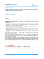
1 Overview
This part documents the commands and responses that are defined in the client protocol
implemented by the 1-Wire Automation Server.
2 Protocol Data
Once a client is connected to the server, the client and the server transfer data bytes to
each other. Data in either direction is UTF-8 encoded and represents a stream of Unicode
characters.
The server processes received data bytes through a number of stages to produce a single
line of text. A text line contains zero or more commands and is described by the
Command Text Line syntax block (see section “Command and Response Line” below).
The stages are:
1. UTF-8 decoder: The incoming stream of data bytes is decoded to a stream of Unicode
characters. The Unicode characters are buffered. When an end-of-line (EOL) marker
arrives, the buffer is passed to the next stage.
2. Tokenizer: During this stage, groups of consecutive
transformed into syntactical elements called tokens.
Unicode
characters
are
3. Parser: Tokens must be sequenced according to syntax rules so they form a valid
Command Text Line. The parser applies these syntax rules to the stream of tokens.
During this stage each command that occurs in the line is added to the command
queue.
Errors can occur at each stage. If verbose output is enabled, the server prints useful
information in case of an error.
The server's command processor implements this level of complexity in order to cope
with all possible input. A client may send all kinds of data, including utter gibberish. In all
cases, the server must persist.
A client is assumed to process incoming data bytes the same way. Therefore, the server
sends responses using the same syntax rules that apply to commands. Nevertheless, the
client can usually implement a less complex model of processing since the server always
formats its responses deterministically. When the server sends a response, it never uses
tabulation characters, always space characters. A response never contains multiple
consecutive space characters, thus in places where whitespace is required the server
always emits one space character.
UTF-8 Decoder
The UTF-8 decoder converts 1..4 data bytes to a Unicode character.
Note that UTF-8 is a superset of ASCII 7-bit, thus 1-byte values 0..127 are the same for
UTF-8 and ASCII.
User Manual – Part 2
5
1-Wire Automation Server v1.1.0
Tokenizer
The tokenizer transforms the stream of Unicode characters into elements called tokens.
Each token represents one or more consecutive Unicode characters. Note that all
characters are subjected to tokenization; never will a character be discarded.
Tokens are the most basic syntactical building blocks and greatly determine the overall
syntax of commands and responses.
Label Token
A label is composed of one or more characters:
▪
First character: 'A'..'Z', 'a'..'z', or '_'.
▪
Consecutive characters: 'A'..'Z', 'a'..'z', '0'..'9', '_'.
Labels are case-insensitive; “Dog”, “DOG”, and “dog” or interpreted the same.
Example labels:
piosensed
mnu3
_the_label
_45_minutes_
Number Token
A number is composed of one or more characters:
▪
First character: '0'..'9'.
▪
Consecutive characters: '0'..'9', 'A'..'Z', 'a'..'z', '_'.
Note that not all letters produce a valid number. Underscores can be inserted to augment
the readability of a number.
The last character determines the numeral system:
▪
Decimal: 'd' or 'D'.
▪
Hexadecimal: 'h' or 'H'.
▪
Binary: 'b' or 'B'.
The default is decimal.
Numbers are case-insensitive. Leading zeroes or allowed. The valid range of values is
0..4294967295 (FFFFFFFFh).
Examples:
125
10_1011_1000_B
0Fc8Eh
1234d
String Token
A string token represents characters between two double quote characters (").
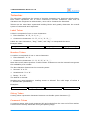
Comment Token
A comment starts with a hash character (#) and ends before the next end-of-line marker.
Comments are always discarded during the parsing stage.
6
User Manual – Part 2
1-Wire Automation Server v1.1.0
Comments come in handy when you put commands in a text file and you want to add
useful remarks to the commands. For example:
# Add AbioWire adapter. Let the server determine which interface to use,
# i2c-dev or BSC.
adapter "ow" add bscdetect abiowire
Character Token
This token represents a single Unicode character. The tokenizer assigns a character token
to every Unicode character that doesn't fit in any of the other tokens.
Examples:
▪
Space character, code 32.
▪
Tabulation character, code 9.
▪
Carriage return, code 13.
▪
Line feed, code 10.
▪
Colon, code 58.
Note that carriage return and line feed are end-of-line markers.
Parser
The parser checks the stream of tokens for valid syntax. Valid syntax is documented with
syntax flow diagrams. If a token doesn't fit in any flow, a syntax error occurs.
Space and tabulation character tokens act as delimiters between other tokens. A
command may contain multiple space and tabulation characters consecutively.
The parser always discards comment tokens. Note that a comment always concludes a
text line.
User Manual – Part 2
7
1-Wire Automation Server v1.1.0
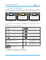
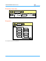
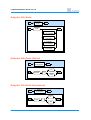
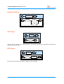
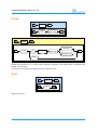
3 Syntax Flow Diagrams
Commands and responses are represented with syntax flow diagrams. These diagrams
are hierarchical in nature. The macro block element embodies the concept of hierarchy.
Macro
block
IN
OUT
Macro
block
IN
OUT
IN
Macro
block
OUT
Diagram
Diagram
Diagram
Client command syntax
diagram
Client response syntax
diagram
Client command and
response syntax diagram
The background color indicates whether the diagram applies to a command, a response,
or both.
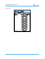
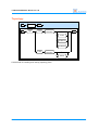
The diagrams are composed of elements:
dev
Label token
START
:
Character token (literal)
END
End of a text line
13
Character token (code)
IN
Entry to macro block
port
"..."
Description
#...
Adapter
ID
Number token
OUT
Comment token
Exit from macro block
Next element, one or
more blank[1] characters
allowed/required[2]
String token
BL
Next element, no blank[1]
characters allowed
Macro block
[1]
Space characters (32) and tabulation characters (9).
[2]
This depends on which elements the arrow connects.
8
Start of a text line
User Manual – Part 2
1-Wire Automation Server v1.1.0
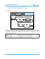
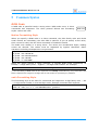
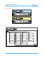
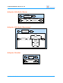
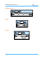
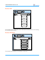
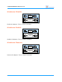
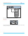
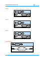
4 Command and Response Line
Command Text Line
START
COMMAND LINE
END
;
START
id
id
#...
COMMAND
13
10
END
10
As mentioned earlier in section “Protocol Data” above, the server decodes and buffers
incoming UTF-8 characters until an end-of-line marker comes in (stage 1), after which
the resulting so-called command text line is tokenized (stage 2) and parsed (stage 3).
Example command text lines:
uch purge
adapter 1 enum
# Enumerate the first 1-Wire adapter
hw enum ; block ; dump
# Enumerate all, dump results when finished
dev "28-40CBBB2" add ; dev "28-40CBBB2" attr poll=on,60000
User Manual – Part 2
9
1-Wire Automation Server v1.1.0
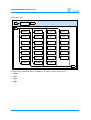
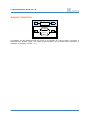
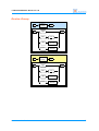
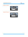
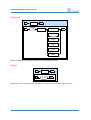
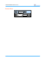
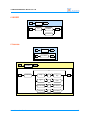
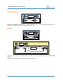
Command
IN
COMMAND
OUT
IN
ADAPTER
CTRL
LU
U421
ATTR
DEV
NPD
U451
AUTH
DUMP
PORT
UCH
BLOCK
FF32
QUIT
VERSION
CANCEL
FF34
REPORT
W1
CH
HW
TOPO
WAIT
CLOSE
LICENSE
U401
OUT
The following commands aren't available in the free version of the server:
▪
auth
▪
npd
▪
port
▪
topo
10
User Manual – Part 2
1-Wire Automation Server v1.1.0
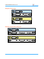
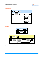
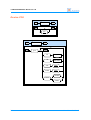
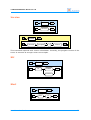
Response Text Line
START
RESPONSE LINE
id
START
id
END
RESPONSE
13
10
END
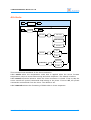
Response
IN
RESPONSE
OUT
IN
DETECT
LICENSE
DEV
PROBE
DONE
UNTIE
ENUM
VERSION
OUT
The responses the server produces.
User Manual – Part 2
11
1-Wire Automation Server v1.1.0
5 Common Syntax
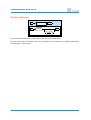
ROM Code
A ROM code is specified inside a string token. ROM codes occur in client
commands and responses. The client protocol defines two formatting
styles: native and owfs.
"..."
ROM code
Native Formatting Style
When you specify a ROM code in a client command, the 8-bit family code and 48-bit
serial number are mandatory, the 8-bit CRC is optional. If you do specify a CRC value,
then it must be valid, else the client command is considered invalid.
The ROM code resides in a string token. The values are hexadecimal digits, leading
zeroes are allowed. The values must be separated by hyphen characters. Other
characters including whitespace are not permitted.
hw
hw
hw
hw
hw
probe
probe
probe
probe
probe
"20-00000014C3CF-0E"
"20-14C3CF-E"
"20-00000014C3CF"
"20-14C3CF"
"1-16707B5B"
When the server returns a client response, it formats ROM codes consistently as
follows[1]: 2-digit family code → hyphen → 12-digit serial number. For example:
probe ch "usb-4-2":1:1 "20-00000014C3CF" present
[1]
The formatting of ROM codes in the responses from Dump commands may vary. Remember that
these responses are subject to change and are not meant for processing by software.
owfs Formatting Style
This formatting style is the same for commands and responses: 2-digit family code → dot
→ 12-digit serial number in reversed byte-order. Example command and response:
hw probe "26.48496B010000"
probe ch "usb-1-2":1:1 "26.48496B010000" present
12
User Manual – Part 2
1-Wire Automation Server v1.1.0
Adapter Identifier
IN
Adapter ID
OUT
adapter
IN
OUT
"..."
name
An adapter can be identified with its name or its number. If a string token is present, it
represents an adapter name. The name is case-sensitive. If a number token is present, it
indicates an adapter number (1..).
User Manual – Part 2
13
1-Wire Automation Server v1.1.0
Adapter-Controller
IN
IN
IN
IN
A:C
OUT
BL
Adapter ID
A:C
:
BL
controller
OUT
controller
OUT
OUT
BL
"..."
adapter
:
BL
Adapter-Controller-Channel
IN
IN
IN
IN
14
A:C:C
Adapter ID
A:C:C
"..."
adapter
OUT
BL
:
BL
controller
BL
:
BL
channel
OUT
channel
OUT
OUT
BL
:
BL
controller
BL
:
BL
User Manual – Part 2
1-Wire Automation Server v1.1.0
Port Identifier
IN
Port ID
"..."
IN
OUT
BL
ROM code
IN
Port ID
"..."
IN
ROM code
:
BL
port
OUT
port
OUT
OUT
BL
:
BL
Sensor Identifier
IN
SENSOR
ID
OUT
IN
ds18s20
ds1822
ds2780
max31826
ds2406
ds2438
ds2755
max31850
ds28e04
ds18b20
ds2740
ds2781
ds2423
ds2408
ds2413
ds28ea00
ds2450
ds2760
ds1825
OUT
User Manual – Part 2
15
1-Wire Automation Server v1.1.0
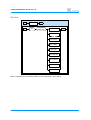
Short Response Identifier
IN
IN
SHORT
RSP ID
OUT
sensedt
all
year
hour
sensorid
month
minute
valid
day
second
temp
aind
tchot
vad
piosensed
tccold
vdd
pioset
tcfault
vin
pioact
tcunconn
cur
piocnt
tcopen
curacc
rstz
tcgnd
aina
cntra
tcvcc
ainb
cntrb
adpins
ainc
pwrmode
OUT
16
User Manual – Part 2
1-Wire Automation Server v1.1.0
Device Group
IN
Device
Group
IN
npd
uch
OUT
uch
ch
A:C:C
port
Port ID
IN
Device
Group
IN
npd
uch
User Manual – Part 2
OUT
OUT
OUT
uch
ch
A:C:C
port
Port ID
17
1-Wire Automation Server v1.1.0
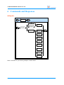
6 Commands and Responses
Adapter
IN
ADAPTER
OUT
"..."
IN
adapter
ADAPTER
ADD
name
Adapter ID
ADAPTER
REMOVE
OUT
ADAPTER
ENABLE
ADAPTER
DISABLE
ADAPTER
ATTR
DETECT
ENUM
UNTIE
PROBE
Base command for performing adapter-related tasks.
18
User Manual – Part 2
1-Wire Automation Server v1.1.0
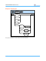
Adapter Add
IN
ADAPTER
ADD
IN
add
OUT
"..."
serial
serial path
OUT
"..."
i2cdev
bsc
ADAPTER
ADD SERIAL
i2c-dev path
ADAPTER
ADD I2C
bsc
bscdetect
enet
tmex
"..."
hostname
type
port
number
This client command adds a 1-Wire adapter. The arguments following the add label
describe one or more device nodes that make up a 1-Wire adapter.
If an adapter name is specified, it must not match any existing adapter name.
If no adapter name is specified, the server generates a unique adapter name. The server
always generates a unique name for dynamically added adapters like the DS9490.
The Adapter Add client command is one of a handful of commands that are executed
immediately instead of being queued.
User Manual – Part 2
19
1-Wire Automation Server v1.1.0
Adapter Add I2C
IN
ADAPTER
ADD I2C
IN
OUT
OUT
ds2482
slave ad
abiowire
mnu
mnu0
mnu1
mnu2
mnu3
This syntax describes one or more I2C slaves that reside on the same I2C bus and make
up a single adapter. Any combination is allowed, as long as no I2C slave addresses
overlap with already defined I2C slaves on the same I2C bus. Each I2C slave is reflected
by a device node.
The ds2482 label is used for DS2482-100 and DS2482-800 controllers. The server
distinguishes between these controllers when the built-in DS2482 driver is enabling the
chip.
The abiowire label covers AbioWire and AbioWire+ adapters. These adapters are
software-compatible. The label results in the addition of three device nodes.
Labels mnu, mnu0, mnu1, mnu2 and mnu3 target m.nu 1-Wire adapters.
20
User Manual – Part 2
1-Wire Automation Server v1.1.0
Adapter Add Serial
IN
IN
ADAPTER
ADD SERIAL
OUT
ds2480
OUT
ds9097u
ha7e
ha7s
axicat
uart0
ADAPTER
ADD SERIAL
uart1
twi
ADAPTER
ADD I2C
ow
spu
This syntax describes a 1-Wire master with serial interface.
User Manual – Part 2
21
1-Wire Automation Server v1.1.0
Adapter Attribute
IN
ADAPTER
ATTR
IN
attr
OUT
OUT
ADAPTER
ATTR RECONN
ADAPTER
ATTR ENUM
ADAPTER
ATTR DETECT
ADAPTER
ATTR NAME
Adapter Attribute Detect
IN
ADAPTER
ATTR DETECT
OUT
on
IN
detect
=
OUT
off
Adapter Attribute Enumerate
IN
ADAPTER
ATTR ENUM
OUT
on
IN
enum
=
OUT
off
22
User Manual – Part 2
1-Wire Automation Server v1.1.0
Adapter Attribute Name
IN
IN
ADAPTER
ATTR NAME
name
OUT
"..."
=
adapter
OUT
Adapter Attribute Reconnect
IN
ADAPTER
ATTR RECONN
OUT
,
IN
reconn
interval
=
OUT
on
off
Adapter Disable
User Manual – Part 2
IN
ADAPTER
DISABLE
OUT
IN
disable
OUT
23
1-Wire Automation Server v1.1.0
Adapter Enable
IN
ADAPTER
ENABLE
OUT
IN
enable
OUT
IN
ADAPTER
REMOVE
OUT
IN
remove
OUT
Adapter Remove
24
User Manual – Part 2
1-Wire Automation Server v1.1.0
Attribute
IN
IN
ATTR
attr
OUT
OUT
tscale
celsius
=
fahrenheit
kelvin
on
cancel
=
off
native
romcode
=
owfs
This command sets attributes of the client connection.
Label tscale select the temperature scale that is applied when the server formats
temperature values in sensor data strings and short responses. The default is Celsius.
Label cancel influences behavior when the client connection is closed. If set to on, the
server cancels all queued commands that belong to the client. If set to off, all queued
commands are detached from the client. The default is off.
Label romcode selects the formatting of ROM codes in client responses.
User Manual – Part 2
25
1-Wire Automation Server v1.1.0
Authentication
IN
AUTH
IN
auth
OUT
"..."
"..."
username
password
OUT
Block
IN
IN
BLOCK
OUT
block
OUT
Cancel
IN
IN
CANCEL
OUT
cancel
OUT
all
26
User Manual – Part 2
1-Wire Automation Server v1.1.0
Channel
IN
IN
CH
OUT
ch
A:C:C
DG MOVE
OUT
DG CLEAR
DETECT
ENUM
UNTIE
PROBE
Base command for performing tasks on the specified channel.
Close
IN
IN
CLOSE
close
OUT
OUT
When the server executes this command, it closes the connection with the client.
User Manual – Part 2
27
1-Wire Automation Server v1.1.0
Controller
IN
CTRL
OUT
IN
ctrl
A:C
DETECT
OUT
ENUM
UNTIE
PROBE
Detect
IN
DETECT
IN
detect
IN
DETECT
OUT
IN
detect
OUT
OUT
ctrl
A:C
done
OUT
done
Run the detection procedure for a controller, optionally confined to a single channel.
This macro command is expanded at the controller level.
28
User Manual – Part 2
1-Wire Automation Server v1.1.0
Device
IN
IN
DEV
dev
OUT
"..."
ROM code
DEV ADD
OUT
DEV REMOVE
DEV MOVE
DEV SENSE
DEV PIO
DEV RGBCTRL
DEV SWITCH
DEV ATTR
DEV LOCATE
Base command for performing tasks on the specified 1-Wire slave.
User Manual – Part 2
29
1-Wire Automation Server v1.1.0
Device Add
IN
IN
DEV ADD
OUT
add
OUT
ds2409
hbh4
ds1825
max31826
max31850
This command adds a 1-Wire slave. If the 1-Wire slave is already present in the topology,
the command will be ignored.
Device Attribute
IN
DEV ATTR
IN
attr
OUT
OUT
DEV ATTR
POLL
DEV ATTR
FORCE PORTS
DEV ATTR
POWER MODE
DEV ATTR
DESCRIPTION
This command sets attributes of the specified 1-Wire slave.
30
User Manual – Part 2
1-Wire Automation Server v1.1.0
Device Attribute Description
IN
DEV ATTR
DESCRIPTION
IN
descr
OUT
"..."
=
description
OUT
Device Attribute Force Ports
IN
DEV ATTR
FORCE PORTS
OUT
on
IN
forceports
=
OUT
off
Device Attribute Power Mode
IN
DEV ATTR
POWER MODE
OUT
parasite
IN
pwrmode
=
OUT
external
User Manual – Part 2
31
1-Wire Automation Server v1.1.0
Device Attribute Poll
DEV ATTR
POLL
IN
OUT
,
interval
=
IN
OUT
on
off
Device Locate
IN
DEV LOCATE
IN
locate
OUT
OUT
Device Located
IN
DEV LOCATED
IN
dev
"..."
OUT
ROM code
located
nonpresent
OUT
Device
Group
32
User Manual – Part 2
1-Wire Automation Server v1.1.0
Device Move
User Manual – Part 2
IN
DEV MOVE
IN
move
OUT
Device
Group
OUT
33
1-Wire Automation Server v1.1.0
Device PIO
IN
PIO MASK
IN
OUT
OUT
pio
IN
DEV PIO
IN
pio
OUT
OUT
on
PIO MASK
off
PIO MASK
set
mask
clear
mask
strobe
rstz
reset
34
User Manual – Part 2
1-Wire Automation Server v1.1.0
Device Remove
IN
DEV REMOVE
IN
remove
OUT
OUT
delay
This command remove the 1-Wire slave with the given ROM code.
If a non-zero delay is present, the server will wait for this number of milliseconds before
removing the 1-Wire slave.
User Manual – Part 2
35
1-Wire Automation Server v1.1.0
Device RGB Controller
IN
COLOR MASK
OUT
,
IN
value
=
OUT
on
off
IN
DEV RGBCTRL
IN
rgbctrl
OUT
OUT
red
=
COLOR MASK
green
=
COLOR MASK
blue
=
COLOR MASK
clear
36
User Manual – Part 2
1-Wire Automation Server v1.1.0
Device Sense
IN
DEV SENSE
IN
sense
OUT
OUT
force
rsp
=
SHORT
RSP ID
Device Sensed
IN
DEV SENSED
IN
dev
User Manual – Part 2
OUT
"..."
ROM code
sensed
SENSOR
ID
"..."
sensor data
OUT
37
1-Wire Automation Server v1.1.0
Device Switch
IN
DEV SWITCH
OUT
IN
switch
on
OUT
off
DG Clear
IN
DG CLEAR
IN
clear
OUT
OUT
Clear a device group. All 1-Wire slaves in the device group are removed, thus become
unknown to the server.
DG Move
IN
DG MOVE
IN
move
OUT
Device
Group
OUT
Move a device group to another location in the topology.
38
User Manual – Part 2
1-Wire Automation Server v1.1.0
Done
IN
IN
DONE
done
OUT
OUT
This response is generated when a command with an identifier has completed.
User Manual – Part 2
39
1-Wire Automation Server v1.1.0
Dump
IN
DUMP
OUT
dump
IN
OUT
topo
dn
Enumerate
IN
ENUM
IN
enum
IN
ENUM
OUT
IN
enum
OUT
OUT
ch
A:C:C
done
OUT
done
Enumerate 1-Wire slaves residing behind a channel.
This macro command is expanded at the channel level.
40
User Manual – Part 2
1-Wire Automation Server v1.1.0
FF32
IN
FF32
IN
ff32
IN
FF34
IN
ff34
OUT
FF
OUT
FF34
OUT
FF
OUT
FF
IN
IN
User Manual – Part 2
FF
ow
OUT
ad
"..."
pin
OUT
41
1-Wire Automation Server v1.1.0
Hardware
IN
HW
IN
hw
OUT
HW
REMOVE
OUT
HW
ENABLE
HW
DISABLE
DETECT
ENUM
UNTIE
PROBE
42
User Manual – Part 2
1-Wire Automation Server v1.1.0
Hardware Attribute
IN
HW
ATTR
IN
attr
OUT
OUT
HW ATTR
ENUM
HW ATTR
DETECT
Set hardware attributes.
Hardware Attribute Detect
IN
HW ATTR
DETECT
OUT
on
IN
detect
=
OUT
off
Turn on or off automatic detection for all adapters.
Hardware Attribute Enumerate
IN
HW ATTR
ENUM
OUT
on
IN
enum
=
OUT
off
Turn on or off automatic enumeration for all adapters.
User Manual – Part 2
43
1-Wire Automation Server v1.1.0
Hardware Disable
IN
IN
HW
DISABLE
disable
OUT
OUT
Enable all adapters. This is a macro command.
Hardware Enable
IN
IN
HW
ENABLE
enable
OUT
OUT
Disable all adapters. This is a macro command.
Hardware Remove
IN
IN
HW
REMOVE
remove
OUT
OUT
Remove all adapters. This is a macro command.
44
User Manual – Part 2
1-Wire Automation Server v1.1.0
LibUSB
IN
LU
OUT
IN
lu
enable
OUT
disable
License
IN
LICENSE
IN
license
IN
LICENSE
OUT
IN
license
OUT
OUT
key
type
licensee
company
User Manual – Part 2
BL
BL
BL
BL
=
=
=
=
BL
"..."
key
BL
OUT
"..."
type
BL
"..."
licensee
BL
"..."
company
45
1-Wire Automation Server v1.1.0
NPD
IN
NPD
OUT
npd
IN
DG MOVE
OUT
DG CLEAR
Base command for performing tasks on the non-present devices.
Port
IN
IN
PORT
port
OUT
Port ID
DG MOVE
OUT
DG CLEAR
Base command for performing tasks on a specified hub port.
46
User Manual – Part 2
1-Wire Automation Server v1.1.0
Probe
IN
PROBE
IN
PROBE
IN
probe
OUT
"..."
ROM code
OUT
OUT
present
IN
probe
ch
"..."
A:C:C
OUT
ROM code
nonpresent
done
Probe the presence of a 1-Wire slave behind a channel. The ROM code represents the
target 1-Wire slave.
This macro command is expanded at the channel level.
Quit
IN
IN
QUIT
quit
OUT
OUT
Quits the server.
User Manual – Part 2
47
1-Wire Automation Server v1.1.0
Report
IN
REPORT
OUT
add
REPORT
SENSED
report
IN
OUT
remove
REPORT
TOPO
REPORT
HW
This command controls the unsolicited responses the server sends to the client. Use the
command to add and remove pieces of information the client wants to receive.
Report Sensed
IN
IN
REPORT
SENSED
OUT
sensed
OUT
[1]
[1]
always
diff
all
SENSOR
ID
[1]
48
Only with report add
dev
"..."
ROM code
User Manual – Part 2
1-Wire Automation Server v1.1.0
Report Topology
IN
REPORT
TOPO
IN
topo
IN
REPORT
HW
OUT
OUT
Report Hardware
IN
User Manual – Part 2
hw
OUT
OUT
49
1-Wire Automation Server v1.1.0
Topology
IN
IN
TOPO
topo
OUT
save
"..."
OUT
filename
utf8
utf16le
utf16be
load
"..."
filename
force
Commands for loading and saving topology files.
50
User Manual – Part 2
1-Wire Automation Server v1.1.0
UCH
IN
IN
UCH
OUT
uch
UCH ADD
OUT
UCH PURGE
uch
UCH REMOVE
UCH ATTR
DG MOVE
DG CLEAR
Base command for performing tasks on unallocated channels.
UCH Add
IN
IN
UCH ADD
add
OUT
OUT
Add a new unallocated channel. The newly added unallocated channel is empty, meaning
it contains no 1-Wire slaves.
User Manual – Part 2
51
1-Wire Automation Server v1.1.0
UCH Attribute
IN
UCH ATTR
IN
attr
OUT
nid
count
=
OUT
Set attributes of an unallocated channel. Currently, you can set the number of nonidentification slaves to be taken into account during a detection procedure.
UCH Purge
IN
UCH PURGE
IN
purge
OUT
OUT
Client command UCH Purge removes all empty unallocated channels.
Empty unallocated channels usually pile up when a 1-Wire adapter appears and
disappears regularly while it is set to enumerate automatically upon arrival. The
enumeration typically finds all 1-Wire slaves that are stored in one or more unallocated
channels and moves these slaves behind the adapter's channel or channels, resulting in
empty unallocated channels. The idea is to execute the UCH Purge command
periodically in such case.
52
User Manual – Part 2
1-Wire Automation Server v1.1.0
UCH Remove
IN
UCH REMOVE
IN
remove
OUT
OUT
Remove an unallocated channel. If 1-Wire slaves reside in the unallocated channel, the
server moves them to the non-present devices first.
Untie
IN
UNTIE
IN
untie
IN
UNTIE
OUT
IN
untie
OUT
OUT
ch
A:C:C
done
OUT
done
Untie all 1-Wire slaves residing behind a channel and move them to a new unallocated
channel.
This macro command is expanded at the channel level.
User Manual – Part 2
53
1-Wire Automation Server v1.1.0
U401
IN
U401
IN
u401
IN
U421
IN
u421
IN
U451
IN
u451
OUT
USBMICRO
OUT
U421
OUT
USBMICRO
OUT
U451
OUT
USBMICRO
OUT
USBMICRO
IN
USBMICRO
OUT
default
IN
"..."
ow
"..."
pins
OUT
serial number
54
User Manual – Part 2
1-Wire Automation Server v1.1.0
Version
IN
VERSION
IN
version
IN
VERSION
OUT
IN
version
OUT
OUT
program
BL
=
BL
"..."
version
OUT
This command responds with version information. Currently, the program version of the
server is returned as a major-minor-micro triplet.
W1
IN
W1
IN
w1
OUT
enable
OUT
disable
Wait
IN
IN
User Manual – Part 2
WAIT
wait
OUT
ms
OUT
55
1-Wire Automation Server v1.1.0
7 Legal Information
Disclaimer
Axiris products are not designed, authorized or warranted to be suitable for use in space,
nautical, space, military, medical, life-critical or safety-critical devices or equipment.
Axiris products are not designed, authorized or warranted to be suitable for use in
applications where failure or malfunction of an Axiris product can result in personal
injury, death, property damage or environmental damage.
Axiris accepts no liability for inclusion or use of Axiris products in such applications and
such inclusion or use is at the customer's own risk. Should the customer use Axiris
products for such application, the customer shall indemnify and hold Axiris harmless
against all claims and damages.
Trademarks
“Maxim Integrated” is a trademark of Maxim Integrated Products, Inc.
“1-Wire” and “iButton” are registered trademarks of Maxim Integrated Products, Inc.
“Raspberry Pi” is a trademark of the Raspberry Pi Foundation.
All product names, brands, and trademarks mentioned in this document are the property
of their respective owners.
8 Contact Information
Official website: http://www.axiris.eu/
56
User Manual – Part 2