1
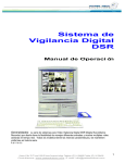
HomeGuard
Real time 4 video surveillance recording card
User’s Manual
_____________________________________________________________________________
FEDERAL COMMUNICATIONS COMMISSION
This device complies with Part 15 of the FCC Rules Operation is subject to
the following two conditions: this device may not cause harmful interference,
and (2) this device must accept any interference received, including
interference that may cause undesired operation.
This equipment has been tested and found to comply with the limits for a
Class B Digital Device, pursuant to part 15 of the FCC Rules. These limits
are designed to provide reasonable protection against harmful interference in
a residential installation. This equipment generates, uses and can radiated
radio frequency energy and, if not installed and used in accordance with the
instruction, may cause harmful interference to radio communication.
However, there is no grantee that interference will not occur in a particular
installation. If this equipment does cause harmful interference to radio or
television reception, which can be determined by tuning the equipment off
and on, the user is encouraged to try to correct the interference by one or
more of the following measures:
-Reorient or relocate the receiving antenna.
-Increase the separation between the equipment and receiver.
-Connect the equipment into an outlet on a circuit different from that to
which the receiver is connected.
-Consult the dealer or an experienced radio/TV technician for help.
Notice: Changes or modifications not expressly approved by the party
responsible for compliance could void the user’s authority to operate the
equipment.
CE DECLARATION
This device complies with CE . These limits are designed to provide reasonable protection against
harmful interface in a residential installation.
Printed in TAIWAN R.O.C No.01110104
All contents are subject to change without notice.
All trademarks are the property of their respective owner
I
Table of Contents
Chapter 1. Overview ----------------------------------------------------------1.1.
1.2.
1.3.
1.4.
1.5.
1
Introduction -----------------------------------------------------------------Features ---------------------------------------------------------------------Specifications --------------------------------------------------------------Minimal System Requirements ----------------------------------------Package Contents ---------------------------------------------------------
1
1
2
2
2
Chapter 2. Installation --------------------------------------------------------
3
2.1.
2.2.
2.3.
Hardware Installation ----------------------------------------------------Driver Installation ---------------------------------------------------------Application Software Installation ---------------------------------------
3
3
4
Chapter 3. Function Operating ------------------------------------------- 5
3.1.
3.2.
3.3.
3.4.
3.5.
3.6.
3.7.
Starting ----------------------------------------------------------------------Display ----------------------------------------------------------------------Motion Detection ----------------------------------------------------------Recording -------------------------------------------------------------------Playback the Video -------------------------------------------------------Utility --------------------------------------------------------------------------DSR Configuration ---------------------------------------------------------
5
5
7
10
17
23
30
Chapter 4. Trouble Shooting ------------------------------------------------ 32
_______________________________________________________________________________
II
Chapter 1. Overview
1.1 Introduction
Congratulations on your purchase of “HomeGuard”! You can now
protect your home with the powerful PCI surveillance capture card. The
device supports real time display monitoring and simultaneous recording
for up to 4 security cameras. Powerful security functions includes motion
detection recording, remote internet monitoring access, video file
database management system. You can protect your home and family
through the internet where ever you are.
1.2 Features
4 video simultaneously display/recording in one board
Display capability
One screen/Four screen/Sequence display mode support
Full screen display support
Camera ID, date/time status OSD window display
Recording capability
Instant/Schedule/Alarm/Pre-alarm recording
Pre-Alarm recording to record before alarm event has happened
Recording frame rate adjustable
Linear or Circular(overwrite) mode support
Multiple camera independent recording
Time stamp support
Camera ID, start date/time logged into database
Audio recording support by sound card or HomeGuard
Recording drive selectable
Motion detection
Sensitivity setting
Detection interval setting
Recording time extension setting
Detection area setting
Playback capability
Powerful video search engine, It can be searched by time mode,
date mode, event mode, camera ID and so on.
Scroll bar to search the video you needed
Absolute date/time and length display
_____________________________________________________________
1
Chapter 1. Overview
Playback speed control
Rewind/Replay support
Snapshot support during playback
Print support for image capture
Zoom support
Security management : Password protection in program start up,
configuration setting and program off. Allows user to enter this
program by offering different password with different authorization
level
Remote monitoring support
1.3 Specifications
Resolution : 640 x 480
Display frame rate : Up to 30fps(NTSC), 25fps(PAL)
Recording frame rate : Up to 30fps(NTSC), 25 fps(PAL)
Recording mode -- Super mode : 640 x 480 (NTSC/PAL);
High mode : 384x288(PAL), 320x244(NTSC); Low mode :
192x144(PAL), 160x120(NTSC)
Analog video : 4 analog video input BNC port,
Video system : NTSC, PAL multi system support
Recording file size 400MB per day(based on low mode and 1fps)
Remote streaming video file format : MPEG4
Compression type : MJPEG
1.4 Minimum System Requirements
Pentium III 800 or above
128MB of RAM or above
Microsoft Windows 98SE/2000/ME/XP
One PCI 2.1 bus slot
CD-ROM drive
Sound card (option for audio capture)
1.5 Package Contents
HomeGuard PCI board
Manual
Software CD
_____________________________________________________________
2
Chapter 2. Installation
2.1 Hardware Installation
2.1.1. Shut down your computer before you plug in HomeGuard
2.1.2. Open computer case
2.1.3. Plug HomeGuard board in a free PCI slot
2.1.4. Connect external camera video source
2.1.5. Connect microphone input if you need
2.2. Driver Installation
2.2.1. Please make sure HomeGuard is plugged in the computer
already
2.2.2. Turn on the computer
2.2.3. System automatically detects the new hardware(Multimedia Video
Controller),
Please choose " Install from a list or specific location
(Advanced) " Click " Next "
2.2.4. (a) Please choose “Search for the best driver in these
locations.
(b) Please choose “Include this location is the search: “
(c) Insert “Multimedia Installation Kit “ CD-ROM into your
CD-ROM drive
(d) Type “E:\ HomeGuard\Driver\win2k_XP“ if you are using
Win2k or XP;
Type “E:\ HomeGuard\Driver\win98_ME“ if you are using
Win98 or ME;
(assuming CD-ROM drive is E drive), Click " Next "
2.2.5. When Windows XP show message about this software didn’t pass
Windows Logo, please click “Continue Anyway ”
(HomeGaurd is thoroughly tested by engineers, and it will not
_____________________________________________________________
3
Chapter 2. Installation
cause harm to your system)
2.2.6. Complete the Video Capture driver installation
Click " Finish "
2.2.7. System automatically detect new hardware (Multimedia Controller)
Please choose " Install from a list or specific location
(Advanced) " Click " Next "
2.2.8. (a) Please choose “Search for the best driver in these
locations.
(b) Please chose “Include this location is the search: “
(c) Type “E:\HomeGuard\Driver\win2k_XP“ if you are using
Win2k or XP;
Type “E:\ HomeGuard\Driver\win98_ME“ if you are using
Win98 or ME;
(assuming CD-ROM drive is E drive), Click " Next "
2.2.9. When Windows XP show message about this software didn’t pass
Windows Logo, please click “Continue Anyway ”
2.2.10. Complete the Audio Capture driver installation
Click " Finish "
2.3. Application Software Installation
2.3.1. Please insert “Multimedia Installation Kit “ CD-ROM into your
CD-ROM drive; Run “E:\ HomeGuard\AP software\setup.exe “;
(assuming CD-ROM drive is E drive), Click " Next "
2.3.2. Welcome; Click “Next”
2.3.3. Information; Click “Next”
2.3.4. Select Component;
NTSC : Please choose “Pico2000_104(NTSCApplication)
PAL : Please choose “Pico2000_104(PALApplication)
Click “Next”
2.3.5. The Options key information ; Click “Next”.
2.3.6. Choose Destination Location; Click “Next”.
2.3.7. RegSvr32; Click “OK”.
2.3.8. RegSvr32; Click “OK”.
2.3.9. RebootDialog; Click “OK” to restart system.
2.3.10. After restart system, please run “E:\ HomeGuard\AP
software\English Pack.exe “;
_____________________________________________________________
4
Chapter 3. Function Operating
3.1. Starting
3.1.1. Please click “Pico2000”
icon, after starting
application, you can see
main screen
3.1.2. Please click “Logon”, the
logon screen show,
please click “OK”
(Password is not required
in the first start up)
3.1.3. All functions active as shown
3.2. Display : A “DISPLAY” panel is implemented on the upper right hand
corner of the main screen so that the user can interact with
the unit more easily.
The “DISPLAY” panel consists of “display mode” buttons,
”camera” buttons and a “sequence” button respectively (see
_____________________________________________________________
5
Chapter 3. Function Operating
following Figure)
All of the push buttons have their individual built-in indicator
lights. Once the button is pressed, it toggles on and off with
the indicator light on and off to indicate its status
correspondingly.
Tip : You are able to know which camera(s) is/are being
displayed by the “DISPLAY” panel indicator lights, and
you can press the buttons on the “DISPLAY” panel to
enter your display input right away.
Tip : No camera button can be selected prior to the mode
selection. User should click on one of the display mode
button first.
3.2.1.
3.2.2.
1-Screen Mode
Click the 1-Screen mode button on the display control
panel to select this mode.
Only one camera can be selected for display.
Click the camera button to select camera to display in this
mode.
The down button will light up in yellow.
4-Screen Mode
Click the 4-Screen mode button on the display control panel
to select this mode.
Four cameras can be selected for display simultaneously.
Click the camera buttons to select camera(s) to display in
this mode.
_____________________________________________________________
6
Chapter 3. Function Operating
The down buttons will light up in yellow to indicate the
display status.
Rapid Zoom : You can jump to one-screen display mode
instantly.
Simply double-click on the desired image on
screen, and the image of that screen will be
zoomed to “one screen” mode immediately.
3.2.3. Full Screen Display
Click on the “Full Scrn” button on the lower right hand side
of the main screen to display the video(s) in full screen.
All the control panels and buttons will be hidden and only
videos will be displayed on the screen in order to fully utilize
the displaying area of the monitor.
Right-mouse click on any part of the full screen to return the
normal control panel display.
3.2.3.
Sequence
Click the “SEQ” button on the display control panel to toggle
the sequence function on or off.
The indicator of the button lights up in yellow to indicate the
sequence function.
The function of sequencing is effective for all display modes,
except for the 16-Screen mode.
The user can select individual camera(s) for sequencing
display.
Note: When the unit is in sequence mode, all the camera
selection buttons inside display panel will be inhibited.
You can click the “SEQ” button to toggle it off to re-gain
manual access of the camera selection.
3.3. Motion Detection
An advanced digital video-processing algorithm is used to implement
motion detection function in DSR.
The motion detection function is designed to automatically detect any
activities within a selected detection area(s), and to start recording of
that camera when activity is detected inside the detection area(s).
Right clicks the mouse button on the video screen of the camera you
_____________________________________________________________
7
Chapter 3. Function Operating
want to set motion detection.
A “Motion detection setting” dialog box will pop up for
motion detection setting.
3.3.1. Set Detection Area
Simply click on any spot to select/de-select the
grid(s) to form detection area(s) of any shape
in the video screen for motion detection.
The “Select all” button is used to rapidly select
the whole video screen for detection.
The “Clear all” button is used to de-select all
the selected areas.
3.3.2. Indicate the Detection Area
If you want the detection area to be presented
on the video screen during normal operation,
click the “Show at all time” button.
If you don want the detection area to be
presented in the video screen during normal
operation, click the “Not show” button.
3.3.3. Set Sensitivity for Motion Detection
Click the “Sensitivity setup” button to display the “Activity blocks”
for sensitivity setup.
The “activity blocks” will superimpose on the moving object to
highlight the activities on the video screen.
You can adjust the sensitivity by using the sensitivity control box.
Click the up arrow button to increase the sensitivity and click the
down arrow button to decrease the detection sensitivity
respectively.
The sensitivity value display inside the control box, which is an
arbitrary value, indicates the relative detection sensitivity.
Adjust the sensitivity by monitoring the “activity blocks” on the
screen to determine that the sensitivity is adjusted to an optimal
condition for motion detection and without false alarm.
User can check the “Show within detection area” button to confine
the “activity blocks” only to display within the detection areas you
have selected.
_____________________________________________________________
8
Chapter 3. Function Operating
3.3.4. Detection Interval
The occurrence of motion is detected by correlating the
successive frames of the video. The “Detection interval” control
box can adjust the detection interval between these successive
frames. The detection interval is in unit of 100mS.
The default value is at 200mS.
3.3.5. Recording Time Extension
The motion detected in the detection area(s) will be used as an
event to trigger the alarm recording of the corresponding camera.
Once the recording is started, it will continue with an extension
time even the motion is stopped.
This extension time can be adjusted by using the “Post motion
rec.” control box.
The time interval is in unit of second show inside the control box
and the default value is 3 seconds.
3.3.6. Enable the Motion Detection Function
Click the “Motion detection enable” box to enable the motion
detection function once you have set all the parameters.
(User can temporarily disable the motion detection by uncheck
the “Motion detection enable” box. All the settings of the motion
detection will stay unchanged, which let the user to enable the
motion detection back again afterward more easy).
Click the “Close” button; the corresponding camera button in the
display panel will light up with a yellow grid indicator to indicate
the motion detection function.
The detection area will be presented in the video screen if the “Show at all time” button is clicked.
Tips :
--Use motion detection recording instead of using schedule
_____________________________________________________________
9
Chapter 3. Function Operating
recording in order to effectively use of the recorder storage
space.
--Think of using the motion detection in the low activity area
and let DSR to monitor the area for you.
--Motion detection when works with the search engine allows
you to playback the useful video more easily.
--Set up the motion detection correctly to prevent too many
false alarms to happen.
--Think of using the alarm scheduler to arm the motion
detection so that it can start at say after office hour.
3.3.7. Alarm status indication
--The status indicators in the "Display" control buttons are for
motion detection status
indication.
--The indicator will light up if the
motion detection is enabled.
--There have three possible alarm
statuses, which are no alarm
set, alarm set but out of
scheduled time and alarm armed.
--Grey color of the indicator means
no alarm is set.
--Red color of the indicator means that the motion detection is
armed, the alarm recording can be triggered at any time.
--Blue color of the indicator means that the motion detection is
being set but the alarm scheduler inhibit the alarm to arm
when it is out of the scheduled time.
3.4. Recording
Storage Drive
For “Normal” mode of operation : Automatically detect available
fixed hard disk(s) in the unit for recording.
For “Archive mode of operation: Directly record into the active
removable hard disk in the unit
Notes: The active (selected) drive should be assigned properly before
the overall backup and restore operation is executed. Assign the
target drive inside the “Insert drive “message box
_____________________________________________________________
10
Chapter 3. Function Operating
by clicking the “Swap Drive “button while the system is
operated in “Archive” backup mode. Go to 3.6.4. “Option
Setting” chapter for further detail.
Types of Recording
According to the recording initiation method, four different types of
recording are available : Instant recording/Scheduled
recording/Alarm recording/Pre-alarm recording
Multiple Camera Recording
-- All cameras can be recorded independently.
-- Each camera will be recorded into individual video file(s).
--The camera ID, start date/time, and the recording mode of the
individual camera will be logged with database management.
Recorder Control Panel
There is a “RECORDER” panel to let the user
interact with the unit for recording control with
enough indication.
There are 4 camera buttons in the ‘RECORDER”
panel, all of which can be toggled on or off.
Each button provides different colors to indicate
different types of recording and the status.
The available indicator colors are red, light blue,
yellow and green respectively.
Only one type of recording is possible to each camera at one time
and the priority of the recording type is as the following table
respectively.
Red
: Alarm recording, which is initiated by the alarm input or
by motion detection.
Light blue : Indicate the Pre-alarm function of that camera.
Yellow
: Instant recording, which is initiated by clicking the
camera button on the recorder panel manually.
Green
: Scheduled recording, which is controlled and started
by the programmable timer.
3.4.1. Instant Recording
Instant recording is the most interactive way and easy to use
_____________________________________________________________
11
Chapter 3. Function Operating
recording method.
-- It is designed to start recording instantly to capture some
unexpected special events.
-- It works as a complement of the scheduled recording.
-- You can simply toggle on or off the video recording by clicking
the camera button on the “ RECORDER” panel.
--The down button with a yellow light indicator indicates that the
camera is under instant recording.
--Instant recording parameters of each camera can be
programmed.
--Please see the 3.6.3.4. section of Instant Recording Setting for
parameter setup.
Note : The instant recording video will be chopped into 15
minutes length files automatically in order to keep the
record files at an accessible size.
Tip : Instant recording can be used to work in a fast frame rate for
short time recording while scheduled recording is expected
to work in a lower frame rate for longer time recording.
3.4.2. Scheduled Recording
--A programmable timer is implemented for scheduled recording.
--DSR supports both weekday and weekend scheduled recording.
--The timer will start and stop scheduled recording automatically
according to your input.
--A green indicator indicates the camera, which is recording under
the timer control.
_____________________________________________________________
12
Chapter 3. Function Operating
--The default recording duration value is 0, which represents
infinity or continue recording.
--During schedule recording, you can manually over ride to instant
recording mode by pressing down the camera button on the
“RECORDER” Panel. The indicator will change to yellow to
indicate that the camera is under instant recording.
--However, it will automatically resume scheduled recording once
you click the camera button to turn off instant recording of that
camera. The indicator will then resume to green.
--Please see Scheduled Recording Setting in the
Utility->Recorder Setting section for the setup and
implementation example of the schedule recording.
Note : Only the logon username of “SUPER” can access the
utility for configuring settings of scheduled recording
parameters.
Note : The schedule recording video will be chopped into 15
minutes length files automatically in order to keep the
record files at an accessible size.
3.4.3. Alarm Recording
--Alarm recording will be triggered by the motion detection.
--Once the alarm is triggered by the motion detection, the
corresponding camera will start recording automatically.
--A red indicator indicates that the camera is now under alarm
recording.
--The alarm recording function of an individual camera can be
disabled; also the alarm recording duration and the frame rate
of each camera can be programmed individually.
--Please see the 3.6.3.3. section of Alarm Recording Setting for
the setup details.
Note : Only the logon username of “SUPER” can access the
utility for alarm enable and alarm recording parameter
settings.
_____________________________________________________________
13
Chapter 3. Function Operating
3.4.4. Pre-Alarm Recording
--Pre-alarm recording works together with the alarm recording,
which enables you to capture images before the alarm event is
happened.
--Pre-alarm allows images to be temporarily recorded for a short
period of time (1 to 60 second) at normal situation. Once an
alarm is being triggered, the pre-alarm images become
permanent files, which can be retrieved and playback.
--Using “Play Back” function can playback the pre-alarm images.
--The pre-alarm function is setup in the “Alarm”, “Recorder
Setting” inside “Utility”
--You can activate the pre-alarm function accordingly when the
alarm function is selected.
--Please see the 3.6.3.3. section of Pre-Alarm Recording Setting
for the setup details.
Note : Pre-alarm images are stored into two temporary files
alternatively under normal situation. Therefore, when alarm
is being triggered, there will be two pre-alarm files
accompanies with the alarm file.
Tip : Pre-alarm recording provides an effective way of using the
hard disk storage:
--The pre-alarm images will be kept in the hard disk
permanently only when an alarm is actually taken place.
-- It provides image before the alarm, you can review what is
happening before the alarm was being triggered and it use
lesser hard drive space than doing schedule recording at all
time.
3.4.5. Scheduled Alarm and Motion Detection
A programmable timer is implemented for scheduled alarm and
motion detection.
Please see the 3.6.3.3. section for the set up.
_____________________________________________________________
14
Chapter 3. Function Operating
3.4.6. Recording with Audio
HomeGuard provides audio function to one of the cameras for
recording. Click Utility->Option Setting->Audio Setting in Main
screen
User can install a microphone through sound card(Mic in)
connection or HomeGuard board(Mic in)
To setup audio recording, please refer to the attaching audio to
camera of the Utility->Option Setting->Audio Setting.
Before you can activate this function, you will need to have a
Sound board installed and properly configured to make sure
Microphone can record
Each card provides one audio channel that can be attached to
any selected camera(s) for recording.
3.4.7. Archive Mode
Click Utility->Option Setting->Backup in Main screen
Considering the total process of recording and backup of the
videos, we can come up with two different configurations:
Normal Mode - It will record video into the Fixed Hard Drive (s).
As required, you can backup the recorded video
to a Removable IDE drive via the Housekeeping
function from the Utility Menu. The raw copy of
video can optionally be deleted during the backup
process.
Archive Mode -It will record video into the assigned Removable
_____________________________________________________________
15
Chapter 3. Function Operating
IDE Hard Drive(s). When it is about full, it can be
removed from the recorder physically for
additional archiving to DAT or other backup media.
The DSR Digital Surveillance Recorder will
maintain continuous recording to an alternate
removable drive during the archiving operation.
When the videos inside a Removable drive are
obsolete, they can be erased immediately before
video recording is resumed on this drive.
The recording configuration of the DSR should be selected at the
very beginning of overall system operation.
The normal mode is set by default. To switch to the Archive mode,
please refer to the Backup Function of the Options Setting Menu.
You will need to have two removable IDE hard drives configured
in the DSR to support this mode of system operation.
3.4.8. Swap Drive
Swap Drive button will show on main screen after you choose
“Archive Mode” Make sure the system is properly setup with two
available ”Removable Hard drive” and there is a fixed hard drive
to support system operations.
Click the Swap Drive button in the Main Screen and then the
”Swap drive” message box will appear as shown in the following
Figure.
Click the down arrow in the Select drive dialog box next to the
Remove button to display the registered removable drive(s) for
removal and select the desired drive. Click Remove button and
_____________________________________________________________
16
Chapter 3. Function Operating
follow the pop up instruction to complete the REMOVE process.
The removed hard drive can put into another machine and the
entire drive can be back up (Archive) to other long term storage
media such as the DAT or equivalent device with huge storage
capacity but may not work as fast. This operation on a
dismounted drive can be down off-line (while the DSR is closed)
or in a separate PC workstation.
Re-insertion of Removable Drive
Click the Swap Drive button in the Main Screen and then the
“Swap drive” message box will appear as shown in Figure above.
Click the down arrow in the Select drive dialog box next to the
Insert button to display the registered removable drive(s) for
insertion and select the desired drive. Click Insert button and
follow the pop up instruction to complete the INSERTION
(RE-Insertion) process.
3.5. Playback the Video
Click the “PlayBack” button in the main screen to invoke the video player.
The video player provides interactive video search and frame operations
to playback the recorded video files.
_____________________________________________________________
17
Chapter 3. Function Operating
3.5.1. Playback the files which are stored inside local machine
--Select "Local" radio button in the top right hand corner of the
video player to playback the files stored inside local machine.
--Available server name with recorded video inside the local
machine become selectable by clicking the down arrow in the
server selection control.
--Available camera under the selected server name become
selectable by clicking the down arrow button in the camera
selection control.
--Available date under the selected camera become selectable by
clicking the down arrow button in the date selection control.
--Available video will be populated into the video search engine.
--User click the "File Record" button to show the available video
by file names and information display in a list control box.
--Click the header button of the column of each key field will sort
and display that field in different order. For example, user can
click "Start Time" header button once to sort the files to display
in ascending order and click it again to sort it back to
descending order.
--Select the video file you want to playback by clicking at the File
Record list or at the Search Engine.
--The selected file will be high lighted both at the File Record list
and at the Search Engine in synchronize.
--Click the left Open File button (open one file icon) to playback
the selected file.
--Click the right Open File button (open serial files icon) to
playback the selected file and the successive files
automatically.
3.5.2. Playback the files which are stored inside a remote machine
through LAN connection
The video files can be playback in another LAN connected
machine with a very fast access time.
It is rather to playback in a remote machine than in the local
server machine if the server machine is busy doing recording.
_____________________________________________________________
18
Chapter 3. Function Operating
Prerequisite:
Share the DSR-video folder(s) in the server machine as shown in
the following table:
Folder Name
Share Name
c:\DSR-video
dsr-video
d:\DSR-video
dsr-videod
e:\DSR-video
dsr-videoe
…..
….
i:\DSR-video
dsr-videoi
….
….
The client machine should logon with a user name, which is also
known by the server machine. In the server machine (NT
platform), click start->programs->user manager and add the user
name into the user table.
The client machine should be able to browse the DSR-Video
folder(s) in the server machine. In the client machine, double
click the Network Neighborhood->select the server machine to
see the DSR-Video folder(s) is available.
--Select "Remote" button in the top right hand corner of the video
player.
--A "Input Server" dialog will pop up to allow input the remote
server name to logon.
--Input remote server name or use the Browse function to seek for
the remote server name, click OK when finished.
--Available server name with recorded video inside the remote
machine become selectable by clicking the down arrow in the
server selection control.
--Available camera under the selected server name become
selectable by clicking the down arrow button in the camera
selection control.
--Available date under the selected camera become selectable by
clicking the down arrow button in the date selection control.
--The available video will be populated into the video search
engine.
--User click the "File Record" button to show the available video
_____________________________________________________________
19
Chapter 3. Function Operating
by file names and information display in a list control box.
--Click the header button of the column of each key field will sort
and display that field in different order. For example, user can
click "Start Time" header button once to sort the files to display
in assending order and click it again to sort it back to
descending order.
--Select the video file you want to playback by clicking at the File
Record list or at the Search Engine.
--The selected file will be high lighted both at the File Record list
and at the Search Engine in synchronize.
--Click the left Open File button (open one file icon) to playback
the selected file.
--Click the right Open File button (open serial files icon) to
playback the selected file and the successive files automatically.
3.5.3. List File Record
--Click the “File Record” button in the Video Player Dialog Menu
bar to display the list of video files for the selected camera.
Click on the desired file from the list and Click Open File Button
to start the playback.
--The video file selected will be loaded and played automatically.
--The File List will change as the video search engine is
manipulated, to match with only those files appear on the video
bar window. Click the Reset Button in the Search Engine to
resume the List of all files.
3.5.4. Video Playback Controls
Use the video playback controls beneath the video image to
control the video playback function.
--User can stop the video and use the scroll bar to search the
video if needed.
--Press the “two-arrow” keys to advance one frame at a time.
3.5.5. Playback Camera Control
Using the camera title control box can select the camera by name
or title for playback. Click the downward arrow and click the
_____________________________________________________________
20
Chapter 3. Function Operating
desired camera for playback.
During other playback operation, repeat the same procedure to
select the new desired camera for playback, the playback action
of the previously selected camera will terminate.
3.5.6. Absolute Date/Time and Length Display
The absolute date/time of the playback and the length of the
video will be displayed on the control panel.
3.5.7. Playback Speed Control
Using the sliding control box can adjust the playback speed.
Drag the control button to the right side to increase the playing
speed. Drag it left to decrease the playing speed. The normal
playback speed is indicated in the speed control box when the
control button is put in the middle.
3.5.8. Rewind and Replay
Using the Begin/end Marker can select a portion of the current
video file to be replay in a loop. Drag the scroll bar (Scroll bar for
manual search) to the desired beginning position, click the
“Begin” button to enter the marker, then repeat the process to
enter the “end” position with the “end” marker button. Click ”Play”
button to begin the playback with auto-rewind.
3.5.9. Frame Mode for Print and Save a Frame
Click “Snap shot” button to grab a frame
from the video and enter the frame
operation mode.
User can select area of interest using
mouse movement and the mouse left button
and then click “Zoom” button to zoom in the image. Click
“Unzoom” to return to normal display.
Click the “Print” button to print out the image captured.
The frame can be saved to floppy disk in drive A by clicking the
“Save” button.
_____________________________________________________________
21
Chapter 3. Function Operating
The saved filename has the following format:
x-mmddyy-hhmmss.bmp
x:
camera number
mmddyy:
month/day/year
hhmmss:
hour:minute:second
bmp:
bmp file extension
Tip : The user can set up printer properties for printing hard copy
and previewing the hard copy before actual printing.
3.5.10. Return to Video Mode
Click the ”Video mode” button to go back to video playback mode.
3.5.11. Video Search Engine
The Video Search Engine is a independent functional block for
searching of the recorded video of a camera interactively.
Two date/time pickers are used for begin and end date/time input
and indication.
All the available recorded videos within this date/time limits will be
presented inside the video bar window.
Different types of video will be presented in different colors as
follows:
Red
- Alarm recording
Light Blue - Pre-alarm recording video
Yellow
- Instance recording video
Green
- Schedule recording video
Presses down the event-search button(s) to select types of event
under search, they are color coded in the same manner of the
events. By default all types are selected when the Player is
activated.
A marker, which is a small rectangle box inside the video bar
_____________________________________________________________
22
Chapter 3. Function Operating
window, marks the “video header” position of the selected video.
Point the mouse cursor and click inside the video bar window, the
video marker will snap to the nearest “video header” position of a
video file.
A date/time display box in the middle of the video search engine
displays the current date/time value of the marker position.
3.5.11.1. Playback the Current File
Click the “Open Single file” icon button to open the
marked video for viewing.
Once the button is pressed down, the video will be
playback until the end of the file is reached.
3.5.11.2. Open the Video Files and Playback Continuously
Click the “Open Multiple files” icon button to open the
marked video for viewing.
Once the icon button is pressed down, the videos will
playback one by one continuously. Or user can click
the “Open Multiple files” icon button to release the button
to disable the continuous playback.
3.6. Utility
When the user logged on as “SUPER”
he/she is authorized to use the Utility
functions. However, if the user logged
on as “OPERATOR” the Utility button will
be disabled to prevent the password and
some other system and recording
settings from being modified by the
operator.
Click on the Utility button on the main
screen, and the Utility menu will then
pop up.
Re-Activate the Disabled Housekeeping Functions
When operating under “Archive” mode, the Housekeeping Function of
_____________________________________________________________
23
Chapter 3. Function Operating
the Utility Menu will be disabled. To activate those build-in housekeeping
functions from DSR, switch the system back to “Normal” backup mode.
Go to the Option Setting Chapter for further details.
3.6.1. Camera Setting
3.6.1.1. Camera Title Assignment
The default camera title is Camera 1 to Camera 4
respectively. Click the desired input area for data entry, and
then input the camera title accordingly.
The camera title will be displayed on the screen to indicate
the camera title.
The camera title will also be used for the video playback
search.
3.6.1.2. Check the Active Connected Cameras
The “Active” check box must be UNchecked for the
non-connected camera inputs.
When the “Active” check box is unchecked to the Cam ID,
then the corresponding buttons in the “Display” and
“Recorder” panels will be disabled to stop the display and
recording function of these camera inputs.
3.6.2. Housekeeping
Remove : Click the down arrow in the server box to select server
name.
Click the down arrow in the camera box to select
camera.
Click the down arrow in the date box to select date.
Click the file(s) to delete by clicking on the camera title
or you can click the “Select all files” box to delete all
files.
Click “Start” button to execute the file delete function.
Note: Display format
Camera
: The camera column displays the
corresponding camera titles
Date/Time : The date/time column displays the record
starting date and time
_____________________________________________________________
24
Chapter 3. Function Operating
Event
: “SCH”, “REC” and “ALM” represents
schedule, instant and alarm recording
events respectively.
Filename : The filename has the following format
type - start_time - end_time - frame . avi
type
: “A” is Alarm recording
“P” is Pre-alarm recording
“R” is Instant recording
“S” is Schedule recording
start_time : recording start_time in hhmmss format
end_time : recording end_time in hhmmss format
frame
: number of frames in the file
3.6.3. Recorder Setting
3.6.3.1. Scheduled Weekday
--Click the camera you want to record.
--Input the start time and the end time for scheduled
weekday recording.
--Input the frame per second for individual cameras.
Note:
--The start time and end time is needed for scheduled
recording.
--The input time is in the 24-hour HH:MM format.
--The factory default setting of the weekday recording start
time is 0:0 and the default end time is also 0:0.
Under this default setting, the camera will start at
Monday 0:0 and end at Tuesday 0:0 and then start right
away at Tuesday 0:0 and repeat all over again for the
rest of the weekdays. Therefore, weekday recording
will record at all
times from Monday 0:0 through Saturday 0:0.
3.6.3.2. Scheduled Weekend
--Weekend scheduled recording also has the default 0:0
start time and 0:0 end time.
--Under default start and end time the unit will start
recording at Saturday 0:0 and end at Monday 0:0.
_____________________________________________________________
25
Chapter 3. Function Operating
3.6.3.3. Alarm :
--Click the “ON” box of the corresponding camera to
enable the alarm input and the alarm recording function.
--Input the alarm recording duration in the (in sec) column.
--Input the frame per second for individual cameras. The
default frame rate is 25 f/s.
Pre-Alarm :
--Pre-alarm recording function will be available once the
alarm enable box is clicked.
--Click the “ON” box in the pre-alarm column to enable the
pre-alarm function of the corresponding camera(s).
--Input the pre-alarm duration from one to 60 seconds.
--Every time when the alarm is triggered, the pre-alarm
recording image will be saved into a permanent file,
which can be retrieved for playback.
Tip : Pre-alarm lets you review images prior to the actual
happening of the alarm event. Also, pre-alarm keep the
images only when the alarm is actually taking place, so
that storage space can be used more effectively. This
mode is more effective than that in scheduled recording.
Scheduled Alarm and Motion Detection Setting
--Click the "Alarm Sch" button to enter the alarm scheduler.
--Check the camera box to enable the alarm schedule function to
apply to the camera.
--When a camera is not checked, the alarm schedule function will
not apply to this camera. The motion detection and alarm
input function will trigger the alarm recording as usual.
--The entire camera check box are unchecked as default.
--Input a time slot for each checked camera. The alarm
recording function will be enabled at this time slot every day.
--The start and stop time set at 0 means the alarm function will
work all the time.
--User can save the schedule as a file name or to open an
existing schedule by clicking the File button in the upper left
hand corner.
_____________________________________________________________
26
Chapter 3. Function Operating
3.6.3.4. Instant Recording Setting
--Input the desired frame per second for individual
cameras.
Tip : Eight frames per second or above is recommended for
instant recording to capture real-time video.
3.6.4. Option Setting
3.6.4.1. Display Sequencing setting
Enter the dwell time for sequencing duration.
The default dwell time is 1 second.
Click the camera(s) you want to display during
sequencing.
3.6.4.2. Recording
_____________________________________________________________
27
Chapter 3. Function Operating
--Resolution
SUPER mode : 640 x 480 (PAL), 640 x 480(NTSC)
HIGH mode : 384 x 288(PAL), 320 x 240(NTSC)
LOW mode : 192 x 144(PAL), 160 x 120(NTSC)
--Recording mode
Linear : The recording (alarm, pre-alarm, instance and
schedule) will stop automatically when the
storage device(s) is all used.
Circular : The recording will keep on by automatically
over writing the oldest files once the storage
device(s) is full. However, the alarm image
file(s) will be protected in this mode.
3.6.4.3. Backup
Make sure to select the
intended Backup Mode
prior the formal use of
the DSR system for
routine video recording.
--Normal Mode
Make sure to select the backup drive prior to the backup.
Click the down arrow in the backup drive box to display
the available removable drive(s) for backup and select
the desired backup drive.
--Archive Mode
To switch to “Archive” mode, click Archive in Mode, then
Apply and OK. The DSR application should closed and
restarted to effect the change. At the start up on Archive
backup mode, the main screen of the DSR will be
slightly modified with a new "Swap Drive" button in the
recorder panel and two status bars for the removable
drives are added in the bottom of the screen
_____________________________________________________________
28
Chapter 3. Function Operating
Red -- Indicates the drive is active, which is being used
for video recording.
Green --Indicates the drive is dismounted, ready for
physically taken out.
3.6.4.4. Password Setting
There are two default usernames : SUPER and
OPERATOR. Two passwords can be introduced for
security use during the logon session.
3.6.4.5. Audio Setting : Setup which camera will record audio
3.6.4.6. Operation Setting
--Status Retain
The current status (viewing and recording modes) will be
retained and will be restored when DSR start up next
time if the "Status Retain" is checked.
--Auto Start
Click the Auto Start to enable DSR to start automatically.
The logon process will be skipped when DSR start up
next time. You should select to auto start and logon as
"Super" or "Operator".
--Allow OPERATOR to exit
When clicked, the "Exit" button will be available to the
OPERATOR logon user.
--At Logoff
Click the “Continue display” box if you want the image to
_____________________________________________________________
29
Chapter 3. Function Operating
continue displayed at logoff condition.
Click the "Continue recording" box if you want the instant
recording still function upon logoff.
Click the "Continue PTZ" box if you want to allow PTZ
upon logoff.
--Date/Time Display
You can select the date/time display format to 12-hour or
24-hour format.
3.7. DSR Configuration
--User can go to the Control Panel
and double click the DSR
configuration icon to invoke the
DSR configuration dialog.
--A "Logon" dialog box will pop up
for password protection. User
uses the SUPER as username
and the corresponding password
to logon for DSR configuration operation.
--User can configure the DSR prior to run the DSR program.
3.7.1. Alarm Alert Enable : Enable the Alarm Alert function.
3.7.2. Alarm Files Overwrite Enable
By default, the alarm files will not be deleted during circular mode.
However, user can check the enable box in the dialog to allow
oldest alarm files to be deleted during circular recording.
Note: Motion detection triggered and hardwire triggered alarm
files are treated equally as alarm files.
3.7.3. Configuration backup and restore
This utility allows user backup the DSR configuration prior to
install or re-installs the DSR software in order to prevent loss of
configuration data.
Also, a DSR configuration template disk
can be prepared for easy DSR setup during mass production.
The configuration parameters to be backup includes the following
_____________________________________________________________
30
Chapter 3. Function Operating
items:
--Camera title, enable/disable
--System settings
--Recorder settings
--Motion detection settings
--System retain parameters
--Alarm schedule (the one which is currently in use)
3.7.4. Hide DSR
A "Minimize" button will be placed on the top right hand corner of
the DSR display window frame.
User clicks the "Minimize" button to hide the DSR display window.
3.7.5. PTZ control Enable : Enable the PTZ function.
3.7.6. Select Drive to Record
--Default to use all available hard drive(s) for recording.
--The C: drive is used for system and memory swapping, it is
recommended not to use it for video recording.
--It is recommended to install hard drive(s) with at least 15GB for
recording.
3.7.7. Time Stamp : User selects and enables date and time overlay to
each camera for display and recording.
3.7.8. Video Server User
Prior to use the DSR, the remote online view clients should be
registered through the Video Server User Manager.
Click the Password Protection box in the bottom to enable the
password protection of the server. There will be no password
protection for the user to come in if the Password Protection
check box is not checked.
You can add new user, edit the existing user information or
delete a user by clicking the appropriate buttons.
Each user entry has a name, password, time limit for
continuous logon and the camera restriction information settings.
_____________________________________________________________
31
Chapter 4. Trouble Shooting
Q1 : How can I setup my OS system as I plan to install HomeGuard
program?
A1 : (1) BIOS setting : Please disable unnecessary IRQ, e.g. COM PORT,
USB, SOUND and so on.
(2) Hard Disk partition of Primary Disk
(a) The primary disk in Win98/WinME requires a minimum of 2047M
BYTE(2 G.B.)
(b) The primary disk in Win2000 / WinXP requires a minimum of
4096M BYTE(4 G.B.)
(3) In Windows system, please select “NONE” of whole selection under
“POWER” as system installation has been done.
(4) CD ROM : The best and fastest catch way is set it to “no pre-read”
(5) Install the update program of mainboard’s chipset like INTEL, SIS,
VIA and so on.
(6) Install latest VGA driver like Nvidia, ATI, S3 and son on.
(7) Install DirectX 8.0 or higher version. You can download it from
Microsoft website.
(8) Display Resolution : Please adjust your monitor resolution to
800X600 (NTSC) or 1024x768(PAL)
(9) Monitor refresh frequency please adjust it to 60MHz or default
Q2 : The video of my HomeGuard program will jump and down………
A2 : Please check if any damage of your camera, connection of cable or the
video input, if there are no problems, please update newest driver of
Mainboard, VGA card, directX.
Q3 : My HomeGuard Server always shut down………………
A3 : (1) If the period from power on to shut down of every time is quite similar
that might be PC too hot to cause the shut down, please
clean the dust of PC or add heat-sink or FAN to CPU, Hard-Disk,
VGA processor or capture card.
(2) Try to reinstall in a different PCI slot
(3) If the shut down time is irregular, the device could be defected or the
software is unstable, please try to test your HomeGuard in another
PC.
_____________________________________________________________
32