1
Operator Interface Stations
USER’S MANUAL
Setup & Operation
CONTENTS
For Toshiba PLCs
& Other Automation Equipment
Toshiba International Corporation
UMAN/OIS
Thank you for purchasing the OIS (Operator Interface Station) Series product from
Toshiba International Corp. OIS Series products are versatile operator interfaces which
are configured with Microsoft Windows® based software.
Manual’s Purpose and Scope
This manual provides information on how to safely install, operate, and
maintain your TIC OIS (Operator Interface Station). This manual includes a
section of general safety instructions that describes the warning labels and
symbols that are used throughout the manual. Read the manual completely
before installing, operating, or performing maintenance on this equipment.
This manual and the accompanying drawings should be considered a
permanent part of the equipment and should be readily available for reference
and review. Dimensions shown in the manual are in metric and/or the English
equivalent.
Toshiba International Corporation reserves the right, without prior notice, to
update information, make product changes, or to discontinue any product or
service identified in this publication.
TOSHIBA is a registered trademark of the Toshiba Corporation. All other
product or trade references appearing in this manual are registered
trademarks of their respective owners.
Toshiba International Corporation (TIC) shall not be liable for technical
or editorial omissions or mistakes in this manual, nor shall it be liable
for incidental or consequential damages resulting from the use of
information contained in this manual.
This manual is copyrighted. No part of this manual may be photocopied or
reproduced in any form without the prior written consent of Toshiba
International Corporation.
© Copyright 2004 Toshiba International Corporation.
© Copyright 2004 Renu Electronics Pvt. Ltd.
All rights reserved.
Printed in the U.S.A.
Page ii
UMAN/OIS
Important Notice
The instructions contained in this manual are not intended to cover all details
or variations in equipment types, nor may it provide for every possible
contingency concerning the installation, operation, or maintenance of this
equipment. Should additional information be required contact your Toshiba
representative.
The contents of this manual shall not become a part of or modify any prior or
existing agreement, commitment, or relationship. The sales contract contains
the entire obligation of Toshiba International Corporation. The warranty
contained in the contract between the parties is the sole warranty of Toshiba
International Corporation and any statements contained herein do not create
new warranties or modify the existing warranty.
Any electrical or mechanical modifications to this equipment without prior
written consent of Toshiba International Corporation will void all warranties
and may void the 3rd party (CE, UL, CSA, etc) safety certifications.
Unauthorized modifications may also result in a safety hazard or equipment
damage.
Contacting Toshiba’s Customer
Support Center
Toshiba’s Customer Support Center may be contacted to obtain help in
resolving any system problems that you may experience or to provide
application information.
The center is open from 8 a.m. to 5 p.m. (CST), Monday through Friday. The
Support Center’s toll free number is US 800-231-1412 Fax 713-466-8773
— Canada 800-527-1204 — Mexico 01-800-527-1204.
You may also contact Toshiba by writing to:
Toshiba International Corporation
13131 West Little York Road
Houston, Texas 77041-9990
Attn: PLC Marketing
or
plc@tic.toshiba.com.
For further information on Toshiba’s products and services, please visit our
website at www.toshiba.com/ind/.
Page iii
UMAN/OIS
Manual Revisions
Please have the following information available when contacting Toshiba International
Corp. about this manual.
Name: OIS User’s Manual
Document: UMAN\OIS
Revision:
Rev No.
Date
Description
0
2003/06
Initial Issue (for OIS60)
1
2006/06
EV3 Upgrade Documentation
Add OIS40/50/120
3
2008/02
Upgrade for OISetup32 V3.12 Features
Page iv
UMAN/OIS
Table of Contents
0. General Safety Instructions and Information ............................................ 1
0.1 Warning Labels Within Manual ....................................................................................2
0.2 Equipment Warning Labels. .........................................................................................4
0.3 Preparation........................................................................................................................5
0.4 Installation Precautions .................................................................................................6
0.5 Connection, Protection & Setup..................................................................................8
0.6 System Integration Precautions ................................................................................10
0.7 3rd Party Safety Certifications. ...................................................................................11
1. Introduction ........................................................................................................ 12
1.1 Purpose of this Manual...........................................................................................13
1.1.1
OIS Basics .........................................................................................................13
1.1.2 Hardware Requirements .................................................................................14
1.2 OIS Overview ..................................................................................................................15
1.2.1 What is an OIS? ......................................................................................................15
1.2.2 How the OIS Works................................................................................................16
1.2.3
Specifications of OIS Series ......................................................................20
1.2.4 Comparison Between Keypad Based OIS Operator Panels .............20
1.2.5 Comparison Between Touchscreen Based OIS Panels .....................21
2. Hardware ............................................................................................................. 28
2.1
Unpacking The Unit ..............................................................................................29
2.2
Managing Electrostatic Discharge ..............................................................29
2.3
CE Compliance .......................................................................................................29
2.4
Environmental Rating .......................................................................................29
2.5
Environmental Consideration........................................................................29
2.6
Safety Precaution ...............................................................................................30
2.7
Installation Instructions...................................................................................30
2.7.1 Panel Cutouts for OIS Models.......................................................................31
2.7.2 Not Included at This Time. .........................................................................................33
2.8 Wiring Diagrams .........................................................................................................34
2.9 Communication Ports...............................................................................................34
3. Before You Begin .............................................................................................. 35
3.1
Connecting the OIS to a Computer.......................................................................36
3.2
Starting OISetup32 Software..................................................................................37
3.2.1 Installing OISetup32 Software ............................................................................37
3.2.2
Steps for starting OISetup32 Software........................................................39
3.2.3
Uninstalling OISetup32 Software ..................................................................39
3.3 Setting Network Configuration ...........................................................................40
4. Using OISetup32 Software............................................................................. 45
4.1 OIS Menu Structure .......................................................................................................46
4.1.1 File Menu ..................................................................................................................49
4.1.2 Define Menu .............................................................................................................49
4.1.3 Communicate Menu...............................................................................................50
4.1.4 Utilities Menu...........................................................................................................50
4.1.5 Help Menu.................................................................................................................51
Page v
UMAN/OIS
4.2 Creating a New Application .......................................................................................51
4.3 Creating Screens ...........................................................................................................58
4.3.1 Protecting OIS Application ..................................................................................59
4.3.2 Protecting OIS Screen...........................................................................................59
4.4 Data Entry Object..........................................................................................................60
4.5 Display OIS Or PLC Data Object................................................................................60
4.6 Global And Power On Task.........................................................................................60
4.7 Global Keys....................................................................................................................62
4.8 Screen Keys...................................................................................................................63
5. Representing Data by Objects and Objects ............................................. 64
5.1 Alphanumeric Objects...................................................................................................65
5.1.1
Text Object ..........................................................................................................65
5.1.2
Data Entry Object ..............................................................................................65
5.1.3 Display OIS Or PLC Data Object Procedure ..........................................67
5.1.4 Time..........................................................................................................................70
5.1.5 Date ..........................................................................................................................70
5.2 Graphic Objects ............................................................................................................75
5.2.1 Line ...........................................................................................................................76
5.2.2 Rectangle.................................................................................................................76
5.2.3 Ellipse ......................................................................................................................77
5.2.4 Rounded Rectangle .......................................................................................77
5.2.5 Bargraph..................................................................................................................78
5.2.6 Bitmap......................................................................................................................78
5.3 Wizards............................................................................................................................81
5.3.1 Bit Button ................................................................................................................82
5 . 3 . 2 W o r d B u t t o n .......................................................................................................86
5.3.3 Bit Lamp ..................................................................................................................89
5 . 3 . 4 W o r d L a m p .........................................................................................................93
5.3.5 Multiple Bargraph..................................................................................................95
5 . 3 . 6 A n a l o g M e t e r ...................................................................................................101
5.3.7 Real Time Trend ............................................................................................107
5.3.8 Numeric Keyp ad ............................................................................................112
5.3.9 ASCII Keypad..........................................................................................................115
6. Task Management........................................................................................... 117
6.1 Application Task List .................................................................................................118
6.2 Screen Task List .........................................................................................................119
6.3 Key Task List................................................................................................................121
6.3.1 For Keypad Products .........................................................................................122
6.3.2 For Touch Screen Products .....................................................................123
6.4 Description of Tasks ..................................................................................................124
7. Using Languages ............................................................................................. 141
7.1 Language Conversion Utility....................................................................................142
7.1.1 File Menu ................................................................................................................142
7.1.2 Edit Menu................................................................................................................145
7.1.3 View Menu ..........................................................................................................145
7.2 Multi-Language Text Wizard .....................................................................................145
7.2.1 Configure Languages.........................................................................................146
7.2.2 Displaying Multiple Languages in Unit..........................................................148
Page vi
UMAN/OIS
8. DownLoading & UpLoading from the OIS................................................ 149
8.2 Download .......................................................................................................................152
9. Alarms................................................................................................................. 156
9.1 Defining Alarms...........................................................................................................157
9.2 Alarm Definition ...........................................................................................................158
9.3 Alar m Object ............................................................................................................159
9.4 Alarm Type ....................................................................................................................160
10. Trending........................................................................................................... 161
10.1 Real Time Trending ..................................................................................................162
10.2 Data Logger................................................................................................................167
10.3 Historical Trend.........................................................................................................171
11. {Section Not Included at this Time}........................................................ 177
12. Printing............................................................................................................. 178
12.1 Printing from OIS Unit............................................................................................179
12.2 Printing from OISetup32 Software .......................................................................180
12.3 Printer Port Setup.....................................................................................................181
13. Miscellaneous ................................................................................................ 184
13.2 Font Editor..................................................................................................................186
13.3 Associate a Screen ..................................................................................................190
13.4 Real Time Clock ........................................................................................................191
13.5 On-Line Ladder Monitor..........................................................................................193
13.6 On-Line Screen Monitor...........................................................................................198
13.7 Convert Application..................................................................................................205
13.8 Ethernet Settings.......................................................................................................206
14. Diagnostics & Maintenance ...................................................................... 215
14.1 Diagnostics ................................................................................................................216
14.1.1 Erase Keys..........................................................................................................216
14.1.2 Touchscreen Calibration.................................................................................218
14.2 Maintenance................................................................................................................218
Appendix .................................................................................................................. 219
A. Communication Cable Diagrams ..............................................................................220
C. Order Numbers ..............................................................................................................232
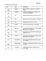
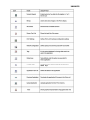
D. Description of Tool Icons............................................................................................233
E. List of Supported Devices.........................................................................................236
16. Frequently Asked Questions ..................................................................... 237
Index ......................................................................................................................... 239
Page vii
UMAN/OIS
Page viii
UMAN/OIS
0. General Safety Instructions and Information
Warning Labels Within Manual
Equipment Warning Labels
Preparation
Installation Precautions
Connection, Protection & Setup
System Integration Precautions
3rd Party Safety Certifications
Page 1
UMAN/OIS
0.1 Warning Labels Within Manual
DO NOT attempt to install, operate, maintain, or dispose of this equipment
until you have read and understood all of the product warnings and user
directions that are contained in this instruction manual.
Listed below are the signal words that are used throughout this manual
followed by their descriptions and associated symbols. When the words
DANGER, WARNING, and CAUTION are used in the manual, they will be
followed by important safety information that must be carefully adhered to.
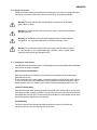
DANGER — The danger symbol is an exclamation mark enclosed in a triangle
that precedes the word DANGER. The danger symbol is used to indicate an
imminently hazardous situation that will result in serious injury, possible
severe property and equipment damage, or death if the instructions are not
followed.
DANGER
WARNING — The warning symbol is an exclamation mark enclosed in a
triangle that precedes the word WARNING. The warning symbol is used to
indicate a potentially hazardous situation that can result in serious injury, or
possibly severe property and equipment damage, or death, if the instructions
are not followed.
WARNING
CAUTION — The caution symbol is an exclamation mark enclosed in a
triangle that precedes the word CAUTION. The caution symbol is used to
indicate situations that can result in minor or moderate operator injury, or
equipment damage if the instructions are not followed.
CAUTION
Page 2
UMAN/OIS
To identify special hazards, other symbols may appear in conjunction with the
DANGER, WARNING, and CAUTION symbols. These warnings describe
areas that require special care and/or strict adherence to the procedures to
prevent serious injury and possible death.
Electrical Hazard — The electrical hazard symbol is a lightning bolt enclosed
in a triangle. The electrical hazard symbol is used to indicate high voltage
locations and conditions that may cause serious injury or death if the proper
precautions are not observed.
ELECTRICAL
HAZARD
Explosion Hazard — The explosion hazard symbol is an explosion image
enclosed in a triangle. The explosion hazard symbol is used to indicate
locations and conditions where molten exploding parts may cause serious
injury or death if the proper precautions are not observed.
EXPLOSION
HAZARD
Page 3
UMAN/OIS
0.2 Equipment Warning Labels.
DO NOT attempt to install, operate, maintain, or dispose of this equipment
until you have read and understood all of the product warnings and user
directions that are contained in this instruction manual.
Shown below are examples of warning labels that may be found attached to
the equipment. DO NOT remove or cover any of the labels. If the labels are
damaged or if additional labels are required, contact your Toshiba
representative for additional labels.
The following are examples of the warning labels that may be found on the
equipment and are there to provide useful information or to indicate an
imminently hazardous situation that may result in serious injury, severe
property and equipment damage, or death if the instructions are not followed.
Examples of labels that may be found on the equipment.
Page 4
UMAN/OIS
0.3 Preparation
Qualified Person
A Qualified Person is one that has the skills and knowledge relating to the
construction, installation, operation, and maintenance of the electrical
equipment and has received safety training on the hazards involved (Refer to
the latest edition of NFPA 70E for additional safety requirements).
Qualified Personnel shall:
•
Have carefully read the entire operation manual.
•
Be trained and authorized to safely energize, de-energize, ground, lockout
and tag circuits and equipment, and clear faults in accordance with
established safety practices.
•
Be trained in the proper care and use of protective equipment such as
safety shoes, rubber gloves, hard hats, safety glasses, face shields, flash
clothing, etc., in accordance with established safety practices.
•
Be trained in rendering first aid.
For further information on workplace safety visit www.osha.gov.
Equipment Inspection
•
Upon receipt of the equipment inspect the packaging and equipment for
shipping damage.
•
Carefully unpack the equipment and check for parts that were damaged
from shipping, missing parts, or concealed damage. If any discrepancies
are discovered, it should be noted with the carrier prior to accepting the
shipment, if possible. File a claim with the carrier if necessary and
immediately notify your Toshiba representative.
•
DO NOT install or energize equipment that has been damaged. Damaged
equipment may fail during operation resulting in further equipment damage
or personal injury.
•
Check to see that the model number specified on the nameplate conforms
to the order specifications.
•
Modification of this equipment is dangerous and must not be performed
except by factory trained representatives. When modifications are required
contact your Toshiba representative.
•
Inspections may be required before and after moving installed equipment.
•
Keep the equipment in an upright position as indicated on the shipping
carton.
•
Contact your Toshiba representative for assistance if required.
Page 5
UMAN/OIS
Handling and Storage
•
Use proper lifting techniques when moving the OIS; including properly
sizing up the load, and getting assistance if required.
•
Store in a well-ventilated covered location and preferably in the original
carton if the equipment will not be used upon receipt.
•
Store in a cool, clean, and dry location. Avoid storage locations with
extreme temperatures, rapid temperature changes, high humidity, moisture,
dust, corrosive gases, or metal particles.
•
Do not store the unit in places that are exposed to outside weather
conditions (i.e., wind, rain, snow, etc.).
•
Store in an upright position as indicated on the shipping carton.
•
Include any other product-specific requirements.
Disposal
Never dispose of electrical components via incineration. Contact your state
environmental agency for details on disposal of electrical components and
packaging in your area.
0.4 Installation Precautions
Location and Ambient Requirements
•
Adequate personnel working space and adequate illumination must be
provided for adjustment, inspection, and maintenance of the equipment
(refer to NEC Article 110-34).
•
Avoid installation in areas where vibration, heat, humidity, dust, fibers,
steel particles, explosive/corrosive mists or gases, or sources of electrical
noise are present.
•
The installation location shall not be exposed to direct sunlight.
•
Allow proper clearance spaces for installation. Do not obstruct the
ventilation openings. Refer to the recommended minimum installation
dimensions as shown on the enclosure outline drawings.
•
The ambient operating temperature shall be between 0° and 50° C (32°
and 122° F).
Mounting Requirements
• Only Qualified Personnel should install this equipment.
• Install the unit in a secure upright position in a well-ventilated area.
• A noncombustible insulating floor or mat should be provided in the area
immediately surrounding the electrical system at the place where
maintenance operations are to be performed.
Page 6
UMAN/OIS
• As a minimum, the installation of the equipment should conform to the
NEC Article 110 Requirements For Electrical Installations, OSHA, as well
as any other applicable national, regional, or industry codes and standards.
• Installation practices should conform to the latest revision of NFPA 70E
Electrical Safety Requirements for Employee Workplaces.
Conductor Routing and Grounding
•
Use separate metal conduits for routing the input power, and control
circuits.
•
A separate ground cable should be run inside the conduit with the input
power, and control circuits.
•
DO NOT connect control terminal strip return marked CC to earth ground.
•
Always ground the unit to prevent electrical shock and to help reduce
electrical noise.
The Metal Of Conduit Is Not An Acceptable
Ground.
Page 7
UMAN/OIS
0.5 Connection, Protection & Setup
Personnel Protection
•
Installation, operation, and maintenance shall be performed by Qualified
Personnel Only.
•
A thorough understanding of the OIS will be required before the installation,
operation, or maintenance of the OIS.
•
Rotating machinery and live conductors can be hazardous and shall not
come into contact with humans. Personnel should be protected from all
rotating machinery and electrical hazards at all times. Depending on its
program, the OIS can initiate the start and stop of rotating machinery.
•
Insulators, machine guards, and electrical safeguards may fail or be
defeated by the purposeful or inadvertent actions of workers. Insulators,
machine guards, and electrical safeguards are to be inspected (and tested
where possible) at installation and periodically after installation for potential
hazardous conditions.
•
Do not allow personnel near rotating machinery. Warning signs to this
effect shall be posted at or near the machinery.
•
Do not allow personnel near electrical conductors. Human contact with
electrical conductors can be fatal. Warning signs to this effect shall be
posted at or near the hazard.
•
Personal protection equipment shall be provided and used to protect
employees from any hazards inherent to system operation or maintenance.
System Setup Requirements
•
When using the OIS as an integral part of a larger system, it is the
responsibility of the OIS installer or maintenance personnel to ensure that
there is a fail-safe in place (i.e., an arrangement designed to switch the
system to a safe condition if there is a fault or failure).
•
System safety features should be employed and designed into the
integrated system in a manner such that system operation, even in the
event of system failure, will not cause harm or result in personnel injury or
system damage (i.e., E-Off, Auto-Restart settings, System Interlocks, etc.).
•
The programming setup and system configuration of the OIS may allow it
to start a motor unexpectedly. A familiarity with Auto-restart settings is a
requirement to use this product.
•
Improperly designed or improperly installed system interlocks may render
the motor unable to start or stop on command.
Page 8
UMAN/OIS
•
The failure of external or ancillary components may cause intermittent
system operation, i.e., the system may start a motor without warning or
may not stop on command.
•
There may be thermal or physical properties, or ancillary devices
integrated into the overall system that may allow the OIS to start a motor
without warning. Signs at the equipment installation must be posted to this
effect.
•
The operating controls and system status indicators should be clearly
readable and positioned where the operator can see them without
obstruction.
•
Additional warnings and notifications shall be posted at the equipment
installation location as deemed required by Qualified Personnel.
Page 9
UMAN/OIS
0.6 System Integration Precautions
The following precautions are provided as general guidelines for using an OIS
in an industrial or process control system.
•
The Toshiba OIS is a general-purpose product. It is a system component
and is used in conjunction with other items of industrial equipment such as
PLCs, Loop Controllers, Adjustable Speed Drives, etc.
•
A detailed system analysis and job safety analysis should be
performed by the systems designer or systems integrator before
including the OIS in any new or existing system. Contact Toshiba for
options availability and for application-specific system integration
information if required.
•
The OIS may be used to control an adjustable speed drive connected to
high voltage sources and rotating machinery that is inherently dangerous if
not operated safely. Interlock all energy sources, hazardous locations,
and guards in order to restrict the exposure of personnel to hazards. The
adjustable speed drive may start the motor without warning. Signs at the
equipment installation must be posted to this effect. A familiarity with Autorestart settings is a requirement when controlling adjustable speed drives.
Failure of external or ancillary components may cause intermittent system
operation, i.e., the system may start the motor without warning or may not
stop on command. Improperly designed or improperly installed
system interlocks and permissives may render a motor unable to
start or stop on command
•
Control through serial communications can fail or can also override local
controls, which can create an unsafe condition. System safety features
should be employed and designed into the integrated system in a manner
such that system operation, even in the event of system failure, will not
cause harm or result in personnel injury or system damage. Use of the
built-in system protective features and interlocks of the equipment being
controlled is highly recommended (i.e., emergency-off, overload protection,
etc.)
•
Never use the OIS units to perform emergency stops. Separate
switches outside the OIS, the PLC, and the ASD should be used for
emergency stops.
•
Changes or modifications to the OIS program should not be made without
the approval of the system designer or systems integrator. Minor changes
or modifications could cause the defeat of safety interlocks and
permissives. Any changes or modifications should be noted and included
with the system documentation.
Page 10
UMAN/OIS
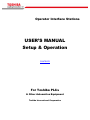
0.7 3rd Party Safety Certifications.
CE Marking
Page 11
UMAN/OIS
1. Introduction
Purpose of Manual
OIS Basics
Hardware Configuration
OIS Overview
What is OIS
OIS Specifications
Page 12
UMAN/OIS
1.1 Purpose of this Manual
Thank you for purchasing OIS EV3 Series Products from Toshiba International
Corp.. OIS Series Products are versatile operator interfaces with Microsoft
Windows based configuration Software.
This Manual explains the operation of the OIS Series and how to implement
available features using the OIS32 Soft-ware. This manual will help you to install,
configure and operate your OIS product.
1.1.1
OIS Basics
Operator Interface Terminals (OISs) provide much more versatility than traditional
mechanical control panels. An OIS allows a plant floor operator to monitor current
conditions of a control system and, if necessary, to initiate a change in the operation of the system. OISs connect to programmable logic controllers (PLCs) typically
through the serial communications port. The OIS can be programmed to monitor
and/or change current values stored in the data memory of the PLC.
OISs can have either text or graphics based displays. A text based OIS can
display printable text characters but can not print graphics.
Some OISs use touch screen displays while others use a PCB based keypad. PCB
based keypads are best used in applications in which the keypad is likely to
become dirty. A touch screen OIS provides much more flexibility than typical PCB
based keypad displays. Keys can be created in a touch screen OIS that can be
made visible only when needed. The OIS Series OISs are available in both text
display based OIS and graphics display based OISs.
What is a Project?
A project is an user created application in OIS32 Software. A project contains
information such as OIS model, Network Configuration, Screen information, Task
information etc.
What is a Screen?
A screen is a visual representation of objects placed on the OIS screen. Any
partially sized window is usually referred to as a popup screen or window. The user
can create his customized screen according to his requirements. Popup windows
can also appear on the OIS display by pressing buttons on the touch screen . The
maximum number of screens in an application is only limited by the application
memory size. A more in depth discussion on screens is covered in chapter 4.
Page 13
UMAN/OIS
What is an Object?
An object placed on OIS screen can perform actions such as displaying text
messages, writing a value to a PLC register, or displaying an alarm. An object can
be classified as a text or graphical object.
A text object is used to display the text on the OIS and can also used to perform
some action. For example, a data entry object tells the OIS to continuously monitor
a PLC register and allows the user to change the value in the register. Some
objects can display graphics whose shape depends on the value of a register.
These objects may also change the value of a PLC tag. An example is a Bit Button
Object that creates a graphic object on the OIS. When pressed, it activates a bit in
the PLC.
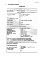
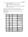
1.1.2 Hardware Requirements
The following basic PC hardware configuration is needed to configure and operate your
OIS32 Software.
DEVICE
MINIMUM REQUIREMENT
IBM Compatible PC with
Pentium Processor
266MHz Pentium® II or higher Pentium
compatible CPU
Operating System
Windows® 2000 and above
System RAM
At least 64 megabytes (MB) of RAM, more
memory generally improves responsiveness
Hard Disk
150 MB Free Memory Space
VGA Monitor Color
Setting Resolution
800 x 600 with 24 bit True Color
Serial Port
Serial Port for Downloading
Mouse
Microsoft® Mouse or compatible pointing device
Keyboard
Required
These are the minimum system requirements for a computer running the OISetup32 software.
Page 14
UMAN/OIS
1.2 OIS Overview
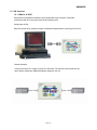
1.2.1 What is an OIS?
OIS provide Human-Machine Interface to the Programmable Logic Controller. These OISs
communicate with PLCs using their serial communications ports.
Configuration of OIS:
Each OIS unit has to be configured using the OISetup32 Software before connecting it to the PLC.
Normal Operation:
Connect OIS unit to PLC using the correct PLC-OIS cable. The OIS can communicate with any
device without making any additional hardware settings on the unit.
Page 15
UMAN/OIS
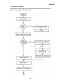
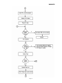
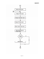
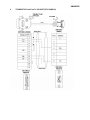
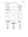
1.2.2 How the OIS Works
The OIS follows a specific sequence for performing the tasks defined by the user in the
application. The sequence is as shown below:
Page 16
UMAN/OIS
Page 17
UMAN/OIS
Page 18
UMAN/OIS
Page 19
UMAN/OIS
1.2.3 Specifications of OIS Series
OIS series models are Human Machine Interfaces with optional Input/Output capability. OISs with
Input/Output capability are termed as HIO. OIS series OISs can be powered either from the PLC or from an
external power supply. PLC powered units are referred to as IOP, whereas externally powered units are
referred to as OIS. HIO units can not be powered from a PLC. HIO models can be externally from a DC or
AC source.
OIS models need +24VDC power from an external supply. HIO can either be external +24VDC powered or
85-265, 50/ 60Hz VAC powered.
Models included in the OIS Series are as follows:
OIS40/40R
OIS50
OIS55
OIS60
OIS120
The functionality of OIS and HIO products is exactly the same. The only difference between a OIS
product and an HIO product is the addition of real I/O to the HIO unit. A OIS application can be
downloaded to a corresponding HIO model. All of the OIS EV3 series models have ladder functionality
built in.
All OIS EV3 series models have two serial communication ports. They can communicate with two
different PLCs simultaneously.
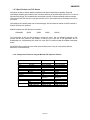
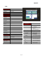
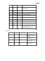
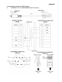
1.2.4 Comparison Between Keypad Based OIS Operator Panels
Model
Display
Keys
LEDs
Memory
OIS40
Function
Numeric
Total
Application
Ladder
Data Logging
Trending
Alarms
Recipes
Password
Dimensions
Yes
Yes
101 HX183WX37D
163W X 77H mm
128 X 64 Pixels
8 User Definable
12
8
512 KB
120 KB
62 KB
N. A.
N. A.
Real Time
Historical
Yes
Yes
Yes
101 HX183WX37D
163W X 77H mm
Page 20
OIS40R
128 X 64 Pixels
8 User Definable
12
8
512 KB
120 KB
62 KB
N. A.
N. A.
Real Time
Historical
Yes
Yes
Yes
101 HX183WX37D
163W X 77H mm
UMAN/OIS
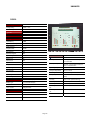
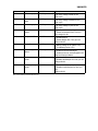
1.2.5 Comparison Between Touchscreen Based OIS Panels
Model
Display
Type
OIS50
OIS55
4.1” Yellow Backlit 3.5" TFT Graphical
Color Display,
LCD
Graphical Display 6 Function Keys
Resolution 192 X 62 Pixels
320 X 240 Pixels
Brightness Standard Through
Control
Pot
Touchscree
Analog Resistive Analog Resistive
n
5.7” STN CCFL
QVGA
Graphical Color
Di l
320 X 240 Pixels
OIS120
12.1: TFT CCFL
Graphical Color
800 X 600 Pixels
Standard Through Standard Thru.
Pot
Pot
Analog Resistive
Analog Resistiv
3 MB
4 MB
32 MB
Applicati
120 KB
on
2.56 MB
3 MB Maximum*
25 MB Maximum
Ladder
512 KB
128 KB
2 MB
N.A.
2 MB*
2 MB*
N.A.
Yes
Yes
Total
Memory
OIS60
512 KB
62 KB
Data
N.A.
Logging
Data
N.A.
Logging
Trending
N.A.
Real Time
Real Time +
Historical
Real Time +
Historical
Alarms
Real Time +
Historical
Real Time +
Historical
Real Time +
Historical
Real Time +
Historical
Recipes
Yes
Yes
Yes
Yes
ScreenSave
N.A.
r
Yes
Yes
Yes
Yes
Yes
Yes
Yes
Yes
Yes
91Hx136W x29D
139HX197WX58.5D 246HX312WX47
127W x 77H
184W X 126H mm
Screen Yes
P
W Applicati
Yes
on
External
Dimensi 77HX140WX32D
Di ons
m
Panel
132W X 69H mm
Cutout
*
D
295W X 227H mm
Note: Total memory can be adjusted between application memory, ladder memory, and
data logging memory.
Page 21
UMAN/OIS
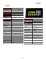
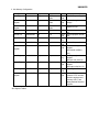
OIS40/40R
Power Supply
OIS40, from PLC
Voltage Rating
OIS40R, 24VDC
24 VDC + 10%
Power Rating
3W Maximum
Approvals
CE Certified and UL Listed 58DN
Bezel
IP65 Rated Keypad
Keypad
PCB based Keypad With Tactile
Feedback Keys, Insertable Legend
Number Of Keys
8 User Definable keys and 12 Numeric
Keys
Memory
Communication
Number of Ports
2
Type
RS232 / RS485 / RS422 / CMOS
Total Memory
512KB
Application Memory
120KB
Ladder Memory
62KB
External Dimension
Data Register
1000
Battery
Retentive Register
1400
System Register
64
System Coil
100
Internal Coil
5000
Input Coil
100
Output Coil
100
Internal Register
313
Input Register
7
Output Register
7
Timer Register
128
Counter Register
178
Display
LCD Text Display
Display Type
4 lines of 16 characters Backlit LCD
LEDs
8 LEDs
Miscellaneous
Battery Backup
101 H X 183 W X 37 D mm
Coin Type, 3V Lithium Battery
614-CR1225FH
Minimum 5 years battery backup for
RTC and System data
Operating Temperature
0 0C to 50 0C
Storage Temperature
-25 0C to 80 0C
Mounting Method
Panel Mounting
Clock(RTC)
Real Time Clock Function(Date &
Time)
Humidity
10% To 90% (Noncondensing)
Immunity to ESD
Level 3 as per IEC1000-4-2
Immunity to Transients
Level 3 as per IEC1000-4-4
Immunity to Radiated
RF
Level 3 as per IEC1000-4-3
Immunity to Conducted
RF
Level 3 as per IEC1000-4-6
Emission
EN55011 CISPRA
Page 22
UMAN/OIS
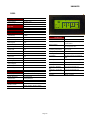
OIS50
Power Supply
24VDC
Voltage Rating
24 VDC + 10%
Power Rating
3.5W Maximum
Approvals
CE /CSA Certified & UL Listed 58DN
Bezel
IP65 Rated
Memory
Total Memory
512KB
Application Memory
120KB
Ladder Memory
62KB
Data Register
1000
Retentive Register
1400
System Register
64
System Coil
Miscellaneous
External Dimension
77 H X 140 W X 32 D mm
Battery
Battery Backup
Coin Type, 3V Lithium Battery
614-CR1225FH
Minimum 5 years battery backup for
RTC and System data.
100
Operating Temperature
0 0C to 50 0C
Internal Coil
5000
Storage Temperature
-25 0C to 80 0C
Input Coil
100
Mounting Method
Panel Mounting
Output Coil
100
Clock(RTC)
Internal Register
313
Real Time Clock Function(Date &
Time)
Input Register
7
Humidity
10% To 90% (Noncondensing)
Output Register
7
Immunity to ESD
Level 3 as per IEC1000-4-2
Timer Register
128
Immunity to Transients
Level 3 as per IEC1000-4-4
Counter Register
178
Level 3 as per IEC1000-4-3
Display
LCD Graphic Display
Immunity to Radiated
RF
Immunity to Conducted
RF
Display Type
4.1” Yellow Backlit LCD Display
Emission
EN55011 CISPRA
Display Resolution
192 X 64 Pixels
Touch Screen
Analog Resistive
Communication
Number of Ports
Type
2
RS232 / RS485 / RS422 / CMOS
Page 23
Level 3 as per IEC1000-4-6
UMAN/OIS
OIS55
Power Supply
24VDC
Voltage Rating
24 VDC + 10%
Power Rating
3.5W Maximum
Approvals
CE /CSA Certified & UL Listed 58DN
Bezel
IP65 Rated
Memory
Total Memory
3 MB
Application Memory
2.56 MB
Ladder Memory
512 KB
Data Register
1000
Retentive Register
1400
System Register
64
System Coil
100
Internal Coil
5000
Input Coil
100
Output Coil
100
Internal Register
313
Input Register
7
Output Register
7
Timer Register
128
Counter Register
178
Display
Graphical Color Display (256 colors)
Display Type
3.5” TFT
Display Resolution
320 x 240 Pixels
Touch Screen
Analog Resistive
Miscellaneous
Communication
Number of Ports
3
Type
RS232 / RS485 / RS422 / CMOS
Page 24
External Dimension
90.5 H x 135.5 W x 29 D mm
Battery
Battery Backup
Coin Type, 3V Lithium Battery
614-CR1225FH
Minimum 5 years battery backup for
RTC and System data.
Operating Temperature
0 0C to 50 0C
Storage Temperature
-25 0C to 80 0C
Mounting Method
Panel Mounting
Clock(RTC)
Real Time Clock Function(Date &
Time)
Humidity
10% To 90% (Noncondensing)
Immunity to ESD
Level 3 as per IEC1000-4-2
Immunity to Transients
Level 3 as per IEC1000-4-4
Immunity to Radiated
RF
Immunity to Conducted
RF
Level 3 as per IEC1000-4-3
Emission
EN55011 CISPRA
Level 3 as per IEC1000-4-6
UMAN/OIS
OIS60
Power Supply
24VDC
Voltage Rating
24 VDC + 10%
Power Rating
10W Maximum
Approvals
CE /CSA Certified & UL Listed 58DN
Bezel
IP65 Rated
Memory
Total Memory
4MB
Application Memory
3 MB Maximum
Ladder Memory
512KB
Data Register
1000
Retentive Register
1400
System Register
64
System Coil
100
Internal Coil
5000
Input Coil
100
Output Coil
100
Internal Register
313
Input Register
7
Output Register
7
Timer Register
128
Counter Register
178
Display
Graphical Color Display
Display Type
5.7” STN CCFL QVGA Display
Display Resolution
320 X 240 Pixels
Touch Screen
Analog Resistive
Miscellaneous
External Dimension
Battery
1
Operating Temperature
Coin Type, 3V Lithium Battery
614-CR1225FH
Minimum 5 years battery
backup for
RTC and System data.
0 0C to 50 0C
Storage Temperature
-25 0C to 80 0C
Mounting Method
Panel Mounting
Clock(RTC)
Humidity
Real Time Clock
Function(Date &
Ti )
10% To 90% (Noncondensing)
Immunity to ESD
Level 3 as per IEC1000-4-2
Battery Backup
Immunity to Transients
Level 3 as per IEC1000-4-4
Immunity to Radiated
RF
Level 3 as per IEC1000-4-3
3
RS232 / RS485 / RS422 / CMOS
Immunity to Conducted
RF
Level 3 as per IEC1000-4-6
USB
Emission
EN55011 CISPRA
Communication
Number of Ports
Type 2
139 H X 197 W X 58.5 D mm
Page 25
UMAN/OIS
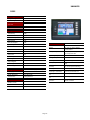
OIS120
Power Supply
24VDC
Voltage Rating
24 VDC + 10%
Power Rating
20W Maximum
Approvals
CE Certified and UL Listed 58DN
Bezel
IP65 Rated
Memory
Total Memory
32 MB
Application Memory
25 MB
Ladder Memory
2 MB
Compact Flash
256 MB
Data Register
1000
Retentive Register
1400
System Register
64
System Coil
100
Internal Coil
5000
Input Coil
100
Output Coil
100
Internal Register
313
Operating Temperature
0 0C to 50 0C
Input Register
7
Storage Temperature
-25 0C to 80 0C
Output Register
7
Mounting Method
Panel Mounting
Timer Register
128
Clock(RTC)
Counter Register
178
-
Real Time Clock Function(Date &
Time)
Display
Graphical Color Display
- Humidity
10% To 90% (Noncondensing)
- Immunity to ESD
Level 3 as per IEC1000-4-2
Display Type
12.1” TFT CCFL Display
- Immunity to Transients
Level 3 as per IEC1000-4-4
Display Resolution
800 X 600 Pixels
Analog Resistive
- Immunity to Radiated
RF
Level 3 as per IEC1000-4-3
Touch Screen
Immunity to Conducted
- RF
Level 3 as per IEC1000-4-6
- Emission
EN55011 CISPRA
- Miscellaneous
- External Dimension
- Battery
_ Battery Backup
Communication
Number of Ports
3
Type
2
RS232/RS485/RS422/CMOS
1
Ethernet
Page 26
246 H X 312 W X 47 D mm
Coin Type, 3V Lithium Battery
614-CR1225FH
Minimum 5 years battery backup for
RTC and System data.
UMAN/OIS
Page 27
UMAN/OIS
2. Hardware
Unpacking the Unit
Managing Electrostatic Discharge
CE Compliance
Environmental Rating
Safety Precautions
Installation Instructions
Wiring Diagrams
Communications Ports
UMAN/OIS
2.1 Unpacking The Unit
Carefully unpack the OIS. Please read all the instructions and cautions that appear on the shipping
container.
Check that the container includes the mounting clamps, mounting screws, mounting inserts, gasket,
and a silica gel bag. The silica gel bag is enclosed to absorb the moisture in the packing. TIC will
not accept responsibility for shortages against the packing list unless notified within 30 days. The
unit and its accessories were inspected and tested by TIC before shipment. All equipment should
be in good working order. Examine the product carefully and notify the carrier immediately if any
shipping damage is evident. You are responsible for claim negotiations with the carrier. Save the
shipping container and packing material in case the equipment needs to be stored, returned to
TIC , or transported for any reason.
2.2 Managing Electrostatic Discharge
It is best NOT to remove the rear enclosure of the OIS. When the rear part of the enclosure is
removed, the circuitry inside is exposed to possible damage by electrostatic discharge during
handling. Minimize the possibility of electrostatic discharge by:
Discharging personal static by grounding yourself prior to handling the OIS.
Handling the OIS at a static-free grounded workstation.
Connecting the frame ground ( ) connector of the OIS to a clean earth ground.
Placing the OIS in an antistatic bag during transport.
2.3 CE Compliance
TIC products have been tested to confirm to European CE requirements per Council Directive. The
European Union created these requirements to ensure conformity among products traded in those
countries. Specifically, TIC products meet or exceed the noise emission and immunity
requirements as set in EN5501 1 (Emission) and IEC1000-4 (Immunity) standards. These products
are designed to withstand electrical noise in harsh industrial environment. They also confirm to
requirements that limit electrical emission. However this does not guarantee the products will be
totally immune from possible malfunction in cases where severe electrical noise occurs. Therefore,
we strongly recommend that you follow the guidelines outlined for proper wiring and grounding to
ensure the proper operation of the TIC products.
2.4 Environmental Rating
TIC Products are rated for IP 65 as per IEC Standards. This means that when OIS is properly
mounted on the enclosure, the front enclosure will provide a degree of protection to the inside panel
from the dust and low pressure jets of water from all the directions i.e. protection against ingress of
water. The OIS must be installed according to the instructions given.
2.5 Environmental Consideration
0
TIC products are designed to operate at temperature range from 0-50 C. It is intended primarily
for indoor installations and may not be suitable for certain outdoor applications. Avoid installing the
TIC products in environments with severe mechanical vibration or shocks. Do not install the OIS in
enclosures with rapid temperature variations or high humidity. Either will cause condensation of
water inside the device and eventual damage to the OIS.
UMAN/OIS
2.6 Safety Precaution
Please observe the following precautions when installing the unit. Failure to comply with these
restrictions could result in loss of life, serious personal injury, or equipment damage.
Warning: Do not operate the OIS in areas subject to explosion due to flammable
gases, vapors, or dusts.
Warning: Do not connect the OIS to an AC power source. You will cause permanent
damage to the OIS.
Warning: Do not attempt to use a DC power supply that does not meet OIS power
requirements. You may cause malfunction or permanent damage to OIS.
Warning: Do not power the OIS with a DC power supply used for inductive loads or
for input circuitry to the programmable logic controller. Severe voltage spikes
caused by these devices may damage the OIS.
2.7 Installation Instructions
The OIS should be mounted on a panel. A sealing gasket and mounting clamps are provided with
each OIS unit for proper installation.
Environmental Considerations:
Make sure that the unit is installed correctly and that the operating limits are followed (see
Specifications for OIS).
Do not operate the OIS in areas subject to explosion hazards due to flammable gases, vapors
or dusts. A OIS should not be installed where fast temperature variations are present. Highly
humid areas are also to be avoided. High humidity causes condensation of water in the unit.
Location Considerations:
Care should be taken when locating equipment behind the OIS to ensure that AC power wiring,
PLC output modules, contactors, starters, relays and any other source of electrical interference
are located away from the OIS . Particular care should be taken to locate variable speed drives
and switching power supplies away from the OIS.
Panel Mounting
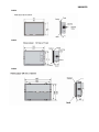
This section presents the dimensional sketches and panel cutouts for OIS products.
(All dimensions are in mm and drawings are not to scale.)
UMAN/OIS
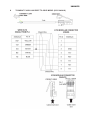
2.7.1 Panel Cutouts for OIS Models
OIS40/40R
UMAN/OIS
OIS50
OIS55
OIS60
UMAN/OIS
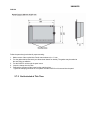
OIS120
Follow the procedure given below for proper mounting:
1. Make a cutout of the required size. Panel cutout tolerance is + 0.1 mm.
2. Put the gasket behind the bezel (see dimensional sketch for details). The gasket may be sealed to
the case using an adhesive.
3. Put the OIS EV3 unit through the panel cutout.
4. Insert the clamps into the case.
5. Pullback the clamps until they seat into the retaining slots.
Tighten the clamping screws in an even pattern until the OIS EV3 unit is secured into the panel.
2.7.2 Not Included at This Time.
UMAN/OIS
2.8 Wiring Diagrams
If wiring is to be exposed to lightening or surges, use appropriate surge suppression devices. Keep AC,
high energy and rapidly switching DC wiring separate from signal wires.
Connecting high voltages or AC power mains to the DC input will make unit unusable and may create an
electrical shock hazard to personnel. Such a failure or shock could result in serious personal injury, loss of life
and/or equipment damage. DC voltage sources should provide proper isolation from main AC power and
similar hazards.
Pin description of the power connector for all Prizm models is as follows:
24V
dc+
Vdc-
Gnd
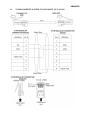
2.9 Communication Ports
OIS communication ports support four types of serial communication.
They have two Multisignal communication Ports. Multi-Signal means that each port has RS232, RS422,
RS485 and CMOS signal levels.
An OIS can simultaneously communicate on both serial ports. The OIS can be programmed from a PC on
either port. Both ports can also be used with a serial printer.
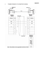
Different cables are required to connect the OIS to a specific PLC. Cable details for any particular device are
given in the Operation Manual for that device. The pin description of the communication ports for OIS model
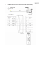
is as given below:
For OIS55 model, the pin description of communication ports is as given below:
UMAN/OIS
3. Before You Begin
Connecting the OIS to a Computer
Starting the OISetup32 Software
Setting Network Configuration
UMAN/OIS
3.1 Connecting the OIS to a Computer
Before you start your first project, the OIS should be connected to the computer so that the project can be
downloaded after creating it. You should also connect the PLC that you are using to the OIS so that you
can test the operation of the OIS after you have finished creating the sample project:
To connect your OIS to the Computer
Connect a +24VDC power supply to the OIS.
Connect the programming cable to the computer and OIS.
• Connect IBM cable to the communication port of OIS.
• Download Firmware i.e. driver for the PLC. The OIS unit cannot communicate with PLC till the
required driver is downloaded.
3. Apply power to the OIS.
4.
To connect your PLC to OIS
A OIS can communicate with any PLC without any change in the OIS hardware. To communicate with a
PLC, the OIS unit needs:
1. Proper Communication Driver for the PLC
Each PLC has a defined protocol for communicating with any device. The communication driver is
down loaded into the OIS unit along with the firmware. The communications driver varies from PLC to
PLC. This driver enables the unit to talk to a specific PLC.
2. OIS - PLC communication cable A proper OIS - PLC cable is required for error free communication
with any PLC.
1.
2.
UMAN/OIS
3.2 Starting OISetup32 Software
3.2.1 Installing OISetup32 Software
System requirements for installing OISetup32 on your PC:
Windows Version
Processor
Disk Space
Serial Mouse
RAM
Display Resolution
Serial Port
Microsoft Windows® 2000 or higher
266 MHz Pentium® I I or higher Pentiumcompatible CPU
150 MB free memory space
Microsoft® mouse or compatible pointing
device
At least 64 megabytes (MB) of RAM; more
memory generally improves responsiveness
Display resolution
800 X 600 with 24 bit true color
One Serial Port for Downloading Required
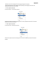
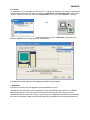
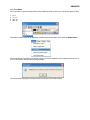
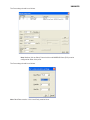
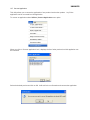
To install OISetup32 Software:
1. Open Microsoft Windows.
2. Select Run and Pop up window appears. Type the path for installing the Setup. This will install
OISetup32 Setup Software.
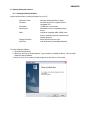
3. When you click on OK, Welcome window appears on the screen. Click on Next.
UMAN/OIS
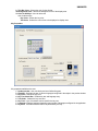
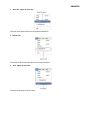
4. Enter your name and company name.
5. Select the destination folder where Setup will install the files.
UMAN/OIS
7. Installation starts. A dialog box indicating the status of progress of
installation will display. A screen is displayed to inform you when
installation is completed.
This procedure installs OISetup32 Software in Start Menu (in selected folder).
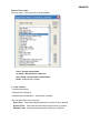
3.2.2 Steps for starting OISetup32 Software
1. In Windows click the Start button.
2. Select Programs.
3. Select OIS V3.12.
4. Select OISetup32 V3.12
5. Select New Application either from Tool station or from File Menu.
6. Select the model and product type that you would like to set by clicking on picture of the product in
the list.
7. Define the Unit Settings and Network Configuration.
8. Next step is to define Tag Database and then define the screens according to your application.
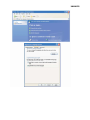
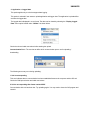
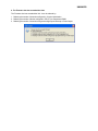
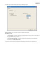
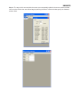
3.2.3 Uninstalling OISetup32 Software
1.
2.
3.
4.
In Windows click the Start button.
Select Programs.
Select OISetup32 V3.12.
Select Uninstall OISetup32 V3.12.
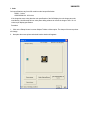
Following screen will display. The screen will ask you for the confirmation for uninstalling
OISetup32 V3.12.
UMAN/OIS
7. When you click on Yes, it will uninstall OISetup32 V3.12 from your computer.
If you want to install OISetup32 V3.12 again you have to follow the steps explained in section 3.2.1.
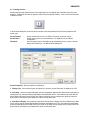
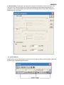
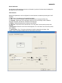
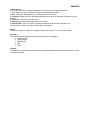
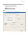
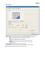
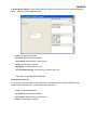
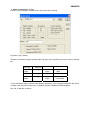
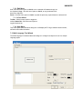
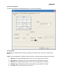
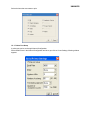
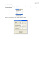
3.3 Setting Network Configuration
Unit can communicate with any PLC without any changes in the hardware. To communicate with
PLC unit needs proper communication driver. Each PLC has a defined protocol for communicating
with any device. PLC driver is downloaded into unit along with the firmware. This driver enables the
unit to talk to a specific PLC.
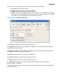
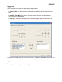
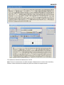
Using this configuration screen you can set the node address (0 to 255), node name for each port.
You can change default values generated by editing these two fields. Protocol selection box
displays list of all supported PLCs. By clicking this selection box you can see list of Model
Numbers in PLC Model selection Box. Select PLC Name from PLC selection box and PLC Model
name from PLC Model selection box.
PLC specific data button is activated only if selected PLC has Special PLC specific data to be set.
Unit can be configured in following ways:
1. For IBM Communication
2. For Serial Printing
3. For PLC Communication
Either of the ports can be configured for the ways mentioned above. Depending on the type of
communication, the user may be required to define certain parameters.
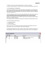
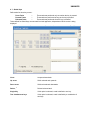
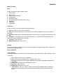
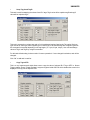
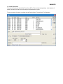
The following table displays the number of nodes connected on COM1, COM2 and COM3 with their
node addresses, node name, node type (unit/PLC) and total number of blocks used in application.
UMAN/OIS
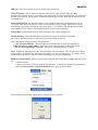
Note: The OIS default unit address is 0 for COM1, COM2. If the default address of a PLC
connected to COM1, COM2 is 0 then the OIS unit address must be changed to a nonzero
number.
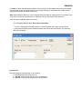
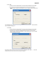
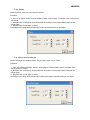
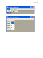
1. For IBM Communication
These are the default communication settings. If the user wants IBM Communication, no other
setting is required. In this case both communication ports can be used for download / upload
purpose.
UMAN/OIS
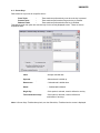
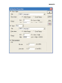
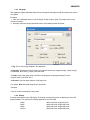
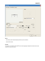
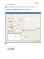
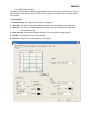
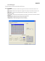
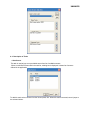
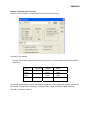
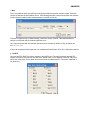
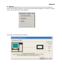
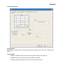
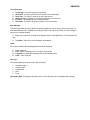
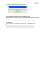
2. For Serial Printing
The user can use either of the ports for serial printing. This is done by selecting Protocol as “Serial
Printer”. In the above example, the user has configured COM1 for serial printing. However, when
this port is not being used for printing, it can be used for IBM communication.
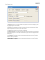
The user can change the serial printing parameters by selecting the “Comm Settings” option.
UMAN/OIS
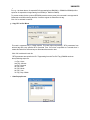
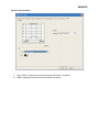
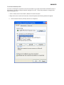
The following parameters can be modified for serial printing:
Baud Rate: supported baud rates are 4800, 9600, 19.2K,
38.4K, 57.6K and 115.2K. Parity: Parity can be None, Even
or Odd.
Number of bits: Number of bits can be 7 or 8.
Number of Columns: Number of columns can be minimum 1
to maximum 255. Terminating Character: Can be None, CR
(Carriage Return), LF (Line Feed) or CR+LF. Number of
characters to print: Can be from minimum 1 to maximum 256.
Click Ok to set printer setting.
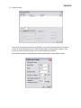
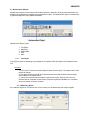
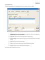
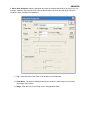
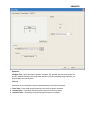
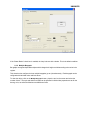
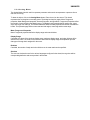
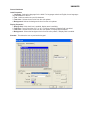
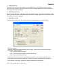
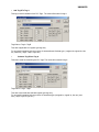
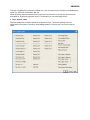
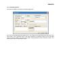
3. For PLC Communication
Protocol - User can select desired PLC from the list of available drivers. In the example shown
above, user has selected Omron Host Link at COM1.
Port SettingsUser can set PLC communication parameters like Baud Rate, Parity,
Data Bits and Stop Bits. Click Ok to set the parameters.
UMAN/OIS
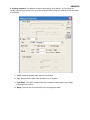
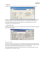
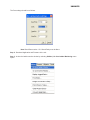
Model: Select the desired PLC model from the drop down list. In the example shown
above, the user selected the “K Type” model.
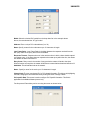
Address: Enter a unique PLC node address ( 0 to 32)
Name: Specify a name for the node name up to 15 characters in length.
Inter Frame Delay: Inter Frame Delay is the delay between the response received from the
last query and the next query that is to be transmitted.
Response Timeout: Response time out is the maximum time in which a slave should respond
to a master query. If the slave does not respond to the master query within the time, the master
will declare the slave has timed out.
Retry Count: Retry count is the number of retry queries the master will send to the slave.
When all retries are complete, the master will declare a communications break and will show !!!!
Add Node: This will add the node to the network.
Name: Specify a name for the node up to 15 characters in length.
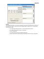
Change Node: The user can change PLC or PLC related information. This is done by highlighting
the node, changing the information and finally clicking the button ‘Change a Node’.
PLC specific Data: This screen is used to configure PLC Specific information. This field is
applicable for the Modbus Master protocol only.
For this protocol Frame delay can be set using the screen as shown below.
UMAN/OIS
4. Using OISetup32 Software
OISetup32 Menu Structure
Creating a New Application
Creating Screens
Data Entry Objects
Display OIS or PLC Data Object
Global and Power on Tasks
Global Keys
Screen Keys
UMAN/OIS
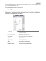
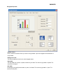
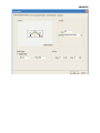
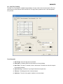
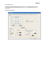
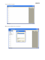
4.1 OIS Menu Structure
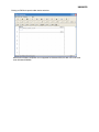
From Windows Task Bar, click the Start button, point to OISetup, and then click the OISetup program. The
following window will appear.
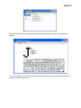
The program displays a splash screen at start-up. This dialog can be closed by pressing any key, mouse
click, or waiting 10 seconds for it to automatically go to the next screen (ie.Toolstation).
UMAN/OIS
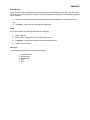
The menu bar operates like any standard Windows Menu bar. To open a particular menu, click it with the
mouse or use the key along with the ALT key. When no application is opened, the menu bar shown
above will be displayed.
UMAN/OIS
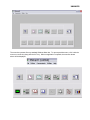
The Tool-Station consists of icons. When the mouse cursor rests over any icon, a tool-tip is displayed. Click
on the icon to select the particular menu.
Now we will study the different Menus in the Menu Bar.
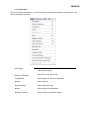
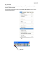
4.1.1 File Menu
The file menu handles file related functions including New Application, Close Application, Save Application,
Print and Exit OIS. Selecting the Information option allows the user to set or change OIS application
information such as application title, user name etc.
Unit Settings
-
Network Configuration
-
Shows the unit’s settings. Normally there is no need to
change these settings.
Defines PLC node, node I D etc.
Tag Database
-
Defines tags to be used in the application.
Screens
-
Defines screens.
Application Keys
-
Defines application keys.
Alarms
-
Defines alarms in the application.
Application Task-List
-
Defines Power-on and Global Tasklist.
UMAN/OIS
4.1.2 Define Menu
This menu defines the application. In the main window of the OISetu32 software, the bottom line of the
icons is dedicated to this menu.
Unit Settings
-
Network Configuration
-
Shows the unit’s settings. Normally there is no need to
change these settings.
Defines PLC node, node I D etc.
Tag Database
-
Defines tags to be used in the application.
Screens
-
Defines screens.
Application Keys
-
Defines application keys.
Alarms
-
Defines alarms in the application.
Application Task-List
-
Defines Power-on and Global Tasklist.
UMAN/OIS
4.1.3 Communicate Menu
The communicate menu has options for selection COM port, downloading/uploading OIS applications, etc.
Communication Port
-
Sets COM port for communicating with OIS.
Download
-
Downloads Application to OIS Unit.
Upload
-
Uploads Application from OIS Unit.
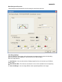
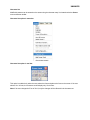
4.1.4 Utilities Menu
The utilities menu informs the user about the memory used for the application. This menu has other
options like Font Editor, image conversion, clear picture library and load default fonts.
OIS Memory status
-
Displays statistics of the memory used by the current
application.
Display logged data
-
Displays the logged data in the OIS memory.
Font Editor
-
User can edit the fonts by the Font Editor utility.
Image Conversion to bitmap
-
Clear Picture Library
-
Load Default Fonts
-
Converts images from any type of picture format to
bitmaps.
User can clear the picture library. Close the applications
before clearing Picture library.
Loads the default OIS fonts.
UMAN/OIS
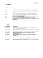
4.1.5 Help Menu
The Help Menu offers help, programming assistance, and information about the OISetup32 version.
Index
-
Lists all of the Help topics
About OIS Software
-
Displays the software version number and date.
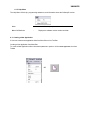
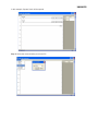
4.2 Creating a New Application
A User can create a new application either from Menu Bar or from Tool Bar.
Creating a New Application from Menu Bar:
To create a New Application either choose File | New menu option or click on New Application icon from
Toolbar.
OR
UMAN/OIS
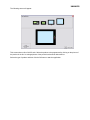
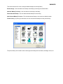
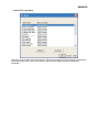
The following screen will appear:
This screen shows a list of all OIS units. Select the product to be programmed by clicking on the picture of
the product in the list. An enlarged picture of the product is also shown below the list.
Select the type of product and then click the OK button to start the application.
UMAN/OIS
Steps for creating a new application are as follows:
1) Start a new project using either File Menu or Tool section New command.
2) Define unit’s settings.
3) Define Network Configuration for selected unit and PLCs.
4) Define tags required for the application in the Tag Database.
5) Define the screens.
6) Define Power-on , Global and Screen tasks.
7) Save your application.
8) Download firmware to the unit.
9) Download your application into the unit.
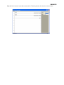
Tag Database
This is the central database for the tags that need to be used in the application. Once the tags are defined
(as register or coils) and their attributes selected, the tags can be used in the application on screens, tasks,
alarms etc. This screen helps you to define Tags associated with defined Nodes. A tag is a register, coil or
an individual bit of a register. Select the type of tag from the Tag Type field.
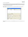
If the type of tag selected is a register then the number of bytes required can also be selected. For displaying
or editing a floating point data number, the number of bytes must be 4. The Tag Name field is user definable.
A tag is not added to the tag list unless a tag name is defined. Once these fields are defined, click on the
Add button. The Block field in the tag database defines the starting address of the tag block followed by the
block size.
For example : Tag M0214 is within a block ( M0214 : 1 ) whose starting address is M0214 and
block size is 1 This block size is optimized automatically depending on the address of PLC Tag.
Default block size is either 1 or 16. This setting varies from PLC to PLC.
The attributes of existing tag can be changed by highlighting the tag, making the changes, and clicking the
Change Tag button. An existing tag can be removed from tag list by clicking on Delete Tag button. Note that
removal of tags is possible only if they are not used on any screen.
UMAN/OIS
Add - Use this button to add a tag. Before clicking this button, the user has to define the following:
1. Node : Where the tag is located.
2. Register, coil or a bit within a register. Registers can be read only or
read/write. The address limits are shown and vary from PLC model to
model.
4. Tag name : Each tag needs to have a unique name. The name can be up to 40 characters in
length.
5. Byte(s) : If the selected tag is a register, the tag can be defined as a 1 byte ( either high or
low byte), a 2 byte, or a 4 byte tag.
Change – Select the tag. Change the information and then click on the Change button.
Delete - Select the tag and click on Delete button to delete the tag. Before deleting any tag, the user
must delete any references to the tag in screens and tasks. Otherwise it can not be deleted.
Default System Tags
Note: Please do not attempt to modify read only system tags in the ladder. This could affect the
functionality of the product.
1. System Registers
Register/Coil
Tag Name
Read / Write
Description
S0001
Language
Read / Write
S0002
Logger
Memory
Status
Read Only
S0003_14
Comm1 Status Read Only
S0003_15
Comm2 Status Read Only
S0003_00
Logger
memory
full status
Logger
memory
clear status
RTC fail
Read Only
Writing the value will
change languages
Shows the percentage
usage of status logger
memory. ( 0 to 100 )
0 = Communication Error
1 = Communicating with
PLC
0 = Communication Error
1 = Communicating with
PLC
1 = memory full
Invalid
max/min
Number of
Historical
S0003_01
S0003_02
S0003_03
S0004
S0005
Read Only
1 = memory clear routine
being executed
Read Only
RTC fail
Read Only
Invalid indirect values
entered for wizard
Read Only
Shows no of alarms,
stored in history
Screen Trigger Read / Write
Shows the active screen
no Writing to
UMAN/OIS
Register/C Tag Name Read / Write
oil
S0006
Screen Saver Read / Write
Time
Description
S0007
Battery
voltage
Read Only
Indicates Battery voltages in #.# format.
S0010
RTC Day
Read Only
RTC Day in integer format
S0011
RTC Month Read Only
RTC Month in integer format.
S0012
RTC Year
Read Only
RTC Year in integer format.
S0013
RTC Hour
Read Only
RTC Hour in integer format.
S0014
RTC Minute Read Only
RTC Minute in integer format.
S0015
RTC Second Read Only
RTC Second in integer format.
S0016
RTC Day Of Read Only
week
RTC Day of Week in integer format.
S0017
Scan time
Register
Read Only
S001 8 To S 0063 are reserved for future u
Time (in seconds) before the screen
saver is activated
Shows time required to execute Screen,
Screen task and Global task in millisecond
Use ####.# format for display.
se
2. System Coils
Coil
Tag Name
Read / Write
Description
s0000
Carry Bit
Read Only
s0001
High Speed
Read / Write
Timer Control
bit
Minute change Read Only
pulse
Used to store the carry
generated during bit wise
operation.
Enable High speed timer
through Ladder.
s0003
s0004
Hour change
pulse
Read Only
1 for every change in minute
for one scan cycle.
1 for every change in hour for
one scan cycle.
UMAN/OIS
Coil
s0005
Tag Name
Read / Write
Date change pulse Read Only
s0006
Month change
pulse
s0007
Year change pulse Read Only
1 for every change in year for one
scan cycle.
s0008
Screen Saver
control
Read / Write
0: Disable screensaver
1: Enable screensaver Run Time you
can change this bit.
s0009
Beeper On/Off
Read / Write
s0010
Battery Status
Read Only
s0014
Acknowledge all
alarms.
Read Only
s0016
Valid key beeper
On/Off
Read / Write
s0017
Invalid key beeper Read / Write
On/Off
Read Only
Note: s0018 s0099 are reserved for future use
Description
1 for every change in date for one
scan cycle.
1 for every change in Month for one
scan cycle.
0: Disable Beeper
1: Enable Beeper Run Time you can
change this bit.
0: Battery voltage is OK (above 2.2V)
1: Low Battery( below 2.2V)
0: All alarms are acknowledged
1: All alarms are not acknowledged in the
Real and Historical alarms
1: Enable valid Beeper.
0: Disable valid Beeper Run time you can
change this bit.
1: Enable Invalid Beeper.
0: Disable Invalid Beeper Run time you
can
change this bit
UMAN/OIS
3. Unit Memory Configuration
Data Type
Data Register
Size
D0000-D0999
Length
1,2,4
Bytes
1,2,4
Bytes
1,2,4
Bytes
Type
Description
Read / General Purpose Register
Write
Retentive
Register
R0000-R01999 Register
System
Register
System Coil
S0000-S0063
Register
s0000-s0099
Coil
1 bit
B0000-B4999
Coil
1 bit
Input Coil
X0000-X0099
Coil
1 bit
Output Coil
Y0000-Y0099
Coil
1 bit
Internal
Register
J000-J0312
Register
2Bytes
Input Register
U0000-U0006
Register
2Bytes
Output Register L0000-L0006
Register
2Bytes
Timer Register T0000-T0127
Register
2Bytes
Counter
Register
Register
4Bytes
Varies* Status and control coil for
unit
Read / General purpose Internal
Write
coils
Read
Physical input coils
Only
Read / Physical Output coils
Write
Read / Each internal register is
Write
mapped
with Internal coil(B0 to
B15)
Read
Each input register is
Only
mapped
with Input coil (X0-X15).
Read / Each output register is
Write
mapped
with output coils(Y0-Y15)
Read / Timer Register
Write
Read / Counter Registers.
Write
Counters 0-127 are NonRetentive registers and
counters 128-177 are
Battery Backed Retentive
registers.
Internal Coil
C0000-C0177
*See System Tables
Register / Coil
Register
Read / Nonvolatile registers for
Write
storage
Varies* Status and Control
Register for unit
UMAN/OIS
4.3 Creating Screens
Screens are the most important part of any applications as they display the information required by the
operator. OISetup32 has various objects to make a screen operator friendly. Click on the screens button
to define a screen.
In the Screens dialog box, enter the screen number, name and password. Select screen properties and
screen type.
Screen Number
Screen Name
:
:
Password
:
Screen number can be from 1 to 65534. The screen number is unique.
Screen name can be up to 20 characters. It is displayed only in software
configuration.
User can protect screen information by giving password to the screen. User can
assign any number from 1 to 9999 as screen password.
Screen Properties - Screen properties are following:
1. Display only : If the screen property is ‘Display only’ then the screen information is displayed on LCD.
2. Print Only : Screen, having this property, will not be displayed. Alphanumeric data on the screen goes to
serial printer only once and control jumps back to last displayed screen. If user wants to print the data, he
has to define the port as ‘Serial Printer’ port. Either of the ports can be configured for printing. When the
print screen is activated, the print data will be sent from the printer port.
3. Print Once / Display : If the property of the screen is Print Once / display, first all the Alphanumeric data
on the screen goes to serial printer and then the screen is displayed on LCD. If user wants to print the data ,
he has to define the port as ‘Serial Printer’ port. Either of the ports can be configured for printing. When the
print screen is activated, the print data will be sent from the printer port.
UMAN/OIS
Description : The user can include information about the screen for his reference. This description is
only for software configuration and it is not displayed on unit.
Associated Screens: An associated screen is useful where one or more objects are common to different
screen. The common data is placed in a screen. This screen is associated to other screens.
Advantages of using associated screens 1. It saves application memory.
2. It saves time of the application programmer.
Notes: 1. Only one screen can be associated to another screen.
2. No data entry objects can be placed in the screen to be associated.
3. Executing a PLC task is not supported in the associated screen. User can ‘unassociate’ a
screen.
Available Screens - List of available screens are displayed.
Click ‘Ok’ button to edit screen.
4.3.1 Protecting OIS Application
OIS applications can be password protected. This protection is applicable for both during application upload
and during opening OIS application. To make application password protected, define password in
application information screen. Define password for application and download or save the application.
Following screen appears during application uploading or during opening an application.
4.3.2 Protecting OIS Screen
User can also protect a screen by providing a screen password in the information screen. When the user
selects a new screen, the screen password can be entered in the Password Field as shown.
UMAN/OIS
4.4 Data Entry Object
Any register or coil from the unit or PLC memory, except Read-only registers and coils, can be edited using
the numeric keypad.
Procedure 1. Click on the Data Entry button from objects toolbar.
2. The mouse pointer will change to the tool shape. Now place the mouse pointer at desired location
and click the left mouse button. The data entry dialog box will appear. Data Entry objects are
explained in detail in chapter 5.
4.5 Display OIS Or PLC Data Object
This object is used to display the contents of the register or coil.
Procedure1. Click on ‘Display Data’ from objects toolbar. The mouse pointer will change to the tool shape.
2. Now place the mouse pointer at desired location and click the left mouse button. The data entry
dialog box will appear.
The display data object is explained in detail in chapter 5.
4.6 Global And Power On Task
1. Power-on Tasks - Tasks specified in this task list are executed only once when the unit is
powered on.
2. Global Tasks - Tasks specified in the global task list execute continuously as long as the unit has
power.
UMAN/OIS
Select a Task to add
This drop down list allows the user to select a task to be executed. A task list may contain multiple tasks.
Functions of the buttons:
Close:
Accepts selected task.
Up Arrow:
Shifts selected task upwards.
Down Arrow:
Shifts selected task downwards.
Down Arrow:
Deleted selected task.
UMAN/OIS
4.7 Global Keys
Define tasks for these key events Press Tasks
–
These tasks are performed only once when the key is pressed.
Pressed Tasks
–
These tasks are performed as long as the key is pressed.
Released Tasks
–
These tasks are performed when the key is released.
Tasks defined for Global Keys are executed for whole application, independent of which screen is being
displayed.
Close
Accepts selected task.
Up arrow
Shifts selected task upwards.
Down arrow
Shifts selected task downwards.
Delete , X
Deleted selected task.
Single Key
If this option is selected, a task is defined to one key.
Two simultaneous keys
If this option is selected, a task is defined by a combination of
two keys.
UMAN/OIS
4.8 Screen Keys
Define tasks for key events for a specific screen Press Tasks
:
These tasks are performed only once when the key is pressed.
Pressed Tasks
:
These tasks are performed as long as the key is pressed.
Released Tasks
:
These tasks are performed when the key is released.
Task defined under this option are executed only for the currently displayed screen . These are screen
dependent tasks.
Close
- Accepts selected task.
Up arrow
Down arrow
- Selected task is shifted up.
{
- Selected task is shifted down.
Delete
- Selected task is deleted.
Single Key
- If this option is selected, a task is defined to one key.
Two simultaneous keys
- If this option is selected, a task is defined to a
combination of two keys.
Note: A Screen Keys’ Tasklist takes priority over the Global Keys’ Tasklist when the screen is displayed.
UMAN/OIS
5. Representing Data by Objects and Objects
Alphanumeric Objects
Graphic Objects
Wizards
UMAN/OIS
5.1 Alphanumeric Objects
Alphanumeric objects are text objects with certain properties or attributes. By using various attributes, the
designer can emphasize the importance of a particular text object. The alphanumeric objects in models with
a graphics display have some additional attributes.
Alphanumeric Objects Types:
1.
2.
3.
4.
5.
5.1.1
Text Object
Data Entry
Display Data
Time
Date
Text Object
Text object is useful for displaying any message for the operator. Plain text objects do not depend on the
PLC.
Procedure -
1. Click on the Text button in screen Objects Toolbar or Menu option. The shape of the mouse
pointer will change.
2. Now place the mouse pointer at the desired location and mark the area of the text object
while holding the left mouse button.
3, A block cursor will blink at the location inside the text outline. Enter the text. The last
character will be overwritten if insert mode (Computer Keyboard) is disabled. If it is enabled,
the new character will not be accepted.
5.1.2 Data Entry Object
Any read/write register or coil from the unit or PLC memory can be edited using the numeric keypad.
UMAN/OIS
Select either a Coil or Register data entry type. Coil data entry is selected by default.
1.
2.
3.
4.
Coil-Tag: Select Coil tag from the list.
On Text: Enter On text maximum up to 40 characters.
Off Text: Enter Off text maximum up to 40 characters.
Popup: To enter data with popup keypad in a touch screen unit, the designer has to select the
keypad check box and the popup screen number to be used. If popup data entry is not desired,
then a static numeric keypad object needs to be added to the screen .
To edit a register, select Register Data Entry .
Register Data Entry dialog box is used to program the following:
1. Register-Tag: This is a list of tags available in the application. The list will not display any read only
registers that can not be modified.
2. Data Type: This selects the type of data to be entered. Choices are Unsigned Integer, Signed Integer,
Hexadecimal, BCD, Binary (1 word), Float and ASCII.
3. Format: Determines the format of the data to be displayed.
4. Low-limit: Data entered can be limited by assigning Low limit.
5. High-limit: Data entered can be limited by assigning High limit.
6. 1st-operation: The designer can have a math operations performed on the data. The default
selection is NOP or no operation.
7. 2nd- operation: The designer can have a math operations performed on the data. The default selection
is NOP or no operation.
UMAN/OIS
8. Popup: To enter data with popup keypad in a touch screen unit, the designer has to select the keypad
check box and the popup screen number to use. If popup data entry is not desired, then a static numeric
keypad object needs to be added to the screen .
Note: Math operations work only on the unsigned values and yield an unsigned result. For example, if the
entry value is 25 and the first operation is to divide by 100, the result stored in the tag is zero.
Click ‘Ok’ button to add the object to the screen.
5.1.3 Display OIS Or PLC Data Object Procedure
1. Click on ‘Display Data’ from object toolbar. The mouse pointer will change to the tool shape.
2, Now place the mouse pointer at desired location and click the left mouse button. The data entry
dialog box will appear.
Type- Bit Text
This object displays text depending on the bit status.
1. Coil-Tag- Select Coil tag from the list.
2. On Text - Enter On text maximum up to 40 characters.
3. Off Text - Enter Off text maximum up to 40 characters.
UMAN/OIS
Type—Register Value
1. Register-Tag: This is a list of tags available in the application. The list will not display any read
only registers that can not be modified.
2. Data Type: This selects the type of data to be entered. Choices are Unsigned Integer, Signed
Integer, Hexadecimal, BCD, Binary (1 word), Float and ASCII.
3. Format: Determines the format of the data to be displayed.
4. Leading zeros blank: The Leading Zeros blank option determines whether zeros preceding the
value will be displayed or not. If this option is enabled then register value will be displayed without
leading zeros.
5. 1st-operation: The designer can have a math operations performed on the data. The default
selection is NOP or no operation.
6. 2nd-operation: The designer can have a math operations performed on the data. The default
selection is NOP or no operation.
UMAN/OIS
Type—Register Text
The object displays different text depending on the value or ranger of values of a register.
1.
Register-Tag - This is a list of tags available in the application. The list will not display any
read only registers that can not be modified.
2.
Show table - Table shows list of text string defined for different ranges.
3.
Define new range - User can define new range with low limit, high limit and text in following
edit box.
4.
Delete - User can delete entry from the table.
5.
Accept - Using this button edited range is accepted and added in the table.
6.
Discard - Using this button edited limit and text is disabled.
Click ‘Close’ button to add object to the screen.
UMAN/OIS
5.1.4 Time
1. Click on ‘Time’ from objects toolbar. The mouse pointer will change to the tool shape.
2. Now place the mouse pointer at desired location and click the left mouse button.
Object is placed in default format HH:MM:SS. User can change format by double click on
object.
Time is displayed in 24 hour format without leading zeros. If the OIS hardware does not have a real time
clock, this object will display a ‘?’
5.1.5 Date
1. Click on ‘Date’ from objects toolbar. The mouse pointer will change to the tool shape.
2. Now place the mouse pointer at desired location and click the left mouse button.
Object is placed in default format DD/MM/YY without leading zeroes. User can change
format by double click on object.
By selecting the Day check box, the day of the week will be displayed ( ‘SUN’, ‘MON’, ... ). If the OIS
hardware does not have a real time clock, this object will display ‘?’.
UMAN/OIS
Attributes of Alphanumeric Objects
Font Size: A text object can have four font sizes: 5x7 Dots, 7x14 Dots, 10x14 Dots and 20x28 Dots.
Default font size is 5x7 Dots.
Text Foreground: Text foreground can be changed by user. Two options are available: black and white.
Default Text Foreground is Black.
Text Background: The text background can be changed by the designer. The options are black and
white. The default text background is white.
Border - Single or Double, Any text object can be highlighted with a single or double border.
Unconditional Flash: User can assign flashing attribute to any text object. An object can flash at three
different speeds: Slow, Medium and Fast. By default no object is assigned the flashing attribute. If flashing
is defined, slow flashing is selected by default.
Note: Data Entry objects (Coil and register) do not have flash attribute.
Animation Properties: The following attributes are available in OIS modles with a graphic display.
All objects can have their appearance changed using the animation property. Changes in the value of the tag
associated with the animation property control the tag’s appearance. There are three types of animation
properties. They can be used in combination.
1. Show / Hide Animation
2. Flash Animation
3. Color Animation
UMAN/OIS
UMAN/OIS
1. Show / Hide Animation: Object is displayed only when the condition specified by the user is true. For
example, shows the object only when the value of tag is between 100 (Low) and 200 (High). When the
condition is false, the object is not displayed.
1. Tag : Select the tag to which Show / hide animation is to be attached.
2. Show When : The object is displayed either when condition is within range or out of range,
according to user’s choice.
3. Range : Enter the Low Limit and High Limit in the appropriate fields.
UMAN/OIS
2. Flashing Animation: The designer can select three speeds; Slow, Medium, or Fast. When the
condition specified by the user is true, the object will begin flashing. When the condition is false, the object
is not flashed.
1. Flash : Select the speed at which object is to be flashed.
2. Tag : Select the tag to which Flash animation is to be attached.
3. Flash When : The object is flashed either when condition is within range or out of range,
according to user’s choice.
4. Range : Enter the Low Limit and High Limit in the appropriate fields.
UMAN/OIS
3. Color Animation: The designer can change the foreground and background colors of an object. The
value of the color index will be taken from foreground and background data registers specified here. For
example, the value in D050 changes the foreground color of an object and the value in D051 changes the
background color of the object.
5.2 Graphic Objects
Graphic objects can be used to make the screen more user friendly by drawing pictures. Graphic objects are
available only in models with graphic screens.
UMAN/OIS
Following are the Graphical Objects :
1. Line
3. Ellipse
5. Bitmap
2 Rectangle
4. Rounded Rectangle
6. Bargraph
5.2.1 Line
Draws a line of required length in any direction and at required location.
Procedure:
1. Click on the ‘Line’ button in screen Objects Toolbar or Menu option. The shape of the mouse pointer will
change.
2. Now place the mouse pointer at desired location and mark the area of object while holding the left mouse
button.
3. Release button to add object on screen.
The dimensions and location can be changed by double clicking on the object
5.2.2
Rectangle
Draws a rectangle at the desired location and of required size.
Procedure :
1. Click on the ‘Rectangle’ button in screen Objects Toolbar or Menu option. The shape of the mouse
pointer will change.
2. Place the mouse pointer at the desired location and mark the area of the object while holding the left
mouse button.
3. Release button to add object on screen.
Dimensions and location by double clicking on the object.
UMAN/OIS
5.2.3 Ellipse
Draws an ellipse of the size at the insertion location.
Procedure :
1. Click on the ‘Ellipse’ button in screen Objects Toolbar or Menu option. The shape of the mouse pointer
will change.
2. Now place the mouse pointer at desired location and mark the area of object while holding the left
mouse button.
3. Release button to add object on screen.
The designer can change the dimensions and location by double clicking on the object.
5.2.4 Rounded Rectangle
Draws a rectangle with rounded corners. The size and location can be varied.
Procedure:
1. Click on the ‘Round Rectangle’ button in screen Objects Toolbar or Menu option. The shape of the
mouse pointer will change.
2. Now place the mouse pointer at desired location and mark the area of object while holding the left
mouse button.
3. Release button to add object on screen.
The designer can change the dimensions and location of the object by double clicking on the object.
UMAN/OIS
5.2.5 Bargraph
Bar graphs are register dependent objects which change their bar height or width according to the value in
the register.
Procedure:
1. Click on the ‘Bargraph’ button in screen Objects Toolbar or Menu option. The shape of the mouse
pointer will change.
2. Now place the mouse pointer at desired location, the following window will appear.
1. Tag: This is a list of tags available in the application.
2. Data type: This selects the type of data to be entered. Choices are Unsigned Integer, Signed Integer,
Hexadecimal, BCD, Binary (1 word), Float and ASCII.
3. Limits: Limits of bar graph are 0 to 65535 for all data types except signed integer for which
range for limits is -32768 to 32767.
4. Direction: User can define direction of bar graph from
four options. Note: Bar graph supports only show/hide
animation.
Click ‘Ok’ button to add object to the screen.
5.2.6 Bitmap
A bitmap can be drawn on the OIS display. The bitmap cannot be larger than the display size of the OIS
graphics display. The maximum size bitmap depends on the OIS model.
OIS50
OIS55
OIS60
OIS120
Width 192 Pixels, Height 64 pixels
Width 320 Pixels, Height 240 pixels
Width 320 Pixels, Height 240 pixels
Width 800 Pixels, Height 600 pixels
UMAN/OIS
2. Color
Color specifications vary from OIS model to model as specified below:
OIS50: 2 colors
OIS55/OIS60/120: 256 colors
If the image has more colors than the color specification of the OIS display, then the image cannot be
used directly. Use Microsoft Paint or other photo editing software to convert the image to 256 / 16 or 2
colors as per display specification.
Procedure
1. Click on the ‘Bitmap’ button in screen Objects Toolbar or Menu option. The shape of the mouse pointer
will change.
2. Now place the mouse pointer at desired location window will appears.
UMAN/OIS
This window shows a list of the currently available bitmaps in the bitmap library.
Browse Image: User can add his own bitmap to the library by browsing the selected folder.
Add New Bitmap To Library : User can add his own bitmap in the library.
Delete Selected Bitmap : User can delete selected bitmap from the library.
Add Selected Bitmap To Screen : This will add selected bitmap on the screen at desired location
Picture Library: By clicking on this button, the user can select the bitmap from the picture library.
The picture library can be used to select various types of bitmaps such as blowers, buildings, valves, etc.
UMAN/OIS
Graphical Objects have certain properties, referred as Attributes. Attributes are useful for suggesting the
importance
Basic Graphic Objects have the following attributes:
Pen Color : This attribute defines the pattern for drawing the border. For Black and White Graphic
display this can either be black or white.
Fill Color :This attribute defines the fill color. Any closed object can be filled by the selected color.
Flash : All the basic objects can be flashed using this attribute. Flashing can be done at three
different speeds: Slow, Medium and Fast.
5.3 Wizards
Various wizards included for use in graphical OIS products are:
1. Button object :
a. Bit Button
b. Word Button
2. Lamp Object:
a. Bit Lamp
b. Word Lamp
3. Analog Meter
4. Multiple Bargraph
5. Numeric Keypad
6. Trend Display
UMAN/OIS
5.3.1 Bit Button
The bit button can be used to display the status bit and perform an action based on the task defined for the
button.
To draw the object, click on the Bit Button icon and place it on the screen.
The dialog box window enables the user to select button properties, attributes and operations.
Feed back tag status defines the shape of the button, on text, off text. Operation does not vary on the
Feedback tag. The presentation of the button on the display is decided by the feedback tag.
Note: If the button style is non rectangular, the coordinates of the bounding rectangle are the coordinates of
the object. In that case please press inside or on the ex
UMAN/OIS
Button Properties:
Style
A button can have a number of different styles:
1.
2.
3.
4.
5.
6.
7.
8.
9.
Generic square
Generic circle
Generic rounded rectangle
Invisible button
User defined image
Fixed bitmap style( Red Square, Green Circle)
Check Box
Radio Button
Toggle Switch
On/Off Text
A button can also be configured with the following properties:
1. Text : On / Off text, can be up to 21 characters.
2. Font : Select Windows® font, Font style and Font size. Any font supported in the user’s computer is
acceptable.
3. Language : Display the list of languages depending upon the number of languages configured in the unit
settings.
4. Fill Pattern : If the display style is a generic square, circle, or rounded rectangle; then the user can
define different types of fill patterns for that style.
5. Text Color : Color of the text.
6. Background Background color of text.
Simulate
The user can simulate the ON and OFF text in various languages as configured in the wizard. These can be
previewed in the preview window.
General Attributes
Label selection
Parameters related to the bit button label can be configured if the Label selection is ON. (Check box ‘Label’
is selected).
1. Text : Label text, can be up to 21 characters.
2. Font : User can select windows® Font, Font Style and Font size.
3. Language : Display the list of languages depending upon number of languages configured in the
Unit settings.
4. Pattern : User can select different fill patterns for label.
5. Text Color : Color of the text.
6. Background : Background color of text.
7. Label position : If the “Top” option is selected, then the label is displayed above the button as
shown above. If the “Bottom” option is selected, then the label is shown at the bottom of the
button.
UMAN/OIS
Border
If the ‘Border’ option is selected (through check box), then the button is
shown with the border.
Simulate
The designer can simulate the ON and OFF text in various languages configured in the wizard, and can see
its preview in the preview window.
UMAN/OIS
Operation
Feedback Tag : If the button has the attribute “Feedback Tag” enabled, then the button shows ON
and OFF states as defined in the configuration based on the status of feedback tag. Otherwise, the
button displays only the ON state.
Task List
A bit button can be configured to perform tasks depending on the state of the button.
1. Press Tasks - These tasks are performed only once when the button is pressed.
2. Pressed Tasks - These tasks are performed as long as the button is pressed
3. Released Tasks - These tasks are performed when the button is released.
UMAN/OIS
5.3.2 Word Button
The word button performs a set of tasks based on the value of a tag register. Any two-byte tag can be
defined as the state tag to control the word button.
To draw the object, click on the Word Button icon and place the object on the screen.
State Properties
UMAN/OIS
Button Properties
Style: A button can have a number of different display styles:
Generic square
Generic circle
Generic rounded rectangle
Invisible button
User defined image
Fix Bitmap Style( Red
Square, Green Circle) 6.
Check box
Radio button
Toggle switch
Fill Color: Fills the color for each state of the button.
Size: If the style is Check box, Radio button or Toggle switch then user can have button size either 1 x or 2x.
Text Properties: The designer can select different text strings for each state if the text option is enabled.
Text : Button text.
Font : User can select Windows® Font, Font Style and Font size.
Language : Display the list of languages depending upon number of languages configured in the Unit
settings.
Text Color : User can select the color of the text.
Background : User can select the background color of text.
State Tag
This tag is used to determine the present state of the word button. This can be either unit tag or PLC tag.
State conditions and tasks
This table gives information about the various states defined by the word button with their corresponding low
and high limits and the task list for each range. The user can assign tasks to any of the defined states by
clicking on the Task List button for the corresponding state. Up to 32 different states cam be defined.
Add new state
Add a new state by clicking this button.
Delete state
Delete an existing state by high lighting it and pressing this button.
Simulate
The designer can simulate various languages configured in the wizard. Previews of each language can be
simulated.
UMAN/OIS
General Attributes
Label selection
The word button label can be configured when the Label selection is enabled. (Check box Label is
selected).
1. Text : Label text.
2. Font : User can select a Windows® font, Font style and the Font size.
3. Language : Display the list of languages depending upon number of languages configured in the Unit
settings.
4. Text Color : User can select color of the text.
5. Background : User can select background color of text.
6. Label Position : If the top option is selected then the label is shown above the button. If
the bottom option is selected, then the label is shown at the bottom of the button.
UMAN/OIS
Button Border
If the button border is enabled then the button is drawn with a border. This applies only to the “generic” style
bit buttons.
Simulate
This allows the designer to preview what the button will look like. It is enabled when multiple languages are
used or if the Feedback Tag checkbox is checked.
5.3.3 Bit Lamp
The bit lamp can be used to display the on/off status of a coil or bit.
To draw the object, click on the Bit Lamp button. Place the tool on the screen.
Lamp Properties:
A number of predefined lamp styles are available. The On and Off text properties are applicable only for
the “generic” styles. The designer may create a custom lamp by selecting the “User defined image” and
selecting images for the On and Off properties.
Style
1. Generic square
2. Generic circle
3. Generic rounded rectangle
4. User defined image
5. From Picture Library
UMAN/OIS
Configurable parameters:
1. Text : On /Off text, can be up to 21 characters.
2. Font : User can select Windows® Font , Font Style and Font size.
3. Language : Displays the list of languages depending upon number of languages configured in the Unit
settings.
4. Fill Pattern : If display style is Generic square, Generic circle or Generic rounded
rectangle; then user can have different types of fill patterns for that style.
5. Text Color : User can select color of the text.
6. Background : User can select background color of text.
Simulate
User can simulate the ON and OFF text in various languages configured in the wizard, and can see its
preview in the preview window.
UMAN/OIS
General Attributes
Use this page to define attributes common to all wizards. A preview of the lamp object is displayed in
the upper left corner of this page.
Label selection
Bit lamp label parameters can be configured if the Label selection is enabled by selecting the “Label”
checkbox.
1. Text : Up to 21 characters can be entered for the label.
2. Font : This is used to change the standard Windows® font, Font style and Font size.
3. Language : Displays the list of languages configured in the Unit Settings. When a different
language is selected, the label text is entered for that language.
4. Pattern : Different fill patterns for the label can be selected.
5. Text Color : Select the color for the label text. The “color index” can be used for precise color
matching.
6. Background : Select the color for the text background. The “color index” can be used for precise
color matching.
7. Label Position : If the “Top” option is selected, the label is shown above the lamp. If the
“Bottom” option is selected, the label is shown at the bottom of the lamp.
UMAN/OIS
Border
If the “Border” checkbox is enabled, the lamp is shown with a border. This is
the default condition.
Simulate
This allows the designer to preview how the button will look like. It is enabled when multiple
languages are used or if the Feedback Tag checkbox is checked.
Operation
The Feedback Tag determines which bit tag controls the state of the lamp.
UMAN/OIS
5.3.4 Word Lamp
The Word Lamp performs a set of tasks and displays different lamps depending on the value of a register
tag. Any two byte tag can be defined as the State Tag. This tag controls the current state of the word
lamp.
To draw the object, click on the Word Lamp button. Place the tool on the screen.
State Properties
Style
Each state can use any one of the different types of display styles. Available styles are:
1. Generic square
2. Generic circle
3. Generic rounded rectangle
4. User defined image
5. User defined image
UMAN/OIS
Fill Color
Select the lamp color for each state.
Size
If the style is “Lamp”, “Indicator”, or “LED”, the lamp size can be changed from 1x to 2x.
Text Properties
Different text strings can be specified for each state if the Text option is enabled.
1. Text : Up to 18 characters of text can be displayed.
2. Font : Used to change the Windows® Font , Font Style and Font size.
3. Language : Displays the list of languages depending upon number of languages configured in the
Unit settings.
4. Text Color : Select the color of the text.
5. Background : Select the text background color.
State Tag
This tag is used to determine the present state of the word lamp. This can be either a OIS unit tag or a
PLC tag.
State Conditions and Tasks
This table is a list of the states defined for the word lamp with their corresponding high and low limits. Up
to 32 different states can be defined.
Add new state
Clicking this button adds a new state to the list.
Delete state
Select a particular state by highlighting it, and use this button to delete it.
Simulate
User can simulate various languages configured in the wizard, and can see its preview in the preview window.
General Attributes
Label selection
If the Word Lamp Style is “Generic”, then the lamp can have a label by enabling the “Label” checkbox.
1.
2.
3.
4.
5.
6.
Text : Up to 11 characters of label text can be defined.
Font : Select the Windows® Font, Font Style and Font size.
Language : Displays the list of languages configured in the OIS settings.
Text Color : Selects the color of the text.
Background : Selects the background text color.
Label Position : If the “Top” option is selected, the label is shown above the lamp. If the “Bottom”
option is selected, the label is shown below the lamp.
UMAN/OIS
If the “Button Border” check box is enabled, the lamp is shown with a border. This is the default condition.
5.3.5 Multiple Bargraph
Bar graphs are register dependent objects which change their height or width according to the value in the
register.
This wizard can be configured to view multiple bargraphs (up to 4) simultaneously. Each bargraph can be
configured with individual colors and limit values.
To draw the object, click on the Multiple Bargraph button, place the tool on the screen and select the
number of bars. The style and width for all bars can be specified. Individual bar properties are set for the
bar tag, color, as well as the Maximum and Minimum limits.
UMAN/OIS
Bargraph Properties
Number of bars
Enter or select the number of bars you want in a single wizard. Up to four bargraphs can be defined in a
single wizard.
Background color
This is the background color for the entire bargraph object.
Gap width
The Gap Width is the space, in pixels, between any two bars. The minimum gap width is 0 pixels. The
maximum is 53 pixels.
Bar width
The designer can specify the bar width, in pixels, for all bars. The minimum gap width is 1 pixel. The
maximum is 68 pixels.
UMAN/OIS
Style
A multiple bargraph object can have any of four different styles.
Simulate
The designer can preview the bargraph by entering suitable values in the corresponding simulate value field.
Changing the “Language” displays the text associated with each language.
General Attributes
UMAN/OIS
Label selection
If the “Label” checkbox is enabled, the designer can specify the following label parameters:
1. Text : Label Text. Up to 14 characters of text can be specified for the label.
2. Font : Specify the Windows® Font , Font Style and Font size desired.
3. Language : Displays the list of languages depending upon number of languages configured in the Unit
settings.
4. Text Color : Selects the color of the text.
5. Background : Selects the background color of the text.
6. Label position : If the “Top” option is selected, the label is shown above the bargraph. If the
“Bottom” option is selected, the label is shown below the bargraph.
Border
If the “Border” option is enabled, the bargraph is shown with a border. This is the default condition.
Data Type
User can have tags of following data types representing values of bargraph :
1. Unsigned integer
2. Signed integer
3. Hexadecimal
4. BCD
5. Float
Simulate
The designer can simulate the label text of various languages configured in the wizard, and can see a preview
in the preview window.
UMAN/OIS
Axis
Axis properties
User can enable or disable axis by clicking on the “Axis” option.
Axis color
Color of the axis can be defined.
Axis label
Parameters related to the axis label can be configured here if the Label selection is enabled.
1. Text : Axis label text.
2. Language : Display the list of languages depending upon number of languages configured in the Unit
Settings.
3. Text Color : Selects the color of the text.
4. Background : Selects the background color of text.
Display Range
If enabled, minimum and maximum display range of value scale axis can be specified.
Divisions
If enabled, major and minor divisions of value scale axis can be specified.
UMAN/OIS
Bar <bar number>
Bar Properties
1. Min Tag Value : Lower limit for the corresponding bargraph.
2. Max Tag Value : Higher limit for the corresponding bargraph.
3. Tag : A OIS unit tag or a PLC tag controlling the corresponding bargraph.
Bar Color
1. Line Color : Border color for the corresponding bargraph.
2. Fill Color : Interior color for the corresponding bargraph..
Bar Label
Parameters related to the bar label can be configured here if the Bar label selection is enabled.
1. Text : Up to 12 characters of axis label text can be defined. Labels may overlap if there is insufficient
room..
2. Language : Displays the list of languages depending upon number of languages configured in the Unit
settings.
3. Text Color : Selects the color of the text.
4. Background : Selects the background color of text.
UMAN/OIS
5.3.6 Analog Meter
The Analog Meter wizard is useful to represent parameter values such as temperature or pressure from a
OIS Unit or PLC tag.
To draw the object, click on the Analog Meter button. Place the tool on the screen. This wizard
represents the word register on a analog meter. The dialog box has four pages: Meter Foreground
properties, Meter Background properties, General Properties, and Operation. Foreground Properties define
the number of meter divisions and display range. The Background Properties define needle color, meter
style, and range color settings. The General attributes define the label properties and enable or disable the
border. The Operation page defines meter start and end angles, control tag and the meter range.
Meter Foreground Properties
Meter Foreground properties define the display range and meter divisions.
Display Range
If enabled, the values of the minimum display range, maximum display range, and major divisions will be
shown on the meter. The limits for the minimum and maximum display range are dependent upon the
data type of the tag that is assigned for the meter.
Divisions
If enabled, the number of major and minor divisions on the meter scale can be specified.
Simulate
The user can simulate the text for the various languages configured in the wizard, the tag value with its
corresponding deflection and see a preview in the window.
UMAN/OIS
UMAN/OIS
Meter Background Properties
Meter Background properties define the color settings for needle and meter style.
Color Range Settings
User can set different color ranges, which will represent the sections along the meter axis depending
upon the colors set in the configuration. User can have up to 5 different ranges.
Each color range will have
1. Color Patches: User can select number of display ranges from here. He can have up to 5 different
display ranges.
2. Color Selection Box: From this user can select the color out of the available for the corresponding
unit.
3. Color Limit Ranges: User can assign different values representing different color ranges.
UMAN/OIS
General Attributes
Label selection
Parameters related to the meter label can be configured here if the Label selection is enabled. (Check
box ‘Label’ is selected).
1. Text: Up to 14 characters of label text may be specified.
2. Font: Select the Windows® Font, Font Style and Font size.
3. Language: Displays the list of languages depending upon number of languages configured in the
OIS Unit Settings.
4. Text Color: Selects the color of the text.
5. Background: Selects the background color of text.
6. Label Position: If the “Top” option is selected, the label is shown above the meter. If the “Bottom”
option is selected, the label is shown below the meter.
Border
If the “Border” is enabled, the meter is shown with a border. This is the default condition.
UMAN/OIS
Operation
Meter Operation
1. Meter Start Angle : The value indicating the start angle, in degrees, of the meter scale.
2. Meter End Angle : The value indicating the end angle, in degrees, of the meter scale.
3. Start Tag Value : The minimum value to display on the meter scale.
4. End Tag Value : The maximum value to display on the meter scale.
5. Tag : A OIS unit tag or PLC tag that the meter uses for needle deflection.
Data Type
The following data types can be used with the meter 1. Unsigned integer
2. Signed integer
3. Hexadecimal
4.
BCD
The meter object only displays a two byte tag.
Simulate
The designer can simulate the label text of various languages configured in the wizard and can see a preview
in the preview window.
UMAN/OIS
UMAN/OIS
5.3.7 Real Time Trend
The Real Time Trend object is a graphical representation of a tag’s value in the current time period. The time
value comes from the real time clock in the OIS unit. The tag’s value is plotted on the Y axis and updated
every second.
Trend Properties
1. Number Of Tags : The trends of up to 4 tags can be displayed.
2. Show Grid : The Show Grid checkbox determines whether or not the background grid is displayed.
3. Span Time : The value, in seconds, representing the span of the X axis. The maximum value of span
time is 65535 seconds.
4. Span Time Tag : If this option is enabled, the Span Time is controlled by the tag specified.
5. Fill Color : The background color of the trend object.
6. Grid Color : Select the color of the grids for the trend object.
UMAN/OIS
Error Message
Many of the trend object’s properties can be determined at run time through the use a tag. If the value of the
tag is out of the proper range for the property, an error message will be displayed. The text display
properties can be modified.
1. Font: Select the Windows® Font , Font Style and Font size.
2. Text Color: Color of the error message to be displayed.
Label
Parameters related to the trend label can be configured here if the Label selection is enabled. (Check
box ‘Label’ is selected).
1. Text: Label text.
2. Font: Select the Windows® Font, Font Style and Font size.
3. Language: Display the list of languages depending upon number of languages configured in the Unit
settings.
4. Color: Color of the text.
Data Type
The trend object can have the following data types:
1.
2.
3.
4.
Unsigned integer
Signed integer
Hexadecimal
BCD
Only 2 byte tags are supported.
UMAN/OIS
Value Scale Properties
The value scale defines the scaling properties of the Y axis of the trend object.
Grid Properties
No of Grids: Determines the number of horizontal grid lines on the Y axis.
Limits: If enabled, the Limits selection determines the minimum and maximum values to be displayed on
the Y axis.
1. Minimum : The smallest displayed value on the Y axis. The range is from 0 to 65,535.
2.
Minimum tag : If enabled, the minimum is determined by a tag instead of a constant.
3.
Maximum : The highest displayed value on the Y axis. The range is from 0 to 65535
4.
Maximum tag : If enabled, the minimum is determined by a tag instead of a constant.
5.
Text color : The color of the values on the Y scale.
UMAN/OIS
Time scale properties
Grid Properties
No of Grids: If the grid option is enabled, up to 10 grids can be selected for the X axis display.
Text properties
1. Scale : If enabled, the real time grid values are shown along the time scale axis.
2. Format : Scale formatting can be either HH:MM:SS or HH:MM.
3. Color : Determines the preferred color of the X axis scale information.
UMAN/OIS
Specific Tag Information
1. Tag: Defines a 2 byte tag to be used for the trend information to be plotted.
2. Color: Defines the color for the trend information to be plotted.
UMAN/OIS
5.3.8 Numeric Keypad
A numeric keypad is required to enter data in a touch screen product. The user can select either a static or
popup keypad. A static keypad is present on the same screen as the data entry objects. If a popup keypad
is required, the designer needs to select the popup keypad option and the popup screen desired for the data
entry.
If you select Static keypad, the Display Area check box is always disabled. But if you select Popup
keypad, you have choice to enable or disable the Display area according to your application.
Key Pad Properties
1. Update Preview: As changes are made, the user can preview the effect.
2. Simulate Language: Used to simulate the text of the languages configured for the object in the
preview window.
3. Style: Used to select the keypad style from the list.
4. Display Area: This option is active only for popup keypads.
Text Color: Select the color for the text displayed in value area.
Background: Select the background color in the display area.
5. Key Gap Width: Determines the spacing between key widths. The minimum is 7 and the
maximum is 48 pixels.
6. Key Gap Height: Determines the spacing between key heights. The minimum is 7 and the
maximum is 48 pixels.
7. Key Size Width: Determines the width of all keys. The minimum is 25 and the maximum is 56
pixels.
8. Key Size Height: Determines the height of all keys. The minimum is 15 and the maximum is
147 pixels.
UMAN/OIS
9. Title Bar Color: Selects the color for the title bar.
10. Background Color: Selects the background color of the display area.
11. Color for All Keys: User can select the
color for all the keys.
Key Color: Selects the key color.
Text Color: Selects the color of text to be displayed on display area.
Key Properties
Key properties available to the user:
1. Update preview: User can check preview of defined keypad.
2. Simulate: Simulates the text of various languages configured in the object in the preview window.
3. Key Color: Selects the key color.
4. Key Text Check Box: Enables key text and language entry.
5. Text Color: Selects the key text color.
6. Key Text: Up to 3 characters can be used for the key text.
7. Language: Displays language depending upon number of languages configured in the application.
8. Key task: This determines the task to be performed by the key.
UMAN/OIS
General Attributes
1. Simulate: Used for simulation of the text for each of the languages defined in the Unit Settings.
2. Label Selection: If enabled, this allows the user to determine the attributes of the label.
Text: Up to 20 characters of text can be specified for the keypad
label.
Font: Select the Windows® Font and Font Style.
Text Color: Select a text color. The color index may be useful for color
matching.
Background: Select a background color. The color index may be useful
for color matching.
3. Update Preview: This allows the user to preview the design.
4. Key Pad Border: Keypad is shown with border if “Keypad Border” option is enabled.
Note: Options that are not supported for this model are grayed out.
UMAN/OIS
5.3.9 ASCII Keypad
The ASCII keypad is used to enter the data in ASCII format.
Key Pad Properties
1. Key Width : Determines the width of the keypad. The minimum is 25 and the maximum is 37
pixels.
2. Key Height : Determines the height of the keypad. The minimum is 24 and the maximum is 28
pixels.
3. Gap Width : Determines the spacing between the key width. The minimum is 2 and the
maximum is 3 pixels.
4. Gap Height : Determines the spacing between key heights. The minimum is 2 and the maximum
is 3 pixels.
5. Key text color : Selects the key text color from the color palette.
6. Key fill color : Selects the key fill color from color palette.
7. Keypad color : Selects the keypad color from color palette.
UMAN/OIS
General Attributes
Label Properties
1. Language: Selects the language for the label. For languages other than English, those languages
must be installed on the PC.
2. Text: Label text maximum upto 20 characters.
3. Text Color: Selects the test color from the color palette.
4. Background: Selects the background color from the color palette.
Display Properties
1. Display field: If this check box is enabled, display area is available.
2. Text Font: Font of size either 5 X 7 or 10 X 14 can be selected, if Display field is enabled.
3. Text Color: Selects the test color from the color palette, if Display field is enabled.
4. Background: Selects the background color from the color palette, if Display field is enabled.
Simulate : This allows the user to preview the keypad.
UMAN/OIS
6. Task Management
Application Task Lists
Screen Task List
Key Task List
Description of Tasks
UMAN/OIS
Tasks
A task is something that the OIS unit needs to accomplish. In various areas, there are “Task Lists” where
the designer can specify which tasks need to be performed. The order of the tasks in a task list determines
which task is performed when. The task lists will be found in each of the following sections:
1.
2.
3.
4.
Application Task List
Screen Task List
Key Task List
Wizard Task List
6.1 Application Task List
Using this screen, two types of task lists may be defined.
1. Power On Tasks: Tasks that are executed once when the OIS unit is powered on.
2. Global Tasks: Tasks that are executed every OIS cycle.
Using the Up and Down buttons, the order of task execution can be changed. The Delete button [X]
removes a task from the task list.
UMAN/OIS
Select a Task to add
Close: Accepts the selected task and closes the open window.
Up Arrow: Selected task is shifted up.
Down Arrow: Selected task is shifted down.
Delete: Selected task is deleted.
6.2 Screen Task List
These tasks are related to a specific screen. When a screen is displayed, the tasks defined for that screen
are executed.
1. ‘Before showing’ Tasks : These tasks are executed once just before the screen is displayed.
Any screen specific initialization can be defined under this option.
2. While showing Tasks : These tasks are executed continuously as long as the screen is
displayed.
3. After hiding Tasks : These tasks are executed one time after the screen is hidden.
UMAN/OIS
Example:
Let’s suppose that Screen 1 is currently being displayed. Any tasks in the “While Showing” task list will
be performed. An active PLC block sets the screen trigger register to another value. The various task
lists will follow this path:
1. The “After Hiding” task list for screen 1 is performed while clearing screen 1.
2. The “Before Showing” task for screen 2 is performed.
3. Screen 2 is displayed.
4. The “While Showing” task list is performed continuously.
5. When another screen is called for and the “After Hiding” task list of screen 2 is performed.
UMAN/OIS
Select a Task to Add.
User can select a Task from the list of Tasks available.
Close: Accepts selected task.
Up Arrow: Selected task is shifted up.
Down Arrow: Selected task is shifted down.
Delete: Selected task is deleted.
6.3 Key Task List
- Accepts selected task.
- Selected task is shifted up.
- Selected task is shifted down. - Selected task is deleted.
User can define task on key events like Press Tasks : These tasks are performed only once when the key is pressed.
Pressed Tasks : These tasks are performed as long as the key is pressed.
Released Tasks: These tasks are performed when the key is released.
UMAN/OIS
6.3.1 For Keypad Products
1. Global Keys Tasklist: Tasks defined under this option are executed every OIS cycle regardless
of the screen displayed.
Close: Accepts selected task
Up Arrow: Selected task is shifted up.
Down Arrow: Selected task is shifted down.
Delete: Selected task is deleted.
Single Key: A task defined to one key.
Two Simultaneous Keys: Use two keys to create a task event.
UMAN/OIS
2. Screen Keys’ Tasklist: Tasks defined under this option are executed only for the currently displayed
screen. These are screen dependent tasks.
Close: Accepts selected task
Up Arrow: Selected task is shifted up.
Down Arrow: Selected task is shifted down.
Delete: Selected task is deleted.
Single Key: A task defined to one key.
Two Simultaneous Keys: Use two keys to create a task event.
6 . 3 .2 F or To uc h Scr ee n Pr od uct s
Touch-Screen Task List
To use this task we need a Button object (Bit Button or Word Button) on the screen. When the user
touches within the Button area, the associated task is executed.
Close: Accepts selected task
Up Arrow: Selected task is shifted up.
Down Arrow: Selected task is shifted down.
Delete: Selected task is deleted.
UMAN/OIS
6.4 Description of Tasks
• Goto Screen
This task is used to jump to any available screen from list of available screens.
When we add Goto Screen task in the task list, a dialog box is displayed. It shows list of screens
defined in the application.
To add this task, select a screen from the list and press ‘Ok’. When this task is executed, control jumps to
the selected screen.
UMAN/OIS
● Goto Next Screen
When this task is executed, control jumps to next available screen. If user defines this task on the last
screen, then after execution of this task “Screen not defined “ message appears for 2 seconds and control
comes back to last screen displayed.
● Goto Previous Screen
When this task is executed, control jumps to previous available screen. If user defines this task on the first
screen, then after execution of this task “Screen not defined “ message appears for 2 seconds and control
comes back to last screen displayed.
● Write Value To Tag
A constant value can be written to a tag using this task, provided the tag is not a read-only tag.
Tag Value = Number
This task is executed on register tag listed under Tag option. User can write only two bytes number in
selected tag. If tag is defined as
1 byte - Low byte transfer to low-byte.
2 byte – Low and High bytes transfers respective bytes of tag.
4 byte – Only Low word transfer to tag.
For this task default setting is shown under ‘Register operations’. If user change this selection, task
will be changed. User can select number type - unsigned int, Signed, Hexadecimal, BCD and Binary.
User can select number type - unsigned int, Signed, Hexadecimal, BCD and Binary.
Click ‘OK’ to add task in task list
UMAN/OIS
● Add a Constant Value To Tag
This tag is used for adding a constant value to the current value of the tag.
Tag Value = Tag + Number
This task is executed on register tag listed under Tag option. User can add only two byte number in selected
tag.
Tag Type
1 Byte
2 Byte
4 Byte
Operation
+
+
+
Number
Result
2 Byte
2 Byte
1 Byte
2 Byte
2 Byte
Lower 2 Byte
For this task default setting is shown under ‘Register operations’. If user change this selection, task will be
changed. User can select number type - unsigned int, Signed, Hexadecimal, BCD and Binary.
Click ‘OK’ to add task in task list.
UMAN/OIS
Subtract a Constant Value From Tag
This task is used to subtract a constant value from the current value of a tag.
Tag Value = Tag - Number
This task is executed on register tag listed under Tag option. User can subtract only two byte number in
selected tag.
Tag Type
Operation
-
1 Byte
Number
Result
2 Byte
1 Byte
2 Byte
2 Byte
2 Byte
Lower 2 Byte
2 Byte
4 Byte
-
For this task default setting is shown under ‘Register operations’. If user changes this selection, the task will
be changed. User can select number type - unsigned integer, Signed, Hexadecimal, BCD and Binary.
Click ‘OK’ to add task in task list.
UMAN/OIS
• Add Tag B To Tag A
This tag is used for addition of two PLC Tags . The result will be stored in tag A.
TagA Value = TagA + TagB
This task is applicable for register type tags only.
For successful operation both tag must be of same attributes like data type ( unsigned int, signed int, Hex
etc.) and size (1 byte, 2 byte, 4 byte etc.)
•
Subtract Tag B from Tag A
This task is used for subtracting two PLC tags. The result will be stored in tag A.
TagA Value = TagA - TagB
This task is executed with selected register type tags only.
For successful operation both tag must be of same data type (unsigned int, signed int, Hex etc.) and
size (1 byte, 2 byte, 4 byte etc.)
UMAN/OIS
● Turn bit On
This task is used for switching PLC coil or register bit to on state. The bit/coil should be a read-write coil.
This task is executed on coil or bit-addressed register only. User can select coil or bit-addressed register
from tag list. By using this task user can set bit/coil to 1.
For this task default setting is shown under ‘Bit operations’. If user change this selection, task will
be changed. Click ‘OK’ to add task in task list.
● Turn bit Off
This task is used for switching Plc coil or register bit to off state. The bit/coil should be a read-write coil.
This task is executed on coil or bit-addressed register only. User can select coil or bit-addressed register
from tag list. By using this task user can set bit/coil to 0.
For this task default setting is shown under ‘Bit operations’. If user changes this selection, the task will be
changed.
C l i c k ‘ O K’ t o a d d ta s k i n ta s k l i s t
UMAN/OIS
• Toggle bit
This task is used for toggling state of PLC coil or register bit. The bit/coil should be a read-write coil.
This task is executed on coil or bit-addressed register only. User can select coil or bit-addressed register
from tag list. When this task is executed, the bit/coil is set to 1 if it was 0 previously and vice-versa.
For this task default setting is shown under ‘Bit operations’. If user change this selection, task will
be changed. Click ‘OK’ to add task in task list.
• Copy Tag B to Tag A
This task is used for copying value of one PLC tag to Other PLC tag. The value of tag B will be unchanged.
Tag A will be same as tag B.
Tag A Value = Tag B
This task is executed on register tags and coil or bit-addressed register listed under Tag option. Both tag
type must be of same type; either register type or coil/bit type. If the selected tags are of register type than
this command is executed depending on the tag length (i.e. 1 byte, 2 byte, 4 byte ).
For this task default setting is shown under ‘Common operations’. If user change this selection, task will
be changed. Click ‘OK’ to add task in task list
UMAN/OIS
•
Swap Tag A and Tag B
This task is used for swapping the values of two PLC tags. Tag A value will be copied to tag B and tag B
value will be copied to tag A.
This task is executed on register tags and coil or bit-addressed register listed under Tag option. Both tag
type must be of same type; either register type or coil/bit type. If the selected tags are of register type than
this command is executed depending on the tag length (i.e. 1 byte, 2 byte, 4 byte ). User can interchange
values of Tag A and Tag B by using this command.
For this task default setting is shown under ‘Common operations’. If user change this selection, task will be
changed.
Click ‘OK’ to add task in task list.
•
Copy Tag to STR
This is a very important task which allows user to copy the value of selected PLC Tag to STR i.e. Screen
Trigger register. Screen Trigger Register is a system register inside OIS EV3 which decides the screen to be
displayed. PLC tag can be copied to STR.
UMAN/OIS
STR (Screen Triggering Register) Value = Tag A
This task is executed on register tags listed under Tag option. Two byte tag value are transferred to STR.
This task is used to jump to the screen number specified by value of STR.
For this task default setting is shown under ‘Common operations’. If user change this selection, task will
be changed. Click ‘OK’ to add task in task list.
• Copy tag to LED
LED’s on the keypad of OIS EV3 can be turned on/off depending on the value of a tag. The tag should
be copied to LED register and the LEDs will display the tag value.
LEDs on the keypad can be turned ON & OFF depending on the value of a tag copied to the LED register.
Note: This task is supported only for the units having LEDs on it.
Depending on the number of LEDs, the 0th bit of the tag gets copied into the LED representing the 1st
function key (F1). The 1st bit of the tag gets copied into the LED representing the 2nd function key (F2).
• Delay
Any task can be delayed using this task. Tags will be updated during this delay. After the delay is
completed the next task will be performed.
This task is supported for screen ‘While showing’ only. User can specify delay from 1 sec to max 3600 sec.
Note: More than 1 delay task is not supported.
UMAN/OIS
• Wait
This is a conditional delay. Next task will not be performed till the specified condition is false. Execution
remains in wait state till wait condition is true. Task following wait task is executed only after wait condition
is false. Operand could be either number between 0 to 65535 or PLC tag.
This task is supported only in ‘While showing’ Tasks of the Screen Task-list. Tasks defined after this
task are not executed until the condition specified is true.
Here Tag is compared with the Operand. Operand can be a Number (0-65535) or Tag. Operation can
be=, !=, <, <=, >, >=.
If Tag to be compared is bit/coil type then it is compared with On/Off state. Click ‘OK’ to add task in task list.
• Set RTC
User can edit RTC (Real Time Clock) registers of the OISEV3 unit. This task increments selected RTC
register at a time for one instance. User edit Year / Month / Date / Hour / Minutes / Seconds / Day of the
week. User must place a Time / Date object on the screen for editing the RTC. This task is supported in
key tasks only.
UMAN/OIS
By using this task, user can set time and date for Real Time Clock (RTC). This can be done by
incrementing or decrementing Year, Month, Date, Hour, Minute, Second or Day of Week. Increment /
decrement is done by 1. From these references, RTC counts all parameters with leap year
compensation.
Click ‘OK’ to add task in task list.
• Print Data
This task is supported in key tasks only. Alphanumeric data displayed on current screen can be printed
using this task. User has to define the port as ‘Serial printer’ for executing this task. Any of the two ports
can be configured for printing and printing will be done from the port which is configured for printing as
mentioned above.
• Copy OIS Block to OIS/PLC Block
This task is executed on register tags only. This task is used to copy unit tags to PLC tags. This is
two byte copy command. Unit block means any unit tags or retentive memory area.
For e.g..- As shown above, 10 sequential unit tags starting from D0000 (i.e. D0000 to D0009) will be
copied to 10 sequential PLC tags starting from I R00000 (i.e. I R00000 to I R00009).
Click ‘OK’ to add task in task list.
• Copy PLC Block to OIS Block
This task is executed on register tags only. This task is used to copy PLC tags to unit tags. This is
two byte copy command. Unit block means any unit tags or retentive memory area.
UMAN/OIS
•
For e.g..- As shown above, 10 sequential PLC tags starting from IR00000 (i.e. IR00000 to IR00009) will be
copied to 10 sequential unit tags starting from D0000 (i.e. D0000 to D0009).
To prevent number of write cycles to EEPROM (retentive memory area), this command is not supported in
Global task- and While showing task-list, if retentive register is selected as unit tag.
Click ‘OK’ to add task in task list.
• Copy RTC to PLC Block
This task is supported only in Global task-list. This task copies sequentially 7 RTC parameters from
selected tag afte every specified RTC Download Time. If this time is specified as 0 seconds then it
means this task will be executed as per Global task-list execution time.
Click ‘OK’ to add task in task list.
7 RTC parameters are copied in the PLC Tags starting from the First PLC Tag (I R00000 as shown
above) following sequence:
1 st Tag - Hours
2nd Tag – Minutes
3rd Tag - Seconds
4th Tag - Date
5th Tag - Month
6th Tag - Year
7th Tag - Day of Week
• Goto Popup Screen
UMAN/OIS
This task is supported in touch screen products only . User can select screen number from available popup
screen list . Click ‘OK’ to add task in task list.
When this task is executed selected screen pops up on current screen. At a time only one screen can
be popped up. By pressing right most corner ‘X’ close button you can close popup screen.
● Keys’ Specific Tasks
This task enables user to define task which are specific for keys. This task is specially useful for
editing data in the system or checking / acknowledging alarms. Following is the list of key’s specific
tasks:
UMAN/OIS
No.
Tasks
Description
1
Clear Data Entry
Clears active data entry value to 0.
2
Cancel Data Entry
Disables data entry
3
Accept Data Entry
Accepts edited data for current data entry and cursor jumps to next data entry
object.
4
Switch To Next Data Entry Disables previous data entry and switches to next data entry.
5
Increase Value by 1
Adds 1 to Tag value in data entry object.
6
Decrease Value by 1
Subtracts 1 from Tag value in data entry object.
7
Increase Digit by 1
This task is executed only on single digit shown by cursor. The digit scrolls
between 0 to 9.
8
Decrease Digit by 1
This task is executed only on single digit shown by cursor. The digit scrolls
between 0 to 9.
9
Shift Value to Left
Shifts value to left by padding zeros from right side.
10
Move Cursor to Left
Moves the cursor to the left. This task is not scrolling type so cursor moves upto
number of digits in the data entry object.
11
Move Cursor to Right
12
Sign Key (+/-)
Moves the cursor to the right. This task is not scrolling type so cursor moves
upto
di it i only
th dont Signed
t
bj t On each event sign toggles between +
This btask foperates
data.
and -.
13
Sign Key (+/- and 0)
14
Numeric Key 0
For the first iteration this task acts as Sign Key. Then for each of the iterations,
it
N to ienter
k ‘0’
0 at cursor location, if selected tag is Register type. For
Allows user
Coil / Bit type, this task acts as ‘Edit Bit Off’.
15
Numeric Key 1
Allows user to enter ‘1’ at cursor location, if selected tag is Register type. For
Coil / Bit type, this task acts as ‘Edit Bit On’.
16
Numeric Key 2
Allows user to enter ‘2’ at cursor location.
17
Numeric Key 3
Allows user to enter ‘3’ at cursor location.
18
Numeric Key 4
Allows user to enter ‘4’ at cursor location.
19
Numeric Key 5
Allows user to enter ‘5’ at cursor location.
20
Numeric Key 6
Allows user to enter ‘6’ at cursor location.
21
Numeric Key 7
Allows user to enter ‘7’ at cursor location.
22
Numeric Key 8
Allows user to enter ‘8’ at cursor location.
23
Numeric Key 9
Allows user to enter ‘9’ at cursor location.
24
Numeric Key A
Allows user to enter ‘A’ at cursor location.
25
Numeric Key B
Allows user to enter ‘B’ at cursor location.
UMAN/OIS
No.
Tasks
Description
26
Numeric Key C
Allows user to enter ‘C’ at cursor location.
27
Numeric Key D
Allows user to enter ‘D’ at cursor location.
28
Numeric Key E
Allows user to enter ‘E’ at cursor location.
29
Numeric Key F
Allows user to enter ‘F’ at cursor location.
Note: Numeric keys A to F are applicable for HEX data entry only.
30
Edit Bit On
This task operates only on coil / bit tags. Coil / bit is set to 1 from this task.
31
Edit Bit Off
This task operates only on coil / bit tags. Coil / bit is set to 0 from this task.
32
Acknowledge Alarm
Acknowledges the first alarm (top position in the Real time alarm window)
33
Acknowledge All Alarms
Unlike Acknowledge Alarm task, this task acknowledges all alarms.
34
Previous Alarm
The alarm display position in the Real time alarm container is shifted one
position up.
35
Next Alarm
The alarm display position in the Real time alarm container is shifted one
position down.
36
Previous Historical Alarm
The alarm display position in the Historical alarm container is shifted one
position up.
37
Next Historical Alarm
38
Refresh All Trend
The alarm display position in the Historical time alarm container is shifted
one
iti all the historical alarms.
Clears
39
Start Data Logger for all groups Starts the data logger for all the four groups.
40
Stop Data Logger for all groups Stops the data logger for all the four groups.
41
Start Logger for groups
Starts the data logger for the specific groups (in the range of 1 to 4 groups).
42
Stop Logger for groups
Stops the data logger for the specific groups (in the range of 1 to 4 groups).
43
Clear Log Memory
Clears Data Logger Memory
44
Clear Historical Alarm Memory Clears all the displayed historical alarms from memory.
Note: Task 1 to Task 31 operate only for data entry objects.
UMAN/OIS
• Execute PLC Logic Block
This task is used for ladder logic block execution. New block creates new Logic block where as Edit block
edits existing Logic block. Click on help button to get more about ladder logic block creation and
compilation.
UMAN/OIS
Clicking on Edit Block opens Ladder window as below.
Note that since ladder compilation is not supported for Windows 95/98, this task can not be used
under Windows 95/98/Me.
UMAN/OIS
7. Using Languages
Language Conversion Utility
Multi-Language Text Wizard
UMAN/OIS
7.1 Language Conversion Utility
The purpose of the Language Conversion Utility is to be able to define text objects in language(s) other than
the default language, which is English. To understand the concept, consider following example. Suppose a
project is created for 2 languages, English and Russian. While creating the project, the text objects are
defined only in English since the person who created the project does not know Russian. The first step in
the language translation project is to export all of the text objects using the export function in the OIS
software. The next step is to send the exported file and the Language Conversion Utility to someone who
will translate the English text objects into Russian. The last step is to import the text objects in the
translated project. All of the text objects can now be viewed in Russian as well as English. This utility
reads the file exported by the application software and displays the text objects in a grid. Text data for all
languages defined by the Unit Settings are loaded. Except for English, the data for any other language can
be edited within the grid. When a text object is edited, the appropriate language keyboard is activated.
Language Conversion Utility – GUI
7.1.1 File Menu
A user can open a .out file that has been created by the import utility from the menu bar. Be sure to use the
right path of the .out file. The following error message will be displayed for unrecognized . out files.
1. Open Option in Menu bar
Click this menu option or Ctrl+O to open a . out file. A standard file open dialog box will appear. The valid
file extension is .out. The .out files should be created by using the Export menu option in the OIS
software. Select a file and click Open button, or alternatively double-click on the file name. If the file is
valid, the data in the file is displayed in the grid format. The grid has a minimum of 3 fixed columns:
1. Serial No : Displays the running serial number.
2. Screen - Object : Displays the screen number and object type information.
3. English : The English text associated with the object.
UMAN/OIS
Additional columns will be displayed for each language configured in the project.
Select a grid cell and click on it to change the data. Depending on the language of the column, the
appropriate keyboard layout will be loaded.
2. ‘Close’ option in menu bar
A user can close the .out file from the menu bar.
Click this menu option to close the currently open file. The user is prompted to save the file, if it has been
modified since the last save operation.
3. “Save” option in menu bar
A user can save the .out file from the menu bar.
Click this menu option to save the currently open file. This menu is enabled only when the file has been
modified.
UMAN/OIS
4. “Save As” option in menu bar
Click this menu option to save the current file as another file.
5. Recent File:
The recent file list contains the last 4 most recently used files.
6. “Exit” option in menu bar
Click this menu option to exit the utility.
UMAN/OIS
7.1.2 Edit Menu
Cut : Click this menu option or Ctrl+X, to cut a selected cell’s data and copy it to
the clipboard. Copy : Click this menu option or Ctrl+C, to copy a selected cell’s
data to the clipboard.
Paste : Click this menu option or Ctrl+V, to paste the previously copied data to the selected cell.
7.1.3 View Menu
Toolbar : Click this menu option to toggle the
toolbar. Status Bar : Click this menu option to
toggle the status bar.
7.1.4 Help Menu
This menu option opens the About dialog box. It will display the TIC logo, software version number,
software version date information.
7.2 Multi-Language Text Wizard
The Multi-Language Text Wizard allows the designer to configure text objects for use in a multiple
language project.
UMAN/OIS
Text properties
1. Text : The object can have a maximum of 150 characters.
2. Text color : Sets the text color from the palette.
3. Background : Sets the Background text color from the palette.
4. Border : If enabled, the text object will have a border.
5. Border Color : Sets the color of the border from the palette.
6. Font : Selects Windows® Font, Font Style and Font size.
7. Language : Displays the list of languages configured in the Unit Settings.
Simulate
A user can preview the text configured for each language configured in the wizard in the preview window.
7.2.1 Configure Languages
OIS EV3 products can be configured for a maximum of 9 different languages. All of the programming
wizards support multiple languages. To enable multilanguage support, the user has to add the languages
he wants to use in the application here.
The list box on the left side shows which languages are installed on your computer. The list box on the right
side lists the languages to be used in the project. The languages must be installed on your computer to
appear in the installed languages list. Languages can be installed on a computer by using the Windows
task “Add other languages”. This task is located in the Regional and Language Options selection of the
Control Panel menu as shown on the following page.
UMAN/OIS
UMAN/OIS
Language installation uses the following screen.
Note: Parameters not supported for the product are grayed out.
7.2.2 Displaying Multiple Languages in Unit
System Register S0001 controls the language to be displayed at run time. User can use ‘Write value
to tag’ task for changing value in system register.
Note : If S0001 has value other than 1 to 9 then English language is displayed.
Example:
If user has configured project for 3 different languages namely English, Korean, Japanese then following
tasks can be used to change language at run time.
English - Write value to Tag S0001 with value 1
Korean - Write value to Tag S0001 with value 2
Japanese - Write value to Tag S0001 with value 3
In this way 9 different languages can be displayed in unit at run time.
UMAN/OIS
8. DownLoading & UpLoading from the OIS
Upload an Application
Download an Application
Error Catalog
UMAN/OIS
8.1 Upload
An application can be uploaded from the OIS unit. To upload an application first select the appropriate
communication port for your computer by choosing “Communicate | Communication Port” menu option.
Attach a computer to OIS cable. From the “Communicate” menu, click on the “Upload...” selection.
OR
In the Upload dialog, check the “Application” radio button and
press the “Upload” button to begin uploading the application .
The application and the application plus logged data uploads can be performed.
1. Application
If this option is selected, only the application will be uploaded from the unit.
Note that tag and screen names can be uploaded only if the “Download tag names” option in Unit Settings
was originally selected. If this option was not selected, then the tag names and screen names are
uploaded with default names such as Tag1, Tag2 and Tag3. If the application used ladder logic block tasks,
they cannot be uploaded. Ladder block information would only be available from the original application file.
UMAN/OIS
2. Application + Logged data
This option applies only to units that support data logging.
This option is selected if user wants to upload application and logger data. The application is uploaded first
and then the logger data.
The logged data is displayed in a csv format. The data can be viewed by selecting the “Display Logged
Data” menu option located under “Utilities” as shown below.
Check the unit and cable connections before starting the upload.
Communication Port – The user has to define which communication port to use for uploading /
downloading.
The following errors may occur during uploading:
1 Unit is not responding
This error indicates that no communication has been established between the computer and the OIS unit.
Check the COM port selection and cable connections.
2 Unit is not responding after frame number XXXX
Communication with unit has been lost. Try uploading again. You may need to close the OIS program and
restart it.
UMAN/OIS
8.2 Download
To download an application into the OIS unit, either click on “Download” button from the Toolstation or
choose “Communicate | Download” menu option and a DOS window will appear for a moment. It is linking
the PLC drivers with firmware for the application.
After linking, the following window will display:
UMAN/OIS
Communication Port – Used to select which communication port to use for downloading. By default Com1
is selected. Any changes are stored with the OIS program.
Download Options
Application
Select this option to download the application to the unit.
Firmware
Firmware needs to be downloaded when:
1.
2.
3.
4.
Before downloading the application for the first time.
If a new PLC node is either added or deleted in the Network configuration.
Upgrading firmware in the unit to newer version.
Before downloading applications created in older versions of software.
Font
Select this option to download fonts to unit. This option needs to be selected if the default fonts have been
modified.
Ladder
Select this option to download ladder blocks to the unit. This option needs to be selected if the ladder logic
blocks have been modified.
Download Button - Click this button to start the download.
Abort Button – Click on this button to stop downloading.
UMAN/OIS
8.3 Error Catalog
1. OIS is not responding.
This is a communications error. Check the cable, connection, and display type compatibility.
2. Selected OIS model does not match the unit connected on the IBM port.
This is product mismatch error. Check that you have defined the correct OIS model in the OIS application
and retry.
3. No driver found for selected OIS model.
This error is displayed during firmware download if the driver for the selected PLC node in OIS application
was not found. Check whether you have defined correct OIS model and PLC node in your application. If
these are correct the error is still displayed, contact your supplier or TIC for support.
4. Number of Blocks used in screen number XXXX has exceeded the maximum limit of 256
words. Delete or change some of the entities to avoid overflow.
The number of blocks embedded per screen is limited. For the OIS120 and OIS60 models, the maximum
number of blocks that can be embedded is 4096. For the rest of the products, the limit is 256 words. If this
number is exceeded, the above error is generated. To avoid this, delete or change some of the tags on
the screen, so that the number of words on the screen will be within the maximum limit.
5. Can not download application.
If this error message occurs, the application cannot be downloaded. To make the application
downloadable, delete or change some of the tags on screen, so that the number of words on screen will
be within the maximum limit.
UMAN/OIS
6. The Firmware size has exceeded the limit.
The Firmware size has exceeded the limit. It can be reduced by 1. Reducing the number of channels configured in 16-point Linearization.
2. Reducing the number of blocks configured in PID or Time Proportional PWM.
3. Reducing the number of channels configured as High Speed Interrupt or Pulse Output.
UMAN/OIS
9. Alarms
Defining Alarms
Alarm Definition
Alarm Object
Alarm Type
UMAN/OIS
9.1 Defining Alarms
Alarm will be displayed in the alarm window only if it is defined from the ‘Define Alarm’ menu.
There are two categories of alarm
1. Real time alarms: Stored & displayed as long as unit power is ON.
2. Historical alarms: Stores alarms in memory with battery back up.
Note: Historical alarms are only supported for the units with RTC / Battery backup.
In case of historical alarms the alarms defined with “Historical attribute” are logged till the unit is ON. Then
even though you turn the unit OFF & then back ON after few days you can still view the alarms that were
present when the unit was ON earlier.
The alarm object displays the alarm text when the alarm occurs. First triggered alarm is on top. Alarm
condition for alarm should be cleared. Each alarm has to be acknowledged. ‘Acknowledge Alarm’ key
acknowledges the alarm. The alarm text is cleared when the alarm condition is cleared and the alarm is
acknowledged. Alarm text for unacknowledged or uncleared alarm will not be cleared. Any tag can be
continuously monitored by defining alarms for each bit of that tag. To display an alarm on the screen as
soon as it is triggered, alarm object has to be placed on the screen. An alarm is triggered for each bit in a
tag. If the value of the particular tag becomes nonzero, corresponding alarm is displayed in the alarm object.
An alarm is a bit in a particular 2-byte tag. This two-byte tag is defined as a particular group in the alarm
definition table. Since a two-byte tag contains 16 bits one such tag can generate 16 alarms. So to define 64
alarms we need to create 4 groups with 4 different two byte tags & define one alarm per bit in that. In total
you can define up to 256 real time & 30 historical alarms.
UMAN/OIS
9.2 Alarm Definition
Alarms can be defined in the following screen
1.
Group of alarms : Each tag must be associated with a unique group of alarms. There
can be 16 different groups of alarms.
2. Tag of group : A two byte tag for the defined alarm group
3. Alarm number : The unique number of the alarm. It corresponds to the bit position bit in the
defined alarm tag.
4. Alarm text : The text that is displayed in the alarm window when the alarm is active.
5.
History : If this option is selected, the alarm is logged in historical alarm memory when the
alarm is active.
6. Add button : Allows a new alarm to be defined in the alarm definition window.
7. Delete button : Deletes a selected alarm from the table.
8. Accept button : Saves any changes made to the attributes of an alarm.
9. Discard button : Cancels any changes made to the attributes of an alarm.
UMAN/OIS
9.3 Alarm Object
The alarm window object displays real time or historical alarms in a user-defined format.
Select From
This list contains the available columns that can be viewed in an alarm
display The attributes can be
1. Alarm Text:
2. Number:
3. Active:
4. Acknowledge:
5. On time:
6. Off time:
7. On date:
8. Off date:
Text defined for the alarm.
Number defined for the alarm.
The present status of the alarm [Active/inactive].
The status of the acknowledge attribute for the alarm.
The time at which the alarm made the transition from an OFF to an ON state.
The time at which the alarm made transition from an ON to an OFF state.
The date at which the alarm made transition from an OFF to an ON state.
The date at which the alarm made transition from an ON to an OFF state.
Note: The active and acknowledge attributes are not applicable for historical alarms.
Selected
This list gives the attributes that are selected and will appear in an alarm display. To deselect the unwanted
attribute(s), highlight them and choose Delete button.
UMAN/OIS
9.4 Alarm Type
This is the selection, which specifies whether the current alarm window represents the real time or historical
alarms.
Note: Historical alarms are Product dependent.
Format
Enter the format for the highlighted attribute from Selected field.
For Time attribute, you can select the format as either HH:MM:SS or MM:SS from the
combo box. For Alarm Text attribute, you can enter the length in ‘Length’ field.
For Active and Acknowledged attributes, you can check the desired radio button.
UMAN/OIS
10. Trending
Real Time Trending
Data Logging
Historical Trend
UMAN/OIS
10.1 Real Time Trending
The Real Time Trend object is a graphical representation of a tag’s value in the current time period. The time
value comes from the real time clock in the OIS unit. The tag’s value is plotted on the Y axis and updated
every second.
Trend Properties
1. No. Of Tags : Up to four tags may be monitored.
2. Show Grid : If enabled, grid lines will be shown on the trend display.
3. Span Time : The value, in seconds, for the X axis interval. The maximum value for the span
time is 65535 seconds.
4. Span time Tag : If enabled, a 2 byte tag will determine the span time.
5. Fill Color : The background color of the trend object.
6. Grid Color : The color of the grids, if enabled, on the trend object.
UMAN/OIS
Error Message
Many of the trend object’s properties can be determined at run time through the use a tag. If the value of the
tag is out of the proper range for the property, an error message will be displayed. The text display properties
can be modified.
1.
Font : Font of the error message to be displayed. Select a Windows® Font, Font Style and Font
size.
2.
Text Color : Color of the error message to be displayed.
Label
If the Label is enable, the following parameters be configured.
1.
Text : Label text.
2.
Font : Select a Windows® Font, Font Style and Font size.
3.
Language : Chooses which language the text is being defined for.
4.
Color : Color of the text.
Data Type
The following data types can be used in the trend object.
1.
2.
3.
4.
5.
Unsigned integer
Signed integer
Hexadecimal
BCD
Float
UMAN/OIS
Value Scale Properties
The value scale defines the scaling properties of the Y axis of the trend object.
Grid Properties
No of Grids : If enabled, select the number of grid lines to be shown on the Y axis. Up to 10 grids can be
shown.
Limits: If the Units Selection is enabled, the limits are shown on the trend object along the value scale axis.
1.
Minimum : The smallest displayed value on the Y axis. The range is from 0 to 65,535.
2.
Minimum tag : If enabled, the minimum is determined by a tag instead of a constant.
3.
Maximum : The highest displayed value on the Y axis. The range is from 0 to 65,535
4.
Maximum tag : If enabled, the maximum is determined by a tag instead of a constant.
5.
Text Color : The color of the values on the Y scale.
UMAN/OIS
Time Scale Properties
Grid Properties
No of Grids: If enabled, select the number of grid lines to be shown on the X axis. Up to 10 grids can be
shown.
Text properties
1. Scale : If enabled, the real time grid values are shown along the time scale axis.
2. Format : Scale formatting can be either HH:MM:SS or HH:MM..
3. Color : Determines the preferred color of the X axis scale information.
UMAN/OIS
Specific Tag Information
1. Tag : Defines a 2 byte tag to be used for the trend information to be plotted.
2. Color : Defines the color for the trend information to be plotted.
UMAN/OIS
10.2 Data Logger
The Data Logger can be used to record the values of tags over time. The data can be viewed using the
Historical Trend Object. It can also be uploaded to a computer for analysis. This feature is available only
for OIS 285, 545 and 760 models.
The Data Logger can be opened from either by choosing Define | Data Logger menu option or from the
Project tool bar as shown below.
OR
Data Logger
UMAN/OIS
The Data Logger window will display after clicking on Data logger option.
Number of Groups: Up to four groups of data to be logged may be defined.
After Memory is Full
1. Stop Logging: In this mode, data logging is stopped when the memory is full. No further data can
be logged until the memory is cleared.
2. FIFO (Overwrite Old Data) : In this mode, old data will be overwritten by the new data when
the memory is full. Logger Memory Size
The amount of memory that will be dedicated to data logging is determined from the drop down list.
UMAN/OIS
Logging Modes
This box allows the user to select one of the following logging modes.
1. Power Up Mode : As soon as power is switched ON, data logging for the Data Logger Group will
begin.
2. Start/Stop Time Mode : In this mode, data logging occurs between the start and stop times.
Times are in the HH: MM:SS format.
3. Key Tasks : In this mode, data logging can be started and stopped using a bit button having the
proper Key’s Specific Tasks.
The time interval for data is set in the ‘Log at Every’ window. This window is applicable for all the modes. The
default time is 10 seconds.
Logger’s Start time and Logger’s Stop time windows are available only for the Start/ Stop time mode.
For each group, define the tags that should be logged.
UMAN/OIS
For Key Task mode logging, bit buttons should be created to handle various logging needs. The Key
Specific Tasks should be assigned to the button’s task list.
UMAN/OIS
10.3 Historical Trend
Historical Trend can be enabled only if data logging is defined. You can select Historical Trend either by
choosing Objects | Wizards | Historical Trend menu option or by clicking Historical Trend tool from
Objects toolbox.
Historical Trend Properties
UMAN/OIS
Trend Properties
1.
2.
3.
4.
5.
6.
No. Of Tags : Up to four tags may be monitored.
Show Grid : If enabled, grid lines will be shown on the trend display.
Span Time : The value, in seconds, for the X axis interval.
Span time Tag : If enabled, a 2 byte tag will determine the span time.
Fill Color : The background color of the trend object.
Grid Color : The color of the grids, if enabled, on the trend object.
Error Message
The trend object offers the unique feature of specifying parameter values during runtime using a tag. The
trend object does the value validation check during runtime. If the values are invalid, an error message is
shown in the message window.
1. Font : Font of the error message to be displayed. Select a Windows® Font , Font Style and Font
size.
2. Text Color : Color of the error message to be displayed.
Label
If the Label is enabled, the following parameters can be configured.
1.
2.
3.
4.
Text : Label text.
Font : Select a Windows® Font, Font Style and Font size.
Language : Chooses which language the text is being defined for.
Color : Color of the text.
Data Type
The following data types can be used in the trend object.
1.
2.
3.
4.
5.
Unsigned integer
Signed integer
Hexadecimal
BCD
Float
Unavailable Data: This dialogue box allows user to select the color of the unavailable data message.
UMAN/OIS
Value Scale Properties
Grid Properties
No of Grids : If enabled, select the number of grid lines to be shown on the Y axis. Up to 10 grids can be
shown.
Limits
If the Units Selection is enabled, the limits are shown on the trend object along the value scale axis.
1. Minimum : The smallest displayed value on the Y axis. The range is from 0 to 65,535.
2. Minimum tag : If enabled, the minimum is determined by a tag instead of a constant.
3. Maximum : The highest displayed value on the Y axis. The range is from 0 to 65,535
4. Maximum tag : If enabled, the maximum is determined by a tag instead of a constant.
5. Text Color : The color of the values on the Y scale.
UMAN/OIS
Time Scale Properties
Grid Properties
No of Grids : If the grid option is enabled, up to 10 grids can be selected for the X axis display.
Text properties
1. Scale : If enabled, the real time grid values are shown along the time scale axis.
2. Format : Scale formatting can be either HH:MM:SS or HH:MM.
3. Color : Determines the preferred color of the X axis scale information.
UMAN/OIS
Start/End Time Tag
This dialogue box allows user to set the start time of the tag with respect to Day, Month, Year along with
Hours, Minutes and Seconds and the End time of the tag with respect to the Day, Month, Year along with the
Hours, Minutes and Seconds.
Grid Properties
No of Grids: If enabled, select the number of grid lines to be shown on the Y axis. Up to 10 grids can
be shown.
Limits
If the Units Selection is enabled, the limits are shown on the trend object along the value scale axis.
1.
Minimum : This is the lowest value to be shown on the Y axis. The range is from 0 to 65535.
2.
Minimum tag : A tag can be used in place of a constant to set the minimum limit.
3.
Maximum : This is the highest value to be shown on the Y axis. The range is from 0 to 65535.
4.
Maximum tag : A tag can be used in place of a constant to set the maximum limit.
5.
Text Color : The color of the limits represented on value scale.
UMAN/OIS
Specific Tag Information
1.
2.
Tag : Defines a 2 byte tag to be used for the trend information to be plotted.
Color : Defines the color for the trend information to be plotted.
UMAN/OIS
11. {Section Not Included at this Time}
UMAN/OIS
12. Printing
Printing from OIS Unit
Printing from OISetup32 Software
Printer Port Setup
UMAN/OIS
12.1 Printing from OIS Unit
Configure printing port by selecting Baud rate, Parity and Number of Bits from Network Configuration.
1. Presentation of screen on printer page decided by No of Columns, Terminating Char and Max chars per
screen.
2. Number Of Columns: By default this field is set to 80. But user can set any value upto column width of
printer. Maximum limit is 255
3. Terminating Char: By default this char is NONE, Options are given below
NONE : No characters.
CR:
Carriage returns.
LF:
Line Feed.
CR + LF: Carriage return + Line Feed
OIS will send selected terminating character after completion of number of characters decided in No
of column field.
4. Max Chars per Screen: By default this field shows, max 5x7 font chars present in one screen. User can
select how many characters he want to print from screen. Please note that user cant select starting location
for printing, it is always Considered as a top left of the screen.
Examples:
Considering Printer column width is 80.
1. No Of Columns - 80
Terminating Char - NONE
Result - After printing 80 chars, carriage of printer comes to next New line automatically.
2. No Of Columns - 50
Terminating Char – NONE
Result - As there is no terminating char , printer will print continuous 80 char from screen
and then carriage of printer comes to next new line automatically.
UMAN/OIS
3. No Of Columns - 50
Terminating Char - CR
Result - After printing 50 chars carriage will return to starting location of same line.
4. No Of Columns - 50
Terminating Char - LF
Result - After printing 50 chars, printer will insert 1 blank line of column width. And from
same location next 50 chars will print.
5. No Of Columns - 50
Terminating Char – CR + LF
Result - After printing 50 chars , printer will insert 1 blank line of column width and carriage
will return to home position.
Note: Printer can print 5x7 font in same proportion. But if user select higher font size, then number of
spaces will be inserted in two characters as per font size.
12.2 Printing from OISetup32 Software
Select the File | Print menu option to print the OIS application.
For printing, user should close the screen session first.
UMAN/OIS
Select the items that user wants to print.
12.3 Printer Port Setup
A printer port can be set through Network Configuration.
Select Serial Printer in the Network Configuration and when you click on Comm Settings, following window
appears.
UMAN/OIS
The parameters for setting up the printer are:
1. Baud Rate: Supported Baud Rates are 4800, 9600, 19.2K, 38.4K, 57.6K, 115.2K.
2. Parity: Parity can be None, Even or Odd.
3. Number of bits: Number of bits can be 7 or 8.
4. Number of columns: Number of columns can be minimum 1 to maximum 255.
5. Terminating Character: Terminating character can be None, CR (Carriage Return), LF (Line Feed) or
CR+LF.
6. Number of characters to print: The range is a minimum of 1 to the maximum of 256 characters.
Click OK to set the parameters.
UMAN/OIS
UMAN/OIS
13. Miscellaneous
Memory Configuration Wizard
Font Editor
Associate a Screen
Real Time Clock
On-Line Ladder Monitor
On-Line Screen Monitor
Convert Application
Ethernet Port Setting
UMAN/OIS
13.1 Memory Configuration Wizard
User can see the memory status of his application from Memory Configuration Wizard. It gives information
about the available memory of the application, the used memory in the application and the free memory in
terms of Bytes, KB and percentage.
Memory Configuration Wizard can be opened from Utility | OIS Memory Status menu.
After selecting OIS Memory Status following window will be displayed.
The above window displays the information about Application memory, Logger memory, Ladder memory
and the other details such as nodes, screens, alarms etc..
Application Memory: Shows total available memory, used memory and free memory in Bytes, MB
and in percentage.
Logger Memory: Shows total available logger menory, used memory and free memory.
Ladder Memory: Shows total available Ladder menory, used memory and free memory.
UMAN/OIS
13.2 Font Editor
The Font Editor is used to edit the different fonts of different sizes of OIS font. It can edit four types of fonts:
1.
2.
3.
4.
5X7
7 X 14
10 X 14
20 X 28
Characters for these fonts can be edited and modified using the font editor utility under the Utilities Menu.
When selecting the Font Editor from the utility menu, the screen should be on the lowest zoom level only. If
it is not, the software will show the following message.
The screen will be changed to the lowest zoom level and the Font Editor will open.
UMAN/OIS
The lower window shows the 256 supported characters for the selected font. Select the character to be
modified.
To use the modified font in OIS unit, the fonts must be downloaded to the unit. The font download option is
located in the download options list.
UMAN/OIS
Character Set
Modified characters can be entered on the screen using the character map. It is located under the Screen
menu and Screen toolbar.
Character Set option in menu bar
Character Set option in tool bar
This option is enabled only when the user selects the fonts and places the fonts on the screen. If the user
selects 10 x 14 fonts, the character set will display only 10x14 fonts.
Note: If the user changes the Font of 10x14, only the changes will be reflected in the character set.
UMAN/OIS
The character set includes all characters from 0 to 255.
Note: The first 31 characters are non-ASCII characters. Characters Hex 16 to Hex 31 are reserved by
Windows. If these characters are modified; they will not be reflected on computer screen.
UMAN/OIS
13.3 Associate a Screen
This option is available in the Screen Information dialogue box.
Any screen can be associated with another screen. The objects on the associated screen will a part of the
other screen. This is especially useful if the same information is duplicated. Objects in the associated
screen can not be edited in the screen being edited. Using associated screens conserves memory. The
editor may be used to un-associate a screen.
UMAN/OIS
13.4 Real Time Clock
The entire OIS series has built in Real Time Clock (RTC). This clock has battery backup. In the absence of
power, the battery will retain the clock settings for approximately 8 years.
The time and date information is available through Default System Tags defined in Tag Database.
UMAN/OIS
The tags assigned for RTC are as follows:
An application can make use of these Default System Tags for displaying and for decision making.
These default system registers are Read only (as shown in table), so you can not write anything to these
registers.
RTC Tasks present in Tasklist:
1. Set RTC: For details, please refer Chapter 6.
2. Copy RTC to PLC: For details, please refer Chapter 6.
UMAN/OIS
13.5 On-Line Ladder Monitor
On Line Ladder Monitoring is used to monitor the tags used in a ladder block, at run time. User can
monitor any active block,i.e. a block running in either Power on tasks, Global tasks or Screen tasks. It can
also be used as a tool to debug the ladder. By using On Line ladder monitoring, there is no need to embed
the
ladder tags on the screen.
Step 1 : Configuration of Modbus Slave Driver. In the example given below COM1 is configured as
Modbus Slave.
Note : Modbus (Unit as Slave ) Protocol with model MODBUS Slave (EV3) must be configured at either of
the ports.
UMAN/OIS
The Port settings should be as follows.
Note: Baud Rate must be 115.2 K and Parity must be None.
Step 2 : Download Application and Firmware in the unit.
Step 3 : Invoke the Ladder monitor window by selecting Utilities | On Line Ladder Monitoring menu
option.
UMAN/OIS
Following window will appear.
Step 4: Open the ladder block to be monitored.
UMAN/OIS
In this example, ‘Square’ block will be opened.
Step 5: Select the communication port for the PC.
UMAN/OIS
Step 6: Click “Connect” to start the communication. Following window will show the communication.
UMAN/OIS
13.6 On-Line Screen Monitor
On Line Screen Monitor is used to monitor all the tags used in a application, at run time. The tags used in
the Application task list are automatically added in the monitor window. User can also add the tags to be
monitor. It can also be used as a tool to debug the application. By using On Line screen monitoring, there
is no need to embed the tags on the screen.
Step 1 : Configuration of Modbus Slave Driver, In the example given below COM1 is configured as
Modbus Slave.
Note: Modbus (Unit as Slave) Protocol with model MODBUS Slave (EV3) must be configured at either of
the ports.
UMAN/OIS
The Port settings should be as follows.
Note: Modbus (Unit as Slave) Protocol with model MODBUS Slave (EV3) must be
configured at either of the ports.
The Port settings should be as follows.
Note: Baud Rate must be 115.2 K and Parity must be None.
UMAN/OIS
Step 2 : Download Application and Firmware in the unit.
Step 3 : Invoke the Screen monitor window by selecting Utilities | On Line Screen Monitoring menu
option.
The screen monitor window will be as follows.
UMAN/OIS
Step 4 : The tags, which are used with the screen are automatically added in the screen monitor window.
User can also monitor the user defined tags by defining the Block. In Block window specify the ‘Address’
and the ‘Size’.
UMAN/OIS
Step 5 : Select the communication port for the PC.
Step 5 : Select the communication port for the PC.
UMAN/OIS
Step 6 : Click ‘Connect’ and communication starts.
Following window shows the communication.
UMAN/OIS
User can change the font by clicking on Font menu option.
UMAN/OIS
13.7 Convert Application
This utility allows you to convert the application of one product into the other product. Any Prizm
application can be converted into HIO application.
To convert an application select Utilities | Convert Application menu option.
When you click on “Convert application” tool, it displays the list of other products in which application can
be converted.
Select the desired product and click on OK. It will ask for the confirmation and converts the application.
UMAN/OIS
13.8 Ethernet Settings
Ethernet settings are applicable only for OIS units that have an Ethernet port. To download default
Ethernet settings from OISetup32 configuration software, select Communicate | Ethernet Setting menu
option as shown below.
When user selects the above option, following window will appear.
UMAN/OIS
IBM Port: This is PC’s serial port used for downloading the settings.
Prizm IP Address: OIS IP address is default IP address of the unit. If DHCP ( Dynamis Host
Configuration Protocol) server is not present in the network this IP will get assigned to the unit. If DHCP is
present in the network, unit will get the IP address assigned by the server, which will be displayed on the
unit at power on.
Prizm Download Port: OIS Download Port is a port number on which unit’s download server will be
configured. User should use this port number for downloading the functionality. Upload server will be
automatically configured as Download Port number plus 1. For example if OIS download port is 5000,
then 5000 port will be used for downloading and 5001 will be used for uploading.
Subnet Mask: Subnet Mask should be filled according to the network configuration.
Default Gateway: Default Gateway should be filled according to the network configuration.
Now click on Download button, to download the Ethernet setting into the unit.
While downloading settings following error may occur.
1. Can not open COM port: Check if COM port is already used by some other application.
2. No response for startup signal: Check if the serial cable is properly connected to the unit.
3. Error in applying settings. Try again!: Some error in applying settings, try again.
Note: If default IP address given to the unit is already in use in the network, Then unit will not be able to
communicate over Ethernet port (Because of IP conflict). If so, the error message of “ IP Conflict “ will be
displayed at the power On. Ask your network administrator for the above addresses.
Mode of Communication: Mode of communication between OIS configuration software and OIS unit can
be:
1. IBM Serial Port
2. Ethernet Port (Only if OIS unit supports Ethernet port). To download / upload over Ethernet port,
select the Communicate | Communicate Mode menu option as shown below
After selecting Communication Mode option, following screen will display.
UMAN/OIS
Downloading to OIS Unit
When user clicks ‘Download’ button from Tool station, a DOS window appears for moment to link PLC
drivers with firmware as per application.
Prizm IP Address: This is the IP address of Prizm unit.
Prizm download Port: This is the port number on which Prizm download server is configured. (This is
done when default settings are downloaded to unit through Ethernet settings serially.)
Download Option : User has to select proper option to download
1. Application
2. Firmware
3. Font
4. Ladder
5. Application + Ladder
Download Button : Click this button to start the downloading.
While downloading following errors may occur.
1. WSAStartup Failed.
Operating system is not allowing network related programs to run (may be some security feature).
2. Allocating Socket Failed.
Operating system is not allowing network related programs to run (may be some security feature).
3 Unit with selected IP Address is not found in the Network.
IP address entered is wrong.
UMAN/OIS
4 Sending Data to the Server Failed / No Data is Received Fail.
While transferring the file to unit for each frame, unit sends acknowledgment, sending or receiving data
from PC failed. Check if the existing network is working or Ethernet cable connection.
5. Product Mismatch.
Check the product you have selected in configuration software and the one you are using.
6. File Not Found.
File to be transmitted is not found. Files are not created properly, contact Customer Support.
Uploading from OIS Unit
When user clicks “Upload’ button from Tool station the following window will display.
1. OIS IP Address: This is the IP address of OIS unit.
2. OIS Upload Port: This the port number on which OIS Upload server is configured. (This is done when
default settings are downloaded to unit through Ethernet settings serially. This port is always equal to
Download port +1.)
3. Upload Option: User has to select proper option to upload
1. Application
2. Application + Logged Data
While uploading following errors may occur.
1 WSAStartup failed.
Operating system is not allowing network related programs to run (may be some security feature).
2 Allocating socket failed.
Operating system is not allowing network related programs to run (may be some security feature).
UMAN/OIS
3 Unit with selected IP Address is not found in the Network.
IP address entered is wrong.
4 Sending data to the server failed / No data is received receive failed.
While transferring the file to unit for each frame, unit sends acknowledgment, sending or receiving data
from PC failed. Check if the existing network is working or Ethernet cable connection.
5. Product mismatch.
Check the product you have selected in configuration software and the one you are using.
6. File Not Found.
File to be transmitted is not found. Files are not created properly, contact Customer support.
Notes:
1. For connecting unit and the PC point to point, use standard Ethernet cross over cable.
2. For connecting unit and PC through the switch, use standard Ethernet straight through cable.
3. For Point to point communication over Ethernet, PC should be given static IP address.
UMAN/OIS
To set the IP address Of PC
If you are connecting PC and Prizm unit with cross cable or if you don’t have DHCP or BOOTP server in
the network, you have to configure network settings of your PC. Follow the procedure to configure the
Network settings of PC.
1. Click on Start, select Control Panel | Network Connections option.
2. Right click on the Local Area Connection. Select Properties and following window will appear.
3.
Select Internet Protocol (TCP/IP) and Click on Properties
UMAN/OIS
4. Following window will appear.
UMAN/OIS
5. Click on ‘Use the following IP address’ radio button.
6. Fill the IP address, Subnet mask and Default Gateway in such a way that unit and PC will be in the
same network. For example if you using Class C network and unit’s default settings are
IP Address : 192.168.0.62
Subnet Mask : 255.255.255.0
Default Gateway : 192.168.0.1
Then PC settings should be
IP Address : 192.168.0.x
Subnet Mask : 255.255.255.0
Default Gateway : 192.168.0.1
Where x can be any number between 0 to 254 other than 62 and 1. These addresses are already
used by unit and gateway. The window is shown below.
UMAN/OIS
Then click on OK button to save the settings.
7. To check whether the unit and pc are in the same network go to the MS Windows command prompt.
(To go to the command prompt run “cmd” command from start menu.) Type “ping 192.168.0.62”
(unit’s IP address) and if you get reply then both PC and unit are connected.
UMAN/OIS
14. Diagnostics & Maintenance
Diagnostics
Maintenance
UMAN/OIS
14.1 Diagnostics
14.1.1 Erase Keys
Erase keys for Touch Screen OIS Models:
In some cases it may be necessary to erase firmware and/or application. Procedures for erasing firmware
and application are given below:
X
Application Erase
OIS TOUCH SCREEN
Firmware Erase
X
X
Confirmation
1. Erasing Application For OIS50
1.
At power ON, press the top right corner of the OIS screen for 2 seconds.
2.
Following message is displayed: “Erase
Application?? Press Bottom Right corner to confirm.”
3.
Now Press Bottom right corner to confirm Application erase.
4.
After application erase is complete following message is
displayed: “No setup loaded. Download Application.”
2. Erasing Application For OIS55, OIS60 & OIS120
1.
2.
3.
At power ON, press the top right corner of the OIS screen for 2 seconds.
Following message is displayed:
“ Confirm application erase by pressing at bottom right corner..”
Now Press Bottom right corner to confirm Application erase.
3. Erasing Firmware for all OIS Models is as follows:
1.
2.
3.
4.
At power ON, press the bottom left corner of the OIS screen for 2 seconds.
Following message is displayed: “Erase
Firmware?? Press Bottom Right corner to confirm.”
Now Press Bottom right corner to confirm Firmware erase.
After firmware erase is complete following message is
displayed: “No firmware. Download Firmware.”
If unit stops functioning totally please follow steps given below to recover the unit:
- Erase application.
- Download a demo application. If unit functions properly, maybe the application previously
downloaded was wrong.
UMAN/OIS
Erase Keys for Keypad based OIS Units:
OIS40/40R
Application
At Power On: Press ‘F2’ and then press ‘ENT’
Firmware
At Power On: Press ‘F1’ and then Press ‘ENT’ Key.
UMAN/OIS
14.1.2 Touchscreen Calibration
Touch screens are factory calibrated. Calibration is stored in a Flash memory. If user faces any of the
following problems: - Any press inside defined object boundary results in three short beeps.
- Undefined area performs a task of some other defined object.
User will have to calibrate the touch screen of the unit. Steps for calibrating the touch screen for OIS
models are as below:
1.
At power ON, press the center of the OIS screen for more than 2 to 3 seconds.
2.
A cross is shown at the bottom left corner. This cross remains on the screen for
approximately 6 seconds. If center of the cross is not pressed in this time, OIS
resumes normal operation. Touch the center of the cross with a pointed object (stylus
recommended).
3.
You will get a next screen showing a cross at the top right of the screen. Again this cross
remains on the screen for approximately 6 seconds. If center of the cross is not pressed in
this time, OIS resumes normal operation. Touch the center of the cross with a pointed
object (stylus recommended). The screen has now been calibrated.
4.
Unit will be restarted. Normal function of the OIS can now resume.
14.2 Maintenance
14.2.1 Clean all sides of the unit using a isopropyl alcohol solution. Use a clean, soft piece
of cloth. Do not use a rough cloth as it may produce scratches on the unit. Take proper care
while cleaning the keypad of the unit, especially the LCD window. Also take care that the LCD
window does not come in contact with the material that has an abrasive surface.
14.2.2. Do not use benzene, paint thinner or other volatile solvents. Do not use any chemically
treated cloth, wipes, or rags.
14.2.3. Tighten the mounting brackets evenly. Make sure the panel is not dirty or warped and that
it is strong enough to hold the unit.
14.2.4. Please note keys on the keypad are only for finger operation. They should not be
pressed with pointed tools or any other such items. This will cause key failure or other
malfunctioning may occur. Do not apply a force any greater that 30 Newton’s to the keys.
14.2.5. Always tighten the connector screws after connecting the communication cables.
14.2.6. The maximum pull load for cables is 30 Newton’s. Do not apply loads greater than this.
14.2.7 Do not use sharp objects for pressing any touch screen key.
UMAN/OIS
Appendix
Communication Cable Diagrams
IBM Cables
Order Numbers
Description of Tool Icons
UMAN/OIS
A. Communication Cable Diagrams
1
TOSHIBA T1 PLC To OIS UNIT (EC-P-019A-00)
OIS SIDE
UMAN/OIS
2
TOSHIBA T2/V2000 PLC To OIS UNIT (EC-P-019B-00)
OIS SIDE
UMAN/OIS
3
TOSHIBA T-Series/V-Series Link Port To OIS UNIT (EC-P-046A-00)
OIS SIDE
UMAN/OIS
4
TOSHIBA T2N Link Port To OIS UNIT (EC-P-046B-00)
OIS SIDE
UMAN/OIS
5
TOSHIBA ASD (Inverter) To OIS UNIT (EC-P-050-00)
OIS SIDE
UMAN/OIS
Communication cables for OIS55 models
6
TOSHIBA T1 PLC TO OIS55 MODELS (RC-P-019A-00)
UMAN/OIS
7
TOSHIBA T2/V2000 PLC TO OIS55 MODEL (RC-P-019B-00)
UMAN/OIS
8
TOSHIBA T1/V2000 LINK PORT TO OIS55 MODEL (RC-P-046A-00)
UMAN/OIS
9
TOSHIBA T2N LINK PORT TO OIS55 MODEL (RC-P-046B-00)
UMAN/OIS
10
TOSHIBA INVERTER S SERIES TO OIS55 MODEL (RC-P-050-00)
UMAN/OIS
B. IBM Cables
1
IBM Programming Cable for OIS (IBM-0909-1-00)
UMAN/OIS
2
IBM Programming Cable for OIS55 (IBM-H-005-00)
PC SIDE
OIS55 SIDE
2 mtr.
IBM
8P8C CONNECTOR
Shield Wire
DB9 FEMALE
SIGNALS
Pin #
Pin #
TXD
1
1
RXD
2
2
RXD
GND
3
3
TXD
4
4
5
5
6
6
7
7
8
8
8P8C CONNECTOR
Pin 1
SG
9
Shield Wire
DB9 FEMALE
PINOUTS
R.H.S. VIEW
FRONT VIEW
SIGNALS
Pin 8
9
6
Cable insert
Cable insert
5
1
UMAN/OIS
C. Order Numbers
Operator Interface Stations
Part Number
Description
OIS120
OIS60
OIS55
OIS50
12” SVGA Color Touch Panel, Requires 24 Vdc PS. Requires OISetup32 Software.
6” QVGA Color Touch Panel, Requires 24 Vdc PS. Requires OISetup32 Software.
3.5” TFT Color Touch Panel w/ 6 Function Keys, 24 Vdc PS, Requires OISetup32
Software.
4.1” LCD Touch Panel, Requires 24 Vdc PS. Requires OISetup32 Software.
4 Line x 20 Character Display with Keypad, 8 Function Keys, 8 LEDs, Requires 24
Vdc PS. Requires OISetup32 Software.
4 Line x 20 Character Display with Keypad, 8 Function Keys, 8 LEDs. Power from
PLC. Requires OISetup32 Software.
4 Line x 16 Character backlit LCD Display, 8 Function Keys, 4 LEDs. No
Programming-- Messages & Functions are stored in PLC. Power from PLC. Comes
with cable for T1
2 Line x 16 Character backlit LCD Display, 6 Function Keys, 2 LEDs. No
Programming--Messages & Functions are stored in PLC. Power from PLC. Comes
with cable for T1.
OIS40R
OIS40
OIS15
OIS10
Cables
Part Number
Description
IBM-0909-1-00
Cable, Programming, Connects OIS to Computer for downloading application
program to all OIS units (except OIS10/15).
Cable, Connects OIS40R & all Touchscreens to T1, 9 pin D Shell to 8 pin Mini DIN, 2
m.
Cable, Connects OIS40R & all Touchscreens to T2E/T2N/T3/S2E/S2T RS232 port, 9
pin D Shell to 9 pin D Shell, 2 m.
Cable, Connects OIS40R & all Touchscreens to RS485 port, Pigtail on
T1/T2/S2E/S2T end, 2 m.
Cable, Connects OIS40R & all Touchscreens to T2N/T3 RS485 port (DB 15
connector), 2 m
Cable, Connects new OIS40 to T1 Programming Port, 2 m
Cable, Connects new OIS40 to T2E/T2N/T3/S2E/S2T Programming Port, 2 m
Cable, Connects OIS10/15/20/old40 to T1 PLC, comes with OIS10/15
Cable, Connects OIS10/15/20/old40/ to T2/T3/S2E/S2Tx PLC, Order separately
Cable, Connects OIS40R & all Touchscreens to S11/VF_nC1 port, Smart cable, 2 m.
EC-P-019A-00
EC-P-019B-00
EC-P-046A-00
EC-P-046B-00
EC-I-019A-00
EC-I-019B-00
CAB-OIS-T1-X
CAB-OIS-T2-X
SC-P-050-00
UMAN/OIS
D. Description of Tool Icons
UMAN/OIS
UMAN/OIS
UMAN/OIS
E. List of Supported Devices
Sr No
PLCI
17
Modbus( Unit as Master)
18
Modbus ( Unit as Slave)
19
Renu Electronics
24
Toshiba T Series Programming Port
25
Toshiba T Series & V2000 Series Computer Link Port
26
Toshiba Loop Controllers (V1000)
27
Toshiba ASD’s (Inverters)
Check with Toshiba International Corp, Houston for other devices.
UMAN/OIS
16. Frequently Asked Questions
UMAN/OIS
Frequently Asked Questions
This chapter answers the questions users often ask.
1. What is a normal voltage of battery?
The normal voltage of battery is from 2.2 V to 3.3 V.
2. What is expected life of battery?
The life of battery is typically 5 years in OFF condition. (See Specification of OIS)
3. Can battery be replaced? If yes, how?
There is no socket used for battery. User can replace the battery by de-soldering it at their own risk.
4. How do I read PLC data?
To read any PLC data, the required tag should be defined in the Tag Database. In a screen the tag should
be embedded in the required format.
5. Can I edit PLC data? How?
Any PLC register / coil can be edited except for ‘Read only’ registers / coils. Generally System registers and
Input coils are ‘Read only’. ‘Read only’ registers / coils vary from PLC to PLC. Please refer to PLC manual
for details. To edit any PLC data define the tag in Tag Database. Place a ‘Data Entry’ object in a screen.
Make sure to define the required keys.
6. Can I keep a record of the Process data?
OIS EV3 model can send screen data (Alphanumeric data only) on its serial port. This output can be given to
a serial printer and a record of events can be achieved. A screen with ‘Print Data’ task can print all the
alphanumeric objects.
7. Can I change screens using PLC logic?
Any PLC tag can be copied to STR, a system register internal to OIS EV3, and OIS EV3 will display the
corresponding screen. User must define the task ‘Copy tag to STR’ in Global Application Task-List. Make
sure to define screens to all the possible values of the tag to avoid ‘Screen not defined’ message. Please
note that the ‘Goto screen’, ‘Goto next screen’ and ‘Goto previous screen’ tasks will not work in this case.
To change the screen the value of the PLC data should be changed.
8. How do I keep any screen or any key locked?
Any screen or a key can be kept secret using the ‘Password’ feature of OIS EV3. Password protected
screen will not be displayed till the user enters the correct password. Similarly task for password protected
key will not be performed till user enters the correct password.
9. How can I ‘Hold’ any Bit on or off using a key?
To hold a bit on using a key, define ‘Turn bit on’ task in ‘Key press task-list’ and ‘Turn bit off’ task in
‘Release key task-list’ for the same key.
10. Can I assign scaling factor for any tag?
Value of any tag can be converted in to the required format by performing ‘Math Operations’ on it. This
DOES not change the value of the actual tag. ‘Math Operations’ can be performed in ‘Display OIS / PLC
Data’ objects. Data to be written to a tag can also be manipulated by assigning ‘Math Operations’ in ‘Data
Entry’ object.
11. Can I limit the data to be entered in a tag?
Data entered in any register tag can have high and low limits. This keeps a check on the
register limits.
UMAN/OIS
Index
A
After hiding Tasks, 119
Alarm Definition, 156, 158
Alarm Object, 156, 159
Alphanumeric Objects, 64, 65, 71
Associate a Screen, 184, 190, 193
Available Screens, 59
G
Global And Power On Task, 60
Global Keys, 45, 62, 63, 122
Global Keys Tasklist, 122
Global Tasks, 60, 118
Goto Next Screen, 125
Goto Popup Screen, 135
Goto Previous Screen, 125
B
Bargraph, 76, 78, 81, 95, 96
Before showing, 119
Bit Button, 14, 81, 82, 123
Bit Lamp, 81, 89
Bitmap, 76, 78, 79, 80, 87
C
Cable Diagrams, 219, 220
CE Compliance, 28, 29
Character Set, 188
Communicate Menu, 50
Communication Ports, 34
Configure Languages, 146
Copy OIS Block to OIS/PLC Block, 134
Copy PLC Block to OIS Block, 134
Copy RTC to PLC Block, 135
Copy Tag B to Tag A, 130
Copy tag to LED, 132
Copy Tag to STR, 131
Counters, 57
Creating Screens, 45, 58
D
Data Entry Object, 45, 60, 65
Data Logger, 138, 167, 168, 169
Default System Tags, 54, 191, 192
Define Alarm, 157
Define Menu, 49
Delay, 132
Diagnostics, 215, 216
Display OIS Or PLC Data Object, 60, 67
Display only, 58
Download, 36, 50, 53, 135, 149, 150, 152, 153, 216
E
Ellipse, 76, 77
Environmental Consideration, 29, 30
Erase Keys, 216, 217
Error Catalog, 149, 154
Execute PLC Logic Block, 139
F
File Menu, 39, 48, 53, 142
Font Editor, 50, 184, 186
Frequently Asked Questions, 237, 238
H
Hardware Requirements, 14
Help Menu, 51, 145
High Speed Timer, 55
I
Installation Instruction, 28, 30, 34
K
Keys’ Specific Tasks, 136
L
Language Conversion Utility, 141, 142
Line, 43, 76, 100, 179, 182, 232
M
Maintenance, 215, 218
Memory Configuration Wizard, 184, 185
Multi-Language Text Wizard, 141, 145
Multiple Bargraph, 81, 95
N
Network Configuration, 13, 35, 39, 40, 48, 49, 53, 179,
181
Numeric Keypad, 81, 112
O
Object, 14, 45, 60, 65, 67, 70, 73, 81, 142, 156, 159, 167
OIS Basics, 12, 13
OIS Menu Structure, 46
OIS Overview, 12, 15
Order Numbers, 219, 232
Output, 20, 22, 23, 24, 25, 26, 57, 155
P
Password, 20, 58, 238
PLC Logic Block, 139
Power-on Tasks, 60
Press Tasks, 62, 63, 85, 121
Pressed Tasks, 62, 63, 85, 121
Print Data, 134, 238
UMAN/OIS
Print Only, 58
Printing from OISetup32 Software, 178, 180
Project, 13, 167
Pulse Output, 155
R
Real Time Trend, 107, 161, 162
Real Time Trending, 161, 162
Rectangle, 76, 77
Released Tasks, 62, 63, 85, 121
Rounded Rectangle, 76, 77
S
Safety Precaution, 28, 30
Screen, 13, 21, 23, 24, 25, 26, 45, 53, 54, 55, 56, 58, 63,
80, 117, 118, 119, 120, 123, 124, 125, 131, 132, 133,
135, 142, 184, 188, 190, 193, 216, 238
Screen Keys, 45, 63, 123
Screen Name, 58
Screen Number, 58
Set RTC, 133, 192
Specifications of OIS, 20
Starting OISetup32 Software, 37
Subtract Tag B from Tag A, 128
Support, iii
Swap Tag A and Tag B, 131
T
Tag Database, 39, 48, 49, 53, 191, 238
Tasks, 45, 60, 62, 63, 85, 94, 117, 118, 119, 121, 122, 123,
124, 133, 136, 137, 138, 169, 170, 192
Text Object, 65
Toggle bit, 130
Turn bit Off, 129
Turn bit On, 129
U
Uninstalling OISetup32 Software, 39
Upload, 50, 149, 150
Utilities Menu, 50, 186
W
Wait, 133
While showing Tasks, 119
Wiring Diagram, 28, 34
Wizards, 64, 81, 171
Word Button, 81, 86, 123
Word Lamp, 81, 93, 94
Write Value To Tag, 125
UMAN/OIS