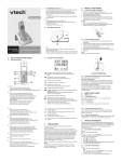
1
EuroCUT Professional 5
Manual
EUROCUT PROFESSIONAL
Important Customer Information
about EuroCUT Professional
Please check the contents of your software package as soon as
possible upon receiving it. Should any items be missing,
immediately contact the dealer from whom you have purchased
the software.
EuroCUT is available in three different versions:
EuroCUT Light, Basic and Professional
The three versions differ in their functions and in the contents of
the package.
All three versions include the EuroCUT Professional user manual,
in which all the functions of the different versions are described
in detail.
If some functions are described in the manual which are not
included in your version of EuroCUT, they do not belong to your
package.
A complete package of EuroCUT Professional should contain
the following items:
• 5 Program disks or 1 CD including EuroFONTER
• Copy protection key/dongle
• CD-ROM with 500 fonts
• User manual
• Registration card
Besides the program disks, the most crucial item is the copy
protection key/dongle. The number printed on the dongle must
match the serial number located inside the front cover of your
manual.
Underneath the dongle number, you will find your personal code
(e.g. 1234567,123456). This code number must be entered
upon successful installation and initial startup of the software.
Make sure you enter the number correctly, or you will not be able
to restart the program.
I
EUROCUT PROFESSIONAL
Important note: An update does not contain any of the
following: font disks, CD-ROMs, value pack or dongle.
II
EUROCUT PROFESSIONAL
Dear Customer,
In an effort to help you solve any problems and answer your
questions as quickly and efficiently as possible, we provide our
Technical Support Line. This is a toll free number you can call if
you have any technical questions about our products.
This service is available to you free of charge.
Mon. - Fri. from 9.00 am to 12.00 am
Mr Holz
Phone ++49 6502 9288 11
You can find further useful information including tips and tricks on
our web site:
http://www.eurosystems.lu
under the rubric Hotline & Support.
Our support staff have been instructed only to provide assistance
to registered users. When calling, faxing or e-mailing, please
provide the following information.
-
Dongle number of your EUROSYSTEMS product
Version number, i.e. EuroCUT Professional 5
Date of manufacture of your original program disks
Printout of your product’s file list (Help menu/menu item
About ...)
Please understand that we can only answer enquiries addressed
to this telephone number. Other telephone numbers are reserved
for marketing, purchasing and sales.
In order to obtain the best possible technical support, we urge
you to register your software. Immediately upon receipt of your
registration card by fax or online, you will be entered in our
Customer Support database. This allows us to keep you up-todate on revisions and upcoming products.
III
EUROCUT PROFESSIONAL
RCS Systemsteuerungen GmbH
General Distributor for EUROSYSTEMS products.
P.S. For written queries or instant registration by fax or online,
please use the following number or address:
Fax:
++49 6502 9288 15
Web site: h t t p : / / w w w . e u r o s y s t e m s . l u
IV
COPYRIGHT
Copyright
Copyright©1998 by EUROSYSTEMS S.à.r.l., Luxembourg. All
rights reserved.
The EuroCUT-Professional software for Windows and this
publication are licensed property of EUROSYSTEMS S.à.r.l,
Luxembourg, 3, rue Kummert L-6743 Grevenmacher. Any
reproduction or transmission in any form, by any method or for
any purpose of the software and of this manual, in whole or in
part, is strictly prohibited.
User manual text/ typesetting/ layout:
Peter Bettendorf, Georg Wagner
RCS Systemsteuerungen GmbH, Trier
English translation: Hilary Teske
This software is licensed for the exclusive use of the original
purchaser and is to be used on one computer system only.
Similar to a book, this software can be moved from one location
or computer to another, as long as there is no possibility of it
being used at two locations, or by more than one person,
simultaneously.
Exception: The above conditions do not apply for a multi-station
version or a EuroCUT Professional multi-user version.
The licensee may make one copy of the software for backup
purposes only.
Limitation of Liability
Utmost care has been taken in the compilation of this manual and
the text and illustrations therein; however, no guarantees can be
made as to the completeness or perfect accuracy of the manual
or the program itself.
In no event shall EUROSYSTEMS, its dealers or distributors, be
liable for lost profit, data, or information of any kind, or for any
special, collateral, incidental, consequential, indirect, punitive, or
any other type of damages in connection with or arising out of
purchase or use of EuroCUT for Windows or its documentation.
The information contained in this manual is subject to change
without notice and does not represent a commitment on the part
of the vendor.
V
COPYRIGHT
Trademarks
Adobe Type Manager, AMD, Intel, CorelDRAW, Postscript,
Microsoft, Windows, and other brand or product names used in
this manual are trademarks or registered trademarks of their
respective holders/ manufacturers.
V24.DLL
"The V24.DLL file is protected under copyright© 1992-1194
Langner GmbH. All rights reserved. The V24.DLL file may only be
used in conjunction with EuroCUT. Use with any other program,
as well as copying or distributing V24.DLL, is strictly prohibited".
February 2000
VI
ABOUT THIS MANUAL
About this Manual
Along with this manual, you have received the latest version of
EuroCUT, EuroCUT Professional. This version contains a host
of new features which will help you design all types of quality
signs and sign-related products with ease and confidence. The
drivers supplied with the program will assure high-quality output
from nearly all plotters available.
The manual is divided into nine chapters.
Chapter 1, How to Install EuroCUT describes the installation of
EuroCUT on your computer. Please follow the instructions
carefully since only proper execution of all procedures will assure
trouble-free setup and operation of EuroCUT.
Chapter 2, How to Work with EuroCUT Professional, is an
introduction to the basic use of this program.
Chapter 3, Sample Jobs, presents a series of signmaking jobs
designed to help you apply the procedures described in Chapter
2. The projects have been selected specifically to make use of
most features available in EuroCUT Professional. Following each
step and recreating it on your computer is a quick and easy way
to learn to work with EuroCUT.
This section also includes many tips and shortcuts which will
make working with EuroCUT even easier.
In Chapter 4, the Reference Section, all menus and menu items
are discussed in detail. Each function is described in
chronological order.
This section, as the name implies, is designed and laid out as a
reference manual. You should always refer to this part of the
manual first if you have questions or doubts regarding a specific
procedure.
Chapter 5, the Windows Overview, briefly describes all
elements of Windows with which the EuroCUT user should be
familiar to effectively use the program and the cutting device.
Chapter 6, the Kerning Editor, explains how to eliminate
unsightly gaps that often occur when individual characters are
placed next to each other to form a text string. Certain
combinations of characters have to be modified and the spacing
VII
ABOUT THIS MANUAL
adjusted so that the appearance of the typeface is more
harmonious.
Chapter 7, the EuroFONTER, explains how you can put an end
to the font chaos on your computer. This font management
program widens the scope of the Adobe Type Manager and
Windows font management and is especially suited for use with
Windows.
Chapter 8, Tips and Tricks, presents a selections of the
problems frequently addressed to our Hotline and Support and
describes possible solutions.
Hardware and Software Requirements
To use EuroCUT-Professional, you need the following equipment:
• 486 DX with a minimum of 8 MB of RAM; a Pentium 266 with
64 MB of RAM is recommended.
• Microsoft Windows version 95 or later
• Adobe Type Manager™ (ATM), Version 2.42 or later*
Note: If you are using Windows NT4.0 you can only use True
Type fonts.
• Video Display running at 800 x 600 with 16 colors
Incompatibilities
There are known incompatibilities with certain IBM computers
(Value Point Series 486 DX2/66 with PC-DOS prior to version
6.3) and with 386/40 computers from AMD. The processor
boards from these series of computers can create problems with
the co-processor.
Driver incompatibilities can occur with Logitech mice and some
high-resolution graphics cards from various manufacturers;
however, these problems can generally be eliminated by updating
the drivers.
VIII
ABOUT THIS MANUAL
User Manual Format
To make this manual more easily readable, the same symbols and
type styles are used throughout. The following is an explanatory
chart designed to help you find and interpret these visual aids
more easily.
Visual Aid Chart
Symbol / Type style
bold
Interpretation
Headings
Notes:
italic, bold, colon
italic
Note text
Menus, e.g. File menu functions, fields, options,
bold, italic
New command
commands, icons, e.g.
CAPITALS
Keys, e.g. SHIFT
KEY1+KEY 2
The plus sign (+) between two keys
means that you have to hold down the
first key when you press the second
key. Then you release both keys.
KEY1,KEY 2
A comma (,) between two keys means
that you press the keys one after the
other and release them.
Shortcut
IX
ABOUT THIS MANUAL
X
TABLE OF CONTENTS
Table of Contents
Introduction
1
1. How to Install EuroCUT
3
Single Work Station
3
Installing CoRun Auto Export Filter for CorelDRAW 6, 7, 8 & 9 and
EuroCUT Professional
6
Linking CoRun Macro (CorelDRAW™ 6) to the Toolbar
7
Linking CoRun Macro (CorelDRAW™ 7) to the Toolbar
7
Linking CoRun Macro (CorelDRAW™ 8) to the Toolbar
7
Linking CoRun Macro (CorelDRAW™ 9) to the Toolbar
Linking Corun Professional Script with the CorelDRAW 10 toolbar
9
9
Example of Data Transmission with CoRun
13
Installing EuroCUT Professional Using the MS-DOS 6.2x Operating System.
14
Installing EuroCUT Professional Using Windows NT
14
Network Installation
15
Multi-User Diskette
15
Site License
16
2. How to Work with EuroCUT
17
2.1 The EuroCUT Desktop With Working Area
17
Explanations of the Cursor Shapes in the Working Area
18
2.2 The Toolbox
19
2.2.1 The Arrow Tool
20
• Select
20
• Move
20
• Resize
20
2.2.2 The Node Editing Tool
• Round Nodes (inside/outside)
21
24
• Round outside corners
24
• Round inside corners
24
i
TABLE OF CONTENTS
• Reduce Nodes
25
• Symmetrical
25
• Cusp
25
• Smooth
25
• Origin
26
• Break
26
• Join
26
• Delete
26
• Add
27
• Curve
27
• Line
27
• Align
27
• Align Corners
28
• Direct Input of Coordinates for Node Positions
28
• Absolute Values
28
• Relative Values (with SHIFT key)
28
• Horizontal/Vertical Restriction in Drawing Lines/Curves
29
• Align Corners
29
• Round Corners
30
• Join With Straight Line
31
• Join With Curve
31
• Align Object Horizontally/Vertically
31
• Reduce Nodes...
32
Accuracy
32
Create Curves With Angle Larger Than – X - Degrees
32
Create Straight Line With Deviation Smaller Than – X – Degrees
33
• Node Selection
33
• Interactive Rounding or Aligning of Corners
33
2.2.3 The Zoom Tool
34
ii
TABLE OF CONTENTS
2.2.4 The Drawing Tools
36
2.2.5 The Text Editor
37
• Justify
37
• Font
38
• Caps Height
38
• Font Style
38
• Line Spacing
38
• Character Spacing
39
• Word Spacing
39
• Maximum Width
39
• High / Low
39
• Position
41
• Justification
42
• Radius
42
• Anchor Line
42
• Direction
42
• Options
43
• 12-Point Font
43
2.2.6 The Fill Function
45
Delete Gradient Fills or Bitmap Fills
45
Generate Gradient Fills
46
Determining the Gradient Fill
46
Generating Bitmap Fills
50
Selecting a Bitmap Fill
50
Tile
51
Seamless Tile
52
Adapt
52
Object Size
52
2.2.7 The Print Command
53
iii
TABLE OF CONTENTS
The Adapt Command
54
Mouse Functions in the Preview Window (Adapt Mode)
54
Print Area and Object
54
Printer
55
What is to be printed ?
55
Objects
55
Objects with Worksheet
56
Job Info
56
All Objects
56
Selected Objects
56
Printing Color-Separations
56
Printing of Single Colors (Layers)
56
Relation
56
Center
57
Tile
57
Number of Copies
57
1:1
57
Adapt
57
Print Colored Worksheet
57
Print Guidelines
57
Always Print Black
58
Register/Crop Marks
58
Buttons in the Print Dialog Box
59
The OK Button
59
The Cancel Button
59
The Print Bitmap Setup Button
59
The Tile Mode
60
Mouse Functions in the Preview Window (Tile Mode)
61
Example of Printing in the Tile Mode
61
iv
TABLE OF CONTENTS
Vertical and Horizontal Overlap
63
Activated and Deactivated Tiles
65
2.2.8 The Cutting Command
2.2.8.1 The Cutting Dialog Box
67
67
Why Use a Serial Plotter Drive ?
67
2.2.8.2 The Cutting Preview Window
72
The Options Menu
73
The Rotate Axis Command
73
The Horizontal (X) and Vertical (Y) Mirror Command
73
The Optimize Output Command
74
The Duplicate Command
76
The Position Command
77
The Recalculate Command
79
Original Display
79
The View Menu
79
The Material Width Command
79
The All Objects Command
79
The Display Selected Objects Command
79
The Total Area Command
79
2.2.8.2.1 Weeding Lines
81
The Options Menu
83
The Rotate Axis Command
83
The X and Y Mirror Command
83
The Optimize Command
84
The Duplicate Command
85
The Position Command
88
The Recalculate Command
90
Original Display
90
The View Menu in the Cutting Preview Window
90
v
TABLE OF CONTENTS
The Material Width Command
90
The All Objects Command
90
The Display Selected Objects Command
90
The Total Area Command
90
2.2.8.3 Job Sectioning in the Cutting Dialog
Modifying Sectioning
91
92
2.2.8.4 Color Separation in Cutting
92
2.2.8.5 Common Difficulties Encountered During the Cutting Process
94
a) Vinyl Bunches Up
94
b) Excessive Cutting Speed
94
c) Excessive Cutting Pressure
94
d) Insufficient Cutting Pressure
94
e) Excessive Cutting Depth
94
f) Dull Cutting Blade
95
g) Small Graphics Separate from Liner
95
h) Liner Cut Through
95
2.2.9 The Align Command
96
2.2.10 The Rotate Axis Tool
96
2.2.11 Other Tools
97
2.2.11.1 The Measuring Tool
97
2.2.11.2 The Outline Tool
99
2.2.11.3 The Welding Tool
101
2.2.11.4 Scanning and Vectorizing
105
2.2.11.4.1 Working with Color Bitmaps
107
2.2.11.4.2 Important Information on Scanning
109
2.2.11.5 The Engrave Command
110
1. Hatch Fill
111
2. Island Fill (Multi-Inline)
111
Tool
111
vi
TABLE OF CONTENTS
Hatch Angle
111
Path Adjustment
111
Overlap
112
Options
113
Target Layer
113
Engraving With or Without Frame
113
Engraving Depth
115
Pen Wait
116
Max. Depth Per Step in Mm (1mm = .0039 in)
117
Offset from Material
117
Reference Point
2.2.12 The Pencil Attributes Tool
117
119
Deleting Pencil Attributes
119
Creating Hairlines
119
The Pencil Attributes Dialog Box
119
2.2.13 The Color Layer Box
The Layer Setup Dialog Box
123
124
Routing Options
125
Layer Attributes
125
Layer Designation
125
Shortcuts in Layer Editing
126
2.3 The Object Attributes Box
2.3.1 Object Attributes-Dialog Box Options
127
128
2.3.1.1 Size
128
2.3.1.2 The Position Option
129
2.3.1.3 The Skew/Rotate Tool
131
2.3.1.4 The Duplicate Command
133
2.4 Import
CMX Import
134
135
vii
TABLE OF CONTENTS
2.5 Export
EPS Export with OPI Links
2.6 Load Jobs
137
139
141
2.6.1 Load from Job Manager
141
How to Use the Job Manager Window
142
Switching between Full Screen and Part Screen Modes
142
Job or Job Template
143
Selecting One or Several Jobs
143
Finding a Particular Job in the Job Manager Window
144
Updating Job Display
144
The Job Manager Menu
145
The Job Menu
145
• Load Jobs to EuroCUT
145
• Import to EuroCUT
145
• Job Info...
145
• Copy
145
• Move
145
• Delete
145
• Do Not Show Job
146
• Show Job
146
• Print List
146
• Print Images in Preview Window
146
• Enlarge Images
147
• Reduce Images
147
• Quit
147
The Settings Menu
147
• Job Manager
147
• Font
149
• Window in Front
149
viii
TABLE OF CONTENTS
The Find Job Menu
149
• Search Standard Paths
149
• Display Jobs in Standard Paths
150
• The History of the Optional Search Paths
150
The Help Menu
151
• About Finder
151
• Help
151
Description of the Right Mouse Button Menu
Non-Active Menu Items
The Key Functions in the Job Manager
2.6.2 Loading Without Job Manager
151
151
152
153
2.7 Save Jobs
155
2.8 Job Info
157
2.9 Job Calculation
159
Text Objects
159
The All Option
159
The Font Type+Material Option
160
The Font Size+Material Option
161
Graphics
162
The All Option
162
The Material Option
163
Special Characters
163
3. Sample Jobs
165
3.1 Sample Job 1
165
3.2 Sample Job 2
169
3.3 Sample Job 3
171
3.4 Sample Job 4
175
3.5 Sample Job 5
177
3.6 Sample Job 6
181
ix
TABLE OF CONTENTS
4. Reference Section
185
4.1 The File Menu
185
• The New…Command
185
• The New from Template Command
185
• The Job Manager…Command
185
• The Open…Command
185
• The Final Version Command
185
• The Save Command
185
• The Save As… Command
186
• The Online Service…Command
186
• The Import Command
186
• The Export Command
187
• The Print Command
187
• The Cut/Plot Command
187
• The Quit Command
187
• The Job Recall Function
187
4.2 The Edit Menu
189
• The Undo Command
189
• The Redo Command
189
• The Cut Command
189
• The Copy Command
189
• The Paste Command
189
• The Paste Contents... Command
190
• The Select All Command
191
• The Delete Command
191
• The Duplicate Command
191
• The Edit Text … Command
191
• The Text to Curves Command
192
• The Text to Lines Command
192
x
TABLE OF CONTENTS
• The Job Info… Command
192
• The Job Calculation… Command
192
• The Color Layer Box Command...
193
• The Ready to Cut ... Command
193
• Outline
193
• Gradient Fill
193
• Both
193
4.3 The Design Menu
194
• The Object Attributes ... Dialog Box
194
• The Rotate Axis Command
194
• The Horizontal Mirror Command
194
• The Vertical Mirror Command
194
• The Group Command
195
• The Ungroup Command
195
• The Combine Command
195
• The Break Apart Command
196
• The Fill Command
196
• The Without Command
196
• The Gradient Fill ... Command
196
• The Bitmap... Command
196
• The Layer Color... Command
196
• The Wireframe Command
196
• The Without Command
196
• The Hairline Command
197
• The Pencil Attributes Command
197
• The Mask Bitmap Command
197
• The Perspective Command
197
• New Perspective
197
• Lock Perspective
198
xi
TABLE OF CONTENTS
• Cancel Perspective
198
• The Envelope Command
198
• New Envelope
198
• Lock Envelope
199
• Cancel Envelope
200
• The Block Shadow Command
200
• The Drawing Tools
200
• The Line Mode
200
• The Arc Mode
201
• The Rectangle Mode
201
• The Circle Mode
202
• The Digitizing Mode
202
• The Freehand Drawing Mode
203
• Geometric Shapes…
203
• Register Marks
203
• Perforation Mark/Drill Hole
204
• The Align Command
204
• Clockwise Rotation of Objects
204
• Counter-Clockwise Rotation of Objects
204
• The Close Contour Command .
205
• The Open Contour Command
205
• The Round Corners Command
205
• The Optimize Nodes Command
205
4.4 The View Menu
207
• The Zoom In Command
207
• The Zoom Out Command
207
• The Full Page Command
207
• The Show All Command
207
• The Show Selected Object Command
208
xii
TABLE OF CONTENTS
• The To Front Command
208
• The To Back Command
208
• The Forward One Command
208
• The Back One Command
208
• The Reverse Order Command
208
• The Always in Front Command
208
• The Refresh Screen Command
209
4.5 The Tools Menu
210
• The Vectorizing … Function
210
• The Revectorizing Option
210
• The With Color Assignment Command
210
• The Contour Line .. Function
212
• The Scanning Command
217
• The Scanner Setup… Command
217
• The New Clipart Command
217
• The Clipart…Command
218
• The Insert Program …Command
218
• The Edit Program List...Command
218
• The Measure Command
219
• The Outline Function
219
• The Welding Command
219
• The Engrave Command
219
• The Use of Material Function
220
• The Text Editor
220
4.6 The Image Menu
221
• The Reduce Colors …Command
221
• The Posterize… Command
221
• The Grayscale... Command
222
• The Invert... Command
222
xiii
TABLE OF CONTENTS
• The Contrast…Command
222
• The Brightness... Command
222
• The Saturation... Command
222
• The Sharpness... Command
222
• The Gamma Correction… Command
222
• The Relief…Command
• EuroPhotoCUT
223
223
The EuroPhotoCUT Dialog Box
223
General Settings
224
Pixels in X Direction
224
Pixels in Y Direction
224
Remaining Width
224
Minimal Grayscale
224
Negative
225
Reverse Direction (only for lines)
225
Double (only for lines)
226
Horizontal or Vertical
227
Bitmap
227
Weed Aid
228
Create Weed Aid
228
Strap Width
228
Strap Thickness
228
Strap Offset to Weed Border
228
Stripes per Strap
229
Modes:
229
• The Convert to Bitmap Command
229
• The Attributes... Command
230
• Transparent Display of Images in Wireframe Mode
4.7 The Settings Menu
230
232
xiv
TABLE OF CONTENTS
Standard Settings
232
Misscellaneous
232
• Job Info
233
• Mouse
234
• Plotter
234
• Import
235
• The Color Palette Command
236
• New
237
• Load...
237
• Save
237
• Save as...
237
• Default
237
• Palette History
237
• The System Control Command
237
• Working Area
238
• The Rulers... Function
238
• The Measurement Unit Function
238
• The Grid Function
238
• Screen Colors
238
• Spot Colors
238
• 256 Color Dithering
239
• Windows Dithering
240
• The Edit Wireframe Mode
240
• The Draft Mode
240
• The Interrupt Display Command
240
• The Undo/Redo command
240
• The Cross-Hair
241
• The Snap to Guideline Command
241
• The Guidelines Setup Command
241
xv
TABLE OF CONTENTS
• The Lock Command
241
• The Show Guidelines Command
241
• The Show Tool Box Command
241
• The Show Layer Box Command
241
4.8 The Help Menu
242
• About EuroCUT©...
242
• Help...
242
• Info...
242
• Online Support
242
4.9 The Functions of the Right Mouse Button
243
5. Windows Overview
245
5.1 Control Panel
245
5.1.1 386 Enhanced
245
5.1.2 Ports
246
6. Kerning Editor
248
What is Kerning?
248
What Determines Kerning?
249
How are Kerning Factors Defined?
249
Why Use a Kerning Editor?
249
What are the Capabilities of Kerning Editor V2.1?
249
Installation with EuroCUT Professional
250
Launching the Kerning Editor
250
Operation
251
Kerning Window and Kerning Tools
251
Changing the Display Size
251
Selecting a Font
252
Selecting Character Combinations
252
Changing Kerning Values
252
Using the Sample Text Box
253
xvi
TABLE OF CONTENTS
Entering a New Kerning Pair
253
Deleting a Kerning Pair
254
Printing Font Data
254
Saving Kerning Data
254
Leaving the Kerning Editor
255
8. EuroFONTER
256
Preface
256
Range of functions
257
Notation
257
How the EuroFONTER Works
258
The EuroFONTER Desktop
258
Menu Bar
258
Tool Bar
258
Installed Fonts
258
Installed Catalogs
258
Open Catalogs
259
Fonts Contained in the List
259
Closed Catalogs
259
Sample Text Display
259
Status Bar
259
How to Work with EuroFONTER
260
Sample Job 1: Creating a Font Catalog, Assigning Fonts and
Generating an Initial Set of Fonts
261
Sample Job 2: Activation of Fonts on CD-ROMs
266
Sample Job 3: Cleaning Up the Hard Drive
268
Sample Job 4: Making Fonts Available to All Workstations on a File Server 272
Reference Section
274
Catalog
274
New
274
xvii
TABLE OF CONTENTS
Open
274
Close
274
Rename
274
Change drive name
275
Copy
276
Delete
276
Activate
277
Deactivate
278
Importing
280
Save as
281
Print catalog
281
Print font information
283
Quit
284
Font
284
Copy
284
Activate
284
Deactivate
284
Delete
285
Search to current catalog
285
Search to new catalog
286
Locate in all catalogs
286
Select
286
Select all
287
Information
287
Window
287
Cascade
287
Tile
287
Arrange catalogs
287
Close all
287
xviii
TABLE OF CONTENTS
Open all
287
Alias assignments
288
Settings
290
Basic settings
290
Standard font display
291
Large font display
292
Glossary
293
Drag & drop
293
FontCache
293
File Server
293
Catalog
293
Installed catalog
293
Standard font directories
293
EuroFONTER Shortcuts
294
9. EuroCUT Professional Tips & Tricks
296
Glossary
343
Index
349
Imprint
355
Appendix A
Appendix B
Appendix C
Appendix D
Appendix E
xix
INTRODUCTION
Introduction
Welcome to EuroCUT Professional, the innovative signmaking
software that will help you design all types of signs and signrelated products and cut them out of a variety of materials.
Whether you are new to sign-making or consider yourself an
expert, EuroCUT gives you all the tools you need for professional
results.
You will soon realize just how powerful EuroCUT is, whether your
application is display or vehicle graphics, signmaking, or exhibit
building. You may be involved in screen printing, vehicle lettering,
or stencil cutting EuroCUT is equally capable of handling any of
these tasks. And there are many more applications: e.g.
Stone masons,
wood working
Department stores
Film, photo and
TV studios
signage
Builders, architects
signage
Major corporations
exhibit displays
-
sandblasting applications
window displays
-
design of movie and TV-studios
theater props, directional
-
construction and architectural
-
interior and exterior signage,
Before you begin working with EuroCUT Professional, you should
be familiar with the basics of operating your PC and Microsoft
Windows.
A detailed description of the required procedures can be found in
your Microsoft Windows manual.
1
INTRODUCTION
2
Chapter 1
NSTALLATION
1. How to Install EuroCUT
Please follow
these
instructions
carefully to
ensure EuroCUT
The complete version 5 of EuroCUT Professional contains a total
is correctly
of 5 disks or 1 CD-ROM.
installed
Single Work Station
Step 1:
Step 2:
Plug the dongle supplied with EuroCUT into your
computer’s parallel port (or printer port LPT 1).
Secure the dongle by tightening the two screws.
Windows 95:
Choose the Port icon under icon under
Start/Settings/Control Panel/Device Manager.
Windows NT:
If you are using Windows NT as operating system you
will find the Port icon under: Start/Settings/Control
Panel.
Attaching the
dongle
Configuring
serial port
Windows 3.11:
Select Control Panel in the main menu of the
Windows program manager and click the Port icon.
A dialog box appears in which you can now select the
appropriate port (e.g. COM1) and parameters for your
plotter. The standard parameters are as follows:
Baud rate:
Data bits:
Parity:
Stop bits:
Flow control:
9600
8
none
1
hardware
Also make sure Advanced Settings for COM1 are
set as follows: the applicable I/O addresses for
COM1 are 03F8 and IRQ4; for COM2, 02F8 and
IRQ3.
3
INSTALLATION
Chapter 1
Step 3: Install the Adobe Type Set Value Pack.(not included)
From the Windows 3.11 Program Manager, select Run
in the File menu. Under Win95/ type B:\install or
A:\install in the command line box, depending on the
disk drive you intend to use.
Adobe Type
Manager
Installation
Step 4: Windows 95 and NT:
Select Run in the Start menu.
EuroCUT
Installation
Windows 3.11:
Start Windows and from the Program Manager select
Run in the File menu.
Start Windows and select Run in the File menu.
Note: Before you begin with the installation, please
make sure your DOS autoexec.bat file contains the
share.exe command. If this is not the case, the Share
command must be added. The easiest way to do this is
with the MS-DOS editor, edit.com.
Insert program disk 1 or CD-ROM in the appropriate
disk drive. Type A:\install or E:\install in the command
line box, depending on the disk drive you intend to use.
After a few seconds a window titled EuroCUT
Professional Setup appears.
To continue installation click the Continue button.
EUROSYSTEMS Licensing Agreement dialog box
Once you have confirmed that you accept the
EUROSYSTEMS licensing agreement, the actual
installation will start.
Start
Installation
Licensing
Agreement
Choose Target Path dialog box
In this dialog box you can select the directory in which
you wish to install EuroCUT Professional.
C:\Windows\Eurocut is usually proposed. If you wish to
install EuroCUT in another directory, click the Search
button and enter the desired target directory in the
upcoming dialog box under Path.
Choose Target
Path
4
Chapter 1
INSTALLATION
Type of Setup Dialog Box
Select Type of
Installation
There are three possible ways of installing EuroCUT
Professional.
Standard:
EuroCUT is completely installed. (This
method is recommended.)
Minimal:
Only the necessary functions of
EuroCUT are installed.
User defined: EuroCUT is installed according to the
user’s specifications, i.e. the user can
select the options he considers to be
important. This option is only
recommended for advanced users.
Note: This type of installation should also be selected
for installing drivers at a later date.
Select Program
Folder
Select Program Folder dialog box.
Here the default is the EUROSYSTEMS folder. You can
define a new program file by typing its name in the
command line.
Wait until you are asked to change the disk and then
follow the further instructions.
Changing disk
Ending Setup
End Setup Dialog Box.
If you click the End button in the Setup dialog box,
EuroCUT will be started and you will be asked to enter
your name and your code number.
Entering Your
Code Number
You will find your personal code number inside the
back cover of your manual.
Note: Please always type your complete code number,
including the comma.
Online
Registration
Once you have entered your personal code number,
EuroCUT will be started and the Online Registration
dialog box will appear.
5
INSTALLATION
Step 5 You are now ready to install your EuroCUT fonts via the
Adobe command atmcntrl.exe. To do this, open the
windows File menu, and click once again on Run. Enter
atmcntrl in the command line box. Then click on Add in
the ATM Control Panel. From the list of directories,
choose the font directory C:\psfonts\pfm. In the list of
Available Fonts, click and select all the fonts you wish
to install by keeping the left mouse button depressed.
Then click on Add in the ATM Control Panel. Finally,
increase the Font Cache to a minimum of 512 Kb
(1024 Kb is preferable).
Chapter 1
Installing
EuroCUT Fonts
You can also
select individual
fonts with CTRL
Step 6: Close all applications and restart your computer.
Start EuroCUT with a double click on the EuroCUT icon in the
EUROSYSTEMS panel.
Your EuroCUT software is now ready to go!
ID Sticker Information
1. Program name
2. Dongle number
3. Personal code number with version identification ( ), e.g. P
4. 7-digit code number +, (comma) + 6-digit number
Installing CoRun Auto Export Filter for
CorelDRAW 6, 7, 8 & 9 and EuroCUT
Professional
Note: The instructions on the following pages only apply to
EuroCUT Professional 5.2 and CorelDRAW 6, 7, 8 & 9.
In EuroCUT Professional data exchange between CorelDRAW 6,
7, 8, & 9 and all applications that are able to import and export the
CorelDRAW format are performed using drag & drop.
CoRun is not installed for CorelDRAW versions 3, 4, & 5.
Function: CoRun exports CorelDRAW data automatically – at
the touch of a button – to EuroCUT Professional.
System requirements: Win 95, 98 & NT, EuroCUT Professional
5.3, CorelDRAW 6, 7, 8 & 9.
6
INSTALLATION
Chapter 1
Note: To ensure that CoRun is properly installed make sure that
the Script Compiler is also installed when installing CorelDRAW
6. This is automatically carried out when standard installation is
selected.
CoRun is automatically installed on your hard drive when
complete installation of EuroCUT Professional 5.3 is selected.
Note: CoRun is not automatically integrated into CorelDRAW.
Linking CoRun Macro (CorelDRAW™ 6) to the
Toolbar
•
•
•
•
•
•
•
Select the Extras menu
Select Adjust
Select Symbol Bars
Double-click on General Script
Select corun 6.csc from the list of scripts
Choose any symbol you wish and drag it to the CorelDRAW
toolbar with the left mouse button held down.
Click on the OK button.
Linking CoRun Macro (CorelDRAW™ 7) to the
Toolbar
•
•
•
•
•
•
•
Select the Extras menu
Select Adjust
Select Symbol Bars
Double-click on Script Applications
Select corun 7.csc from the list of scripts
Choose any symbol you wish and drag it to the CorelDRAW
toolbar with the left mouse button held down.
Click on the OK button.
Linking CoRun Macro (CorelDRAW™ 8) to the
Toolbar
•
•
•
•
•
•
Select the Extras menu
Select Options
Select Working Area/Adjust/Symbol Bars
Double-click on Script Applications
Select corun 8.csc from the list of scripts
Choose any symbol you wish and drag it to the CorelDRAW
toolbar with the left mouse button held down.
7
INSTALLATION
•
Chapter 1
Click on the OK button.
8
INSTALLATION
Chapter 1
Linking CoRun Macro (CorelDRAW™ 9) to the
Toolbar
•
•
•
•
•
•
•
Select the Extras menu
Select Options
Select Working Area/Adjust/Symbol Bars
Double-click on Script Applications
Select corun 9.csc from the list of scripts
Choose any symbol you wish and drag it to the CorelDRAW
toolbar with the left mouse button held down.
Click on the OK button.
Linking Corun Professional Script with the
CorelDRAW 10 toolbar
Important note: CorelDRAW must be installed with the “Visual
Basic for Application.”
This option can be installed as follow:
Insert the CorelDRAW 10 CD in the disk drive / Start setup /
Select “Customize setup”.
If a CorelDRAW 10 version already installed on your computer,
first select ” User-defined setup” and then “Customize setup”. In
the dialog which now opens double-click on Main Applications
or click once on the Plus. Double-click on Productivity Tools
and select “Visual Basic for Application”. After installing Corun
you have to link the Corun script with the menubar.
•
Select the menu Tools/Adjustment
•
From the left-hand set of options select
Workspace/Customization/Commands
•
Click once in the File box on the right of the list of options,
select Macros and drag Corun10Prof.Corun... to the menubar
of CorelDRAW 10.
•
Now select the Appearance tab. Click on the Import button
and select any symbol you want.
•
Note: The symbol disappears every time you restart
CorelDRAW and the book-icon (standard default-icon)
appears. (CorelDRAW Bug)
9
INSTALLATION
•
From the left-hand set of options select
Workspace/Customization/Commands
•
Change the name of the”New sysmbol bar 1” to Corun
Professional.
•
Click OK in the Options dialog box
Chapter 1
Where can I find Corun in Freehand 8?
You can find Corun in Xtras under Animate and in the Window
menu/Xtras under Functions.
How can data be exported from Freehand to Corun ?
Sart Corun and if objects are selected, only the selected objects
will be exported to Corun.
Sart Corun and if no objects are selected, all object located in
your working area will be exported to Corun.
Restriction: Fountain fills and lens effects are not supported.
Note: Freehand 8 has a color correction mechanism (like, for
example, CorelDRAW)), which affects the display of colors in
Freehand.
Solution: Turn off this function via File/Setting/colors.
Where can I find Corun in Adobe Illustrator 8?
You can find Corun in the File menu under Export.
How can data be exported from Illustrator Corun ?
Sart Corun and if objects are selected, only the selected objects will be exported to
Corun. Any texts to be exported will automatically converted to curves.
Note: If no objects are selected, the CoRun auto export filter is not active.
Restriction: Special fountain fills are not exported.
Where can I find Corun in the various AutoCAD
versions?
Installation of Menu File for AutoCAD LT 98
10
INSTALLATION
Chapter 1
Select Adjust Menus in the Extras menu. In the dialog box
appearing click on the Scroll button. This opens the File
Selection dialog box. Set the file ending to *.mnu um. Select the
Corun.mnu file and close the dialog box.
Click on the Load button and then on OK in the enquiry dialog
box.
The Corun menu has now been loaded.
Now switch to the Menu Bar dialog box in the upper tab. Select
Corun Plot and insert it in the desired place in the AutoCAD
menu.
Corun is now to be found in the menu list and a Corun toolbar is
added to the toolbars.
Installation of the Menu File for AutoCAD R14
Select Adjust Menus in the Extras menu. In the dialog box
appearing click on the Scroll button. This opens the File
Selection dialog box. Set the file ending to *.mnu um. Select the
Corun.mnu file and close the dialog box.
Click on the Load button and then on OK in the enquiry dialog
box.
The Corun menu has now been loaded.
Now switch to the Menu Bar dialog box in the upper tab. Select
Corun Plot and insert it in the desired place in the AutoCAD
menu.
Corun is now to be found in the menu list and a Corun toolbar is
added to the toolbars.
Installation of the Menu File for AutoCAD 2000LT & 2000
Select Adjust Menus in the Extras menu. In the dialog box
appearing click on the Scroll button. This opens the File
Selection dialog box. Set the file ending to *.mnu um. Select the
Corun.mnu file and close the dialog box.
Click on the Load button and then on OK in the enquiry dialog
box.
The Corun menu has now been loaded.
Now switch to the Menu Bar dialog box in the upper tab. Select
Corun Plot and insert it in the desired place in the AutoCAD
menu.
Corun is now to be found in the menu list and a Corun toolbar is
added to the toolbars.
Installation of the Menu File for AutoCAD LT98 and R14
Select Printer Setup in the File menu. In the dialog box
appearing click on the Open button and select the
11
INSTALLATION
Chapter 1
Corun/t98.pc2 (LT98) file or Corunr14pc (R14) file. Quit the
dialog box.
Now start a printing job by clicking on Print in the File menu to
make the following settings:
Click on Plot to File, set the Resizing Factor to 1:1 and the
Unit to mm.
Note: Make sure the Plot To File checkbox is activated when
making the first plot.
This procedure ensures that all drawing elements are transmitted.
The Pen Change commands from the Plot file are interpreted so
that 8 layers can be separated.
AutoCAD does not plot with arcs, i.e. all elements are converted
into lines and dots are interpreted as drill holes.
Note: If you are using DXF, you have to press RETURN twice
after selecting the object, as the execution of the menu macros is
interrupted by the object selection.
Note: With export via DXF lettering and texts are not exported,
but it is possible to select objects and plot them. The curves are
not converted to lines but are changed from the splines or arcs in
the DXF file into Bezier curves.
Note: The number of layers is not restricted to 8.
In the Windows autostart group a connection to the autoimp.exe
program is made during installation, so that the data can be
exported to Corun. When autoimp.exe is started, an icon will be
displayed in the system bar at the bottom right of the screen.
The program can be ended by making a double click on this icon.
Note: If the icon is turned off, the data will not be exported to
Corun.
The program can be restarted via Start/Programs/Autostart/
Auto-Import for Corun.
Note: When installing, make sure that Corun for AutoCAD is only
installed for the last used AutoCAD version when several
AutoCAD versions are installed on your computer
12
INSTALLATION
Chapter 1
Example of Data Transmission with CoRun
Start CorelDRAW. Open, import or create a job. If the job
contains several objects and no object is selected, CoRun
transmits all objects to EuroCUT. If some objects are selected,
only the selected objects will be transmitted to EuroCUT.
Fig. 1: Job in the CorelDRAW Working Area
If you click on the CoRun button
EuroCUT is opened and
the imported job is displayed on the lower left of the EuroCUT
working area.
Note: Text objekts are automatically converted to curves using
CoRun.
Exception: Paragraph text has to be converted to artistic text
before being transmitted to EuroCUT.
13
INSTALLATION
Chapter 1
Fig. 2: Data imported with CoRun in the EuroCUT Working Area
Note: If various changes still have to be made to the job in
EuroCUT, the first step must be to break up the group (Object
menu, Ungroup).
Installing EuroCUT Professional Using the
MS-DOS 6.2x Operating System.
Before installing EuroCUT check that your system configuration
config.sys contains the entry _DEVICE=C:\DOS\HIMEM.SYS.
Make sure that the system directory (\DOS) and not Windows is
specified as the source directory for the himem.sys file. Without
this setup, the screen display and functioning of EuroCUT may be
considerably slowed down. You can use any text editor to edit
your config.sys.
Installing EuroCUT Professional Using
Windows NT
Install EuroCUT Professional as described in the installation
instructions.
Note: If you are using Windows NT an Adobe Type Manager
Deluxe 4.x has to be used so that the Adobe Type 1 fonts can be
properly managed. The Adobe Type Manager Deluxe 4.x is not
included in the EuroCUT Professional package
14
INSTALLATION
Chapter 1
Network Installation
If you intend to install EuroCUT on a computer network, the path
to the cutter.dat file must be modified to include read and write
options. This task should be left to your systems administrator.
The path to this file is variable and can therefore be adjusted to
meet any security requirements.
Using a text editor, this path can be modified in the eurocut.ini
file [JOB] section.
The EuroCUT Ini file is located in the EuroCUT directory following
a non-individual installation.
Multi-User Diskette
A special multi-user version of EuroCUT Professional is available.
The multi-user diskette contains design features only, without
cutting options.
This multi-user version can be installed on any networked station.
Provided a common data pool is set up on the network, multi-user
jobs can be sent to the output device via the main computer, i.e.
the one with the copy protection key or dongle.
The multi-user version is ideally suited for design workgroups. It
maximizes both the productivity of the workgroup and the
capabilities of any decentralized workstation.
The installation of a multi-user diskette is identical to the one
previously described for the complete version and requires
A:\setup or B:\setup (please see Installation, Step 5).
The multi-user diskette is not included in the standard package
but can be obtained from your dealer.
15
INSTALLATION
Chapter 1
Site License
When you purchase a EuroCUT site license, you obtain an
additional complete copy of the program, which can be installed
in a separate location from your main computer system.
Site licenses are particularly useful for branch or mobile systems.
This is a good way to circumvent order bottlenecks or facilitate
business expansions. Prerequisite for obtaining a site license is,
of course, a registered main license.
Installing a site license package is identical to installing the
complete EuroCUT program without font installation.
16
Chapter 2
WORKING WITH EUROCUT
2. How to Work with EuroCUT
2.1 The EuroCUT Desktop With Working Area
In this chapter you will learn the basics of working with EuroCUT.
You will be introduced to such items as the desktop, the tools, the
text editor, data import and export, loading and saving jobs, as
well as cutting.
After EuroCUT has been started, the following window appears:
* In EuroCUT the horizontal scroll bar and the status bar are
combined. The bar switches between the two functions when the
mouse cursor is directed to part of it.
A)
B)
C)
D)
E)
F)
G)
H)
I)
J.)
Symbol panel
Window title
Title bar
Symbol button
Full image button
End button
Toolbox
Menu line
Working area
Ruler buttons
1. Hair cursor on
2. Ruler on
3. Full color button
4. Grid on
5. Define working
area
K) Shadowing
L) Layer box
M) Grid/Line pattern
N) Vertical scroll bar
O) Desktop 30m x
30m/12 inch x 12
inch
P) Horizontal scroll bar
Q) Rules
R) Mouse coordinates*
S) Status bar*
T) Units of measurement
U) Direction of rotation
button
V) Stopwatch
W) Fill
The rulers can be positioned freely or completely turned off.
The units of measurement (cm, mm, inch) can be changed by
simply clicking a button. The button is located in the lower right
corner where the horizontal and vertical scroll bars meet.
In the status bar there is extensive information about the objects
to be found on the working area, such as wireframe, fill,
dimensions, number, combination or grouping.
The various elements in the menu line will be dealt with in detail in
Chapter 4, Reference Section.
17
WORKING WITH EUROCUT
Chapter 2
Explanations of the Cursor Shapes in the
Working Area
Cursor shape Explanation
No object selected
Note: You can select an object by positioning the mouse cursor
on it and pressing the left mouse cursor.
Move object
Note: This type of cursor is only active when the cursor is located
in the interior of the object or in the area between the 8 black
squares on the wireframe. The object must be selected.
Enlarge object vertically
Enlarge object horizontally
,
Enlarge object diagonally
Note: The cursors for changing the size of objects are only active
when the cursor is located in the area between the 8 black
squares on the wireframe of the object.
You can switch into the Skew/Rotate mode by clicking once on
the left mouse button with the cross cursor activated.
Cursor shape explanation
Object in Skew/Rotate mode
,
,
,
,
Rotate object
Skew object
18
Chapter 2
WORKING WITH EUROCUT
2.2 The Toolbox
STRG+1
Upon initial start-up of EuroCUT, you will find the toolbox in the
upper left corner of your screen. It contains 10 or more icons.
a.
b.
d.
c.
e.
Fig. 3: The EuroCUT Toolbox and its Flyout Menus
Click here to move the toolbox
Click here to close the toolbox
Click here to pull up the toolbox
a. Flyout Menu for the Zoom Tools
b. Flyout Menu for the Drawing Tools
c. Flyout Menu for the Fill Tools
d. Flyout Menu for Other Tools
e. Fly-Out Menu for the Pencil Tools
Note: Redisplay the toolbox via Toolbox On in the Settings
menu.
The toolbox can be moved at any time by clicking the bar at the
top and dragging it to the desired location. When you exit the
program, EuroCUT will save the last position of the toolbox.
19
WORKING WITH EUROCUT
Chapter 2
2.2.1 The Arrow Tool
Fig. 4: The Arrow Tool
The arrow tool, also known as the general work tool is used to
select, move, temporarily group and resize text or objects
• Select
Click on any point of the object and it is automatically selected,
i.e. a frame defined by eight small squares appears around it.
When working in the Edit Wireframe (F9)mode, you must click
on the outline of the object to select it
Note: To select individual characters in a text string, the text must
first be converted to an image by using the Text to Curves
command in the Edit menu. The selected letter(s) can then be
detached from the string by pressing SHIFT+L.
• Move
To move objects, simply select and drag them to the desired
location with the left mouse button.
• Resize
You can proportionally resize objects by grabbing one of the 4
handles or corner squares of the frame around the object.
Double-clicking on one of these corner squares opens the
Object Attributes...dialog box in which you may enter specific
values under Size.
To resize an object non-proportionally, double-click on the
squares located between the corner markers.
To resize by eye (proportionally or non-proportionally), simply grab
the appropriate square and drag it until the desired size has been
attained.
20
WORKING WITH EUROCUT
Chapter 2
2.2.2 The Node Editing Tool
The node or point editing tool lets you Move, Add, Join, Break
and Align nodes or points.
Fig. 5: The Node Button
Click on the node-editing button (the cursor changes its shape)
and subsequently on a point of the object or text string.
The text or object is now displayed as follows:
Fig. 6: An Object in the Node-Editing Mode
Tip: By hitting the SPACE BAR on your keyboard, you can easily
switch back and forth between the arrow tool and the nodeediting tool.
All corner points are displayed as squares, while all points on a
curve are displayed as circles. The latter are in fact called
tangential points.
The starting point of the object is displayed as a double square (a
smaller square inside a larger one).
To select individual nodes or tangential points, simply click on
them with the node-editing tool. To indicate selection, the points
are bolded (filled in). It is thus easier to recognize selected nodes
or tangents, which considerably facilitates node editing.
You can click on the different points and move them by pressing
down the left mouse button.
Moving a tangential point will reshape the corresponding curve.
Note: To select multiple points, click on the first point, then hold
down the SHIFT key while continuing to click on the other points.
21
Chapter 2
WORKING WITH EUROCUT
The same can be achieved by clicking a short distance away from
the first point and dragging a frame around it and all other points
you wish to select.
Double-clicking on a node activates the Node Editing dialog box.
The node-editing dialog box can be pinned firmly on the EuroCUT
working area using the
Pin icon When the Pin icon is
activated the pin turns into the symbol
becomes an Assign button.
and the OK button
Note: When you have pinned the Node Editing and Object
Attributes... boxes firmly on the working area, you can switch
back and forth between the boxes by hitting the SPACE BAR.
Fig. 7: Node Editing Dialog Box
Note: To edit the nodes in a text string, you first have to transform
the nodes into an image using the Text to Curves command,
otherwise the text string will be displayed with dotted blue lines.
You can recall the most frequently node editing commands via the
right mouse button.
The commands on the right mouse button change depending on
whether one or more nodes are selected.
If two nodes are selected, the right mouse menu appears as
follows:
22
WORKING WITH EUROCUT
Chapter 2
Fig. 8: The Right Mouse Menu With Two Nodes Selected
If only one node is selected, the following menu items are
available:
Fig. 9: The Right Mouse Menu With One Node Selected
Note: You can select several nodes by holding down the SHIFT
key and clicking on the nodes you wish to select one after
another.
23
WORKING WITH EUROCUT
• Round Nodes (inside/outside)
Chapter 2
U
Fig. 10: Rounding nodes
The following settings are available to you in the Round dialog:
• Round outside corners
When this button is activated, the selected nodes/corners or the
whole object will be rounded outside by the radius indicated,
depending on which option is chosen.
• Round inside corners
When this button is activated, the selected nodes/corners or the
whole object will be rounded inside by the radius indicated,
depending on which option is chosen.
The radius for rounding the nodes can be specified in the box on
the right next to the button mentioned above.
The option For Narrow Objects is located below the Round
button.
Two options are available to you.
If you select Use Small Radius, EuroCUT calculates the
appropriate radius for rounding the nodes on this narrow object.
If you select Do not round, the nodes on narrow objects are not
rounded.
24
WORKING WITH EUROCUT
Chapter 2
• Reduce Nodes
When this command is activated, any superfluous nodes will be
removed, i.e. the nodes which do not affect the shape of the curve
are removed.
Note: The Reduce function always affects the whole object.
• Symmetrical
Y
This command is used to make the tangents of any point perfectly
symmetrical, i.e. the two tangents of any curve point will form a
straight line and be of equal length. When moving such a node,
this symmetry will not be affected in any way.
• Cusp
P
The Cusp command cancels the symmetry of the tangents, thus
allowing you to change them individually. The shape of the curve
is not directly affected by the initial selection of this option.
• Smooth
Ä
This option is used to smooth points in a curve or wherever a
straight line turns into a curve. The tangents of these points are
adjusted so that they form a straight line, thus creating a perfectly
smooth curve or curve/straight-line transition for best possible
output quality. The adjustment of the tangents is always kept to a
minimum.
This feature is especially useful after moving a point on a curve.
Because any move causes the tangents to lose their orientation to
one another, the Smooth function must be used to readjust the
tangents to form a straight line. Again, this is a very important
editing feature in that it will determine the quality of your output
when you send it to your plotter/cutter.
Note: The Smooth option is not available when there are straight
lines on both sides of the selected points. When two tangential
points of a curve are moved, they are no longer symmetrically
aligned in relation to each other. The Smooth command
transforms them into a straight line again.
25
WORKING WITH EUROCUT
• Origin
Chapter 2
S
For routing applications it is important to be able to control the
point at which the bit first plunges into the material. This option
allows you to change the starting point of a selected contour,
which is of particular importance for routing and engraving
applications. For this type of cutting, it is important to be able to
control the point at which the bit first plunges into the material. To
change the starting point of a contour, double-click on the new
starting point you have selected. Choose Origin in the node
editing panel, and the selected point is turned into the new
starting point. As such, it is displayed as a double square.
• Break
T
This command is used to break up or dissolve a single point into
two separate points. Each of the new points will receive one of
the tangents of the original point. When applied to a closed
contour, this function will create two new points that become the
starting points for two open contours.
Select the point you wish to break. Double-click on it to activate
the node-editing panel. Click on Break.
• Join
This function, which joins two points, is used primarily to close
open contours. The points to be joined must be located at the end
of a segment or contour. With the node-editing tool, select the
first point. Then hold down the SHIFT key and select the second
point, i.e. the point you wish to join with the first. Selected nodes
are displayed with a black fill and the status bar shows you how
many objects have been selected. Finally click on the Join button.
J
Note: There is another option available for closing contours: the
Frame function. With the left mouse button held down, draw a
line linking the selected points. It is only possible to join two
selected points when they are both at the ends of an open
contour.
• Delete
To remove or delete nodes from your contour, you have the
following options:
Ö/DEL
-Select the point you wish to delete. Double-click on it and choose
the Delete command in the node editing panel.
26
WORKING WITH EUROCUT
Chapter 2
Or, more efficiently:
Select the point you wish to delete. Press the DELETE button on
your keyboard.
When deleting an end-point of an open contour, the adjoining
nodes will be connected with a curve, provided there was at least
one curve on either side of the deleted point.
However, if there were no curves on either side of the deleted
point (in other words, if you deleted a node on a straight line), the
adjoining points will be connected with a straight line.
• Add
I/INS
This function is used to add additional points to a contour line.
Use the node editing tool to double-click at the exact location on
the line or curve where you wish to insert a point. Click on Add in
the Node Editing panel that appears on the screen. A new point
has now been added to your contour.
• Curve
K
This command is used to convert straight lines into tangential
curves. Use the node-editing tool to select the line you wish to
convert and double-click on it. Choose the Curve command in the
node-editing panel and the straight line will be converted into a
curve.
• Line
G
This command is used to convert curves into straight lines. Use
the node-editing tool to select the curve you wish to convert and
double-click on it. Choose the Line command in the node editing
panel and the curve will be converted into a straight line. Note that
all curve attributes will disappear when a curve is converted to a
straight line.
• Align
V (vertical)
This function is used to vertically or horizontally align nodes or
points. You must select at least two points to perform this task.
With the node-editing tool, select the first point. Then hold down
the SHIFT key and select the second point, i.e. the point you wish
to align with the first one.
Double-click on the reference point, i.e. the point with which you
want the other selected point(s) to be aligned. Now select either
the horizontal or vertical Align icon in the node-editing panel.
H
(horizontal)
27
WORKING WITH EUROCUT
Chapter 2
• Align Corners
E
Aligning corners is a further possibility of aligning nodes or
points. This function aligns nodes which are positioned almost
vertically or horizontally in relation to the preceding and following
nodes.
Aligning corners is a combination of horizontal and vertical
alignment.
Right angles can be created very quíckly using this method.
Fig. 11: Aligning Corners
Figure 11 shows how Align Corners is performed. The original
state of the rectangle can be seen in the illustration on the left.
Select the lower left corner and open the Node menu by doubleclicking on the corner. The corner point will be aligned
horizontally and vertically with its adjacent points. This creates a
right angle, as illustrated in the diagram on the right.
• Direct Input of Coordinates for Node Positions
In the Position (mm) combobox you can position nodes by
entering their X/Y coordinates. A distinction is made here
between absolute and relative values.
• Absolute Values
When absolute values are entered the value is assigned to the
selected node.
• Relative Values (with SHIFT key)
When relative values are entered, the selected node is moved in a
horizontal or vertical direction by the amount specified in relation
to the selected node, i.e. the coordinates entered are added to
the original coordinates.
Procedure:
First enter the desired coordinates and then hold down the SHIFT
key while you click the Move button.
28
Chapter 2
WORKING WITH EUROCUT
• Horizontal/Vertical Restriction in Drawing
Lines/Curves
Lines can be restricted vertically or horizontally by holding down
the SHIFT key, i.e. it is only possible to move the line in one
direction.
original
moved
Fig. 12: Drawing Lines
When a curve is drawn, the curve is pulled out of shape. The
degree of distortion depends on the selected starting point, as
can be seen in Figure 13.
Fig. 13: Drawing Curves
Keys for node editing are also available on the keyboard.
The node attribute smooth is automatically saved when the
current and following node form a curve.
Note: The magnifying glass function can also be used in the node
editing mode.
• Align Corners
This command joins two nodes with two “smooth“ lines.
Any nodes situated between the two selected nodes will be
deleted.
29
WORKING WITH EUROCUT
Chapter 2
Strg + R
Fig. 14: Example of Aligning of Corners
This command joins two nodes with two “smooth“ curves.
Any nodes situated between the two selected nodes will be
deleted.
If one of the selected nodes is situated at a corner the original
angle will be retained.
• Round Corners
STRG + G
Fig. 15: Example of Rounding Corners
It can be seen in the figure above that the left outside edge of the
G needs modifying. To do this, select the nodes above and below
the “fault“. If you activate the Round Corners command, the
nodes situated between the selected nodes will be deleted and
the two points joined with a curve.
30
WORKING WITH EUROCUT
Chapter 2
You can see in the figure below that the selected points are
situated on parallel lines. If this is the case, the selected nodes
will be joined with a semi-circle. The nodes situated between the
selected nodes are deleted.
• Join With Straight Line
This command joins the two nodes selected with a straight line.
Any nodes situated between the selected nodes are deleted.
Fig. 16: Example of Joining Nodes with a Straight Line
• Join With Curve
The two selected nodes are joined with a curve.
Any nodes situated between the selected nodes will be deleted.
Fig. 17: Example of Joining Nodes with a Curve
• Align Object Horizontally/Vertically
The object in which the nodes are selected is aligned either
horizontally or vertically.
31
WORKING WITH EUROCUT
Chapter 2
Fig. 18: Align Object Horizontally
Fig. 19: Align Object Vertically
• Reduce Nodes...
When you activate this command, the Reduce Nodes dialog box
appears where you can make the following settings:
Fig. 20: Dialog Box for Setting the Accuracy of the Node Reduction
Accuracy
This value affects the conversion of lines into Bezier curves. The
greater the deviation is, the smaller the number of curve
commands that will be needed to recreate the original arc of the
curve.
Create Curves With Angle Larger Than – X - Degrees
If the angle of the lines at one of the nodes is smaller than this
value, the arc of the curve will be interrupted at this node.
32
WORKING WITH EUROCUT
Chapter 2
Create Straight Line With Deviation Smaller Than – X –
Degrees
If a curve is created with an arc lying within the tolerance value, it
will be converted to a straight line.
• Node Selection
TAB
TAB + SHIFT
BACK
BACK + SHIFT
Select next node
Select next node additionally
Select previous node
Deselect most recently selected node
• Interactive Rounding or Aligning of Corners
If you click on the arc of a curve with the CTRL key held down, a
node will be inserted at this place. This node serves to select the
position of the rounding. When the second node is selected, you
can align, round or perform any other node-editing command you
wish.
33
WORKING WITH EUROCUT
Chapter 2
2.2.3 The Zoom Tool
This function is used to zoom in and out on your desktop, working
area or design.
Fig. 21: The Zoom Function Icon
When you click on the Zoom icon, a flyout box appears
containing five additional icons.
Fig. 22: Flyout with 5 Zoom Functions
The icon with the plus sign is used to enlarge a selected area of
your desktop. Using the framing function, draw a frame around
the area you want to enlarge. You can repeat this procedure
several times for further magnification. An acoustic signal will
warn you when you have reached the limit and no further
magnification is possible.
Note: You can also activate this command by pressing F2 and the
+ (plus) key in the numeric keypad.
The icon with minus sign is used to reduce a selected area of
your desktop or working area.
Note: You can also activate this command by pressing F3 and the
- (minus) key in the numeric keypad.
The icon depicting a sheet of paper symbol is used to view the
working area in its entirety.
The icon depicting a monitor is used to display all objects in your
working area EuroCUT will enlarge or reduce the objects to make
just enough room for everything to fit on your screen.
The last icon depicting a magnifying glass is used to display all
selected objects as large as possible.
34
WORKING WITH EUROCUT
Chapter 2
Note: If you hold down the SHIFT key while executing this
command, only the selected objects will be enlarged to their
optimal size.
35
Chapter 2
WORKING WITH EUROCUT
2.2.4 The Drawing Tools
1.
2.
3.
4.
5.
6.
7.
8.
Fig. 23: The Drawing Tools
1. Straight lines
2. Rectangles and squares
3. Circles and ellipses
4. Digitizing mode
5. Curves
5. Freehand drawing
6. Stars and multi-cornered shapes
7. Drill holes
8. Register marks
Note: A detailed description of the Drawing tools is to be found
in the Reference Section.
36
WORKING WITH EUROCUT
Chapter 2
2.2.5 The Text Editor
Fig. 24: The Text Editor Icon
When you click on the T icon in the toolbox, an arrow with a
capital T appears on the screen. Use the tip of the arrow to select
the point where you wish to insert a text string. Clicking on that
point activates the Text Editor dialog box.
Note: A text string consisting of several lines will be divided into
separate lines when you quit the text editor. This makes it easier
to work on and edit the text.
Fig. 25: The Text Editor Dialog Box
• Justify
This field allows you to choose the appropriate justification for
your text string. A different selection is possible for each line of
text. First select the line you wish to justify. Now display the list of
available options and click on the type of justification you would
like.
Note: If you choose Forced Block, you must end each line of
text by pressing the ENTER/RETURN key.
37
WORKING WITH EUROCUT
Chapter 2
Character spacing will be extended in such a way that each line,
including the last, attains the maximum width you have selected. If
you instead select Block, do not end the line with ENTER/
RETURN. This will the cause the words to wrap and the spacing
to be extended so that the text (excluding the last line) will be both
left and right justified.
Note: Adjust Height of Caps enlarges or reduces the font size
depending on the line width. After such a modification has been
effected, the caps height is no longer displayed numerically; it
can, however, be verified with the Measuring tool.
• Font
This is where you choose the type of font you wish to use. First,
select your text string either by highlighting the portion of text you
want to edit (click at the starting point and highlight the
appropriate text portion with the mouse button held down) or by
pressing CTRL+A to select the entire text string. You can verify
the choice of font in the sample font display.
Note: You can select the entire text string by double-clicking in
the text input field.
• Caps Height
This field allows you to select a specific text height. The value
entered in this field always applies to the capital letters of the font
you have chosen. In the adjacent field, select the appropriate unit
of measurement.
• Font Style
The font style can be chosen by selecting one of the four icons in
the upper right-hand corner of the text editor dialog box; the
choices are normal, bold, italic and bold italic. It may be that not
all four selections are available for any given font. The available
options are always displayed in solid black while the rest are
grayed out.
• Line Spacing
Line spacing indicates the distance between text base lines. The
percentage value is based on the height of caps and is always
calculated from the baseline of the selected text line (i.e. the line
in which the cursor is located) to the preceding baseline.
38
WORKING WITH EUROCUT
Chapter 2
• Character Spacing
Character spacing indicates the distance between individual
characters in your text. A 100% value indicates the standard
kerning value. Values below 100% will condense, values above
100% will extend the text line. Instead of the percentage value,
you may also select various units of measurement.
• Word Spacing
This value defines the spacing between words in your text. The
value can be entered in millimeters, centimeters, or as a
percentage of the regular spacing.
• Maximum Width
This option allows you to set a maximum width for your text line.
Once you have reached the end of the line as defined by the
maximum, the text will roll over to the next line. When editing
existing text, you may change the maximum width for the entire
text or merely for one or more selected lines. Entering a smaller
value than the previous maximum for any given line will cause the
text to roll over sooner.
• High / Low
These two icons give you the option to place one or more
characters higher or lower than the normal text string while also
somewhat reducing their size.
The Special Character icon gives you access to many special
characters or symbols that, unless you know their SHIFT+
NUMBER sequences, cannot easily be entered via the keyboard.
To activate the Special Character window, click on the icon and
the list of characters available for the font you have selected will
appear.
39
WORKING WITH EUROCUT
Chapter 2
Fig. 26: First Half of the Special Characters (displayed in Arial font)
The left-hand option shows characters 0-127. They can also be
accessed over the keyboard. The right-hand option shows
characters 129-255. All characters can be transferred to the text
editor by clicking on them once.
Only characters available for the particular font you are using will
be displayed. The number of characters is generally an indication
of the quality of the font.
The TAB icon next to the Special Character icon in the text
editor dialog box allows you to set your own tabs for any line or
block of text.
Fig. 27: Tabulator Dialog Box
In the window on the left, all currently set tabs are listed.
To set a new tab, simply enter a value for the exact position at
which you would like to place it. Select the appropriate unit of
measurement in the adjacent box and click on Set to implement
the new tab.
40
WORKING WITH EUROCUT
Chapter 2
Position indicates the exact distance from the left margin of your
text.
Justification defines the justification of the text in relation to the
tab, i.e. left-justified, right-justified, centered or on a decimal.
When decimal justification is used, you can also determine where
the word is to be separated.
Edit allows you to change the position of any previously set
tab(s).
Delete removes any selected tab from the list.
The icon to the right of the Tabulator icon activates the Arc Text
function.
Fig. 28: Arc Text Dialog Box
In the upper left corner you will find the preview window.
The red arrow indicates the selected position of your text string
on the circle as well as the length of the text.
• Position
In the box to the right of the preview window you can change the
position of your text on the arc. You can choose between the
options right, top, left, bottom or manual. Selecting Manual gives
you the option to enter the exact angle at which your text will
41
WORKING WITH EUROCUT
Chapter 2
begin. To do this, simply enter a new value in the Angle field
below.
• Justification
This set of options allows you to specify how the text will be
placed in relation to point you have defined under Position
described above.
If you select Centered, for example, the text will be centered
around the previously defined point.
In the preview window you can view the Justification, Position
and Length of the text.
Adjust Caps Height will automatically increase or decrease the
height of your text proportionally to the size of the circle you have
selected. The larger the circle you have chosen, the larger the
letters and vice versa.
Adjust Spacing automatically adjusts the character spacing to
make it uniform.
The Opening Angle field is only active if you have previously
selected Adjust Spacing. It gives you the option to manually
adjust the spacing between each character
• Radius
This value defines the radius of the circle for the positioning of the
text block.
• Anchor Line
The six selection boxes in this window allow you to choose the
way in which your text will be placed on the circle.
The red line in each box represents the circle. To make your
selection, simply click on the appropriate box.
• Direction
This field is used to select the direction in which your text will arc
around the circle.
This option is also used to arc text inside a circle (use an angle of
180°).
42
WORKING WITH EUROCUT
Chapter 2
• Options
Maintain Skew: If you previously skewed your text, this option
will maintain the skew when you arc it.
Rotate Baseline: When you select this option, previously rotated
characters will not be rotated on the circle; instead, they will
maintain their rotation relative to a horizontal line even as they are
being arced on the circle.
Set Baseline on Circle: This will make the circle line your
baseline, i.e. the characters will actually be rotated on the circle
line.
Show Circle: This option will display the circle (which would
otherwise remain invisible) in your working area.
This will help you verify the selections you have made in the
Settings dialog box.
Cancel Arc: By clicking on this button you can cancel all
selections made and return the text to its previous form.
Note: The most efficient way to use the Arc Text function is by
setting up your right mouse button for immediate return to the text
editor.
You can do this in the Settings menu using Setup/Mouse. By
clicking twice on OK you can confirm the arc text which is drawn
in your working area. Clicking on the right mouse button allows
you to return to the text editor.
• 12-Point Font
If you select the 12-point font box in the text editor, your text string
will be displayed in a standard 12-point font. This feature is
intended to make text editing more efficient, since the 12-point
font is much easier to read.
3 clipboard functions let you exchange data with other programs.
icon deletes the selected text or characters from the
The
Text Entry field in the text editor and stores them in the Windows
clipboard.
43
WORKING WITH EUROCUT
Chapter 2
The
icon generates an exact copy of the selected text and
stores it in the Windows clipboard. The text is not removed from
the Text Entry field
The
icon restores previously cut or copied text from the
Windows clipboard in the Text Entry field. The restored text is
inserted immediately behind (to the left of) the cursor.
Save Settings stores all text editor selections you made as
standard parameters which will be recalled whenever you open
the text editor. This allows you to customize the text editor to meet
your specific design requirements.
Note: The text editor has a special function concerning the use of
the SPACE BAR.
You can insert a complete space between characters by hitting
the SPACE BAR once, half a space by pressing CTRL+SPACE
BAR, a quarter space by pressing SHIFT+SPACE BAR and an
eighth of a space by pressing CTRL+SHIFT+SPACE BAR.
44
Chapter 2
WORKING WITH EUROCUT
2.2.6 The Fill Function
This function allows you to fill objects with color or bitmaps. Their
are four options available to you:
Fig. 29: The Fill Icons
- moves all fills
- generates fills
- adds bitmaps
- assigns layer color as fill, when the object has a
gradient fill or a bitmap fill.
Delete Gradient Fills or Bitmap Fills
Fig. 30: The Delete Icon
When you click on this icon, gradient fills and bitmap fills are
removed from all selected objects. There remain only the
wireframes of the objects in the previously assigned layer color.
Example:
Original
black layer
red layer
45
WORKING WITH EUROCUT
Chapter 2
Lettering with gradient fills
Lettering after activation of the Delete button
Generate Gradient Fills
Fig. 31: The Gradient Fill Icon
Clicking on this icon opens the Gradient Fill dialog box, which
lets you determine the appearance of the gradient fills of closed
curves, text objects or combinations.
Fig. 32: The Gradient Fill Dialog Box
Determining the Gradient Fill
Enter the type of fill in the Type box. You can choose between
Linear, Radial, Conical and Square. The appearance of the
selected type is displayed in the preview box on the upper right.
46
WORKING WITH EUROCUT
Chapter 2
In the Steps Screen box, you can specify the number of gradient
stripes in the display on the screen.
Steps Printout specifies the corresponding number of gradient
stripes for output on a printer.
The Horizontal Center and Vertical Center boxes allow you to
determine the center of the gradient fill.
Note: These boxes are not active with the Linear type of fill.
If you enter 0%, the center of the fill exactly coincides with that of
the filled object.
The center can be moved to the right or left by 100% of the object
width or upwards or downwards by 100% of the object height.
You can also determine the starting point with the mouse. To do
this, move the mouse cursor over the preview box and click with
the left mouse button on the point which you wish to be the
starting point.
The Angle box determines if the shape of the fill stripes is linear,
conical or square. When Linear is selected, you can also
determine the angle of the fill using the preview window. Click on
any point in the window. Keep the mouse button held down and
move the mouse. A line with its starting point anchored down
appears and follows the movements of the mouse. After you
release the mouse button, the angles determined by the line will
be saved.
Note: The size of the margin can only be changed with linear and
square fills. The entered value - between 0% and 45% - specifies
the position of the first and last colors in relation to the center of
the fill.
Determining the Initial Color
The Gradient box allows you to determine the initial and final
colors and also the positions and colors of any intermediate
steps. The bar between the two triangles, the color gradient bar,
displays the color gradation.
To determine the initial color, click on the left-hand triangle.
To change the color, there are two possibilities available.
If you double-click on the Color box on the left of the color
palette, the Color Selection dialog box appears.
47
WORKING WITH EUROCUT
Chapter 2
Fig. 33: The Color Selection Dialog Box
The starting color can be changed using this window.
In the color palette on the left side of the window there are 256
predefined colors available to you. You can select a color by
simply clicking on the desired color with the left mouse button.
Further colors can be made visible by using the scroll bar to the
right of the color palette. You can select one of the colors for the
fill by simple clicking on the appropriate field.
To modify a color, double-click on the field in question. Then the
Color Selection dialog box described above appears so that you
can perform the change..
You can select a new color from the color palette on the right of
the Color Selection dialog box. If the color you want is not
visible, use the scroll bar to made it appear. You can specify the
color as starting color by simply clicking on the field in question.
If you double-click on the desired color box, this will reopen the
Color Selection dialog box so that you can choose the color.
The selected color is displayed in the Color box next to the
palette.
Selecting the Target Color and Further Color Gradations
To specify the target or final color in the fill, first click on the
triangle on the right side of the color gradient bar.
Now you can select a new color in the manner described above.
Further color gradations can be added by double-clicking on the
bar above the gradient bar.
48
WORKING WITH EUROCUT
Chapter 2
A small triangle showing the position of the color in the fill is
displayed at the selected position. The exact position is entered
as a percentage in the Position box.
49
WORKING WITH EUROCUT
Chapter 2
The position can be modified by moving the triangle or entering
the desired percentage in the Position box. To position the color
as you wish, first select the triangle which points to the position in
question. Then you can specify a new color in the ways described
above.
If you wish to delete one color gradation in the fill, click on the
triangle representing it. Then press the DEL key.
The triangle will disappear from the bar and the color is no longer
included in the fill.
Note: It is not possible to delete the starting and target colors in a
fill.
Generating Bitmap Fills
Fig. 40: The Bitmap Fill Icon
This command is used to open the Bitmap Fill dialog box, which
allows you to fill your objects with bitmaps.
Fig. 41: The Bitmap Fill Dialog Box
Selecting a Bitmap Fill
First you must determine the bitmap to be used to fill the selected
object. Three possibilities are available to you:
1. Scan in a New Bitmap Fill
Scan in the image to be used as a bitmap fill using the EuroCUT
Twain interface (Tools menu / menu item Scan).
50
WORKING WITH EUROCUT
Chapter 2
Open the Bitmap Fill dialog box.
The selected bitmap will be displayed in the preview window and
also appears in the box headed
Available Bitmaps.
Make your settings and click on OK to confirm.
If the result is not to your satisfaction, you have the possibility to
“detach“ the bitmap and restore the scanned in image to its
original state.
To restore the original image, choose the menu item Detach
Bitmap in the Edit menu.
2. Import New Bitmap Fill
To select a new bitmap as fill, click on Import Bitmap Fill. A File
Selection dialog box will appear, which allows you to look for
and select the desired bitmap.
The selected bitmap will then be displayed in the preview window
and also appears in the bar with the available bitmaps in the lower
left of the dialog.
3. Add Used Bitmap Fill
If you wish to make use of a bitmap fill which has already been
used, select the desired bitmap from the list of available bitmaps
by simply clicking on it with the mouse.
To make bitmaps not displayed appear, you can use the scroll bar
in the lower right part of the screen.
Choose the type of bitmap fill you want in the Fill Mode box. The
possibilities are Tile, Seamless Tile, Adapt and Object Size.
Tile
The Tile command fills the object with tiles drawn next to and
below each other from the selected bitmap fill.
The width and height of a single tile can be specified in the
appropriate boxes in the measurements group.
Tick the Proportional box to ensure that, when either the height
or width is modified, the other value is also adjusted
proportionally to avoid the bitmap being distorted.
If you activate Scale with Object, the measurements of the tiles
will be automatically adjusted in the case of a distortion.
51
WORKING WITH EUROCUT
Chapter 2
Tiling normally starts in the upper left corner of the object. With
the aid of the X Position and Y Position boxes you have the
possibility of changing the starting point. Enter a negative value
between 0% and 100% to move the tile to the left or right.
If you enter a positive value between 0% and 100% the center of
the first tile will be moved either to the right or downwards.
If you select Move, you can move the tiles within the rows. To X
and To Y allow you to specify if you wish to move the tiles in a
horizontal or vertical direction. You can enter the size of the move
in the box on the right as a percentage of either the tile width or
height.
Seamless Tile
Seamless Tile is basically the same as Tile. The only difference
is the way the tiles are represented.
With seamless tiling the squares are all drawn with exactly the
same measurements. This produces a more even picture
especially with patterns.
The drawback of this method is that the position of the tiles can
vary when the view is magnified.
Adapt
If you use the Adapt command the bitmap is only drawn once in
the object. The preview window displays the exacts proportions of
the bitmap and the object..
In the Width and Height boxes you can specify how large the
bitmap fill is to be.
In the X Center and Y Center boxes you can determine how far
the center of the bitmap is from the center of the object as a
percentage.
You can also specify this position using the preview window.
Click on the bitmap in the preview window and hold down the
mouse button.
You can then position the image by moving the mouse. When you
release the mouse button, the image will remain in the selected
position.
Object Size
This command adapts the bitmap exactly to the contours of the
object. The width and height of the object are calculated so that
the entire area of the object is filled.
52
WORKING WITH EUROCUT
Chapter 2
2.2.7 The Print Command
Fig. 42: The Print Icon
The following sections describe the various functions of the
EuroCUT Print dialog box in detail.
Open the EuroCUT Print dialog box by selecting Print in the
File menu, using the shortcut CTRL+P on the keyboard or
clicking on
the
icon in the tool box.
The following window opens:
Fig. 43: The EuroCUT Print Dialog Box
In the lower right part of the dialog you will find under Output the
Tile option and the Adapt button.
The appearance of the Print dialog box changes depending on
which button you have activated. When the Print dialog box is
selected, the Adapt button is automatically activated, because
53
WORKING WITH EUROCUT
Chapter 2
objects or graphics cannot be printed in formats exceeding the
maximum output size of the printer being used.
The Adapt Command
The Adapt command let you specify the printable area. The
values for the printable area are shown in the Print Area box
located in the upper right part of the Print dialog box.
The Preview Window in the Adapt Mode
This window allows you to recheck your job before it is printed.
The Snap to Edge function permits you to position your objects
quickly in the corners or at the edges of pages.
Tip: If you want to turn off the Snap to Edge function, hold down
the SHIFT key while you position your objects.
The coordinates appearing below the preview window show the
position of the upper left corner of the first object in the working
area.
Mouse Functions in the Preview Window (Adapt
Mode)
Clicking once with the right mouse button enlarges the preview
window to its maximum size.
The size of the display depends on the screen resolution.
(800*600, 1024*768,...).
If you click again with the right mouse button the original state is
restored.
If you press and hold down the left mouse button, a dotted black
frame appears around the objects to be printed.
This frame encompasses all objects to be found on the working
area and corresponds to the print area.
Print Area and Object
In the upper right part of the Print dialog box you will find the
items Printing Area and Object.
Fig. 44: Print Area and Object
54
WORKING WITH EUROCUT
Chapter 2
Printing Area
This box shows the height and width of the specified printing
area.
Object
This box displays the object(s) to be printed with its/their heights
and widths.
Note: The boxes for the percental enlargement of objects are not
active in the Adapt mode.
Below the Object Attributes... field, on the right side of the
Print dialog, you will see the Printer field.
Printer
Fig. 45: Choice of Printer
If you open the combobox in the upper part of the dialog box, you
will obtain a list of all the printers installed on your system. Select
the printer you wish to use.
To make further settings for the printout, click on the Setup
button.
The dialog which appears is the same as the menu item
Attributes in the Printer File menu.
Note: The Print dialog box opened by clicking the Setup button
depends on the printer driver loaded and for this reason is not
explained in greater detail here.
You can specify the Page Format (upright/oblong) in the field to
the right of the Setup button.
What is to be printed ?
In the field headed Print Mode there are two comboboxes which
you can use to determine what is to be printed.
In the first box you can choose between Objects, Objects with
Worksheet and Job Info.
Objects
All Objects in the working area will be printed.
55
WORKING WITH EUROCUT
Chapter 2
Objects with Worksheet
All objects and also the worksheet (black frame) will be printed.
The company name, the measurements of the working area and
the proportional size of the printout will also be printed
automatically below the black frame.
Job Info
If you click on this item, the information in Job Info will be printed
and also all objects in the lower right part of the sheet will be
printed on a reduced scale.
The following settings are available in the second box: All
Objects, Selected Objects, Print Color Separations (print in
layer order), Print Single Layers (colors).
All Objects
All objects on the working area will be printed.
Selected Objects
Only selected objects on the working area will be printed.
Printing Color-Separations
All objects of one color will be printed in the order displayed.
The color bar (layer order) in the second box contains all the
colors (layers) which have been used in the working area. The
colors will later be printed in this sequence. The darkest color is
always printed first.
Printing of Single Colors (Layers)
The colors listed in the second box are those which have been
used for the objects in the working area.
If, for example, there is only a black and a red object in the
working area, there will be a choice of only two color bars (layers)
available.
Relation
You can enter the relation in which the printout should be made in
one of two boxes, either as a figure or a percentage.
The boxes are coupled, i.e. if you enter a figure, the equivalent
percentage will automatically appear in the box provided and vice
versa.
56
WORKING WITH EUROCUT
Chapter 2
.
Examples of relation entries in figures with the corresponding
percentages:
Relation
Relation
Relation
Relation
1 : 1 100.00 %
1 : 2 50.00 %
1 : 3 33.33 %
1 : 4 25.00 %
Center
If this option is activated, all objects on the working area will be
centered.
Tile
If this option is selected, the Print dialog box appears in the Tile
mode.
Number of Copies
In this box the number (max. 9999) of copies to be printed can be
specified.
The Adapt and Tile buttons permit you to switch to and fro
between these two modes.
1:1
When this button is activated, all objects on the working area will
be displayed in their original size.
Adapt
When this button is activated, the objects in the working area are
reduced so that they can be shown in their entirety in the preview
window.
Print Colored Worksheet
If this option is selected, your worksheet will be printed with the
specified background color.
Print Guidelines
If the job contains guidelines, these will also be printed.
57
WORKING WITH EUROCUT
Chapter 2
Always Print Black
This option will automatically be activated when All Objects is
selected in the first box and Print Color Separations (in layer
sequence) or Print Single Colors (single layers) is selected in
the second box.
This option is automatically activated when you select All
Objects in the first box and Print Color Separations (in
sequence of layers) or Print Single Colors in the second box.
If you want to print the objects in the working area in color, the
command must be deactivated.
Register/Crop Marks
This option will automatically be activated when All Objects is
selected in the first box and Print Color Separations (in layer
sequence) or Print Single Colors (single layers) is selected in
the second box
If you do not want the register/crop marks to be printed, the
Register/Crop Marks button must be deactivated beforehand.
The following table shows all possible combinations for
comboboxes 1 and 2 and the possible choice of settings in the
Adapt mode.
Fig. 46: Possible Settings in the Adapt Mode
58
WORKING WITH EUROCUT
Chapter 2
Buttons in the Print Dialog Box
The OK Button
If you click on this button the settings made will be transmitted to
the printing device.
The Cancel Button
You can use this button to quit the Print dialog.
The Print Bitmap Setup Button
Clicking on this button opens the following dialog box:
Fig. 47: The Color Printing Options Dialog Box
This dialog lets you determine the Print Density (dpi) and the
Color Depth (bits per pixel) for the printing of bitmaps.
Use the Apply button to determine whether these values are to
be used or not.
59
WORKING WITH EUROCUT
Chapter 2
The Tile Mode
If you switch from the Adjust mode to the Tile mode, the
following preview window appears:
Fig. 48: The Preview Window in the Tile Mode
In the Tile mode all tiles are displayed. A tile is the part of an
object which can be printed or cut on the device being
addressed.
Break After indicates after which tile (enter the number of the
tile) the output should be stopped. You can enter the desired
horizontal/vertical intersection of the objects to be printed in the
boxes under the menu item Overlap.
If you print using Roll, complete stretches can be printed without
any spaces between the single tiles.
You can only stop the printing of a complete stretch and not of
the individual tiles.
Entering an intersection in the printing direction does not have
any effect on this operation, as can also be seen from the display
of the tile size.
60
WORKING WITH EUROCUT
Chapter 2
Note: After tiling the dialog will not automatically be closed, as it
is useful to be able to compare the preview directly with output.
This also allows you reprint a particular tile immediately.
Mouse Functions in the Preview Window (Tile Mode)
You can enlarge the tiling view to the size of the screen by
clicking once with the right mouse button on the tile preview
window. A second click with the right mouse button will restore
the original state.
Double-clicking with the left mouse button on a tile deactivates
the tile, i.e. it is not printed.
If you double-click with the left mouse button while holding down
the CTRL key, the tiling will be inverted, i.e. the tiles which were
previously deactivated will be activated (printed) and the tiles
which were activated will be deactivated (not printed).
The objects can be moved within the preview window using the
mouse. The Snap to Edge function enables you to position your
objects easily at the edge of the window. You can turn off the
Snap to Edge function by pressing the SHIFT key.
Example of Printing in the Tile Mode
In the following example, the various functions, shortcuts, etc. in
the Tile mode are explained again in detail.
The Tile mode offers you the possibility of printing in any size, i.e.
any image, regardless of its size, can be printed out on the printer
connected to your system.
To print your image, you do not require a printer for printing A2,
A1, A0 or even large formats.
How can this be done?
The image to be printed is divided into as many partitions (tiles) as
necessary to be able to print it on the printer connected to your
system. .
The number of tiles necessary depends on the size of the image
to be printed and the output format (A3, A2, etc.) which has been
specified.
You can determine the output format using the Setup button in
the EuroCUT Print dialog box. The format depends on the printer
which is connected to your system.
61
WORKING WITH EUROCUT
Chapter 2
Load any graphic you like to EuroCUT Professional and open the
Print dialog box, either by clicking Print in the File menu, by
pressing CTRL+P on the keyboard or by using the button in the
toolbox.
The EuroCUT Print dialog box will be opened in the Adapt
mode.
Activate the Tile mode by clicking the appropriate button.
The Print dialog box appears as follows:
Fig. 49: The Print Dialog Box in the Tile Mode
In the upper right corner of the dialog box you will see two fields,
Tile and Object. The Tile field corresponds to the Printing Area
box in the Adapt mode. The other fields in the right half of the
Print dialog box behave in the same manner as in the Adapt
mode.
62
WORKING WITH EUROCUT
Chapter 2
In Figure 49 you can see the preview window in the Tile mode.
Fig. 50: The Preview Window in the Tile Mode
The preview window in the Tile mode shows all the tiles which are
required so as to be able to print out the complete image.
Eight pages, for instance, are required to be able to print out the
image in the example.
A change in the output format always necessitates an adjustment
in the number of tiles.
Beneath the preview window you will find the fields Break After,
Tiling and Roll, which are explained on page 46 of the manual.
Vertical and Horizontal Overlap
The number of tiles increases depending on the number of
vertical or horizontal overlaps which you have specified.
This is illustrated by the following example:
Figure 51 shows two tiles to be printed without any overlap.
63
WORKING WITH EUROCUT
Chapter 2
Fig. 51: Two Tiles without Overlap
Fig. 52: Four Tiles with Overlap
Figure 52 shows that the number of tiles increases when you use
an overlap.
64
Chapter 2
WORKING WITH EUROCUT
Activated and Deactivated Tiles
An active tile means a tile which is not marked with an X,
whereas deactivated tiles are always marked with an X.
1
3
5
2
4
6
Fig. 53: Deactivated Tile
Tiles can be deactivated or activated by double-clicking on them
with the left mouse button, i.e. a tile is deactivated with a double
click. A further double click will reactivate it.
You can see from Figure 53 that tile number 4 is marked with an
X. This tile has been deactivated and will not be printed.
In the Tile mode you have a further possibility besides activating
or deactivating single tiles.
If you hold down the CTRL key while double-clicking on the
desired tile with the left mouse button, all tiles, except the one on
which the mouse cursor is positioned, will be deactivated.
Figures 54 and 55 illustrate this.
65
WORKING WITH EUROCUT
Chapter 2
Mousecursor
Fig. 54: Six Tiles Active (Mouse Cursor is on Tile 4)
Fig. 55: Tiles 1, 2, 3, 5 and 6 Deactivated, Tile 4 Activated
Advantage of deactivating tiles:
When your objects are arranged, tiles without objects (empty
tiles) may be created, which would result in a blank page being
printed.
66
WORKING WITH EUROCUT
Chapter 2
2.2.8 The Cutting Command
This command allows you to activate the module for cutting and
drawing your job data.
2.2.8.1 The Cutting Dialog Box
Fig. 56: The EuroCUT Cutting Dialog Box
In the box titled Plotter/Driver select the device that is
connected to your serial port.
Why Use a Serial Plotter Drive ?
The serial RS 232 port is the link for data exchange between the
cutting plotter and the so-called host computer.
The host computer calculates the necessary plotting data
decentrally.
Two-way or bidirectional communication takes place between
the host computer and the cutting plotter via a hardware
handshake. There is a separate data lead for this handshake in
the original cable supplied by the plotter manufacturer. The
centronics port, i.e. the parallel (printer) port, only permits oneway or unidirectional communication between the host computer
and plotter.
The cutting plotter can receive, but not cut, data using this port.
Thus, when using this port, it not possible to specify the vinyl
width, vary the stabbing pressure or reduce the cutting speed.
Only one port at a time can be active, in this case the plotter, as it
receives the data first.
Besides this purely technical difference, there is another
important reason, which is the different distribution of resources
with computers using MS Windows 3.xx.
67
WORKING WITH EUROCUT
Chapter 2
Whereas serial drive lets you go on working during plotting, the
computer is blocked all the time during plotting, when parallel
drive is used.
In this case serial drive means higher productivity.
In the Mode box, select whether you want to draw or cut with
your device.
Under Port select the port to which your cutting plotter is
connected. This is usually COM2.
In this box you can also choose File. This selection allows you to
send the output data to a file specified by you and the data will be
saved on your hard drive.
In the boxes Material/Vinyl, Pressure, Speed/Velocity and
Width you can enter specific values for the material you are
using. This values have to be entered individually, as they depend
on the material and the machine you are using.
The range of values are described in your plotter manual.
For example, the maximum speed is 60 cm/sec, i.e. 60 should be
entered under Speed/Velocity. Other plotter manufacturers use
mm/sec as unit of measurement. In this case a three-digit figure
has to be entered, e.g. 150.
To install a new set of material data in the material databank,
proceed as follows:
Click with the left mouse button on the New button below the
Material/Vinyl box.
Enter the description of the material, e.g. Mactac, 3M, PMF,
paper, etc. and specify its attributes regarding pressure, speed
and width.
If you keep the SHIFT key pressed down while you click on the
buttons, the current set of data will be saved as a new set of data.
This is useful when you only want to make small changes, such as
different pressure, in the current entries.
You can save the data by clicking Save.
The Delete button gives you the possibility of deleting individual
sets of data again.
Note: The settings in this dialog box will be automatically saved
when the Cut/Draw button is activated.
68
WORKING WITH EUROCUT
Chapter 2
The Options button lets you set routing parameters and cannot
be activated when you are using the cutting plotter.
With a lot of cutting plotters the Read Back button indicates the
height of the plottable area so that the value for width does not
have to be entered manually.
If you are using a device which does not offer this option, no value
or a zero will be indicated.
In the Number of Copies box you can specify how often the
selected objects are to be cut. After cutting, this value will be
automatically reset to 1.
Stack Offset lets you define whether the copies are to be
stacked vertically. This option can only be activated if it is possible
to cut the selected object more than once on top of each other.
In the stack preview the first object will be displayed in its
“normal“ state. Every further object in the stack will be shown with
a black square containing an X.
Fig. 57: Objects in the Stack Preview
Note: When this option is selected, the lower part of the cutting
dialog shows how often the images in the job will fit on top of
each other and how many meters of vinyl will be needed.
Weeding Frame allows you to specify whether a rectangle will
be cut around the plot and at what distance so as to make it
easier to strip or weed the vinyl.
With Segment Offset you can specify the horizontal distance
between single segments.
69
WORKING WITH EUROCUT
Chapter 2
If you select the Sort function, all objects located on the working
area will be sorted in X direction when they are cut.
Fig. 58: The Sort Function in the Cutting Dialog Box
In Figure 58 you can see 6 objects which have been created in
numerical order.
First object 1 was created, then object 2, etc. If the Sort function
is not active, first object 1, then object 2, etc. will be cut, i.e. long
distances will have to be covered when cutting. This can cause
the vinyl to become displaced and takes too much time.
If Sort is active, first object 3, then 6, then 5, etc. will be cut. With
this variation, the plotter covers the shortest distance possible.
If the Stack Processing option is activated, all the jobs will be
processed one after another without any break.
Note: The Cutter symbol is not active when this option is
selected.
If your image is too big for cutting, EuroCUT will divide it into as
many segments as are necessary for it to be cut in its entirety.
If you select the option Wait after Segment the cutting
procedure will be interrupted after each segment and the vinyl
can be repositioned if necessary.
Note: This function is not suitable for plotters which have a small
cutting width or for flatbed plotters.
70
WORKING WITH EUROCUT
Chapter 2
Fig. 59: Example of Segmentation (Cutting Width 1.50m/59 ins)
The physical zero point (0/0) of the plotter or router can be set
using the Sheet Origin function.
If this function is turned off, EuroCUT automatically chooses the
physical zero point as the starting point for cutting or routing.
Fig. 60: Sheet Origin not Active
If Sheet Origin is activated, the physical zero point is moved by
the amount of the offset coordinates of the point of reference.
The coordinates of the point of reference correspond to the
position of the lower left corner of the object to be cut on the
EuroCUT working area.
Fig. 61: Sheet Origin Active
You can turn the cutting preview on and off using the Cutting
Preview option, if you have previously activated this option in the
plotter setup (Settings menu, menu item Basic Settings).
Note: If the Cutting Preview option has not been activated in
the plotter setup, this box appears with a gray background.
71
WORKING WITH EUROCUT
Chapter 2
2.2.8.2 The Cutting Preview Window
The Cutting Preview window is automatically opened when you
click the Cut button.
Fig. 62: The Cutting Preview Window in the EuroCUT Cutting Dialog
The various functions available to you in this dialog box are
explained in detail in the following sections.
The following information about the job to be cut is shown in the
Cutting Preview window status bar:
Wireframe, fill, width and height, group or combination and the
maximum amount of vinyl used in square meters and continuous
meters.
When the Cut menu is selected, the data are transmitted to the
cutting device.
Note: If the job to be cut is located to the left of, above or below
the vinyl preview window and the Cut menu is activated, you will
be automatically informed that the objects to be cut are outside
the cutting area.
The ESC key allows you to quit the Cutting Preview dialog box
and return to the EuroCUT working area.
72
WORKING WITH EUROCUT
Chapter 2
The Options Menu
The Rotate Axis Command
This command is used to rotate objects by 90°.
If this command is performed several times in succession, the
selected image will be rotated 90° each time.
Fig. 63: Example of Axis Rotation
The Horizontal (X) and Vertical (Y) Mirror Command
The X Mirror command mirrors all selected objects on the
horizontal axis. The Y Mirror command mirrors all selected
objects on the vertical axis.
Fig. 64: Example of the Mirror Command
73
WORKING WITH EUROCUT
Chapter 2
The Optimize Output Command
When you click this menu item, the dialog for optimizing the use
of the vinyl opens.
Fig. 65: Dialog for Optimizing Vinyl Use
This function ensures that all the objects are arranged in such a
way that they take up as little space as possible on the vinyl.
The following options are available to you in this dialog:
Weed Border
If you check this option, a weed border will be cut automatically
around your job to facilitate weeding. Enter a value for the
distance at which you would like to have the weed border cut.
Rotate All Objects to the Shorter Side
All the objects are rotated so that the shorter side is at the
bottom.
Rotate as Needed
During the optimizing of vinyl use process, the objects are rotated
in such a way that they are in the best position for cutting. .
Include Bitmaps
Normally bitmaps and groups containing bitmaps are not
optimized.
74
WORKING WITH EUROCUT
Chapter 2
You can use this option if you wish to optimize bitmaps.
Only Selected Objects
Only selected objects will be optimized. This option can be used,
for example, to optimize in layers (by colors).
Maximum Optimization
If you select this option, two further boxes will appear in the Vinyl
Optimization dialog box.
Fig. 66: Additional Fields in the Maximum Optimization Option
Maximum Optimization computes all the possible
combinations from the End Optimization ... and Permutation
Depth fields.
This calculation may take a long time if the values are large, as all
the possible combinations from the two boxes are computed and
compared.
Note: Normally no more than 10-15 objects with a permutation
depth of 6 at maximum should be set up. When optimization has
taken place, one or more of the objects will always be rotated.
75
WORKING WITH EUROCUT
Chapter 2
The Duplicate Command
The Duplicate command rapidly duplicates the objects you wish
to cut horizontally and vertically without your having to return to
the EuroCUT Professional working area.
You can activate this menu item by clicking the Duplicate box.
Fig. 67: The Duplicate Dialog Box
Number X
You can enter the number of horizontal duplicates in this box. The
arrows to the right of the box indicate the direction (left/right) in
which the objects are to be duplicated.
Number Y
You can enter the number of vertical duplicates in this box. The
arrows to the right of the box indicate the direction (left/right) in
which the objects are to be duplicated. .
X Offset
You can enter the distance you wish to have between the
horizontal duplicates in this box.
Y Offset
You can enter the distance you wish to have between the vertical
duplicates in this box.
76
WORKING WITH EUROCUT
Chapter 2
If you click on Select Objects, all objects will be automatically
selected after they have been duplicated.
You can click on the Assign button to confirm your entries and
import them to the preview window.
button, you can go directly from the Duplicate
Using the
box to the Position box.
Note: You can also open the Position dialog box by clicking the
menu item of the same name.
The Position Command
Fig. 68: The Position Dialog Box
You can position your objects as you wish on the vinyl using the
Position dialog box.
In the X and Y boxes you can type the X and Y coordinates
relatively and absolutely in relation to the point of reference.
Absolute and Relative Position
The absolute position means the actual position of the X and Y
coordinates of the reference point of an object.
77
WORKING WITH EUROCUT
Chapter 2
Explanation of Reference Points
When an object is selected, the reference points are displayed as
blue squares. These squares correspond to the nine circles in the
Position dialog box.
The center of the selected object is not marked as a reference
point, as you can see from Figure 52.
1
Center of the object
1
Fig. 69: Reference Points and Object Center
Fig. 70: Absolute Coordinates
If you click on Relative Position, the circles are displayed in
gray, i.e. they are no longer active. Therefore you should set the
desired reference point in relation to which the objects are to be
moved relatively, before activating it.
Fig. 71: Relative Coordinates
78
WORKING WITH EUROCUT
Chapter 2
In the above example X and Y values of 50mm (1.96 ins) were
entered for the absolute point of reference.
An offset of 60mm (2.36 ins) was chosen for X and Y as relative
coordinates to this point, i.e. the point of reference was moved by
60mm (2.36 ins) horizontally and vertically. This gives a new
absolute value of 110mm (4.33 ins) for the X and Y coordinates.
The Recalculate Command
This command closes the preview window and reopens the
EuroCUT cutting dialog..
Original Display
Clicking on this menu item restores the cutting preview window to
its original state, i.e. if the object in the preview window has, for
example, been duplicated or repositioned, the preview now
appears as it was after you had clicked on the Cut button.
The View Menu
The Material Width Command
Select this full screen command if you want the whole of the
desktop to be displayed.
The All Objects Command
This command changes the display of the vector drawing in such
a way that all objects can be seen on the screen.
The section is selected in such a way that the image is presented
as large as possible with all objects visible.
Note: If you keep the SHIFT key held down while performing this
command, only the selected objects will be zoomed maximally.
The Display Selected Objects Command
When this command is activated, only the selected objects on the
working area will be displayed as large as possible. This
command be performed using the shortcut SHIFT+F4.
The Total Area Command
This command displays a preview of the total vinyl area.
The size of the area displayed depends on the frame size (vinyl
height * vinyl width) of the output device, e.g plotter.
79
WORKING WITH EUROCUT
Chapter 2
If a driver for a roll plotter has been selected in the cutting dialog
box, a vinyl length of 30m (ca. 100ft) is always shown.
If a driver for a table plotter, for example, has been in the cutting
dialog box, the maximum width of this plotter (e.g. Wild TA 10 =
2m/66ins) is shown as vinyl length.
80
WORKING WITH EUROCUT
Chapter 2
2.2.8.2.1 Weeding Lines
Example of Adding Weeding Lines
Fig. 72: Adding Horizontal/Vertical Weeding Lines
It can be seen in the figure above that the objects to be cut are
only surrounded by a weeding frame.
Especially when the objects are small, this is often insufficient for
weeding them quickly and easily.
In the cutting preview you have three possibilities of adding
horizontal/vertical weeding lines.
Note: It is only possible to add weeding lines when this command
is activated in the Cutting dialog box.
1. Manual
Position the mouse cursor on the weeding frame surrounding the
objects.
The mouse cursor turns into a double arrow. Now drag the
horizontal/vertical segment line to the position where you wish to
make a segment. Repeat the procedure until you have added all
the segment lines you wish.
2. Via the Options Menu
Open the Options menu and select Horizontal Weeding Lines
or Vertical Weeding Lines.
81
WORKING WITH EUROCUT
Chapter 2
The first weeding line is added horizontally or vertically in the
centre of the object to be cut.
Fig. 73: Example of Adding Horizontal/Vertical Segment Lines Via
the Options Menu
It can be seen in the figure above that if you keep on clicking one
of these two menu items the segments created will be divided at
the centre by further segment lines.
3. Via the Shortcuts h or v (see point 2)
In the figure below we can see how an object is prepared for
cutting with segment lines.
Fig. 74: What Is To Be Cut?
When the Cutting menu is activated, the data are transmitted to
the output device for cutting.
Note: If the job to be cut is situated to the left of, above or below
the material preview when the Cutting menu is activated, you will
automatically be informed that the objects to be cut are outside
the cutting area.
Press the ESC key to quit the Cutting Preview dialog box and
return to the EuroCUT working area.
82
WORKING WITH EUROCUT
Chapter 2
The Options Menu
The Rotate Axis Command
This command rotates your image 90°.
If you perform this command several times running, the selected
image will be rotated 90°each time.
Fig. 75: Example of Axis Rotation
The X and Y Mirror Command
The X Mirror command mirrors all selected objects on the X axis.
The Y Mirror command mirrors all selected objects on the Y axis.
Fig. 76: Example of Mirroring
83
WORKING WITH EUROCUT
Chapter 2
The Optimize Command
This command opens the dialog box for optimizing vinyl use.
Fig. 77: Dialog Box for Optimizing Use of Vinyl
The Optimize Use of Vinyl command ensures that all objects
are arranged in such a way that they take up as little space as
possible on the vinyl.
The following options are available in this dialog box:
Weed Offset
The desired weed offset can be entered in this field.
Rotate All Objects on to the Shorter Side
This command rotates all objects so that the shorter side is at the
bottom.
Rotate If Necessary
During optimization the objects are rotated in such a way that they
can be processed in the best way possible.
Include Bitmaps
Bitmaps and groups containing bitmaps are not normally
optimized.
This command can be used if you want bitmaps to be optimized.
Only Selected Objects
84
WORKING WITH EUROCUT
Chapter 2
If this command is activated, only selected objects will be
optimized. It can be used, for example, to optimize in layers
(according to colour).
Maximal Optimization
When this command is activated, two more fields appear in the
Optimize Use of Vinyl dialog box.
Fig. 78: Additional Fields with the Maximal Optimization Option
The Maximal Optimization option calculates all possible
combinations resulting from the End Optimization... and
Permutation Depth fields.
This calculation may take a long time if the values are large, as all
the possible combinations from the two boxes are computed and
compared.
Note: Normally no more than 10-15 objects with a permutation
depth of 6 at maximum should be set up. When optimization has
taken place, one or more of the objects will always be rotated.
The Duplicate Command
The Duplicate command rapidly duplicates the objects you wish
to cut horizontally and vertically without your having to return to
the EuroCUT Professional working area.
You can activate this menu item by clicking the Duplicate box.
Fig. 79: The Duplicate Dialog Box
85
WORKING WITH EUROCUT
Chapter 2
86
WORKING WITH EUROCUT
Chapter 2
Number X
You can enter the number of horizontal duplicates in this box. The
arrows to the right of the box indicate the direction (left/right) in
which the objects are to be duplicated. .
Number Y
You can enter the number of vertical duplicates in this box. The
arrows to the right of the box indicate the direction (left/right) in
which the objects are to be duplicated. .
X Offset
You can enter the distance you wish to have between the
horizontal duplicates in this box.
Y Offset
You can enter the distance you wish to have between the vertical
duplicates in this box.
If you click on Select Objects, all objects will be automatically
selected after they have been duplicated.
You can click on the Assign button to confirm your entries and
import them to the preview window.
button, you can go directly from the Duplicate
Using the
box to the Position box.
Note: You can also open the Position dialog box by clicking the
menu item of the same name.
87
WORKING WITH EUROCUT
Chapter 2
The Position Command
Fig. 80: The Position Dialog Box
You can position your objects as you wish on the vinyl using the
Position dialog box.
In the X and Y boxes you can type the X and Y coordinates
relatively and absolutely in relation to the point of reference.
Absolute and Relative Position
The absolute position means the actual position of the X and Y
coordinates of the reference point of an object.
88
WORKING WITH EUROCUT
Chapter 2
Explanation of Reference Points
When an object is selected, the reference points are displayed as
blue squares. These squares correspond to the nine circles in the
Position dialog box.
The center of the selected object is not marked as a reference
point, as you can see from Figure 81.
1
Center of the object
1
Fig. 81: Reference Points and Object Center
Fig. 82: Absolute Coordinates
If you click on Relative Position, the circles are displayed in
gray, i.e. they are no longer active. Therefore you should set the
desired reference point in relation to which the objects are to be
moved relatively, before activating it.
Fig. 83: Relative Coordinates
89
WORKING WITH EUROCUT
Chapter 2
In the example (Fig. 83) X and Y values of 50mm (1.96 ins) were
entered. The value of 60mm (2.36 ins) was entered for the relative
coordinates to the reference point, i.e. the reference point was
moved 60mm (2.36 ins) both horizontally and vertically. This
results in a new absolute value of 110mm (4.33ins) for the X and
Y coordinates.
The Recalculate Command
This command closes the preview window and reopens the
EuroCUT cutting dialog.
Original Display
Clicking on this menu item restores the cutting preview window to
its original state, i.e. if the object in the preview window has, for
example, been duplicated or repositioned, the preview now
appears as it was after you had clicked on the Cut button.
The View Menu in the Cutting Preview Window
The Material Width Command
Select this full screen command if you want the whole of the
working area to be displayed.
The All Objects Command
This command changes the representation of the vector drawing
in such a way that all objects can be seen on the screen. The
section is selected in such a way that the image is presented as
large as is possible when all objects are visible.
Note: If you keep the SHIFT key held down while performing this
command, only the selected objects will be zoomed maximally.
The Display Selected Objects Command
When this command is activated, only the selected objects on the
working area will be displayed as large as possible. This
command be performed using the shortcut SHIFT+F4.
The Total Area Command
This command displays a preview of the total vinyl area.
The size of the area displayed depends on the frame size (vinyl
height * vinyl width) of the output device, e.g plotter.
If a driver for a roll plotter was selected in the cutting dialog box, a
vinyl length of 30m (ca. 100ft) is always displayed.
90
WORKING WITH EUROCUT
Chapter 2
If a driver for a table plotter, for example, was selected in the
cutting dialog box, the maximum width of this plotter (eg Wild TA
10 = 2m/66ins) is shown as vinyl length.
2.2.8.3 Job Sectioning in the Cutting Dialog
If the job to be cut exceeds the output width specified (in the
cutting dialog, Width box), the message “Sectioning Job“
appears in the lower part of the cutting dialog.
Explanation: Sectioning means the division of a job into as many
parts or sections as are necessary to cut the complete job.
When you click on the Cut button, the following dialog box
appears:
Fig. 84: Sectioning Dialog Box
When you activate the Optimize Material command, EuroCUT
will divide the object into segments of the maximum permissible
size.
The Optimization Segment command allows you to create
segments of an equal size.
Cut Negative lets you specify that the image should be cut as a
“negative”, e.g. for use as a template in screen printing.
The intersections of the segments can be determined in the X
and Y Overlap boxes.
To quit the dialog box, click on Cancel.
91
WORKING WITH EUROCUT
Chapter 2
Clicking on OK opens the sectioning preview window, which lets
you specify the sectioning of your job.,
Modifying Sectioning
To modify the sectioning, click on the gray sectioning lines and
drag them to the desired position. EuroCUT will automatically add
new sections, if necessary.
A hook in front of a segment indicates that the segment can be
cut. If you deactivate the hook by clicking once on the left mouse
button, the segment will be deactivated and will not be cut.
The menu items in the preview window and the functions of the
right mouse button are the same as those in the cutting dialog.
Exception: You can use the menu item Segment Size to display
the size of the segment on which the mouse cursor is positioned..
2.2.8.4 Color Separation in Cutting
Besides the cutting commands All Objects and Selected
Objects, EuroCUT Professional also allows you to cut single
colors or sequences of colors
The list box where you can make your selection is titled Cutting
Mode.
Every color used in your design appears in the Cutting Mode list
with a number which clearly identifies each color layer.
Two horizontal color bars also appear in this list box.
These color bars show the sequence in which the color layers will
be cut. The color layer appearing first on the left will be cut first,
i.e. before you start cutting, you must load your plotter with vinyl of
this color.
After the data of one color layer have been transmitted to the
plotter, a flashing question mark appears on your working area
instead of the Cutting Plotter icon.
Status-line
Plotter-Icon
Fig. 85: Status line with Plotter-Icon of teh Job-Kontrolle
Double-clicking on this question mark activates the Job Control.
92
WORKING WITH EUROCUT
Chapter 2
Fig. 86: Job Control with Job Name, Color Layer and Vinyl
Information
In job control the color layers not yet cut appear in the sequence
in which they were selected.
You can modify the sequence of colors at any time, delete single
layers or cancel the whole job.
First load the plotter with the material which is in the first position
in the stack. Then click the Continue Cutting button.
Repeat this procedure until all the colors have been cut.
Note: For cutting color separations please use the cutting
register marks from the drawing tools. The register marks will be
cut in the same place on the vinyl regardless of color. This helps
you to mount the various vinyl colors later.
93
WORKING WITH EUROCUT
Chapter 2
2.2.8.5 Common Difficulties Encountered During the
Cutting Process
a) Vinyl Bunches Up
Result:
The blade causes the vinyl to shift, leaving gaps in the contour.
Remedy:
When loading the material, make sure it is held tightly and evenly
to avoid any wrinkles.
b) Excessive Cutting Speed
Result:
Small characters or parts of your design, such as serifs, centers,
dots, etc. are lifted off and separated from the liner.
Remedy:
Reduce the cutting speed and possibly the cutting pressure.
c) Excessive Cutting Pressure
Result:
The liner is cut or scored, small characters or parts are lifted off
and separated from the liner, pieces of liner stick to your letters.
Weeding becomes much more difficult.
Remedy:
Reduce the cutting pressure and possibly the cutting depth as
well.
d) Insufficient Cutting Pressure
Result:
The vinyl and adhesive are not cut all the way through. Weeding
becomes very difficult, if not impossible.
Remedy:
Increase the cutting pressure and possibly the cutting depth as
well.
e) Excessive Cutting Depth
Result:
Vinyl, adhesive and liner are cut all the way through. Result is
unusable.
Remedy:
94
WORKING WITH EUROCUT
Chapter 2
Decrease the cutting depth.
f) Dull Cutting Blade
Result:
Only the vinyl is cut through; the adhesive remains more or less
intact. When cutting standard vinyl, the life of the cutting blade
should be fairly long. When cutting thicker, tougher materials,
such as reflectives or sandblast stencil, the blade will dull much
faster.
Remedy:
Replace the blade.
g) Small Graphics Separate from Liner
Result:
Weeding becomes nearly impossible. Small parts of the graphic,
such as serifs, centers, or dots stick to adjacent vinyl and cannot
be removed.
As a general rule, the smaller the graphics you are cutting, the
thinner the vinyl must be and the stronger the adhesive to held
everything in place.
Remedy:
Decrease the cutting speed and possibly the cutting pressure as
much as necessary.
h) Liner Cut Through
Result:
Parts of the liner stick to the letters; weeding becomes very
difficult, if not impossible.
Remedy:
Reduce the cutting depth and possibly the cutting pressure as
well.
95
WORKING WITH EUROCUT
Chapter 2
2.2.9 The Align Command
Fig. 87: The Align Tool
This Align tool is used to align two or more selected objects with
each other or with the working area. When you click on the Align
tool in your tool box, the following dialog box appears:
Fig. 88: The Align Dialog Box
You can align objects either horizontally or vertically or center
them. It is also possible to specify that the objects are spaced at
an equal distance apart.
2.2.10 The Rotate Axis Tool
This tool provides a quick and easy way to rotate selected objects
by 90° (counter-clockwise).
It is particularly useful when you need to rotate your design to
correspond with the size or shape of the material you intend to
cut. You can also activate this function by clicking on the Rotate
Axis icon in the tool box.
Note: This procedure can also be carried out by pressing the A
key.
96
WORKING WITH EUROCUT
Chapter 2
2.2.11 Other Tools
2.2.11.1 The Measuring Tool
Fig. 89: The Measure Tool
The measuring tool is used to perform measurements (between
any two points) in your design. As soon as you click on the
Measure icon in your tool box, the cursor changes into a bull’s
eye. Move the center of the bull’s eye to the first point, i.e. the
point from which you intend to measure.
While holding down the left mouse button, drag the bull’s eye to
the second point, i.e. the end-point of the distance you are
measuring. A guideline provides a visual connection between the
two points.
Note: If you hold down the SHIFT key during this procedure, the
measuring can be limited in a horizontal or vertical direction. This
makes it easier to measure straight lines accurately.
Fig. 90: The Measure Dialog Box
The Length field indicates the result of your measurement. To
change this value, click the field and enter the new length. You
can also make changes to the percentage field below.
The dialog box provides additional information such as the angle
of the line you measured, the width of the object you measured
97
WORKING WITH EUROCUT
Chapter 2
and the difference in height between the first (beginning) and
second (end) point.
98
WORKING WITH EUROCUT
Chapter 2
2.2.11.2 The Outline Tool
Fig. 91: The Outline Tool
The Outline tool is used to create contours around a selected
text or object
You can access this command by choosing the Outline icon in
the tool box.
Fig. 92: The Outline Dialog Box
In the upper left corner, i.e. in the field titled Offset, you can
select the amount of spacing between the original contour and
the inline or outline.
The Copies box gives you the option to select the number of
inlines or outlines you wish to apply.
Automatic Welding is used to eliminate possible intersecting of
inlines and outlines.
If you prefer to have the original contour deleted once you have
applied the desired inlines or outlines, check the Delete Original
box before you confirm and implement your selections. The next
window offers you three different options regarding the shape of
your outlined corners.
If you choose Do Not Modify Corners, the outline corners are
calculated strictly mathematically on the basis of the nodes in the
original contour, which may cause the corners to appear too
drawn-out.
For this reason Cut Corners has been chosen as the default
setting.
99
WORKING WITH EUROCUT
Chapter 2
This option reduces the length of the corners to the Tolerance
value indicated below. The third option, Round Corners converts
the outline corner to a curve.
This rounding off also takes place at the corner offset specified in
the Tolerance field.
Finally, Delete Objects smaller than automatically deletes
objects smaller than the specified size and which do not need to
be inlined or outlined.
100
WORKING WITH EUROCUT
Chapter 2
2.2.11.3 The Welding Tool
Fig. 93: The Welding Tool
This tool is used to combine two or more selected objects into a
single one by joining overlapping areas and deleting extra lines.
This can be done Manually, Automatically, By Color, Full
Surface or Screenprint. Trim refers to cutting through objects
either with straight lines or curves.
If the Delete Original box is checked, the original is
automatically deleted once the welding process has been
completed.
The other fields depend on which option you select and are
therefore described in the relevant section.
Fig. 94: The Welding Dialog Box
The Manual mode gives you the option to decide which
intersecting lines you want to remove once the selected objects
have been welded. On execution of the welding command, the
outlines of the welded objects turn red but none of the
intersecting lines are deleted. Using the arrow tool, select the
line(s) you wish to remove. Press the DELETE key and the
selected line(s) will be erased.
101
WORKING WITH EUROCUT
Chapter 2
Part objects without intersections will be saved and you can
continue to edit them later. The original color of the part objects
will be retained when the objects are welded using the Manual
mode.
The Automatic mode is the most frequently used welding option.
When you select this feature, the entire welding process is
performed automatically, deleting all intersecting lines.
Note: This option also welds objects of different colors into one
object.
If you wish the color of the objects to be considered in the
welding process, select By Color, Full Surface or Screenprint.
Note: If there are open objects among the selected objects, you
can use the command Open Objects to specify if these objects
are to specially prepared.
If you perform the Close command, lines will be drawn to close
all your open objects. You can specify the thickness of these lines
in the appropriate field.
One of the main applications for automatic welding is to weld
serifs used in script fonts, since serifs of one letter tend to
overlap with those the next, which is, of course, something you
want to avoid.
Automatic welding eliminates these overlaps and creates smooth
transitions from one serif to the next, which can then be cut
cleanly and applied as a continuous piece. Should you find
certain parts of the letters missing after performing an automatic
weld, select the Undo command and reduce the character
spacing from 100% to 99%.
This will cause identically positioned nodes to move just enough
so that they can be recognized by EuroCUT as individual nodes,
which will make it possible for the automatic welding process to
be completed properly.
Trim refers to cutting through objects either with straight lines or
curves to create two closed contours that match each other at the
cut.
102
WORKING WITH EUROCUT
Chapter 2
If you wish, you can place one or several objects as a “master“
over the objects to be trimmed.
If you want to use several objects as masters, the objects must all
be assigned to the same layer or be combined.
You can cut out the objects beneath the masters using the Trim
command.
It is no problem to cut the object into “tiles“ as the masters can
intersect as much as you like. The resulting part pieces will be
sorted according to their positions and grouped together.
The Mask field lets you specify whether the Uppermost
Object/Uppermost Combination or the Uppermost Objects
of the same Color are to be used as patterns.
Open Trim divides the objects in the same way as Trim, but the
resulting part objects are not closed again at the trimming lines.
This command is suitable for sectioning objects to be routed.
The Fill command allows you to fill objects consisting of any
number of other objects.
You can choose if the uppermost object(s) of a layer is to be filled
with the underlying objects.
Note: Make sure that the objects to be filled are closed. This is
necessary in order to be able to define the area to be filled.
The Mask field lets you determine if only the Uppermost
Object/Uppermost Combination or Several Objects of the
Same Color are to be filled.
The By Color option removes all areas covered by overlying
colors. It does not matter how many objects and colors you
select.
If some of the selected objects are open, you can close them or
add a line of a specified width. This is described in the
Automatic section.
It may happen that the same color appears in various color layers.
If you perform the command Merge Same Colors, such layers
will be combined to a single layer.
You can generate an Overlap or an Offset at the point where
two colors meet.
103
WORKING WITH EUROCUT
Chapter 2
Select Overlap or Offset in the Seams field and enter the
desired amount.
Full Surface underfills objects of one color which are covering
areas of another color.
The partially concealed objects are modified so that they underlie
the entire surfaces of the overlying objects.
For open objects you can use the same procedure as described
under Automatic.
This application is most useful for shop window lettering which is
often difficult to stick together when the By Color option is used.
If you have a maximum of two or three colors it is best to work
with the Full Surface option, where the single vinyl colors are
stuck on top of each other.
Screenprint is an especially powerful tool for screen printers.
First of all, the intersections of the single color layers are
eliminated. Then the colors are layered in the sequence specified
in the Color Sequence box. Finally a small line is added as an
overlap at the “seams”’ of the single color layers.
You can determine the desired color layering in the preview
window on the right side of the dialog. Clicking on the mouse lets
you “grasp” a layer and drag it to its proper position. The chart
indicates the position of the layers.
In the Seams and Overlap boxes you can enter the desired
overlap between the color layers. In each case the lower layer
underlies the higher one.
You also have the possibility of merging recurring colors in one
layer.
To do this, select Merge Same Colors.
This option is especially useful for creating templates for screen
printing, as in this printing process the darkest color is always
applied last so as to avoid streaks which might occur when
applying the individual colors.
Note: If your graphic includes open objects, proceed as
described in the section on the Automatic mode.
104
WORKING WITH EUROCUT
Chapter 2
2.2.11.4 Scanning and Vectorizing
With these two powerful EuroCUT functions, you can convert
scanned images (bitmaps) into vectorized contours that can be
cut by your plotter.
The optics of the scanner register individual points or pixels in the
image. There are two ways of transferring this data to EuroCUT.
The simplest way is through the TWAIN interface. TWAIN is a
software product used for image data transfer between different
programs. It is usually supplied along with your scanner.
If you do not have access to TWAIN, the only other way to import
the scanned data is through standard EuroCUT import
procedures, e.g. using BMP, PCX or TIF files.
Fig. 95: The Vectorize Dialog Box
To optimize the vectorizing process, four different types of filters
are available:
105
WORKING WITH EUROCUT
Chapter 2
Filter 1:
Filter Contours reduces major noise (garbage) by ignoring
contours consisting of less than five pixels.
Filter 2:
Reduce Tangential Points reduces the number of points or
nodes on a curve. The higher the degree of reduction, i.e. the
fewer the nodes that are retained, the further the scanned curves
will deviate from the original. On the other hand, fewer nodes
means less clean-up. Therefore, a moderate amount of reduction
generally constitutes a workable compromise.
Filter 3:
Adjust Curves considers the overall direction of straight lines
and curves and eliminates stray horizontal and vertical lines that
appear to have no effect on them. Thus, points or nodes within
the selected tolerances are ignored during the vectorizing
process.
Filter 4:
Smooth Curves aligns the tangents of curve points. The higher
the degree of adjustment, the more the curves are smoothed.
Smooth curves with perfectly aligned tangents have the
advantage of producing very clean cuts.
However, excessive smoothing can once again cause too much
deviation from the original. Therefore, a moderate value is
preferable.
With the BMP Outline option in the vectorizing dialog box you
can choose to have the original bitmap contour reproduced as
outline, i.e. not filled. The BMP outline will appear as a somewhat
jagged line in your working area, along with the vectorized
contour. A gray color layer added at the end of the color layer list
is automatically assigned to this BMP outline. If you wish to
assign a different color, select the gray layer (R 128, G 128, B
128) and activate the Sel icon in the color layer box. Double-click
on the color layer of your choice to assign it to the BMP outline.
The BMP outline facilitates clean-up of the vectorized contour
considerably without affecting its final quality in any way.
If you check the Contours < 5 Pixel option, closed contours will
be created for objects consisting of fewer than 5 pixels.
106
WORKING WITH EUROCUT
Chapter 2
With the Background option you can also vectorize objects
which are of the same color as the background of your image.
The Without Intersection option allows you to eliminate
automatically any intersections which may appear within the
vectorized objects.
The Text Objects option makes it possible to achieve better
vectorizing results.
2.2.11.4.1 Working with Color Bitmaps
The functions described above apply to the vectorization of both
black and white and color bitmaps.
When scanning bitmaps with a color depth of 24 bits
(approximately 16 million colors), you must reduce the number of
colors to 16, prior to vectorization.
Since each color will have to be assigned a layer and
corresponding vinyl color, only relatively limited color bitmaps can
be processed effectively.
The following Color Assignment dialog box is used to convert
bitmap colors to vinyl colors:
107
WORKING WITH EUROCUT
Chapter 2
Fig. 96: Color-Assign Bitmap Colors to Vinyl Colors
In the preview window titled Original, the scanned 24-bit color
bitmap is displayed.
In the preview window titled 16 colors you can see the limited
color bitmap. Being able to compare both images will help you
decide which one to use for vectorizing.
Note: Clicking on Cancel selects the original rather than the
reduced bitmap for vectorizing.
The larger window titled Manually Reduced to: displays the
image in equivalent vinyl colors.
This gives you a chance to preview the vectorized image the way it
will look once it is cut out of vinyl.
The column of colors under the heading Color is used to
combine similar colors or hues.
Select a color by clicking on it once; holding down the SHIFT key
will allow you to select additional colors.
Deactivate colors by simply clicking on them once again.
The Assignment column shows the vinyl colors representing
combined original colors and hues.
In this column you can edit both the assignment of vinyl colors as
well as the visual result displayed in the Manually Reduced to:
bitmap.
By clicking on the Original button, you can restore the original
color assignment, if necessary.
Click on OK to proceed with the vectorization.
Output the design using output/cutting procedures for colorseparations.
Note: Select colors with your left mouse button in the Color
column; deselect them with a single click of the right mouse
button in the Assign to column.
108
WORKING WITH EUROCUT
Chapter 2
2.2.11.4.2 Important Information on Scanning
1. Optimal scanning results are achieved by using the highest
possible optical resolution on your scanner.
Most flat-bed scanners offer a resolution of 300 to 600 dpi.
Please consult your scanner manual for exact specifications.
2. Use the highest-quality original possible; if necessary, make a
reduced (smaller) photocopy to give you better edge quality and,
ultimately, better vectorization.
3. The determining factor in the time required for vectorization is
the amount of data, which is proportional to the size of the
bitmap. Therefore, a small original will work much better.
4. Please make sure you place the original in your scanner at a
right angle. Even small deviations can distort the image and
reduce the quality of the scan, thus increasing the amount of
clean-up or editing work.
Note: You can make small corrections in the rotation angle with
the rotation feature in EuroCUT. The smallest possible unit for
rotation is 0.1mm (.0039 in). Another option is to use the
measuring tool. Measure the rotation angle and change its value
to 0 (zero) in order to reposition the image horizontally.
To cut bitmaps out of vinyl, it is not necessary for you to have
color scanning capabilities. Black-and-white scans produce
equally good results and are much easier to work with because
they contain far fewer data.
109
Chapter 2
WORKING WITH EUROCUT
2.2.11.5 The Engrave Command
Fig. 97: The Engrave Icon
If you click on the Engrave icon you will be able to see the lines
cut by the router/engraver in a reduced size.
With your left mouse button click on the
following dialog box appears:
icon. The
Fig. 98: The Routing/Engraving Dialog Box
There are basically two possibilities for routing/engraving:.
110
Chapter 2
WORKING WITH EUROCUT
1. Hatch Fill
You can provide the engraving area with a hatch by selecting the
Hatch Fill option. The area will be engraved along this hatch.
The Hatch Angle can be adjusted in the field of the same name.
In Figure 72 a hatch angle of 45° has been selected.
Start
Hatch angle 45°
End
Fig. 99: Engraving with Hatch Fill
2. Island Fill (Multi-Inline)
If you click this button, the engraving area will be filled with
inlines. The area will be engraved along these lines from the
outside to the inside.
The areas between the lines are called “islands”.
Inline
Island
Fig. 100: Engraving with Island Fill
Tool
This is where you enter the diameter of the tip of the engraving
tool you are using. For example, if you are using a 3mm (.118 in)
bit, enter 3.
Hatch Angle
This value determines the angle (relative to the material) in which
the fill pattern will be created.
Path Adjustment
Here you can decide whether the bit diameter will be considered
for the contour of the object you are engraving.
111
WORKING WITH EUROCUT
Chapter 2
If you select None, the external contour of the object remains
unchanged (see Fig 74).
Note: As a result, the engraved object will be enlarged by half the
bit diameter, since the tip of the bit follows the original contour.
Fig. 102: Path Adjustment “None” plus ½ Bit Diameter
If you select Adjustment, the contour of the object will be moved
inward by half the bit diameter, i.e. an inline will be created with an
offset to the original contour of ½ a bit diameter. As a result, the
outer contour created by the engraver will be identical to the
original contour. This means that the external contour of the
object to be cut out will be moved inside by the amount of half the
engraver’s width.
Under Adjustment V you can enter a specific adjustment by
which the original contour will be moved inward.
Note: An inline will be created with an offset of the specified
value plus half the bit diameter.
Overlap
The Overlap command determines the distance between the
individual tool passes or fill lines. By selecting an overlap, you
avoid leaving ridges between passes.
Example:
1. The tool diameter is 2mm (0.082 in).
2. The In % button is set to 30%.
Result: 2mm(.0078 in) - 30% = 1.4mm (.054 in)
Note: 30% is equivalent to the absolute value of 1.4mm (.055 in).
If you select the Absolute option, you can enter this value directly
rather than selecting the % value first
112
WORKING WITH EUROCUT
Chapter 2
Options
If you select the Delete Original, the original contour will be
deleted once the fill is completed.
The Pocket Connection option determines whether or not the
individual fill lines are connected. If the fill lines are not
connected, the amount of time it takes to complete will increase
considerably.
If Optimize is selected, the fill lines are forced to connect even
when the Pocket Connection command alone would cause the
tool to lift.
This forced connection is made via the shortest distance.
Note: This again shortens the time required to fill the object;
however, in some cases it may have an undesirable effect on the
fill pattern.
Target Layer
This is where you determine the color layer in which you wish to
the fill to appear. The purpose of this option is twofold: firstly, to
create a greater visual contrast between the original object and
the fill and secondly, to select the engraving priority for each
layer.
The objects are engraved in the reverse order to the order in
which you selected the layers. Initially, all objects are sorted so
that inner objects are engraved before outer objects.
Subsequently, the color layers are processed in descending
order, e.g. red (2) before black (1); green (3) before red (2); and
blue (4) before green (3).
Note: The color layers are used to select the engraving depth for
each layer. For more detailed information on the connection
between color and engraving depth, please see Engraving
Depth below.
Engraving With or Without Frame
There are basically two different in which you can engrave an
object:
113
WORKING WITH EUROCUT
Chapter 2
If you select Engrave With Frame, the object itself (e.g. a text
string) remains intact (raised), while the background is filled and
engraved (see Figs. 103 and 104).
If you select Engrave Without Frame, the object itself (e.g. a
text string) is filled and engraved., while the background remains
intact (see Fig. 102).
To draw a frame around the objects that are to remain intact
(raised), use the Pencil (drawing) tool and select the Rectangles
option. Once the frame or rectangle is in place, EuroENGRAVE
will recognize it and engrave the background within the frame
rather the objects themselves.
Note: Please make sure that, prior to activating the engraving
module, all objects are selected (Shortcut: CTRL+A). The number
of objects selected can be verified in the EuroCUT status line.
Fig. 103: Text With Frame in EuroCUT Edit Wireframe Mode
Fig. 104: Framed Text String Remains Raised, Background is
Filled / Engraved
Fig. 105: Without a Frame, the Text String Itself is Filled
114
WORKING WITH EUROCUT
Chapter 2
Engraving Depth
With EuroENGRAVE it is possible to select different engraving
depths via the layer settings dialog box (see Fig. 77).
Fig. 106: The Color Layer Box in EuroCUT
Select a color layer by clicking on it with your right mouse button.
This brings up the Layer Settings dialog.
Fig. 107: Selecting Layer Depth / Engraving Depth
The depth settings depend on the capabilities of the
routing/engraving machine connected to your system, which will
determine whether or not the entered values can be interpreted
and processed.
115
WORKING WITH EUROCUT
Chapter 2
Note: Depending on the machine, additional parameters may
have to be set.
This is done in the EuroCUT Cutting dialog box under Options.
Options can only be activated in the Engraving mode.
Fig. 108: The EuroCUT Cutting Dialog Box in the Routing Mode
Fig. 109: The EuroCUT Cutting Dialog Box in the Engraving Mode
Pen Wait
The amount of time your machine takes to start and stop the
engraving process is governed by the values you select for the
Pen Wait times. Please consult the technical manuals that came
with your machine or contact your dealer or the manufacturer.
Wait times: Pen1: Wait before pen-down (lowering head)
Pen2: Wait after pen-down
Pen3: Wait before pen-up (raising head)
Pen4: Wait after pen-up
116
WORKING WITH EUROCUT
Chapter 2
(The unit is ms)
Note: These values are used only if the settings in the driver need
to be modified. Thus, if the above values are“0“ (zero), the Pens
settings in the driver will be used. To change the values in the
driver itself, run the utility program plotedit.exe.
Note: This utility program is always located in the EuroCUT
directory.
Max. Depth Per Step in Mm (1mm = .0039 in)
With this parameter you can set the tool depth per pass.
Depending on the properties of the material, several passes may
be necessary to achieve the depth specified for a color layer.
Example:
You have assigned the red color layer a depth of 3mm (.0117 in).
As Max. Pass Depth you indicate 1mm (.0039 in). This means
that the red layer will require three passes of 1mm depth each.
This makes it possible to engrave even extremely hard and thick
materials.
Offset from Material
This parameter specifies the distance between the tip of the bit
and the material.
Note: On routing/engraving equipment, such as the Zündbed
plotter with Z axis controlled routing head (RZP) or the Mimaki
ME 500, which are capable of automatically setting the O or
reference point for the Z axis (depth), the Offset from Material
must be set to 0 (zero).
Reference Point
Please note that during engraving, the option to set the reference
point (0/0) in the EuroCUT cutting dialog box is always activated.
The 0/0 point is always located in the lower left corner of the
working area. If Reference Point is selected, the position of the
object to be engraved is 0/0 plus offset.
You can change the position by double-clicking on the object
itself with the left mouse button (full screen mode) or by doubleclicking on the contour (edit wireframe mode). In the EuroCUT
117
WORKING WITH EUROCUT
Chapter 2
Design dialog box (see Fig. 80), you can enter the exact position
of the object related to the 0/0 point.
Fig. 110: EuroCUT Design Dialog Box
Note: If the Reference Point button is activated, the tool will
move to position 0/0 plus offset coordinates.
118
WORKING WITH EUROCUT
Chapter 2
2.2.12 The Pencil Attributes Tool
Fig. 111: The Pencil Attributes Tool
This tool provides objects with pencil attributes, creates hairlines
or deletes pencil attributes.
Deleting Pencil Attributes
Fig. 112: The Delete Icon
Clicking on this icon deletes all pencil attributes.
Creating Hairlines
Fig. 113: The Hairline Icon
Clicking on this icon creates a hairline around selected objects.
This hairline can be used for cutting the objects.
Note: The thickness of this hairline is not variable and is always
0.1 mm (.0039 in).
The Pencil Attributes Dialog Box
Fig. 114: The Pencil Attributes Icon
The Pencil Attributes dialog box can be used to create outlines
of curves, combinations of objects or text strings.
Outline pencils can be used to draw object contours in the Full
Surface or Preview mode.
Note: The Pencil Attributes tool does not affect the
representation of objects in the wireframe mode (F9). In this
mode the contours of objects are drawn with a simple outline in
the layer color.
119
WORKING WITH EUROCUT
Chapter 2
Fig. 115: The Pencil Attributes Dialog Box
If you select No Wireframe, the contour of your object will not
be emphasized.
If you choose the Full Surface or Preview mode, closed curves
will be shown as surfaces without contour lines. Open curves will
be shown as contours in the appropriate layer color, as in the
Wireframe mode.
If you select Hairline, a thin line of uniform thickness will be
drawn around your object. You can specify the color of the
hairline in the Color box. The color may be different from the layer
color. It is thus possible to make a contrast between your objects
and their fillings in the full surface mode as well.
Select Line Thickness in order to define the thickness of the
hairline.
Here there are further settings available: Scale With Object will
adjust the line thickness proportionally when your object is scaled
or distorted. If you do not select this option, the thickness of the
hairline remains unchanged.
You can select the Wireframe Behind Fill option to prevent the
outline running into the fill. The contour will then be drawn prior to
the fill so that only the part of the contour outside the fill is visible.
Furthermore, you have the possibility of defining the shape of the
corners.
120
WORKING WITH EUROCUT
Chapter 2
You can choose between cut-off, rounded and sharp corners.
Icons show the shapes of the various corners, which are also
displayed in the preview window.
Besides this, you can also determine the shape of the ends of
open objects. They can be cut off, rounded or stretched. For this,
please see the appropriate displays.
The current pencil color is shown in the color box left of the
palette and also in the preview window.
There are two ways of changing the pencil color:
1. To determine a new color for the pencil, double-click on the
color box left of the palette. The following Color Selection
dialog box will appear will the current values of the pencil color:
Fig. 116: The Color Selection Dialog Box
Once you have specified the pencil color, it will appear in the
Pencil Attributes dialog box in the color field next to the color
palette. The pencil color will also be shown in the preview
window.
2. The palette offers you a choice of 256 predefined colors. You
can select one of them by simple clicking with the mouse on the
appropriate color box. You can use the scroll bar to the right of
the color palette to make display other colors visible. You can
define a particular color as the pencil color by simply clicking on it
with the mouse. If you wish to modify the color, double-click on
the appropriate color field. The Color Selection dialog box
described above will appear so that you can make the
modifications you desire.
121
WORKING WITH EUROCUT
Chapter 2
122
Chapter 2
WORKING WITH EUROCUT
2.2.13 The Color Layer Box
In the default setup of your EuroCUT desktop, the Color Layer
Box is located on the left, directly below the tool box. It contains a
number of primary color layers available to the user during the
design process. All layers displayed in the layer box have been
assigned a layer number. Among the many uses of the layer box
are the coloring/layering of objects, the defining of different vinyl
colors, the selecting of objects of specific colors, and the locking
and rendering invisible of certain color layers.
Object in Layer color
Layer unvisible
Layer locked
Layer active and not occupied
Object in layer and not active
Fig. 117: The Color Layer Box
The default setting of EuroCUT has the color layer box displaying
a total of 7 layers/colors. Layers 1 through 6 are predefined and
can therefore not be changed. To accommodate additional
layers/colors, position the cursor at the bottom edge of the box.
Once the cursor turns into a double arrow, you can drag the
bottom edge down and thus enlarge the box as required.
You can make the layer box disappear from your screen by
clicking on the Quit (
) field at the top of the box.
The Rollup ( ) button can be used to make the colors in the
layer box appear or disappear.
The layer box can be moved at any time by clicking the gray Layer
bar at the top of the box and dragging it to the required location
To make the layer box reappear on your screen, either press
CTRL+2, or select Show Layerbox in the Settings menu.
Activating the Sel icon at the top left of the box simultaneously
selects all objects that were created in the highlighted color layer.
To indicate selection, small black squares surround these objects.
123
WORKING WITH EUROCUT
Chapter 2
By clicking on the New icon and making appropriate selection in
the Layer Settings dialog box, you can define new colors.
When you exit the program, EuroCUT will save the last position as
well as the last size of the color layer box.
Double-clicking on one of the layers/colors will assign the color
to all previously selected objects.
A single click with the right mouse button on one of the
layers/colors will open the Layer Setup box. This dialog box can
also be opened via the L shortcut.
Once you have opened the Layer Setup box you can you can
select the required color using the PGUP and PGDN keys.
A new layer can be added when the last layer in the layer box is
activated.
The Layer Setup Dialog Box
Fig. 118: The Layer Setup Dialog Box
Three sets of options are available in the Layer Setup dialogbox:
1. Cyan, Magenta, Yellow, Black
2. Red, Green, Blue
3. Color, Saturation, Brightness
124
WORKING WITH EUROCUT
Chapter 2
Routing Options
Routing Options can be used to set various routing parameters:
Layer Depth defines the depth setting for the Z axis.
Tool specifies which tool is to be used if the output device has
the capability of switching from one tool to the other.
Velocity is for setting a speed value other than the one used as
default in the device driver.
Layer Attributes
Locked means that a particular color layer is no longer available
for selection. A lock
symbolizes this status.
in front of the layer color
Invisible makes selected objects disappear from the desktop. A
crossed-out eye
in front of the color layer that has been
defined as invisible symbolizes this status.
Note: All attributes can be reversed at any time simply by using
the right mouse button to click on the appropriate color layer,
which activates the Layer Setup box in which you can make all
necessary changes
Layer Designation
In the Material field you can, for instance, assign a specific type
or manufacturer of vinyl to the color layer.
Under Color Number you may also enter the corresponding
product number.
Note: Both of these entries will be displayed in the job manager
when you are getting ready to cut a color-separated design.
The advantage of using these fields is that you can assign a color
layer to all the materials you carry in stock. The selections made
during the design process will then be evident when the job goes
to production. Palettes, i.e. specific sets of color layers, can be
created and stored for each type of vinyl or other material.
125
WORKING WITH EUROCUT
Chapter 2
Shortcuts in Layer Editing
The following shortcuts can be used for layer editing:
L
opens the Layer Setup dialog box.
Scrolling speed in the layer box:
SHIFT
10 times faster
CTRL
100 times faster
SHIFT+CTRL
1000 times faster
Moving Around the Layer Box:
POS1
END
PGUP/PGDN
Cursor up/down
Move to first layer
Move to last layer
Move over 1/10 of total layers
Move to next layer
Advantage of the scrolling keys:
The Layer Setup dialog box stays open while you are selecting
the new layer, and the appropriate values can be entered directly.
CTRL+Double-click Provides the selected object with a
wireframe in the layer color which is
currently active.
Moving Single Layers:
1.
2.
3.
4.
Position mouse cursor on desired layer.
Press left mouse cursor and hold it down .
Drag layer to required location.
Click right mouse button.
126
WORKING WITH EUROCUT
Chapter 2
2.3 The Object Attributes Box
The Object Attributes dialog box can be opened either by
double-clicking on one of the black handles at the edge of the
object or by pressing the G key.
The Object Attributes.. dialog box can be used to change the
parameters Size, Position, Skew/Rotate objects and
Duplicate objects in a horizontal or vertical direction at selected
intervals.
The Object Attributes... dialog box contains all the functions
most frequently required and considerably speeds up the work on
your job. The various functions of the Object Attributes.. dialog
box are explained in detail in the following sections.
Note: The three icons in the top right part of the Attributes...
dialog box are the same in all modes and have the following
purpose:
to fix the Object Attributes ...
You can use the Pin icon
dialog box firmly to the EuroCUT desktop. If you click the Pin
icon, the pin will turn into a
and the OK button will be
replaced by a button labeled Assign.
Note: Once the Object Attributes... dialog box has been
pinned, it will not be closed after the desired values have been
entered.
127
WORKING WITH EUROCUT
Chapter 2
2.3.1 Object Attributes-Dialog Box Options
2.3.1.1 Size
Fig. 119: The Size Option
If you select this option, the following box appears:
Fig. 120: The Object Attributes... Dialog Box in the Size Mode
In the Height and Width boxes you can enter the height and
width of one or all selected objects as numbers or percentages.
If you click the All Objects button, the values you enter will apply
to all objects.
The two fields are connected to each other, i.e. if the width is
changed, the height will also be modified by the value typed.
If you click the Distort button, you have the possibility to alter the
Height and Width fields separately.
128
WORKING WITH EUROCUT
Chapter 2
2.3.1.2 The Position Option
Fig. 121: The Position Icon
If you click on this option, the following box appears:
Fig. 122: The Object Attributes... Dialog Box in the Position Mode
This option allows you to position your objects anywhere on your
working area.
In the X and Y boxes you can enter the horizontal and vertical
coordinates relatively and absolutely in relation to the reference
point.
Absolute and Relative Positions
The absolute position means the real X and Y coordinates of the
object’s point of reference.
Reference Point
When the object is selected, the reference points are
represented as black squares. These squares correspond to the
circles in the Position dialog box.
Note: The center of the selected object is not marked as a point
of reference.
129
WORKING WITH EUROCUT
1
Chapter 2
Center of the marked object
1
Fig. 123: Object Center
If the Relative Position option is chosen, the circles are shown ,
which means that they are no longer active. You should set the
required point of reference for repositioning the circles before
activating them.
Fig. 124: Example of Relative Coordinates
In the example (Fig. 124) X and Y values of 50mm (1.96 ins) were
entered. The value of 60mm (2.36 ins) was entered for the relative
coordinates to the reference point, i.e. the reference point was
moved 60mm (2.36 ins) both horizontally and vertically. This
results in a new absolute value of 110mm (4.33ins) for the X and
Y coordinates.
130
WORKING WITH EUROCUT
Chapter 2
2.3.1.3 The Skew/Rotate Tool
Fig. 125: The Skew/Rotate Tool
If you click on the Skew/Rotate icon in the Object Attributes...
dialog box, the following dialog appears:
Fig. 126: The Object Attributes... Dialog Box in the Skew/Rotate Mode
Fig. 127: Objects in the Skew/Rotate Mode
You can rotate your object by moving your mouse cursor to the
round arrows at the corners of the object and keeping it held
131
WORKING WITH EUROCUT
Chapter 2
down. When the object has been rotated, its position will be
shown by a dotted blue line.
You can see the exact amount of the rotation in the status line on
the bottom left of the screen near the mouse coordinates.
Double-clicking on one of the four round arrows at the corners of
your object will activate the Skew command in the Object
Attributes... dialog box.
A positive value rotates objects clockwise, a negative value
counter-clockwise.
If you click on one the straight double arrows while holding down
the left mouse button, your object is skewed to the left and right
and upwards and downwards. The sides you click on will be
moved, whereas the ones opposite remain the same.
If you activate the Absolute Values command, the absolute
angle will be displayed when the object is rotated or the absolute
X or Y coordinates when the object is skewed.
132
WORKING WITH EUROCUT
Chapter 2
2.3.1.4 The Duplicate Command
Fig. 128: The Duplicate Command
If you activate this command in the Object Attributes... dialog
box, the following dialog box appears:
Fig. 129: The Object Attributes... Dialog Box in the Duplicate Mode
Number X
You can enter the number of duplicates in a horizontal direction in
this field. The arrows to the right of this field indicate the direction
(right/left) in which the duplication is to be effected..
Number Y
You can enter the number of duplicates in a vertical direction in
this field. The arrows to the right of this field indicate the direction
(upward/downward) in which the duplication is to be effected.
X Offset
Here you can enter the distance you wish to have between the
duplicates in a horizontal direction in this field.
Y Offset
Here you can enter the distance you wish to have between the
duplicates in a vertical direction in this field.
If the Select Objects command is active, all your objects will be
automatically selected after they have been duplicated.
Click Assign to confirm your entries.
133
WORKING WITH EUROCUT
Chapter 2
2.4 Import
With this command you can load graphics which are in a format
other than the EuroCUT job format into your working area.
The File Import dialog box is very similar to the one used for
Open File.
The only difference is that with Import you can choose to make
changes in the size of the file before loading it into your working
area simply by entering values in the X and Y Factor fields.
Select the file you wish to import via the File Name and
Directories fields.
You can see all the formats which you wish to import in the
preview window in the Import dialog box.
Note: With text files the preview window is not active.
Fig. 130: The Import Dialog Box with Preview Window
The size of the file to be imported is shown in the upper part of
the Import dialog box.
You can make a directed search for files by typing the first letters
of the file name. EuroCUT then jumps to the first file beginning
with the letters you have typed.
You can use the network button to connect network drives so as
to be able to access files more rapidly.
The import preview window for EuroPhotoCut is only displayed as
a bitmap and not included in the calculation until it is ultimately
imported. This permits the preview to be created more rapidly.
134
WORKING WITH EUROCUT
Chapter 2
The following import filters are available to you in EuroCUT:
CMX Import
You can import CMX files to EuroCUT with the Windows Explorer
or via Windows 95 using drag & drop.
Note: Before you can import files to EuroCUT using drag & drop,
you have to enter the import paths under Import in the Settings
menu and also select the required filter in Preferred Import
Filter.
Procedure:
For drag & drop arrange the program windows (e.g. CorelDRAW
and EuroCUT) on your screen so that they are either adjacent to
or below one another.
If you click on the task bar with the right mouse button a menu is
opened showing you various arrangements of windows.
Select the object(s) you wish to import to EuroCUT Professional
and drag it (them) to the EuroCUT desktop.
If the object you wish to import is in EPS format or in a format for
which there is a choice of several filters available, the following
window will appear if you have not selected a preferred filter in
the Basic Settings:
Fig. 131: Filter Selection for File Import
Here you can select the format in which the file is to be imported.
Click OK to confirm your selection. If only one filter is available
for importing, the file will be automatically imported to EuroCUT. It
is also possible to import CMX files via the EuroCUT Import
dialog.
135
WORKING WITH EUROCUT
Chapter 2
Objects can also be imported from CorelDRAW 6, 7 or 8 to
EuroCUT via the clipboard.
You can select single objects from CorelDRAW and import them
to EuroCUT using drag & drop.
Note: If you wish to import objects containing text strings, make
sure that you convert the text strings to curves before importing
them. The objects will not be imported if you fail to do this.
136
WORKING WITH EUROCUT
Chapter 2
2.5 Export
This command allows you to use jobs created in EuroCUT in
other programs. In order to do this, you must first save them in a
format other the EuroCUT job format.
Fig. 132: The EuroCUT Export Dialog
The following export filters are available in EuroCUT Professional:
Standard EPS export format exports the file in a standard size
(DIN A3, approx. 11 x 17 inches) for import to CorelDRAW.
EPS1:1Postscript export format exports the file in the same size
you created it.
HPGL export format exports the file in the standard HPGL format.
If you select one of the four bitmap export filters, the Export
dialog box will appear as follows
137
Chapter 2
WORKING WITH EUROCUT
Fig. 133: The Enhanced Export Dialog Box
In the right part of the dialog you can see the fields Color Depth
and Color Resolution. These fields will appear in the Export
dialog only when you export a bitmap format.
The original default settings for these fields are: 8 bits per pixel
and 150 dpi (dots per inch).
Color Depth
The choice of possibilities in these field depends on the export
filter you are using.
The following table shows you the color depths available for each
filter:
bits pro pixel
TIFF-Bitmap
JPEG-Bitmap
Windows-Bitmap
Paintbrush
1
—
—
X
—
8
—
X
X
—
16
—
X
—
24
—
—
X
—
all
X
—
—
X
Fig. 134: Settings for Bitmap Export
Note: When you import a picture, you can see the size of the
uncompressed bitmap in the Bitmap menu, Bitmap Attributes.
If the storage space required for the uncompressed bitmap is
higher than the free space on your hard drive, a message to that
effect will automatically appear.
The type of bitmap (e.g. grayscale bitmap) and its color resolution
are displayed in the status line.
138
WORKING WITH EUROCUT
Chapter 2
EPS Export with OPI Links
This export variant has the advantage that your image file is stored
separately and not together with the EPS file in one file.
If you use an image several times, it will be physically created only
once, which means a saving of storage space.
Note: If you select certain objects, only they will be exported,
otherwise all.
139
WORKING WITH EUROCUT
Chapter 2
140
WORKING WITH EUROCUT
Chapter 2
2.6 Load Jobs
2.6.1 Load from Job Manager
To facilitate file management, a visual data or Job Manager... has
been integrated in EuroCUT. The job manager can be accessed
either via the File menu or the icon in the EUROSYSTEMS group
located in the Windows program manager.
To enable you to work quickly and efficiently, the job manager’s
most important features can be accessed via the right mouse
button or the shortcuts.
The job manager can display images from EuroCUT files (*.JOB)
from version 1.5 to version 5.X and EuroCUT images (*.JTP) from
version 5 in its preview window.
Note: EuroCUT images will be displayed with a green frame.
The job manager allows you to search for jobs in selected
directories with question mechanisms which can be edited.
If you create a new job or edit an existing one and save it in the
previously entered search path, the job will be displayed in the job
manager after updating (F5).
When you start the job manager, the following window appears:
141
WORKING WITH EUROCUT
Chapter 2
A) Control panel
B) Window title
C) Title line
D) Menu line
E) button
Symbol
F) button
Full Screen
G) button
Quit
H) Preview window
I) Scroll bar
J) Job
Fig. 135: The Job Manager Window
How to Use the Job Manager Window
Various functions are available in the job manager window.
Switching between Full Screen and Part Screen
Modes
The job manager window can be displayed over the entire screen
or over part of the screen. The job manager is normally started in
the Full Screen mode. You can change to the Part Screen
mode by clicking the
icon.
The Full Screen icon will then appear as follows:
In the Part Screen mode the size of the window can be changed
in either a horizontal or vertical direction. To do this, move the
mouse cursor to the outer edge of the job manager window.
The cursor will turn into the shape of a horizontal double arrow.
Hold down the left mouse button and change the size of the job
manager as you require.
142
WORKING WITH EUROCUT
Chapter 2
Note: The Always in Front command is only active in the Part
Screen mode.
It is especially useful to use the Part Screen mode if you are
running EuroCUT at the same time.
If EuroCUT and the job manager are open, you can position the
job manager the EuroCUT desktop so that it does not obstruct
your work with EuroCUT.
The job manager is not always visible when Always in Front is
activated.
Advantage: Any jobs or job templates images located in the
previously set search paths can be dragged to EuroCUT or
imported. Thus it is no longer necessary to waste time searching
for jobs or opening them via various dialog boxes.
Job or Job Template
You can distinguish between jobs and job templates in two
different ways:
1. Job templates are displayed with green frames in the job
manager window.
2. Job templates are followed by the extension *.JTP.
Selecting One or Several Jobs
You can select a job or a job template by moving the mouse
cursor to the required job or job template and pressing the left
mouse button.
Several Jobs Can Be Selected in Two Ways:
1. Selecting Several Jobs Separately:
Hold down the CTRL key and select the required jobs one
after another with the left mouse button.
2. Selecting Several Jobs in a Row:
Hold down the SHIFT key and select the first and last jobs
required.
143
Chapter 2
WORKING WITH EUROCUT
Finding a Particular Job in the Job Manager Window
When you have a large number of jobs, it is often difficult to find a
particular job quickly. You have two possibilities of doing this in
the preview window:
1. Press one of the a-z keys:
If you press the “a“ key, for example, the first job starting with
the letter “a“ will be displayed.
2. Intelligent scroll bar:
Displayed job
Scroll button
Scroll bar
Fig. 136: Scroll Bar Displaying Job Name
Move the mouse cursor to the Scroll bar (see Fig. 136) and hold
down the left mouse button. If you drag the Scroll bar upwards or
downwards, the name of the currently active job will be displayed.
Once you have found the required job, release the mouse button.
The selected job will then be displayed as the first in the upper
left corner of the preview window.
Updating Job Display
F5
If you have created new jobs in EuroCUT or modified existing
ones, your job preview will need updating.
To do this, press the F5 key. The previously entered paths will be
searched for new or modified jobs and the “new” jobs will be
added to the display in the preview window.
Note: In the Job Manager dialog box (Settings menu) you can
specify whether the standard paths are to be searched for new
jobs at regular intervals which you can determine.
Advantage: Your job display is always up-to-date.
144
WORKING WITH EUROCUT
Chapter 2
The Job Manager Menu
The Job Menu
• Load Jobs to EuroCUT
This menu item allows you to load jobs directly to EuroCUT. If
only the job manager is active, EuroCUT will automatically be
started and the selected job opened.
SHIFT+
RETURN
Note: Jobs can only be loaded to EuroCUT one at a time. This
command will not function if several jobs are selected.
• Import to EuroCUT
This menu item allows you to import jobs directly to EuroCUT. If
only the job manager is active, EuroCUT will automatically be
started and the selected job imported.
CTRL+RETUR
N
Note: It is possible to select several jobs for import to EuroCUT.
• Job Info...
This command will open the EuroCUT Job Info dialog box.
See the chapter Job Info on page 133 ff for further information.
CTRL+I
• Copy
This command copies all selected jobs to one directory. The
target directory can be selected via a dialog box or created from
scratch.
CTRL+K
• Move
You can use this command to move all selected jobs to one
directory.
Once they have been moved, the jobs will be deleted from the
previously entered search paths.
CTRL+M
• Delete
This command allows you to delete one or more jobs, after you
have been asked if you are sure that you really want to delete the
jobs.
DEL
Note: Please make sure that you really no longer require the jobs
before you delete them.
145
Chapter 2
WORKING WITH EUROCUT
• Do Not Show Job
CTRL+H
If you activate this command, all the selected jobs will not longer
be displayed in the job manager preview window.
• Show Job
If you activate this command, the jobs which have been removed
will reappear in the preview window.
CTRL+U
• Print List
CTRL+L
A list of all the selected jobs will be printed out.
Example:
30.04.98
File name
!DEMO.JOB
BIEBELH2.JOB
DB.JOB
KRAN.JOB
OPI.JOB
ORG.JOB
SKI.JOB
TEST.JOB
TEST1.JOB
TEST3.JOB
Company
Hinz
Kunz
Order No.
1
2
Müller
Created on
16.02.1998
27.02.1998
17.04.1998
11.02.1998
11.02.1998
30.04.1998
13.02.1998
24.04.1998
16.02.1998
20.02.1998
• Print Images in Preview Window
A preview of all the selected jobs will be printed out.
CTRL+B
Example:
146
Chapter 2
WORKING WITH EUROCUT
Fig. 137: Example of a Preview Printout
• Enlarge Images
This command enlarges the size of the preview images of the jobs
displayed.
• Reduce Images
This command reduces the size of the preview images of the jobs
displayed.
• Quit
Use this command to quit the job manager.
The Settings Menu
• Job Manager
Activating this menu item opens the dialog box for entering the
job manager search paths.
+
-
CTRL+Q
Fig. 138: Dialog Box for Entering the Search Paths
In the field titled Directory you can enter the directories which
are to be searched for jobs.
If the directory to be searched is located in another drive, please
enter the appropriate drive in the field of the same name.
Once you have entered the directory/drive to be searched, you
can import the directory to the list box titled Standard Paths by
clicking the Add button.
147
WORKING WITH EUROCUT
If the directory contains further subdirectories, you can also have
them searched. To do this, simply click on Job Search with
Subdirectories.
Chapter 2
STRG+O
Note: This command can be activated or deactivated by doubleclicking on the right mouse button.
Note: The Job Search command cannot be activated unless the
appropriate path is selected.
Directories which are to be searched with their subdirectories will
be marked with an asterisk (*) after the search path.
You can use the Delete button to remove the search paths.
Note: Only selected paths can be deleted.
The procedure for setting up the paths in the list box titled
Optional Search Paths: is the same as described above.
The only difference is that the paths set up here will be added to
the Find Job menu.
Advantage: If you wish to search for jobs in another search path
than the current one, you can quickly select the appropriate
search path and search for the job(s) required in the Find Job
dialog box which will be opened automatically.
A specific search in interchangeable media or a selective search
in various subdirectories can be carried out very rapidly using
these menus.
In the field titled Search in Background you can search the
standard paths for new paths and specify a time for the duration
of the search.
This option can be turned on and off by using the Deactivate
button.
Tip: If this option is activated, the standard paths are always up-todate.
You can quit the dialog box by clicking OK and your computer will
start searching the search paths you have set up.
148
WORKING WITH EUROCUT
• Font
Chapter 2
STRG+V
In the Font dialog box you can specify various font attributes,
such as font type, style, size, color and display.
• Window in Front
When this menu item is active, the Job Manager window always
remains displayed in the front of the screen.
This function is especially useful if you are working in conjunction
with EuroCUT. You can position the Job Manager window using
the Part Screen command in such a way that the EuroCUT
desktop is available in its entirety and the job manager can also
be seen.
Advantage: Jobs which you wish to edit can be quickly found,
opened or imported to EuroCUT.
STRG+J
The Find Job Menu
• Search Standard Paths
Activating this menu item opens the dialog box for the job search
in the search paths previously set up.
Fig. 139: The Find Job Dialog Box
You will find all the relevant fields for finding the job in the lefthand part of the dialog box. The files found will be listed in the
filed on the right side titled Jobs Found.
149
WORKING WITH EUROCUT
Chapter 2
Quick Search/Job Name
Enter any letters/characters of the job name which are known to
you in this field.
Note: The larger the number of letters/characters which you
enter in this field, the faster the search will be.
In addition to the search for the job name, a search can also be
made in the Search Criteria field for information about the job
info (Order No. or Company).
Start Search
Click the Start button to start the job search. If the required file is
not found in this search, you can cancel the selection using the
Reload button and carry out another search with new criteria.
Search Path
This field displays the standard paths set up under Job Manager
in the Settings menu and the optional paths.
STRG+R
If you activate the Note Jobs Found option, the result of the last
search will be displayed when you restart the Job Manager.
• Display Jobs in Standard Paths
If you activate this menu item, all jobs stored in the standard paths
you have set up will be displayed.
Note: In this case the standard paths will not be searched again
but the last search saved will be loaded.
• The History of the Optional Search Paths
If you select Display Jobs in Standard Paths the optional
search paths set up in the Job Manager dialog box will be
displayed.
If you select one of these paths, the Find Job dialog box will
automatically be opened with the jobs in the selected path.
Note: If you activate the Note Jobs Found command in the Find
Job dialog box, the jobs found will be displayed in the preview
window.
150
WORKING WITH EUROCUT
Chapter 2
The Help Menu
• About Finder
This option gives you further information about the Job Manager
(e.g. version no.).
• Help
Select this menu point to open the Job Manager Help.
Description of the Right Mouse Button Menu
If you move the mouse cursor to an image in the preview window
and click the right mouse button, the following menu will open:
Edit job info
Load in EuroCUT
Import to EuroCUT
Select all jobs
Deselect
Delete
Do not show job
Show job
List printout
Print preview images...
Copy...
Move
Fig. 140: Functions of the Right Mouse Button
Please see the corresponding menus in the Job Manager for
descriptions of the various menu items.
Non-Active Menu Items
1. If several jobs have been selected:
Edit job info
Load to EuroCUT
2. If jobs are not displayed:
Show jobs
3. If all jobs are displayed:
Do not Show jobs
151
WORKING WITH EUROCUT
Chapter 2
The Key Functions in the Job Manager
Key
Function
ESC
DEL
F5
A-Z
PGUP
PGDN
Right mouse button
Cancel search
Delete job(s)
Update search paths
Move to first job beginning
with a certain letter, e.g. A
Previous page
Enlarge image
Reduce image
Context-sensitive menu
SHIFT +
RETURN
Left mouse button
Load to EuroCUT
Select jobs from
CTRL +
B
F
H
I
J
K
L
M
O
Q
R
U
V
Left mouse button
Print preview images
Set up font attributes
Do no show job(s)
Recall job info
Search standard paths
Copy job(s)
Print list
Move job(s)
Job manager settings
Quit job manager
Show jobs in standard paths
Show job(s)
Window in front
Select jobs individually
152
WORKING WITH EUROCUT
Chapter 2
2.6.2 Loading Without Job Manager
To open files without using the job manager, select Open in the
File menu.
The following dialog box appears:
Fig. 141: File Open Dialog Box
The File Name field shows the name of the file you have
currently selected. The listing below shows all jobs in EuroCUT
format that were saved in the same directory.
The window titled Directories displays all the directories on your
hard drive.
Double-clicking on another directory will open it and all EuroCUT
files contained in this directory will be listed on the left.
The File Format is set by default for EuroCUT file format. With
the file format Sample Job (with JTP extension) you can open
jobs which have been stored as samples.
The job name will be displayed as “No Name“.
The Drive field gives you the option to switch to a different drive,
e.g. to a floppy disk or another drive on your computer network.
The preview window on the right shows a preview of the file you
have currently selected. The job size and format are shown
beneath the preview window and also the date of the latest
change.
153
WORKING WITH EUROCUT
Chapter 2
You can use DEL to delete a selected file directly. You will first be
asked if you really wish to delete the file.
154
WORKING WITH EUROCUT
Chapter 2
2.7 Save Jobs
With the Save command you can save your current job. If the job
was previously saved, its existing file name and search path will be
retained, i.e. the previously saved version will merely be updated.
If you are saving a new file which has not previously been saved,
the Job Info dialog box and then the Save as... dialog box will
appear and ask you to enter a file name and a directory/search
path.
Note: You should also select Save as... if you wish to save your
current job on a floppy disk. Enter the required disk drive under
Drives.
If you select Save Job..., the following dialog box will appear:
Fig. 142: The Save Job... Dialog Box
The File Name field shows the name of the file you have
currently selected. The listing below shows all jobs in EuroCUT
format that were saved in the same directory.
The window titled Directories displays all the directories on your
hard drive.
Double-clicking on another directory will open it and all EuroCUT
files contained in this directory will be listed on the left.
The File Format is set by default for EuroCUT file format. With
the file format Sample Job (with JTP extension) you can open
jobs which have been stored as samples.
The job name will be displayed as “No Name“.
155
WORKING WITH EUROCUT
Chapter 2
The Drive field gives you the option to switch to a different drive,
e.g. to a floppy disk or another drive on your computer network.
The preview window on the right shows the format of the job you
wish to save..
You can use DEL to delete a selected file directly. You will first be
asked if you really wish to delete the file.
The Preview window on the right shows a preview of the file you
have currently selected. The job size and format are shown below
Under File Name enter the name of the job in the file/job. In the
field below all files in EuroCUT job format which have been
stored in the selected directory will be displayed.
In the list box on the right titled Directories you can see all
directories stored on your hard disk.
You can go to a directory on your hard disk by clicking on one of
the directories and the EuroCUT jobs stored in the directory will
be displayed in the file list box on the left of the window.
The File Format in this dialog box has been previously set to
EuroCUT job. With the file format Job Template (with JTP
extension) you can open jobs which have been stored as
templates.
Use Drives to switch to floppy disc/hard disks or network drives.
You can use DEL to delete a file directly. You will first be asked if
you really wish to delete the file.
156
WORKING WITH EUROCUT
Chapter 2
2.8 Job Info
You can open Job Info in two different ways:
Via the Editing menu, menu item Job Info.
Automatically when you save a new job.
Fig. 143: The Job Info Dialog Box
The Job Info dialog box gives you the possibility of entering
relevant information on each file. You can print out this
When the job info is printed, the complete path in which it is filed
will be printed as well.
In addition to customer-related information such as Order No.,
Company Address, etc. you can also enter data regarding the
type of Material used, Duration of production, Number of jobs
cut or printed and the Price.
In the Memo section you can record any other useful comments.
Using the Settings menu/Job Info you can enlarge the Job Info
by adding any number of boxes.
157
WORKING WITH EUROCUT
Chapter 2
Note: Information regarding Materials used will only be
recorded automatically if during the design process you were
using color layers/palettes that had been defined in the Layer
Setup dialog box.
You can find further information about this in the section Layer
Setup Dialog Box.
Tip: The TAB key is the quickest way to switch between the
various boxes.
158
WORKING WITH EUROCUT
Chapter 2
2.9 Job Calculation
With the aid of the Job Calculation option you can make
preliminary job calculations in a very easy way.
This feature is especially useful for calculating material costs.
In the Calculation dialog box you can choose between various
types of display which combine images or text strings in the same
material and with the same font height or type.
For each of these choices you can print out a list on which you
then simply have to enter your prices.
Note: You can also print out the job calculation via the Print
dialog box.
You can open the Calculation dialog box via the item of the same
name in the Editing menu.
Fig. 144: Job Calculation Dialog Box
The Job Calculation dialog box is divided into two fields, one for
text strings and the other for graphics.
Text Objects
In the upper part of the dialog three options are available:
The All Option
All text strings in a job are listed in the order of their cap heights.
159
WORKING WITH EUROCUT
Chapter 2
The Font Type+Material Option
Fig. 145: Job Calculation Dialog in Font Type+Material Mode
This option lists all text strings having the same font and using the
same type of material. No entries appear in the columns headed
Fonts Size and Text when this option is used.
The text object are sorted alphabetically according to the type of
font used.
160
WORKING WITH EUROCUT
Chapter 2
The Font Size+Material Option
Fig. 146: Job Calculation Dialog in the Font Size+Material Mode
This option lists all text objects having the same cap height and
using the same type of material is to be used. No entries appear
in the column titled Text when this option is used.
The text object are listed in the order of their font sizes.
161
WORKING WITH EUROCUT
Chapter 2
Graphics
The All Option
This window lists all the graphics contained in a particular job.
Two possibilities are available:
Fig. 147: Job Calculation Dialog in the All Mode
Sorting the List:
1. Groups
2. Combinations
3. Individual Objects
162
WORKING WITH EUROCUT
Chapter 2
The Material Option
This option lists all images of the same type and using the same
type of material.
Fig. 148: Job Calculation Dialog in the Material Mode
In the lower left part of the Job Calculation dialog box the height
and width of the sign and the resulting working area are
displayed.
Special Characters
If you click on Special Characters a dialog box opens which
allows you to enter characters which are not to be included in
your calculation.
In the Other Characters field enter any characters you don’t
want to include in the calculation.
163
WORKING WITH EUROCUT
Chapter 2
164
SAMPLE PROJECTS
Chapter 3
3. Sample Jobs
The sample jobs described in this chapter cover a variety of
EuroCUT features and procedures. The first example is described
in more detail than the others, since many of the features
discussed recur again later.
These jobs have been chosen primarily with the novice user in
mind. However, even if you are already familiar with EuroCUT
software, you will find valuable information in this chapter.
Particularly if you are new to this design software, follow the
examples carefully and try to remember the various menus,
commands and their respective functions. You will find that, with
just a little practice, working with EuroCUT will become routine.
If at any point you need further clarification, please consult
Chapter 4, the Reference Section, which provides detailed
information on each menu item.
In no time, you will be able to design and create high-quality
graphics more quickly and easily than you ever thought possible.
Just jump right in and have fun working through these jobs!
And remember, practice makes perfect!
3.1 Sample Job 1
In this job, you will practice the following features and
procedures:
• Text editor functions such as changing fonts, character spacing
• Enlarging areas with the zoom feature
• Edit wireframe and full-color modes
• Converting text to a graphic
• Automatic welding
• Node editing
Task:
Enter the following text string:
EuroCUT 5
To create or edit text in EuroCUT, activate the text editor.
165
Chapter 3
SAMPLE PROJECTS
Select the T icon in your toolbox by clicking on it once. Your
mouse cursor will turn into an arrow containing a “T”. Move the tip
of the arrow to the location in your working area where you would
like to create the text and click once at this point. The Text Editor
dialog box appears, overlapping your working area.
In the Font field, select the font called ECBanff.
Click once on the field and activate the pull-down menu by
clicking on the adjacent arrow. Find the font in the list and select
it with a double click.
Note: Instead of scrolling through the font listing, you can also
find a font by entering the first letter of its name from the
keyboard. The software will automatically go to the first font
beginning with that letter.
ECBanff is a script font. Once you start typing your text string in
this font, you will find that the characters are placed exactly as
they would be with a regular print font. Consequently, some of the
serifs will be spaced too far apart to create a continuous text
string. To create a good-looking script with overlapping serifs, we
must therefore adjust, i.e. reduce character spacing. In the
Character Spacing field, reduce the default value from 100% to
98%.
In the Font size field, enter an appropriate height. Now click on
the large text entry window in the center of the text editor and
begin entering the text, i.e. EuroCUT
small and capital letters.
5, paying attention to
Note: Text attributes can be changed at any time, in any
combination. Simply select the text string you wish to edit by
highlighting it with your left mouse button. Now make all the
necessary changes in the text editor, e.g. switch from normal text
to bold or italic.
Once you are satisfied with the selected text attributes, click on
the OK button at the bottom right of the text editor. The text string
is transferred into your working area.
Note: You can visually control this process by switching to the
Edit Wireframe mode (F9).
166
SAMPLE PROJECTS
Chapter 3
Let’s zoom in on the text. In your tool box, click on the
magnifying glass icon and, from the flyout menu, select the icon
depicting a magnifying glass with a plus symbol by clicking on it
once. The cursor then changes into a magnifying glass. Position
the magnifying glass at the corner of the area you wish to magnify.
Click and hold down the mouse button to drag a box around the
area. Once you release the mouse button, EuroCUT redraws your
screen, zooming in on the selected area. If you wish, you can
repeat this procedure for greater enlargement of a particular area.
In the Edit Wireframe mode you can clearly see the overlap of
individual characters, as in the letter sequence “uro” where there
is an overlap between the serifs of the “u”, “r” and “o”. To
ultimately get the plotter to cut this sequence clearly, you need to
weld the characters together to form a connecting text string.
Note: Welding converts the text string to a graphic object. This
can also be done via the Edit menu, Text to Curves. After
conversion the text string can no longer be edited as text.
Make sure that any spelling or typing mistakes are corrected prior
to transforming the objects.
Select the text block and activate the Welding command, which
will convert the selected objects into single object by combining
overlapping areas and deleting extra lines. You can access the
command either via the Tools menu or by selecting the welding
tool in your tool box. In the welding dialog box, choose
automatic. The individual characters are now welded together,
i.e. the overlaps no longer exist.
However, if you look closely , i.e. zoom in on the letters “ur” you
will find that the connection is still somewhat rough.
167
SAMPLE PROJECTS
Chapter 3
Fig. 149 Serifs after automatic welding
What you see is two nodes that are disaligned. This can easily be
corrected with the Node Editing tool in your tool box. The cursor
turns into a black pointer and when you click on the outline of
your text string, all nodes or points are displayed in the form of
editable squares and tangents.
Fig. 150: All Nodes and Tangents are Visible
For this particular job we will simply remove the extra nodes that
are causing the irregularity. Zoom in on the area to get a better
view. Select the point you wish to delete and press the DEL key or
double-click on it to activate the Delete option in the Node
Editing dialog box. The node disappears and the line is
smoothed.
Note: Please do not confuse nodes and tangential points. Nodes
are always displayed as squares; the points at the end of
tangents, the tangential points, are always round.
Press F4 to return to the Display All mode.
The text string is now ready for cutting.
This sample job was designed to show you how to create text with
various attributes, such as font style, fonts size, character
spacing, etc. You then optimized the text to obtain a true script
image by using the Automatic Welding function. In addition, you
also learned how to smooth lines for best possible output quality
by using the node editing tool.
In Sample Job 1 the focus was on automatic welding of fonts.
In Sample Job 2 welding is extended to areas of color.
168
Chapter 3
SAMPLE PROJECTS
3.2 Sample Job 2
In this job you will practice the following features and procedures:
• Pencil tool: rectangles, straight lines, curves
• Assign color layer
• Joining objects
• Welding by color
Task:
Create a mountain panorama within the text string “Holiday”
(brown, blue, green).
brown
blue
green
Double-click on the shading along the border of the working area
(to the right or at the bottom), and enter a size of 400mm x
100mm (about 16 x 4 ins). In the tool box select the Pencil Tool
Rectangle and click on the color blue in the color layer box. Now
drag a rectangle over the entire width and half the height of the
working area.
Then switch to the Pencil Tool Straight Line. Activate the color
brown in the color layer box and draw a mountain range over the
entire width and half the height. Now switch to the Pencil Tool
Curve and click on the color green. Draw the outline of the
grasslands over the entire width and half the height.
Now switch to black and activate the text editor by selecting the T
icon in your tool box.
Font size: 60mm (2.36 ins)
Font style: Bauhaus bold
Text: HOLIDAY
With the Pencil Tool Rectangle draw a rectangle around the
entire text string so that both the text and the colored areas are
completely covered. Select the rectangle and the text string and
activate the Combine function in the Design menu.
169
SAMPLE PROJECTS
Chapter 3
Place the objects in the following order in your working area,
overlapping each other, from top to bottom.
Use the View menu to change the position of the individual
objects if necessary.
1
2
3
4
st
nd
rd
th
color layer:
color layer:
color layer:
color layer:
blue rectangle
brown “mountain range”
green “grasslands”
text string “Holiday” placed over the other
objects so that all three colors show through,
i.e. so that, after combining the objects, the
text string itself has become invisible and the
colored areas show a “mountain
panorama”.
Now select all objects by using the shortcut CTRL+A or via the
menu item Select All in the Edit menu. Activate the Welding
function and select By Color. Finally, select the black object (the
rectangle) and remove it with the DEL key.
This job is, admittedly, far more complex and demanding than the
previous one. It does, however, provide a vivid illustration of the
many design facilities offered by EuroCUT As long as you keep
the number of colors within limits, such designs can easily be cut
from vinyl. For easier application of the various color layers,
simply use the registration marks and the color separation cutting
procedures described in Chapter 2, Working With EuroCUT.
170
SAMPLE PROJECTS
Chapter 3
3.3 Sample Job 3
In this job you will practice the following features and
procedures.:
• Text editor with various tabs (e.g. decimal tab)
• Various types of text justification
• Special characters and symbols
Task:
Recreate the following sign:
RCS Systemsteuerungen
GmbH
Im Päsch –Gewerbegebiet- • D-54340 Longuich
Business Hours
Mon.-Fri. 8:30 am - 12:30 pm
Fig. 151: Sign 1000mm x 2000mm (about 40 x 80 ins)
Please don’t let the length of instructions for this job deter you. It
is a lot simpler than it looks and, we feel, particularly helpful for
the novice. In working through it, even the expert may still come
across a trick or two.
The sign of the size should be 400mm/about 16 ins (height) by
700mm/about 28 ins (length).
Change the size of your working area accordingly.
Activate the T icon in the tool box and click at the point where you
would like to place the first line of text, i.e. in the upper left-hand
corner of your working area.
The Text Editor dialog box appears on your screen. In the
Maximum Width field you will find that a value of 700mm (about
28 ins) is already entered, which corresponds to the length
entered above. This value will determine at which point the text
will wrap to the next line.
The line with the company name should be bold. To activate this
option, click the F button under Font Styles. Note that despite
the varying number of characters, the first two lines with the
company name and address are identical in length. To achieve
this, select the Forced Block option in the Justification field.
171
Chapter 3
SAMPLE PROJECTS
The font for this sign is ECSwiss (Helvetica).
Now click on the text entry field and type in the first line, i.e. the
company name, only. At the end of the line, press the RETURN
key. The cursor jumps to the next line. Since the address is not
supposed to be bold, you can now click on the N button under
Font Styles for plain print.
Now type in the address and press return. Because of the
Forced Block option selected earlier, the second line will be
drawn out to the same length as the first even though this will only
become visible once the transfer is made to the working area.
You have probably been wondering about the black dot in the
center of the address line. Even though it is not accessible from
the keyboard, you can easily get to it via the Special Characters
option in the text editor. After entering the first part of the
address followed by a space, click on the Special Characters
icon. The list of characters available for the chosen font appears.
You will notice that the black dot is not among the first 127
characters. Choose characters 128 through 255 to find a
selection of dots. Select the one you like by clicking on it once for
immediate transfer to the text editor. Enter another space
following the dot and then the rest of the address. Once you click
on the OK button, the text will be transferred to your working
area.
For the next line regarding Business Hours, set the Font size to
30mm (1.18 ins) and select bold as the font style.
The next three lines will require setting three different tabs.
icon next to the Special Characters icon. Set
Activate the
the tabs as follows:
180mm (.70 in) decimal, decimal sign: ›: ‹
280mm (1.10 in) centered
Now enter the text as follows:
Mon. - Fri.
TAB 9:00 am
TAB 13:30 pm
TAB - TAB 12:30 pm
TAB - TAB 5:00 pm
172
SAMPLE PROJECTS
Chapter 3
Click on OK to transfer this text block to your working area.
The last step consists of aligning the text lines or blocks with each
other and positioning them at the appropriate location in our sign.
Use the Align tool in the tool box.
Select the text blocks with the shortcut CTRL+A.
Use the Centered, On Worksheet command to align the text
blocks on your working area.
173
SAMPLE PROJECTS
Chapter 3
174
SAMPLE PROJECTS
Chapter 3
3.4 Sample Job 4
In this sample job you will practice the following features and
procedures.
• Using text editor and arcing text
• Skewing text
• Rotating text
• Applying the measuring tool
Task:
Recreate the following decal (prerequisite is a digitized circular
logo):
This design is based on a pre-existing file of a circular logo or
design. Use the Measuring tool in your toolbox to measure the
diameter of the circle. Make a note of the result.
In our example, the circle has a diameter of 375mm (14.76 ins).
Open the text editor by selecting the T icon in the toolbox. Enter
the text that is to arc round the upper half of the circle. Then
select the ABC icon for arcing text.
Enter the following parameters:
Position: up, Justification: centered, Radius: 220mm/8.66 ins
(slightly more than half the diameter previously measured),
Anchor Line: Baseline on circle, Direction: right, Option: show
circle.
Now confirm your entries both for the arcing and the text editor.
Switch to Edit Wireframe mode by pressing F9 and place the
circle below the text so that it surrounds the logo evenly.
175
SAMPLE PROJECTS
Chapter 3
Proceed in similar fashion for the text arcing around the bottom
half of the logo. Start by once again selecting the T icon in the
tool box and entering the appropriate text in the text entry field. To
emphasize the telephone number, we selected a slightly larger
font size and bolded the last two digits. The second set of arcing
attributes is nearly identical to the first, with the following
exceptions: Position: down, Direction: left, Anchor Line: same
as above.
Once you have transferred the arced text to your working area,
you can place this second text string in such a way that the two
circles are right on top of each other. Remember that you can
make fine adjustments in the position of an object with the SHIFT
key in conjunction with the different cursor (or arrow) keys.
Now select the first text string and the menu item Edit Text T (in
the Edit menu) or the shortcut CTRL+T. Click on the arcing icon
again and turn off the Show Circle option. Do the same with the
second text string.
Finally, cancel the Edit Wireframe mode by once again pressing
F9.
You are done!
There are different ways to add effects to your sign, for instance
by first skewing or rotating the text.
To try this, enter a text string in the font you wish to use.
Transfer it to your working area. Now select the Skew/Rotate
tool in the tool box and skew the text by 12-15° by double-clicking
on the Skew icon and entering the required number of degrees.
Then select the text again and return to the text editor, where you
choose the arcing option. Here you select the Retain Skew
option and confirm your entries for both the arcing and the text
editor.
A different effect is achieved by rotating the text by 20-30° and
selecting the Retain Rotation of Baseline option in the arcing
dialog box.
Don’t be afraid to try out different things, such as varying the
radius, degree of skew or rotation, etc. (hfh)
176
SAMPLE PROJECTS
Chapter 3
3.5 Sample Job 5
In the sample job you will practice the following features and
procedures:
• Envelope function
• Use of guidelines
• Aligning objects
• Assigning color layers
• Switching color layers
Task:
Fig. 152: Enveloped Object
This job is designed to familiarize you with EuroCUT’s unique
envelope function.
If you currently have anything in your working area, please call up
a new screen by selecting New in the File menu.
An experienced signmaker could easily create a freehand outline
of the bottle used as an envelope in the above design. However,
to make this an easily reproducible object for everyone, we will
use guidelines for assistance.
Placing Guidelines:
Place the tip of the arrow tool on the vertical ruler located on the
right of your screen, press the left mouse button and keep it held
down. Slowly move the mouse to the right. At the tip of the cursor
you will see a dotted blue line (the guideline). Place this line at the
0 point of the horizontal ruler. You will find that it is extremely
difficult to place the line at the exact 0 position.
177
SAMPLE PROJECTS
Chapter 3
The reason lies in the fact that EuroCUT works with very fine
tolerances, i.e. in a span of 1mm (.0039 in) there are 100
possible positions for placing the line! To make sure that the
guideline is indeed on 0, double-click on it with the left mouse
button. A dialog box appears, in which you can doublecheck the
positions of each guideline you have placed. Should you find a
value other 0.00 under Position, change it accordingly and click
on the Move icon. The line will be relocated at the exact 0 point,
i.e. exactly on top of the left margin of your working area.
Now proceed in the same way to place the other guidelines. Or,
as an alternative, you may use the following method:
After placing the first guideline at the exact 0 position, doubleclick on it again. In the Guidelines dialog box, select Vertical or
Horizontal and the appropriate value under Position, then click
on the Add button.
The following are the position values you will require for this job
(in mm/in):
Vertical: 0.00mm/0.00 in; 20.00mm/.078 in; 619.00mm/24.37
ins; 625.00mm/ 24.6 ins and
Horizontal: 200.00mm/7.87 ins; 230.00mm/9.05 ins;
300.00mm/11.8 ins; 170.00mm/6.69 ins; 100.00mm/3.93 ins.
Now create the word “PROST” in the text editor. Use the font EC
Fuyijamaextra and type in capital letters. Transfer to your
working area by clicking on the OK button. Make sure the word is
selected. Now click on Object Attributes... in the Design menu,
and enter a width of 300mm (11.8 ins) confirm with OK.
Note: You can also open the Object Attributes... dialog box via
the shortcut G or by double-clicking on the left mouse button.
With the Pencil tool
draw a rectangle somewhere in the working area. Should the
rectangle be displayed as filled, switch to the Edit Wireframe
mode by pressing F9. The rectangle must be selected. Once
again select Object Attributes... in the Design menu and enter a
width of 310mm (12.20 ins) and a height of 75mm (2.95 ins).
178
SAMPLE PROJECTS
Chapter 3
These values exceed the ones used for the text by 10mm (.039 in)
both in length and width).
Important: Upon entering the length, click on non-proportional
and then enter the width. Confirm these entries with Add.
Now select the work “PROST” and place it in approximately the
center of the rectangle. Then use the Framing option to select
both objects, i.e. with the left mouse button, click at a point a
short distance away from the rectangle and the word. The status
line should now show that the two objects have been selected:
Selected 2.
In the Design menu, select Align. In the Alignment dialog box,
choose the Centered option both vertically and horizontally, and
confirm with OK. This should place “PROST” exactly in the
middle of the rectangle.
Are both objects still selected? Check the status line again to
make sure that Selected 2 is still there.
Now move both objects to the vertical guideline at the 0 position.
Make sure you place the dotted blue line behind the “C” exactly
on the guideline.
Now drag the small black square at the bottom right beside the
“S” down to the vertical guideline positioned at 625mm (24.6 ins).
By doing so, the two objects should now be scaled to the proper
size for our job.
The horizontal guideline at 200 mm (7.87 ins) in on the left ruler
should run precisely through the middle one of the three markers
behind the “C”. Should you have any trouble positioning the
objects because the frame keeps jumping to one of the blue
guidelines, simply switch off the Snap to Guideline option in the
Settings menu.
Now that all the preliminary work is done, we can go on to
creating the bottle shape.
This is much easier than you might think. Turn the Snap to
Guideline option back on. Make sure both objects are marked.
Choose the Envelope command in the Design menu. In the
flyout menu, activate the New Envelope option. In the Envelope
Forms dialog box, select the third option, i.e. Curves.
The envelope is calculated and the text and rectangle appear in
dotted blue lines on your screen.
179
SAMPLE PROJECTS
Chapter 3
You are automatically in the Node Editing mode (your cursor has
been transformed into a black pointer).
Move the square markers to the positions shown below:
Fig. 153: Bottle in Envelope Mode
It is possible that you may have to move some markers several
times, since repositioning one of them may affect the position of
another. However, in the end your design should match the
illustration. Now press F9 to switch back to the normal editing
mode.
If you are satisfied with the shape of the bottle, you can go ahead
and lock it in place. To do this, select the Lock Envelope
command under the Envelope menu item in the Design menu.
To get a better picture of your design, remove the guidelines.
Double-click on any one of them, and in the Guideline dialog box,
activate the Delete All option.
Now select the word “PROST” inside the bottle and assign it the
color white. This is done by double-clicking on the white color bar
(#7) in the color layer box. In the Edit Wireframe mode, white
text is displayed with a dotted gray line. The text must be moved to
the front by choosing the menu item To Front in the View menu.
By pressing F9, you can switch from the Edit Wireframe mode
back to full-color display. (JH).
180
SAMPLE PROJECTS
Chapter 3
3.6 Sample Job 6
Production - Step by Step
This job is designed to illustrate the steps involved in the
actual production of a sign or logo.
It is directed exclusively at the signmaking novice not yet familiar
with working with vinyl. If you are an experienced signmaker, skip
this job since you will probably not find anything new to you.
Step 1: Client order
Step 2: Designing layout on screen, printing of
design
Step 3: Choosing vinyl
Step 4: Preparing plotter for cutting
Step 5: Cutting job
Step 6: Weeding job
Step 7: Quality control
Step 8: Application
Step 1: Client Order
Create a sign measuring 1m x 1.20m (about 39 ins x 47 ins)
consisting of a company name and a logo. The sign is for outdoor
use and should be made of weather-resistant plastic with a
smooth surface. The colors and fonts are specified by the
customer in accordance with their corporate identity guidelines.
The customer provides a layout suggestion; however, the
signmaker is free to make modifications.
Step 2: Designing the Layout
Your first task is to take the customer’s idea for the sign and
translate it into a digital layout on your screen. Since EuroCUT is
designed specifically for the graphics industry, you can make the
design on your screen correspond exactly to your output at a
scale of 1:1. The maximum size of the working area is 30m x 30m
(about 10 ft x 10 ft). With the Adobe type manager, any digitally
available type 1 font can be used.
In the presence of your customer, you can create the design in
the computer and output a final version to your color printer.
181
SAMPLE PROJECTS
Chapter 3
This makes it possible for your customer to actively participate in
the design process by providing direct input, making any
necessary changes, etc. And if you have enhanced your system
with EuroFACT, you can then print out an offer immediately upon
finalizing the layout.
Step 3: Choosing the Vinyl
The choice of vinyl depends on the specific application of the
sign. For long-term exterior signage (as in this example) only UVresistant vinyl should be used to avoid problems with premature
fading. You should use a type of vinyl specifically manufactured
for outdoor use. The best material for such applications is highperformance vinyl guaranteed to last five to seven years or more.
You may also consider some type of reflective vinyl for better
visibility at night. You will find that, apart from the
recommendations given by the vinyl manufacturers, your own
experience will provide the best guidance in selecting appropriate
vinyl for each application.
Step 4: Preparing the Plotter
Load the vinyl you have chosen in your plotter. If you need to cut
color separations, EuroCUT can help you do this quite easily. You
simply activate one of the multicolor bars in the Cutting dialog
box and load the vinyl that corresponds to the first color in the
bar. To be able to apply each color more easily, be sure to place
registration marks in the design. This option can be found in the
Draw flyout menu (located in the Design menu). In the EuroCUT
cutting dialog box, the only entries that still need to be made are
the specific values for the pressure, speed and material width
applicable for the vinyl you are using (and even these values may
already have come up if they were previously in the database).
Step 5: Cutting the Job
After transferring the data for each color layer, EuroCUT displays
a blinking question mark at the bottom left of the screen. Doubleclicking on this question mark opens the Job Control dialog box
in which you can activate the next color, deactivate a color or
cancel the entire job. If, for your initial experimentation with the
plotter, it appears too risky to start cutting immediately from vinyl,
try using the Plot function. Insert the Plotting (pen) module in
the cutting head rather than the Cutting (knife) module. Consult
your plotter manual as to how exactly this done on your particular
plotter.
182
SAMPLE PROJECTS
Chapter 3
Load paper instead of vinyl. With this much less expensive
medium, you can experiment and practice until you feel
comfortable enough to cut your first job from vinyl.
Step 6: Weeding
Weeding means the manual stripping or removal of excess vinyl
around the text or graphics cut by the plotter. For best results, use
a large table, adequate lighting, an exacto-knife and tweezers for
weeding small pieces.
Inexperienced weeders should restrict themselves to smaller
areas. Additional vertical or horizontal cuts with an exacto-knife
may also help to keep the excess material within manageable
limits and make the weeding process much easier.
Step 7: Quality Control
Once your job has been weeded, you can best judge the quality
of the cut. A number of factors can determine cut quality: the type
of plotter used (equipped with a tangential or a drag knife), the
knife setting (appropriate pressure and depth), the blade quality
and sharpness, the type of vinyl used, the flatness of the material
(how it is loaded in the plotter), the quality of the font, the output
speed, and even the weeding. While each one of these factors
can have a negative impact on the quality, the maximum quality is,
of course, determined by the capabilities of your plotter.
Thus, a plotter equipped with a drag knife will never achieve the
cutting quality and precision of a plotter with a tangentially
controlled knife. And not all drag-knife plotters are the same
either; there can be substantial differences depending on the
manufacturer and the price. Getting competent advice is
absolutely essential prior to making your plotter purchase.
Step 8: Application
The final step in sign production consists of applying the vinyl
graphics to the sign face or substrate. This process is a rather
tricky one and requires some expertise regarding the adhesive
qualities of different substrates. In some cases, surface
preparation might be required for proper, lasting adhesion (e.g.
degreasing).
As is the case with many things, experience is the key to success!
183
SAMPLE PROJECTS
Chapter 3
184
REFERNZ SECTION
Chapter 4
4. Reference Section
Menu items in chronological order:
4.1 The File Menu
• The New…Command
CTRL+N
The New command is used to create a new design or job.
• The New from Template Command
This command is used to save jobs as templates (JTP extension).
These templates can be reloaded via File/Open or File/New
from Template. “No Name” is displayed as job name.
• The Job Manager…Command
With the Job Manager command you activate the file manager
(finder) integrated in EuroCUT. Please see Section 2.6.1 for
further details.
• The Open…Command
The Open command is used to retrieve /open existing jobs, in the
EuroCUT format, either from your hard drive or a diskette. The file
is loaded on to your screen, i.e. into your working area, and can
then be further modified or edited.
In addition, you can delete jobs. You will first be asked if you really
want to delete the job.
CTRL+L
• The Final Version Command
When a job is loaded, a backup copy is made in EuroCUT with
the name AUTOSAVE BAK.
With this command you can retrieve the original version of the job
which existed before loading.
• The Save Command
This command is used to save the job you have been working on.
If you have previously saved the job, the file name and directory
under which it was saved will be retained. The previous version is
overwritten and will no longer be retrievable.
CTRL+S
185
REFERENCE SECTION
Chapter 4
If you are saving a job that has not yet been saved, EuroCUT will
automatically activate the Save as... command when you click on
Save. Here you will be able to enter a file name and an
appropriate directory for this job.
• The Save As… Command
CTRL+Q
This command is used to save a new job under a file name and in
a directory the user is free to choose. You may also use the Save
As... command to change the name of an existing file. This is
particularly useful if you have used or intend to use an existing
design to create a new one but would like to retain the older
version without overwriting it.
You can also use this command to save a job on to diskette.
Simply specify the appropriate disk drive in the dialog box.
• The Online Service…Command
You can use this command to establish a direct connection to the
support pages of EUROSYSTEMS S.à.r.l. and the general
distributor RCS Systemsteuerungen GmbH.
Note: If you have not installed a browser, a text file will be
displayed informing you what you have to do to use the
advantages of the Online Service.
Once you have registered with RCS-ONLINE, additional facilities
are available to you:
• You can make use of our file service.
• You have the possibility of importing the latest updates or
demo versions of our software free of charge.
• You don’t have to give your address every time you order from
our Online Shop.
• Specialist firms and distributors have access to the Business
Center.
If you want to download files for which there is a charge, your
account with RCS-ONLINE must be in credit.
• The Import Command
CTRL+I
With this command, you can import files that are in a format other
than EuroCUT.JOB.
186
REFERENCE SECTION
Chapter 4
The following filters are integrated in EuroCUT:
• The Export Command
CTRL+E
If you wish to use a EuroCUT.JOB in a different graphics
program, the file will have to be converted to the
appropriate format.
The following filters are integrated in EuroCUT.
• The Print Command
CTRL+P
With this command, you send the job you working on to the
standard printer in any size you require (tiling).
• The Cut/Plot Command
S
This command activates the cutting/plotting/routing module
for outputting your file to the plotter.
• The Quit Command
With this command you exit EuroCUT and return to the Windows
environment. If you have not yet saved the EuroCUT file you were
working on, you will be prompted to do so now.
CTRL+Q
• The Job Recall Function
This function makes it very easy for you to load any of the last four
EuroCUT files you were working on, without having to go through
the entire Open File routine.
187
REFERENCE SECTION
Chapter 4
At the end of the File menu, you will see the names of these files
displayed. Simply click on the one you wish to open and the
selected job will be loaded immediately into your working area.
188
REFERENCE SECTION
Chapter 4
4.2 The Edit Menu
• The Undo Command
F5
This command makes it possible for you to undo or reverse the
last few editing procedures you have completed. The standard or
default setting allows for the last five steps to be reversed. You
can increase this number in the Settings menu under Setup.
The default value is designed for a computer with 8 megabytes of
RAM. Only if your computer is equipped with more RAM do we
advise an increase in the number or reversible steps. The
maximum permitted is 100.
• The Redo Command
F6
This command is the opposite of Undo. It restores the editing
functions you have previously chosen to undo.
• The Cut Command
CTRL+X
With this command you can remove objects from your working
area and temporarily store them on your computer’s clipboard.
This is a very convenient way to insert an object at a different
position, in a different file or even in a different program.
Note: The amount of data that can be stored on the clipboard is
limited. If the space is insufficient for the text or object you
intended to move, please use the Export command to transfer
the data.
• The Copy Command
CTRL+C
With this command you can store items on the clipboard without
having them removed from your working area.
• The Paste Command
CTRL+V
With this command you restore or insert items from the clipboard
into your job. When you activate this command, the cursor turns
into a right angle containing the word Insert . Point the tip of the
right angle at the exact location where you would like to insert the
object and press the left mouse button to execute the Paste
command.
189
REFERENCE SECTION
Chapter 4
• The Paste Contents... Command
This command lets you import images to EuroCUT via the
clipboard.
190
REFERENCE SECTION
Chapter 4
Note: This command is not active when objects are copied in
EuroCUT.
• The Select All Command
CTRL+A
With this command you can simultaneously select all objects in
your current job, i.e. all objects inside as well as outside your
working area. The selected objects can then be grouped,
combined or moved.
• The Delete Command
DEL
On your keyboard you will find a key labeled DEL or delete. The
DELETE key is used to permanently remove selected objects
from your design. The objects that you want to remove have to be
selected first.
• The Duplicate Command
CTRL+D
This command is used to duplicate selected objects in your
design. Click with your left mouse button on the Duplicate
command or activate it via the CTRL+D shortcut. The previously
selected object or objects will now be duplicated. The positioning
of the duplicated objects occurs according to the values entered
in the Setup dialog box accessible from the Settings menu.
Note: You can also duplicate objects in your design simply by
using your mouse. Select the object(s) first. Drag the object(s) to
the location where you would like to have it/them duplicated.
Without releasing the mouse button, click once with the other
mouse button and the selected object will be automatically
duplicated.
• The Edit Text … Command
CTRL+T
With this menu item, you activate the EuroCUT text editor
Note: If you have converted your text to curves, you will no longer
be able to modify it with the text editor.
The Text to Curves command converts the text string into a
graphic. By using the Undo function, you can reverse this
conversion and proceed with editing the text.
191
REFERENCE SECTION
• The Text to Curves Command
Chapter 4
CTRL+K
EuroCUT uses vector or outline fonts. These fonts allow stepless
enlarging and rotating, since each character is defined as a
sequence of vectors. This command converts the text into a
graphic, which makes it possible for you to manipulate the shape
of the character or text string. Once the text is converted to
curves, it can no longer be modified with the text editor, e.g. you
can no longer correct spelling errors.
• The Text to Lines Command
SHIFT+Z
If you have composed a text of more than one line in the text
editor, you can separate this block of text into individual lines
once it has been transferred to your working area. This makes it
possible for you to work with each line separately, i.e. to give it
new text attributes, move it to a different location in your working
area, etc.
Note: If you select all line the CTRL+A shortcut and have
previously assigned text editing functions to the right mouse
button, you can edit each individual line of a text simply by
pressing the right mouse button.
• The Job Info… Command
The Job Info command allows you to record additional
information relating to each job. The information can be printed
out and used for invoicing etc.
Besides information such as Order No. and Company
Address, the Job Info gives details of the material used. You can
use the Memo field to record other information in note form.
• The Job Calculation… Command
With the aid of the Job Calculation command you can make
preliminary calculations extremely easily. It is particularly useful for
calculating the costs of material used.
In the Calculation dialog box you can switch between various
display modes showing graphics or text objects of the same
material, same font height or font type. For each of these options
you can print out a list which you can simply fill in with your prices.
192
REFERENCE SECTION
Note: The job calculation can also be printed out via the Print
dialog box.
Chapter 4
L
• The Color Layer Box Command...
This command opens the Layer Settings dialog box which
allows you to color objects, specify vinyl colors, select objects of
the same vinyl color, make layers invisible, lock layers, etc.
• The Ready to Cut ... Command
This command can be used to prepare an object with a specified
line thickness or fill for cutting.
• Outline
An outline is added to a line whose thickness has previously been
defined.
• Gradient Fill
A gradient fill which has previously been created is divided into a
specified number of steps (see Chapter 2.2.6) and each step is
provided with a outline.
• Both
An outline is added both to a line whose thickness has previously
been defined and to the steps of a gradient fill which has
previously been defined.
193
REFERENCE SECTION
Chapter 4
4.3 The Design Menu
• The Object Attributes ... Dialog Box
G
The Objects Attributes dialog box is activated by doubleclicking on one of the eight control squares that surround an
object when it is selected or by simply pressing G on the
keyboard.
In this dialog box you can change the parameters for the size or
position and the skew or rotation of objects. It also allows you
to enter the number of copies for duplicating objects in x/y
direction and the x/y offsets.
Thus, the Object Attributes... dialog box combines some of the
most frequently used functions in one window, which
considerably facilitates editing.
• The Rotate Axis Command
A
This command is used to rotate objects by 90° in a counterclockwise direction.
You will need to use this command whenever you wish to adjust
your objects quickly to the running direction of the vinyl without
having to use the Rotate function.
Note: This command can also be performed by pressing the A
key.
• The Horizontal Mirror Command
X
This command mirrors a selected object on an imaginary
horizontal axis through its center point. If you select several
objects, they will be mirrored around an imaginary horizontal axis
located in the middle of the selection box indicated by the eight
black squares. If you have not selected any objects, your entire
design (all objects) will be mirrored horizontally.
• The Vertical Mirror Command
Y
This command mirrors a selected object on an imaginary vertical
axis through its center point. If you select several objects, they will
be mirrored around an imaginary vertical axis located in the
middle of the selection box indicated by the eight black squares. If
194
REFERENCE SECTION
you have not selected any objects, your entire design (all objects)
will be mirrored vertically.
Chapter 4
CTRL+G
• The Group Command
With this command you can group several objects so they can be
selected and manipulated as a single object. This is particularly
useful when you are trying to move several objects at once
without changing their positions relative to each other. Be sure to
select the objects first, then activate the Group command and
move this newly formed group of objects to the desired location.
It is now no longer possible to manipulate the objects within the
group individually.
If you need to do so, please see the Ungroup command
described below.
Note: Grouped objects cannot be edited with the node-editing
tool. You must first ungroup the objects to be able to manipulate
any nodes. Grouped objects can easily be distinguished from
ungrouped ones by their dotted blue outlines.
CTRL+B
• The Ungroup Command
This command is used to reverse the Group command, i.e. it
separates objects that were previously grouped. The objects can
now be selected and manipulated as individual objects.
Remember that you must first select the group before ungrouping
it.
SHIFT+K
• The Combine Command
Similar to the Group command, the Combine command also
converts several individual objects into one single object. The
main difference is that with the Combine command EuroCUT
ceases to look at these objects as a group of individual objects
with their own set of attributes, such as color layers, etc. Consider
the following example:
You have created two squares with different color layers, one
somewhat smaller than the other. Now you place the smaller
square in the center of the larger one. Select both objects and
activate Combine command. The two squares are combined into
a single object with only one color layer (the one assigned to the
larger square). The larger square is recognized as the outer
contour, while the smaller square inside forms the inner contour
of the new object. The space between the two contours is filled
195
REFERENCE SECTION
with the color selected from the layer box. A hole the size of the
smaller square remains in the center.
Chapter 4
SHIFT+L
• The Break Apart Command
With this command you reverse the Combine command
described above, i.e. the objects that were previously combined
can once again be selected and manipulated as individual
objects.
• The Fill Command
You can use this command to provide vector objects and text
blocks with fills.
• The Without Command
This command removes all fills or bitmaps from selected objects.
Only the wireframes remain in the previously assigned colors.
• The Gradient Fill ... Command
This command opens a dialog box in which you can specify the
appearance of the gradient fills, closed curves, text objects or
combinations.
• The Bitmap... Command
This command opens a dialog box which can be used to fill
objects with bitmaps.
There are a variety of options available to you for editing bitmaps
fills.
• The Layer Color... Command
With this command you can remove all fills and the object is
displayed in the layer color in which it was originally created.
• The Wireframe Command
This command can be used to provide objects with pencil
attributes, to create hairlines and remove pencil attributes.
• The Without Command
This command removes all pencil attributes from the selected
object and displays it in the layer color in which it was originally
created.
196
REFERENCE SECTION
Chapter 4
• The Hairline Command
This command provides the selected object with a hairline in the
currently active layer color.
• The Pencil Attributes Command
You can use this command to design the pencil for outlining
curves, combinations or text objects. Outline pencils can be used
for drawing object contours in the Full Screen or Preview
mode.
Note: In the wireframe mode (F9) the pencil attributes do not
change the appearance of the objects. In this mode the contours
of the objects are drawn with a simple outline in the layer color.
• The Mask Bitmap Command
This command fills an object or a combination with an underlying
bitmap.
First move the object to the required location above the bitmap.
Then select the bitmap and the object to be filled and click Mask
Bitmap.
• The Perspective Command
This command is used to create special visual effects. Different
perspectives can be created based on one or two points. With
single-point perspectives, a three-dimensional effect is created by
shortening the object. This makes the shorter side appear to be in
the background. By shortening two sides, the objects can be
further distorted.
• New Perspective
Once you have activated the Perspective command, the
selected object is given a frame with handles for you to
manipulate. Select any one of these handles (this will make the
marker appear black to indicate selection) and drag it to the
desired location to change the perspective. As long as the
Perspective option is active, the objects selected for this editing
function will appear with a dotted blue outline.
Other functions, such as Envelope, cannot be activated as long
as your objects are in the Perspective mode. To see whether the
new perspective you have created is satisfactory, use the Lock
Perspective command described below. All objects are now
197
REFERENCE SECTION
Chapter 4
released from the perspective mode and can be further edited as
desired.
Note: By pressing the SPACE BAR once or with the node-editing
tool, the perspective can be further modified. However, once you
have activated the Lock Perspective command, this is no longer
possible.
• Lock Perspective
Once you decide that the perspective you have chosen is
acceptable, activate this command to continue editing the objects
in the Perspective group.
• Cancel Perspective
This command restores the objects to their original perspective,
i.e. to the state prior to your changing the perspective or to the
most recently locked perspective. You may also use the Undo
command to reverse a perspective.
• The Envelope Command
With this command you can also create some very interesting
effects. By changing the shape of an envelope that surrounds
previously selected objects, you simultaneously distort its
contents, no matter whether they are text or graphics or a
combination of both. It is easiest to imagine the envelope and its
contents as a rubbery mass, capable of distortion in any possible
direction. There are four available envelope options. The first
three (straight line, arc, curve) are basic options that can be
applied to one or more of your object(s). The distortion created by
these options remains regular. The fourth option gives you
complete freedom to distort the envelope to any shape
imaginable.
Note: By pressing the SHIFT key, you can select several handles
and them move them simultaneously.
The same can be achieved with the Framing function,, i.e. by
pulling a frame around the handles you wish to select. Selected
handles or markers turn black to distinguish them from nonselected handles.
• New Envelope
With this option you can assign selected objects an additional
envelope, which offers even greater creative possibilities.
198
REFERENCE SECTION
Chapter 4
• Lock Envelope
Select this option when you are satisfied with the shape of the
envelope and would like to continue editing the objects it
contains.
199
REFERENCE SECTION
Chapter 4
• Cancel Envelope
This command restores the objects to their original state, i.e. prior
to your adding and distorting an envelope or to the most recently
locked envelope. You may also use Undo to reverse the
Envelope command.
• The Block Shadow Command
With this command you can create simple shadows for text or
graphics. You can specify horizontal or vertical offsets for the
shadow by entering specific values. The layer color for the
shadow can be selected from the list field. With this command,
text is automatically converted into curves, and all perspectives
and envelopes are locked. If you select more than one object, a
separate shadow is calculated for each one unless it is part of a
combination of objects ( see the Combine command described
earlier). Combinations of objects are automatically welded, i.e.
both the original objects as well as their corresponding shadows.
The shadows of combined objects are combined as well, and the
shadows of all selected objects are automatically grouped.
• The Drawing Tools
When you select this function, a flyout menu appears which
combines all basic EuroCUT tools for designing graphics.
All the tools can be activated via the toolbox or in the Object
menu, Draw.
• The Line Mode
The Line command activates the mode for drawing straight lines.
The cursor takes on the shape of a cross-hair with a vector beside
it.
There are two possibilities for drawing lines:
1. “Closed” lines
You can create closed lines by holding down the left mouse
button while drawing. You end the line by releasing the left mouse
button.
When the mouse cursor is located above the end of a line, this
point is emphasized and the mouse cursor changes shape. The
point is initialized if you click once on it with the left mouse button.
You can continue drawing in one of the following four modes:
Draw, Arc, Digi, Freehand.
200
REFERENCE SECTION
Chapter 4
2. “Open” lines
You can create open lines by clicking once on the left mouse
button before drawing the lines. After that you can draw the line
as you wish. If you click again on the left mouse button, this part
line is ended and a new one can be drawn. You quit this mode by
double-clicking on the left mouse button.
When the mouse cursor is located above the end of a line, this
point is emphasized and the mouse cursor changes shape. The
point is initialized if you click once on it with the left mouse button.
You can continue drawing in one of the following four modes:
Draw, Arc, Digi, Freehand.
Note: EuroCUT provides the following two design aids for
drawing straight lines. By pressing the SHIFT key while moving
from the starting point to the end point of your line, you can draw
lines that are either perfectly horizontal or vertical, depending on
the direction in which you are moving. If you press the CTRL key
while drawing the line, the angle of the line is limited to 15°
increments to the border of your working area, i.e. to 15°, 30°,
45°, etc.
• The Arc Mode
You activate the Arc mode by clicking on the right mouse key in
the Line mode and selecting the Arc command.
When drawing an arc, after you have fixed the second point of the
curve, the curve will be drawn through the first, second and
current cursor points. A click on the left mouse button creates the
arc.
When the mouse cursor is located above the end of an arc, this
point is emphasized and the mouse cursor changes shape. The
point is initialized if you click once on it with the left mouse button.
You can continue drawing in one of the following four modes:
Draw, Arc, Digi, Freehand.
• The Rectangle Mode
This command is used to activate the rectangle-drawing mode.
You may also select this mode by clicking on the Pencil icon in
your tool box and choosing the Rectangle icon in the flyout box.
Once you have selected it, move your cursor (which has taken on
the shape of a cross-hair with a small rectangle beside it) to any of
the corners of the rectangle you intend to draw.
201
Chapter 4
REFERENCE SECTION
Press your left mouse button, and continue to hold it down. Draw
a rectangle by moving the cursor to the diagonally opposed
corner. Once you release the mouse button, the rectangle is
drawn for you.
Note: EuroCUT provides the following design aids for drawing
rectangles. By pressing the SHIFT key while drawing the
rectangle, the selected point of origin of your rectangle will
actually be its center point. If you press the CTRL key while
drawing the rectangle, EuroCUT will draw a perfect square. If
you press both the SHIFT and the CTRL key simultaneously while
drawing the rectangle, EuroCUT will draw a square that is
perfectly centered. The status of these keys (pressed or
unpressed) while releasing the left mouse button determines how
the square will be drawn.
• The Circle Mode
This command is used to activate the Circle and Ellipse modes.
You may also select this mode by clicking on the Pencil icon in
your tool box and choosing the circle icon in the flyout box.
In this mode you pull up a box into which the ellipse is fitted. Thus,
first click with the mouse on one corner of the box.
Note: The starting point on which you click to begin the drawing
procedure is not on the ellipse but constitutes the corner point of
an imaginary box containing the circle or ellipse. By pressing the
SHIFT key while dragging the circle or ellipse, the selected point
of origin will actually be the center point of the circle/ellipse. If
you press the CTRL key while opening the box, EuroCUT will
draw a circle. If you press both the SHIFT and the CTRL keys
simultaneously while dragging the circle/ellipse, EuroCUT will
draw a circle that is perfectly centered.
• The Digitizing Mode
This command activates the mode for postdigitizing bitmaps.
The processing of your images will be considerably easier if you
simply switch between the Line, Arc, Digi or Freehand modes
by clicking on the right mouse button, pressing the arrow keys on
your keyboard or via the toolbox.
Arrow key functions:
left
right
up
down
Æ Line mode
Æ Arc mode
Æ Freehand mode
Æ Digitizing mode
202
REFERENCE SECTION
Chapter 4
If you have drawn open contours, you can close them by clicking
on the right mouse button and selecting Close.
Note: Using this method, you can close all objects drawn
regardless of the distance between the starting point of the object
first drawn and the end point of the object last drawn.
Another possibility of closing open contours you have drawn is as
follows:
Draw an open object. Using the mouse, move the end point of the
object last drawn near to the starting point of the object first
drawn.
You will see that the mouse cursor has changed its shape, If you
release the mouse at this point, the contour will be closed.
When the mouse cursor is located above the end of a digi
curve/line, this point is emphasized and the mouse cursor
changes shape. The point is initialized if you click once on it with
the left mouse button. . You can continue drawing in one of the
following four modes: Draw, Arc, Digi, Freehand.
• The Freehand Drawing Mode
This command activates the mode for drawing lines, curves or
objects in any way you wish.
Hold down the mouse button and create the object of your
choice. Release the mouse button when the object is finished.
When the mouse cursor is located above the end of a digi
curve/line, this point is emphasized and the mouse cursor
changes shape. The point is initialized if you click once on it with
the left mouse button.. You can continue drawing in one of the
following four modes: Draw, Arc, Digi, Freehand.
• Geometric Shapes…
With this command you can activate the mode for drawing
polygons and other symmetric objects such as stars.
• Register Marks
With this option you can place register marks in your design,
which will later facilitate alignment application of the various
layers in a color-separated job. When you select this command,
the cursor turns into a square with a cross-hair on it. Place the
203
REFERENCE SECTION
Chapter 4
cursor at the exact location where you wish to have register mark
cut out and click on it with your left mouse button.
A register mark is inserted automatically at that location. Repeat
this procedure for additional register marks. All marks will be cut
in each layer, regardless of layer color or order.
• Perforation Mark/Drill Hole
With this option you can place perforation marks or drill holes in
your design. When you select this command, the cursor turns into
a circle with a cross-hair over it. Place the cursor at the exact
location where you wish to have a hole drilled and click on it with
your left mouse button. A perforation mark is inserted
automatically at that location. Repeat this procedure for additional
perforations. The holes will be cut in each layer, regardless of
layer color or order.
Note: This option is designed specifically for EuroCUT users
who have a flatbed plotter with routing capabilities.
• The Align Command
With this command you can align two or more selected objects.
They can be aligned horizontally or vertically. The objects can be
centered or aligned on a particular side, at the top or at the
bottom. If you choose to center them, they can be centered both
horizontally and vertically. You can also have the objects arranged
at equal distances from each other..
Note: You must select a minimum of two objects to be able to
activate this command.
• Clockwise Rotation of Objects
This command is used to have the rotation for selected objects
set clockwise.
Note: This option is applicable only in conjunction with the
EuroENGRAVE routing/engraving module.
• Counter-Clockwise Rotation of Objects
This command is used to have the rotation for selected objects
set counter-clockwise.
Note: This option is applicable only in conjunction with the
EuroENGRAVE routing/engraving module.
204
REFERENCE SECTION
• The Close Contour Command .
Chapter 4
>
This command is used to close the contour of a selected object.
Note: The status line at the bottom of your working area indicates
whether or not your design contains an open contour. (If it does,
the object with the open contour will actually be counted as two!)
Activate the Close Contour command to close the object and
make it one.
<
• The Open Contour Command
This command is used to open a closed contour of a selected
object. It is the similar to the Break command in the Node
Editing dialog.
• The Round Corners Command
With this command you can round off corners, both inside and
outside, either for the selected nodes or the entire selected
objects.
It is particularly useful for rounding lettering.
• The Optimize Nodes Command
With this command you can eliminate overlapping (i.e. redundant)
nodes in a design. In straight lines with more than two defining
nodes (the starting and end points), all extra nodes are
automatically removed.
205
REFERENCE SECTION
Chapter 4
206
REFERENCE SECTION
Chapter 4
4.4 The View Menu
• The Zoom In Command
+/
F2
+/
F3
This command, used to magnify all or parts of your design, can
also be activated by clicking on the Zoom icon in the tool box
and then selecting the icon with the magnifying glass and the plus
sign in the flyout box. Once you have activated this command, the
cursor turns into the shape of a magnifying glass containing a
plus sign. Using your left mouse button, you can select the area in
your design you wish to magnify by dragging a box around it.
Once you release the mouse button, EuroCUT zooms in on the
selected area and redraws it.
Note: The zoom-in procedure can be repeated several times for
further magnification until EuroCUT issues an audible alert that
indicates the maximum magnification level has been reached.
• The Zoom Out Command
This command, used to reverse the Zoom In command, step by
step, can also be activated by clicking on the Zoom icon in the
tool box and then selecting the icon with the magnifying glass and
the minus sign in the flyout box. Once you have activated this
command, the cursor turns into the shape of a magnifying glass
containing a minus sign. Using your left mouse button, you can
select the area in your design you wish to magnify by dragging a
box around it. Once you release the mouse button, EuroCUT
zooms in on the selected area and redraws it.
Note: The zoom-out can be repeated several times for further
reduction until your design is returned to its original, premagnified
state or until EuroCUT issues an audible alert that indicates the
maximum reduction level has been reached.
• The Full Page Command
B
This command is used to display the working area in its entirety.
This command can also be accessed via the toolbox (click on the
icon depicting a sheet of paper in the Zoom flyout box).
• The Show All Command
F4
With this command, also accessible from the tool box, i.e. the
icon depicting a monitor in the Zoom flyout box, you can have
EuroCUT display all objects in your working area.
207
REFERENCE SECTION
Chapter 4
This means that the objects will be enlarged or reduced just
enough to display everything on your screen.
Note: Holding the SHIFT key down while activating this command
will provide a full-screen display of a previously selected object or
objects.
• The Show Selected Object Command
SHIFT+F4
With this command you can have EuroCUT display only selected
objects in your working area. You can also activate this
command by pressing SHIFT+F4.
• The To Front Command
CTRL+O
When you are working with several color layers, you can use this
and the following commands to change their sequence.
With the To Front command the selected object/color layer is
moved to the very front or top.
• The To Back Command
CTRL+U
With this command the selected object/color layer is moved to
the very back or bottom.
• The Forward One Command
PgUp
With this command the selected object/color layer is moved to
the next higher color layer.
• The Back One Command
PgDn
With this command the selected object/color layer is moved to
the next lower color layer.
• The Reverse Order Command
U
With this command the sequence of objects/color layers is
reversed. Whatever was on top is moved to the bottom, and vice
versa. All objects or color layers in between are reversed as well.
• The Always in Front Command
CTRL+Y
With this command the EuroCUT window remains permanently in
the front.
CTRL+W
208
REFERENCE SECTION
Chapter 4
• The Refresh Screen Command
This command tells EuroCUT to redraw all objects currently displayed in your working area. This will eliminate any debris, such as
excess points or lines left over from previous editing procedures.
209
REFERENCE SECTION
Chapter 4
4.5 The Tools Menu
• The Vectorizing … Function
V
This command give you access to EuroCUT’s integrated
vectorizing software, which converts scanned bitmaps into Bezier
curves.
Note: Bitmaps cannot be cut with a plotter since these images
merely consist of dot patterns recognized by the scanner. Such
pixel graphics must first be converted into vector graphics for
output to a cutter.
• The Revectorizing Option
SHIFT+V
This option considerably speeds up the vectorizing process. It is
very useful for determining the best parameters for vectorizing.
When repeating the vectorization, an internally created bitmap is
used rather than the original bitmap in your working area.
Note: If you have saved any changes to the original bitmap in your
working area, you will have to use the Vectorizing rather than the
Revectorizing command.
• The With Color Assignment Command
K
This menu item can be turned on and off at will. As default it is
turned off.
What is color assignment?
In the figure below you can see a picture with 16 colors/vinyls.
It is certain that nobody will to mount 156 vinyls in practice.
Therefore you can combine similar color shades and thus reduce
the number of colors/vinyls.
How can this be done?
There is an object in picture format (pixel graphic) on the
EuroCUT working area. It is necessary to vectorize this picture
before it can be cut. To do this, select the picture to be vectorized
and choose Vectorize in the Tools menu.
The Color Assignment dialog box is opened.
210
Chapter 4
REFERENCE SECTION
Note: This dialog box can only be opened when the menu item
With Color Assignment is activated in the Tools menu.
Fig. 154: The Color Assignment Dialog Box
The colors are combined in the columns headed Color and
illustrate in. The vinyl color is indicated in the column headed
Vinyl.
Example:
dark blue
light blue
The shades of blue are to be combined in the above example.Im
To do this, click with the left mouse button on the dark-blue and
light-blue boxes in the column headed Color.
Note: Selected boxes are marked with a black frame.
211
Chapter 4
REFERENCE SECTION
Now, click with the left mouse button on the blue shade of your
vinyl, e.g. dark blue, in the column headed illustrate in.
You will see that the light-blue bar in the column headed Vinyl has
turned dark blue.
dark blue
dark blue
Proceed in the same way with the other shades you want to
combine.
The dialog for setting the vectorizing parameters is opened. Set
the desired parameters and confirm your choice by clicking on
the OK button.
Note: If the menu item With Color Assignment is turned off, the
colors can be reduced later via the color layer box.
• The Contour Line .. Function
This command provides a number of selected objects with an
outline.
Unlike the Outline command, this tool can also be used to
provide bitmaps with outlines. Instead of individual objects being
outlined, if possible an outline is created to encompass all the
selected objects. Therefore the function is particularly useful for
creating cutting lines for stickers. The objects for the sticker can
be put together as you wish. The outline is then created at
whatever distance you wish from the objects. It can later be used
for cutting out the printed sticker.
First select the objects you wish to frame. Then select Contour
Line... in the Tools menu.
The following dialog box appears where you can set up the
parameters:
212
REFERENCE SECTION
Chapter 4
Fig. 155: The Contour Line Dialog Box.
The fields in the Create Contour part of the dialog box allow you
to influence the calculation of the contour line. In principle, any
objects which are not white are included in the contour
calculation. Therefore the background of the graphic to be
outlined should ideally be white. Bitmaps, in particular, often
contain light-gray patches which may arise during scanning.
With the aid of the field Maximal Gray Value you can determine
that gray patches above the specified intensity should not be
framed. You can enter values between 50% and 99% or set them
with the filter. 50% represents a relatively dark gray and 99% is
almost white.
In the Accuracy field there are three options to choose from.
Low accuracy works the most quickly. If you are not satisfied with
the result with the low setting, choose the middle or high setting.
In the latter cases it will take longer to calculate the contour line.
Note: If you only select one bitmap, the Accuracy field cannot be
activated.
If you check the Accuracy box, any interior parts which may be
created will not be deleted. This gives you the possibility to cut
out parts of the graph by covering it with light-colored “plasters”.
213
REFERENCE SECTION
Chapter 4
This is illustrated below:
Fig. 156: Retain Interior Parts
On the left you can see the two objects in their original state. A
small white circle is superimposed on the black circle. On the
right the circle is displayed with the outline which has been
created. As the Retain Interior Parts field was activated, the
inner circle was also retained when the outline was created. If this
field had not been activated, only the external outline would have
been created.
Note: As a rule the Retain Interior Parts command should not
be activated.
The lower part of the Contour Line dialog box, Offset and Line
Drawing allows you to determine the appearance of the contour
lines.
With Offset you can specify the distance of the contour line from
the image. If you enter the value “0” a contour line will be created
directly adjoining the edge of the selected objects. If you enter a
value smaller than 0 the contour line intrudes on the objects to be
outlined.
In the Corner Shape field you can determine the appearance of
the corners of the contour line.
If you select the Normal option, the mathematically exact point
will be calculated on the contour. This means that the contour line
can be considerably lengthened at pointed corners, which often
leads to unsightly results.
In such cases you can achieve more satisfactory results by
choosing the Cut Off and Round options.
The Cut Off option shortens the contour by the specified amount
and cuts off the corner with a straight line.
214
REFERENCE SECTION
Chapter 4
The Round option changes the corner into a rounded curve. On
the right side of the dialog window you will see a color selection
box which can be used to assign colors to contours.
Example: Roland RC-60 (Print & Cut)
There are several bitmaps on the EuroCUT working area. Some of
the bitmaps are to be cut out and the rest printed. The bitmaps
which are to be printed are outlined in blue and the bitmaps which
are to be cut are outlined in red. When the data are transmitted to
the output device, you can specify in the PC-60 driver dialog box
which color is to be cut (Cut by Color). The red outline has been
selected in our example.
By clicking on the Enhanced... button you can call up an
additional dialog box where you can make more precise settings
for calculating the outline.
Note: The default settings in the Enhanced Settings dialog
should only be altered in exceptional cases!
Fig. 157: Enhanced Settings
To optimize the contours, four different types of filters are
available:
215
REFERENCE SECTION
Chapter 4
Filter 1:
Filter Contours reduces major noise (garbage) by ignoring
contours consisting of less than five pixels.
Filter 2:
Reduce Tangential Points reduces the number of points or
nodes on a curve. The higher the degree of reduction, i.e. the
fewer the nodes that are retained, the further the scanned curves
will deviate from the original.
Filter 3:
Adjust Curves considers the overall direction of straight lines
and curves and eliminates stray horizontal and vertical lines that
appear to have no effect on them.
Filter 4:
Smooth Curves aligns the tangents of curve points. The higher
the degree of adjustment, the more the curves are smoothed.
Smooth curves with perfectly aligned tangents have the
advantage of producing very clean cuts.
However, excessive smoothing can once again cause too much
deviation from the original. Therefore, a moderate value is
preferable.
If the Include Small Objects option is activated, closed objects
will also be created from small objects. The first filter cannot be
used when this option is activated.
The Without Intersection option allows you to eliminate
automatically any intersections which may appear within the
outlined objects..
N
Once you have made the desired settings in the Enhanced
Settings dialog box, confirm by clicking on OK to return to the
main dialog box.
To create the contour line, select Calculate. Depending on the
complexity and number of the objects selected, it may take
several minutes for the outlines to appear.
216
REFERENCE SECTION
Chapter 4
• The Scanning Command
This is the command you use to activate your scanner via the
TWAIN Interface program. Provided your scanner comes
equipped with this type of interface, you can address your
scanner and control the scanning functions directly through this
command. Please check with the scanner manufacturer to find
out whether such an interface is available for your particular
mode. If it is not available, you can insert a command for your
particular scanner software in the menu structure via the Tools
menu command Insert Program.
• The Scanner Setup… Command
This command allows you to select and set up your scanner.
• The New Clipart Command
C
This command offers you an easy way of storing groups of logos,
symbols, text strings, or other objects frequently used in your
designs.
These objects can be organized in groups for categories. The
New Clipart command is used to manage new and existing
categories of clipart.
Once you have activated the command, a dialog box titled
Symbol Manager appears. The Symbol Categories window
lists all available categories. If you need to create a new clipart
group, enter an appropriate name in the New Name entry field.
Note: The length of the name must not exceed eight characters.
The Create Category button establishes a new group under the
name you have chosen. You can save EuroCUT jobs as symbol
files by adding them to this group with the Add button in the
Symbols dialog box (see Clipart command below). The Install
Clipart icon is used to import clipart from an outside source such
a floppy disk or CD. The extension of these files is *.cla. The
remaining two buttons are used to delete or rename categories.
Click the Back button to quit the clipart manager.
217
REFERENCE SECTION
Chapter 4
• The Clipart…Command
This command launches the clipart manager. Use your left mouse
button to click on the Group field or on the button at the end of
the text field to activate the list of all available categories.
Select one of them. If you wish to add one or several objects to
this group, select them in your working area, then click on the
Add icon. Repeat this procedure until you have filled the category
with all the desired symbols..
Note: If you click on a piece of clipart with the right mouse
button, a dialog box will be opened in which you can enter clipart
signatures. The maximum text length is 20 characters.
There are two possibilities for importing clipart into your working
area:
1. Position your cursor on the piece of clipart you wish to import.
A black frame is drawn around a piece of clipart which has
been selected. If you double-click with the left mouse button,
the piece of clipart art will be imported to EuroCUT and
positioned so that the lower left corner of the job is located
on the point of origin (0/0) in your working area.
2. Drag & drop: Position your cursor on the piece of clipart you
wish to import. A black frame is drawn around a piece of
clipart which has been selected. Press the left mouse button
and keep it held down so that you can drag the selected
piece of clipart directly to EuroCUT.
You can delete clipart which you no longer require from the
clipart manager by clicking the Delete button.
Use the Clipart Manager button to open the clipart manager.
• The Insert Program …Command
With this command you can insert a different program (unrelated
to EuroCUT) into the EuroCUT menu structure. This keeps the
user from having to exit EuroCUT to launch other programs and
also from going through the Windows program manager to do so.
• The Edit Program List...Command
With this command you can edit insertions you have made in the
EuroCUT menu structure.
218
REFERENCE SECTION
Chapter 4
M
Note: This command only applies to menu items related to other
programs added in by the user (See Insert Program ...
command above.)
• The Measure Command
This command is used to measure (as well as scale or rotate) the
distance between any two points in your design. You may also
access this command by clicking on the measuring tool in your
tool box. Once you have selected the command, the cursor
changes into a bull’s eye. Move the center of the bull’s-eye to the
first point. While holding down the left mouse button, drag it to
the second point. Now release the mouse button and the results
are displayed in a dialog box and can be modified if necessary. If
you press the SHIFT key while measuring, EuroCUT will only
measure the exact vertical or horizontal distance between the two
points, depending on the direction in which you move from one to
the other.
Note: Changes in size will be applied proportionally to all
objects. When rotating bitmaps, the bitmap itself will be enlarged,
which is not the case for any objects it may contain.
O
• The Outline Function
This command is used to create an outline (or inline) around a
selected text or object with an offset than can be specified by the
user. A number of options are available with this command. It can
also be activated via the Outline icon in the tool box.
V
• The Welding Command
This command is used to eliminate overlaps of objects which
would otherwise result in unnecessary cuts and, consequently,
poor output quality. A number of different options are available
with this command: Manual, Automatic, By Color or Full
Surface. The most common application for this feature is welding
of serifs in script fonts. The Welding command can also be
accessed via the tool box.
F
• The Engrave Command
This command is used to launch EuroENGRAVE. Please see the
EuroENGRAVE manual for further information.
219
REFERENCE SECTION
Note: The engraving program is an optional add-on to EuroCUT
and must be purchased separately.
Chapter 4
T
• The Use of Material Function
This command ensures that all objects are arranged in such a way
that they take up as little space as possible on the material.
• The Text Editor
When you select this menu item, which can also be accessed via
the T icon in your tool box, the cursor immediately takes on the
shape of an arrow with a
. Use the tip of the arrow to click
on the exact point at which you would like to insert text. This will
activate the Text Editor dialog box, in which you can select a
number of text attributes.
Note: Please see Section 2.2.5 for a detailed description of this
function.
220
REFERNZ SECTION
Chapter 4
4.6 The Image Menu
The Image menu contains a number of functions used for editing
images and photographs.
• The Reduce Colors …Command
Fig. 158: Dialog Box for Color Reduction Settings
This option is used to reduce the number of colors in a scanned
image which may contain thousands or even millions of colors.
The number of colors can be set from 1 bit (2 colors) up to 24
bits (16.7 million colors [Targa-Format]). The amount of data
associated with such great color depth is considerable and
requires a powerful computer system for processing. In most
cases, we therefore recommend reducing the number of colors
for a more efficient use of your computer. In addition, if you intend
to cut the image from vinyl, only a relatively limited number of
colors is even feasible.
The color reduction can be done incrementally down to one bit
per pixel (for black and white). Dithering is optional.
Dithering refers to a process in which adjoining pixels of different
colors are colored slightly differently to simulate a third color.
With dithering, a color monitor can produce the effect of more
than 256 colors.
Note: If you intend to vectorize the image later on, do not select
the dithering option since this will negatively affect the quality of
vectorization.
• The Posterize… Command
With this command you can reduce the number of colors per
color layer. The number of permissible colors per layer is 2 to 62.
221
REFERENCE SECTION
Chapter 4
• The Grayscale... Command
Select this command to convert a color image to grayscale with a
maximum of 256 levels.
• The Invert... Command
With this command you can convert a positive scanned image to
a negative and vice versa. The color value for each pixel is
replaced by its opposite value in a color scale, e.g. 0 becomes
255, 50 becomes 205.
• The Contrast…Command
This command is used to adjust the contrast in the scanned
image. The contrast between the lighter, darker or intermediate
areas can be made more pronounced or softened.
• The Brightness... Command
This command governs the brightness of the entire scanned
image. Brightness consists of the intensity of light which is
reflected or absorbed by the image.
• The Saturation... Command
With this command you can adjust the intensity of your colors or
hues.
• The Sharpness... Command
This function enhances the sharpness of pixels in bitmaps by first
localizing the edges of pixels and then setting the degree of
tolerance for the background pixels via the filters (values between
-100 % and +100 % are possible).
• The Gamma Correction… Command
Gamma correction is a method of adjusting color gradation,
taking account of how the eye perceives a color when the
adjoining area is of a different color.
Gamma correction primarily affects color hues in the center of the
spectrum.
Gamma values between 0.01 and 4.99 can be set using a filter.
Result: By adjusting the gamma value, you can achieve a greater
contrast between details in drawings.
222
REFERENCE SECTION
Chapter 4
• The Relief…Command
With this filter, you can create a relief or three-dimensional effect
in your image. This means that certain areas will appear raised
while others are lowered. This effect can be altered by selecting
different origins.
• EuroPhotoCUT
This module creates vectors from bitmaps.
Mode of functioning:
EuroPhotoCUT creates line patterns from Windows bitmap files
(*.BMP, *.PCX, & *.TIF). These patterns can be cut on a cutting
plotter or similar device.
The image is divided into logical pixels and the average grayscale
is worked out for each of these logical pixels. Thus, an image is
created having fewer pixels than the original. This image is then
used to create horizontal or vertical lines, circles, squares, etc,
whose width is proportional to the grayscale in the corresponding
place.
The EuroPhotoCUT Dialog Box
Open the EuroPhotoCut dialog box by clicking on the menu
item with the same name.
223
REFERENCE SECTION
Chapter 4
Fig. 159: The EuroPhotoCut Dialog Box
The various elements of the EuroPhotoCut dialog box are
described in detail on the following pages.
General Settings
Pixels in X Direction
In this box enter the number of pixels which are to be combined in
X direction into a logical pixel.
Nots: The smaller the value entered in this box, the better the
output quality of the “bitmap“ will be.
Pixels in Y Direction
In this box enter the number of pixels which are to be combined in
Y direction into a logical pixel.
Note: The smaller the value entered in this box, the better the
output quality of the “bitmap“ will be.
Remaining Width
The remaining width of a line (only for lines) in mm of the
line/column size.
The remaining width is also as least as wide as the total amount of
vinyl stripes and weed garbage.
As the stripe width depends on the number of pixels (per stripe)
and determines the possible remaining remaining width, the
original bitmap must be available in a “cuttable“ size.
Example: If the bitmap is so small that 10 pixels only give 1mm,
the remaining width cannot be 1 mm!
Note: If the user enters a too large value for the Remaining
Width, the old value is taken and a message appears.
Minimal Grayscale
The minimal grayscale is a limit for the grayscale. Thus, a
background which has the same grayscale as a bitmap can be
removed.
Note: This value only needs to be considered when an image is
darker than its background.
The following image will serve as a model for all the examples:
224
Chapter 4
REFERENCE SECTION
Fig. 160: Model for Examples (photo.bmp)
Negative
This command reverses the values of the gray tones, i.e. 100%
black, for example, becomes 0% white and vice versa.
positive
negative
Fig. 161: Example of Reversing the Grayscale Values
Reverse Direction (only for lines)
If this command is activated, the width of the lines will be directed
downwards.
225
Chapter 4
REFERENCE SECTION
Line width upwards
Line width downwards
Detail:
Line width upwards
Line width downwards
Fig. 162: Example of Reversing the Line Width
Double (only for lines)
This command creates a line of double width, i.e. upwards and
downwards.
Line width upwards
Line width downwards
Detail:
Line width downwards
Line width upwards & downwards
Fig. 163: Example of Line Width Enlarged Upwards and Downwards
226
REFERENCE SECTION
Chapter 4
Horizontal or Vertical
Use these buttons to specify the running direction of the lines.
Bitmap
The data of the original image are shown in the field titled
Bitmap. The Width and the Height of the image in pixels and the
resolution in dpi are shown in the upper part and the Width and
Height of the image appear below in millimeters.
Relations between the entries in the General Settings field:
Example 1:
The following entries have been made:
Pixels in X direction
Pixels in Y direction
Remaining width
Minimal gray scale
Direction
negative
Reverse direction
Double
=1
= 10
=2
=0
= horizontal
= not active
= not active
= not active
Result:
227
REFERENCE SECTION
Chapter 4
Example 2:
Pixels in X direction
Pixels in Y direction
Remaining width
Minimal gray scale
Direction
negative
Reverse direction
Double
=3
= 15
=5
=0
= horizontal
= not active
= not active
= not active
Result:
In the illustration above you can see that even small modifications
of the values produce very different results.
Weed Aid
Create Weed Aid
The lines are thickened at the ends so that the image can be
weeded more quickly.
Strap Width
You can specify the width of a strap in this box.
Strap Thickness
You can specify the thickness of a strap in this box.
Strap Offset to Weed Border
You can enter the offset to the weed border in this box.
228
REFERENCE SECTION
Chapter 4
Stripes per Strap
In this box you can enter the number of stripes that each strap
should contain.
The bitmap dimensions in pixels and mm and the probable
Number of Objects are displayed beneath these fields.
Example of Stripes per Strap, Strap Width, Strap Thickness
and Stripes
Modes:
In the EuroPhotoCut dialog box you can choose between the
following modes:
Lines, Rhombuses, Circles, Squares, Single Rhombuses,
Single Rectangles and Spirals.
Which mode will obtain the best result depends on the bitmap
used and the parameters set.
Note: It is not often possible to judge the quality of the result
from the screen display. You should print out the result so that
you can assess it accurately and don‘t run the risk of wasting
expensive vinyl
• The Convert to Bitmap Command
With this command you can convert all selected objects to a
bitmap with user-definable resolution and color depth.
229
REFERENCE SECTION
Chapter 4
• The Attributes... Command
With this command you can increase the number of pixels in an
image.
The size of the image is then enlarged in proportion to the
increase in the number of pixels.
The resolution is indicated in dpi (dots per inch).
This menu item also provides additional information about the
bitmap and shows the Storage Space required and the Color
Depth.
• Transparent Display of Images in Wireframe Mode
In the Wireframe Mode you have two options for displaying your
images: transparent or full surface. Select Attributes in the Image
menu.
The following dialog box is opened:
Fig. 164: Dialog Box for Setting Bitmap Attributes
You will see the option Transparent Display in Wireframe
Mode in the lower part of the dialog box. This is the default
option which is normally turned on.
Advantage: Bitmaps can be positioned exactly in the wireframe
mode (see example below).
230
Chapter 4
REFERENCE SECTION
Wireframe mode
transparent display
not active
Wireframe mode
transparent display
active
Fig. 165: Example of Transparent Display
You can see on the left side of the example in the above
illustration that the images lying beneath the bitmap cannot be
seen or can only partly be seen.
On the other hand, all the objects on the left side can be seen
and can therefore be positioned well.
231
REFERENCE SECTION
Chapter 4
4.7 The Settings Menu
The Settings menu is used to select basic setups for default
values for working with EuroCUT. There is a dialog box available
to the user for each basic setting, such as job info, etc.
Standard Settings
Misscellaneous
CTRL+J
• EuroCUT Setup
The following basic setups can be selected by the user:
• Duplicate/Offset in X Direction
With this entry you can determine the amount of offset in X
direction between the original object and its duplicate. If you
enter a positive number, the duplicate is positioned to the right of
the original object.
• Duplicate /Offset in Y Direction
With this entry you can determine the amount of offset in Y
direction between the original object and its duplicate. If you
enter a positive number, the duplicate is positioned above the
original object.
• Move Objects in X Direction
With this entry you can determine the incremental distance a
selected object moves horizontally when you press the arrow keys
on your keyboard.
• Move Objects in Y Direction
With this entry you can determine the incremental distance a
selected object moves vertically when you press the arrow keys
on your keyboard.
Note: If you later decide that you want to move objects in smaller
increments than you have indicated here, you may do so by
pressing the SHIFT key while using the arrow keys. This reduces
the increments to one tenth of the original value. By pressing both
the SHIFT key and the CTRL key while using the arrow keys, the
increments are reduced to one hundredth of the original value.
232
REFERENCE SECTION
Chapter 4
• Autosave
Under Autosave Interval you can specify how frequently (in
minutes) you want EuroCUT to automatically save the job or file
you are working on. The default value is set for saving every 10
minutes.
The Save file (Autosave.job) is always located in the main directory of EuroCUT.
• Number of Reversible Steps
This entry concerns the Undo command discussed earlier in
Section 4.2, The Edit Menu.
• No Undo/Redo for Bitmaps Exceeding ...
For bitmaps exceeding the value entered in this field the
Undo/Redo functions are automatically turned off, i.e. any
changes made to these bitmaps using the Image menu cannot be
reversed.
The reason for this is that the time required for bitmaps above a
certain size is too long, as a copy of the original has to be made
for every undo or redo step.
The value entered in this field should be between 5% and 10% of
the RAM capacity.
The advantage of this function is that you save time.
The Delete Undos Before Printing command deletes all undos
made to date.
• Export via Clipboard
When exporting via the clipboard, you can automatically specify if
objects exceeding 600 * 600mm (about 24 x 24 ins) are to be
scaled.
• Job Info
In addition to the fields available in Job Info, this dialog box
allows you to generate other user-defined fields, which will be
displayed in the loading and deleting dialog boxes when they
contain information.
233
REFERENCE SECTION
Chapter 4
If you click the Automatic Job Info Enquiry button, you will be
automatically asked if you wish to enter job information when
saving a new job.
• Mouse
This is where you can assign a specific command to your right
mouse button, which will then be activated with a single click.
Display the list of available functions by clicking on the arrow next
to the list box. Double-click on the command you wish to assign.
Node Selection Delay:
With entries for X and Y, you can specify the number of
increments an object will move when you drag it with your mouse.
The default value is 100 and the given unit of measurement is one
thousandth.
The smaller the entered value is, the more precisely you will be
able to move your objects. On the other hand, if you are not used
to working with a mouse, it may be better to select a high value
since this will delay the rate at which the object follows the
mouse.
• Plotter
In this setup category you can select a number of important
parameters for outputting to your plotter/cutter.
You can activate or deactivate this option via the Cutting
Preview window.
In the EuroCUT dialog box the preview window can only be
activated and deactivated if it has previously been activated in the
plotter setup. The background of the window appears in gray if it
is not activated.
If you activate the Register Marks Without Cross option the
register marks will be cut without crosses.
Wait after Segment: Choose this option if you want the plotter
to wait after cutting each segment. A segment refers to the partial
output of a sign which, in terms of size, exceeds the cutting area
of the plotter and therefore has to be cut in sections. This option
is commonly used with flatbed plotters that are not equipped with
an automatic roll-feed device, in which case the size of the
segment is equal to the maximum cutting area of the plotter.
Once the segment has been cut, the cut material must be
removed and new material loaded and repositioned manually.
234
REFERENCE SECTION
Chapter 4
Sort: This option refers to the sequence in which objects in your
design are cut. If you choose to sort prior to cutting, all inner
sections of your design or objects will be cut before the outer
sections, and all objects will be cut in order of position on the X
axis. With roll or drum plotters, this keeps back-and-forth
movement of the material to a minimum and thus maximizes output quality, particularly with friction-fed plotters. This option is also
important for routing.
Note: Selecting this option slightly reduces output speed.
Weed Border: This option is used to cut a border or frame
around your design to facilitate weeding. You can specify the
distance between the weed border and the outermost points of
your design.
Overlap: When cutting a sign in sections, you can choose an
overlap for each segment to compensate for possible material
shrinkage. Cutting signs in sections becomes necessary when
the size of the design exceeds the capabilities of the plotter, i.e.
the maximum cutting area.
Segment Offset: This option lets you define the distance
between the segments, i.e. the distance between the end of one
segment and the beginning of the next.
Copy Offset: This option lets you define the distance between
multiple copies of your design, i.e. the distance between the end
of one copy and the beginning of the next.
• Import
In this dialog box, you can define import paths, as well as enter
file names for automatic file import. This is how automatic file
import works:
Provided EuroCUT is loaded on your computer, an eps file can be
imported and stored under the specified import file name, e.g.
EuroCUT. This will automatically launch EuroCUT and load the
file into your working area.
Note: For importing files from CorelDRAW 3, 4 or 5, exported
files are automatically assigned the name CoRUN. If EuroCUT is
installed after CorelDRAW, this export procedure is taken into
235
REFERENCE SECTION
Chapter 4
account, and on the right side of the CorelDRAW menu bar a
EuroCUT symbol is inserted for your convenience.
A simple click on this symbol will automatically export the file from
CorelDRAW into EuroCUT. In the case of Corel DRAW6 you can
find an installation sheet at the beginning of this manual.
Choice of Filter
You can choose between the following filters:
*.EPS
*.AI
*.BMP
*.PCX
AI Illustrator, EPS incl. *.EPS
AI Illustrator, EPS, AI Postscript
EuroPhotoCUT, Windows Bitmap
EuroPhotoCUT, Paintbrush Bitmap
Note: The fields under Preferred Import Filter have to be set
up before files can be imported to EuroCUT Professional with
drag & drop.
Deactivate Preview for ...
Here you can make settings for the preview windows of bitmap or
EPS files in the Import dialog box.
If, for example, you enter a value of 2MB in the field Bitmaps
exceeding..., the preview window for bitmaps exceeding 2 MB
will be automatically deactivated.
If you wish the preview window of the file to be imported to be
displayed, the Preview field below the preview window has to be
activated.
The default setting for this option is 1MB.
In the field EPS files exceeding ..., you can enter values for the
preview of EPS files in the Import dialog box. Here the default
setting is 0.1MB.
• The Color Palette Command
This command allows you to create, load or save new color
palettes.
236
REFERENCE SECTION
Chapter 4
• New
This command deletes all color layers with a layer number higher
than 6.
You should use this command when you want to create a new
color palette.
You can select the layer color by simply clicking on the desired
color with the left mouse button and then clicking the OK button.
• Load...
This command is used to load previously created palettes.
• Save
Use this command to save a newly created or modified default
palette on your hard drive.
If the new or modified palette is saved as the default palette, it will
be used whenever EuroCUT is restarted.
• Save as...
Use this command to enter the name of a new palette.
• Default
This command loads the color palette which comes with
EuroCUT as the default palette. It is made up of Mactac vinyl
colors which have been specified as the default palette with the
aid of the color fan.
• Palette History
This function facilitates the loading of the last four color palettes
without having to go indirectly through the list of directories.
The names of the color palettes most recently worked with appear
at the end of the list in the Color Palette menu. Click with the
mouse on the name of the palette you wish to open the palette.
• The System Control Command
This command activates the Control Panel option box of your
main Windows group, located in the Windows program
manager. You need this command to modify the system
parameters of Windows, which is usually necessary for
configuring the serial interface when installing a printer or plotter.
237
Chapter 4
REFERENCE SECTION
• Working Area
CTRL+R
This is where you can redefine the size of your working area.
Besides various standard settings, you can specify up to 10 userdefined sizes.
This is a useful function for users of routing and engraving
machines, as they no longer need to redefine the working area
each time.
The color of the working area can be defined by the user, thus
guaranteeing better layout control on the screen.
Note: Double-clicking on the shading of the working area (to the
right or along the bottom) also activates this dialog box.
• The Rulers... Function
In this dialog box you can define the location of the rulers. If you
find you are running out of space in your working area, you may
choose not to have the rulers displayed at all.
• The Measurement Unit Function
This command is used to change the unit of measurement. This
can also be done by clicking the button located at the point where
the horizontal and vertical scroll bars meet.
• The Grid Function
In the Grid Settings dialog box you can choose between grid
lines or grid points. This function can be very useful for
positioning objects in the working area.
Both the grid spacing and the offset in X/Y direction can be
defined by the user. The default reference point is 0/0 in the
lower left corner of the working area. For additional help when
positioning objects, select the Snap to Grid function.
^
F9
• Screen Colors
SHIFT+I
This menu item refers to the display of colors on your monitor,
which depends on the graphics card in your computer and the
resolution selected in the monitor driver.
Note: These selections in no way affect output quality.
• Spot Colors
238
REFERENCE SECTION
Chapter 4
If your hardware has this capability, 256 spot colors (rather than
process colors) are used for the color display.
• 256 Color Dithering
With this type of display, 256 process colors are used.
239
REFERENCE SECTION
• Windows Dithering
Chapter 4
F8
If you do not have a VGA monitor with 256-color display, only this
option may be selected. The color display will then consist of 16
process colors.
Redrawing graphics in your working area (i.e. Refresh Screen)
takes up the least amount of time in this mode.
F7
• The Edit Wireframe Mode
In this mode, only the contours or outlines of the objects in your
design are displayed. The outline takes on whatever layer color
you have chosen for that object. If the layer color is white, the
outlines are displayed as dotted gray lines. This mode speeds up
the Redraw function (and with it, the editing process), which is
particularly useful when you are working with full-color designs.
• The Draft Mode
SHIFT+F7
Similarly, this option helps speed up editing when you are
working with a lot of text strings. All text objects are displayed as
crossed rectangles, which again makes the Redraw function
much more efficient.
• The Interrupt Display Command
This option, which is particularly helpful when you are working
with complex designs, allows you to interrupt the redrawing of the
screen at any point in order to select another menu item or tool. It
is not necessary to wait until the screen has been redesigned.
It is important to note that text blocks may appear in simplified
form as crossed rectangles. This operation is extremely rapid.
Otherwise the blocks behave in the same way as text blocks.
• The Undo/Redo command
CTRL+F
This command activates and deactivates the Undo/Redo
command.
One advantage of deactivating this command is that node editing
is faster in the case of large or numerous objects.
When there are several editing steps, the trial phase (original
state → editing → temporary final state) can be reversed as
follows:
1. Activate Undo/Redo
2. Edit objects
240
REFERENCE SECTION
3. Deactivate Undo/Redo
You can restore the state prior to step 1 by clicking the Undo
command in the Editing menu.
Chapter 4
P
• The Cross-Hair
When you have activated this option, the cursor becomes a crosshair (an intersecting vertical and horizontal line) that covers your
entire working area. As soon as you go beyond the working area,
e.g. to select a tool, the cursor reverts back to the arrow shape.
H
• The Snap to Guideline Command
This option is designed to help you precisely position objects on
any guidelines you may have placed in your design. In this mode,
objects will gravitate towards the nearest guideline.
• The Guidelines Setup Command
This command is used to place dotted blue guidelines anywhere
in your design to facilitate the design, positioning, and alignment
of objects. These lines are design aids only and will not show up
anywhere in your output.
Note: Activating the Snap To Guideline command (see above)
will cause the guidelines to attract objects placed near them,
which makes it even easier to precisely position objects in your
design.
• The Lock Command
With this command you can lock your guidelines so that they can
no longer be selected, moved, or deleted.
To unlock them, you must first click on this command again.
CTRL+H
SHIFT+H
CTRL+1
CTRL+2
• The Show Guidelines Command
With this command you can make the guidelines invisible. To
make them visible, click on this command again.
• The Show Tool Box Command
With this command you can have the toolbox displayed in, or
removed from, your desktop.
• The Show Layer Box Command
With this command you can have the layer box displayed in, or
removed from, your desktop.
241
REFERENCE SECTION
Chapter 4
4.8 The Help Menu
• About EuroCUT©...
Clicking on About... will activate an information panel containing
pertinent information on EuroCUT, such as the serial number,
version number, free disk space, the processor and coprocessor.
In the lower right part of the dialog box there is a scroll window
listing all program files in the version you are using, i.e. EuroCUT,
Basic or Professional. You can print this list by pressing the Print
button.
Note: It will help our support staff to rapidly eliminate any
problems you may encounter with your EuroCUT version if you
give them this list.
• Help...
This menu item launches EuroCUT online help.
• Info...
This window contains information on the objects in your working
area, such as total number of objects, number of objects
selected, text blocks, data blocks, bitmaps, envelopes, groups,
and combinations.
• Online Support
You can get into direct contact with the support service of RCS
Systemsteuerungen GmbH by clicking this option. If you have not
installed a browser, you will be shown a text file informing you
what to do if you wish to take advantage of the RCS-ONLINE
service.
In RCS-ONLINE you will find useful tips and tricks about
EUROSYSTEMS products and also questions frequently asked
about software and various cutting plotters. To enable us to
eliminate problems as rapidly and efficiently as possible, we
would ask you to immediately fill out the fields in the form under
Software Registration if you are not registered with us.
242
REFERENCE SECTION
Chapter 4
4.9 The Functions of the Right Mouse Button
The functions of the right mouse button make working with
EuroCUT much easier and faster.
The following basic menu items are available to you:
Refresh Screen
Import
Export
Job-Info
Job-Calculation
Working Area
Fig. 166: Basic Setup of the Right Mouse Button
Depending on which mode is activated, e.g. node editing or how
the objects are positioned on the screen, e.g. combined or
grouped, the following additional menu items may be displayed:
In the node-editing mode:
Add, Break, Join, Straight Line, Curve
If there are objects:
Export
If objects are selected:
Group, Combine
If there is a group or combination:
Ungroup, Break Apart
If there is a text block selected:
Edit Text, Text to Curves, Text to Lines
If a bitmap is selected:
Attributes, Reduce Colors, Posterize, Vectorize,
Contour
If bitmap has been vectorized:
Revectorize
If an object (not a group) is selected:
Popup Fill with:
None, Gradient Fill, Bitmap, Layer Color and
243
REFERENCE SECTION
Chapter 4
Popup Outline with:
Without, Hairline, Attributes
If at least one object is selected:
Popup Design with:
Size..., Position..., Rotate/Skew, Duplicate...
Note: Please see the Reference Section of this manual for
detailed information about the above-mentioned menu items.
244
WINDOWS SETUP
Chapter 5
5. Windows Overview
Win 3.11, 95, NT4.0
In this overview of Windows, we will only cover elements that are
relevant to operating a plotter/cutter. This chapter is in no way
intended to be a substitute for an in-depth course on the workings
of Windows.
With this brief description, our goal is merely to familiarize the
EuroCUT user with the terminology of Windows and to point out
items that are of particular interest when outputting to a plotter. If
you require additional information on Windows, please consult
your Windows manual.
5.1 Control Panel
Most important setup preferences regarding your interfaces,
system parameters, and desktop can be found in Windows 3.11
under Control Panel which is accessible from the Main Group
window of the Program Manager and in Windows95/NT under
Start/Settings/Control Panel.
Fig. 167: Windows Control Panel
The two items relevant for EuroCUT are: 386 Enhanced and
Ports.
5.1.1 386 Enhanced
This dialog box allows you to install virtual memory on your hard
drive.
Virtual memory is space on your hard disk that Windows running
in 386 enhanced mode uses as if it were memory.
This happens whenever the RAM on your computer is insufficient
to handle the amount of data being processed.
245
WINDOWS SETUP
Chapter 5
The default setting for the type of virtual memory is temporary.
This means that Windows searches for free memory on the hard
drive whenever you run out of RAM.
The disadvantage of this setting is that there is usually no
continuous space available to store the data on your hard disk
which means that it will be stored in fragments. When the
computer retrieves this data later on, you will notice a marked
decrease in your system’s performance. We therefore
recommend that you change the virtual memory type to
permanent. This will set aside a certain amount of space on your
hard drive to be used exclusively for Windows. An allotment of no
more than 15,000 Kb is sufficient. This change in settings will
considerable decrease the time it takes to retrieve the data. Your
plotter should be hooked up to your computer via the serial rather
than the parallel (printer) port. The serial RS 232 port provides
the data link between the cutter and the host computer. The host
computer calculates the data to be sent to the cutter. Then, by
way of a hardware handshake, two-way data exchange occurs
between the cutter and the computer. A section of the data cable
provided by the plotter manufacturer is allocated specifically for
this handshake.
5.1.2 Ports
Your cutting plotter should be operated over your computer’s
serial drive and not over the parallel (printer) port.
The serial RS 232 port is the link for data exchange between the
cutting plotter and the so-called host computer.
The host computer calculates the necessary plotting data
decentrally.
Two-way or bidirectional communication takes place between
the host computer and the cutting plotter via a hardware
handshake. There is a separate data lead for this handshake in
the original cable supplied by the plotter manufacturer.
The centronics port, i.e. the parallel (printer) port, only permits
one-way or unidirectional communication between the host
computer and plotter.
The cutting plotter can receive, but not cut, data using this port.
Thus, when using this port, it not possible to specify the vinyl
width, vary the stabbing pressure or reduce the cutting speed.
Only one port at a time can be active, in this case the plotter, as it
receives the data first.
246
WINDOWS SETUP
Chapter 5
Besides this purely technical difference, there is another
important reason, which is the different distribution of resources
with computers using MS Windows 3.1x.
Whereas serial drive lets you go on working during plotting, the
computer is blocked all the time during plotting, when parallel
drive is used.
In this case serial drive means higher productivity.
If for any reason, your plotter did not come with a serial data
cable, please see Appendix B for detailed information on cable
configurations applicable for various plotters.
Note: We strongly suggest using the original cable supplied by
the plotter manufacturer. We expressly deny any responsibility for
damage that may result from having your own cable manufactured
based on the information contained in Appendix B.
Please see Chapter 1, Step 7, for information on configuring the
serial port and entering standard parameters. Only if the
parameters entered in the computer are identical to those of the
plotter, can errorless communication occur between the two.
247
KERNING-EDITOR
Chapter 6
6. Kerning Editor
What is Kerning?
When individual characters are placed next to each other to form
a text string, it is not unusual to find major discrepancies in the
spacing between them. Take, for instance, the word "Text". You
can easily detect a wider gap between the "T" and the "e" than
between the remaining letters. This is due to the fact that the
horizontal line on the "T" projects beyond the letter’s side
bearings (which is the definition of a kern). This protrusion
serves as reference point for the spacing to the next character,
"e", thus creating a wider gap than the remaining part of the letter
would warrant.
Compare that to the word "letter". Here the spacing between all
letters is equal, which makes the appearance of the entire word
much more aesthetic.
To avoid this spacing problem, many character combinations have
to be modified, i.e. the spacing between them customized. This
correction, which is generally performed during the design and
development of new fonts, is commonly referred to as kerning.
248
KERNING-EDITOR
Chapter 6
What Determines Kerning?
During the development of new fonts, kerning is defined
according to the type of font. Typewriter fonts, for instance, are
given a uniform character width and therefore require no kerning
at all. This is not the case with proportional fonts, which, without
kerning, are often difficult to read. For these types of fonts, the
original developer defines kerning factors that will produce the
best results. These factors are listed in a table referred to as the
"PFM (Printer Font Metrics) files" in the Adobe Type Manager
and are implemented whenever such a font is used.
How are Kerning Factors Defined?
The text metrics of Postscript Fonts are defined in 1/1000 parts
of the font size, e.g. a character width of 500 refers to one half of
the character height (including upper and lower extensions). It
seems, therefore, quite logical to define the kerning values in
1/1000 parts as well.
Why Use a Kerning Editor?
Since fonts are generally designed for printing purposes, it is
possible that for many sign applications, where large character
sizes, all caps, and short text strings are common, the kerning
may be unsightly. With a kerning editor, all these spacing
problems can easily be fixed.
What are the Capabilities of Kerning Editor
V2.1?
With Kerning Editor V2.1 you can easily define your own kerning
factors for character combinations and add these to the PFM
files. Prior to this latest version of the kerning editor, it was only
possible to change the kerning factors with a scroll bar. To make
the process more efficient, particularly if you already know the exact value required, there is now a box available to enter the value
from the keyboard.
It is often difficult to judge kerning based on a pair of characters
alone. In a separate box, it is now possible to preview a text
sample consisting of several characters for better comparison.
Optional help lines, a display of the original kerning and the zoom
feature further facilitate the editing process. We have also added
a printing option which allows you to print out and archive
complete sets of fonts and corresponding kerning tables.
249
KERNING-EDITOR
Chapter 6
Installation with EuroCUT Professional
The kerning editor is part of EuroCUT Professional and is
automatically installed with that program. Upon successful
installation, the Kerning Editor icon appears in the
EUROSYSTEMS window of the Windows Program Manager.
Launching the Kerning Editor
Activate the kerning editor by double-clicking on its icon. The
following dialog box appears:
Fig. 168: Kerning Editor Dialog Box
At the top of the dialog box, you will find a combination box in
which you can choose a particular font either by its name or its
alias. The kerning table is located on the left side of the dialog
box. The Display window for the character pair or combination is
on the right.
Immediately below the display, you will find the scroll bar for
modifying the kerning factor, followed by the box for entering
specific values, and the sample text display. Upon startup of the
kerning editor, the program automatically loads the first available
ATM font (type 1) and displays the corresponding kerning data.
250
KERNING-EDITOR
Chapter 6
Operation
Use your mouse to move around quickly in the dialog box. You
can also use the TAB key.
Kerning Window and Kerning Tools
The Kerning window displays the pair or combination of
characters whose kerning you wish to modify. If you check the
box for the Gray Scale option, the first character will be shown
slightly lighter in tone than the second one and additional
characters displayed in the Sample Text box will be lighter still. If
Gray Scale is not selected, all characters are displayed in black.
In addition you can have the Kerning window display the width of
each character with guidelines on each side. The guidelines for
the first character are shown in blue, for the second in red. You
may switch this option on and off by checking or unchecking the
Guideline box above the Display window.
Finally, you have the option to display the original kerning with the
Original Pair feature. If this is checked, the second character will
be displayed in its original position, prior to any modifications. It is
shown in the same tone as the first character.
Note: This option is always deactivated when you first get into the
kerning editor. Most users will activate this feature only
temporarily since having a third character displayed in the window
can be somewhat confusing.
Changing the Display Size
If you move your mouse into the display area, you will find that the
cursor takes on the shape of a magnifying glass. This Zoom tool
gives you the option to zoom in or out on the character
combination. To zoom in (magnify), press the left mouse button.
To zoom out (reduce), press the right mouse button. Note that the
point at which the cursor is located when you do this becomes
the reference or center point for the modified view.
You can always revert back to the original size (or normal view)
by clicking on the selected character pair in the kerning table.
251
KERNING-EDITOR
Chapter 6
Note: It is possible to repeat the zoom in or zoom out procedure
for further magnification/reduction. If you do this, slight
inaccuracies may occur in the display of the spacing.
To make sure the display is current, simply click once on the
scroll bar below the window.
Selecting a Font
The drop-down list box titled Font is where you can choose a font
for kerning. Simply click on the arrow next to it, and make your
selection by double-clicking on the font name. If there is not
enough room in the box to display all available fonts at once, use
the scroll bar to move through the listing. If you have already been
modifying a font and are attempting to select a new one, a dialog
box will appear in which you must decide whether or not to save
the changes you made previously. Once a new font is selected, all
pertinent data is loaded, and the first available character combination is displayed in the window.
Selecting Character Combinations
To select the appropriate pair or combination of characters,
double-click on it in the kerning table. If the combination you are
looking for is not among the ones displayed, use the scroll bar to
move quickly through the listing. The number of available pairs is
displayed immediately above the kerning table.
Note: The list of kerning pairs is sorted based on the ANSI set of
characters.
Once you have made your selection, the character combination is
displayed both in the kerning window and the Sample Text box.
Changing Kerning Values
There are several different ways to change kerning values with the
scroll bar located below the Kerning window:
1. Click on the arrows at either end of the scroll bar to change
the kerning factor by increments of one (1).
2. Click on the areas in the scroll bar to the left or right of the
indicator to change the kerning factor by 1/16 of the
reference character “m”.
252
KERNING-EDITOR
Chapter 6
3. Click and drag the indicator to the left or right. At the far end
on the left is the minimum, at the far end on the right the
maximum kerning value. The minimum kerning value is equal
to the negative character width of the first character; the
maximum kerning value is equal to the greater (positive)
character width of both characters.
All kerning changes are reflected numerically in the Kerning box
below. You may also change kerning factors by entering a
specific value directly in this box. Simply click on it and enter a
positive or negative value from the keyboard. The position of the
scroll bar indicator changes accordingly, so that further modifications can be made using either method.
Using the Sample Text Box
It is often easier to determine correct kerning values by looking at
an entire word or text string rather than just a pair of characters.
For this purpose, simply click on the Sample Text box and enter
additional characters.
Provided the word or text string contains the selected kerning
pair, it will be displayed in the kerning window. In case the
selected string is too long to be displayed in its entirety, you may
want to use the Zoom out option described above (see
Changing the Display Size).
Entering a New Kerning Pair
Clicking on the New icon below the Display window activates a
dialog box containing a list of the complete character set for the
font you have selected. Since there is generally not enough room
to display all of them in one window, the characters are divided
into two groups, number 0 through 127 and 128 through 255.
Select one or other group by clicking on the adjacent dots.
To select a new kerning pair, find them in the appropriate part of
the list and click on each of them. This will display the pair in the
Kerning window. If you select more than two characters at one
time, only the last two will be displayed.
Note: If you select only one character rather than two, an error
message appears.
If you are satisfied with your selection, click on the OK icon to
add the new character pair to the kerning table. Otherwise, click
on Cancel.
253
KERNING-EDITOR
Chapter 6
Only new kerning pairs can be added to the table. If the selected
character combination is already listed, you will get an error
message. Now you can proceed with changing
the kerning values of this combination as described above.
Caution: If you select a kerning pair in a font for which no kerning
table exists, a new table will be defined for this font. In order for
the Adobe Type Manager™ to recognize this data, the following
procedure is required when leaving the kerning editor:
1. Close all applications
2. Quit Windows (do not restart!)
3. Switch to the directory which contains the PFB files,
generally C:\PSFONTS
4. Delete the file called ATMFONTS.QLC by entering the
following command: C:\del atmfonts.qlc. Now when you
restart Windows, the updated kerning data will be available to
the Adobe Type Manager™
Deleting a Kerning Pair
Select the kerning pair you wish to remove from the table. Click
on the Del icon in the kerning editor to delete the selected
character combination. Once it is deleted, the next pair in the list
will automatically be displayed.
Printing Font Data
To obtain a printout of all data pertaining to a font, including the
complete set of characters and symbols as well as the
corresponding kerning table, click on the Print icon in the
kerning editor. A box appears to inform you of the printing status.
The printing process may be aborted once the Cancel icon
becomes available in the print status box.
Note: If there is no kerning table available for a particular font,
only the complete set of characters and symbols will be printed.
Saving Kerning Data
Once you have completed editing a kerning table, there are two
ways of saving the new data:
1. Select the next font you need to edit in the font list box. If you
have made any changes to the previously selected font, a
254
KERNING-EDITOR
Chapter 6
dialog box appears asking you whether or not you wish to
save these changes.
2. The same dialog box appears when you click on the Quit icon
to close the kerning editor.
Leaving the Kerning Editor
There are two ways to close the kerning editor:
1. Press the ENTER key or click on OK. If you have made any
changes to the font you last selected, a dialog box asks
whether or not to save these changes.
2.
Press the ESC key or click on Cancel. This will cause the
text editor to close without saving any changes made to the
last font selected. If one or more kerning tables have been
modified, you will be asked whether you would like to restart
Windows.
Note: Depending on the size of the Font cache specified in the
ATM control panel, changes made to the kerning of a particular
font, even though they are saved on the hard disk, may only
become available once you restart Windows. This is due to the
fact that the modified font may still be in cache storage. To make
sure any changes are implemented immediately, we recommend
restarting Windows every time.
255
EUROFONTER
Chapter 7
8. EuroFONTER
Preface
In a lot of large software packages - especially in the publishing
and signmaking sector - a variety of different fonts are needed.
For this reason large numbers of fonts are supplied in artwork
packages such as CorelDRAW. Thus it is very difficult to keep
track of all fonts available to the system.
It is difficult to manage fonts using the Adobe Type Manager or
the TrueType fonts using Windows. Either you soon stop trying to
do this and only install the fonts you need additionally or you
forget to deinstall fonts which are no longer required. The result is
a computer “overloaded” with fonts and an overfilled hard disk.
Furthermore, it takes considerably longer to start applications and
the search for a particular font is slowed down as speed depends
on the list of fonts to be searched through.
The EuroFONTER is a convenient solution to this problem. The
EuroFONTER makes it very easy to organize and manage your
fonts (Adobe Type 1 and TrueType fonts).
256
EUROFONTER
Chapter 7
Range of functions
- Searching complete data carriers (disk, hard drive, CD-ROM or
individual directories for Adobe Type 1 (Postscript) and
TrueType fonts
- Font preview – font size specified by user
- Creating catalogs of fonts
- Installation & deinstallation of one or several fonts
- Installation & deinstallation of complete catalogs
- Installation of fonts and simultaneous deinstallation of previously
installed fonts
- Printing out sample fonts from a catalog with sample texts, font
sizes and line-spacing specified by user.
- Managing catalogs simply using drag & drop
- Copying fonts and related files to other data carriers
- Printing font data sheets
- Management of alias links
- Central management of fonts by importing already defined
catalogs
- Extensive selection possibilities
- Finding fonts in all catalogs
Notation
The following symbols and terms have been used:
General note
Drag & drop
Context menu
Shortcut (key combination)
257
EUROFONTER
Chapter 7
How the EuroFONTER Works
The EuroFONTER Desktop
Fig. 169: The EuroFONTER Desktop
Menu Bar
Use the menu bar to select the desired function.
Tool Bar
Beneath this menu bar you will see the tool bar with the most
important menu items which you can select be clicking with the
mouse. There is also a text field, where you can enter and change
the text shown in the sample text display.
Installed Fonts
On the left a list of Installed Fonts shows the fonts available
every time you restart Windows. You can deactivate individual
fonts in this list.
Installed Catalogs
The list of Installed Catalogs below the list tells you which
catalogs are selected. You can deselect complete catalogs in this
list.
258
EUROFONTER
Chapter 7
The first time you use EuroFONTER the list of catalogs is
blank and you can fill it with catalogs using drag & drop.
Open Catalogs
Open catalogs are displayed as boxes on the working area. The
box headings contain the catalog names.
Fonts Contained in the List
The fonts contained in the list in the catalog box are preceded by
a red PS (for Postscript fonts) or a blue TT (for TrueType fonts).
By double-clicking on a font name you can obtain detailed
information about the font.
Closed Catalogs
Closed catalogs are displayed as short bars in Windows 95 and
Windows NT 4.
If the name of the catalog does not fit into the bar entirely,
EuroFONTER displays the full name in a small box above the bar,
when you move the mouse cursor to the bar.
In Windows 3.x closed catalogs are displayed as icons.
Sample Text Display
In the Sample Text Display the text entered in the tool bar is
displayed. The size of the display window can be changed in
Setup. You can switch between normal and enlarged display by
pressing CTRL+Num+.
Status Bar
At the bottom of the screen there is a status bar showing you the
name of a selected font and Its related file.
The letters “NA” on the right of the status bar indicate that a font
is not available (for example when the CD containing the font
has not been inserted).
The box on the right of this informs you about the number of
selected fonts in the current catalog.
The number on the extreme right shows the number of fonts
installed.
259
Chapter 7
EUROFONTER
How to Work with EuroFONTER
Most jobs - especially creating and managing catalogs - can be
done with drag & drop. This means that you select the fonts in a
list and then move them by holding down the right mouse button.
When you hold down the right mouse button while moving the
or
,
mouse cursor, the cursor turns into the shape of an
when several fonts are marked. If you press the CTRL key as well,
the copying operation is started. The mouse cursor turns into the
shape of an
or
.
When you release the right mouse key on a catalog, the selected
fonts in that catalog will be moved or copied. You can also select
fonts by moving the mouse cursor over the list of installed fonts
and then releasing the right mouse button again.
You can install complete catalogs by holding down the right
mouse button on the title row of the catalog and moving it to the
list of installed catalogs, keeping the right mouse button held
down and then releasing it again.
To deactivate a catalog, highlight the catalog in the list and simply
drag it to a free space in the working area.
In addition, the most important functions are available to you as a
Context Menu. Simply right-click in the catalog list when you
want to select functions from the font menu. You can obtain
functions from the Catalog menu by right-clicking on the catalog
title .
Sample Jobs
The following sample jobs are intended to illustrate the
EuroFONTER’s major fields of application. You will learn about
the EuroFONTER’s most important functions. For further
information on the individual menu items please see the
Reference Section.
Sample Job 1
Sample Job 2
Sample Job 3
Sample Job 4
Creating a font catalog, assigning fonts and
generating an initial set of fonts
Activating fonts on CD-ROMs
“Cleaning up” the hard drive
Making fonts available to all workstations on a
file server
260
EUROFONTER
Chapter 7
Sample Job 1: Creating a Font Catalog,
Assigning Fonts and Generating an Initial Set of
Fonts
You want to look at the fonts already on your hard drive and sort
them if necessary.
Select the menu item Font/Search to New Catalog. You will
be asked to enter the name of a new catalog to record the result
of the search.
Fig. 170: Assigning a Catalog Name
Enter Drive C.
In the upcoming box for selecting the directory first enter the
name of the directory to be searched in the Source name field.
You might also enter a different name in other search procedures
(e.g. when you would like to list several data carriers in one
catalog).This would make no sense in this case, as the search is
to be confined to a single data carrier.
261
EUROFONTER
Chapter 7
Fig. 171: Finding Fonts
By clicking on file C:\ you can select the normal hard drive
directory for the search. The Search Subdirectories option is
activated at the bottom of this dialog box. This lets you instruct the
search routine to look through all subdirectories in C:\.
With the TrueType fonts and Postscript fonts options you can
specify if you want to search for TrueType, Postscript or both font
formats.
After you have clicked the OK button to confirm your selection,
the EuroFONTER begins to search all directories on your C: hard
drive. The most recently found font and its related files will be
shown in a dialog box.
262
EUROFONTER
Chapter 7
Fig. 172: Number of Fonts Found
You have the possibility of canceling the search if you think
that all directories which are interesting for you have already been
searched.
After the search has been completed, you will find all the fonts
which are located somewhere on the C drive in the C drive
catalog. If you click on one of these fonts with the mouse, the
name of the font and the name of the related ttf or pfm file will be
displayed in the status bar at the bottom of the screen.
A sample text in this font will be shown above this status bar.
This display possibility also exists for the list of currently installed
fonts on the left side. A single click with the mouse cursor on a
font opens the preview window.
We will create a catalog via the menu item Catalog/New, enter
the name Standard and click on the OK button. Move the fonts
you use daily into this catalog. For a better overview choose the
menu item Windows/Tiling. Your two catalogs will be positioned
next to each other on the working area. Right-click with the mouse
button on the first font in the C Drive catalog which you would
like to have constant access to and hold down the mouse button.
.
The mouse cursor has now changed into the shape of an
This symbol indicates that you can move the selected font. With
the right mouse button held down, pull the cursor over the
Standard catalog and then release the mouse button again. You
will now find the font you have just selected in the Standard
catalog instead of in the C Drive catalog.
263
Chapter 7
EUROFONTER
If you want to leave the font which is to be moved in the original
catalog as well, press the CTRL key before releasing the right
. If
mouse button. The cursor then changes into the symbol
you release the right mouse button while holding down the CTRL
key, the font will be copied to the new folder.
Proceed in this way with every font you would like to install later
as a standard font. You can also move or copy several fonts
simultaneously. To do this, select the first font to be
moved/copied and then hold down the CTRL key. Now select
each further font with a left click of the mouse. When you have
selected all the desired fonts, hold down the right mouse button
while moving the mouse until the mouse cursor is located in the
target catalog. During the move the mouse cursor has the shape
of three overlapping
symbols.
Once you have moved all fonts that you wish to be constantly
available to the Standard catalog, you can close it either by
button or by double-clicking on the
button of
clicking the
the catalog.
Right-click on the catalog name in the window title and select
Rename. Type Rest in the input field and click OK. Close the
catalog.
Activate the complete Standard catalog by clicking on the
catalog’s icon and selecting Catalog/Activate.
In the upcoming dialog window you have the possibility of
selecting the catalog once (only in the current Windows session)
or permanently (in every Windows session).
264
EUROFONTER
Chapter 7
Fig. 173: Activate Catalog Dialog Box
The Only Once option is of interest if you require one or several
fonts for a short time. The Permanently option is the default. You
must also deactivate the Additional option, as you only want to
activate the standard fonts. You want to add any other fonts that
have previously been installed only as required (for this you need
the Additional option). When installing the fonts you can also
have them copied to standard font directories. If this option is
deactivated, the fonts will be activated from the place where they
are currently to be found. This is important when your computer is
part of a network. When you have made sure that the fonts are
accessible at any time, you can also activate them over a file
server. If you confirm your entries with OK, all previously installed
fonts will first of all be deactivated and all fonts in the Standard
catalog will be activated. After this procedure has been
completed, you will find the Standard folder in the list of
Installed Catalogs. The icon of this catalog has been changed
into an open folder on the working area.
265
EUROFONTER
Chapter 7
Sample Job 2: Activation of Fonts on CD-ROMs
Nowadays a lot of software producers supply font CDs in the
sector of printing/publishing/design software with fonts located
in subdirectories (sorted alphabetically or according to font type).
In this case you first have to go to the subdirectories in question,
highlight and add the desired font and then go to the next
directory and highlight and add the desired font. The
EuroFONTER makes this much easier. Insert the CD that you
would like to have searched in your CD-ROM drive and select the
menu option Fonts/Search. Enter the name of the CD-ROM.
Confirm the name by clicking on OK and select the CD-ROM
drive (for example D: \) in the following dialog box. Make sure the
Search Subdirectories option is also checked. After you have
confirmed your selection with OK, all fonts will be added to the
new catalog.
With CD-ROMs this process can take some minutes
depending on the size of the CD and the speed of the CD-ROM
drive.
If you would like to obtain more information on the font type
shown (copyright, path names, postscript name etc.), double-click
on the font in the catalog.
Fig. 137: Font Information
266
EUROFONTER
Chapter 7
If you would like to install a font in this new list, right-click on the
font and keep the mouse button pressed down. The mouse
. With the right mouse
cursor will change into the symbol
button held down move the mouse cursor over the list of installed
fonts and then release it. In our case, we want to install the font
additionally so that it is available again next time we resume work.
As the font is being installed from a CD and the font CD is not
always inserted, activate Copy Fonts. This will copy the required
files into the standard font directories so that they can be
activated from there. When you have made your selection, click
on OK. Then you will find the font you have just installed in the list
of installed fonts.
You can repeat this procedure as often as you like.
Please make sure that you only activate the fonts that you
require frequently or in the near future. Copying from CD-ROMs
fills up your hard disk very quickly.
Deinstalling fonts
It often happens that you work several days on a job for which you
have installed one or several fonts permanently. When the job is
finished and the font is no longer required, select the fonts no
longer needed in the list of Installed Fonts and select
Font/Deactivate.
Fig. 174: Deactivate Fonts
If you need space on your hard disk, activate the Delete Files
option.
267
EUROFONTER
Chapter 7
Sample Job 3: Cleaning Up the Hard Drive
You will certainly often have been annoyed because some
applications copy fonts to several different directories when they
are installed. Often the fonts are to be found more than once on
your hard drive and thus take up storage space unnecessarily.
The following sample job shows how you can “clean up” your
fonts properly:
It is assumed that each font has a distinct file name, so that the
same file name indicates the same font. In addition, you should
have sufficient free capacity on your hard drive so that the fonts
can be temporarily duplicated on to it.
Search the complete C: hard drive for fonts and create a new
catalog called All Fonts, as described in Sample Job 1, but
change the source name into C: Drive. If you have installed a
further drive, search it as well by right-clicking in the list just
generated, choosing Search To This Catalog from the context
menu and then entering X: Drive, where you of course replace
the “X” with the name of the selected drive.
Now you will have a list of all fonts to be found on your hard drive.
You may notice that some of the fonts are duplicated as they are
to be found in several different directories.
If you would like to have the same fonts installed again after
cleaning up, you should now create a catalog of Current Fonts.
Click on a font in the list of installed fonts, select all the fonts by
pressing CTRL+A and drag the fonts to the catalog of installed
fonts.
Select Basic Settings from the settings menu and change the
target directories to C:\Fonts (or simply C:\F, since the shorter
the path name is for the fonts installed later, the lighter the load
on the main memory and the configuration files).Click on
Selection next to the path name and select this directory in the
directory catalog. Normally this directory will not yet exist. You can
create the directory as follows: select C:\Directory, click on
New Directory, enter Fonts (or F), click on Generate, doubleclick on the newly generated directory and then click on OK.
268
EUROFONTER
Chapter 7
Fig. 175: EuroFONTER Basic Settings Dialog Box
In addition, activate Adjust path names when copying entire
catalogs in Basic Settings and click on OK to confirm your
changes.
Select all the fonts in the Current Fonts catalog and drag them
to the list of Installed Fonts with the right mouse button held
down. Select the Permanent option in the Activate Fonts
dialog , deactivate Additional, activate Copy Fonts and click on
OK. This first of all deselects all fonts, copies the fonts in the list
of Current Fonts to the C:\Fonts (or C:\F) directory and then
activates them from there. You have now reselected the same
fonts as previously, but the fonts will be loaded from the new
directory in future.
Next, all the fonts on your hard drive should be moved into the
same C:\Fonts (or C:\F) directory. To do this, create a new
Copy catalog , highlight all the fonts in the All Fonts catalog and
drag a copy of this list to the Copy catalog with the right mouse
button held down and the CTRL key pressed down. Right-click
the window title of the Current Fonts catalog, select the Copy
option and choose the C: \Fonts (or C:\F) directory as target
directory. All the fonts on your hard drive will now be copied to
the C:\Fonts directory. Select all the fonts in the Copy catalog
using CTRL+A and delete them with the DEL key both from the
list and from the hard drive by clicking Delete Files in the dialog
box which appears.
269
EUROFONTER
Chapter 7
Fig. 178: Delete Fonts Dialog Box
All the fonts will now have been moved to the C:\Fonts (or C:\F)
directory.
You can now delete the Copy and All Fonts catalogs using
CTRL and DEL. Create a new All Fonts catalog by clicking on
Fonts/Search to New Catalog and having the C: \ directory
searched.
Exit the program and restart Windows. Windows has possibly not
released all the TrueType fonts while it was deactivated and so
they may not have been deleted. After restarting Windows you
can delete them now as follows:
Open the All Fonts catalog, right-click in the list and choose
Select Fonts. In the dialog box which appears type C:\Fonts\
(ending with \) in the Contains in Path Name box, check No
and click on OK.
270
EUROFONTER
Chapter 7
Fig. 179: Select Fonts Dialog Box
If there are still fonts in other directories besides C:\Fonts on
your hard drive, you have to select them now. You can see the
number of fonts selected in the status bar. Press the DEL key and
confirm Delete Files. Any superfluous fonts should now have
been deleted from your hard drive.
271
EUROFONTER
Chapter 7
Sample Job 4: Making Fonts Available to All
Workstations on a File Server
If several workstations in a network have access to the same
fonts, it is a good idea for one person to create the basic catalog
of these fonts and have all users work with the same catalog. This
makes communication considerably easier and also saves the
work of having to create new font catalogs for each workstation.
For the following procedure you should either be registered as
an administrator in the network or at least possess a directory of
writing and reading rights agreed with the administrator. In this
example the directory has the path name H:\Fonts and should
have the same name for all workstations, as otherwise the
catalogs cannot be used.
First create separate catalogs for all the fonts available to you, for
example on CD-ROMs, (Font/Search to New Catalog) and
copy the fonts to separate subdirectories under the H:\Fonts
directory by selecting Catalog/Copy. Create a directory with an
appropriate name under H:\Fonts using New Directory in the
directory selection dialog box. Choose this directory as target
directory for copying.
First make sure that Adjust path name when copying
entire catalogs is checked in the Basic Settings.
Select Catalog/Save to save every copied catalog under a
distinct name in the H:\Fonts directory.
Use these catalogs as the basis for new catalogs if you want to
provide users with special catalogs. Save these catalogs in the
H:\Fonts directory as well.
For the following operations you only require reading rights in
the H:\Fonts network directory.
Users can now import these catalogs from the H:\Fonts
directory without having to know where the single fonts are
located. The necessary information is contained in the catalogs
that you can create over Catalog/Import.
272
EUROFONTER
Chapter 7
Fig. 180: Import Catalogs Dialog Box
In the Import Catalogs dialog box the full catalog name, the
number of fonts it contains and the size of the catalog file is
shown in the status bar so that you have the necessary
information before loading the catalog.
273
EUROFONTER
Chapter 7
Reference Section
Catalog
New
INS
If you require a new empty catalog to manage your fonts, you can
create it using this menu item after entering a catalog name not
exceeding 50 characters.
If a catalog with the entered name already exists, you will be
informed and can change the name of the new catalog.
Open
This opens (closed) catalogs displayed as icons in the working
area. Click on the catalog to be opened and select this menu
item.
A catalog can also be opened by double-clicking on its icon.
If Load Catalogs at Start of Program is deactivated in Basic
Settings, the contents of the catalog will not be loaded until the
catalog has been opened.
CTRL+O
Close
This closes an (open) catalog displayed as a list. The catalog
appears on the desktop as an icon.
A catalog can also be closed by clicking with the mouse on the _
or X buttons.
CTRL+F4
Rename
This lets you rename a catalog. Click on a catalog and select this
menu item. It makes no difference if the catalog is open or closed.
As with producing a new catalog, the catalog name must not
contain more than 50 characters.
CTRL+U
Activated catalogs cannot be renamed. If you want to give an
activated catalog a new name you first have to deactivate it,
rename it and then activate it again.
Right-click either on the icon of the closed catalog or on the
title bar of an open catalog and select Rename.
274
EUROFONTER
Chapter 7
Change drive name
It may sometimes happen that the name of a CD-ROM drive or a
hard drive changes when a part is added or removed. When an
additional hard drive is built in, for example, the CD-ROM drive
name changes from D: to E:.
If you select this menu item, font CDs do not all have to be read
back once again and catalogs created from different sources do
not have to be recreated.
Select the old and new drive names in the dialog. All fonts
beginning with the old drive name in the path name will be
renamed in the catalog with the new drive name. None of the
other fonts will be affected by this operation.
Example:
Changing the drive name from D: to E:
Font name
Old PFM-/TTF- Old PFB-path New PFM-/TTFNew PFB-path
path
path
Arial
c:\windows\font
c:\windows\fonts\
s\arial.ttf
arial.ttf
Clarendon BT d:\psfonts\a_c\ d:\psfonts\a_ e:\psfonts\a_c\02 e:\psfonts\a_c\
0283a___.pfb
0283a___.pfm c\0283a___.p 83a___.pfm
fb
ECBanff
d:\pspfonts\ecfo d:\pspfonts\e e:\pspfonts\ecfont e:\pspfonts\ecfo
nts\ecbanff_.pfb
nts\ecbanff_.pfm cfonts\ecbanf s\ecbanff_.pfm
f_.pfb
Helvetica
c:\psfonts\pfm\ c:\psfonts\hv_ c:\psfonts\pfm\hv_ c:\psfonts\hv___
hv______.pfm _____.pfb
_____.pfm
___.pfb
Oranda BT
d:\ttfonts\n_p\tt
e:\ttfonts\n_p\tt12
1204m_.ttf
04m_.ttf
The drive name cannot be changed in selected catalogs.
Selected catalogs cannot be renamed. If you want to give a
selected catalog a new name you first have to deselect it, rename
it and then select it again.
However, you should always do this when the drive names
changes, as otherwise the fonts may not be available to the
system because of the wrong path names.
Right-click either on the icon of the closed catalog or on the
title bar of an open catalog and choose Change Drive Name.
275
EUROFONTER
Copy
Chapter 7
CTRL+C
This permits you to copy the relevant files of all fonts in a catalog
to another data carrier or to another file. It is useful to choose this
option, for example, if you have enough space on your hard drive
to copy a complete font CD or if you have created a catalog of
fonts from which you frequently require one or other font and do
not want to insert the appropriate CD each time.
First you will be asked for the directory into which the fonts are to
be copied. In this dialog you can create a new directory under the
currently selected directory using the New Directory button. You
can change the proposed directory name - the first eight
characters of the catalog name - in an editing field. Click with the
mouse on Generate to create the directory. The directory will
then appear in the left window under the present directory name.
Double-click on this directory and then click OK.
The fonts will then be copied to the target directory. You can stop
copying by using the Cancel button in the upcoming status
dialog, which informs you about the font currently being copied
and its file names.
If you have activated Path names for copying entire
catalogs in the Basic Settings, the font path names will be
changed in the new directory.
Right-click either on the icon of the closed catalog or on the
title bar of an open catalog and select Copy.
Delete
CTRL+DEL
This menu item deletes the selected catalog when you no longer
require it.
If the font files of the fonts contained in the catalog are also to be
deleted, select all the fonts in the catalog first and remove the
fonts using Font Type/Delete, before you delete the catalog.
Selected files cannot be deleted. Deselect the catalog first.
Right-click either on the icon of the closed catalog or on the
title bar of an open catalog and choose the Delete option.
276
EUROFONTER
Activate
Catalogs can be created not only to give you a better overview of
your fonts but, above all, to enable them to be selected and
deselected together. If, for example, you create catalogs
according to order type, document type or client, you can activate
all necessary fonts via this menu item with two mouse clicks and
deactivate them again at the end of your work.
Chapter 7
CTRL
NUM+
When activating fonts, you can first decide if you will require the
fonts only once during the present Windows session or if the
fonts should be available permanently in the subsequent
Windows sessions as well.
If, for example, you only want to load an existing document and
print it out, it suffices to activate the fonts used in this document
only once. The fonts will then be available to you until you exit
Windows.
Fonts which are installed only once do not appear in the list of
installed fonts.
When permanently activating a catalog, you have the possibility of
installing the fonts in addition to the fonts already activated
(default) or first deactivating all previously activated fonts and then
activating only the selected catalog. This is, above all, of interest
when you have created a catalog containing important fonts in
daily use. Deactivating the Additional option means that, after a
single catalog has been activated, only the fonts contained in it
will be available to the system.
The more fonts you install, the greater the strain on the main
memory. Note that both the Windows font manager and the
Adobe Type Manager can only manage a limited number of fonts
at one time. Experience has shown that not more than 300 fonts
should be installed if you wish to be able to have stable and rapid
access to all fonts.
You should activate Copy Fonts especially when you want to
activate fonts on a CD or a network directory to ensure more
rapid access to the fonts. The font files will then be copied into
the files which you have set up in the Basic Settings in the
Directories field..
277
EUROFONTER
Chapter 7
This option need not be turned on if the fonts are already on the
hard drive.
If you have activated Path names for copying entire
catalogs in the Basic Settings, the font path names will be
changed in the new directory.
If at least one Postscript printer has been installed, the option
Install Postscript files as automatically loadable fonts is
additionally available to you for activating Adobe Type 1 fonts.
This makes additional entries in WIN.INI for all Postscript printers,
permitting Postscript drivers to load the fonts into the printers as
so-called soft fonts. This speeds up the printing of the fonts. Note,
however, that the number of fonts that can be loaded to the
printer depends of the size of the printer memory and that
exceeding the storage space may result in faulty printouts.
If a font is not found during activation, you will be asked to insert
the data carrier with the source name that you entered in a
catalog when searching. If you have changed the drive name for
the given font (see Change Drive Name), you can also change
the drive name here. The drive name will then be changed for all
subsequent fonts having the same source name.
After a catalog has been activated, it is displayed as an open file
and shown in the list of Installed Catalogs.
Right-click either on the icon of the closed catalog or on the
title bar of an open catalog and then move the mouse cursor in
the list of installed catalogs, keeping the right mouse button
pressed down and then releasing it.
Right-click with the right mouse button either on the icon of
the closed catalog or on the title bar of an open catalog and
select Activate.
Deactivate
CTRL+NUM:
Using this menu item, you can deactivate a catalog marked in the
list of installed catalogs. To do this, first open the catalog if it is
still closed, before selecting one of the following options:
278
EUROFONTER
Chapter 7
With one-off deactivation the fonts are only deactivated for the
duration of the current session, for example so as to make room
in the font memory for one-off activation of other fonts.
279
EUROFONTER
Chapter 7
The fonts are then available when Windows is started again.
With permanent deactivation the fonts are no longer available
when Windows is restarted. You should not forget to deactivate
the catalog again so as not to place an unnecessary strain on the
font memory, especially when you have only activated a catalog so
as to be able to work with the fonts in it for a short time (see
section on Activate).
If you are sure that the fonts are also available on another data
carrier or in another directory, you can also delete the font files
automatically when deactivating them, for example to make room
on your hard drive.
Right-click on the catalog names in the list of Installed
Catalogs and move the mouse cursor over to a free area of the
screen, keeping the right mouse button pressed down and then
releasing it.
Right-click on the catalog names in the list of installed
catalogs and select Deactivate.
Importing
Especially when operating networks with users who want to
access the same fonts, you should only create catalogs once and
simply import them to other workstations.
The most convenient way to proceed is for an administrator to set
up a directory containing all the fonts that can be used in the
network. This can easily be done, for example using Copy. After
that, the administrator creates catalogs to meet the users’ needs
and files them in a separate directory using Save as.... The users
then import these catalogs to activate any fonts they may need
from the network. Of course, it is a prerequisite that the
directories from which the fonts are to be activated have the same
drive names and path names on all the workstations.
Before importing a catalog, you can see its name, file size and the
number of fonts it contains in the status bar of the file selection
dialog.
If a catalog with the same name already exists, an * is added to
the name of the imported catalog, so the catalog name is
unambiguous. After importing the catalog, you can rename it.
280
EUROFONTER
Chapter 7
With this function you can also import catalogs if, for example,
the CATALOGS. CTL file in the EuroFONTER index is damaged
or accidentally deleted and the catalogs created thus no longer all
appear in EuroFONTER.
Save as
You can use this function if catalogs are imported to other
workstations or stored as backup copies in other directories. The
first eight characters of the catalog name are recommended as a
file name for the catalog file. In this case you also have the
possibility of creating a new directory using a button. (see Copy).
In contrast to document-oriented applications this function
does not determine in which directory the catalog files used by
EuroFONTER are to be stored. The catalog files stored by
EuroFONTER remain in the EuroFONTER directory. The file
format is, however, the same so that in a peer-to-peer network it is
also possible to import catalogs from another workstation directly
from the EuroFONTER directory.
Print catalog
CTRL+P
You can print out an overview of the fonts in a catalog in many
different ways. Before printing, determine the appearance of the
printout in the catalog printing options. You can verify your entries
in a preview window.
Some printing variants are already predetermined in
EuroFONTER so as to give a general overview of the possible
printing possibilities. But you can also create your own variants
and add them to the printing variants using the Save button. You
can remove printing variants no longer required with the Delete
button.
You can adjust the margins of the printout in the fields left margin,
right margin, top margin and bottom margin.
If you activate all options, a printout can consist of font name, font
size and user-defined sample (see variant 4 fonts, 3 sizes, 1
column).
281
EUROFONTER
Chapter 7
Fig. 181: Catalog Print Options Dialog Box
To explain the options, this variant will be modified as follows.
If the printout is to be made with only two different font sizes, for
example 10 and 48 , deactivate the option 3rd font size and type
10 and 48 in the fields 1st font size and 2nd font size. As a
DIN A4 page is not completely filled with 4 fonts, you can now
increase the number of fonts per column to 5. The page length
will now, in fact, be 102% (see display window at the bottom of
the dialog) but because of the large size of the second font this
does not disrupt the overall font image (see variant 5 fonts, 2
sizes, 1 column).
If, instead of the existing text, which you can also load using the
Standard Text button, you would like, for example, to use the
alphabet as a font sample, delete the text and type it in the editing
field as a uniform sample text. Line breaks are usually made when
the margin is reached. This is, however, not suitable for the
alphabet. For this reason, you should end the lines yourself with
the CTRL+ENTER keys.
Note: If EuroFONTER finds a line break in the sample text, the
line is not automatically ended but cut off at the line break if the
text does not fit into the column width. Furthermore, in the variant
10 fonts, 1 column, alphabet only one font size was used.
If you turn off 2nd font size and type 20 in the field 1st font size,
most fonts in the sample text should then fit into the column width,
but it increases the number of lines per font size to 3 and the
number of fonts per column to 10.
282
EUROFONTER
Chapter 7
Since the size indication is no longer required for a single font
size, Print Font Sizes can be deactivated.
Often one would like to accommodate even more fonts on a page
and print out the font names as a sample text. To do this, activate
the appropriate option and increase the 1st font size to 30
points. With an oblong format even 2 columns can then be shown
if you set the distance of the sample text from the left margin at
0mm (0 in) and instead increase the top distance of the sample
text from the font name to 9mm (.354 in). (Variant 10 fonts, 2
columns, font name).
If this is too few fonts per page for your purpose and you do not
mind the names of the symbol fonts not appearing, you can now
deactivate the Print option, reduce 1st font size to 8, increase
the number of fonts per column to 4 and the number of fonts
per column to 50. (Variant 200 fonts / page).
You can specify the font in which the font name, its size and the
heading and bottom lines will be printed using the Font Type
button.
Please note that the printing variants are defined
independently of the printer settings, which you can select using
the Printer Setup button. When using a different paper format,
the above-mentioned variants cannot be used unless the font
sizes are changed. If you use different paper formats or printers
to print out your catalogs, it is a good idea to use appropriate
abbreviations for purposes of recognition when naming your
printing variants.
If you have selected a printing variant and click the OK button, you
can determine in the dialog which appears whether you would like
to print out all fonts in the catalog (All), only the marked fonts
(Select) or certain pages (From: and To: boxes).
Print font information
This prints data sheets for every font in a catalog with details of
the file name, source name, Postscript name, copyright, font style,
sample fonts in sizes 8, 12 and 24 points and a table of
characters. The All option prints data sheets for all fonts in the
catalog, the Selection option for all marked fonts, the Pages
option for fonts From: to To: in the catalog.
CTRL+ALT+P
283
EUROFONTER
Chapter 7
The data sheet is displayed in DIN A4 or letter-paper format.
Quit
ALT+F4
Use this button to quit EuroFONTER. All catalogs that have been
created from scratch or changed will be saved.
Font
Copy
This option is much the same as Catalog/Copy, but only applies
to the fonts marked in the catalog.
CTRL+ALT+C
When you use this command, the font path names will not be
changed in the catalog.
Right-click a font in the catalog list and select Copy.
Activate
NUM*
This option is much the same as Catalog/Activate, but only
applies to the fonts marked in the catalog.
When you use this command, the font path names will not be
changed in the catalog.
Right-click a font in the catalog and, keeping the mouse button
held down, move the mouse cursor over the list of installed fonts
and release the button again.
Right-click a font in the catalog and select Activate.
Deactivate
This option is much the same as Catalog/Deactivate, but only
applies to the fonts marked in the list of Installed Fonts.
NUM/
Right-click a font in the catalog and, keeping the mouse button
held down, move the mouse cursor over to an empty space on
your working area and release the button again.
Right-click a font in the catalog and select Activate.
284
EUROFONTER
Delete
Chapter 7
DEL
The fonts marked in the catalog are deleted from the list. If you
activate Delete Files, all files belonging to the font (PFM, PFB
and AFM and TTF files) will be deleted from the data carrier.
Right-click on a font in the catalog and select Delete.
Search to current catalog
CTRL+INS
With this you can search through either an entire data carrier, a
directory with subdirectories or a single directory to find fonts and
add them to the current catalog.
The name of the current catalog is proposed as source name, but
it should be the same as the name of the data carrier being
searched, especially in the case of CDs. If you want to activate a
font later and the font cannot be found, EuroFONTER assumes
that the data carrier is not available at present and asks you to
insert the data carrier with the source name.
Select the drive on the right side and on the left the directory you
would like to search.
Activate Search Subdirectories if not only the directory
selected but also all the subdirectories contained in it are to be
searched.
By checking or unchecking the TrueType fonts and Postscript
fonts options you can widen or restrict the search to the font
format in question.
Example:
If you would like to search an entire CD for TrueType fonts,
select, for example, the D: drive on the right side and double-click
the D:\ directory on the left, activate Search Subdirectories and
TrueType Fonts and click OK.
A status window will inform you about the progress of the search
and shows the most recently found font and its file name.
The search can be ended at any time by clicking on the Cancel
button.
Right-click a font in the catalog and choose Search This
Catalog.
285
EUROFONTER
Search to new catalog
Chapter 7
CTRL+
SHIFT+INS
This menu item is much the same as the function Search in
Current Catalog. Before selecting the directory you will,
however, also be asked to type the name of a new catalog in
which you would like the result of the search to be listed. This is
especially useful if you would like to read back entire CDs once
again and list them in a separate catalog.
If no fonts are found, the newly created catalog will be deleted.
CTRL+P
Locate in all catalogs
It often happens that you open a document and a certain font
used in it is not activated at present. You are certain that you have
stored the font somewhere in your system but do not know where.
This function can help you find the font again.
Type the name of the font (or at least an unambiguous part name).
Then all catalogs are opened and the computer verifies if the
name appears among the font names. The fonts found are stored
in the Search Result catalog, so that the desired font can be
activated from this catalog.
CTRL+S
Select
The function is especially helpful for compiling and filtering
catalogs. It enables you to select parts of a catalog to copy them
to another catalog or move them.
It is possible to select fonts according to path names, font names,
Postscript names, copyright, font style and family. For this there
must be an “and” link between the fields. That means that the
fonts must fulfill all the criteria if an editing field contains an entry
or the Font Style or Family options have been activated to
select them. There is an “or” link between the Postscript fonts and
TrueType fonts options, i.e. when both font types are activated,
both will also be selected. (A font cannot be both TrueType and
Postscript simultaneously.)
A condition can be canceled by checking the appropriate No
option (if available).Thus it is possible, for example, to exclude a
certain path name from the selection.
The Select only available fonts option verifies if the font can be
activated and it will only then actually be selected. If, for example,
the CD-ROM on which a particular font is to be found has not
been inserted, the font will not be selected, even though it
286
EUROFONTER
Chapter 7
otherwise meets the criteria.
Right-click on a font in the catalog and choose the Select
option.
CTRL+A
Select all
This command selects all fonts in the catalog.
NUM+
Information
This function gives you further information e.g. path name,
postscript name and copyright for the selected font.
You can also select this function by double-clicking the font in
question.
Right-click a font in the catalog or in the list of installed fonts
and choose the Information option.
Window
CTRL+
SHIFT+PgUp
Cascade
The open catalogs are arranged overlapping on the working area.
CTRL+PgUp
Tile
This function is especially useful when you want to reorganize
your catalogs using drag & drop. All open catalogs are arranged
on the working area in such a way that they fill up the working
area next to and on top of each other so that you can see all the
catalogs and can thus move them easily with drag & drop or copy
them.
CTRL+PgDn
Arrange catalogs
All closed catalogs are arranged at the bottom of the screen.
Close all
To obtain a rapid overview of all available catalogs, you can close
all open catalogs at once with this function.
Open all
CTRL+
SHIFT+PgDn
CTRL+
ALT+PgUp
All catalogs will be opened at once. This is especially useful if you
would like to reorganize your catalogs using drag & drop and
would like to open all catalogs to do this. After this, you will
287
EUROFONTER
Chapter 7
normally select the Tiling function so as to have access to all
catalogs.
Alias assignments
This submenu is available to you if the Adobe Type manager is
installed and active.
If you would like to have your Adobe Type1 fonts shown under
another name (e.g. their company names) in your applications,
you can define a so-called alias link.
With the Adobe Type Manager, version 3, the fonts will then be
represented with their alias assignments instead of their original
names.
From version 3 of the Adobe Type manager on, the alias
assignments will be made available in addition to the original
names so that it is possible to have several alias assignments for
one font. If, for example, you often load documents containing
fonts whose font files are not available to you, you can define
these font names as alias assignments and assign them to a
different existing font, which should be similar to the original file, if
possible.
After changing or deleting the alias assignments you must
restart Windows because the modifications to the alias list will not
CTRL+ALT+
be considered by the Adobe Type manager until Windows has
A
been restarted.
Change
Select an alias link in the alias assignments list and select this
menu item if you would like to change an alias link.
You can also select this function by double-clicking the font in
question.
If you change the font name, the alias link will be changed.
If you only want to change the alias assignment, the change is
defined as a new link. You thus have the possibility of specifying
several alias assignments for a font without having to type the font
name again every time. If you only want to change the alias
assignment without creating a new link, you subsequently have to
delete the old link.
288
EUROFONTER
Chapter 7
If you change the alias assignment and the font name, a new link
will also be created.
289
EUROFONTER
Chapter 7
Right-click a font in the list of installed fonts or in a catalog
and holding down the right mouse button move the mouse cursor
over the alias assignments and release it again. A link with an
empty alias assignment and the respective font name will then be
created for the selected fonts in the original list. After that, you
only have to assign the alias assignments to the entries without
having to type the font name again.
Right-click on an alias link and select Change.
Delete
This deletes an alias link if it is no longer required.
DEL
Right-click on an alias link and select Delete.
DEL
Import to ATM.INI
This function imports all alias links to the ATM.INI file.
Import from ATM.INI
If you are working with an alias assignment for the first time, you
should select this function once to see what links have already
been specified in ATM.INI. You can also can verify if your changes
have been imported correctly.
Initialize
This function allows you to read back the list of Installed Fonts.
You should always do this when you have activated or deactivated
fonts with other programs besides EuroFONTER.
CTRL+
ALT+I
Right-click on the list of Installed Fonts and select Initialize.
Settings
Basic settings
With the basic settings you can set up the basic behavior for
EuroFONTER besides the parameters that you would otherwise
change via the Adobe control field (target directories for
Postscript outline fonts and font metric files, use of software or
printing fonts, printing ATM fonts as graphics and FontCache).
290
EUROFONTER
Chapter 7
These fields are not active unless the Adobe Type Manager is
activated).
In the target directories specify the paths to which EuroFONTER
is to copy the font files with Activate in the Copy option. To do
this, you can, using the selection buttons, open a directory
selection dialog that enables you to select an existing directory
and create a new directory using the New Directory button.
You should activate Adjust path names when copying entire
catalogs, when you activate complete catalogs with the Copy
option and thus want to import the Target Directories in the
catalogs directly, as mentioned above, or when the target
directory in the copied catalog is to be imported using the
Catalog/Copy function.
If you work with a large number of and, above all, large catalog
lists, you can considerably speed up the program start by
deactivating the catalog option when loading the program start.
The catalogs will then not be loaded until a catalog is opened.
If, apart from the standard TrueType fonts, you work exclusively
with Adobe Type 1 fonts and do not want to have the TrueType
fonts displayed, select Disregard TrueType fonts. The TrueType
fonts will then be excluded both when searching data carriers and
when displaying installed fonts.
This option is not available unless the Adobe Type manager is
activated.
In the field Size of Screen Font you can define the size of the
font preview at the bottom of the EuroFONTER screen. The text
for the preview is specified in the tool bar. You can switch
between normal and enlarged display using the Large Font
function.
Standard font display
With this function you can select the font defined in
EuroFONTER for the font preview window at the bottom of the
screen. The font can, however, also be typed in the tool bar so
that you can use the text for which you would like to select a
particular font for comparing fonts.
291
EUROFONTER
Large font display
Chapter 7
CTRL+
ALT+I
You can select this function to switch between normal and
enlarged font display. You can adjust the height of the font in the
Basic Settings under Size of Screen Font.
292
EUROFONTER
Chapter 7
Glossary
Drag & drop
“Drag and drop“ is used to describe a method of working that
enables you to highlight objects (fonts or catalogs) with the
mouse, move them with the mouse button held down and copy or
move them when releasing the mouse button.
FontCache
The FontCache is a fixed storage area that is used by the Adobe
Type Manager as a buffer for fonts. They are not generated again
every time they are selected on to the screen and can therefore
be displayed more quickly.
File Server
A file server is a central computer in a network containing files
that can be read or written from every workstation (individual
workstation).
Catalog
List of several fonts. When the manual speaks of «the» catalog,
this refers to the catalog currently in the foreground.
Installed catalog
A catalog is installed when it appears in the list of installed
catalogs. In addition, the fonts contained in it are represented a
further time in the list of installed fonts. It is thus also possible to
deinstall fonts found in an installed catalog.
Standard font directories
The standard font directories are the directories that you have
indicated either in the Adobe Type Manager or in the
EuroFONTER basic settings as target directories for Postscript
outline fonts or font metric files. After the installation of the Adobe
Type Manager,™ these are usually the C:\PSFONTS and
C:\PSFONTS\PFM directories.
293
Chapter 7
EUROFONTER
EuroFONTER Shortcuts
Shortcuts in the Catalog Menu
Menu Item
New
Open
Close
Rename
Copy
Delete
Activate
Deactivate
Print catalog list
Print font information
Quit
Shortcut
INS
CTRL+O
CTRL+F4
CTRL+U
CTRL+C
CTRL+DEL
CTRL+NUM *
CTRL+NUM /
CTRL+P
CTRL+ALT + P
ALT+F4
Shortcuts in the Font Menu
Menu Item
Copy
Activate
Deactivate
Delete
Search to current catalog
Search to new catalog
Locate in all catalogs
Select
Select all
Information
Shortcut
CTRL+ALT+C
NUM *
NUM /
DEL
CTRL+INS
CTRL+SHIFT+INS
CTRL+F
CTRL+S
CTRL+ A
NUM +
Shortcuts in the Window Menu
Menu Item
Shortcut
Cascade
Tile
Arrange catalogs
Close all
Open all
Change alias assignment
Alias assignments
change
delete
Initialize
CTRL+SHIFT+PGUP
CTRL+PGUP
CTRL+PGDN
CTRL+SHIFT+PGDN
CTRL+ALT+PGUP
CTRL+A
CTRL+ALT+A
DEL
CTRL+I
294
Chapter 7
EUROFONTER
Shortcuts in the Settings Menu
Menu Item
Large font display
Shortcut
CTRL+NUM+
295
EUROCUT TIPS & TRICKS
Chapter 8
6. FontManager
Chapter 6 describes how the FontManager works. The work of
the font manager is data bank-oriented, i.e. a font from a selected
data carrier is only installed once and can then be used on any of
the available platforms.
When, for example, a font data bank is created in a network
environment, thousand of fonts become available to all users. It is
no longer necessary for each user to keep or organise sets of
fonts locally on the data carrier.
It is still possible to use the Adobe Type Manager, but this is no
longer necessary, as the essential font data from the postscript
files are interpreted directly and made available for displaying
texts for CoSign.
The number of fonts installed is only limited by the drive capacity
available. Fonts can be individually modified with the integrated
kerning editor.
Font Manager for URW BE Fonts
Introduction
The font manager for URW BE fonts works in a data bankoriented manner, i.e. the fonts from any selected data carrier are
installed once in any font data bank you wish. After that, the BE
and SP files relating to the fonts are no longer required.
296
TIPS & TRICKS
Chapter 8
When, for example, a font data bank is created in a network
environment, thousand of fonts become available to all users. It is
no longer for each user to keep or organise sets of fonts locally
on the data carrier.
The number of fonts installed is only limited by the drive capacity
available. Fonts can be grouped in a number of different data
banks.
Fonts which have been installed once are always available, even
when, for example, jobs are loaded containing fonts that are not
active at the moment or are not to be found in the active stock of
fonts.
Fonts can be individually modified with the integrated kerning
editor.
Note: Two files are always required to install a URW BE font:
1. The font Bezier file (*.be)
2. The font kerning file (*.sp)
Starting the Font Manager for BE Fonts.
The font manager can be started in two ways:
1.
Via Font Management/Font Manager for URW BE
Fonts in the Settings menu.
2.
symbol for the CoSign font manager which is
Using the
located in the Windows task bar. A click on this symbol with
the right mouse button activates the font manager menu.
When you select Font Manager for URW BE fonts, the
following dialog box opens:
297
TIPS & TRICKS
Chapter 8
Fig. 151: The Font Manager Dialog Box for URW BE Fonts
All the fonts located in the “Standard“ data bank are displayed in
the box headed Font List. There is a tick in front of all active
fonts, whereas deactivated fonts have no tick.
A double click on a font with the right mouse button opens a
preview window displaying the font.
The total number of fonts and the number of active and
deactivated fonts is displayed underneath the list of fonts.
Activate Fonts
You can activate a font by clicking on the box in front of the font
with the left mouse button.
You can activate several fonts one after another by holding down
the CTRL key while selecting the fonts.
You can activate several fonts simultaneously by holding down the
SHIFT key while selecting the fonts.
Deactivate Fonts
You can deactivate a font by clicking on the box in front of the font
with the left mouse button.
298
TIPS & TRICKS
Chapter 8
You can deactivate several fonts one after another by holding
down the CTRL key while selecting the fonts.
You can deactivate several fonts simultaneously by holding down
the SHIFT key while selecting the fonts.
Note: A deactivated font is not listed in the current stock of fonts.
It is not possible to deactivate fonts which are being used in the
job on hand. Deactivated fonts which are, for example, required
after a job has been loaded will be activated automatically.
Add Fonts
When fonts are added you must specify the Bezier file (*.be),
which can be selected in the file selection dialog. It is possible to
select several items in this dialog box. You can view the font
before installation if you turn on the Display Sample Font box.
Clicking on the Search button opens another dialog window. All
BE font files will be searched, starting with the current directory
(including the related subdirectories), and displayed in the list
with their font names. If you click on OK, all the fonts marked with
a cross will be installed.
Another way of adding fonts is to use DRAG & DROP.
Example: Open the explorer. Go to your font directory and
select one or more BE files. Hold down the left mouse
button, drag the selected fonts to the installation
dialog box and drop them there.
The installed fonts will then be added to the current list of fonts.
They are selected and immediately marked as active. Active fonts
are immediately available for use in CoSign.
Delete Fonts
When you click on this button, the following dialog box opens:
Fig. 152: The Delete Fonts Dialog Box
299
TIPS & TRICKS
Chapter 8
On the right side of the dialog box you can see the various
buttons available to you.
Clicking on the Yes button deletes the selected font physically
from the current stock of fonts.
Clicking on the Yes To All button deletes all selected fonts
physically from the current stock of fonts.
If you click on the Skip button, the font currently displayed will
not be deleted but the following one will be displayed.
Import Fonts
Clicking on the Import button opens a file selection dialog box
where you must enter the name of the file to be imported. After
you have clicked on the Open button, this import file will be read
and the fonts contained displayed in the list of fonts.
You can now specify the fonts to be imported by selecting them in
the check box on the left. Click on the Start button to begin the
actual importing procedure.
All selected fonts will be read into the current stock of fonts.
Note: Already existing fonts will be overwritten during this
procedure.
Export Fonts
Clicking on this button opens another dialog box listing all the
fonts in the active stock.
Fig. 153: The Export Fonts Dialog Box
300
TIPS & TRICKS
Chapter 8
Here you can specify the fonts to be imported by selecting them
in the check box on the left. Clicking on the Start button opens a
file selection dialog box where you must enter the name of the file
to be exported. The program uses the default file name
ECFontBE.Ecf.
Clicking on the Save button starts the exporting procedure.
Note: It is not possible to export over several discs. In general
approx. 8-10 font styles can be stored on a 1.44 MB diskette,
depending on the font size.
Search
This command permits you to search font data banks for specific
fonts.
Fig. 154: The Search Dialog Box
Enter the name of the font you wish to locate in the line entitled
Font Name.
Underneath this line you can select the font style you wish to
locate.
301
TIPS & TRICKS
Chapter 8
You can use the Search for Complete Words option to verify
that the font name exactly matches the name of the font to be
located. If this option is not selected, fonts whose names contain
only part of the specified search name will also be located.
The Upper/Lower Case option can be used to check if the font
name is written in capital or small letters. If this option is not
selected, “Aachen Bold“, for example, will be located as well as
“AaCHen BOLD“.
Click on the Start button to begin the search procedure. All
linked font data banks will be searched and the fonts found will
be listed as well as their position in the data banks.
By double-clicking with the left mouse button you can go to the
linked font data bank, while the dialog box closes and the font is
selected in the current list of fonts.
Kerning...
What is Kerning?
When individual characters are placed next to each other to form
a text string, it is not unusual to find major discrepancies in the
spacing between them. Take, for instance, the word “Text“. You
can easily detect a wider gap between the “T“ and the “e“ than
between the remaining letters. This is due to the fact that the
horizontal line on the “T“ projects beyond the letter’s side
bearings (which is the definition of a kern). This protusion serves
a reference point for the spacing to the next character, “e“, thus
creating a wider gap than the remaining part of the letter would
warrant.
Compare that to the word “letter“. Here the spacing between all
letters is equal, which makes the appearance of the entire word
much more aesthetic.
To avoid this spacing problem, many character combinations have
to be modified, i.e. the spacing between them customized. This
correction, which is generally performed during the design and
development of new fonts, is commonly known as kerning.
What Determines Kerning?
During the development of new fonts, kerning is defined
depending on the type of font. Typewriter fonts, for instance, are
given a uniform character width and therefore require no kerning
at all. This is not the case with proportional fonts which, without
kerning, are often difficult to read.
302
TIPS & TRICKS
Chapter 8
For these types of fonts, the original developer defines kerning
factors that will produce the best results. These factors are
compiled in a table referred to as the "PFM (Printer Font Metrics)
files" in the Adobe Type Manager and are implemented whenever
such a font is used.
Why Use a Kerning Editor?
Since fonts are generally designed for printing purposes, it is
possible that for many sign applications, where large character
sizes, all caps, and short text strings are common, the kerning
may be off. With a kerning editor, all these spacing problems can
easily be fixed.
The Kerning Dialog Box
Clicking on the Kerning button opens the dialog box for editing
the kerning data.
Fig. 155: The Kerning Dialog Box
The font currently active is displayed in the dialog box headline.
You can select another font by exiting the kerning dialog box and
clicking on another font in the font manager.
You can change the kerning values by using the arrow key or by
entering them directly in the Kerning Value box. If you want to
return to the original value, click on the Original Value box. The
changes can be seen immediately in the kerning window, with
positive spacing marked with blue and negative with red
guidelines.
303
TIPS & TRICKS
Chapter 8
The two letters to the left and right of the kerning pair are entered
in the box Enter Letter Left/Right. It is possible to turn the
baseline as well as the guidelines on and off.
You can modify the display in the preview window in the Cap
Height box.
You can confirm the modifications you have made in this dialog
box by clicking on the Save button.
Settings
This dialog box is used to specify the basic attributes of the
CoSign font manager:
General
Fig. 156: The Settings Dialog Box/General Card
You can use the BE Font Manager Active box to activate or
deactivate the use of URW BE data bank fonts.
The path of the directory that is used when fonts are added is
displayed in the line entitled Directory of URW Font Files...
This directory can be specified to your wish in the Directory
Selection dialog box if you click on the ... button.
If the Directory of the Respective ... is active, the most recently
used directory will be used for installing the fonts.
304
Chapter 8
TIPS & TRICKS
Display
Fig. 157: The Settings Dialog Box/Display Card
Any text you like can be typed in the line entitled Sample Text and this text will appear the window display of sample fonts.
If the Use Font Name as Sample Text checkbox is active, the
Windows name of the font will be displayed.
If the Sample Text with Kerning checkbox is active, the kerning
values of the font will be used in the sample text.
If the Only Display Outlines checkbox is active, the font will be
displayes in the wireframe mode.
Font Bar Display:
Possible settings:
- font name (Windows name)
- file name (BE)
- font and file names
- file and fonts names
305
TIPS & TRICKS
Chapter 8
Font Data Bank
Fig. 158: The Settings Dialog Box/Font Data Bank Card
If the Compress After Deleting ... checkbox is active, the font
data bank will be compressed each time a font is deleted.
Thus, redundant data entries will be physically deleted from the
font data bank, i.e. the font data bank files will be smaller and take
up less drive storage space.
After deletion, the data bank only contains the real entries.
Note: If this checkbox is not active, only the reference to the
deleted fonts will be removed but the fonts will not be deleted
physically.
If you click on the Compress Now button, the compressing
procedure will be performed immediately, regardless of whether
fonts have been deleted or not.
This procedure may take a while depending on the number of
fonts installed or already deleted.
The currently installed font data banks are listed in the box
entitled Linked Font Data Banks. The directory path of the data
bank on the data carrier is displayed underneath this box.
The current font data bank is marked with a red symbol and the
other font data banks with a yellow symbol to the left of the items.
You can change the current font data bank by selecting the
desired item if the Settings dialog box has been confirmed by
clicking on OK.
306
TIPS & TRICKS
Chapter 8
Clicking on the Add button opens the Directory Selection
dialog box, where you first of all have to specify the physical
positon of the font data bank. If you click on the OK button, any
name you wish for the font data bank (name of the link) can be
entered in the next dialog box. Then the new name will appear in
the list.
If no font data bank already exists in the directory selected, one
will be created after you have been asked if this should be done,
once the Settings dialog has been ended by clicking on OK.
In the Directory Selection dialog box you can use the right
mouse button to recall a local menu where new directories can be
created or entire directories can also be deleted.
Activating the Rename button allows you to rename the selected
link.
The new name of the link must be typed in the dialog appearing
and confirmed by clicking on OK.
Clicking on the Delete button allows you to delete the selected
link. Here a dialog box also appears where you have to confirm
the operation. There is also the possibility to delete the font data
bank physically from the data carrier if the Delete Font Data
Bank Physically from Data Carrier checkbox is selected.
Otherwise only the name of the link will be deleted and the font
data will remain on the data carrier.
Alias Names
Fig. 159: The Settings Dialog Box/Alias Names Card
In this dialog box you can specify so-called alias names for the
current font data bank.
307
TIPS & TRICKS
Chapter 8
In the List of Alias Names box a list will appear showing the
current alias names in the present font data bank. The name of
the font data bank is displayed above the list box. The name of the
font currently active is displayed underneath the list box.
New alias names can be assigned by using the Add button.
Clicking on this button opens a dialog box listing all the fonts in
the currently active data bank. Select the font which is to be
assigned an alias name.
When you confirm this dialog box with OK, a further dialog box
will open where you can specify the alias name.
Note: An alias name must be unambiguous; however, it is
possible to assign one font name several different alias names.
Clicking on the Rename button permits you to rename the
selected alias name.
You can delete selected alias names using the Delete button.
The Delete All button can be used to delete all alias names.
The Font List Context Menu
If you click on the right mouse button when the mouse cursor is
located in the area of the font bar, the following context menu
opens:
Fig. 160: The Context Menu of the Font Bar
Display Sample
308
TIPS & TRICKS
Chapter 8
If you click on this menu item, a sample of the selected font will
be displayed in a separate window. The same will happen if you
double-click on a font with the right mouse button.
309
Chapter 8
TIPS & TRICKS
Rename
If you click on this menu item, a dialog box will open giving you
the possibility to assign a font a new Font Name as well as a new
Font File Name.
Attributes
Clicking on this menu item opens a dialog box displaying
information about the currently active font. This includes, among
other things, the original installation path or the file name of the
installed font, its postscript name, the number of characters, the
date of creation and the date of modification, ...
Note: The other menu items are the same as in the font manager
dialog box and no further details are given here.
Changing Font Data Banks
In the lower part of the font manager there is a box listing all the
data bank links. Here you can change the current font stock by
selecting the required item.
Changing the font data bank means that CoSign applications
(e.g. the font list in the text editor) will work with the new stock of
fonts from now on. Jobs containing fonts which were not created
with this stock will still be performed correctly, even if any missing
fonts are located in another font data bank.
The same applies to alias names.
Technical Information
File Names in the Font Data Bank
A font data bank always consists of the following 11 files, which
must be located in the same directory of the data carrier:
ECFontBE.Dbf
ECCharBE.Dbf
ECKernBE.Dbf
ECSubsBE.Dbf
ECFontBE.Dbt
ECCharBE.Dbt
ECKernBE.Dbt
ECFontBE.Mdx
ECCharBE.Mdx
ECKernBE.Mdx
ECSubsBE.Mdx
Identifying URW BE Fonts
URW BE fonts in CoSign modules (e.g. in the font list in the text
editor) can be identified as follows:
Blue-red "be" symbol :
BE font from font data bank
310
Chapter 8
TIPS & TRICKS
Gray "be"-Symbol :
BE alias name of a data bank font
Installation of Adobe Fonts
Note: Two files are always required to install an Adobe font:
1. the font postscript file (*.pfb)
2. the font metric file (*.pfm or *.afm)
Starting the Font Manager for Adobe Fonts
The font manager can be started in two ways:
1.
Via the menu item Font Management/Font Manager for
Adobe Fonts in the Settings menu.
3.
symbol of the CoSign font manager, which is
Via the
located in the Windows task bar. Clicking once on this
symbol with dthe right mouse button activates the font
manager menu. In this menu simply select Font Manager
for Adobe Fonts and the following dialog box will open:
Fig. 161: The Font Manager Dialog Box for Adobe Fonts
All the fonts to be found in the “Standard“ data bank are
displayed in the box headed Font List. There is a tick in front of
all the active fonts, whereas the inactive fonts have no tick.
311
TIPS & TRICKS
Chapter 8
A double-click with the right mouse button on a font opens a
preview window displaying the font.
The total number of fonts and the number of active and inactive
fonts is displayed underneath the list of fonts.
Activate Fonts
You can activate a font by clicking with the left mouse button on
the box in front of the font.
You can activate several fonts one after another by holding down
the CTRL key while you select the fonts.
You can activate several fonts simultaneously by holding down the
SHIFT key while you select the fonts.
Deactivate Fonts
You can deactivate a font by clicking with the left mouse button
on the box in front of the font.
You can deactivate several fonts one after another by holding
down the CTRL key while you select the fonts.
You can deactivate several fonts simultaneously by holding down
the SHIFT key while you select the fonts.
Note: A deactivated font is no longer listed in the current stock of
fonts. It is not possible to deactivate fonts being used in the job
on hand. Deactivated fonts required, for example, for loading a
job will be activated automatically.
Add Fonts
When fonts are added, you must specify the font postscript file ,
which can be selected in a file selection dialog box. It is also
possible to select several items in this dialog box.
You can view the font before installation if you turn on the Display
Sample Font box. Clicking on the Search button opens another
dialog window. All PFB font files will be searched, starting with
the current directory (including the related subdirectories), and
displayed in the list with their font names. If you click on OK, all
the fonts marked with a cross will be installed.
Another way of adding fonts is to use DRAG & DROP.
Example:
312
TIPS & TRICKS
Chapter 8
Open the explorer. Go to your font directory and select one or
more PFB files. Hold down the left mouse button, drag the
selected fonts to the installation dialog box and drop them there.
The installed fonts will then be added to the current list of fonts.
They are selected and immediately marked as active. Active fonts
are immediately available for use in CoSign.
Delete Fonts
When you click on this button, the following dialog box opens:
Fig. 162: The Delete Fonts Dialog Box
On the right side of the dialog box you can see the various
buttons available to you.
Clicking on the Yes button deletes the selected font physically
from the current stock of fonts.
Clicking on the Yes To All button deletes all selected fonts
physically from the current stock of fonts.
If you click on the Skip button, the font currently displayed will
not be deleted but the following one will be displayed.
Import Fonts
Clicking on the Import button opens a file selection dialog box
where you must enter the name of the file to be imported. After
you have clicked on the Open button, this import file will be read
and the fonts contained displayed in the list of fonts.
You can now specify the fonts to be imported by selecting them in
the check box on the left. Click on the Start button to begin the
actual importing procedure.
All selected fonts will be read into the current stock of fonts.
Note: Already existing fonts will be overwritten during this
procedure.
Export Fonts
Clicking on this button opens another dialog box listing all the
fonts in the active stock.
313
TIPS & TRICKS
Chapter 8
Fig. 163: The Export Fonts Dialog Box
Here you can specify the fonts to be imported by selecting them
in the check box on the left. Clicking on the Start button opens a
file selection dialog box where you must enter the name of the file
to be exported. The program uses the default file name
ECFontAT.Ecf.
Clicking on the Save button starts the exporting procedure.
Note: It is not possible to export over several discs. In general
approx. 8-10 font styles can be stored on a 1.44 MB diskette,
depending on the font size.
314
TIPS & TRICKS
Chapter 8
Search
This command permits you to search font data banks for specific
fonts.
Fig. 164: The Search Dialog Box
Enter the name of the font you wish to locate in the line entitled
Font Name.
Underneath this line you can select the font style you wish to
locate.
You can use the Search for Complete Words option to verify
that the font name exactly matches the name of the font to be
located. If this option is not selected, fonts whose names contain
only part of the specified search name will also be located.
The Upper/Lower Case option can be used to check if the font
name is written in capital or small letters. If this option is not
selected, “Helvetica“, for example, will be located as well as
“HeLVetiCA“.
315
TIPS & TRICKS
Chapter 8
Click on the Start button to begin the search procedure. All
linked font data banks will be searched and the fonts found will
be listed as well as their position in the data banks.
By double-clicking with the left mouse button you can go to the
linked font data bank, while the dialog box closes and the font is
selected in the current list of fonts.
Kerning...
What is Kerning?
When individual characters are placed next to each other to form
a text string, it is not unusual to find major discrepancies in the
spacing between them. Take, for instance, the word “Text“. You
can easily detect a wider gap between the “T“ and the “e“ than
between the remaining letters. This is due to the fact that the
horizontal line on the “T“ projects beyond the letter’s side
bearings (which is the definition of a kern). This protusion serves
a reference point for the spacing to the next character, “e“, thus
creating a wider gap than the remaining part of the letter would
warrant.
Compare that to the word “letter“. Here the spacing between all
letters is equal, which makes the appearance of the entire word
much more aesthetic.
To avoid this spacing problem, many character combinations have
to be modified, i.e. the spacing between them customized. This
correction, which is generally performed during the design and
development of new fonts, is commonly known as kerning.
What Determines Kerning?
During the development of new fonts, kerning is defined
depending on the type of font. Typewriter fonts, for instance, are
given a uniform character width and therefore require no kerning
at all. This is not the case with proportional fonts which, without
kerning, are often difficult to read. For these types of fonts, the
original developer defines kerning factors that will produce the
best results. These factors are compiled in a table referred to as
the "PFM (Printer Font Metrics) files" in the Adobe Type Manager
and are implemented whenever such a font is used.
Why Use a Kerning Editor?
Since fonts are generally designed for printing purposes, it is
possible that for many sign applications, where large character
sizes, all caps, and short text strings are common, the kerning
316
TIPS & TRICKS
Chapter 8
may be off. With a kerning editor, all these spacing problems can
easily be fixed.
The Kerning Dialog Box
Clicking on the Kerning button opens the dialog box for editing
the kerning data.
Fig. 165: The Kerning Dialog Box
The font currently active is displayed in the dialog box headline.
You can select another font by exiting the kerning dialog box and
clicking on another font in the font manager.
You can change the kerning values by using the arrow key or by
entering them directly in the Kerning Value box. If you want to
return to the original value, click on the Original Value box. The
changes can be seen immediately in the kerning window, with
positive spacing marked with blue and negative with red
guidelines.
The two letters to the left and right of the kerning pair are entered
in the box Enter Letter Left/Right. It is possible to turn the
baseline as well as the guidelines on and off.
You can modify the display in the preview window in the Cap
Height box.
You can confirm the modifications you have made in this dialog
box by clicking on the Save button.
Settings
317
TIPS & TRICKS
Chapter 8
This dialog box is used to specify the basic attributes of the
CoSign font manager:
General
Fig. 166: The Settings Dialog Box/General Card
You can use the Adobe Font Manager Active box to activate or
deactivate the use of Adobe data bank fonts.
If the Also Use Adobe Type Manager checkbox is active and the
Adobe Type Manager is installed, the fonts installed there will also
be used by CoSign.
Note: When both checkboxes are turned off, no Adobe type 1
fonts are available.
The path of the directory used when fonts are added is displayed
in the line entitled Directory of Font Postscript Files...
This directory can be specified to your wish in the Directory
Selection dialog box if you click on the ... button.
If the Directory of the Respective ... is active, the most recently
used directory will be used for installing the fonts.
The line entitled Directory of Font Metric Files displays the
path of the directory from the font metric files are imported, if
these files are not to be found in the same directory as the PFB
files.
In the Directory Selection dialog box you can select any
directory you wish with the ... button.
318
Chapter 8
TIPS & TRICKS
Display
Fig. 167: The Settings Dialog Box/Display Card
Any text you like can be typed in the line entitled Sample Text and this text will appear the window display of sample fonts
If the Use Font Name as Sample Text checkbox is active, the
Windows name of the font will be displayed.
If the Sample Text with Kerning checkbox is active, the kerning
values of the font will be used in the sample text.
If the Only Display Outlines checkbox is active, the font will be
displayes in the wireframe mode.
Font Bar Display:
Possible settings:
- font name (Windows name)
- file name (PDB)
- font and file names
- file and fonts names
319
TIPS & TRICKS
Chapter 8
Font Data Bank
Fig. 168: The Settings Dialog Box/Font Data Bank Card
If the Compress after Deleting ... checkbox is active, the font
data bank will be compressed each time a font is deleted.
Thus, redundant data entries will be physically deleted from the
font data bank, i.e. the font data bank files will be smaller and take
up less drive storage space.
After deletion, the data bank only contains the real entries.
Note: If this checkbox is not active, only the reference to the
deleted fonts will be removed but the fonts will not be deleted
physically.
If you click on the Compress Now button, the compressing
procedure will be performed immediately, regardless of whether
fonts have been deleted or not.
This procedure may take a while depending on the number of
fonts installed or already deleted.
The currently installed font data banks are listed in the box
entitled Linked Font Data Banks. The directory path of the data
bank on the data carrier is displayed underneath this box.
The current font data bank is marked with a red symbol and the
other font data banks with a yellow symbol to the left of the item.
You can change the current font data bank by selecting the
desired item if the Settings dialog box has been confirmed by
clicking on OK.
320
TIPS & TRICKS
Chapter 8
Clicking on the Add button opens the Directory Selection
dialog box, where you first of all have to specify the physical
positon of the font data bank.
If you click on the OK button, any name you wish for the font data
bank (name of the link) can be entered in the next dialog box.
Then the new name will appear in the list.
If no font data bank already exists in the directory selected, one
will be created following an enquiry, after the Settings dialog has
been ended by clicking on OK.
In the Directory Selection dialog box you can use the right
mouse button to recall a local menu where new directories can be
created or entire directories can also be deleted.
Activating the Rename button allows you to rename the selected
link.
The new name of the link must be typed in the following dialog
and confirmed by clicking on OK.
Clicking on the Delete button allows you to delete the selected
link. Here a dialog box also appears where you have to confirm
the operation. There is also the possibility to delete the font data
bank physically from the data carrier if the Delete Font Data
Bank Physically from Data Carrier checkbox is selected.
Otherwise only the name of the link will be deleted and the font
data will remain on the data carrier.
Alias Names
Fig. 169: The Settings Dialog Box/Alias Names Card
In this dialog box you can specify so-called alias names for the
current font data bank.
321
TIPS & TRICKS
Chapter 8
In the List of Alias Names box a list will appear showing the
current alias names in the present font data bank.
The name of the font data bank is displayed above the list box.
The name of the font currently active is displayed underneath the
list box.
New alias names can be assigned by using the Add button.
Clicking on this button opens a dialog box listing all the fonts of
the currently active data bank. Select the font which is to be
assigned an alias name. When you confirm the entries in this
dialog box by clicking on OK, a further dialog box will open where
you can specify the alias name.
Note: An alias name must be unambiguous; however, it is
possible to assign one font name several different alias names.
Clicking on the Rename button permits you to rename the
selected alias name.
You can delete selected alias names using the Delete button.
The Delete All button can be used to delete all alias names.
The Font List Context Menu
If you click on the right mouse button when the mouse cursor is
located in the area of the font bar, the following context menu
opens:
Fig. 170: The Font Bar Context Menu
322
Chapter 8
TIPS & TRICKS
Display Sample
If you click on this menu item, a sample of the selected font will
be displayed in a separate window. The same will happen if you
double-click on a font with the right mouse button.
Rename
If you click on this menu item, a dialog box will open giving you
the possibility to assign a font a new Font Name as well as a new
Font File Name.
Attributes
Clicking on this menu item opens a dialog box displaying
information about the currently active font. This includes, among
other things, the original installation path or the file name of the
installed font, its postscript name, the number of characters, the
date of creation and the date of modification, ...
Note: The other menu items are the same as in the font manager
dialog box and therefore no further details are given here.
Changing Font Data Banks
In the lower part of the font manager there is a box listing all the
data bank links. Here you can change the current stock of fonts
by selecting the required item.
Changing the font data bank means that CoSign applications
(e.g. the font list in the text editor) will work with the new stock of
fonts from this moment. Jobs containing fonts which were not
created with this stock will still be performed correctly, even if any
missing fonts are located in another fonts data bank.
The same applies for alias names.
Technical Information
File Names in the Font Data Bank
A font data bank always consists of the following 11 files, which
must be located in the same directory of the data carrier:
ECFontAT.Dbf
ECCharAT.Dbf
ECKernAT.Dbf
ECSubsAT.Dbf
ECFontAT.Dbt
ECCharAT.Dbt
ECKernAT.Dbt
ECFontAT.Mdx
ECCharAT.Mdx
ECKernAT.Mdx
ECSubsAT.Mdx
Distinguishing Marks for Adobe Fonts
323
Chapter 8
TIPS & TRICKS
Adobe fonts in CoSign modules (e.g. in the list of fonts in the text
editor) can be identified as follows:
Blue "a" symbol :
Adobe font from font data bank
Gray "a" symbol :
Red "a" symbol :
Alias name of a data bank font
Adobe font managed by Adobe Type
Manager (if installed)
Double Fonts When The Adobe Type Manager Is Also
Used
The CoSign font management does not permit double font styles.
If a font style managed by the Adobe Type Manager has the same
name as a font style in the active font data bank, the data bank
font will be used. This only applies to identical font styles.
The following is, however, possible:
Helvetica, bold – managed by the Adobe Type Manager
Helvetica, italic – managed by the Adobe Type Manager as data
bank font
Note: In such cases "Helvetica" would appear twice in the list of
fonts.
324
TIPS & TRICKS
Chapter 8
9. EuroCUT Professional Tips & Tricks
It is often only small things that make it difficult to work with new
software. As with any new equipment, users often have questions
and encounter problems that are easily solved. To save you a trip
to the telephone, we have compiled a number of frequently asked
questions and problems to which there are very simple solutions.
EuroCUT using Windows NT 4.0
1. When I export my job in bitmap format (JPEG, GIF,
TIFF, etc.) I only get a bitmap with lines.
This problem only arises when Windows NT is being used.
Unfortunately it cannot be eliminated at present, as the program
modules for exporting bitmaps with the 32-bit environment of
Windows NT don't work.
2. No Postscript fonts are listed in the text editor
although the Adobe Type Manager for Windows NT is
being used.
As EuroCUT is still a 16-bit program at present, no Postscript
fonts are available to EuroCUT when Windows NT is used. You
can automatically change your Adobe Type 1 fonts into TrueType
format using Windows by activating fonts with the Windows NT
4.0 font manager.
Cutting with EuroCUT
3. The plotter cuts the first characters cleanly and then
begins to draw indefinable curves.
This is a typical buffer overflow problem when the plotter is driven
serially. This occurs when the flow control is not properly set up
for serial transmission. For serial data transmission most plotters
are driven with the following parameters:
Bits per second:9600, Data bits:8, Stop bits:1, Parity:None, Flow
control: Hardware
You can change these values under Windows 3.x over program
manager / main group / control panel / ports / COMx / settings
and under Windows 95 over start / settings / control panel /
325
TIPS & TRICKS
Chapter 8
system / device manager / ports (COM and LPT) / COM port
(COMx) / port settings.
If your plotter is set to other communication parameters,
you can generally find the values in the display under the Interface
or Communication menu and enter them in the Windows control
panel.
4. When I try to cut objects, the error message “Unable to
create cutter.dat” appears.
The eurocut.ini file contains either no value or the wrong value for
cutter.dat in the [Job] section. Open the eurocut.ini file with an
editor such as notepad or wordpad and change the entry for
cutter.dat. For instance,
cutterdat=c:\windows\eurocut4\cutter would be an
appropriate entry for EuroCUT4, which has been installed in
directory c:\windows\eurocut4.
5. I own a Roland PNC 950, 960 or CM12 cutting plotter. If
the object height exceeds 70cm(about 24 ins) Corun
proposes a segmentation, although the cutting objects
don't exceed the foil width.
These types of ROLAND plotters usually take the lower left
corner as the origin point. As most other plotters have specified
the origin point in the lower right corner, Corun/EuroCUT drive
the plotters in such a way that the object’s height is cut width-wise
from the vinyl.
It is, however, possible to set up ROLAND plotters so that they
take the bottom right corner as the origin point. To do this, first
press the ROTATE key in the plotter’s operating field and then the
SETUP key. With the CM series set the dip switch to ON.
6. Although the 'read back' button is activated in Corun,
this function always shows '0' in conjunction with a
Mimaki plotter of the CG series. How can the plotter
be set up so that the correct foil width is given?
Mimaki CG series plotters will not react to the Read Back
command unless they are run in the Host mode. For this proceed
as follows: switch on the plotter, press the <-key in the operating
field and once the plotter has measured out the roll of vinyl, keep
326
TIPS & TRICKS
Chapter 8
pressing this key until “Priority“ appears in the display window.
Press ENTER and then the ∧- key. The word Host will then appear
in the display window. Confirm this selection by pressing ENTER.
327
TIPS & TRICKS
Chapter 8
7. More than a meter of vinyl is fed forward before
cutting starts.
The plotter’s point of origin is still set to Center. However, it must
be at Lower Right. To change the origin point, keep pressing the
function button on the plotter until Origin appears in the display
window. Press ENTER and then keep pressing the ∧- key until
Lower Right appears in the display window. Confirm this
selection by pressing ENTER.
8. What must I do to have the software control the speed
and pressure values?
The plotter must be set to Host in the menu item Priority (see
Read Back).
9. The output size on my Mimaki CG51 is more than twice
the size of the design.
Mimaki CG51, 61, 101 and 121 plotters come with a resolution
of 0.025 mm(.00098 in), although they are able to work with a
resolution of 0.01mm (.00039 in) and also do so internally. The
EuroCUT and Corun drivers are set to 0.01mm (.00039 in)
because the plotters can thus be driven faster and more
accurately. To change your plotter’s resolution to 0.01mm
(.00039 in), switch on the plotter, press the <- key in the operating
field and once the plotter has measured out the roll of vinyl, keep
pressing the function key until Interface appears in the display
window. Keep pressing ENTER until you get to the menu item
Step Size and then press the ∧- key. The display window then
shows 0.01. Confirm this choice by pressing ENTER and END.
328
Chapter 8
TIPS & TRICKS
10. What value must I enter in the Print field so a knife
pressure of, for example, 100g is used in cutting?
The following table shows the pressure values:
Pressure Gram Pressure Gram Pressure Gram Pressure
1
2
3
4
5
6
7
8
9
10
20
25
30
35
40
45
50
55
60
65
11
12
13
14
15
16
17
18
19
20
70g
75
80
85
90
95
100
110
120
130
21
22
23
24
25
26
27
28
29
30
140
150
160
170
180
190
200
210
220
230
31
32
33
34
35
36
37
-
Gram
240
250
260
270
280
290
300
-
Fig. 183: Pressure Settings
To work with 100 g pressure, for example, you must enter 17 in
the Print field.
Outline
11. Inlines/outlines are not as intended.
When working with inlines and outlines, please make sure you
select an offset that is proportional to the size of the objects you
are modifying. An offset that is either too large or too small will
not produce the desired effect. If you are uncertain as to the
actual size of the graphic, use the Measure function in the
Design menu to determine its exact size.
12. Round corners in the Outline function
When using the EuroCUT Outline function, you have the option to
round off corners, With a tolerance of 1.6, the rounded corners
can often be seen only with the zoom-in function. This rounding
effect can be enhanced by selecting a tolerance of 0.5 or less.
329
TIPS & TRICKS
Chapter 8
13. What is a self-intersection and how can I get rid of it?
You often get this message when an outline contour is to be
generated round a text. As fonts are often converted from one
font format such as Type 1 to another font format such as
TrueType, during conversion two tangents on a node may be
confused and so the tangents produce a kind of loop (see
diagram).
Fig. 184: Example of Self-intersection
You can find and correct this place relatively quickly if you change
the text to curves and clean up the character around which it was
not possible to generate an outline in the node mode. If you
cannot see at a first glance which nodes are concerned, select
the tangents of the single nodes and drag them in a different
direction. Often it is already a help if you define a node
symmetrically. You can undo the individual changes with the F5
key if the changed node is not the one you are looking for.
When you have found the nodes with self-intersections, delete
them or change the shape of the curve with the help of the
tangents so that the loop disappears. The easiest way is either to
note the ends of the tangents and switch them over or to define
the node symmetrically and place one of the two ends of the
tangent on the opposite side of the node.
Text Editor
14. Selecting fonts in the text editor
First select the character or text which you want to assign special
attributes to by moving the mouse over the area with the left
button held down. Then click once with the mouse in the list of
fonts.
330
TIPS & TRICKS
Chapter 8
You can now select any fonts you wish with the arrow keys one
after another and view them in the display window. You can
specify the desired font in the selected area by pressing ENTER.
15. Text blocks are no longer displayed as readable text
but as crossed rectangles.
You have pressed the F8 key which is a shortcut for the Display
Text command. This option is especially useful for editing a large
number of text objects. When it is activated, text objects are
shown as crossed rectangles. This lets you refresh the screen
much more quickly. You can deactivate this mode by pressing the
F8 key again.
EuroCUT and the Adobe Type Manager
EuroCUT frequently crashes while text is being typed.
16. Some of the fonts are not correctly displayed.
When you are using Windows for Workgroups 3.11, you must
not turn off the TrueType fonts option as otherwise the Type1
fonts will not being correctly displayed (incorrect running width
etc.)
Make sure that you only activate the TrueType fonts supplied with
Windows as far as possible. Otherwise use Type 1 fonts as these
can usually be better scaled. This is not generally applicable since
there are also very well digitized TrueType fonts. But as TrueType
fonts are mainly used for screen design and printing, where such
high quality is not possible as in plotting, you should not use the
TrueType fonts format. These fonts are available in both formats
on most font CDs.
17. How large should the font cache be?
The size of the font cache should be determined according to the
number of installed fonts and the size of the working storage. In
our experience 1024KB must be reserved for the font cache with
16 MB of RAM and about 512 KB with 8 MB of RAM.
If you want to install several fonts temporarily for one Windows
session, for example for printing out large font catalogues with
EuroFONTER, you should greatly enlarge the font cache, for
331
TIPS & TRICKS
Chapter 8
instance to 10 MB, so that there is room for all fonts in the
working storage.
Note: Don't forget to reset the font cache to its original value.
18. It often happens that fonts are not or incorrectly
displayed or EuroCUT crashes while text is being
typed.
For this reason the atmfonts.qlc file, which is normally to be found
in the c:\psfonts directory, has to be deleted from time to time,
especially when there are frequent crashes while text is being
typed. To do this, you must exit Windows (if you are using
Windows 95 start your computer in the MS-DOS mode), as
otherwise the file will not be deleted. The Adobe Type Manager
used this file to store the fonts temporarily, so that a new index of
all the installed fonts does not have to be compiled when
Windows is started. This file will be updated when you exit
Windows. If you delete the file using Windows, it will not be
recreated next time you restart Windows.
It can also be that the number of simultaneously activated
(installed) fonts is too large. For instance a maximum of approx.
150 fonts should be installed with a font cache of 512KB. Make
sure you do not use TrueType and Adobe Type 1 fonts of the
same name, since this could lead to access conflicts.
The only solution is often to completely deinstall the ATM and
reinstall it.
Up to now the Adobe Type Manager 3.02 has worked most
reliably. It is currently supplied with EuroCUT Classic and
Professional.
Printing with EuroCUT
19. It frequently happens that EuroCUT is closed with the
message “Copy protection not found” during printing.
EuroCUT verifies the presence of the copy protection (dongle) at
irregular intervals. When printing with the print spooler it may
happen that the printing data are read back instead of the dongle
data and thus the dongle cannot be properly detected. As EuroCUT does not verify the presence of the dongle during printing
332
TIPS & TRICKS
Chapter 8
and the above-mentioned problems only occur when you are
printing with the print spooler, you must turn off the print spooler.
To do this, proceed as follows: click on the Windows 95 start
button select Settings/Printer.
Click with the right mouse button on the icon of the printer which
is plugged in behind the dongle, select Attributes and then the
details tab. Click on spool settings and choose Send printing
orders to printer.
Note: Generally there should be a free ISA slot in your computer
into which you can insert another parallel interface card. If you
plug the dongle into this second parallel interface, it is possible to
use the print spooler.
20. Problems with printing text info or graphics
You may occasionally encounter problems in printing text info or
graphics. Generally the langer.dII. crashes owing to a faulty
printer driver, e.g. the HP Laser Jet IIp. In this case either replace
the printer driver with an updated version from your dealer or the
manufacturer or try installing a printer which is compatible with
your driver. You can install the printer over the Windows control
panel.
(You can find further information on installing printer drivers in
your printer and Windows manuals.)
Vectorizing
21. What resolution should be used for vectorizing to
obtain a good result?
If the quality of the original is good, use your scanner's optical
resolution such as 600 dpi. Make sure that you do not confuse
this with the highest possible resolution, as most scanners are
now able to work with a resolution twice as high (interpolated).
This can produce better quality for photo scans but it is not useful
for vectorizing.
You should enlarge very small originals, such as logos on
business cards, with a photocopier before scanning.
333
TIPS & TRICKS
Chapter 8
If the quality of the original is poor, you should use a lower
resolution. If, for instance, a printout from a 300dpi laser printer is
taken as original, a resolution of 200 to 300dpi is sufficient.
334
TIPS & TRICKS
Chapter 8
CoRUN
22. The output quality of texts exported from CorelDRAW
is very poor. Especially curves are often transmitted to
EuroCUT with a jagged appearance.
This problem regularly occurs when cutting with CorelDRAW 3, 4
and 5, especially when cutting small characters. If you are using
one of these Corel versions, the page size is limited to 70cm
(about 27 in). Therefore you must design with factor 1:10 or other
similar factors. You can reduce this problem by setting text
elements as large as possible, because CorelDRAW converts text
to curves only as well as is necessary for printing.
Note: The larger the original size of the text is, the better the
conversion and thus the output quality is.
If this does not lead to the desired result, the only other alternative
is to reset the text using EuroCUT.
23. After installing CoRUN for CorelDRAW 7 on Windows
NT4 I cannot not enlarge the symbol bar using
Windows NT4.
This problem only occurs when you are using CorelDRAW7 and
Windows NT 4. However, it is said to have been eliminated in the
current release, according to the CorelDRAW technical hotline.
There a two possibilities of avoiding this problem:
1. If there is another Windows 95 installation besides Windows
NT4 on the same computer, you should reinstall
CorelDRAW7 using Windows 95. Make sure that installation
is executed into the same directory in which you have already
installed CorelDRAW7 using Windows NT4. Then start
CorelDRAW7 using Windows 95 and adjust the symbol bar.
Exit CorelDRAW and restart your computer using Windows
NT4.
2. If you have installed CorelDRAW7 on another computer on
which Windows 95 is installed and have added the CoRUN
icon to the symbol bar, you can copy the CDGBARS.CFG,
CDRMENU.CFG and CDRROLS.CFG files onto a disk from
the CorelDRAW 7 directory.
335
TIPS & TRICKS
Chapter 8
Then you can copy them into the CorelDRAW7 'draw' directory
from there on the Windows NT4 computer.
24. If you try to export a text block from CorelDRAW6 to
EuroCUT the message “Object has too many nodes”
appears.
CorelDRAW only has the ability to convert a limited number of
nodes (approximately 3000). The more curves and serifs the used
typefaces have, the fewer the characters that can be converted.
You can avoid this problem by using a larger number of small text
blocks with fewer characters.
25. During installation I get the error message “Setup files
have been modified or corrupted”.
As the installation routine for CoRUN 6/7/8 does not work with
long path names the problem is likely to arise from CorelDRAW
having been installed in a directory with a path name such as
C:\Programs\CorelDraw 7.
First deinstall CorelDRAW 6, 7 or 8 over the control panel
(software) and then reinstall CorelDRAW in a directory which
does not contain any long path names, such as C:\COREL7. Now
you can reinstall CoRUN 6/7/8.
26. The plotter is not responding!
a. Call up the EuroCUT plotting dialog box and make sure you
have selected the proper plotter driver and port, e.g. Mimaki
CG6 and COM2.
b. Check your communication parameters. Select the Control
Panel option or the main menu in the Windows program
manager and click on the Port icon. In the subsequent dialog
box, select the port through which your computer is
connected with the plotter and set parameters that match your
plotter settings. Common plotter parameters are:
Baud rate:
9600
Data bits:
8
Parity:
none
Stop bits:
1
Flow control Hardware
Advanced settings for COM1 are 03F8 and IRQ 4.
336
TIPS & TRICKS
Chapter 8
Advanced settings for COM2 are 02FB and IRQ 3.
c. Make sure you are using the data cable supplied by the
plotter manufacturer. Failure to use the original cable can
create major problems in the transfer of data between the
software and the plotter and lead to garbled output.
d. Some computers come equipped with multiple-port cards
which can also cause problems in the communication with
output device even though all port tests and diagnostics
appear to be fine. In this case, we strongly recommend
installing a separate serial-interface card. This setup is much
more effective and, in the long run, will save you a lot of time
and headaches. Please contact your computer supplier for
the purchase and installation of such a serial-interface card.
27. The plotter indicates a “Buffer overflow” or does not
cut the entire job.
Most often, this is the result of an incorrect setting in your
communication parameters. The Zlow Control setting should be
set to Hardware (see point b).
In some rare instances, it might have to be set to XON/XOFF.
If the solutions described in points 1 and 2 do not help, it may be
that the plotter or the computer interface is malfunctioning.
To narrow down the source of the problem, create a test file to
check
the communication to the plotter without actually going through
the EuroCUT software. To create a test file, send a job created in
EuroCUT to File rather than via the COM port to the plotter. To
do this, change the port setting in the Cut menu to File. Click on
the OK button and the program will ask you to enter a name for
this file. Assign the name :\test.plt.
Now you need to close Windows and continue working with MSDOS commands. At the MS-DOS prompt, enter cd\. Initialize the
serial port in question by entering the following command
line at the prompt: mode comx:9600,n,8,1,p + ENTER.
Note: Be sure to replace the “x” in comx with the appropriate port
number for your particular setup, i.e. COM1,COM2, etc.
Now send the test file directly to the plotter by entering the
following command: copyc\test.plt comx:
337
TIPS & TRICKS
Chapter 8
If the plotter outputs the file correctly, we have practically
eliminated the possibility of there being a problem with the
hardware.
Please contact your EuroCUT software supplier or the
EUROSYSTEMS hotline to find out what additional steps need to
be taken to resolve this problem. You can find the
EUROSYSTEMS address in the attached licensing agreement.
28. Exporting from EuroCUT to CorelDRAW 3, 4, 5, 6, 7 & 8
Export the job as *.EPS into the proper directory. Import the file
into CorelDRAW as an Illustrator 88, 3.0, *.ai,*.EPS file.
Note: Please remember that files exported from EuroCUT are
exported in wireframe form. You must first select the Edit
Wireframe option in the View menu of Corel to be able to
display the imported file on screen.
29. Exporting from Adobe Illustrator 4.0 to EuroCUT
When exporting text files from Adobe Illustrator into a vector
graphics program such as EuroCUT, you must first convert the
text into outlines before saving and exporting it.
30. to-import in EuroCUT not performing properly
Make sure the import path in the EuroCUT basic settings matches
the export path used for the file to be auto-imported into
EuroCUT.
Note: The export and import directories must be identical.
The import file name in basic settings should not include a
specific extension if the Auto-import function is to work with
both *.EPS and *.JOB files.
31. Using a Logitech mouse with EuroCUT
The Logitech mouse driver software has been known to create
occasional problems with the EuroCUT text editor. The mouse
may lock up or the plotter may not cut once the file has been
output. To eliminate such problems, we recommend using a
100% Microsoft-compatible mouse.
338
TIPS & TRICKS
Chapter 8
32. Automatic welding not performing satisfactorily
The success rate when using this option on text strings can be
dramatically increased by reducing the spacing between the
characters from 100% to 99.9% or even 99%. The reduction will
cause points which, mathematically, are located on top of one
another to be separated ever so slightly and recognized as two
individual points. Of course, you could also use the kerning editor
to modify the spacing between character pairs that tend to create
problems in the welding process.
33. share.exe required in the autoexec.bat file (Win 3.X)
The MS DOS command allows the simultaneous sharing of one
file by two different programs. If this command is not entered in
your autoexec.bat file, problems may arise when using the
cutter.exe file for cutting. To avoid deadlocks resulting from two
programs trying to simultaneously access the same file, it is best
to have the software load this command automatically every time
the computer is booted up. To do this, enter the command in your
autoexec. bat file as follows: c:\dos\share.exe.
34. Single-sheet stock on the Aristo 130 Signline plotter
When using single-sheet stock on an Aristo 130 Signline plotter,
set the Mode in the EuroCUT Cutting window to Cut Single
Sheets. This selection will deactivate the material sensor used to
monitor automatic advancing of rolled stock.
35. Error 8: “Unable to start cutter.exe module”
This error message appears when insufficient systems resources
have been assigned to run an application (in this particular case,
the cutter.exe. program) or if there is not enough space left on the
hard disk to support it. Please save all unsaved jobs or
modifications and exit Windows. Check the available hard disk
space in the root directory by tying C:\dir. At any given time, at
least 10 MB of memory should be available on your hard drive to
ensure proper operation of all programs. If this is the case, restart
Windows and try to cut the job again.
339
TIPS & TRICKS
Chapter 8
36. Creating circle segments and arcs
The designing of logos or emblems frequently involves creating a
variety of arcs or circle segments. With the EuroCUT node-editing
tool, creating these shapes is a cinch:
• Drag open a circle with the desired diameter or radius.
• Use the node-editing tool to display all the pints for nodes on
the circle.
• Double-click on the staring point.
• Apply the Break command in the dialog box.
• Now you are free to delete or move any of the individual points
or circle segments to obtain the required
• shape.
37. Loading CorelDRAW4 color palettes
CorelDRAW comes with a few predefined color palettes. These
files all have the extension *.pal and are located in the
CorelDRAW\Draw subdirectory. If you wish, these files can be
loaded into EuroCUT via the Load Palette command and used
as standard predefined color palettes. The Load Palette
command can be accessed by clicking on New in the layer box
and on Palette in the Layer Settings window.
38. IBM value point series
Computers of this series must be equipped with PC DOS version
6.3 or higher.
39. Faulty Screen Display
If your computer has a defective high-resolution graphics card
driver, you may find that the EuroCUT desktop is not being
displayed properly. To confirm that this is indeed the cause of the
problem, install the standard Windows driver with a resolution of
800 x 600 and 16 colors. If this eliminates any display problems
you were having, you have confirmed that the graphics card driver
is defective. Please contact your computer dealer or the graphics
card manufacturer to obtain an updated driver.
Note: In rare instances, replacing the graphics card itself may be
necessary.
340
TIPS & TRICKS
Chapter 8
40. Importing Apple Macintosh Data into EuroCUT
When exporting data from an Apple Macintosh computer into
EuroCUT, a number of guidelines have to be followed to ensure
proper data transfer. All commonly used Macintosh desktop
publishing and graphics programs (e.g. Adobe Illustrator, Aldus
Freehand) are capable of exporting EPS files.
1. When creating outlines, do not use line widths greater than
hairline (0.01mm/.00039 in).
2. Do not include any fills, as these are ignored during import
and merely increase file size.
3. All text must be converted to graphics (text to curves).
4. Grouped or combined objects must not be converted.
5. Especially when exporting from Freehand, select the export
filter for Illustrator format.
6. When naming files to be exported, be sure to comply with all
MS-DOS rules governing file names. The file name must not
exceed 8 characters. There must be a period after the last
character. The name of the file format or the file name
extension must not exceed 3 characters (usually EPS). Avoid
using any type of special character.
7. Use an IBM-formatted disk for transferring the data.
Note: In order for your system to perform flawlessly at any given
time, all hardware and software components must work together
in perfect harmony. Even a slight modification, such as installing a
software update, may lead to conflicts within the system and
disrupt operation.
Tip: Always try to obtain expert advice before attempting any
modifications on your own.
We hope these pointers have made getting started a little bit
easier and wish you continued success in using your EuroCUT
software!
341
TIPS & TRICKS
Chapter 8
342
GLOSSARY
Glossary
Terms printed in italics refer to additional glossary entries.
Additive Color System System based on the mixing of
additive colors to fluorescent basic
colors red, green and blue (RGB) as
with televisions or color monitors.
Application Tape
Tape used to transfer cut and weeded
vinyl graphics to a substrate.
The tape’s adhesion must be sufficient
to hold even the tiniest letters while
releasing them easily upon application.
Ascender
The part of a lower-case letter (e.g. b)
that extends above the main
body of the letter.
Baseline
Imaginary line on which all characters
are placed in a line of text regardless
of point size (with the exception of
descenders ).
Bit Depth
Mathematically possible number of
colors for a given number of bits,
e.g.: 1-bit color depth = 2 = 2 possible
colors (black/white) 8-bit color depth
= 2 = 256 possible colors/graytones
24-bit color depth = 2 = 16.8 m
possible colors
1
8
24
Block
EuroCUT option for justifying text by
which each line of text, excluding the
last line, is extended to be flush with
both the left and right margins. See
also forced block.
Bold
Font which is somewhat thicker than
the standard typeface.
343
GLOSSARY
Byte
Calibration
Smallest addressable unit in the
computer memory, consisting of 8
bits.
Adjustment of printer and screen or
adjustment to required values.
Cap Height
The height of a capital letter from the
top of the letter to the baseline.
Generally, the letter "H" is used for
measuring.
Clipboard
An area in your computer’s memory
used for temporary storage of data
that was cut or copied. This data can
be pasted from the clipboard into any
file. This feature thus provides an easy
way to transfer data from one program
to another.
CMYC
Cyan, magenta, yellow, contrast
(black). Standard colors for four-color
printing.
CMYC Color Area
Total amount of all colors represented
by the CMYC colors used for printing.
Color Depth
The number of possible color tones
that can be recognized by a scanner
or reproduced on a color monitor.
Contrast
Difference between light and dark
parts of an image
Descender
The part of a lower-case letter (e.g. g)
that extends below the main
body of the letter.
Desktop
Space surrounding the working area
on the computer screen,
containing a variety of tools.
344
GLOSSARY
Digitize
To put an original image into digital
form, either by entering points or
lines through a digitizing table, or by
using a scanner.
Dongle
Protective device included with
EuroCUT that must be plugged into
the parallel port (LPT1, printer port) in
order to run the software. Also
called copy protection key, security
lock, or hard lock.
Download
To retrieve programs or data via
modem from an electronic mailbox
and load them into your computer.
EPS, EPSF
Acronym for Encapsulated Postscript
Format. File format in which text and
image data are stored in postscript
format. This format includes text and
raster data as well as bitmaps for
displaying it on screen.
Font
Designates a specific size and style of
a particular typeface, e.g. 12point Helvetica, bold. Most typefaces
include plain, bold, italic, and bolditalic fonts. The terms typeface and
font are commonly (yet incorrectly)
used interchangeably.
Font Style
Visual emphasis given to parts of a text
string by adding text attributes
such as bold, italic .
Forced Block
EuroCUT option for justifying text by
which each line of text, including
the last line, is extended to be flush
with both the left and right margins.
See also block.
345
GLOSSARY
Gamma Correction
Method of adjusting color graduation
taking into account how colors are
perceived by the human eye when
there are two adjoining areas of
different colors.
Group
Combining a number of objects in a
group. Once objects are grouped, the
positions of the objects relative to
each other remain unchanged.
Guidelines
Lines used as visual aids for
positioning objects in the working
area. Guidelines are only visible on the
screen and are never plotted/cut or
printed out.
Halftone Image
Designates an image that contains
various shades of gray or of color.
The shades between pure white and
pure black are called halftones.
Insertion Point
Designates the blinking vertical line in
a text box that can be edited.
Justification
The alignment of a text block in the
working area, either along the left
margin, right margin, or centered
between the margins. In addition,
EuroCUT offers the following options:
block or forced block and
adjustment of cap height.
Kerning
The adjustment of spacing between
characters to achieve type that is
visually consistent and balanced.
Characters may be extended (with
kerning values above 100%) or condensed (with kerning values below
100%).
Overfill
A narrow overlapping area at the
edges of areas of color which are
positioned over each other.
346
GLOSSARY
This ensures that there are no streaks at the boundaries. The
overlap can be created by using an
overfill or an underfill.
Point
Unit of measure equal to
approximately 1/72 of an inch used to
measure printing type. Included in the
measurement are ascenders and
descenders as well as a certain
space above and below the character.
Process Colors
Scale of colors for four-color printing
with cyan, yellow, magenta and black
(key); it is possible to print any color by
mixing these colors.
Resolution
The amount of detail in an image as
measured in dots or pixels per unit
(e.g. dots per inch or dpi). Laser
printers generally have a resolution of
300 to 600 dpi.
Scanning Resolution
Resolution for scanning analog
images.
Formula:
Resolution (in dpi) = printing length
(L/cm) x 2 (quality factor) x
enlargement factor x 2.54 (for
converting mm to in).
Streaks
Cracks at the boundaries of
overlapping or adjoining areas of color
or vinyl. They are especially
detrimental in screen-printing or
printing.
Subscript
Letters or characters placed below the
baseline of normal text. Generally,
such letters or characters are
somewhat reduced in size.
Superscript
Letters or characters placed above the
baseline of normal text. Generally,
347
GLOSSARY
Upload
Vinyl
such letters or characters are
somewhat reduced in size.
To send files and programs via modem
from your computer into an electronic
mailbox system.
Generally, two types of vinyl are
available, calendared and cast. Cast
vinyl is not stretched during the
production process and is therefore
less prone to shrinkage. Cast vinyl is
generally more costly than calendared
vinyl which tends to have less
durability and a greater tendency to
shrink. Vinyl materials used for cutting
generally consist of
three layers:
1. Liner (the bottom layer)
2. Adhesive layer in between the liner
and the vinyl
3. Vinyl material
Weeding
The act of removing excess vinyl
around cut graphics.
Working Area
The area on your screen used for
designing and editing.
X Height
The height (measured from the
baseline ) of a lower-case “x”, i.e. any
lower-case letter without ascender, in
a particular font.
348
IMPRINT
Index
A
Achswechsel 81
Add Used Bitmap Fill 49
Adjust Caps Height 41
Adjust Curves 102, 209
Adjust Spacing 41
Align 169, 198
Align Command 93
Anchor Line 41
Arc Text 40
Automatic Welding 95
B
Baseline on Circle 171
Bitmap 220
Bitmap Export Filter 133
Bitmap Fill 48
Block Shadow 194
BMP Outline 102
Brightness 215
C
centronics port 65, 238
Character Spacing 38
Circle 196
Clipart 210
Clockwise Rotation of Objects 198
CMX Import 131
Color Layer Box 119
Color Layer Box 188
Color Palette 229
Color Separation in Cutting 89
Combine 190
Common Difficulties Encountered During the Cutting Process 91
Contour Line
Contrast 215
Convert to Bitmap 222
Copy 185
Corner Points 20
349
GLOSSARY
Counter-Clockwise Rotation of Objects 198
Cusp 24
Cut/Plot 183
Cutting Preview 70
D
Delete 186
Double 219
Draw 194
Duplicate 74, 83, 129, 186
E
Ecken Verrunden 29
Edit 40
Edit Program List 211
Ellipse 196
Engrave 106, 212
Envelope 193
EuroPhotoCUT 216
Export 133, 183
F
Fill 44, 191
Filter Contours 102, 209
Final Version 181
Font 37 See Text Editor
Font Style See Text Editor
Forced Block 167
Forward One
Fountain Fill 191
Full Page
Full Surface 100
G
Gamma correction 215
Gradient 46
Group 190
H
Hairline 116, 191
Hatch Angle 107
350
IMPRINT
Hatch Fill 107
High 38
Horizontal Mirror 189
Horizontal or Vertical 220
I
Import 130, 182
Insert 185
Insert Program 211
Invert... 215
Invisible 121
J
Job Calculation 155
Job Control 90
Job Info 153, 187
Job Manager 137
Job-Kalkulation 187
Join 25
Justify 36
K
Kerning 292, 305
L
Layers/colors 120
Line 194
Line Spacing 37
Line Thickness 116
Low 38
M
Maintain Skew 41
Manual 97
Mask Bitmap 192
Maximal Optimization 73
Maximal Width 38
Maximale Optimierung 83
Measure 94, 212
Mouse 227
Multi-Inline 107
351
GLOSSARY
N
Negative 218
New 181
New Clipart 210
New from Template 181
O
Object Attributes 189
Object Box 123
Offset vom Material 113
Online Service 182
Open 181
Open Trim 99
Optimize Vinyl 212
Optimizing Vinyl Use 72
Outline 95, 212
Overlap 108
P
Palette History 230
Paste Contents 185
Path Adjustment 107
Pencil Attributes 115, 191
Penwait 112
Perforation Mark/Drill Hole 198
Perspective 192
Plotter 227
Position 75, 85
Posterize 214
Print 183
Print Area 52
Print Help Lines 55
R
Read Back 67
Ready to Cut 188
Redo 185
Reduce Colors 214
Reduce Tangential Points 102, 209
Registration Marks 197
Relief 216
Revectorizing 203
352
IMPRINT
Reverse Direction 218
Rotate Axis 71, 93, 189
S
Sample Job 149, 151
Saturation 215
Save Jobs 151
Scale with Object 49
Scanning 105
Screenprint 100
Seamless Tile 50
Select All 186
Set Baseline on Circle 42
Set of Material Data 66
Sharpen Corners 27
Sharpness 215
Sheet Origin 69
Skew/Rotate 127
Smooth Curves 102, 209
Special Characters 38
Starting Point 20
T
Tabulator 39
Tangential Points 20
Target Layer 109
Text editor 186
Text Editor 213
Text to Curves 186
Text to Lines 187
The Job Recall Function 183
Tile 58
Trim 98
TWAIN interface 101
U
Undo 185
Ungroup 190
V
Vectorize 101
Vertical Mirror 189
353
GLOSSARY
W
Weed Aid 221
Weeding Frame 67
Welding 97, 212
Working with Color Bitmaps 103
Z
Zoom Tool 33
354
IMPRINT
Imprint
Production information:
This manual was produced with Winword 7.0 on a Pentium 233.
Fonts used:
AcciusT
German version:
Peter Bettendorf, Georg Wagner
RCS Systemsteuerungen GmbH
English translation:
Hilary Teske
English version:
Georg Wagner
RCS Systemsteuerungen GmbH
Sample Jobs 1 and 4 and the description of the EuroFONTER by
Hans Friedrich Holz (hfh)
Sample Job 5 by Jürgen Haschke (jh).
February 08, 2000
355