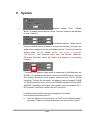
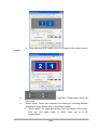
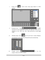
1
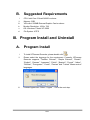
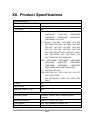
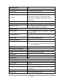
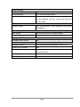
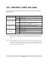
User Manual
IPCamera Recorder
1/55
Index
I.
PREFACE................................................................................................................................................ 4
II.
SYSTEM REQUIREMENTS ................................................................................................................ 4
A.
MINIMUM REQUIREMENTS ......................................................................................................................... 4
B.
SUGGESTED REQUIREMENTS ...................................................................................................................... 5
III.
PROGRAM INSTALL AND UNINSTALL.......................................................................................... 5
A.
PROGRAM INSTALL .................................................................................................................................... 5
B.
UNINSTALL ................................................................................................................................................ 8
IV.
SET UP FRONT-END DEVICE & HDD.............................................................................................. 8
A.
SET UP IP CAMERA/ VIDEO SERVER / DIGITAL VIDEO RECORDER .............................................................. 8
B.
SET UP HDD TO RECORD THE VIDEO ........................................................................................................ 14
V.
LIVE VIDEO MONITORING ............................................................................................................ 16
VI.
VIDEO PLAYBACK ............................................................................................................................ 19
A.
VIDEO PLAYBACK .................................................................................................................................... 19
B.
EXPORT VIDEO ......................................................................................................................................... 21
VII.
DIGITAL ZOOM.................................................................................................................................. 22
VIII.
E-MAP ................................................................................................................................................... 23
A.
MAP ......................................................................................................................................................... 23
B.
TREE VIEW .............................................................................................................................................. 24
C.
EVENT RECORD ....................................................................................................................................... 24
IX.
REMOTE CONTROL ......................................................................................................................... 25
A.
WEB SERVER .......................................................................................................................................... 25
B.
REMOTELITE .......................................................................................................................................... 31
X.
OTHERS ............................................................................................................................................... 33
A.
SCHEDULE RECORD SETTING .................................................................................................................... 33
B.
MOTION DETECTION ................................................................................................................................ 34
C.
PTZ SET UP AND CONTROL ....................................................................................................................... 34
D.
I/O SETUP ................................................................................................................................................. 37
E.
MOTION/ ALARM EVENT SETUP .............................................................................................................. 37
F.
SYSTEM ................................................................................................................................................... 39
G.
PASSWORD SETUP .................................................................................................................................... 45
2/55
H.
E-MAP SETTING ........................................................................................................................................ 46
I.
SYSTEM REPORT ...................................................................................................................................... 48
XI.
CONFIGURE TOOL ........................................................................................................................... 49
A.
MONITOR RESOLUTION (DEFAULT: ON) ................................................................................................... 49
B.
ENABLE/ DISABLE “WINDOW CONTROL”
C.
ENABLE/ DISABLE “PC TIME” (DEFAULT: ON).......................................................................................... 50
D.
ENABLE/ DISABLE “PING” (DEFAULT: OFF) .............................................................................................. 50
E.
ENABLE/ DISABLE “OVERLAY” (DEFAULT: ON) ........................................................................................ 50
F.
BACKUP CONFIGURATIONS ....................................................................................................................... 51
XII.
PRODUCT SPECIFICATIONS .......................................................................................................... 52
XIII.
GRAPHIC CARD TEST TABLE...................................................................................................... 55
(DEFAULT: OFF) ................................................................ 49
3/55
I. Preface
IPCamera Recorder (includes 1,4,9,16 and 36 channels) is a video recording
software which supports IP Camera, Video Server and Digital Video Recorder.
People use IPCamera Recorder to monitor the real-time video, record the video on
PC then playback the recorded video when necessary.
IPCamera Recorder supports 5 different ways to record the video, including
normal recording, schedule recording, motion-triggered recording, alarm-triggered
recording and manual recording. Moreover, E-Map and Multi-Monitor are the
build-in functions within IPCamera Recorder.
Via activating the function of web server, IPCamera Recorder provides web
browser and RemoteLite program for user demand.
II. System Requirements
A.
Minimum Requirements
i.
ii.
iii.
iv.
v.
vi.
CPU: Intel Pentium 4 2.0G
Memory: 1GB
VGA card: 128MB External Graphic Card or above
Monitor Resolution: 1024 x 768
OS: Windows 7/Windows Vista/ XP / 2000
File System: NTFS
4/55
B.
i.
ii.
iii.
iv.
v.
vi.
Suggested Requirements
CPU: Intel Core 2 Quad Q6600 or above
Memory: 2GB
VGA card: 256MB External Graphic Card or above
Monitor Resolution: 1024 x 768
OS: Windows 7/Vista/ XP/ 2000
File System: NTFS
III. Program Install and Uninstall
A.
Program Install
i.
To install IPCamera Recorder, please double click
ii.
Please select the language for the requirement. Currently, IPCamera
Recorder supports ”Tradition Chinese”, “Simple Chinese”, “Danish”,
“English”, “German”, “Japanese”, “Polish”, “Spanish”, “French”, “Italian”,
“Russian”, “Portuguese”, “Czech”, “Persian” and “Turkish” fifteen sorts of
languages.
iii.
License Agreement. Select “I Agree”,Go to the next step.
5/55
.
iv.
Select the directory for IPCamera Recorder. The default installation
directory is "C:\IPCamera Recorder". Select “Next”.
v.
Set up the name of the program folder. The default is “IPCamera
Recorder”. Click “Install” to start the installation.
6/55
vi.
When finish, click “Close” to close the procedure of the installation.
vii.
To start the program, select “Start” Æ”Program”Æ””IPCamera
Recorder ”Æ”IPCamera Recorder”. In Windows Vista/ Win7, please
right-click on the short cut icon of IPCamera Recorder or the main
program, then select “Run as administrator” to start the program.
Please refer to following example which is based on 36H IPCamera
Recorder.
viii.
ix.
Additional monitor screen might be seen if second monitor is connected.
In the IPCamera Recorder, the first and the second live-viewing screens
are similar, but the number of the channels displayed on the screen
might be different.
7/55
x.
If multi-monitor is not supported by PC, the multi-monitor mode
and the multi-monitor ON/OFF
will be inactivated.
B. Uninstall
i.
To uninstall the program, select “Start” Æ ”Program” Æ”IPCamera
Recorder”Æ”Uninstall” to remove the program.
IV. Set up front-end device & HDD
To start recording, please set up the IP camera/ Video server & HDD.
A.
Set up IP Camera/ Video Server /
Digital Video Recorder
There are 2 ways to set up the IP Camera/ Video Server
i. Configure Tool
a. Select
“Start”Æ
”Program”
Æ
”IPCamera
Recorder”
Æ ”Tools”Æ ”Configure tool”. In Windows Vista/ Win7, please
right-click on the desktop short cut or configure tool, then select
“Run as administrator” to start the program.
8/55
b.
ii.
“Configure tool” integrates “IPInstaller”. When start “Configure tool”,
it will search IP camera & video server automatically. To re-search
the device, please click “Scan IP”.
c. Select the IP camera/ video server you would like to add.
Drag-and-drop to the video channel listed above. Then type the
username & password of the device.
d. When finish the configuration, click “Save” to save all the
information.
Set up IP camera/ video server in the administration page
a.
Select
to enter IP camera/ video server set up page.
Note: The following examples are base on 36CH IPCamera
Recorder.
9/55
b.
There are 18 channels listed on the left side of the administrator
page. Users can use
to switch 1-18, 19-36 channels.
Moreover, users can use either keyboard to enter the setup values,
to activate the virtual keyboard to
or the mouse to click
configure each channel.
c.
Camera can be configured in the general setup page. First, click
to enable each channel and to set each camera.
d.
Please select channel type (Normal or Attached):
Normal: The same as the main setup page.
Attached: If user selects one channel as attached channel type,
user has to select video source. Moreover, due to the
attached channel is not physically linked to any camera;
it will not cost any bandwidth loading.
10/55
Application of attached channel: Attached channel type can
operate with the digital zoom function. User can select different
spots in the main channel and attach to different attached channels.
Because attached channel type is not physically linked to any
camera; such channel will not cost any loading of camera or HDD
space. For instance, the following figure shows that CH2, 3 and 4
are only three parts of the CH1.
e.
In the basic setting as showed below, channel name can be saved
in the “Channel Tag” to distinguish each channel. IP address is
indicating the channel. With IP Share (Router), the Port needed to
be adjusted in case of conflict. Fills in the ID and the Password for
each channel, then click
11/55
to connect each device or channel.
Click
will enable IE to browse each channel.
f.
Within the Image setup page as showed below, users can alter
image Resolution, Quality, Video Format, and Frame Rate.
g.
In the Pre & Post Alarm Recording setting page as showed below,
users can change the recording time interval.
h.
In the Information setting page as showed below,Tag / Date / Time
can be displayed on the live viewing。
i.
In the Display setting page as showed below,users can select
display mode.
12/55
When
is selected, only I-Frame will be
transferred and displayed in live-viewing; Enabling
will cause live-viewing to display the original
image size (as showed below).
j.
In the Audio setting as showed below,clicks “Enable Audio” to
enable audio recording.
k.
Before exiting administration page, remember to click
to
save all the configurations.
l.
Moreover, in advanced setup, click
to setup the tag, Date
/Time and status location of each shown channel. Click
within advanced setting can setup such as the size, format and
color of tag, Date/Time and status.
NOTE: The advanced setting will apply to all shown channels.
13/55
B.
Set up HDD to record the video
To record the video on PC, HD space is better to be set first. Or, IPCamera
Recorder will perform the record by the default setting (Based on the HD space).
i.
ii.
iii.
Start the program, enter administration page and click
button to
the disk setup page.
Before the space is set, the default setting path is the folder, Record,
which the software installed. Moreover, the default setting of available
data storage quantity is No Limitation.
If the new recording path would be added, click
new recording path. In contrast, click
button to add the
button to delete the
recording path.
button first.
iv.
To add the new recording path, click
v.
Then, use the mouse to select the path and click
complete the setting. The image is shown in the following,
1
2
3
14/55
button to
vi.
After complete the new recording path setting, click
/
(Up
and Down) to select the sequence of the recording path. While the disk
space of the priority path is full, the recorded data will be reserved in the
next path.
vii.
To mount the available space, click the data recording path first. Then,
click
/
of the “Available (MB)” to mount the space. Moreover, use
the keyboard can mount the space as well.
viii.
Finally, click
to reserve all the settings.
* NOTE:When “Keep Video Days” function is activated, the amounts of reserved
data will follow by the number that the user inserted. Please see the following
image as the reference,
15/55
V. Live Video Monitoring
i.
IPCamera Recorder supports the following real-time monitoring mode.
a.
36 Channel IPCamera Recorder can switch 36-CH
16-CH
, 9-CH
multi-monitor
, 4-CH
, 1-CH
,
, and
(16CH each).
ii.
: Enable/Disable multi-monitor.
iii.
: Full Screen mode. To exit the full screen mode, use “Esc” or
right-click the mouse.
iv.
: Minimize the program.
v.
: Auto rotating channel. Users can set switching time interval
,and determine the initial screen split value
.
vi.
: Manual recording. To start recording immediately. Moreover, to
click the button again can stop recording.
vii.
: Recorded video playback.
viii.
: Get into administration page.
16/55
ix.
: Get into E-Map
x.
: Close the program
xi.
It shows the status of each channel.
Indicate the video recording status.
Indicate Motion Detection.
Indicate Alarm status.
xii.
: PTZ controller interface. Provides
Focus、Zoom、IRIS、Auto/ Stop Patrol and Preset Point control.
xiii.
: DVR Control Panel. When
the selected channel is DVR, It will show the control panel to control
DVR, such as change split, playback and so on.
: Digital Zoom Control Panel. After selected
xiv.
the channel, the extra image zoom window will be displayed to control
the digital zoom in/out.
xv.
: I/O switch. There are up to 4 I/O controls. ( if remote device
supported)
xvi.
: Chatting switch. On/Off 2-way audio (if remote device
supported).
xvii.
: Broadcast switch. On/Off broadcast function (if remote
device supported).
17/55
xviii.
: 04CH MPEG4 DVR Playback Control Panel.
When selected channel is 04CH MPEG4 DVR module, the control panel
will reveal. Click
button can perform playback via time and event
searches as following:
18/55
VI. Video Playback
Click
to enter video playback mode.
Note: The following example is based on 36CH IPCamera Recorder.
A.
Video Playback
i.
Use calendar to select the date. As shown in the following figure, the
“day” means there are recorded data in that day. For example, there are
videos in 2007/07/20.
ii.
After selecting the date, please click
channel you would like to play (36CH version).
19/55
to select the video
IPCamera Recorder supports different kinds of playback mode.
Currently, IPCamera Recorder supports up to four channels
synchronized and asynchronized playback.
iii.
When choose the date and video channel, it will show the recording
status.
a.
b.
c.
d.
e.
iv. Click
v.
Use
No color: No video data.
Red: Normal recording data.
Yellow: Motion-triggered recording data.
Blue: Alarm-triggered recording data.
Gray: The time you choose to play.
to start playback. Click
to pause it
to fasten the speed. 1x, 2x, 4x, 8x, 16x and 32x available
(depends on the hardware and total channels).
vi. Use
to go to previous/ next frame.
vii. Check “Asynchronize Play” to enable different time and channel
playback.
viii. Check “Show tag”, “Show time” to show title & time on each channel.
ix. Check “Disable Digital Zoom” to see the original size of the video.
x. Check “Event List” to see the event records.
20/55
B.
Export Video
Video data can be export as JPG or AVI format.
A. Export as JPEG format:
i.
Click
. It will show the following dialogue box.
ii. The filename will be “channel number_yyyymmdd_hhmmss.jpg”.
B. Export as AVI format
i.
Click
. It will show the following dialogue box.
Note: The following figure is based on 36CH IPCamera Recorder.
Different version may have different layouts.
ii.
Select “start time”, “end time”, “video channel”, and the directory to save
the video. Click
to start the procedure.
iii.
To record voice, please check “including Sound”.
iv.
It exports the video into different AVI files for each channel if
multi-channel have bee selected.
21/55
VII. Digital Zoom
When enabling the digital zoom function, user can zoom in/out the image to get
proper view. Digital zoom can be functionalized in live-viewing, playback viewing,
second live-viewing and remote program. The following figures refer to the digital
zoom panel.
There are there parts of the digital zoom panel.
i.
Preview window: The image or video in the preview
window is not live, the image frame will be updated within a time interval.
The red frame indicate the live-viewing window, and the number of the
left-down corner indicate the zooming rate.
ii.
Digital zooming bar: By moving the control bar up or down, the
live-viewing and preview window will be zoomed in or out. The zoom rate is
from 100% to 1000%.
iii.
Zoom status: By un-check this function, the image or video will be
displayed in the original size.
The default of the digital zoom is enabled. User can change the default by
clicking
page. Check
in the main page and click
to enter the channel setup
to disable digital zoom control.
22/55
VIII. E-Map
Click
A.
to enter E-map.
Map
The camera icon
and alarm icon will blink when motion or sensor are
triggered. Double click the icon can see the live video if necessary.
23/55
B.
Tree View
It will show the camera list on the right hand side of E-Map page. Double click the
camera to see the live video.
C.
Event Record
All the events (motion & alarm) will be listed on the bottom of this page. Selecting
each specific event will trigger each event to playback.
24/55
IX. Remote Control
After activating the function of Web server, IPCamera Recorder provides web
server browser and RemoteLite program for user’s demand.
and activate web server
Enter the administrator page, please click
within Network setting area which is shown in the following.
A.
Web Server
Enable Web Server will allow web browser to connect to recording software
server to monitor real-time image. Please refer to instructions in the following.
i.
Connection Method: In Windows Vista/ 7, please click right click on
the IE web browser and select “Run as administrator” to start the
program. For example, within Internet Explorer 7, input the address:
ii.
).
http://192.168.1.104/ (which is seen in above image
Connection Page: After successfully connected, the user will see
the operating interface shown in the following:
Upper-Left of the connection page shows the Language options, which
includes “traditional Chinese”, “simplified Chinese” and “English” options
currently. The following are the remote monitoring options:
iii.
On-Line Monitoring: The function has to operate with “Remote AP
Server” enabled. If the OS has installed Windows XP or Windows
Vista, please perform the following internet options setting steps:
25/55
a.
Click the “Tools” Æ “Internet Options”
b.
Click “Security” Æ “Trusted sites”
c.
Click sites, then unclick the option in Step 1. Input the IP
address of the recording software server in the “Add this Web
site to the zone” area, then click “Add” button (Step 2) to
complete the trusted sites list. Finally click “OK” to exit.
26/55
2.
1.
d.
After entering “Online Monitoring”, please click “information
bar” when enter the first time. (The prompted information is
normally located under the browser).
a.
Within the pop-up drop down list, please click “Install ActiveX
Control…”.
b.
Click “Install” to perform the installation.
c.
If the installation does not work, please click “Tools” Æ “Internet
Options…” Æ “Security” tag Æ “Custom Level”
27/55
Security Settings window will pop-up, and the user has to change
the following options:
Æ Set for “Prompt”
Æ Set for “Prompt”
Æ Set for “Enable”
Æ Set for “Prompt”
After complete the setup, please repeat Step d~ Step f.
28/55
h.
After the installation, the online monitoring page will show as
following:
i.
Input the correct User Name and Password
then click
j.
to connect with the camera.
During the connection, the user can adjust the image
transmission quality.
iv.
, and
.
Remote Online Monitoring Control: Please refer the following steps
to remove Online Monitoring software.
Internet Explorer 7 and Windows Vista:
a.
Select “Tools” Æ “Internet Options…”
29/55
b.
Select “Programs” tag Æ “Manage Add_ons…”
c.
Select “Downloaded ActiveX Controls” option, and then choose
“RemoteLiteX Control”, finally click “Delete” button and “OK”.
Internet Explorer 6、Windows XP or Windows 2000:
a.
v.
Open the OS installation folder, such as “C:\Windows” or
“C:\WINNT”.
b. Open “Downloaded Program Files” folder.
c. Right-click the mouse on “RemoteLiteX Control” option and
select “remove” to delete Remote Online Monitoring Control.
Download the remote program: When select “Download remote
program” from main page, the user can download the installation
file of remote program.
30/55
B.
RemoteLite
RemoteLite is a video recording software which is different from IPCamera
Recorder. Basically, RemoteLite is designed for live-viewing only. It is not allowed
user to playback or to change any setting. The RemoteLite is not installed within
the IPCamera Recorder ; instead, it is exported from the IPCamera Recorder .
User can select up to four channels to export. In Windows Vista/ Win7, please
right-click on the RemoteLite program, then select “Run as administrator” to start
the program. Please refer to following example which is based on 36CH
IPCamera Recorder.
RemoteLite supports multi-channel, full screen, and network connection setup.
Click
to get the connection. Moreover, user can select different
transmission speed (Fast, Medium and slow). The speed of server will be the
same as RemoteLite.
31/55
Export RemoteLite:
i.
Get into administration page then click
ii.
Within “RemoteLite Application”
。
,please click
to open
RemoteLite setup page. Please refer to following figure. Currently, there
are up to 4 channels can be exported in RemoteLite program.
a.
b.
c.
Sever IP:The network location of the server.
Port:The access port of the server.
User Name:The available names are preset by main program. User
d.
should have the authority to gain the access of the main program
using RemoteLite.
Visible Channel: User can select each channel intending to export
(Up to 04 CHs). For instance, if user “only” selects 1 and 2 channels
to export, then other channels will be the private channels. The user
can also click
contrast, click
e.
to select all channels (Up to 04 CHs). In
button again to cancel all selected channels.
Note : After complete above setting, click
to save the
exported program setting. The administrator can export different
RemoteLites to match different users’ demand. Finally, do not forget
to click
to export the RemoteLite.
32/55
X. Others
A. Schedule record setting
IPCamera Recorder supports different recording mode for different channel.
.
i.
Get into administration page. Click
ii.
Select channel to set up the schedule. Select “Schedule” tag.
iii.
IPCamera Recorder supports 5 recording modes which is including
general (red), motion detection (yellow), alarm detection (blue), motion
with alarm detection (green), and no record (white).
iv. Use mouse to select time then choose what kind of recording mode to
use.
v.
Click
to make all the channels using the same recording mode.
33/55
vi.
Besides daily schedule recording, IPCamera Recorder supports specific
time recording. Determining start/end time then click
to add to
schedule. Notice: Specific time recording has higher priority than
daily schedule.
B. Motion Detection
Each channel can set up 3 areas to detect to motion.
i.
Get into administration page. Click
ii.
Select channel to set up the motion, Select “Motion” tag.
iii.
Detection Area Setting: Click area, the use mouse to draw the area to
detect motion.
Motion Sensitivity: adjust the sensitivity for each channel.
iv.
C. PTZ set up and control
IPCamera Recorder series supports remote PTZ control.
i. Get into administration page. Click
34/55
ii. Select the channel which supports PTZ, Select “PTZ ” tag.
iii. IPCamera Recorder series supports different PTZ protocols.
iv. Make sure to choose the right protocol, ID, baud rate.
v.
Detecting point preset setup: Please refer to following figure.
3.
vi.
When finish the PTZ setup, use the control panel to control the PTZ.
35/55
vii. PTZ Custom Command Group: Currently, PTZ custom command only
supports video server. This function provides the user to add or define
its own command within the provided protocol. Moreover, the user can
create a new protocol as well. Click button will reveal the following
image,
viii. Auto Patrol: Click
/
can enable/ disable auto patrol
function. Furthermore, after activating the auto patrol function, the user
could setup the duration of auto patrol.
36/55
D. I/O setup
i.
Get into administration page. Click
ii.
Select the channel which supports I/O, Select “IO” tag.
iii.
IPCamera Recorder series supports 2 types of I/O. Users can determine
delay time interval from 1 to 60 seconds.
In the live-viewing, I/O interface may have different controller depending
on each channel or remote device.
iv.
E. Motion/ Alarm Event setup
i.
Get into administration page. Click
ii.
Select the channel which supports I/O, Select “IO ” tag.
iii.
The response actions are shown in the following when motion and alarm
are triggered.
a.
E-Mail: Send the E-Mail. Please click
37/55
option first,
b.
and then click
button to complete the relevant setting.
Play Sound: Set up the time of play sound. (NOTE: 0 sec is
represented the sound is continuing until the user clicks the
triggered channel.) The user can select the sound from the buzzer
or the specific sound file by clicking
button. Moreover,
after complete the sound file setting, please click
c.
to test
the selected sound file.
Pop Up: If the selected channel is triggered, the program will
pop-up and display the triggered channel in the full screen mode.
Furthermore, the user can select the pop up time as well. (NOTE: 0
sec is represented the full screen of the triggered channel is
continuing displayed and will not back to the split screen mode.)
38/55
F. System
i.
Network setting : Click “ Enable
Server” to enable remote device control. The port needed to be adjusted
in case of conflict.
ii.
Multi-Monitor setting:Under the PC
connects Multi-Monitors (it refers to exceed two monitors), the user can
select what is displayed on the connected monitors. This function can be
worked while the PC installs graphic card which is supported
Multi-Monitors* and connects more than one monitor. Moreover,
IPCamera Recorder series will detect the quantity of connecting
monitors.
(* Normally, the graphic cards which is supported to Multi-Monitors are
D-SUB + DVI interface and has to connect one D-SUB monitor and one
DVI monitor. Moreover, some graphic cards will have DVI to D-SUB
connector. Through the connector, the graphic card can support D-SUB
+ D-SUB interface and can connect two D-SUB monitors such as ASUS
A9200SE. Nowadays, the higher level graphic card can support DVI +
DVI interface, and has to connect two DVI monitors.)
It could be performed the following setting after connected
multi-monitors and reboot the PC.
a. Click the disable monitor number (i.e. No.2 in the following image.)
and select “Extent my Windows desktop onto this monitor” option.
39/55
b.
Drag and drop the monitor icon to correspond the actual monitor
position.
iii.
Log Write:Please select which log
iv.
file to save.
Screen setup:Users can customize live-viewing by choosing different
channels to swap. Please refer to following example,
a. 36CH version: For each split window, user can setup to 16CH, 9CH,
4CH and 1CH swap mode. In 36CH, there are up to 40
combinations.
40/55
v.
Please click
to enter screen setup page (based on 36CH
version).
vi.
Keyboard Lock: Check
to enable
keyboard lock. By enabling this function, the application hotkey will be
disabled (i.e. Ctrl + ESC、Alt + Tab、WIN and Alt+F4) to avoid illegal
usage.
vii.
Windows reboot: Click
to set up the time to reboot Windows
automatically. It will re-start the IPCamera Recorder automatically.
viii.
Program
auto-run:
To
program whenever the PC is reboot.
41/55
run
the
ix.
E-mail alert: When the motion is triggered, IPCamera Recorder sends
the e-mail to some specific account.
.
d.
Get into administration page. Click
e.
Check
f.
Click
g.
E-MAIL setup page: To enable e-mail service, please fill in the name
of SMTP server. To verify the user, please check
.
to get into setup page.
,and fill in the user account and password.
Click
h.
i.
j.
to test the e-mail service.
The default value of "From” is IPCameraRecoder.
Please fill in the e-mail destination address such as
DemoTest@test.com.
“Subject” and “Content” column: The title and the reminder of a
triggered event.
42/55
k.
Check
to attach the triggered event and image to the
pre-set e-mail address.
l.
In the e-mail setup page, click
addresses to the sending list; or click
to add more e-mail
to delete from the
sending list.
Attention: The E-mail server will not send the e-mail and the
attachment if the check box of the sending list is
unchecked.
x.
Auto Logout:Check
,the system will automatically logout
within the pre-set time
xi.
event detected.
HDD setup:
a. IPCamera Recorder series will overwrite the old data when the
HDD is full. Click
b.
xii.
,if there is no keyboard or mouse
to enable/ disable this function.
The default configuration of this function is
enable.
Date Format:
43/55
xiii.
a. There are 5 different date formats available
b. Please save the changes before exiting.
Product Information:
a.
Click
to show product information.
44/55
.
G. Password Setup
IPCamera Recorder supports simple security control.
to
get
into
password
setup
page.
i.
Click
ii.
On the right side of the password setup page, please fill in the user
name, password and select the group. Click
iii.
to add new user
and click
to delete.
After configuration, please leave the password setup page. In the
live-viewing page please click
45/55
to login/logout.
H. E-map setting
Get into administration page. Click
to set up the E-map.
i.
Right-click the mouse to set up and add the map.
ii.
Drag and drop the icon (
) to put the camera & sensor on the
map.
46/55
Please right-click
iii.
to setup
the
camera.
Event save time setting : On the right side of the setting page
, please determine recording time of the motion
or alarm events. There are up to 5000 events can be reserved. The
iv.
previous records will be over-write if exceeding 5000 records.
Auto Enter Playback Mode : By enabling this function
, when the motion and the alarm events are
triggered, the system will automatically playback the event (E-MAP
mode only).
v.
Click
to save the configuration.
47/55
I. System Report
Get into administration page and press
button to enter “Report” page.
When the IVA camera is connected into the software, the software will reload the
detection result of “People Counting” item. The counting history report helps user
to manage and understand trends and patterns that affect the everyday operation
information.
1
2
3
User has to be selected the CH first which connected to IVA camera, and then
click the date to view the counting information. Moreover, the user can select the
bar chart information as well. (i.e. In, Out or Both )
The user could be reserved the format of revealed bar chart information. The
Excel and CSV data format are supported recently.
48/55
XI. Configure Tool
A. Monitor resolution (Default: On)
The program resolution of IPCamera Recorder is 1024 x 768. It will change the
monitor resolution to 1024x768 if the monitor resolution is not 1024x768.
i、 Run Configure tool
ii、 “System” tab
iii、 Select ”Auto Adjust Resolution” to adjust the resolution automatically.
B. Enable/ Disable “Window Control”
(default: off)
This function is only available for resolution larger than 1024 x 768 monitor. This
function can not combine with “Auto Adjust Resolution”. When this function is
enabled, if monitor resolution is over 1024 x 768, user is allowed to drag the
window to proper position.
49/55
C.
Enable/ Disable “PC Time”
(default: on)
By enabling this function, system will record the video transferring time based on
the PC.
Note: By disabling this function, the recording time of the remote devices
may different from the PC time.
D.
Enable/ Disable “Ping”
(default: off)
Some network device will disable the “ping” function. To connect IP camera/
video server which are protected by the firewall, please disable this function to
make sure it can connect correctly.
E.
Enable/ Disable “Overlay”
(default: on)
Disable the overlay function if the graphic cards don’t support this function.
Note: Enabling overlay function can reduce CPU loading and enhance PC
performance.
50/55
F.
Backup configurations
Use Configure tool to back up all the configurations. It will be very useful to
maintain the software using these configurations.
i、 Select the back up path. Click “Export”.
ii、 To import the configurations into IPCamera Recorder, select the backup
folder, click “Import”.
51/55
XII. Product Specifications
Video Monitoring
Channel
36
Real-Time Monitoring Mode
1, 4, 9, 16, 36
Full Screen
Yes
Supported Hardware Device
Video
Server:
HWS-01HP,
HWS-01HE,
HWS-01HD,
HVT-01HT,
HWS-04HD
HWS-04HD, HWS-01AD, HWS-02AD,
HWS-04AD, HVT-01AT
IP Camera: HLC-36F, HLC-36M, HLC-36P,
HLC-42M, HLC-42P, HLC-49M, HLC-49P,
HLC-82F, HLC-810, HLC-82F, HLC-830,
HLC-1CI, HLC-840, HLC-105, HLC-79G,
HLC-49C/G/S,HLC-81AG/ AD, HLC-1NAG/
AD, HLV-1WAG/ AD, HLC-79AG/ AD,
HLC-7RAG/ AD, HLC-84AV/ AM
DVR: HDR-04MD, HDR-04MN, HDR-04MP,
HDR-04NP,
HDR-04FE,
HDR-04DE,
HDR-08MN,
HDR-09MP,
HDR-09RE,
HDR-16MN, HDR-16MP, HDR-16NE
PT: HLC-860, HLC-870
AXIS: 205, 206, 207, 210, 211A, 213, 214, 221,
225, 231D, 232D,
241 (4Ch Server), 2100, 2110, 2120, 2130,
2420
E-map
Yes
Multi-Monitor
Yes
Attached Channel Type
Yes
Channel Setup
Recording Mode
Schedule, Motion, Alarm, Motion & Alarm,
Manual
Record Resolutions
SXGA, D1, VGA, CIF, QCIF
Video Quality
best, high, standard, medium, low
Show Title and Time
Yes
52/55
Recording Audio
Yes
Monition Detection
Yes
PTZ Control
Yes, via PTZ control panel
DVR Control
Yes, via DVR control panel
IO Control
Yes, can activate preset alarm devices
such as siren or alarm, It supports on&off
switch mode and delay switch mode, up to 4
I/O Control
Digital Zoom
Yes, via digital zoom control panel
Two-way Audio
Yes
Advanced Setup
Yes. Setup Tag, Time/Date and Status location of
shown channel and the font setting
System Setup
Multi-Screen
Yes, Live-viewing, Multi-Live Window,
Window, E-MAP
Playback
Log Management
Yes, system log, alarm event, motion event, user
log.
Date Format
Yes, 5 Data formats setting
Product Information
Yes
Display Setup
Yes
36CH:1,4,9 and 16CH split window setup(Up to
40 combination)
Keyboard Lock
Yes
Auto Reboot by Schedule
Yes
Auto Startup
Yes
E-mail
Yes, motion and alarm trigged
Auto Logout
Yes
HDD Overwrite
Yes
Alarm Sound
Yes
Video Playback
Video Search
Yes, time search
Video Export
JPG, AVI
Print Image
Yes
Video Forward/ Backward
1x, 2x, 4x, 8x, 16x, 32x(depending on hardware
or channel)
Video Simultaneous Playback
Yes, up to 4 channels
Digital Zoom
Yes, by digital panel control
53/55
Event Warning
On Screen Display
Yes
E-mail Warning
Yes, with event attachment
Alarm Output
when motion detected, pre-selected alarm sound
will be playback and live screen will enter full
screen mode
Security
Security Setup
Yes, user account, user password and group
management
Remote Control
Web Server
Remote Connection via Web Browser
Remote Program Server
Remote Connection via RemoteLite Program
Configure Tool
Hardware Auto Search
Yes
Auto Resolution Adjustment
Yes, Best resolution is 1024 x 768
Window Control
Yes, Resolution must be larger 1024 x 768
Enable Ping Function
Yes
Time Synchronization
Yes, system will record the video transferring time
based on the PC.
Use Overlay
Yes
Backup Import/ Export
Yes
54/55
XIII. GRAPHIC CARD Test Table
The following list presents the graphic cards which have been tested with IPCamera
Recorder series.
OS
Windows 2000
ATI
NVIDIA GEFORCE 6200
ATI
RADEON 9200, RADEON 9550, RADEON XPRESS 200,
RADEON HD 3650
NVIDIA
GEFORCE 6200, GEFORCE 6600, GEFORCE 7100,
GEFORCE 7300, GEFORCE 8500
ATI
RADEON XPRESS 200M, RADEON HD 2400 PRO
Windows XP
Windows Vista
Windows 7
RADEON 7500
NVIDIA GEFORCE 8500
Intel
G33
ATI
RADEON HD3650
NVIDIA
GEFORCE 7050
INTEL
G33/G31
NOTE 1: All the graphic cards which are shown in above table have to update their driver to
the latest version. Please go to ATI, NVIDIA or Intel official website to update the
driver.
NOTE 2: By using Windows Vista, due to Intel G33 Driver (Version: 7.14.10.1461) from its
OEM have not supported Vista DirectX 10 yet, it cannot display the image within
Overlay mode while operating Dual-Monitor. Therefore, this caused problem still
wait for the solution from its OEM.
55/55