1
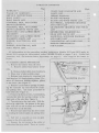
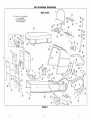
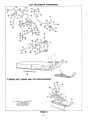
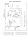
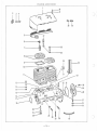
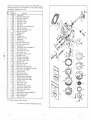
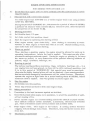
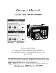
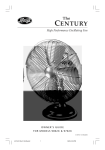
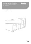
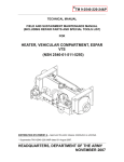
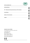
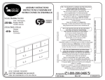
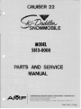
CRUISER 2 2
MODEL
5813·0000
PARTS AND SERVICE
MANUAL
~F
AMERICAN MACHINE & FDUNDRY CDMPANY
CONSUMER PRODUCT S SALES DIVISION
PARTS & SERVICE DEPARTMENT
Whiteford Road, York, Pennsylvania 17402· Area Code 717 848-1177
PART NO. 37950
TABLE OF CONTENTS
Page
WARRAN TY. . . . . . . . . . . . . . . . . . . . .. 1
TABLE OF CONTENTS . . . . . . . . . . . 2
SER VICE INSTR UCTIONS .•..•..... 2
BODY PAR TS . . . . . . . . . . . . . . . . . . . . 4
BODY PARTS LIST . . . . . . . . . . . . . . . . 5
STEERING, SKIS, AND UPPER
DRIVE ELEMENTS . . . . . . . . . . . . . . . . 6
STEERING, SKIS, AND UPPER
DRIVE ELEMENTS PAR TS LIST. . .. 7
DRIVE BELT AND LOWER DRIVE
ELEMENTS. " . . . . . . . . . . . • . . . . . . . 8
DRIVE BELT AND LOWER DRIVE
ELEMENTS PARTS LIST .•..•..... 9
ENGINE, ELECTRICAL, AND
FUEL . . . . . . • . . . . . . . . • . . . . . . . • . . . . 10
ENGINE, ELECTRICAL, AND
FUEL PAR TS LIST . . . . . . . . . . . . . . . . II
Page
CHAIN CASE COMPLETE AND
PAR TS LIST . . . . . . . . . . . . . . . . . . . . . . 12
WIRING DIAGRAM . . . . . . . . . . . . . . . . 13
BLOCK AND HOOD . . . . . . . . . . . . . . . 14
BLOCK AND HOOD PARTS LIST .... 15
FLY WHEEL, MAGNETO DIAGRAM
AND PARTS LIST . . . . . . . . . . . . . . . . . . 16
CRANKSHAFT DIAGRAM AND PAR TS
LIST . . . . . . . . . . . . . . . . . . . . . . . . . . . . 17
GENERATOR, SOLENOID DIAGRAM AND PARTS LIST ..•.•..... 18
MANIFOLD, MUFFLER DIAGRAM
AND PARTS LIST .•..•.•••..•....•. 19
CARB URETOR AND PAR TS LIST. .. 20
ENGINE OPERATING IN STRUCTIONS ..••.•.•.••..•...••.• 21
All information in the preceding section relative to Models 5811 and 5812 apply to
Model 5813 except the information under POWER TRAIN on pages 7 & 8, "Brake Adjustment" and "To Remove Drive Sprockets" on page 11. New copy for t he latter is
below.
TOR E MOVE DRIVE SPR OCKETS
1. Remove the battery from the sled.
A . Re move cables from battery terminals.
B. Remove battery hold-dow n fasteners.
2. Place rear of sled on kick-stand.
3. Release track tension by removing both
right hand and left hand adjuster plates. R emove all fasteners holding adjuster plates
to the frame (See Figure 1) .
4. Remove track tension springs by pushing the extended top end toward the center
and pulling down. Use same procedure on
both sides (See Figure 2) .
5. Remove the three screw s, lock washers,
1.nd nuts that hold the bearing retainer to the
right side of the sled (See Figure 3) .
6 . Turn sled up on its right side. With the
sle d on its right side, the grease in the gear
case will not run out as much as it would if
the sle d were on its left side.
7 . R emove lacer pins from the drive track
by bending the ends s traight a nd pulling them
ou t.
8 . Pull belt to one side s a you can gain
ac ces s to the drive sprockets .
9. Remove the set s crew in the collar at
both ends of the drive shaft. There is a notch
FASTENERS
ADJUSTER PLATE
Figure 1
Figure 2
- 2-
BOLT AND WASHER
•
c
DRIVE SPR OCKETS
COLLAR
SET SCREW
BEARING RETAINER
Figure 3
in each collar. Insert a punch into the notch.
Tap the punch lightly to loosen the collar
(See Figure 3).
10. Remove the three screws which secure
the chain case cover (See Figure 3).
11. Remove the bolt and washer from the
end of the drive shaft (See Figure 4). Tap
on the drive sprockets with a hammer. Tap
them to the right side. This will free the
drive shaft from the gear shaft.
12. Loosen set screws which hold the drive
sprockets in place. Slide them off the left end
of the drive shaft.
13. Replace or repair sprockets.
14. Reassemble in opposite order.
15. When replacing the drive shaft into the
gear case, align the large sprocket and the
spacer behind it with your finger before inserting the drive shaft (See Figure 5). Insert
shaft and align notches on the end of the drive
shaft with those on the sprocket in the gear
case.
Figure 4
Figure 5
-3 -
AMF SKI-DADDLER SNOWMOBILE
BODY PARTS
For Parts List -
22
See Page 5
ALL UNNUMBERED
PARTS INTER·CHANGEABLE
WITH OPPOS ITE SIDE
~d
~~~
88
"","""
~/ I
72 52 /J.J
5t l- J
2~ ~ ~"'-29' !
~ ~
49
41
l-'-'
37
45
I
IF>
44
/
~ 'lila
. Vl)
m...
If"00 _
\)=
46'a
40 43
-
0
\42
eJ
39 38
\)=
I-
d~
I
/
;:1.
29
IOr:e
.l>-
~
G;
12
»
~.
--13
••
•
.;:.;: Q
i
2
1":--.
54I
-
o
26~"It-10
~-64
48
"
II
..
II
I»m>
B-.
(D..~
I -.
19 17
26 - ~
'l
15
~~.
ry.
18~
o
-----
~~
57
~1~"'-t
62 ._____<P' -A-· , ---------- 66
•
84
J 'I'§)
~
~
83- 1'9>
'"
., "'"
)2 81
63
~~~ITY6
~~- .
O~"
60
65
~
18
-
~
~69
l-
51
0
0'61
1)=,8
~22
-30
~OI J~ ~64
31
J
68
'~o ~9
860
11
~~
35
28
~
I
3~
34
tiS
u
•
AMF SKI-DADDLER SNOWMOBILE
ALWAYS GIVE THE FOLLOWING INFORMATION WHEN ORDERING REPAIR PARTS:
•
..
c
l. THE PART NUMBER
2. THE PART NAME
3. QUANTITY DESIRED
4. THE MODEL NUMBER-58130000
SEND PART ORDERS TO ATTENTION OF: PARTS DEPARTMENT, P. O. BOX 377, DES MOINES, IOWA 50302
Your Unit is Right Hand (R.H.) or Left Hand (L.H.) as you stand behind it.
DO NOT USE KEY NUMBERS WHEN ORDERING REPAIR PARTS, ALWAYS USE PART NUMBERS.
BODY PARTS
FIGURE 1 PARTS LIST FOR MODEL 58130000
Key
No.
Port No.
1
2
3
4
5
6
7
8
9
10
11
12
13
14
15
16
17
18
19
20
21
22
23
24
25
26
27
28
29
30
31
32
33
34
35
36
37
38
39
40
41
42
43
44
304 18
30295
30555
30529
30376
30377
30394
30395
30396
30397
30398
30399
30233
30245
30246
2251
8728
121913
121926
941 7373
11 2726
125680
120854
30275
457509
94 133 14
120691
995355
30276
30400
30409
30412
30268
30624
30269
30414
29080
29081
29266
30363
31151
30362
120622
132764
Description
Windshield
Rubber Spacer
Rubber Bumper Strip
Alu mi num Trim Strip
End Cap Trim- R.H.
End Cap Trim-L.H .
Kick Stand Tube
Hand Rail Tube
Hood Access Lid
Tote Pouch
Seat Back
Seat
Snap-Male Half
Spri ng-Latch Hoo k
Latch Hook
7/ 32" x 3/4" Washer
Formed Washer
* 1/4" -20 X 11/4" Hex Hd. Sc.
* 1/4" -20 X 11/2 II Hex Hd. Sc.
*No. lOx % II Flat Washer
* 1/16" x 1f2" Cotter Pin
* 1/4 II - 20 x % II Truss Hd. Mach. Sc.
* 1/4II -20 x %" Hex Hd. Sc.
3/16" x % II Pop Rivet
No. 10-24 Lock Nut
1/4" -20 Lock Nut
No. 10-24 x 1 % II Flat Hd. Sc.
1/4" -20 x 1" Truss Hd. Sc.
1fs II Pop Rivet
Fuel Inlet Tube Assy.
Seat Back Tube Assy .
Fuel Ta nk Reta iner Plate Assy.
Gas Cap
Chain
Fue l Level Indicator
Main Frame Assy.
Ta i l Lamp Door
Tail Lamp Lens
Rubber Spacer
Ta il Lamp
Seat Back Cover
Tail Lamp Grou nd Wire
*No. 8-32 Hex Nut
*No. 8-32 x % II Rd . Hd. Mach Sc.
Key
No.
Part No.
45
46
47
48
49
50
51
52
53
54
55
56
57
58
59
60
61
62
63
64
65
66
67
68
69
70
71
72
73
74
75
76
77
78
79
80
81
82
83
84
85
86
87
88
134186
271482
30581
30218
30630
16615
134244
996907
4575 14
30283
30219
16634
30417
31450
30229
30263
30264
30265
30270
24180
30278
30279
120706
308 10
31763
30365
30488
132911
30635
30605
30272
30171
122007
9415988
122027
30633
22780
120272
996407
271184
30587
30285
16439
30631
*No. 6 -32 x 1" Ova l Hd. Sc.
No. 6-32 Lock N ut
Glove Box Lid
Head Lamp Assy.
Windshie ld Trim Stri p R.H .
Light Switch Deca l
*N o. 8 -32 x 11/4 II Ova l Hd. Sc.
*No. 10-32 Keps Nut
*No. 8-32 Lock Nut
Sponge Pad
Latch
Ign ition Decal
Hood
Fue l Tank
Gas Line--Long
Gas Tank Inlet Fitting
Gas Tank Outlet Fitting
Fue l Fi lter
Fuel Pick-Up Tube
Hose Clamp
"O"Ring 11/2" O.D.
" 0" Ring 1 1/4 II O.D.
*%" -20 x 1/2" Hex Hd. Sc.
Hood Grommet
Rubber Strip
Support Ang le
Hose Clamp
*N.o. 10-32 x %" Rd. Hd . Sc.
Clutch Guard
Plastic Hood Trim
Hinge
J- Bolt
*5/16" - 18 x %" Hex Hd. Sc.
*5/ 16"-18 Lock Nut
*5/16"- 18 x 11/4" Hex Hd. Sc.
Bumper
5/ 16"- 18 Curved Hd. Bolt
5/1 6"- 18 x 1" Truss Hd. Sc.
*5/1 6" Wa sher
*5/ 16"-18 Lock Nut
Rear Brake Mounting Bracket
Plate (Glove Box Lid)
Decal F.N.R.
Windshield Trim Tape L.H.
For Illustration See Page 4
*Standard Hardware Items may be purchased loca lly.
c
Description
All replacement parts will be supplied in cu rrent production co lors or in a neutral co lor.
-
5-
AMF SKI-DADDLER SNOWMOBILE
55-,
36
56
1Pr/
~18
~ -47
32
37
e
26 /
43
48
COl
41
&>,,43
\ .....-49
ru
6i--r' ~43
69
~"t>,
35
20
J
/
/' \
\
\\ <
'",-
o
\
'
)
0
\
62
\~~~
STEERING, SKIS, FRAME AND TOP DRIVE ELEMENTS
'.
\
60
1
)9
'3
~ ..
46
~.
~
12
~JJ
4)3~10 1
8
9
For Parts List -
~~/4
~~Iq
13- : ... 19
~
2
See Page 7
oa
~-
ALL UNNUMBERED
PARTS INTER-CHANGEABLE
WITH OPPOSITE SIDE
)
FIGURE 2
- 6-
AMF SKI-DADDLER SNOWMOBILE
c
STEERING, SKIS, FRAME AND TOP DRIVE ELEMENTS
FIGURE 2 PARTS LIST FOR MODEL 58130000
c
Key
No.
Part No.
1
2
3
4
5
6
7
8
9
10
11
12
13
14
15
16
17
18
19
20
21
22
23
24
25
26
27
28
29
30
31
32
33
34
35
36
37
30247
8441
28762
137185
997314
30369
28764
28766
28770
29645
28769
995365
995224
30799
706
21777
28416
28907
121222
30673
2347
30117
120233
30149
120382
20202
24054
302 11
30212
30224
30251
27128
120396
30282
120854
29032
30284
Description
Bumper Pad
Spring Roller
Spring Pivot Pin
* Va" X 1" Cotter Pin
1/4 "-20 Centerlo ck Nut
Ski Wear Rod Assy.
Spring Plate
Leaf Spring
Main Leaf Spring
Middle Leaf Spring
Spring Mounting Bracket
% "-24 x 11/4/1 Hex Hd. Sc.
%" - 24 Slotted Nut
Ski and Wear Rod Assy.
Grea'se Fitting
Spacer Bushing
Hand Grip
Hand Control Assy.
*3/32" x %" Cotter Key
Bra ke Sp ring Bracket
Spring
Spind le Bolt
*%/1 - 16 xl/1 Hex Hd. Sc.
Spring (Spindle)
* '%" Lock Washer
Throttle Contro l Cable
"U" Strap
Column Support Plate (Upper)
Thumb Lever (Throttle Control)
Brake Cable
Spacer Bushing
Cab le Clamp
*%/1 Washer
Housing (Brake Cable)
*%/1_20 x %/1 Hex Hd. Sc.
Cable Ferrule
Cable Housing
Key
No.
Part No.
38
39
40
41
42
43
44
45
46
47
48
49
50
51
52
53
54
55
56
57
58
59
60
61
62
63
64
65
66
67
68
69
70
71
72
73
120383
457507
30575
25188
121893
124925
142443
181643
995364
999101
9413314
995339
30414
30579
181 652
9415 106
181650
424339
120614
30060
30403
30081
30124
180079
30228
30561
30535
30576
8103
30592
30392
28783
28784
30390
120638
31406
* Standard Hardware Items May Be Purchased Locally
Description
*Lock Washer
*No. 10-32 Lock Nut
Square Key
Swivel Button
* 1/4 "-20 x 7Ja" Hex Hd. Sc.
*%" -24 Jam Nut
No. 10 -32 x 1 %" Rd. Hd . Sc.
*%/1-24 x 1 1/2 " Hex Hd. Sc.
%"-24 x 2%" Hex Hd. Sc.
*No. 10-32 x %" Self Tap. Sc.
* 1/4 " -20 Lock Nut
No. 8-32 x %" Socket Hd. Sc.
Main Frame Assy.
Steering Handle & Column Assy.
% "-24 x 3" Hex Hd . Sc.
* %" -30 Lock Nut
% /1 -24 X 2 1/2 " Hex Hd. Sc.
*No. 10-32 x 1" Rd. Hd . Sc.
*No. 10-32 Hex Nut
Spindle Arm
Tie Rod
Rod End Bearing
Spindle Tube Assy.
5/16/1-18 x 1" Hex Hd. Sc.
Foot Pad
Drag Link
No. 706 Hi - Pro Key
Washer (Disc Brake)
Flat Washer
Front Brake Mounting Bracket
Driven Clutch
Disc Brake
Disc Brake Hub
Apex Gear Case Complete
*5/16/1 Lock Washer
Lever Assy.
For Illustration See Page 6
All replacement parts will be supplied in cu rrent production colors or in a neutral color.
-7-
AMF SKI-DADDLER SNOWMOBILE
DRIVE BELT AND LOWER DRIVE ELEMENTS
21
\
27
\
-ru26
15
~
29
24
~
\
_:n ~:((\,
()'"".
-Q\
25
15
XJ·~·
'
5
ff
'
~)6 3\ ~~IV
~I --9)~ -~~- ~
10 13.~
(Xl
I
4
22
8
-
____ ~GII$ -- -----
""
_.'::>
"'-
18
-r\ -i_~-®l·(28
f ~ ~~35
37
34
'-...
~
'-...
'-...
'-.....
31
12 11
'-...
45~"'-'-,-
39
24
33 26
/@~
~ 1
'V' 0
'q ~L\),
...0
51
15
42
~ @,\
@
~
~
Q
36
(
4
49
49
41
43
For Parts List -
See Pa ge 9
A LL UNNUMBE RED
PARTS INTER-CHANGEABLE
W ITH OPPOSI TE SIDE
50
FIGURE 3
.
u
14
n
•
n
()
AMF SKI-DADDLER SNOWMOBILE
DRIVE BELT AND LOWER DRIVE ELEMENTS
FIGURE 3 PARTS LIST FOR MODEL 581 30 00 0
-0
I
Key
No.
Part No.
1
2
3
4
5
6
7
8
9
10
11
12
13
14
15
16
17
18
19
20
21
22
23
706
2483
29956
29975
30464
30463
30145
28776
122007
122065
138485
181595
456145
30620
94 15988
29980
29981
29984
29985
30017
30100
30621
30085
24
25
29945
30079
Description
Grease Fitting
Spring Washer
Spacer
Ad justing Block
Rear To rsfon Spring R.H.
Rear Torsion Spring L.H.
Retainer Spring
5/ 16"- 18 x 3" Hex Hd. Sc.
*5/16"-18 x %" Hex Hd. Sc.
*5/ 16"- 18 x 2" Hex Hd. Sc.
*5/ 16" Lock Washer
*5/16"-24 x %" Hex Hd. Sc.
5/16" Washer
Short Hinge Wire
*5/16"- 18 Lock Nut
Belt Ad just. Angle Assy. R.H.
Belt Adjust. Angle Assy. L.H.
Rear Support Arm Assy . R.H.
Rear Support Arm Asy. L.H.
No. 40 Sprocket-26 Tooth
Traction Belt Assy.
Long Hinge Wire
Rear Sprocket Comp lete Consists
of (24 -25-26-27 -28-29-38)
Not Ill us.
Rubber Sprocket-9 Tooth
Grease Seal
- --- -
* Standard Hardware Items May Be Purchased Locally
Key
No.
Part No.
26
27
28
29
30
31
32
33
34
35
36
37
38
39
40
30080
120222
997316
29955
30087
30402
29944
29942
29954
29953
30560
12022 1
31802
31803
30577
41
42
43
44
45
46
47
48
49
50
51
998010
120638
30523
30524
998503
12 1887
9413314
31073
31074
31075
8288
Oescri ption
Ball Beari ng
*No. 10-24 x %" Mach. Sc.
No. 10-24 Lock Nut
Sprocket Support Plate Assy .
Bogg ie Wheel & Support Assy.
Boggie Wheel & Support Shaft
Bogg ie Wheel Spr ing
Boggie Tire
Bogg ie W heel Half (Outer)
Boggie W hee l Ha lf (Inner)
Bearing Back Up Plate
*No. 10- 24 x %" Mach. Sc.
Rear Shaft Assy. W/ Plugs
Bogg ie Support Assy. W/ Plugs
Drive Sprocket Assy . Consists of
(24-~7-28-43-44 - 45-46-47 )
-
5/ 16"-18 x %" Carriage Bolt
*5/ 16" Split Lock Washer
Plate
Hub
5/ 16"- 18 x 5/ 16" Set Sc.
* 1/4"-20 x %" Hex Hd. Sc.
* 1/4" -20 Lock Nut
Link Belt Bearing
Link Belt Collar
Link Belt Stamping
Snap Ring
-- -- --
For Ill ustration See Page 8
All rep lacement pa rts wi ll be supplied in cu rrent production colors or in a neutra l co lo r.
AMF SKI-DADDLER SNOWMOBILE
ENGINE, ELECTRICAL AND FUEL ELEMENTS
•
11
~12
.
48
31
~
~9-\1 00 33
46
g \,
,,"
a
39~~
40~
•
35-W
36--®
~
.....
~12
-46
EJ-27
Fo r Parts List -
LJ-26
~28
10
~
35~
9
18
~
See Page 11
ALL UNNUMBERED
PARTS INTER-CHANGEABLE
WITH OPPOSITE SIDE
38
~
~@-.
4
34
37
~~
46_ r
32
9
43
~44
41
I
30
25
5"e
o-~
51--
6
20
- 16
~1~
-~i\
l-47
o
6
FIGURE 4
-10 -
AMF SKI-DADDLER SNOWMOBILE
ENGINE, ELECTRICAL AND FUEL ELEMENTS
FIGURE 4 PARTS LIST FOR MODEL 58130000
Key
No.
Port No.
1
2
3
4
5
6
7
8
9
10
11
12
13
14
15
16
17
18
19
30556
29677
30557
30393
9416107
999701
999101
3039 1
26032
29073
306 18
30389
30612
30614
30615
30616
30617
135629
31470
20
21
22
23
24
25
3324
30572
9415106
446363
30568
30613
Descriptio n
Rubber Engine M ounting Pad
Connector
Exhaust Pipe
Variable Speed Belt
* % " - 16 Lock Nut
%"-20 x %" Hex Hd. Self Tap Sc.
*No. 10-32 x %" Self Tap Sc.
Drive Clutch
Key Switch
Light Switch
Wiring Harness
Wiring Clip
Lead Wire (Battery to Sol eno id)
Lead Wire (Regulator to Grou-nd)
Lead Wire (Regulator to Gen.)
Lead Wire (Solenoid to Regulator)
Lead Wire (Regular to Generator)
* 1/2 " Shakeproof Washer
Voltage Regulator (See
Engine Manual)
Solenoid
Engine Base Assy.
* %" -24 Lock Nut
*%" Washer
Engine Mount Plate
Lead Wire (Battery to Ground)
* Standard Hardware Items May Be Purchased Loca lly
Key
No.
Pa rt No.
26
27
28
29
30
31
32
33
34
35
36
37
38
39
40
41
42
43
44
45
46
47
48
49
50
51
30176
30178
30180
30375
16635
30603
30610
30628
2 1970
30676
30629
30573
30574
119117
30642
30601
30602
126177
120386
Engine
120380
180124
30489
120382
995246
124829
Description
Air Cleaner Screen
Air Cleaner Cover
Air Cleaner Mount Plate
Air Cleaner Stud
Kill Button Decal
Anchor Bracket (Throttl e Cable)
Clutch Spacer
Carburetor (Till otson HR- 3A)
Washer
Intake Manifold Ga'sket
In su lator Block
Special Screw
1/4 " Square Key
*3/32 x %" Cotter Pin
Carbureto r Adapter Arm Assy.
Battery Hold Down Assy.
Battery Hold Down Rod
1/4"-20 Wing Nut
1/4" Washer
See Footnote Below
1/4" Lock Wa'sher
%" - 16 x 11/4" Hex Hd . Sc.
Hose Clamp (Carburetor)
* %" Split Lock Wa sher
1/4"-20 Acorn Nut
%" - 16 Jam Nut
For Illustration See Page 10
All prices subject to change without notice.
All repla cement parts will be supplied in current production colors or in a neutral color.
(
Replacement engines and parts are obtainable from the Eng ine Manufacturer' s authorized Service Stations who
are also to be contacted in regards to the Engine Wa rranty. See your Engine Manual for location of these stations.
-11 -
AMF SKI-DADDLER SNOWMOBILE
CHAIN CASE COMPLETE
For Parts List See Below
FIGURE 5
CHAIN CASE COMPLETE
FIGURE 5 PARTS LIST FOR MODEL 58130000
Key
No.
1
2
3
4
5
6
7
8
9
10
11
12
13
14
15
16
17
18
19
20
21
22
23
24
*
Part No.
31814
31815
31816
31817
3 1818
31819
31820
31821
31822
31823
3 1824
31825
31826
31827
31828
31829
31830
31831
31832
31833
31834
31835
31836
31837
Key
No.
Description
Housing
Drive Sprocket & Bushing
Shifter Shaft
Reverse Pinion
Reverse Shaft
Reverse Gear
Taper Bearing Bushing
Shift Lever
Sprocket-. Driven
Input Shaft
Output Shaft
Inspection Cover
Cover Plate
Fulcrum & Nut
Washer -Axle
Gasket for Inspection Cover
Gasket for Cover Plate
"0" Ring for Flang et
Gasket for Flanget
Shaft & Bearing
Roller
Spacer-Output
Collar-Input
Timken Bearing
25
26
27
28
29
30
31
32
33
34
35
36
37
38
39
40
41
42
43
44
45
46
47
Standard Hardware Items May Be Purchased Locally
Part No.
31838
31839
31840
3184 1
31842
31843
31844
3 1845
31846
31847
31848
31849
31850
31851
31852
31853
31854
3 1855
31856
31857
31858
31859
31860
Descripti on
Spring fo r Detent
5/16" Nut
Snap Ring
Snap Ring
Seal- Input Shaft
Dust Cap
Expansion Plug
Torrington Bearing
Seal
Oilite Bea ring
Set Screw
1/8" x 1" Roll Pin
Breather
Stud
Lever Ball
Chain (by li nk)
Bearing & Collar
Flanget
Detent Ball
5/16/1 Lock Washer
%" Bolt
1/8" x 1f2" Roll Pin
1/4" Bolt
,
For Illustration See Above
All replacement pa rts will be supplied in cu rrent production colors or in a neutral color.
-12-
,
T
REPAIRMAN'S REFERENCE WIRING DIAGRAM
~
Z
o
w
U
~
w
!!?
w
1I01Vln9311 39"1101\
'"~
'"
'"Z
'"«
:I:
o
o
o
:I:
:z:
u
....
~
'"
....
:I:
:I:
g
u
....
~
Z
)
o
liE
;::
~
c
The wIring diagram shown here is a technical explanation of the circuitry on this unit. It is intended for
use by repairman or owners capable of readin g and
using wiring diagrams.
The various component parts have been labeled. See
your Serv ice Dealer for part numbers, price and o rdering
-
information. A lso see your Service Dealer for ava ilable
Service Manual.
We recommend that unless you are fully qualified
to make repairs on the electr.i cal system on this unit,
you take it to a competent repairman for such work or
adjustments.
13-
BLOCK AND HOOD
~- 38
--=----41
~ll
i'39
5
6
7
40
37
lIi
t~
36
35
8
9
34
10
12--13-- -
28
a----27
~--13
- - -14
y
18
-
14 -
)
BLOCK AND HOOD PAR TS LIST
ENGINE TYPE 2054-SRB x 18 (AMF)
C
ITEM
4
(
NOS.
QUANTITIES
DESIGNATION
549x398
Cover for air shroud
EAZI02B
Connection clamp for grounding wire
884x7
Insula tin g washe r
DIN84 - 5S M3xl5
Screw for connection clamp
549x399
Shield for cylinder
836x43
Terminal for ignition cable
SOx39
Spark plug BOSCH M 225 - T
1712x142
Cylinder head
759xl81
Gasket for Cylinder head
10
205xl78
Cylinder
II
759x183
Gasket for cylinde r base
12
DIN931 - 5S M8x65
Screw for c rank case
13
DINI37 A8
Lockwasher
14
DIN934- 5S M8
Nut for crankcase
15
DIN835 - 5S MIOx22
Stud for cylinder
16
9244x159
Crankcase assembly
17
343x135
Roll pin
18
318x340
Impulse tub e
19
7 3x2 1S
"0" ring seal for crankcase
20
DIN8 35-5S MIOx70
Stud for crankcase
21
DINI37 AIO
10
Lockwash e r
22
DIN934 - 5S MIO
10
Nut for c rank case and cylinder
23
DIN7603 A8xll, 5
Washer for drainage plug
24
DIN933- 5D M8xl58SZ
Plug for c r ankcase drainage
25
954x87
26
22Zx366
4
Straight fittin g for fuel pump
27
DIN93 1- 5S M8x60
Screw for crankcase
Stud for mounting crankcase
28
582x33
29
DINI37 A8
Main bearing plate fly wheel end
30
DIN931-5D M8x20
Screw for main bearing plate
31
73x219
110" ring seal for crankcase
32
73x217
"0" ring seal for crankcase
4
Lockwasher
33
DIN931-5S MIOxl60
Screw for crankcase
34
549x385
Air guidance tin
35
DINI25 10,5
Plain washer for mounting cylinde r
head
36
DIN931-8G M IOx45
Screw for mountin g cylinder head
37
819x77
Screw for mountin g cylinder head and
cover for air shroud
38
DIN84-·5S M6xl0
Screw for fixing cover for air shroud
39
SI3x62
Rubber nipple for ground i ng wire
40
8 13 - H
Rubber nippl e fo r ignition cable
41
DIN433-St 6,4
Plain washe r
c
-
15 -
FLY WHEEL AND MAGNETO
~~
l}-34
)
~
33
~ 35
\
\
~i>
2:7-,22
,,
,,
6 \
19
25
23
28
-,\1
~-30
~29
\,- 31
11
FLY WHEEL AND MAGNETO PARTS LIST
ENGINE TYPE 2054-SRB x 18 (AMF )
~
4
NOS.
QUANT
DESIGNATION
DESIGNA TION
19
141x234
.05
20
DIN84- 5S M6x12
4
9 . 30
21
DIN137 A6
4
110.00
22
78 7x 160
1. 80
23
141x235
Ignition cab le for cyl. No. 1
24
9Z8 1x1 34
Fly wheel magne to assembly
Fan
DIN433-St 8 ,4
82x127
Screen for cooling air intake
549x397
Air sh roud
810x2 78
Cov e r for a ir shroud
DIN137 A6
Lockwasher
.05
DIN933 -5D M6x 12
Sc rew for mounting and air shroud
.15
Stud for fixin g air shroud
10
DIN137 A8
Lockwasher
11
DIN934- 5S M8
Nut for fixing air shroud
15
QUANT I
.1 5
Plain washer
954x86
14
NOS .
Screw for mounting screen
Breaker c over
13
~
DIN 3 16-4D M8x15
287x32
12
PRICE
583x24 1
Fly wheel
DIN7976 Bz 4 . 8x 19
S c rew for mounti ng fan
Ignition cabl e for cyl. No . 2
Screw for mounti ng fly wheel magneto
Lockwasher
Marked bushing f or ignition c able No. 1
25
547x6
26
DI N835 - 5D M8x15
27
209x82
Nut for mounting fly wheel
28
141x237
Wire for stop button
29
141x238
Wire for s top button
30
9367x24
Stop button
31
DIN933-5S M3x8
Screw for stop button
32
929x179
Support clip for insulating sheath
33
204211 005
Ignition Coil
34
237 330 037
Condensor
35
217013 006
Contact S e t
4
Stud for fixing ai r shroud
2.30
. 60
.05
. 08
52.00
.15
DIN64-5S M5x15
Screw for fixing armature plate
• 15
DIN137 AS
Lockwasher
.05
16
DIN433 St 5, 3xlO
Plain washer
.05
17
787xl61
Marked bushing f o r ignition cable No.
. 25
18
143x1 60
Insulating sheath
1. 00
-
16 -
CRANKSHAFT
2
8
l,
14
CRANKSHAFT PARTS LIST
ENGINE TYPE 2054 - SRB x 18 (AMF)
ITEM
NOS.
QUANTITIES
DIN73123 - B2 0
4
10
DESIGNATION
6- standard
Piston assembl
- do - 0 ,2 5 mm
9020x29
9020x29 - R I
9020x29 -R 2
9020x2 9 - R3
9020x29 - R4
-d o - 0.50 mm O· S.
- do - 0 .7 5 mm . S.
- do - I • 00 rnm O.
O . S.
S.
4
Retaining ring for piston pin
240xl25
240x 125- RI
240x12 5-R Z
240x1Z5-R3
240x125-R4
Piston rin
_ do - O. 25 ~-mS~ndard
DIN73121-K
D20x14x60
Piston pi n
DIN93 1- 5D M8x40
Screw f or r ope starte r sheave
DINI 3 7 A8
Lockwasher
-do - 0 , 50 mm O· S.
-d o- 0 , 75 mm O· S.
- do - 1, 00 mm
O: ~:
334x92
Rope starter sheave
9002x l 0
Starting rope assembly
9493x80
Oil sea l f
.0. and
fly whee l OerndcrankShaft, T
3Zlx39
~hru s t
washer for
Y whee.l end
In
.
am bearing.
II
1212-202 - 109
Cam for break e r contacts
12
9341 xl 44
Main hearin g . fly wheel end
13
DIN6885 St
Key for mountin g cam and fly wheel
A5x5x30
c
14
9090x72
Crankshaf t assembly
15
934 1x66
Main bearing T . 0 . end
16
321x143
Th
ustend
wash er for main bea Ting
T. rO.
.
17
1652xl80
Main bearin g pate,
1
T. O. end
18
DINI37 A8
Lockwasher
19
DIN931 - 5D M8x20
Screw for main b
Piston .
ea ri ng plate
20
7 32x80
ptn bushing
17 -
GENERATOR AND VOLTAGE REGULATOR
4
)
5
~J
8
9
r
".. -
I
I
I
I
:~
\ \
7
14
8
13
crt
16
12
15
GENERATOR AND VOLTAGE REGULATOR PARTS LIST
ENGINE TYPE 2054 - SRB x 18 (AMF)
ITEM
NOS.
QUANTITIES
DESIGNATION
9281x1l3
Starter generator assembly
DlN9 34- 5S M8
Nut for adjusting strap
DlNI37 A8
Lockwasher
DlNI25 8,4
Plain washer for adjusting strap
1552x603
Strap (or s tart e r gene rator belt
adjustment
DlN933 - 5D M8x25
Screw for mounting adjusting strap
DlN934 - 5S MIO
Nut for fixing starter gene ratar
DlNI 3 7 AIO
Lockwasher
112x93
Stud for mounting starter gene rator
10
221x149
Driven pulley on sta rte r generator
II
332x52
Belt for starter gene rator
12
9448x34
Current voltage regulator assembly
13
889x215
Spacer for mounting s tart er genera -
14
1552x604
Support bracket for starter generator
15
813x49
Rubber hood for cable terminal
16
B13x63
Rubber hood for cable terminal
tor
-1 8 -
MANIFOLD AND MUFFLER
c
12
1
~11
2
I
13
I
I
I
MANIFOLD AND MUFFLER PARTS LIST
C
ENGINE TYPE 20S4·SRB x 18 (AMF)
ITEM
NOS.
QUANTITIES
DESIGNATION
9003x484
Muffle r
DIN933 - SD M8x2S
Screw for muffler strap
929x246
Muffl er st r ap
DIN9 34- M8 Laitan
Nut for muffler strap
DIN939-SD M8xl8
4
Stud for exhaust pipe
9003 x 48S
Pipe nippl e for muffler mounting
7 S9x l82
Ga ske t for pipe nipple for muffler
73xl42
Ga sket for intake manifold
903x301
Intake manifold
10
DIN939-SD M8x2S
II
DINI3 7 A8
Lockwasher
12
DIN934- SS M8
Nut for intake manifold
13
DIN939- SD M8x 22
Stud fo r intake manifold
14
DINI37 A6
Lockwasher
IS
DIN9 33 -SS M6x l S
Screw for support at carbure t or
4
StUQ for intake manifold
c
-
19-
NOTICE: Parts liste d on this page available from--Tillotson Mfg . Co. -Part s &: Service Di vision- - 761 - 69 Berdan Ave. - - Toledo, Ohio- - or through
any Authorized Tillotson Servic e outlet.
Ref.
No.
1
2
3
4
5
6
7
8
9
10
11
II.)
0
I
12
13
14
15
16
17
18
19
20
21
22
23
24
25
26
27
28
1
29
30
31
32
33
34
35
36
37
38
39
40
41
42
4.3
44
45
46
47
48
49
50
51
52
(*)
HR-3A
Part No.
014387
02531
013737
04784
08805
014359
0143 56
08942
010393
0103 92
058
012473
012475
014402
05322
014319
012930
014230
014229
013335
010098
010530
010529
010527
010571
014321
08793
011428
01,1401
014326
0788
010513
013406
013269
013546
010165
013434
014323
011103
03114
010511
014334
014361
09678
0992
01974
014324
014320
08942
012305
GS-199
RK-756
*
*
*
*
*
*
*
*
*
*
*
*
*
*
*
*
*
*
*
*
*
*
*
*
Part Name
Body (Service)
Body Channel Welch Plug ( 2)
Body Channel Welch Plug
Choke Friction Ba ll
Choke Fric ti on Spring
Choke Shaft & Lever·
Choke Shutter
Choke Shutter Screw & Lockwasher (2)
Choke Wire Connec tion
Choke Hire Connection Ret. Clip
Choke IHre Ret. Screw
Diaphragm Gasket
Diaphragm
Diaphragm Cover
Economiser Check Ball
Flange Gasket
Fuel Pump Gasket
Fuel Pump Diaphragm (Pulse)
Fuel Pump Diaphragm (Valve)
Fuel Pump Body
Fuel Pump Body Screw & Lockwasher (6)
Fuel Strainer Screen
Fuel Strainer Cover Gasket
Fuel Strainer Cover
Fuel Strainer Cover Ret. Screw
Idle Mixture Screw
Idle Mixture Screw Spring
Idle Mixture Screw Washer
Idle Mixture Screw Packing
Idl e Speed Screw
Idl e Speed Screw Spring
Inlet Contr ol Lever
Inlet Control Lever Fulcrum Pin
Inl et Control Lever Fulcrum Pin Ret. Screw
Inlet Needle, Seat & Gasket
Iniet Seat Gasket
In le t Tens ion Spring
High Speed Mixture Screw
High Speed Mixture Screw Spring
High Speed Mixture Screw Washer
High Speed Mixture Screw Packing
Nozz le Check Va l ve
Th rottl e Shaft & Leve r
Throttle Shaft Clip
Throttle Shaft Clip Lockwasher
Throttle Shaft Clip Ret. Screw
Throttle Shaf t Re turn Spring
Throttle Shutter
Throttle Shutter Screw & Lockwasher (2)
Throttle Wir e Ret . Screw
Gasket & Packing Set
Repair Parts Kit
J..JI
1&
-.
---------.
II--!>o
~ -:31
., 3 0
.4P'V /'
2
I lI,g~ 333~:~
........
II
~
"",~
....
~
(
\" ···c·'·.
L
.~\.
\.
'....:.:. ~ '
I
·:·~·.t-- 1 8
..I~.'··:5>.1--19
p..J~~}--20
Indicates conten t s of Repair Parts Kit
specific ations are subject to change without notice.
u
ENGINE OPERATING INSTR UCTIONS
FOR ENGINE TYPE 2054-SRB x 18
(
A)
Do not start this engine until you have carefully read the instructions on opera ting the engine.
1.
Fill fuel tank with correct fuel mixture
The MAG engine type 2054-SRB is a 2 - stroke engine which runs using a GASOLINE - OIL MIXTURE.
During the period of"RUNNING - IN", thatmeansfora period of about 40 HOURS,
a gasoline- oil mixture which contains 5% oil, should be used. After this period
the proportion of oil should be 4%.
c
2.
Starting procedure
a)
Set throttle about l/2 open
b)
Set choke control into position closed
c)
Start the engine by operating the starting switch
d)
After engine starts, open choke fully.
Less choking is neces sary in warm
weather or when engine is warm than when it is cold. Should flooding occur,
open choke fully and continue starting.
3.
Warm-up period
When starting a gasoline engine, the engine should be allowed to warm up to
operating temperature, before the load is applied. This requires only a few
minute s of running at moderate speed. Racing an engine or gunning it, to hurry
the warm - up period, is very destructive to the polished wearing surfaces on
pistons, rings, cylinders, bearings, etc.
4.
Running - in period
The various wearing surfaces on pistons, rings, cylinders, bearings, etc., in a
new engine have not been glazed, as they will be with continued operation, and
it is in this period of "R UNNING-IN" that special care must be exercised,
otherwise the highly de sired glaze will not be obtained. A new wearing surface
that has once been damaged by carelessness will be ruined forever. Therefore,
operate the engine at light loads for a period totaling about 40 HOURS, before
maximum load is applied. This will greatly increase engine life.
c
5.
Stop the engine
a)
Set throttle into idle position.
b)
Press stop switch and hold it down until engine stops.
B)
Safety precautions
1.
Precaution is the best insurance against an accident.
2.
Never fill fuel tank while engine is in oper.ation, to avoid the pos sibility of spilled fuel causing a fire.
3.
Never operate engine in a closed building unless the exhaust is piped outside.
This exhaust contains carbon monoxide, a poisonous, odorless and invisible
gas, which if breathed cause s serious illnes s and possible death.
4.
Keep engine clean.
This engine is air - cooled. 1£ cooling system becomes
clogged, serious damage may result. Therefore, keep the blower screen free
from dirt.
C)
Maintenance adjustments
-
21-
1.
After the fir st 20 hours of running
a)
Tighten cylinder head screws to 32 foot pounds torque.
b)
Tighten fixing nuts and screws for the main parts as follows:
-
Screws and nuts for crankcase (M8 thread)
Screws and nuts for crankcase (MIO thread)
Nuts for intake manifold
Nuts for exhaust pipe
Nuts for air shroud
Nuts for carburetor
Nuts for cylinder
Nuts and screws for starter generator
= 18 foot pound s
= 32 foot pounds
= 18 foot pounds
= 18 foot
= 18 foot
= 18 foot
= 32 foot
= 18 foot
pounds
pounds
pounds
pounds
pounds
c)
Check the tension of the starter generator belt and if necessary adjust it.
2.
Every 100 hours of running
a)
Check the sparkplugs. The spark plug gap should be twenty thousandths (.020)
of an inch, and plugs should be kept clean both inside and out. If the porcelain
insulator is cracked, replace with a new plug of correct heat range, like BOSCH
M225 - T 1, or equal. The thread is 18 millimeters. When mOl.;tnting either old
or new plug thoroughly clean threads in cylinder heads before installation.
b)
Clean the blower screen if dirty.
c)
Adjust the starter generator belt if it is too unbended.
3.
Every 200 hours of running
a)
Repeat procedures as mentioned under paragraph 2, a, b, c, d, (Every 100
hours of running).
b)
Breaker points adjustments
Magnetos are properly adjusted and timed before leaving the factory. The
breaker point gap of BOSCH type 0204402001 should have an opening of .015
inch at full separation. If the spark become s weak after continued operation,
itmaybe necessary to re-adjust the breaker points. To do this first remove
the cover on the magneto.
c)
Check carbon brush. Check dynamo if it is worn out and replace if neces sary.
d)
Removing of the oil carbon
Carbon oil is set up at the places as follows - due to the burning of the added
lubrication oil in the fueL
-
in the
on the
in the
in the
in the
cylinder head
pi ston he ad
exhaust pipe
transfer part
exhaust silencer
D)
TROUBLES CAUSES AND REMEDIES
1.
Three prime requisites are es s ential to starting and maintaining satisfactory
operation of gasoline engines. They are:
- a proper fuel mixture in the cylinder
- good compression in the cylinder
- good spark, properly timed, to ignite the mixture
If all three of these conditions do not exist, the engine cannot be started.
As a guide to locating any difficulties which might arise, the following causes
are listed under the three headings: Fuel Mixture, Compression and Ignition.
-22 -
)
In each ca s e the cause s of trouble are given in the order ln which they are
:most apt to occu r. In :many cases the re:medy is apparent, and in such c ases
no further re:medies are sugge sted.
2.
Starting difficultie s / Fuel :mixture
-
No fuel in tank.
Fuel pu:mp diaphrag:m worn out, so pu:mp does not apply carburetor with fuel.
Fuel pu:mp diaphrag:m worn out, so pu:mp doe s not supply carburetor with fuel.
Carburetor not choked sufficiently, especially if engine is cold.
Water, dirt, or gum in gasoline interfering with free flow of fuel to carbure tor.
- Poor grade or stale gasoline that will not vaporize sufficiently to fo r m the
prope r fuel mixture.
- Carburetor flooded, caused by too much choking especially if engine is hot.
3.
Compression
- If the engine has proper compression, conside r able resistance will be en countered in the pull on the starting sheave. If this resistance is not en counte r ed, compres s ion is faulty. Following are some reasons fo r poor
compres sion:
- Cylinder dry due to engine having been out of use for some time .
- Loose spark plug or broken spark plug. In this case a hissing noise will be
heard in cranking engine due to escaping gas mixture on compression stroke.
- Damaged cylinder head gasket or loose cylinder head . This will likewi se
cause hissing noise on compres si on stroke.
- Piston rings stuck in piston due to ca r bon accumulation. If ring s are stuck
very tight this will neces sitate removing pistons.
S cored cylinder. This will require reboring of the cylinder and fitting with new
piston and rings. If scored to o severely an entirely new cylinder may be nec essary.
4.
Ignition
- Ignition cable disconnected from magneto, coil, or s park plug.
- Broken ignition cables, cau sing short circuits.
- Ignition cable wet or oil soaked.
-
5.
Spark plug insulator broken.
Spark plug wet or dirty.
Spark plug point gap wrong.
Condensation on spark plug electrode s .
Magneto b reaker points pitted or fused.
Magneto breaker arm sticking.
Magneto c o ndenser leaking or grounded.
Spark timing wrong. Correct timing. 140- . 160 before T. D. C.
Engine misses
- S p ark plug gap inc o rrect .
- Wo rn and leaking ignition cable.
- Weak spark.
- Loose connections at ignitio n cable.
- Magneto breaker points pitted or worn.
- Water in gasoline .
-23-
- Poor compres sion.
6.
Engine stops
- Fuel tank empty.
- Water, dirt or gum ln gasoline.
Gasoline vaporized in fuel line s due to exce s si ve heat around
engine.
- Air vent hole in fuel tank cap plugged. Engine scored or stuck
due to lack of oil.