1
Parts and Service Manual
c
i~I<L-""feI~~~
~
J
~.!
~
i
!
·
~
t.
·
J
~
~
l~
J
~
~
)
~"
i
,
J
i.}f!
J
~
i
li
st
~
~.!
~
~
~
~_~
:J
i
~
~
~
fti
~
~)
~
~.!
~
i
·
"
·
WARRANTY CERTIFICATE
AMF SKI-DADDLER SNOWMOBILE
~~~~--.o.'J<~.~
~_i
PART I
AMF as manufacturer guarantees, to the original retail purchaser, each new snowmobile to be free of
defects in material and workmanship under normal use. The manufacturer's obligation under this warranty is expressly limited to repairing or replacing any defective part under the conditions set forth as
follows :
1. This warranty applies only to defects discovered between the date of retail purchase and the first
day of the following month of May.
2. The part alleged to be defective shall be reported in writing to an authorized AMF dealer within
thirty days of the discovery of the defect.
3. This warranty does not apply to items which are covered by the original manufacturer's warranty,
such as engines, starters, batteries, drive belts, and light bulbs (see Warranty Certificate, Part II, Conditions). These items are warranted separately by their respective manufacturers throug~ their au thorized service dealers.
4. This warranty is voided if the snowmobile is operated on other than snow or ice, in competitive
racing, in commercial usage, or has been used as a demonstrator.
5. The warranty registration card and 20-hour inspection checklist card must be mailed to AMF
within seven days of date of purchase to qualify for the warranty.
6. Damage or deterioration resulting from misuse, neglect, accident, transit, alterations or unauthorized repair shall in no event be deemed a defect in material or workmanship.
7. This warranty does not cover normal wear or maintenance items, which are considered to be
operating expense.
8. For other than predelivery claims, the warranty will not apply to Series XX, high-performance
models.
9. AMF reserves the right to incorporate changes in design into this product without obligation to
make these changes on units previously sold.
10. No express, implied or statutory warranty other than that herein set forth is made or au thorized to be made by AMF.
PART II
This warranty covers defects in material and workmanship, however, certain items are considered normal operating expense items and are not covered under this warranty.
Conditions:
This warranty does not apply to:
1. Engine tune-up, cleaning or replacement of spark plugs.
2. Ski alignment.
3. Brake, variable-speed, or traction-belt adjustment, or variable-speed-belt replacement.
4. Brake lining or ski wear-rod replacement.
5. Paint, body dents and damaged fiberglass, chrome or trim due to use.
6. Engine damage due to lack of sufficient oil in fuel mixture, incorrect oil, too lean carburetor
adjustment, or clutch or traction belt damage due to running engine at high RPM on kickstand, or
with variable-speed belt removed.
7. Damaged or broken windshields.
8. Any snowmobile which shall be repaired or altered outside an AMF authorized repair service
facility in any way that in AMF's judgment affects its operation or reliability.
9. Traction-belt failure due to misalignment or abuse.
10o Use of sled for competition racing will void the warranty.
11. Lamps and lens (headlight and taillight).
12. Snowmobile when AMF-approved parts are not used in repair or replacement.
13. Any snowmobile for which warranty registration card has not been returned in accordance
with the instructions provided.
14. Any parts replaced as a result of normal wear.
15. Deterioration of rubber or fabric components.
16. Fasteners.
NOTE: Save the Ski-Daddler Inspection Record, Form No. 4477QAOattached to the snowmobile. °This
inspection tag identifies your sled by model and serial number and should be shown to you r dealer
when making any claim under the AMF Warranty.
e
~_'.6
e
~
~.':
~
c~~e.
""
=
f
~_}"
6
f.
~j
Zf
\2
~
~j
~
e
~
.~
~
~~
~
r.
~~~.
~
~
~
t-.
,
e
~.'
~
-
~
t.
~
i-
{f~
,
~
g
~~~.cr.-~~_
~~
~~~...43I~--C>I~cr.-~I~~'~~~.t$I~~~'~
~
1003249
WARRANTY CERTIFICATE
I
I
'"
c
~~~ .
Deal., R"""mibility
. ,
During the warranty period it will be necessary for the dealer to :
1. Be responsible for warranty service to the consumer on warranted items regardless of geographical
location of original purchase.
2. Mail to AMF within seven days, after completion, predelivery inspection warranty registration
card and 20-hour inspection checklist card.
3. Complete a Warranty Allowance Request Form, No. 4414A, and submit it to AMF through his
distributor, where applicable, within thirty days after repairs have been made.
4. Determine if the unit or part requiring repair or replacement is covered under this warranty.
5. Determine if the customer warranty has been properly registered and that the warranty period is
still in effect.
6. Hold all defective parts replaced under this warranty until AMF disposition instructions are received or until warranty credit is received.
7. Identify all defective parts returned to AMF under warranty by the applicable warranty request
~m~~
8. Assume the full cost of pick-up charges or travel expenses required to perform warranty service.
Owner's Responsibility
During this warranty period it may become necessary for the owner to:
1. Replace, clean or adjust spark plugs, ignition points and condenser.
2. Perform engine tune-up and adjust carburetor.
3. Adjust and align skis.
4. Add oil and lubricants.
5. Adjust brake.
6. Assume the full cost of freight for return of defective warranted parts to the factory.
7. Perform proper storage of snowmobile during o ff-season months.
8. Have 20-hour inspection of snowmobile made by his dealer.
~_.
•
!~._:
~
~
I~.'
~.
~
!:!
e
t.
~
~
.
f.'~
~
~
g
~
~
Kr--~I:2:b-~~~~~
~---------------- IMPORTANT-----------------FOR ENGINE PARTS AND WARRANTY, CONTACT LOCAL ENGINE SERVICE AGENCY OR
WRITE TO:
JLO ENGINE
Rockwell - JLO Operations
700 Marcellus Street
Syracuse, New York 13204
c
1003249
HIRTH ENGINES
Wisconsi n Motor Division of
Continental Motors Division
Hirth Engine Department
Milwaukee, Wisconsi n 53246
, . . - - - - - - - - - WARRANTY FLAT-RATE LABOR SCHEDULE - - - - - - - -....
1.
Remove and replace chain case cover . . . . . . . . . .. . . . . . . . . . . . .. .. ..... . .. .
1/4 hour
2.
Remove and replace chain and adjust tension . . . . . . . . . . . . . .. . .. . . . . . . . . . . . .
1/4 hour
3.
Remove and replace driven clutch or bearings or V-belt . . . . . . . . . . . . . . . . . . . . . . .
1/2 hour
4.
Remove ahd replace drive clutch . . . . . . . . . . . . . . . .. . . . . . . . . . . . . . . . . . . . . .
1/2 hour
5.
Remove and replace engine mount and/or strap ... .. .. ... ..... . .. ... ...... .
1 hour
6.
Remove and replace drive sprockets, d ri ve shaft or bearings ... .. . . . . . . . . . . . . . . .
1 hour
7.
Remove and replace traction belt (endless) and adjust . ... . ..... . . .. . ... .. ... .
2 hours
8.
Remove and replace rear idler shaft assembly or bearings ...... . . . . . . . . . . . . . . . .
1/2 hour
9.
Remove and replace rear support arms (2) ...... ... . . . . . . . . . . . . . . . . . . . . . . .
1/2 hour
10.
Remove and replace throttle cable . .. ...... .. . . . . . . . . . . . . . . . . . . . . . . . . . .
1/4 hour
11 .
Remove and replace brake cable . . . . . . . . . . . . . . . . .... . . . . . . . . . . . . . . . . . .
1/4 hour
12.
Remove and replace bogie support half (lor both) . . . . . . . . . . . . . . . . . . . . ..... .
1/2 hour
13.
Remove and replace bogie wheel ... .. ...... .. . . . . . . . . . . . . . . . . . . . . . . . . .
1/4 hour
14.
Remove and replace steering spindle
. . . . . . . . . . . .. .... .. . . . . . . . . . . . . . . . .
1/4 hour
15.
Remove and replace spindle arm . . . . . . . . . . . . . . . . ... . . . . .... . . . . . . . . . . .
1/4 hour
16.
Remove and replace carburetor . .. . ... . . ... ... .. . .... .. .. . . . . . . . . . . . . .
3/4 hour
II
1003249
)
~I
c
CONTENTS
leSl3~
TABLE OF CONTE NTS
Page
c
I NTRODUCTI ON
3
PREDELIVERY IN STRUCTIONS
Install Ski Assembly
Insta ll Windshield Assembly
Fuel Mixture Instructions
Lubrication . . . . .
3
3
4
4
5
SERV ICE AND REPAI R
Hood Removal and Installation
Hood Assemb ly Repair .. ..
Replace Lamp Assembl ies
Steering and Ski Assembly Alignment
To Remove Drive Chain
..... .
Drive Chain Adjustment
To Remove Variable -Speed Drive Belt
Variable-Speed Drive Belt Adjustment
To Remove Drive Clutch
Drive Clutch Alignment
To Remove Driven Clutch
To Remove Brake Assembly
Brake Adjustment
To Remove Carburetor . . .
Carburetor Adjustments
To Remove Engine and Support Assembly
To Remove Gas Tank . . . . . . . . . . .
To Remove Muffler . . . . . . . . . . . .
To Remove Bogie Wheel - Mark IV-300 and -400 Only
To Remove Bogie Wheel and Support Assembly - Mark IV-300 and -400 Only
To Remove Traction Belt Take-Up Assembly - Mark IV-300 and -400 Only
To Remove Sprocket Seals and Bearings - Mark IV-300 and -400 Only
To Remove Drive Sprocket Assembly
...... . . .
To Remove Suspension Assembly - Mark IV-400D Only
To Remove Traction Belt - Mark IV-400D Only . . . .
To Remove Traction Belt - Mark IV-300 and -400 Only
Traction Belt Alignment - Mark IV-400D Only
Traction Belt Alignment - Mark IV-300 and -400 Only
Traction Belt Tension Adjustment - Mark IV-400D Only
Suspension System Adjustment - Mark IV-400D Only
Traction Belt Tension Adjustment - Mark IV-300 and -400 Only
Spark Plug Replacement
Wiring Diagrams
Troubleshooting
5
5
5
5
5
6
6
7
7
7
8
8
8
9
9
10
11
11
12
12
12
13
13
13
14
15
15
15
15
16
16
16
16
17
17
ILLUSTR ATED PARTS LIST .. . .. . . . . . . . . . . . . . . . . . . . . . . . . . . . . . . . . . . . . 19
c
1003249
1/2
)
INTRODUCTION
c
INTRODUCTION
If the information in this manual is not applicable to all
models, the exceptions will be noted and the correct
information for the particular model will be given.
This man ua l has been prepared to provide all authorized
AMF Ski-Daddler Dealers, Distributors and technicians with
the instructions necessary to service and maintain the
AMF MARK IV series Ski-Da ddl er snowmobi les .
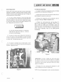
PREDELIVERY INSTRUCTIONS
The AMF Ski-Daddlers are shipped completely assembled
except for the windshield assembly and the ski assembly.
The series classification for each snowmobile is clearly
shown on the control panel. The Model Number and Serial
Number are permanently stamped on the nameplate
attached to the rear right-hand side of the main frame
assembly. When ordering accessories or replacement parts,
always indicate the correct Model Number and Serial
Number as shown on the nameplate.
These assemblies, plus the attach ing hardware will be found
in the shipping container. Carefully open the carton and
immediately inspect the equipment for any damage or
missing items.
IMPORTANT: The owner must retain the Skj-Daddler
Inspection Record, Form No . 4477QA. This form must be
shown to the dealer should any claim arise under the AMF
Warranty.
The following list identifies the Ski-Daddler series
classification, corresponding model numbers and engine
designation covered in this manual.
c
Series
Classification
IVIodel Number
Engine
MARK IV-300
MARK IV-400-D
MARK IV-400
SD15P10C
SD15P51A
SD15P51 B
JLO 295
Hirth 399
Hirth 399
1IIT
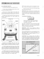
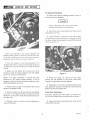
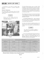
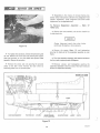
Install Ski Assembly
I
• Place the spindle pads (figure 1) in the spring
mounting bracket with the thicker section and the
directional arrow on the pad pointing forward. NOTE: The
spindle pads and attaching hardware, locknuts and 3-1/4-inch
length screws, will be found in the plastic bag shipped with
the sled.
SD15P10C
• Install the ski assembly by securing the spring
mounting bracket and spindle pad to lower end of spindle
tube assembly as shown in figure 1. Apply 30 foot-pounds
t orque to the locknut. Do not overtighten bolt as the ski
assembly should float freely on the spindle.
Monul",,",",', eng;ne code numbe,
Prepared for electric starter
Traction belt width in inches
Ski-Daddler
•
This manual is presented in two sections. The first section,
Maintenance, provides the instructions necessary for
maintenance and service while the second section, the
Illustrated Parts List is provided to facilitate the ordering
of spare and replacement parts.
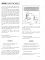
NOTE: Properly installed skis should toe out 0- to 1/2-inch
at the front end (see figure 2) and should be symmetrical
about the centerline of the sled. To align the skis, refer to
the Steering and Ski Alignment procedures.
The Parts List section also contains a numerical listing of all
items shown in the Illustrated Parts List. Thus, if the part
number is known but not its application, refer to the
numerical , ·st. If the part number is not known, locate the
item on the illustration to obtain the index number keyed
to the applicable parts list.
c
tliliJt)--- - -
IMPORTANT: To keep the AMF Warranty in force, be
certain to use only AMF-Approved replacement parts. The
AM F-Warranty does not apply to parts covered by the
original manufacturer's warranty such as engine or engine
parts, starters, belts, carburetor, battery or other
components or accessories not manufactured by AM F.
Should any claim arise concerning these items, follow the
manufacturer's instructions.
1003249
Repeat procedure for opposite ski.
Figure 1
3
SPINDLE PAD
(THICK SECTION
FORWARD)
/p'!S'3!PREDELIVERY INSTRUCTIONSI~
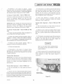
NOTE: Check mounting stri ps for sharp edges or corners.
Use a fine tooth file to smooth any sharp edges and corners.
Install Windshield Assembly
•
Disconnect hood harness at the quick disconnect.
• Attach the hood harness clip to the 7/8-inch length
screw and secure with locknut.
• Remove hood and headlight assembly. Refer to Hood
Removal and Installation procedure.
• Back off the locknut (figure 2) and remove the
7/8·inch length screw used to secure the hood harness clip
and the end of the right-hand mounting strip to the hood.
IMPORTANT: Before replacing the hood assembly, check
the steering column to insure that it is not too loose nor
too tight. Adjust the bolts securing the steering column and
U-strap at the roll bar as required to obtain good steering
response.
• Remove the remaining screws securing the right- and
left-hand mounting strips to the hood. Remove the
mounting strips.
Fuel Mixture Instructions
WARNING
WINDSHIELD TRIM
MOUNTING
STRIP, RH
,..----- -
!
~---~
,
I
/
Never fill the gasoline tank while the engine is
hot. Wipe off any spilled gasoline before
attempting to start engine.
MOUNTING
STRIP,LH
/
/X
I
The correct oil-to-gasoline ratio is 20: 1 (20 parts regular
gasoline to 1 part oil). Too much oil will cause carbon
deposits. Too little oil or a poor mix will cause insufficient
lubrication and possible engine damage.
SCREW
~==~ii==~-~..~
IMPORTANT: Gasoline and oil shou ld be mixed at
temperatures above zero. At temperatures below zero gas
and oil mix with difficulty.
Fuels containing additives are not recommended for use in
Ski-Daddler engines. For mixing with gasoline, use
AM F-nondetergent oil prepared exclusively for use in
air-cooled, 2-cycle engines.
IMPORTANT: Some outboard motor oils contain a
detergent that works well in outboard motors that operate
at much lower temperatures because they are water cooled.
However, the detergents may cause spark plug fouling in
the air-cooled engines used on Ski-Daddler snowmobiles.
MEASURING POINTS
TOE OUT O-TO 'h -INCH MAXIMUM
Figure 2
FUEL MIXTURE CHART
• Remove the protective plastic cover from the
windshield. Place the windshield in position on the hood
assembly. Replace the mounting strips as shown in figure 2.
OIL (Ounces)
4
• Using the original screws, loosely secure the mounting
strips and windshield to the hood assembly starting at the
center and working to the sides. Be certain to position the
7/8-inch length screw in the end position shown in figure 2.
8
12
16
20
24
28
32
36
40
GASOLINE
(Gallons)
• Engage the ends of the mounting strips to the trim
strip on the windshield and then tighten the screws , starting
at the ends and working to the center. Remove the
protective covering from the mounting strips.
2+--I---+-~r:;......-jIIE=--+--+-+--I--+'-'
GASOLINE/OIL RATIO - 20 to 1
4
1003249
)
[II
c
Use a mixture of gasoline and oil as shown in the Fuel
Mixture Chart. Never use gasoline left over from the
summer or previous winter.
SERVICE AND REPAIR
• Engage the left- and right-hand latch assembl ies to
secure the hood to the main frame.
•
IMPORTANT: The new no-lead antipollution gasolines may
contain additives that contribute to higher combustion
temperatures and varnish formation s that may cause engine
seizing. Use only normal leaded regular and premium
gasolines when mixing for use in the Ski-Daddler engines.
AMF Fiberglass Repair Kits are available through your
authorized AM F Distributor. For large repairs, order AM F
Fiberglass Repair Kit No. 1510693. Smaller repairs can be
made with Repair Kit No. 1510765. Paint all repaired areas
on the hood using AMF-Orange color paint available in
easy-to-use spray contai ner, AMF Part No. 1510828.
Follow the instructions in the kit when making repairs.
Replace Lamp Assemblies
Headlight. To replace the headlight bulb, raise the headlight
assembly; remove the screws securing the cover assembly
and remove the cover assembly. Remove the defective bulb
and replace with new bulb. See illustrated parts list for
correct replacement part numbers.
Lubrication
A low temperature grease must be applied to the zerk
fittings located on the steering spindle tubes; on each bogie
wheel after approximately each 20 hours of use; and the
chain case housing which must be checked after each 10
hours of use and No. 2 lithium bearing grease replaced as
required .
Taillight. Remove taillight lens to expose the taillight bulb.
Remove the defective bulb and replace with a new bulb.
See illustrated parts list for correct replacement part
numbers.
The bearing cup retainers that hold the seal beari ngs in the
traction belt take-up assembly used on Mark IV-300 and
-400 should be repacked with No.2 lithium bearing grease
whenever the bearings are removed during normal
maintenance. No . 2 lithium bearing grease may also be
applied to the inside of the drive sprocket bearing retainers
during normal maintenance .
Steering and Ski Assembly Alignment
Good steering ability requires that the skis be properly set
and aligned with the sled body when t he steering handle is
placed in the straight-ahead position. To determine that the
skis are properly aligned, measure the distance between the
inside edges of the skis at the front end and at the rear.
Properly aligned skis should toe out 0- to 1/2-inch
maximum at the front. If the skis or steering mechanism are
not properly set, adjust as follows.
No . 2 lithium bearing grease may also be applied as required
to the wearplates and U-strap securing the steering column
to the roll bar.
•
SERVICE AND REPAIR
• To remove the hood and headlight assembly,
disconnect the hood wiring harness at t he quick-disconnect.
Release the hood latch assembl ies and then remove the
hood and headlight assembly by lifting back end first.
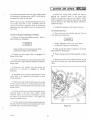
• Remove the bolt (1 , figure 3), two spacers (2),
bottom spacer and locknut secur ing the rod end bearing (3)
to the spindle arm (6).
• Loosen the jam nuts (4) securing rod end bearings (3)
at the spindle arm.
• To install the hood and headlight assembly, place the
hood in position on the sled so that the forward hood clip
and the bottom edge of the hood engages the clips along
the inside edge of the bumper.
1003249
Place steering handle in a straight-ahead position.
• Remove the hood and headlight assembly. Refer to
Hood Removal and Installation.
Hood Removal and Installation
c
Connect the hood wiring harness using the connector
plug.
Hood Assembly Repair
Mix the gasoline and oil thoroughly in a clean container
kept for this purpose only. The best way to ensure a good
mix is to pour the oil into a container with about one
gallon of gasoline and mix thoroughly. Then add additional
amounts of gasoline as shown on the Fuel Mixture Chart.
Fill Ski-Daddler gas tank from this separate container of
mixed fuel. Use a funnel with a fine-screen strainer when
filling the tank.
c
IM SI 3ij
NOTE: If both skis need adjustment, repeat procedure for
the opposite ski .
5
SERVICE AND REPAIR
)
To Remove Drive Chain
• Remove the hood and headlight assembly. Refe r to
Hood Removal and Installation.
Always disconnect spark plug wires before
working on the engine or drive elements.
• Remove the locknut securing the chain cover top and
remove chain cover top .
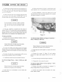
• Loosen the bolts (1, figure 4) on both cam up-rights
(2) and rotate the cam and shaft (3) as required to loosen
the chain tension . During reassembly, apply 30 foot-pounds
torque to the bolt (1).
Figure 3
• Move the affected ski into proper alignment and
recheck measuring points to insure that the skis toe out 0to 1/2-inch maximum at the front end and are in the same
or ientation with the sled body as shown in figure 2.
• With skis properly set and steering handle in the
straight-ahead positio n, rotate rod end bearing (3, figure 3)
as required to bring rod end bearing in line with the spindle
arm (6) .
• Secure rod end bearing (3) to spindle arm (6) as
illustrated . Check for proper alignment an d then tighten
jam nut (4) to secure rod end bearing.
Figure 4
NOTE: If a greater adjustment is required than that
permitted by the steering linkage assembly, it wi ll be
necessary to align the ski by making the adjustment at the
spindle tube assembly as follows:
• Remove the cotter pin, slotted nut and washer
securing the top sprocket to the driven clutch shaft.
Remove the top sprocket and chain together.
• Reassembly is the reverse of removal. Perform drive
chain adjustment procedures and add No. 2 lithium bearing
grease as required to the chain case.
• Remove screw (5, figure 4) and locknut (6) securing
spindle (7) to spindle arm (8).
• Remove spindle arm (8) and rotate ski and spind le
one notch in the required d irection; replace and secure
spindle arm to the spindle. Apply 20 foot-pounds torque to
the locknut (6).
Drive Chain Adjustment
A properly adjusted drive chain (figu re 4) should have a
1/8- to 1/4-inch slack. Check and ad just chain as follows :
• Remove the locknut securing the chain cover top and
remove chain cover top .
• Recheck the skis for proper toe out and alignment as
previously described.
6
1003249
~I SERVICE AND REPAIR Ita 2 'dij
c
Variable-Speed Drive Belt Adjustment
• Rotate the upper sprocket to tension one side of the
chain and then check the opposite side for proper slack. If
adjustment is required, loosen the screws (1) securing the
cam uprights (2) on each side.
Proper drive belt tension is obtained when opposite sides of
the belt can be squeezed, between the drive clutches, to the
following dimensions as measured between the top and
bottom outside su rface of the belt.
• Rotate the cam (3) counterclockwise to tighten or
until the chain is properly tensioned. Hold the cam in this
position while tightening the cam upright bolts (1) on each
side. Be certain the lateral alignment between the drive
clutch and the driven clutch (4) is maintained while the
cam upright bolts are tightened. Apply 30 foot-pounds
torque to the screw (1).
SD15PlOC
SD15P51A
SD15P51B
2-3/4- to 3-1/4 inches
4-1/4- to 4-3/4 inches
4-1/4- to 4-3/4 inches
Measurement must be taken as close to the drive clutch
flanges as possible. Be certain the driven clutch does not
open when belt is squeezed.
• Recheck chain tension before replacing the chain case
cover.
IMPORTANT: Do not use antislip belt dressing. Belt
slippage is a safety feature which prevents overstressing
drive-system components.
To Remove Variable-Speed Drive Belt
• To adjust drive belt tension, loosen the locknut (9,
figure 4) securing the clutch rod tensioner to the main
frame assembly .
• Remove the drive chain. Refer to paragraph To
Remove Drive Chain.
•
c
NOTE: If the drive belt is wearing unevenly. check
a Ii gn me nt as described in Drive Clutch Alignment
procedures.
Remove the clutch guard assembly.
• Loosen the locknut (9, figure 4) and serrated washer
(10) . During reassembly, apply 10 foot-pounds torque to
the locknut (9).
• Move the driven clutch (4) in the direction required
to obtain proper belt tension. Hold this position while
tightening the locknut (9) to secure the clutch rod
tensioner. Be certain the washer (10) and bar serrations are
properly engaged. Apply 10 foot-pounds torque to the
locknut (9) .
• Push the driven clutch (4) toward the drive clutch
sufficiently to allow removal of the variable-speed drive belt
from the drive clutch.
• Remove the locknuts (7, figure 6) securing the
bearing clamps (8) and remove the bearing clamps. During
reassembly, apply 5 foot-pounds torque to the locknuts (7).
To Remove Drive Clutch
• Remove the hood and headlight assembly. Refer to
Hood Removal and Installation.
• Lift the driven clutch and drive belt clear of the brake
assembly and remove the variable-speed drive belt.
• Install replacement drive belt. See illustrated parts list
for correct replacement part numbers.
Always disconnect spark plug wires before
working on the engine or drive elements.
NOTE: Variable-speed drive belt installation procedures are
the reverse of removal except that the belt must first be
placed around the driven clutch and then around the drive
clutch. After installation, perform the drive chain
adjustment, variable-speed belt adjustment and the drive
clutch alignment procedures.
•
• Loosen the locknut (9, figure 4) and serrated washer
(10) securing the clutch rod tensioner (11) to the main
frame. During reassembly, apply 10 foot-pounds torque to
the locknut (9).
c
1003249
Remove the clutch guard assembly.
7
SERVICE AND REPAIR
• Push the driven clutch toward the drive clutch
sufficiently to allow removal of the variable-speed drive belt
from the drive clutch .
A
• To remove the drive clutch from Models SD15P10C,
remove the clutch adapter bolt and washer. If necessary,
use a clutch puller and remove the drive clutch. During
reassembly, apply 4\5 foot-pounds torque to the clutch
adapter bolt. NOTE: If the clutch nut is removed from the
drive clutch used on Model SD15P10C, reinstall the nut,
apply 125 foot-pounds torque and be certain to engage the
lockplate tangs.
8
(TORQUE)
FT-LB
MODEL NO.
.240
45
SD15Pl0C
JLO 295
780
300
70
SD1SP5 1A
Hirth 399
911l
300
70
SD15P518
Hirth 3qg
910
ENGINE
CLUTCH
DRIVEN CLUTCH
• To remove the drive clutch from Models SD15P51A
and SD15P51 B, remove the clutch adapter bolt and washer,
flatten the lock plate tangs and remove the clutch nut and
lock plate. If necessary, use a clutch puller to remove the
drive clutch. During reassembly, apply 150 foot-pounds
torque to the clutch nut and then apply 70 foot-pounds
torque to the clutch bolt. Be certain to engage the lock plate
tangs.
HOLD DOWN NUTS
DRIVE CLUTCH
~VIEWO~
VIEW
0
Figure 5
NOTE: Drive clutch engagement speeds for the Mark
IV-400 and -400D may be increased to 2600 to 2800
engine RPM's by repositioning the clutch ramp plate from
level No.1 to position level No. 2.
• Tighten engin e holddown nuts and recheck
alignment. Apply 25 foot-pounds torque when tightening
the engine holddown nuts.
To Remove Driven Clutch
• Reassembly is the reverse of removal. Perform
variable-speed drive belt adjustment and drive clutch
alignment procedures.
NOTE: The procedures req uired to remove the driven
clutch are the same as those described in paragraph To
Remove Variable-Speed Drive Belt.
Drive Clutch Alignment
To Remove Brake Assembly
• Remove the hood and headlight assembly. Refer to
Hood Removal and Installation.
• Remove hood and headlight assembly. Refer to Hood
Removal and Installation.
Always disconnect spark plug wires before
working on the engine or drive elements.
•
Always disconnect the spark plug wires before
working on the engi ne or drive elements.
• Disconnect brake cable (3, figure 6) and housing at
brake mounting bracket and at brake actuating lever.
Remove the clutch guard.
• Loosen the engine holddown nuts (figure 5) securing
the engine supports to engine mount straps.
• Remove the two bolts and lockwashers securing the
mounting bracket to the driven clutch mounting.
• Place a straightedge on the fixed face of the drive
clutch and move the engine until the offset between the
straightedge and the front and rear edges of the driven
clutch is set to the A dimension as shown in figure 5.
Rotate driven clutch 90-degrees and repeat procedure.
•
Remove the brake assembly.
• Installation procedures are the reverse of removal.
Refer to Brake Adjustment procedures.
1003249
8
)
ERVICE AND REPAIR
c
To Remove Carburetor
Brake Adjustment
• Loosen the throttle wire adjustment screw and release
throttle wire at the carburetor (see figure 7) .
Check brake action before each start to insure proper brake
operation . If necessary, adjust the brake and apply Loctite
antiseize lubricant to the actuating cam lever (9, figure 6)
and the actual pins (10) as foll ows.
• Back off the screws and remove the air intake filter or
baffle (figure 8) mounted on carburetor.
• To apply antiseize lubricant, remove the cotter pins
(2) and the castle nut (4) . Remove the actuating cam lever
and apply lubricant to the cam lever surface that contacts
t he pins (10) . Remove the pins and apply lubricant to the
pins. Reassemble the cam lever and pins.
WARNING
• Remove the impulse line at the carburetor used on
the Mark IV-400 and -4000 Ski· Daddlers only.
• Release the tank-to-carburetor gas line (figure 7).
Wipe up any spilled gasoline immed iately. NOTE: On all
Mark IV·400 and -4000 series Ski·Daddlers, release the
carburetor-to-tank recirculating gas I'ine at the recirculation
elbow. Be certain to note the position of the gas lines to
insure proper reassembly. Wipe up any spi lled gasoline
immed iately.
I
Do not allow antiseize lubricant to contact the
brake pads (5, figure 6) or disk (1). To do so
will result in brake slippage.
• To adjust the brake pads (5, figure 6) to the disk (1),
remove the cotter pin (2) and tighten or loosen the castle
nut (4) as required to permit the brake pads (5) to just clear
the brake disk. Reinstall the cotter pin.
c
• To adjust for excessive play in brake cable or lever
position, loosen jam nuts (6) and move brake housing (3) as
required . Tighten jam nuts.
Figure 7
IMPORTANT: The Mark IV·300 uses a fuel pump (figurf
8) attached to the tank·to·carburetor gas line. If necessary
to replace the fuel pump, be certain to note the position 01
the pump to insure proper reassembly . Wipe up any spillec
gasoline immediately .
• Remove the nuts securin.9 the carburetor to the
intake manifold and remove the carburetor.
Figure 6
NOTE: Do not damage gaskets when removing carburetor.
c
1003249
9
SERVICE AND REPAIR
• Installation is the reverse of removal. Adjust
carburetor as described in Carburetor Adjustment
procedures.
The Bendix Model carburetor used on the Mark IV-300
Ski -Daddler is a float type carburetor and does not require
a recirculation system. The fuel is pumped to the carburetor through an external fuel pump mounted on the tank to-carburetor gas line. The carburetion system maintains a
fuel reservoir in the float chamber to insure smooth starting
and idling characteristics.
Carburetor Adjustments
The Tillotson Model HD carburetors used on the Mark
IV-400 and -4000 Ski-Daddlers are equipped with a recirculation system.
)
When adjusting the carburetor, best results will be obtained
if the adjustments are made on a warm engine. During
carburetor adjustments, DO NOT FORCE ADJUSTMENT
SCREWS INTO SEATS.
Never run the engine with the
carburetor-to-tank recirculating gas line
disconnected (see figure 7).
• TO ADJUST CARBURETOR - Close the high-speed
jet (DO NOT FORCE). Then open the high-speed jet (figure
7) to the settings shown on the carburetor settings chart for
your particular engine (see figure 9) .
The high- and low-speed jet adjustment screws for the
Bendix carburetor used on the Mark IV-300 Ski -Daddler are
located on top of the carburetor and are identified as HI
and LO.
The engine can be seriously damaged if
operated with a lean gas mixture (high-speed jet
turned in too far).
• Turn the low speed jet (idle-mixture screw) shown in
figure 7 all the way in (DO NOT FORCE), then open as
shown in figure 9 for the particular model sled. This
adjustment controls the mixture at idling speeds. A lean
idle mixture will result in poor acceleration.
Figure 8
CARBURETOR SETTINGS CHART
HIGH-SPEED JET
LOW-SPEED JET
MODEL NO.
ENGINE
SD15Pl0C
JLO 295
1-1/4 +1/8 Open
- 0
+ 1/8
1-1/2 _ 0 Open
SD15P51A
Hirth 399
1 + 1/8 0
_ 0
pen
+ 1/8
1 _ 0 Open
SD15P51B
Hirth 399
1 + 1/8
_ 0 0 pen
1 + 1/8 0
_ 0
pen
NOTE : The carburetor settings shown are for normal operation at sea level. For high altitude operation and for extreme
temperature variations, the settings may have to be adjusted accordingly .
Figure 9
10
1003249
J
SERVICE AND REPAIR
c
Keep t he idle speed slower than the clutch engaging speed
by adjusting the idle-speed screw. NOTE: Do not use the
low-speed jet to adjust for idle speed .
• Remove the carriage bolts, washers and locknuts
securing the mounting stra ps to the engine base.
Remo ve the mo unting straps and bar washers. NOTE:
During reassembly, the mounting straps and bar washer
must be secured to the engine base before installing the
replacement engine.
NOTE: Figure 7 shows a throttle·wire adj ustment screw. If
the throttl e plate fails to open completely when the
throttle control lever is depressed, loosen the throttle-wire
adjustment screw and readjust the wire as required to open
the th rottle.
•
Installation procedures are the reverse of removal.
To Remove Gas Tank
• Remove the hood and headlight assembly . Refer to
Hood Removal and Installation.
To Remove Engine and Support Assembly
• Remove the hood and headlight assembly. Refer to
Hood Removal and Installation.
Always disconnect spark plug wires before
working on the engine or drive elements.
• Check gas cap and indicator assembly to be certain
tank is empty, or nearly empty.
Always disconnect the spark plug wires before
working on the engine or drive elements.
c
•
Remove the gas cap and indicator assembly (1 , figure
• Remove the drive clutch. Refer to paragraph To
Remove Drive Clutch.
10).
• Loosen the flexible tube clamps securing the muffler
exhaust tube to the engine exhaust manifold and release the
exhaust tubes.
• Remove the bolts (3) and washers securing the gas
spill chute (2) to the main frame and remove the gas spill
chute.
• Disconne ct the throttle wire and remove the
carburetor as described in paragraph To Remove
Carburetor.
• Disconnect the wire leads and the ground wire at the
engine. Refer to the applicable wiring diagram to insure
proper reassembly .
• Remove the heat sh ield located between the engine
and the muffler. Remove the attaching hardware at the
muffler bracket, heat shield bracket and at the top near the
steering column .
• Remove the locknuts and washers securing the engine
mounting straps to the main frame. NOTE: During
reassembly, tighten the locknuts just sufficiently to permit
the washers to be turned by hand - then tighten the
locknuts one additional tum.
• Lift the engine until the engine mounting straps clear
t he studs. Rotate the engine counterclockwise and remove
the engine toward the rear and clear of the sled.
10032 49
Figure 10
11
AND REPAIR
• Remove the locknut (3, figure 11) securing the bogie
wheel assembly (2) to the axle shaft and remove the wheel.
• Disconnect the tank-to-carburetor gas line (6) and, on
the Mark IV-400 and -400 0 series the recirculating gas line
(7 ) at the gas tank outlet fitting (5). Wipe up any spilled
gasol ine immediately.
• During reassembly, torque the locknut (3) to 28
foot-pounds. Be certain the wheel assembly (2) is installed
with grease fittings on the outside.
• Remove the gas tank (4) by carefully sliding the tank
up and away from main frame. IMPORTAN T: Do not
damage the gas tank outlet (5) when removing the tank.
Do not attempt to make any repairs to the gas
tank. Use extreme care when removing the gas
tank. Do not remove tank near flame or open
fire.
• Gas tank installation procedures are the reverse of
removal. NOTE: If the original tank is not to be installed, it
will be necessary to remove the gas tank outlet (5) and the
attached gas line filter; also the pressure relief valve (8) .
These items are to be insta lled on the replacement tank.
Figure 11
To Remove Muffler
• Remove the hood and headlight assembly. Refer to
Hood Removal and Installation.
To Remove Bogie Wheel and Support Assembly Mark IV-300 and -400 only
Always disconnect the spark plug wires before
working on the engine or drive elements.
Always disconnect the spark plug wires before
working on the engine or drive elements.
• Loosen the flexible tube clamp securing the flexible
exhaust tube to the muffler and release the tube. NOTE:
All Mark IV -400 series Ski-Daddlers have dual exhaust tubes
and muffler.
• Raise back end of Ski-Daddler so traction belt clears
the ground .
• Remove the screws (1, figure 11) and washers
securing the bogie wheel support shaft (4) to the main
frame.
• Loosen the bolt and nut securing the muffler to the
mounting band assembly . Remove the muffler.
•
Installation procedures are the reverse of removal.
To Remove Bogie Wheel - Mark IV-300 and -400
only
•
Remove the bogie wheel and support assembly.
•
Reassembly is the reverse of removal.
To Remove Bogie Wheel Torsion Springs - Mark
IV-300 and -400 only
Always disconnect the spark plug wires before
working on the engine or drive elements.
• Remove the bogies as described in paragraph To
Remove Bogie Wheel and Support Assembly .
• Raise back end of Sk i-Daddler so that traction belt
clears the ground .
• Remove the support shaft and separate the bogie
wheel support halves.
12
1003 249
)
SERVICE AND REPAIR
To Remove Sprocket Seals and Bearings - Mark
IV-300 and -400 only
• Pry the tabs up sufficiently to remove the to rsion
springs. NOTE: The torsion springs are identified as right·
and left·hand springs. Note the direction of the coi ls and
the position of the springs to facilitate reassembly.
•
taSld
• Sprocket seals and bearings are located on each end
of the traction belt take-up assembly and the drive sprocket
assembly drive shafts. To replace the seals or bearings it will
be necessary to remove the traction belt take-up assembly
or the drive sprocket assembly as described in the
applicable paragraph .
Reassembly is the reverse of removal.
To Remove Traction Belt Take-Up Assembly Mark IV-300 and -400 only
• Remove the rear bogies. Refer to paragraph To
Remove Bogie Wheel and Support Assembly.
To Remove Drive Sprocket Assembly
• Remove the hood and headlight assembly and set the
machine on its right-hand side.
• Release track tensi on by loosening adjusting bolts (5,
figure 11).
• Release the support arm torsion springs connected to
the main frame .
Always disconnect spark plug wires before
working on the engine or drive elements.
• Remove the right- and left-hand adjusting angle
locknuts (6), washers and carriage bolts securing the
traction belt take-up assembly to the main frame .
•
c
• Remove the locknut securing the chain cover and
remove the chain cover top.
• Remove the lower sprocket from the drive sprocket
shaft and remove the sprocket and chain as descri bed in
paragraph To Remove Drive Chain.
Remove the traction belt take-up assembly as a unit.
NOTE: The traction belt take-up assembly consists of the
rear sprocket assembly, spacer and associated hardware held
together by the rear support arm assemblies. If necessary to
remove seals, sprockets or idler wheel, proceed as follows.
• On Mark IV-400D only, remove the suspension
assembly. Refer to paragraph To Remove Suspension
Assembly.
• Carefully pry the oil sea l away from the rear support
arm assembly (8, figure 11) and remove the support arm
and adjusting angle (9) clear of the sprocket shaft and
bearing.
• On Mark IV-300 and -400 only, remove the bogie
wheel and support assemblies. Refer to paragraph To
Remove Bogie Wheel and Support Assembly.
• Remove the press-on bearings and oil seals. During
reassembly repack bearings with No. 2 lithium bearing
grease .
• On Mark IV-300 and -400 only, remove the traction
belt take-up assembly. Refer to paragraph To Remove
Traction Belt Take-Up Assembly.
• Remove the screws (10) and nuts secu ring the
sprocket plate and the sprocket to the drive shaft. Remove
the plate and sprocket.
• Using a screw driver, carefully pry the oil seals (figure
12) away from the bearings at each end of the drive shaft.
• To remove the idler wheel , remove the screws (10)
and nuts securing the sprocket plates and remove the idler
wheel by stretching the wheel over the sprocket plates.
• Remove the carriage bolts and nuts secu ring the
bearing retainer to the chain case side of the main frame .
Remove the retainer. During reassembly apply No. 2
lithium bearing grease to the bearing retainers.
• Reassembly is the reverse of removal. During
reassembly follow instructions outli ned in paragraphs Track
Alignment and Track Tension Adjustment.
• Move the drive shaft and sprocket assembly toward
the chain side until the opposite end of the shaft clears the
bearing retainer. Remove the drive sprocket assembly.
1003249
13
~e2i31 SERVICE AND REPAIR I~
• Reassembly is the reverse of removal. During reassembly follow instructions outlined in the paragraphs Track
Tension Adjustment. Track Alignment and Drive Chain
Adjustment for the applicable sled_
To Remove Suspension Assembly -4000 only
)
Mark IV
• Remove the hood assembly and set the machine on
its right-hand side_
Always disconnect spark plug wires before
working on the engine or drive elements.
Figure 12
• Remove the screws (figure 13) and lockwashers
securing the back end of the suspension assembly to main
frame .
• To replace the sprockets. remove the ball bearing and
oil seal. Remove the screws and nuts securing the support
plate and sprocket to the drive shaft and sprocket plate
assembly. Remove the sprocket.
• Pivot the suspension assembly and traction belt about
the front axle to approximately gO-degrees.
• Remove the screws and nuts securing the sprocket
plates to the idler wheel. Remove the idler wheel by
stretching wheel over the sprocket plate.
• Remove screws and lockwashers securing the
suspension assembly to the front end of the main frame and
remove the suspension assembly.
MARK IV-400D
SKID FRAME ASSEMBLY
TRACTION BELT
EYE
PROPER TENSION
1- TO 1 'h -INCH PULL
ADJUSTING SCREW
JAM NUT
CLEATS
Figure 13
14
1003249
)
~I SERVICE AND REPAIR le2la~
c
o Installation is the reverse of removal.
During
reassembly, follow the instructions outlined in paragraphs
Traction Belt Tension Adjustment, Traction Belt Alignment
and Suspension System Adjustment for Mark IV-400D .
To Remove Traction Belt - Mark IV-400D only
• If the track is not centered, stop the engine and on
that side where the edge of the track is closest to the slide
rai l, rotate the adjusting screw (figure 13) until track is
centered. Pull the t rack for a few revolutions and then
start the engine and recheck alignment. Stop the engine and
lock the adjustment screw in this position.
To remove or replace the traction belt it is necessary to first
remove the suspension assembly and then the drive
sprocket assembly. Refer to the applicable paragraphs for
removal procedures.
• After t rack alignment is complete, check track
tension as described in paragraph Traction Belt Tension
Adjustment - Mark IV-400D only.
IMPORTANT: When installing the traction belt, follow the
Traction Belt Alignment - Mark IV-300 and -400
only
instructions outlined in paragraphs Traction Belt Tension
Adjustment, Traction Belt Aligjment and also recheck
Suspension System Adjustment for the Mark IV-400D .
• Set the snowmobile on a level surface and raise the
back end so the traction belt clears the ground.
To Remove Traction Belt - Mark IV-300 and -400
only
c
• Remove the bogie assemblies. Refer to paragraph To
Remove Bogie Wheel and Support Assembly .
• Stand to rear of sled and visually check the space
between the frame tunnel and the edges of the traction
belt. On a properly aligned track this space should be the
same.
• Remove the traction belt take-up assembly. Refer to
paragraph To Remove Traction Belt Take-Up Assembly.
NOTE: It is not necessary to disassemble the traction belt
take-up assembly when removing the traction belt.
• If the track is not centered, loosen the two locknuts
(1, figure 14) on that side where the edge of the track is
closest to the inside edge of the tunnel. Tighten the
adjusting screw (3) until track is centered.
• Remove the drive sprocket assembly. Refer to
paragraph To Remove Drive Sprocket Assembly.
•
Never run the engine inside a building without
first opening all doors and windows to insure
proper ventilation_
Remove the traction belt.
• Reassembly is the reverse of removal. During
reassembly follow instructions given in paragraphs Traction
Belt Alignment, and Drive Chain Adjustment for the Mark
IV-300 and -400 only.
• With the back end of the snowmobile raised, start the
engine. Allow track to rotate several turns and then recheck
track alignment to ensure that proper alignment is
maintained.
Traction Belt Adjustment
IMPORTANT: The traction belt must be checked regularly
for proper alignment and tension. When necessary to ·adjust
the belt, first perform the traction belt alignment and then
complete the traction belt tension adjustment for the
applicable sled.
MARK IV-300 and -400
Traction Belt Alignment - Mark IV-400D only
• Set the snowmobile on a level surface and raise the
back end.
• Stand to the rear of sled and visually check the space
between the slide rail and the edges of the track. NOTE: On
a properly aligned track this space should be the same. Start
the engine and agaio visually check to be certain the track
remains centered while the track is running.
1003249
Figure 14
15
SERVICE AND REPAIR::J
NOTE: A properly tensioned track should have a 1/2- to
1-inch sag at the app roximate top center of the track. This
can be determined as follows:
• After track alignment is complete, tighten all locknuts
(1) and then check traction belt tension as described in the
paragraph Traction Belt Tension Adjustment - Mark IV-300
and -400 only.
)
• Rest a straight bar (figure 15) of sufficient length
along the top surface and near the edge of the track. Insert
the straight ba r through the back end of the snowmobile
and check for proper sag. Repeat procedure on opposite
side and note the difference, if any, in the track tension.
Traction Belt Tension Adjustment - Mark IV-400D
only
• Set the snowmobile on a clean, flat surface and raise
the back end of the sled .
• Check traction belt tension by firmly pulling the
track downward at the center of the track . A properly
tensioned track should have a 1- to 2-inch clearance
between the Hi -Fax runner and the t rack cleats at the
approximate bottom center of the track. NOTE: Do not
attempt this with the engine running . Traction belt cleats
are sharp and must be handled carefully.
MARK IV -300 ANO - 400 ONLY
STRAIGHT BAR
TRACTION BELT
• If adjustment is necessary, loosen the locknuts (figure
13) on each side of the sled and rotate the adjusti ng screws
as required to obtain proper track tension. IMPOR TA NT:
Adjust both screws equally so as not to disturb the track
alignment. Retighten the locknuts on both sides of the
snowmobile.
Figure 15
• If adjustment is necessary, loosen the two locknuts
(1, figure 14) on each side of the sled just sufficiently to
allow movement of the belt-adjusting angle (2).
Never run the engine inside a building withqut
first opening all doors and windows to insure
proper ventilation .
• Turn the adjusting screws (3) clockwise to tighten
and counterclockwise to loosen until proper track tension is
achieved. IMPORTANT: Adjust both screws (3) equally so
as not to disturb the track alignment.
• Raise the back end of the snowmobile until the track
clears the ground. Start the engine and allow the track to
rotate several turns . Then, stop the engine and repeat the
track tension adjustment procedure to ensure that proper
tension is maintained .
Suspension System Adjustment - Mark IV-400D
only
Never run the engine inside a building without
first opening all doors and windows to insure
proper ventilation.
The suspension system may be adjusted for a soft or firm
ride, or for varying snow conditions. If a firmer ride is
desired, adjust the locknuts (figure 13) to tighten the
eyebolts located on each side of the track . Loosen the
eyebolts if a softer ride is desired. Adjust front or rear sets
of eyebolts equally.
• Raise the back end of the snowmobile until t he track
clears the ground. Start the engine and allow track to rotate
several turns. Then repeat the track tension adjustment
procedure to ensure that proper tension is maintained.
• Retighten the locknuts (1, figure 14) on both sides of
the snowmobile.
Traction Belt Tension Adjustment - Mark IV-300
and -400 only
Spark Plug Replacement
IMPORT ANT: Always check the traction belt for proper
alignment before performing the traction belt tension
adjust ment procedures.
•
To maintain good engine performance the conditi on of the
spark plugs should be checked periodically and the gap
reset to 0.020-inch using wire gauge. During reassembly,
apply 18 to 20 foot-pounds torque.
Set the snowmobile on a clean, flat surface.
16
1003249
J
SERVICE AND REPAIR
Spark plug condition may be determined by the color. A
carbonized pl ug is black; a burnt plug is pale grey, whereas
a normal functioning spark plug is brown .
ENG INE BACKFIRES THROUGH CARBURETORS.
Carburetor fuel-supply channel clogged. Carburetor set too
lean.
When replacing spark plugs, use a K-8 plug for ligh t service
and a K-7 plug for severe service to insure proper spark plug
heat ran ges for your particular engine. NOTE: Replacement
plugs should be U .S. Champion, AC spark plugs or
equivalent availab le at your authorized Ski-Daddler Dealer.
ENGINE BACKFIRES THROUGH EXHAUST. Incorrect
or faulty spark plug(s); faulty ignition coil or condenser;
loose ignition wiring.
ENGINE OVERHEATS. Insufficient or incorrect grade oil
in fuel mixture; carburetor or fuel line partly clogged;
carbu retor setting too lean; ignition timing too slow.
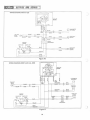
Wiring Diagrams
Electrical wiri ng diagrams are provided for the trained
technicians using this manual. Each diagram is identified
with the model number of t he snowmobile to which it
applies (see figures 16 and 17).
EX CESSIVE FUEL CONSUMPTION. Carburetor fuel line
or gas t ank leaking; choke closed; incorrect carburetor
setting.
TH ROTTlE CONTROL. Excessive play in throttle control
lever cau sed by loose throttle control cable.
Troubleshooting
ENGINE HARD TO START. Fuel line blocked or leaking;
ruptured fuel -pump diagram; water in fuel, flooded, loose
impulse line; ignition or switch wiring loose or grounded;
spark plug(s) fouled or f aulty; contact breaker points pitted
or burned.
c
eSIR
STEERING. Poor steering ability caused by improperly
adjusted skis ; steering linkage loose or out of adjustment.
U-bracket bolts on roll bar too tight or too loose. Spring,
U-bracket loose.
ENGINE STOPS. Fuel tank empty; fuel flow obstructed;
ignition system faulty. 'Spark plug(s) fouled or d irty. Engine
too hot and pistons seizing; carburetor setting too lean or
incorrect grade of oil being used, impulse line loose.
BRAKES. Excessive play in hand brake due to loose brake
cable or worn pads.
TRACTION BELT. Poor traction; check traction belt for
alignment and tension; worn sprockets or flipped bogies on
Mark IV-300 and -400 o nly.
ENGINE STOPS, FU EL TANK HALF EMPTY. Be certai n
the gas tank-to -carburetor line used on all the Mark IV-400
and -400D series Ski-Daddlers is connected to the OUT
fitting on the gas tank outlet and to the in let fitting on the
carburetor. The recircu lati ng, ca rburetor-to-tank line must
be connected to the I N fitting on the gas tank outlet (figure
10) and to the recirculating elbow (figure (7).
CLUTCH . Automatic cl utch fails to engage at proper RPM's
as shown in the foll owing chart. Check variable-speed dr ive
belt for proper tension alignment.
NOTE: Drive clutch engagement speeds for the Mark
IV-400 and -400D may be increased to 2600 to 2800
engine RPM's by repositioning t~e clutch ramp plate from
level No. 1 to position level No. 2.
ENGINE OPERATES I RRE GUlARlY . Spark plug loose,
fouled or faulty; ignition switch wiring grounded;
carburetor out of adj ustment or dirty . Engine holddown
bolts loose; ignition tim ing off.
ENG I NE WOR KI NG FOU R-STROKE. Choke shut;
carburetor settings incorrect; dirt preventing carburetor
inlet needless from seating properly.
CLUTCH ENGAGEMENT SPEEDS
ENGINE lOSES POWER . Poor compression due to loose
head and crankcase bolts. Faulty ignition; timing; piston
rings stick ing due to the use of improper oil. Carbon
deposits in cylinder.
1003249
17
CLASS
ENGINE
ENGINE RPM
MARK IV-300
MARK IV-400D
MARK IV-400
JlO 295
Hirth 399
Hirth 399
2300 to 2500
2400 to 2600
2400 to 2600
SERVICE AND REPAIR
WIRING DIAGRAM, MARK IV-300
--I
~-
: ~~
~-f~ , ~
:lm~
:M'-~'
t'W
~
~":.
TAILLIGHT
BLACK
7
YELLOW
BLUE
BLUE
3:
>
'"
i'
BLACK
r --.::L..' QUICK-KILL
WHITE
~+--===--<.~----'=='-----t~!i·~lJ SWITCH
3:
31br~
\
~~
:
LI GHTS OFF
START
',4
!/
'
BLUE
53C
BLUE
.---.. HEADLIGHT
~ GE 4461
~---------B-LA-C
-K--~~
6eWATT
50
~53a
.~
31J
BLACK
BLACK
QUICK
DISCONNECT
I
\
)~
~
IGNITION
SWITCH
OFF
0
BLACK
0
-'
-'
w
LIGHTS ON
ENGINE
~-~
~)~______~~~>-____--,
GE67
6 WATT
)
YELL OW
53
WHITE
BLACK
Figure 16
WIRING DIAGRAM, MARK IV-400 and -4000
rr==-HIRTH-399
ENGINE
3:
o
><
~
j
~
ww~
6~:ir
~
NOT
USED
TACHOMETER
(OPTIONAL)
a:
,..-
____-=-W:..;.H.:..:IT.:..;E=--.:..;R.::E=-D+-_~~
r;::+J"o-_ ___ __-"-B"'LA"'C""K"-_-:~~>---'B"'L"'A"'C"'K'-----+--+--+---.---=B:=L:.:A.::C:.:K_-4_ _7>~
.....
,>--;:;;-;=---7'>-~;;;-;~---,
//
BLUE
7
BLUE
YELLOW
QUICK-KILL
SWITCH
WHITE-RED
~
WHITE
IGNITION
SWITCH
LIGHTS ON
OFF
19 9'
BLUE
~y
- - - - - - - -' I
_!":_A!:K___ __ -.J
\
LIGHTS OFF
/
BLACK
START
53C
BLUE
BLUE
BLUE
:l~!
Ll:J
50
QUICK
DISCONNECT
.-..-,f--~ 53a
53
rT'
YELLOW
WHITE
WHITE-RED
Figure 17
18
BLACK
BLACK
BLACK
BLUE
BLUE
!1
HEADLIGHT
GE 4461
60 WATT
~
~I
IL LUSTRATED PARTS LI ST
Where no code letter appears in the code co lumn, the part
is used on all models to which the particu lar figure applies .
This section of the dealer's manual consists of an illustrated
parts list and a nume ri cal index.
All model codes will be li sted at t he bottom of each parts
list page to provide a ready reference.
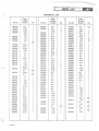
PARTS LIST
Th e pa rts-I i st consists essentially of exploded -view
illustrations keyed to the figure-reference column by index
num bers. The Parts List is arranged in the following
columns:
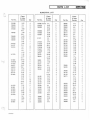
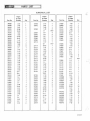
NUMERICAL INDEX
The numerical index is provided to afford dealers and
d istributors with a means of determining to which models
their stock applies. The index consists of the following
t hree co lumns:
Figure-and-Index Number. The number preceding the dash
refers to the figure number on which the item is shown .
The number following the dash is the index number keyed
to the item shown on the exploded view .
Part-Number Column. The part-number co lumn tabulates
all parts called out in the parts list. The part numbers are
listed in numerical order starting with the first digit in the
number.
Part Number. The part number column identifies the item
by its assigned part number.
.Description.
Index-Number Column . The index-number column reflects
the figure-and -index number of the part within the Parts
List. The number preceding the dash refers to the figure
number on which the item is shown. The number following
the dash locates the item within the given figure.
The description column identifies the part
with descriptive nomenclature .
Quantity. This column provides the total number of items
required per assembly.
c
Quantity Column. The quantity column reflects the total
n u m be r of parts required for the particular
figure -and-index-number applicati on. In certain cases,
quantities differ between sled models. This circumstance is
covered by providing the larger quantity for the particular
figure-and -index number. In refe rring to the given
figure-and-index number in the parts-list section, the proper
quantity per sled may be determined .
Model Code. This column identifies, by code letter, the
Ski-Daddler models for which the part applies . The
following lists the code-to-model relationship:
Model
SD15P10C
SD15P51A
SD15P51B
10032 49
Code
A
B
C
PARTS LIST
Series
MKIV-300
MKIV-400D
MKIV-400
19
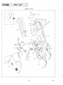
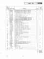
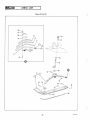
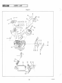
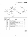
PARTS LIST
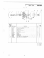
Figure 1 (1 of 2)
)
)
20
1003 249
~I
c
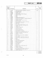
Figure
& Index
Number
1-
-1
-2
-3
-4
-5
-6
-7
-8
-9
-10
-11
c
-12
-13
-14
-115
-16
-17
-18
-19
-20
-21
-22
-23
-24
-25
-26
-27
-28
-29
Part Number
10031 00
1003101
1003105
1003197
1003238
1003525
1003461
1003462
1003189
1003356
1003190
9415426
33808
9000123
181648
120394
90001 25
1003163
1003389
1003219
1003340
1003304
9413314
9000123
450590
446188
9000124
274865
37351
181581
120392
9000123
37122
1003350
9000821
1003180
1003181
9000324
32532
32528
1003026
33769
37595
9000125
PARTS LIST
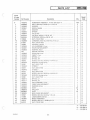
Description
SK I-DADDLER, MA RK IV, MOD EL NO. SD15P10C . .. . .. .. . .
SKI-DADDLER, MARK IV, MOD EL NO. SD15P51A . . .. . .... .
SK I-DADDLER, MARK IV, MODEL NO. SD 15P51 B .. . . . .. .. .
HOOD AND HEADLIGHT ASSE MBLY (See figu re 2) . . .. .. .. .
HOOD AND HEADLIGHT ASSEMBLY (See figure 2) ... . .... .
WINDSHIELD, 15 IN ... .... . . . ... .. ...... . .. . . . . . . . .
BUMP ER ASSEMBLY, RH (See figure 2) .. . . ...... . . .. . .. .
BUMPER ASSEMBLY, LH (See figure 2) . . . . . . .... . . . ... . .
ROLL BAR AND STEERING ASSEMBLY (See figure 3) .... . . .
CONSOLE AND STEERING ASSEMBLY (See figure 3) . ...... .
CONSOLE AND STEERING ASSEMBLY (See figure 3) . . . . ... .
SCREW, Truss HD, 1/4-28 THO by 1-1/2 IN . LG ....... . .. .. .
WASHER, Formed .... ........ ...... . . ... .. .. . .... .
LOCKNUT, 1/4-28 T HO . . . . . . . . . . . . . . . . . . . . ........ .
SCREW, HEX HD, 3/8 -24 THO by 2 IN. LG . ..... ...... .. . .
WASHER, Plain, 13/32 IN. ID
LOCKNUT, 3/8-24 THO . . . . . . . . . . . . . . . . . . . . . . . ... . . .
SKI AND SPRING ASSEMBLY (See figure 3) . . . . . . . . . . . . . . .
SKI AND SPRING ASSEMBLY (See figure 3) ..... . . ....... .
SKI AND SPRING ASSEMBLY (See figure 3) ....... .... ... .
SEAT AND TAIL LAMP ASSEMBLY (See figure 4) . ......... .
SEAT AND TOOL BOX ASSEMBLY (See figure 4) ...... . ... .
LOCKNUT, 1/4-20 THO . . . . . . . . . . . . . . . . . . . ....... .. .
LOCKNUT, 1/4-28 THO .. . . .... . ... . . ..... . . .. .... . .
WASHER, Plain, 9-32 IN. 10 by 5/8 IN. 00 ... .. .......... .
WASHER, Plain, 17/64 IN. ID by 5/8 IN. 00 . . . . . . . . . . . ... .
LOCKNUT, 5/16-24 THD . . . . . . . . . . . . . . . . . . . . . . . . . . . .
WASHER, Plain . .... . ...... . .. ........ . . . . . . . . . . . .
HINGE, Hitch ......... .. . . . . . . . . . . . . . .. .... .... . .
BOLT, HEX HD, 1/4-28 THO by 2-1/2 IN. LG .... . ..... . .. .
WASHER, Plain, 9/32 IN. ID by 5/8 IN. 00 ..... . ... . ..... .
LOCKNUT, 1/4-28 THD ... . ..... ......... .. ........ .
MODEL TAG, Sk i-Daddler .. .... .......... ... ........ .
MODEL TAG, Ski-Daddler . .. .. .... ... ...... . ... .. ... .
POP RIVET . . . . . . . . . . . . . .. ..... ........ .. . . .. ... .
ENGINE AND SUPPORT ASSEMBLY (See figure 5) ... .. ... . .
ENGINE AN D SUPPORT ASSEMBLY (See figure 6) . .. ..... . .
BOLT, Carriage, 3/8-24 THD by 2-1/4 IN. LG . ... .......... .
NUT . .. . . .. . ...... ..... .. . .......... . ... ... . . .
BUSHING . . . . . . . . . . . . . . . . . . ... .... . ...... . ..... .
SPACER , Rubber ... . .. ..... ... .......... . .. . .. . .. .
SPACER, Rubber . . . . . . . . . . . . . . . ..... .......... . .. .
WASHER, 13/32 IN. ID by 1-1/2 IN . 00 .. . ... . . . ... ..... .
LOCKNUT, 3/8-24 T HO ......... ... . .. . ... .... .. . . . .
leSl3~
Qty
1
A
B
C
A
BC
1
1
1
1
1
1
A
B
C
1
1
1
1
4
4
4
2
4
2
2
2
2
1
1003249
21
A
B
C
2
4
2
4
2
2
A
BC
A
BC
A
BC
BC
BC
1
1
1
1
1
1
AC
B
1
2
1
1
4
4
4
4
4
4
4
A B C -
c
Model
Code
A
BC
BC
A
BC
SD 15P1 0C
SD 15P51A
SD15P51 B
PARTS LIST
I~
Figure 1 (2 of 2)
¥
/;
\.
.
/
1003249
22
~I
c
Figu re
& Index
Number
1-30
1003028
33768
-31
-32
-33
-34
-35
-36
-37
-38
-39
-40
1003324
9415426
33808
9000123
147579
1003365
1003366
436752
9000122
1002092
1003372
9000323
456145
9000124
37083
181595
138485
34960
1003371
1002803
9000828
1002808
9000827
1003434
1003433
1003173
1003174
181643
120382
37 113
100261 8
37683
1002642
9000823
446143
1003142
1003143
1003144
706
37389
100327 1
1003261
-41
-42
-43
-44
-45
-46
-47
c
Part Number
-48
-49
-50
-51
-52
-53
-54
-55
-56
-57
-58
-59
-60
-61
-62
-63
-64
-65
IM 21 d ij
PARTS LIST
Qty
Description
SHOCK MOUNT
SHOCK MOUNT
HEAT SHIELD _ .. _ .. _ . . . .. . . . . . _ .. _ _ .. . _ . __ ... - . .
SCREW, Truss HD, 1/4-28 THO by 1/2 IN. LG _ ...... _ . __ . . .
WASHER, Formed __ .. __ .... .. . ... _ .. .... _ ... .. . .. .
LOCKNUT, 1/4-28 THO _. _ .. . ...... . _____ ......... - .
WASHER, Plain . . _ .. _ . . _ . _ ... __ .. . .. __ ....... . . .. .
MUD F LAP, 15-1 N. _. _ .. _____ .. _ . _ .. _ .. _ .. _ . . .. ... _
STRAP .. .. _ ... __ .. ... .. _ . . ... .... _ . _ . . .... - . - ..
SCREW, PAN HD, 10-32 THO by 3/8 IN. LG _ ..... _ . _ . ___ ..
LOCKNUT, 10-32 THO. _ ........ _ .... ..... _ . .. _ . . .. .
TRACTION BELT TAKE-UP ASSEMBLY (See figure 7) .... _ __ .
SUSPENSION ASS EMBLY, 15-IN_ (See figure 9) _ .. _ .. ... . . _ .
BOLT, Carriage 5/16-24 THO by 3/4 IN. LG .... _ ..... . .. _ _ .
WASHER, Flat, 5/16 IN_ ID ... .. ..... _ . _ ..... ....... . .
LOCKNUT, 5/16-24 THO . .. .... _ . _ . . . . . __ ..... _ - . . . .
BOGIE ASSEMBLY (See figure 8) ...... _ ... . _ . _ . _ . .. . _ . .
SCREW, HEX HD, 5/16-24 THO by 3/4 IN_ LG . _ ..... _ . . . .. _
LOCKWASHER . .. _ . _ .. _ ... ... _ . _ . .... _ .. .. .. .. . .
BELT, Traction, 15-inch ........ .. . _ _ . ...... __ _ ... _ _ .
BE L T, Traction, 15-inch .. . .. . ... ... _ .... .. . . _ ...... .
GU IDE, Track ... .. _ .. _ _ ... _ . _ . ... . .. .. _ ..... _ . .. RiVET ... .. _ ..... _. _. _. . _ . . . .. ... _ _ ...... _ . . ... _
CLEAT, 10-hole .... _ ... _ . . . . ...... .. . . __ .. _ ...... _
RIVET .. . _. __ . __ ... . _. _. __ . _. _ . _ . _ __ ... _. _ _ .. _
BELT, Track, 3-in ch ... ___ .. _ . . _ ..... _ .. _ ... _ . _ _ ... .
BELT, Track, 6-inch .. . ...... _ .... _ .. . __ .. .. _ . _ .... .
DRIVEN CLUTCH AN D CASTING ASSEMBLY (See figure-l0) . _ .
DRIVEN CL UTCH AND CASTING ASSEMBLY (See figure 10) .. _
BOLT, HEX HD, 3/8-24 THO by 1-1/2 IN _LG .. . . _ . _ . .. _ .. .
LOCKWASHER, Spring, 3/8 IN . 00 . _ . _ ..... _ .. __ . _ . ... .
DRIVE SPROCKET ASSEMBLY (See figure 10) _. _ . _ . .. . ... .
DRIVE SPROCKET ASSEMB LY (See figure 10) _ .... .. _ .... .
GAS CAP ASSEMBLY, Tank (See figure 11) . _ . .. __ . __ ... _ ..
BODY STR IP, Wear _. _ __ . __ . _ . _ .... __ ... . ___ . _ . ... .
POP RIVET, 5/32 DIA . _ . _ .. __ . .... . _ .... _ . _ . _ . ....
WASHER, 3/16 IN_ ID . _ . _ . _ .. _ ... _ ...... . __ . _ .... .
MA IN FRAME ASSEMBLY, Weldment .. .. _ .... _ ... .....
MAIN FRAME ASSEMBLY, Weldment .. __ ..... __ . _ . __ ..
MAIN FRAME ASSEMBLY, Weldment ...... . . __ . _ .. _ . . .
GREASE FITTIN G ... _ . _ ......... _ ..... . _____ ....
CABLE TIE _. __ . ___ . . .. . ... . ...... _ .. _ . _ . .. _ . __
PASSENGER GRIP, Short ...... _ _ . .. ... ... _ ... ......
PASSENGER GRIP, Long . ..... _ ... _ _ .. _ .. _ . _ ..... ..
.
.
.
.
.
.
.
.
.
4
4
A
BC
1
1
1
1
1
1
BC
BC
BC
BC
BC
B
B
B
B
AC
B
AC
AC
AC
AC
AC
AC
AC
B
B
B
B
B
B
B
A
BC
2
4
4
1
1
2
2
2
3
6
6
1
1
21
42
41
368
2
1
1
1
2
2
1
1
1
AC
B
2
B
B
B
A
B
C
20
20
1
1
1
2
1
1
1
A B C -
c
100 3249
23
Model
Code
A
BC
SD15P l0C
SD 15P51A
SD 15P51 B
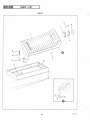
~eMlal
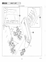
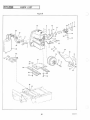
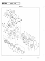
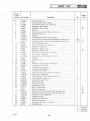
PARTS LIST
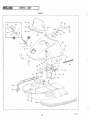
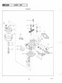
Figure 2
42
49
55
54
1003249
24
c
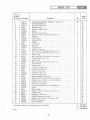
Figure
& Index
Number
Part Number
2-
1003 197
1003238
34984
3427 1
37045
1003354
37000
132908
90001 22
37006
9000 122
37005
1003312
34991
445170
37001
3705 1
*1 00330 1
*1003214
12481 8
1003253
34058
1003213
37055
437028
35027
35028
941 4492
35029
35023
35024
100321 5
100327 6
9000884
37009
9000461
35022
9000824
4461 52
37033
37034
900094 1
9000942
-1
-2
-3
-4
-5
-6
-7
-8
-9
-10
-11
-12
-13
c
-14
-1 5
-16
-1 7
-18
-19
-2 0
-21
-22
-23
-24
-25
-26
-27
-28
-29
-30
-3 1
-32
-33
-34
Description
HOOD A ND HEADLI GHT ASSY (See f igure 1) . . . ..... . .. . . .
HOOD AN D HEADLI GHT ASSY (See f igure 1) . . . .. . . . . . . . . .
CLIP, Hood ....... . .. . ..... . .. . .. . ...... . .. . . . . . .
RiVET ... . ... . ...... . . . .... . . ... . . . .. . . . . . . . . . .
PLATE, Hood . . ... .. . . . .. .. . . .. ... . .. . . . . . . .. . .. .
GAS LID AN D HING E ASSY . .. . ... .. . .. . . ... . ... . . . . .
GAS LID AN D HING E ASSY . . . . . . . .. . .. .. .... ... . . . . .
SCREW, RD HD, 10-32 THD by 1/2 IN. LG ........ . ... .. .
LOCK NUT, 10-32 THD . . . . . . . . . . ... . ..... . . . . . .. ... .
HINGE ASSEMBLY . .. . .......... . . . ... ... .. . . . . . . .
LOCKNU T, 10-32 THD . .. . ... . .... .. . .. .. . . .. .. .. .. .
SPRING, Fl at .. . .. . . . ..... . . . .. . . . . . .. . . . . . ... .. .
DECAL ... ...... . . . .. .. . ... . ... .. . . ..... . . .... .
ESCUTCHEON, Gas cover . ... ... . . .. . .. _ _ . . . . .... . .. .
NUT, Spring, 3/16 IN . .. ... . . . .. . . ... .. .. .. .. . . . . ... .
GAS LID ASSEM BLY . ....... . . . . .... . _ ... . . . . .. .. . .
RUBBER BUMPER, Gas lid ... .. . . . . . . . . . . . . . .. . . . ... .
HEADLIGHT ASSEMBLY ... .. .. ... . .. . . . ..... . . .. . . .
HEAD LIGHT ASSEMBLY . . .. .. . ... . . .... ... ... . . . . . .
JAM NUT, HEX HD, 1/4-20 TH D . . . . . .. .. ... . .. . . . . . . . .
PLATE, SWITCH .. . . . . . . . . . .. . . . . . . .. . . . . . . .. .. . . .
LOCKNUT, 1/4-20 T HD . . .. .. ... . . .. . . . . . . .. . . .. ... .
COV ER ASSEM BLY, Headlight . .. . .. . . . ... .. ... ... . .. .
COVER ASSEMBLY, Headl ight . .. . . . . . .. ... . . .. . .. . . . .
SCRE W, PAN HD, 8-32 TH D by 1-1 /4 IN. LG ... . . . . . . . . . . .
SHAFT, Pivot _. .. . . . . . . . .. . .. . ... . . . ... . ... .. ....
SHAFT, Spring ... ... ... . . .. . . . . .. .. .. . . . . . . . . ....
SCREW, Truss HD, 8-32 TH D by 3/ 8 IN. LG .. . ... . ... . . ...
SPR ING, Extension . . . . .. .. . .. . ... . . . . . .. . ... .. .. . .
BR AC KET, RH . . .. . . .. . . . . . . . . .. .. .. . . . . . . ... .. . .
BRACKET, LH . ... . . .. .. . ... ... . . . . . .. . .... . . .. .
HAR NESS, Hood . . . . ... .. . .. . . .. . . . . . .. .. . .. . .. . . .
HARN ESS, Hood .... .... ... . .. .. . .. ... . . . .. ... . . . .
HEADLIGHT . . . . . . . . ... . ... . .. . .... ... ... .. . . . . .
HOUSI NG ASSEMBLY (Consists of items 27 and 28) . . . . . . . . . .
RIVN UT,8-32 THD . . . . . . . . . . . . . . . . . . . . . . . . . . . . . . . .
HOUSING ..... . . . . . . . . . . . .. ... . . . .. . . ... . . .. .. .
POPRIVET . .... ..... .. . .... . ........ . . .... ... . . .
WASH ER . . .. . . . . . . . . ... . . .. .. .. .. . . . . . . . .. . .. . .
T RIM STRIP, RH . . ... .. . ... . . ..... . . . . . .. .. . . .... .
TRI M STRIP, LH . . ....... .. . ... . .. . .. .. . ... .. .. . . .
SCREW, Truss HD, 1/4-20 THD by 5/8 IN. LG
. . . . .. . . . . . . .
SC REW, Truss HD, 1/4-20 by 7/ 8 IN . LG . . . . ... . ..... . .. . .
RE F
REF
1
3
1
1
1
Model
Code
A
BC
A
BC
2
2
1
2
1
1
1
4
A
BC
BC
1
2
1
1
A
BC
4
1
4
A
1
1
2
1
1
4
2
1
1
1
1
A
BC
A
BC
1
1
2
1
4
4
1
1
6
1
A
A
A
A - SD1 5P10C
B - SD 15P51A
C - SD1 5P51 B
* Includes applicable items -1 7 through -28.
c
100 3 249
Oty
25
QMi3
Figure
& Index
Number
2-35
-36
-37
-38
-39
-40
-41
-42
-43
-44
-45
-46
-47
-48
-49
-50
-5 1
-52
-53
-54
-55
PARTS LIST
)
Part Number
9413314
1002166
9000555
34992
445170
35011
34271
1003252
35017
34989
34271
35005
9000123
34983
37591
1003461
1003462
37072
1003254
1003265
181566
1002589
Description
..
LOCKNUT, 1/4-20 THD · .
·.
· . · . · . · . ....
CABLE TIE . .
. .. . . . . . · . . ...... · . · . · . · .
·.·.
JACKNUT, Molly
·.
· . · . · . .......... . ............ . · . · .
ESCUTCHEON, Side
·.·.
· . . . . . . . . . . . ...... ...... · .
NUT, Spring
. . . . . · . · . · . · . · . · ..
· . . .. . . .. .. .. . .. . . ......
STRIKE
..·.
· . . . . .. · . . · . · . . . . . · . · . · .. · .
RIVET
. . · . . . · . . ...... · . · . · . · . ........ . . . . . · . · . · .
HOOD AND SWITCH PLATE ASSEMBLY · .
. ...... · . · .
·.
HOOD . .
· .. · . · .. · . · . · . . . . .
·.. . . . ·.·.
CATCH, Hood · .
· . · . · . · .. . . . . . . · .. · .. . ...... · .. · .
. . · . · . · . · . · . · . .. . . . · . · . · . · . · . · . · .
RIVET . .
GUlDq, Hood . . . . · . . . . . . . · . .............. · . . . . · ..
·.
LOCKNUT, 1/4-28 THO · . · . · . · . · . · . · . · . . · . · . · .
·.
SPACER, Bumper
· .. · . · . · . . . . . . ...... . .. .... . · . · . · . · .
COVER, Bumper .. · . · .. · .
· . · . · . · ..
BUMPER ASSEMBLY, RH (See figure 1) ...... . · . · . · . · . · . · . · .
BUMPER ASSEMBLY, LH (See figure 1) · . · . . .......... . ...... · . · .
SWITCH, Key (with keys) · .. · .
..
...
...
DECAL, Key switch · .. · . · .
·.
·.·.·.
·.·.
DECAL . .
. ...... · .
·... . . . . .
·.·. ·. ·. ·.·.·.
SCREW, HEX HD, 1/4-28 THO by 3/4 IN. LG ...... . .... . . . . . . · .
STOP, Hood
· . · . · . . . . . · . · .. · . . . . . . . . · .. · . · .. · .
Oty
1
1
7
2
6
2
4
1
1
2
4
6
6
6
1
REF
REF
1
1
1
2
1
A B C -
26
Model
Code
A
BC
A
A
A
)
SD15P10C
SD15P51A
SD15P51 B
100 3249
~I
c
Figure
& Index
Number
3-
-1
-2
-3
-4
-5
-6
-7
-8
-9
-10
-11
-12
-13
-14
-15
c
-16
-17
-18
-19
-20
-21
-22
-23
-24
-25
-26
-27
-28
-29
-30
-31
-32
-33
-34
-35
-36
-37
c
Description
Part Number
1003189
1003356
1003190
*37040
33320
181651
21777
30251
9000125
37041
181643
21777
9000125
30081
124925
37042
181578
147579
147579
34688
34694
34689
9000123
9000123
37231
32185
142443
9000122
32187
9417420
32188
32186
1002782
32286
32286
37159
37486
1003362
34946
**1003250
*1003343
*1003342
9415426
33808
ROLL BAR AND STEERING ASSEMBLY (See figure 1) ..... .
CONSOLE AND STEERING ASSEMBLY (See figure 1) .......
CONSOLE AND STEERING ASSEMBLY (See figure 1) .. .....
STEERING LINKAGE ASSEMBLY ...... .. .. . ... ......
ARM, Spindle .. ... ......... . . . . . . . . . . . . . . . . . ....
BOLT, HEX HD, 3/8-24 THO by 2-3/4 IN. LG . ... ...... ...
SPACER .... ... . .. .. . . .... .. ... . . .. . .. ... . . ....
SPACER . .. .. ..... ...... ... .. . .. .... ...... ... ..
NUT, 3/8-24 THO . . . . . . . . . . . . . . . . . . . . . . . . . . . . . . . .
TIE ROD ASSEMBLY ... .. . . . . . . . . . . . . ... .. . ......
BOLT, HEX HD, 3/8-24 THO by 1-1/2 IN. LG ..... ... .. ...
SPACER ..... .. . . . . . . . . . . . . . . . ...... . ........ . .
NUT, 3/8-24 THO ...... . . . . . . . . . . . . . . . . . . .. . . ....
ROD END . . . . . . . . . . . . . . . . .. . . . . . . . . . . . . . . . . . . .
JAM NUT, HEX, 3/8-24 THO . ... .. . . . . . . . . . . . . . . . , ...
TIE ROD . . . . . . . . . . . . . . . . . . . . . . . . . . . . . .. ...... .
BOLT, HEX HD, 1/4-28 THO by 1-7/8 IN . LG . . . . . . . . . ....
WASHER, Plain, 1/4 IN . ID . ........ . ..... . . .. .......
WASHER, Plain, 1/4 IN . ID ..... . ... . ...... . .. ... .. . .
U-STRAP ..... ... ........ .. .... . . . . . . . . . . . ... ..
WEARPLATE . . . . . . . . . . . . . . . . . . . . . . . . . . . . . . . . . . .
WEARPLATE . . . . . . . . . . . . . .. ... . . . ..... .... .....
LOCKNUT, 1/4-28 TH O . . . .. ......... .... . .. ... ....
LOCKNUT, 1/4-28 THO . ....... .. .... .. . . ........ . .
GR IP, Hand .. . . . . . . . . . . .... .. ..... ... . . . . . . . . . .
THUMB CONTROL ASSEMBLY ... .. ...... . . . ....... .
SCREW, RD HD, 10-32 THO by 1-3/8 IN. LG . . . . . . . . . . . . . .
LOCKNUT, 10-32 THO . . . . . . . . . . . . . . . . . . ..... ..... .
LEVER, Thumb ..... . . . . . . . . . . . .. .... .. . . . . . . . . . .
SCREW, Truss HD, 6-32 THO by 3/8 IN. LG .... . .. . .......
SPACER . . . . . . . . . . . . .. . . . . . . . . . . . . .... . . . . . . . . .
CLAMP . . ........ .. . . ...... ..... ... ...... .....
SWITCH, Kill .. ...... ... . . . . .... ... . . . . . . . . . . . . .
CLIP, Wire . . . . . . . . . . . . .. ... ....... . ... ... ..... .
CLIP, Wire . ....... . . . . . . . . . . . . . ..... . .. ... .....
BRAKE CONTROL ASSEMBLY . . . . . . . . . . . ........ .. .
HAND CONTROL ASSEMBLY ....... . .. .. . . . . . . . . . . .
THROTTLE CABLE, HOUSING AND BOOT ASSEMBLY ... ..
STEER ING HANDLE AND COLUMN ASSEMBLY .. ... . .. ..
STEERING COLUMN ASSEMBLY ... . ..... .. . . . . . . . . . .
MINI -CONSOLE ASSEMBLY .... .. ..... .. . . . . . . . . . . . .
MINI -CONSOLE ASSEMBLY . .... ... ... . ... . ...... . . .
SCREW, 1/4-28 THO by 1-1/2 IN . LG . .. .... ... . . .... . ..
WASHER, Formed .... .. ... .. ... . . . . . . . . . . . . . . . . . .
* 3-1 includes applit.able items -2 through -13.
* 3-35 includes applicable items -39 through -45.
**For spares, order individual components only, items 20 through 33.
1003249
leSia~
PARTS LIST
27
Oty
.
.
.
.
.
.
.
.
.
.
.
.
.
.
.
.
.
.
.
.
.
.
.
.
.
.
.
.
.
.
.
.
.
.
.
.
.
.
.
.
.
.
.
.
REF
REF
REF
Model
Code
A
B
C
2
2
2
4
2
2
2
2
4
2
4
4
2
2
2
4
A
BC
1
1
1
2
4
2
A
BC
1
1
1
1
2
2
1
1
2
3
1
1
1
1
1
1
1
2
2
A B C -
A
BC
B
C
BC
SD15P10C
SD15P5 1A
SD15P51B
PARTS LIST
Figure 3 (1 of 2)
)
36
~
43
J
42
~~
/'
"
21
II
I
L----
)
__
___ --- ---
A
31
3837
49
28
1 003249
~I
Figur{!
& Index
Number
3-38
-39
-40
-41
-42
-43
-44
-45
-46
-47
-48
-49
,
C
-50
-51
-52
-53
-54
-55
-56
-57
-58
-59
-60
-61
-62
-63
-64
-65
-66
-67
-68
-69
-70
-71
-72
-73
-74
o
*3-57
*3-61
*3-69
*3-74
Part Number
9000123
37374
34271
37 135
37072
1003311
1003310
1002219
35044
37037
120612
9000122
1003256
37039
137258
37124
34945
30149
33753
33756
37222
*1003 163
*1003389
*1003219
1003113
9000125
37226
*37411
*1003388
*1002275
177923
33748
28762
37412
181643
454927
274517
9000125
*34969
33297
33296
33731
33730
*37249
includes
includes
includes
includes
PARTS LIST
Description
LOCKNUT, 1/4-28 THD .. ..... ... . . . . . . . . . . . . .. . . .. .
BAR, Console support . . .... . . . .. . . . . . . . . . . ... ... ... .
RiV ET .. .. . .... ... .. . . .. ... .. ... . _ . ...... . .... .
PLATE, Console back-up ... . . . ........ . _ . .... ...... . .
SWITCH, Key (with keys) . . . . . . . . . . . . . . . . .. ... .. .. . . .
DECAL, LH ... . . . . . . . . . . . . .... .. .. _ .. ....... . . . .
DECAL, LH ... .. . . . ... . ... .. ... ....... . ....... . .
DECAL, RH . .... ..... . . . ... . .... . . •... ........ ..
MINI-CONSOLE . .. .. .. ... .. ... .... . _ ...... ... . .. .
BRACKET, Console .. . . . . . . . . . . . . . . . . . . . . . . . . . . . . . .
SCREW, Flat HD, 10-32 THD by 5/8 IN. LG .. . .. . . .. ...... .
LOCKNUT, 10-32 THD .... ...... .. ...... . . . . .. .. . . . .
ROLL BAR ASSEMBLY .. . .. . ....... .. ... ... ... . ... .
ROLL BAH .. ..... . ...... ...... ... ... ....... ... .
COTTER PIN, 3/16 IN. DIA by 1-3/4 IN. LG . . . . . . . . . . . . .. .
WASHER, Steering column ... .. ... . . ....... . . ... .... .
BUSHING, Steering column support . ... .. . .... . ... ..... .
SPRING, Spindle .. . .. .. ... ...... .. ...... . . ....... .
BUSHIN G, Plain . . . . . . . . . . . . . . . . . . .. ... .. ...... . . .
BUSH IN G, Flange . ... ...... ... .. .. . .. .. ... .. . ... . .
SPINDLE, Machining . .. .. .. . ...... ... ........ ..... .
SKI AND SPRING ASSEMBLY (See figure 1) . . . . . . . .. . . . . . .
SKI AND SPR ING ASSEMBLY (See figure 1) . .... . . ....... .
SKI AND SPRING ASSEMBLY (See figure 1) .. . . . . . .... . .. .
SCREW, HEX HD, 3/8-24 THD by 3-1/4 IN. LG . ... .. ...... .
LOCKNUT, 3/8-24 THD .... . . ... . . . . . . . . . ..... .. . .. .
PAD, Spindle . . .. .... .... ... .. . ... . . . . . . . . . . . .. .. .
SKI SPRING ASSEMBLY ........ .... .. . .... . ....... .
SKI SPRING ASSEMBLY . . . . . . . . . . . . . . . . . . . . . . . . ... .
SKI SP RING ASSEMBLY ... . .... . ... . . . . . . . . . . .. .. . .
COTTER PIN . .... ..... . .. . ..... . ...... . ..... . .. .
PIVOT PIN, Spring . . . . . . . . . . . . . . . . . . . . . . . . ..... ... .
PIN, Pivot ....... . .... .. . . . ..... . ...... . .. .. .... .
BRACKET ASSEMBLY, Spring mounting . . . . . . . . . . . . . . . . .
SCREW, HEX HD, 3/8-24 THD by 1-1/2 IN. LG . ... . . ...... .
SCREW, HEX HD, 3/8-24 THD by 3 1N. LG . . . . . . . . . . ... .. .
WASHER, Flat, 3/8 IN. ID ...... .... ... . ....... .. .. .. .
LOCKNUT, 3/8-24 THD ... . .... .... . ...... . ........ .
BUMPER ASSEMBLY .... . ... . ...... . .... . . . . . . . . . .
BUMPER ... . .... . ..... ........ . ... . . . . . . . . . . . . .
PLATE, Spring _... . . . . . . . . . . . . . . . . .... . ..... ... ..
LEAF SPRING, Top . . . . . . . . . . . . . . . . . . . . . . . . . . . . . . . .
LEAF SPRING, Middle. . . . . . . . . . . . . . . . . . . . . . . . . . . . . .
LEAF SPR ING , Main . .. . . . ..... . .. . .. . . . . . . . . . . . . . .
applicable items -61 through -82.
applicable items -62 through -77.
items -70 and -71.
items -75 and -76.
IMSla~
Qty
2
2
4
2
1
1
1
1
1
1
2
2
1
1
2
2
29
BC
BC
BC
BC
BC
B
C
BC
BC
BC
BC
BC
A
BC
1
2
2
2
2
REF
REF
REF
A
B
C
2
2
j2
2
2
2
4
2
A
B
C
2
2
4
4
4
4
2
2
2
2
2
2
A B C -
1003249
Model
Code
AC
B
SD15P 10C
SD15P51 A
SD15P51B
PARTS LIST
I~
)
Figure 3 (2 of 2)
-------Y----
j
I
cb-55
~--------~:, .---------~
-
J-..
I
~60
58~~
··· ·
""
>
59
80
30
1003249
~I
C
Figure
& Index
Number
3-75
-76
-77
-78
-79
-80
-81
-82
Part Number
37250
33729
1002276
1003387
33746
1002675
9000123
1002602
PARTS LIST
Description
BUMPER, Main leaf ..... .. ...... .. . . - . . . . .. .. .. . .. .
SPRIN G, Main leaf ..... . . .. ......... _ .. . . ... ... . .. .
LEAF SPRIN G ... . .. . ... . •. ... ... . . . .. .. . . .. ... ..
RISER BLOCK, Ski .... . . . . . . .... . ... ... . . .. . . .... .
WEAR PLATE, Ski .... .. ... .. .. .. . . . ... ... ... .. ... .
WEAR ROD ASSEMBLY .. .. .. ... . . .. _ .. . . ... . . . ... .
LOCKNUT, 1/4-28 THO. . . . . . . . . . . . . . . . . . . . . . . . . . . . .
SKI ASSEMBLY ... . ..... . . . . ... ... _ . . . . . . . . . . . . . .
It!Sldij
Oty
2
2
2
2
2
2
c
1003249
31
BC
B
2
2
A B C -
c
Model
Code
SD1 5P10C
SD15P51A
SD15P51B
PARTS LIST
Figure 4
)
8
7
16
\
j
15
~~
-\
5
6
11 2
J
32
1003249
~I
c
Figure
& Index
Number
4-1
-2
-3
-4
-5
-6
-7
-8
-9
-10
-11
-12
-13
-14
-1 5
-16
Part Number
1003340
1003304
1003338
14481 5
33611
144815
436667
9000552
1002158
33584
144815
30313
37400
33395
144815
1003305
1002626
1002625
PARTS LIST
Description
SE AT AND TAIL LAMP ASSE MBLY (See figure 1) _ __ _______ _
SEAT AND TOOL BOX ASSEMBLY (See figure 1) _ ___ __ _ _ _ _ _
SE AT, Orange .. . .. . . .. ...... .. . _ . ... .. .... ... . .. _
SCREW, PAN HD, 6-32 THD by 3/4 IN . LG . . . .. . ... .. . _ .. _
LATCH, Spring ..... . ... .. ...... . .. . .. . . _ ... . . _ . . .
SCREW, PAN HD, 6-32 THD by 3/4 IN. LG _ .. .. .. .... . _ . . _
SCREW, PAN HD, 6-32 THD by 3/4 IN _ LG .. __ . . _ .. _ ... _ ..
NUT, Molly jack, 6-32 THD . .. . . . .. .. .. _ ... . _ . .. .. _ . . .
TAILLIGHT MOUNT ASSEMBLY ... . . . ......... . . . . _ ..
BULB, Taillight _ .. . .. _ _ . ... ... .. . . . . .. . _ ... . . . ... .
SCREW, PAN HD, 6-32 THD by 3/4 IN_ LG . _ . . _ . _ . . . .. . . . .
CHAIN, 25 Links .. . . . .. . .... _ . . . __ . . .. ... ..... .. . .
RETAINER, Spring . . ..... .. . _ .. . .. .. _ .. . ......... .
RECEPTACLE, Seat clip .. . _____ ..... _ .... . ..... _ . .. .
SCREW, PAN HD, 6-32 THD by 3/4 IN. LG . . . .. .. ... .... _ .
TOOL BOX, Weldment . . _ . .. . . _ .... . ... .. ... . .. . ... .
RING, Retaining _ . .. _ . _ . . ....... . ..... _ _ ..... . _ . . .
LENS, Red ... . _ . _ . .. _ .. ... .... . _ .. .... .. .... . . . .
IN2Ia~
Qty
REF
REF
1
12
2
4
3
Model
Code
A
BC
BC
BC
BC
3
1
1
1
1
1
2
4
1
1
1
BC
BC
BC
A
A
BC
c
A B C -
c
100 3249
33
SD1 5Pl0C
SD15P5 1A
SD15P51 B
PARTS LIST
Figure 5
....
N
)
CI
N
34
1003249
~I
c
1t!2 13ij
Figure
& Index
Number
Part Number
5-1
-2
-3
-4
-5
-6
-7
-8
1003180
37181
1002133
1003322
1003336
33859
34340
100331 5
1003184
1003212
1003318
138549
1003182
180147
120383
37188
9000323
120392
120393
9000124
1003027
32588
37183
34032
181566
120392
9000123
37 173
1003352
37593
191695
420998
1003316
30489
1003321
1003320
1002086
1003216
1003319
1003317
9415426
33808
9000123
180124
138489
124829
-9
c
PARTS LIST
-10
-11
-12
-13
-14
-15
-16
-17
-18
-19
-20
-21
-22
-23
-24
-25
-26
-27
-28
-29
-30
-31
-32
-33
-34
-35
-36
-37
-38
-39
-40
-41
-42
-43
-44
-45
Description
ENGINE AND SUPPORT ASSEMBLY (See figure 1)
PIPE, Engine exhaust . . . . . . . . . . . . . . . . . . . . . . . ....... .
BRACKET, Throttle .. ... ... . ........... . . .. . . . ... . .
IMPULSE LINE .... .. . ...... . . ........ .. ......... .
WIRING CONNECTIONS, L295 engine . .. . .. . ....... . ... .
COVER, Air intake .... . . . . . . . . . . . . . . . . ... . .. ...... .
DECAL ........ . . . ... .... . .. . ... . . . . . . . . . . . . . . .
DECAL .. . ........... . ..... . .. . . . . . . . . . . . . . ... .
CARBURETOR (See figure 12) ... ... . .. .... . . ........ .
DRIVE CLUTCH ASS EMBLY, 780 Series (See figure 13\ . . ... . .
BRACKET, Fuel pump ...... .. . . . . . . . . . . . . . . . . . . . . . .
LOCKWASHER, INT. TOQth, 1/2 IN . ID . ... ... .. .... .... .
ENGINE, JLO 295 . .. .... .. . .... . .. ... . . .. .. . . .... .
BOLT, HEX HD, 7/16-14 THD by 1-1/4IN. LG . . . .. . .... . . .
LOCKWASHER, 7/16 IN. ID . ... . .. ...... . ..... . ..... .
BASE, Engine . . . . . . . . . . . . . . . . . . ... .. .. .... ... . .. .
BOLT, Carriage, 5/16-24 THD by 1 IN. LG . . . . . . . . . . . .. ... .
WASHER, Plain, 9/32 IN. ID by 5/8 IN. OD . . .. ... . ....... .
WASHER, Plain ....... . . . . . . . . . . . . . . . . . . . . . . . . . . . .
LOCKNUT, 5/16-24 THD .... . . . . . . . . . . . . . . . .. .. .... .
MOUNTING STRAP ... . . . . . . . . . . . . . . . . . . . . . ... . ... .
CLAMP, Fl exible tube . . ........ ... . . . . . . . . . . . . . . . . . .
EXHAUST TU BE, Flexible ....... ..... ... .. ... . ..... .
BAND ASSEMBLY, Mounting . . . . . . . . . . . . . . . . . . . . . . . . .
SCREW, HEX HD, 1/4-28 THD by 3/4 IN. LG .... . ........ .
WASHER, Plain, 9/32 IN. ID by 5/8 IN. OD ......... . ..... .
LOCKNUT, 1/4-28 THD . . . . . . . . . . . . . . . . . . . . . . . . . . . . .
MUFFLER . ... .. . . . . . . . . . . . . . . . ..... . .......... .
CLUTCH GUARD AND DECAL ASSEMBLY ... . .. .. .. . . . . .
DECAL, Safety . . . . . . . . . . . . . . . ...... .. .. . . ....... .
BOLT, HEX HD, 1/2-20 THD by 4-3/4 IN . LG .. .... . ...... .
SCREW, RD HD, 1/4-20 THD by 4-3/4 IN. LG ...... .... .. . .
DECAL .. . .... .. . . . . . . . . . . . . . . . . . . . . . . . . . . . . . . .
CLAMP, Hose ... .. .. ... ...... .. ... . .. .... .... .. . .
GAS LINE, Pump-to-carburetor . ... . . . . . . . . . . . . . . . . . . . .
GAS LINE, Pump-to-filter . . . . . . . . . . . . . . . . . . . . . . . . . . . .
SPRING, Compression . . .... . ..... . . .. . ...... ...... .
SLED HARNESS ...... .. . . . . . . . . . . . . . . . . . . . . . . . . . .
FUEL PUMP . . . . . . . . . . . . . . . . . . . . . . . . . . . . ....... . .
FILTER, In-line ..... .... .... .... . .. ...... .. ...... .
SCREW, Truss Hd, 1/4-28 by 5/8 IN. OD .... ... .. . . .. . ... .
WASHER, Formed . . . . . . . . . . . . . . . . . . . . . . . . . . . . . . . . .
LOCKNUT, 1/4-28 THD .... . ..... .. . ........ . ...... .
BOLT, HEX HD, 3/8-16 THD by 1-1/4 IN . LG . .... ..... .... .
LOCKWASHER, EXT. TOOTH, 3/8 IN . ID .. . .. .. .... .. ... .
JAM NUT, 3/8-16 THD ... . . . . . . . . . . . . . . . . .... ...... .
o
Qty
REF
1
1
1
1
1
1
1
1
1
1
1
1
4
4
1
4
1
4
4
2
2
1
1
2
4
2
1
1
1
1
3
1
6
1
1
1
1
1
1
1
1
1
2
2
2
A B C -
1003249
35
Model
Code
A
A
A
A
A
A
A
A
A
A
A
A
A
A
A
A
A
A
A
A
A
A
A
A
A
A
A
A
A
A
A
A
A
A
A
A
A
A
A
A
A
A
A
A
A
A
SD 15Pl0C
SD 15P51A
SD15P51B
PARTS LIS
)
Figure 6
36
1003249
~I
c
c
c
Figure
& Index
Number
Part Number
6-1
-2
-3
-4
-5
-6
-7
-8
-9
-10
-11
-12
-13
-14
-15
-16
-17
-18
-19
-20
-21
-22
-23
-24
-25
-26
-27
-28
-29
-30
-31
-32
-33
-34
-35
-36
-37
-38
-39
-40
-41
-42
-43
-44
1003181
1002193
1002194
3027 0
1003337
1003315
9000921
133043
120423
1002609
*1003458
37191
30489
1002426
1003317
37190
1003232
189349
1002102
180175
120384
1002646
9000323
37126
120393
9000124
37596
32588
1003239
1003240
34032
181566
120392
9000123
1003234
1003352
1003316
37593
9415426
33808
9000123
138549
120392
1002086
1003233
PARTS LIST
Description
ENGINE AND SUPPORT ASSEMBLY (See figure 1) .... . ... . .
EXHAUST MANI FOLD ..... . .... . .. .... . .. . ....... .
EXHAUST MANI FOLD . .. . ...... . ... .. . .. . . . . .... . .
IMPULSE LIN E . .. . .. .. . . . . .... . . . . . . . . . . . . . . . . . . .
WIRING CONNECTIONS .. .... .. . . ... . .. . . ... . . . . . . .
DECAL ... . ..... . . . .. . .. . . ..... . . . .. ... .. .. . .. .
SPACER, Carburetor cap . ..... ... . .. ...... ... . ..... . .
SC REW, RD HD, 1/4-20 THD by 3/4 IN. LG
. .. . . . . .. .. .. .
WASHE R . . . . .. . . . .. ....... ... . ... ..... . ... . . . . .
PLATE, Baffle ......... . . . ...... . ... ........ ... .. .
CARBURETOR .. .. ..... . .. . .. . . . . . . . . . . . . . . . . . . . .
GASKET .. ..... .. .. ... ... . ... .. . . . .. .......... .
CLAMP, Hose . . .. . ... .. . .. .. . ...... . .. . .... ..... .
GAS LINE .. ..... .. ... .......... . ......... .... . .
FILTER, In-line ......... . . .. . . ... ... ....... .... .. .
BRACKET, Throttle . .. . ......... .. . . ... . ........ . . .
DRIVE CLUTCH ASSEMBLY (See figure 14) . . . . . . . . . . . ... .
BOLT, HEX HD, 1/2-20 THD by 5-1/4 IN. LG . . . . . . . . . . . . . .
ENGINE,399 . . . . . . . . . . . . . . ......... .. ..... . .. . . .
BOLT, HEX HD, 1/2-13 THD by 1-1/4 IN. LG ........ .. ... .
LOCKWASHER, 1/2 IN. ID .. ........ . .. .. ... .. . ..... .
BASE, Engine ... .. . .. .......... . . . ....... ....... .
BOLT, Carriage, 5/16-24 THD by 1 IN. LG ......... . ... . .. .
BAR WASHER . . ...... . ... ... . . . . . . . . . . . . . ...... .
WASHER, Plain . ...... . .... ... . ... .. ...... . ...... .
LOCKNUT, 5/16-24 THD . .. ....... . . ..... .. ........ .
MOUNTING STRAP, Front . . ........ ... .... . ...... . . .
CLAMP, Flexible tube . ... . .... .. ..... . ... . ......... .
EXHAUST TUBE, Long ........ . . ...... . ..... .... . . .
EXHAUST TUBE, Short .... . ......... . . .. . .... .. . .. .
BAND ASSEMBLY, Mounting ... . . ... ... ... .... ... . . . .
SCREW, HEX HD, 5/16-24 THD by 3/4 IN . LG ............ . .
WASHER, Plain, 11/32 IN. ID by 11/16 IN. OD . ......... .. .
LOCKNUT, 5/16-24 THD . . .. . . . . . . . . . . . . . . . . . . . . . . . .
MU FFLER WELDMENT .. . ........ . . . .. . .. . .. .. . ... .
CLUTCH GUARD AND DECAL ASSEMBLY . _ ..... . ...... .
DECAL ... . .. . . . . . . . . . . . . ... .... . . . . . . . . . . . . . . .
DECAL, Safety ... .. . . . ...... . . . ... . . . . . ... . . .. .. .
SCR EW, Truss HD, 1/4-28 by 1-1/2 IN. LG ... _ . ........ ... .
WASHER, Plain ... .. ... . ... ... .. ... .. . . ........ . . .
L'()CKNUT, 1/4-28 THD ............ ... . .. .... . .. ... .
WASHER , Shakeproof, 3/161D . . . ... ... ... . . . . ...... . .
WASHER, Plain, 9/32 IN. ID by 5/8 IN . OD .. .. ...... . .... .
SPRING, Compression . .. ... . .... . .... . ... . .... . .. . .
SLED HARNESS . .... ..... . .. . .. . . . ..... . . .. . ... . .
* Carburetor Repair Kit is available, order Kit No. 1510729
1 003249
37
Qty
Model
Code
REF
1
1
1
1
1
3
3
3
1
1
2
4
1
1
1
1
1
1
4
4
1
4
2
4
4
2
4
1
1
1
2
4
2
1
1
1
1
1
1
1
1
1
1
1
BC
BC
BC
BC
BC
BC
BC
BC
BC
BC
BC
BC
BC
BC
BC
BC
BC
BC
BC
BC
BC
BC
BC
BC
BC
BC
BC
BC
BC
BC
BC
BC
BC
BC
BC
BC
BC
BC
BC
BC
BC
BC
BC
BC
BC
A B C -
SD1 5P10C
SD 15P51A
SD 15P51B
PARTS LIST
Figure 7
Figure
& Index
Number
7-1
-2
-3
-4
-5
-6
-7
-8
-9
-10
-11
-12
-13
-14
-15
-16
-17
-18
-19
-20
Description
Part Number
1002092
32266
1003323
456145
9000124
*1002128
*1002129
34684
34683
181651
33705
9000125
32237
33357
33356
1002089
1002088
37199
34648
30079
37192
181566
9000123
1002178
37200
TRACTION BELT TAKE-UP ASSEMBLY (See figure 1) ....... .
SCREW, Adjusting . . . . . . . . . . . . . . . . . . . . . . . . . . . . . . . . .
BLOCK, Adjusting . . ... ........... .... .. ...... .... .
WASHER, Flat, 5/16 IN. ID . . . . . . . . . . . . . . . . . . . . . . . . . . .
LOCKNUT, 5/16-24 THD ... . ....................... .
REAR SUPPORT ARM AND SPRING ASSEMBLY, RH . ...... .
REAR SUPPORT ARM AND SPRING ASSEMBLY, LH ....... .
ANGLE, Belt adjustment, LH .... ....... . .. ...... .... . .
ANGLE, Belt adjustment, RH .................. . ...... .
SCREW, HEX HD, 3/8-24 THD by 2-3/4 IN. LG ........ .... .
SPACER, Rear support arm ... ... .. ............. . .... .
LOCKNUT, 3/8-24 THD ............. .. . . .... ... ... . .
RETAINER . . . . . . . . . . . . . . . . . . . . . . . . . . . . . . . . . . . . .
SPRING, Rear torsion, LH ................. .... ...... .
SPRING, Rear torsion, RH ........ ... ............ .. .. .
REAR SUPPORT ARM ASSEMBLY, LH .. ....... . ....... .
REAR SUPPORT ARM ASSEMBLY, RH ................. .
REAR SPROCKET ASSEMBLY ...... . ...... . ..... . ... .
BEARING ....... .. . . ...... .... ........ . .... .. . .
GREASE SEAL ............... ... ...... .. ..... .. . .
SPROCKET SUPPORT PLATE ASSEMBLY ...... ......... .
SCREW, HEX HD, 1/4-28 THD by 3/4 IN. LG .•............
LOCKNUT, 1/4-28 THD ........ ..... . ......... .. ... .
SPROCKET, Idler ...................... ... ....... .
REAR SHAFT AND SPROCKET PLATE ASSEMBLY . ....... .
)
Qty
REF
2
2
2
2
2
2
2
2
1
2
2
2
18
18
2
Model
Code
AC
AC
AC
AC
AC
AC
AC
AC
AC
AC
AC
AC
AC
AC
AC
AC
AC
AC
AC
AC
AC
AC
AC
AC
AC
A - SD15Pl0C
B - SD 15P51A
C - SD15P51B
*For spares, order individual components only.
38
1003249
~I
c
c
It!SI3~
PARTS LIST
Figure 8
Figure
& Index
Number
Part Number
8-1
-2
-3
-4
-5
-6
-7
-8
-9
-10
-11
37083
33712
33711
37085
33713
9000395
37086
37084
37088
33713
9000395
37089
Description
BOGIE ASSEMBLY (See figure 1) . . . ..... .... ... . .......
TORSION SPRING, Bogie, RH .... . . .... ...... .......... .............. . ......
TORSION SPRING, Bogie, LH . . . . . . . . . .. . . . . . .. . . . .. .. . . .
BOGIE WHEEL AND SUPPORT ASSEMBLY - HALF ..................
WHEEL, Bogie . . . . . . . ... . . . . . . . . . . . . . . . . ... ... .. ..
LOCKNUT, 5/8-18 THD . . . . ........ ............ . ...... . .......... . . .... .
BOGIE SUPPORT ASSEMBLY - HALF . . . . ........................ . ....
SUPPORT SHAFT, Bogie wheel . ...... .................. . . . .... . . .... ....
BOGIE WHEEL AND SUPPORT ASSEMBLY - HALF- ..................
WHEEL, Bogie ....... .. . .. .... . ...... .. .... . ......
LOCKNUT, 5/8-18 THD .......... .... .... .... . . ...... . ........ ...... . . ......
SUPPORT ASSEMBLY, Bogie ........ . .... ...... . ...... . ............ . ......
~
Qty
Model
Code
REF
3
3
3
6
6
3
3
3
6
6
3
AC
AC
AC
AC
AC
AC
AC
AC
AC
AC
AC
AC
A B C -
c
1003249
39
SD15Pl0C
SD15P51A
SD15P51B
PARTS LIST
)
Figure 9
40
1003249
PARTS
c
c
Figure
& Index
Number
Part Number
9-1
-2
-3
-4
-5
-6
-7
-8
-9
-10
-11
-12
-13
-14
-15
-16
-17
-18
-1 9
-20
-21
-22
-23
-24
-25
-26
-27
-28
-29
-30
-31
-32
-33
-34
-35
-36
-37
-38
-39
-40
-41
-42
-43
-44
1003372
9000592
1002890
1003441
131017
1002850
1002844
9421234
9000284
125529
1002888
271501
120383
1002604
1003457
1002820
706
1002849
1002825
1003488
1003487
189333
1003456
192481
1003444
120377
1003443
120377
189333
1003456
192481
1002816
1002817
1002604
1002853
1003442
9000825
1002819
9000826
1003435
181637
131099
1003445
181675
454012
Description
SUSPENSION ASSEMBLY, 15-lnch (See figure 1) · . · . . . . .. .. ....
BOLT, HEX HD, 5/16-24 by 4-1/4 IN. LG
·.·. ·.·. ·. ·. ·. · .
WASHER . . . . . . . .
. ......
·.·.· . · .
·. ·.
.. . . .
WHEEL, Molded . . .. . . · . . . . . . .
·.
·.
........ · . . . .. .
WASHER . . . . .. . . . . . . . · . · . · .
·.
·.
SPACER .... . . . . . . .. . . . · . . . .. . · . · . · . · . . . .. ..
· . ·.·.·.
AXLE, Rear · . .. . .. . . . .. . .
· .. .......... · . · ..
·.·.
PIN , Drive, 5/32 by 1-1/4 IN. LG . " ....
· . · . . . . . .. · . · .
SETSCREW, 3/8-24 by 3/8 IN. LG · . · . · . · . · .
·.·.·.·.
NUT, 7/16-14 THD . . . . . . . . . . .. . . · . · .. .... . . . . . . . . . · .
. .......... · .
CAPSCREW, HEX HD, 7/16-14 by 4 IN . LG · . · .
. .. . .... · .. . . . . . . . . . . .
NUT, 7/16-14 THD . . . . . . · .
.... .... · . · . . . . .
WASHER, 7/16 OD · . . . . . · . · .. · . . . .. ....
AXLE ASSEMBLY, Inner . . . . . .. .. . . . . . . . · . · . · . · . . ......
. ..............
REAR ARM WELDMENT · .. · . · ..
·.·.·.
BUSHIN G, Nylon · . · . . . .... · .
·.·.·.·. ·.·. ·.·.. . . .
GREASE FITTING · . . . . . . . . . .. .. .. ....
........ . . . . . . . . . .
REAR ARM, Inner .. .. .. . · .
.. ...... · .. · . · .. · . · . . ...... · .
INSE RT, Pivot. · .
.. . . .
· . · . · . · . · . · . ............
...·.
SPRING, LH · . · .
·.
· . · . .. . . . . . · ..
SPRING, RH · .. . . . . . . . . . · . · . .. . · .. . .... . · . . . . . . . .
SCREW, HEX HD, 3/8-24 by 4-1/4 IN. LG · . · . . . . . . . . . ........
WASHER, Carriage spring · .
· . · . . . .. .. · . · . · . .. . .. . .. .
NUT, 3/8-24 THD . . . . . . · . · . · . · . · ..
· .. · .. · .
EYEBOLT · .
· . · . · . · . · . · . .. . .... . . . . . . . . . . . · . · . · .
NUT, 3/8-16 THD
· . · .. · . · . . . . . · . . . . . . ............ · .
EYEBOLT · . · . · . · .
· . . .......... . .......... . .. .. . . . · . · . · . · .
NUT, 3/8-16 THD
.............. . . .................. . . . . . · . · . · ..
SCRE W, HEX HD, 3/8-24 by 4-1/4 IN. LG · . . · . ........
·. · . ·.
WASHER, Carriage spring · . . . . . . . · .. · . · . . ...... . · . · . · .
NUT, 3/8-24 THD .. .
· .. · .. · . · . . · .. · .. · . · . . .... . · .
SPRING, LH . . . . . . . . .. . " .... · . · . · . · . · . . . . . . . ................
. .. .... · .. · . . . .. ..
..
SPRING, RH · . · ..
. ......
AXLE ASSEM BLY, Inner · .. · .
· . ........ · . . . . . · . · ..
FRONT ARM WELDMENT · . · .. · . · . · . . · ..
. ...... ........
RUN NER, Hi-Fax
.......... · . · . . .... .
· ..
·. ·..·.
RIVET .. . . . · . · . .... . . · . .... . . · . .." ........ · . . .... . · . .... .. .
PAD, Small
· . · . . . . . .. · . · . · .
· . · . . ...... · .
RIVET ... · . · . · . · . · . .. . . . . · . .
· .... . · .
· .. · . · .
SKID FRAME WELDMENT . . . · ...
. .. · . · . . . · .
·.
SCREW, HEX HD, 3/8-24 by 1 IN. LG .. · . · . · ..
· . · ...
LOCKWASHER,3/8 OD · .. · .. · .. · .. .. . · .... ..
· ..
SHOCK ABSORBER
· . .. · . · . · .
· . · .. . · . · . · .. .
SCREW, HEX HD, 7/16-20 by 2-1/4
· . . . . .. · . · .....
NUT, 7/16-20 THD · . · . . · . · . · . · . · .. · .
· . · .. · .
Qty
REF
2
2
2
2
2
1
2
2
2
2
2
2
1
1
2
2
2
4
1
1
2
2
2
2
4
2
4
2
2
2
1
1
1
1
2
30
8
16
1
4
4
1
2
2
A B C -
c
1003249
41
Model
Code
B
B
B
B
B
B
B
B
B
B
B
B
B
B
B
B
B
B
B
B
B
B
B
B
B
B
B
B
B
B
B
B
B
B
B
B
B
B
B
B
B
B
B
B
B
SD15Pl0C
SD15P51A
SD15P51B
l!iml::]~!!~~~=~F:igUre
I~
PARTS LIST
10
)
33
48
9
6 39
54
42
1003249
PARTS LIST
c
Figure
& Index
Nu mber
10-1
-2
-3
-4
-5
-6
-7
-8
-9
-10
-11
-12
-13
c
-14
-15
-16
-17
-18
-19
-20
-21
-22
-23
-24
-25
-26
-27
-28
-29
-30
-31
-32
-33
-34
-35
-36
-37
-38
-39
-40
Part Number
1002018
37 141
137258
35042
35041
34629
180078
37440
1002734
138485
1003173
1003174
37254
272726
9000125
34304
34305
119,.20
125250
9417098
34628
34636
147664
120393
9000124
34645
28784
272686
106751
1002100
180077
138538
9000124
1002098
1002099
1002134
37172
34914
1002181
1002183
1002.020
37253
9000124
34826
273938
34950
Description
CHAIN COVER, Top . ............ . . ..... . ..... .. .. .
ROLLER CHAIN, 35-2, 102 pitch . ..... . ... .. . .... . .... .
COTTER PIN, 3/16 IN. by 1-3/4 IN. LG . . . . . . . . . . . . . . . . . .
SPROCKET, 35-2,45 teeth . . . . . . . . . . . . . . . . . . . . ..... . .
SPROCKET, 35-2, 44 teeth ..... _ . . . .... .. .... .. . ... . .
SPACER .. . ........... ..... . .... . ..... . ... .. ... .
BOLT,HEX HD,5/16-18THDby7/8IN.LG ......... ..... .
WASHER , Chain cover .. . . . . . . . . . . . . . . . . . . .... .. .. . .
SLEEVE . . . . . . . . . . . . . . . . . . . . . . . . . . . .. ..... . ... . .
LOCKWASHER, External tooth, 5/16 ID ............. . ... .
DRIV EN CLUTCH AND CASTING ASSEMBLY (See figure 1) .. .
DRIV EN CLUTCH AND CASTING ASSEMBLY (See figure 1) .. .
ROD TENSIONER, Clutch ... . . . . . . . . . . . . . . . . . . . . . . . .
STUD, 3/8-24 THO by 1-1/2 IN. LG . .... ... ... .. ... ... . .
LOCKNUT, 3/8-24 THO . . . . . . . . . . . . . . . . . . . . . . .. .... .
SPROCKET,35~ ,21~.h . . . . . . . . . . . . . . . . ... . ...... .
SPROCKET,35~,23~.h ...... ... ......... .... .. . . .
COTTER PIN, 3/32 iN. by 1-1/4 IN. LG . . . . . . . . . . . . .... . . .
NUT, Slotted, 1/2-20 THO . . . . . . . . . . . .. . . . . . . . . . . . . . . .
WASHER, Flat, 17/32 IN. ID by 1 IN. 00 ........... . .... .
SPACER ...... ... .. . . . . . . . . . . . . . . . .. . . . . . . . . . . . .
CLAMP, Bearing .... . ... .. ......... .... . ... .. .... .
STUD . . . . . . . . . . . . . . . . . . . . . . . . . . . . . . . . . . . . . . . . .
WASHER, 11/32 IN . ID by 11/16 IN. 00 . ... ............. .
LOCKNUT, 5/16-24 THO . . . . . . . . . . . . . . . . . . . . . . . . . . . .
BEARING, Driven clutch . . . . . . . . . . . . . . . . . .. . ........ .
HUB AND DISC ASSEMBLY ......... . .. . . .. .. ... .... .
LOCKNUT, 3/4-16 THO . . .. ..... ... ..... ..... . . .... .
KEY, Woodruff, No. 9, 3/16 IN. by 3/4 IN. LG . . . .. .... .. .. .
DISC BRAKE ASSEMBLY .. . .. . . . .. . .... .... . .... .. .
BOLT, HEX HD, 5/16-18 THO by 3/4 IN. LG ...... . .... . .. .
LOCKWASHER, Internal tooth .. . . ....... .. . .. .... ... .
LOCKNUT, 5/16-24 THO ...... ..... .. . ... ... . .. .... .
BRAKE BRACKET ..... . . .. . . . . . . . . . . . . . . . . . . . .. . .
ARM, Brake bracket ....... ....... .. . . . . . . . . . . . .... .
CALIPER, Disc brake . .. ... ....•. . .. ...... ... .. ....
BELT, Variabl e speed ... .. .... . . .. . ....... .. ....... .
BELT, Variable speed . . ... .. .... .. .. . . ..... .. . ..... .
DR IVEN CLUTCH AND SHAFT ASSY. (See fi gure 15) ..... .' .. .
DRIVEN CLUTCH AND SH AFT A SSY (See figure 15) ........ .
DRIVEN CLUTCH MOU NTIN G . . . . .... •.. .. .... .......
WASH ER, Serrated .. .. . ........ . . . . . . . . . . . . . . . .... .
LOCKNUT, 5/16-24 THO . . . . . . . . . . . . . . . . . . ......... .
RING, Circular push-on . . . . . . . . . . . . . . . . . . ... . ...... . .
PIN, Spring, 1/B IN. by 1-1/2 IN. LG ......... .. ........ . .
CAM, Right side . .. , .... . . . . . . . . . . . . . . . . . . . . . . . . . . .
c
Oty
1
1
1
1
1
1
1
1
1
2
REF
REF
Model
Code
A
BC
A
BC
1
1
1
1
1
A
BC
1
1
1
1
2
4
4
4
2
1
1
1
1
2
2
2
1
1
1
1
1
1
1
1
1
1
1
A
BC
A
BC
2
1
A - SD 15P10C
B - SD15P5 1A
C - SD15P51B
1003249
43
PARTS LIST
Figure
& Index
Number
10-41
-42
-43
-44
-45
-46
-47
-48
-49
-50
-51
-52
-53
-54
-55
-56
-57
-58
-59
-60
Part Number
34952
9417098
34965
37024
9000322
9000321
9000124
1002045
37113
*1002618
34648
30079
37192
1002513
181566
181608
9000123
442826
1002178
1002512
37114
1002518
1002516
1002514
1002865
9000394
1002801
Description
CAM, Left side .. . .... . .. ... . . . . . . . . ........ . ... .
WASHER, Plain, 17/32 IN . ID by 1 IN. 00 .. .. ............
SHAFT, Clutch mounting . . . ..... . .. . . .. .. .. ........
BEARING RETA IN ER AND PLATE ASSEMBLY ...........
BOLT, Carriage, 5/1 6-24 THD by 3/4 IN. LG ...... ........
BOLT, Carriage, 5/16-24 THD by 5/8 IN. LG ... . .... . .. . . .
LOCKNUT, 5/16-24 THO . . ... . ... . ...... . .. .. . .....
CHAIN COVER ASSEMBLY, Bottom . . . . . . . . . . . . . . .. ...
DRIV E SPROCKET ASSEMBLY (See figure 1) . ........ ....
DRIVE SPROCKET ASSEMBLY (See figure 1) . . . . . . . . . . . . .
BEARING, 25 MM bore . . . . . . . . . . . . . . . . . . . . . . . . . . . .
SEAL, Grease . . . . . . . . . . . . . . . . . . . . . . . . . . . . . . . . . . .
SPROCKET SUPPORT PLATE ASSY . .. .. ....... ..... ..
FLANGE, Sprocket . . . . . . . . . . . . . . . . . . . . . . . . . . . . . . .
SCREW, 1/4-28 THD by 3/4 IN. LG . . . . . . . . . . . . . . . . . . . .
SCREW, 5/16-24 THD by 1 IN. LG ....... .. ....... . ....
LOCKNUT, 1/4-28 THD . . . . . . . . . . . . . . . . . . . . . . . . . . . .
LOCKNUT, 5/16-24 THO .......... .. . . . . . . . . . . . . . . .
SPROCKET, Drive,9-teeth . ... . . . . . . . . . . . . . . . . . . . . . .
SPROCKET,Driv~6~eMh ...... ... .. . ... . ......... .
DRIVE SHAFT AND PLATE ASSY . . . . . . . . . . . . . . . . ....
DRIVE SHAFT AND PLATE ASSY ........ ...... ......
SET COLLAR (with 5/16-18 THD by 1/4 IN. LG setscrew) .....
WHEEL, Idler . . . . . . . . . . . . . . . . . . . . . . . . . . . . . . . . . . .
SPACER ... . . . . . . . . . . . . . . ... .. .... . . . .. . .... ...
LOCKNUT, 5/16-18 THO . . ... .. . . . . . . . . . . . . . . . . . . . .
DR IVE SH AFT ASSEMBLY . . . . . . . . . . . . . . . . . . . . . . . . .
Oty
.
.
.
.
.
.
.
.
.
.
.
.
.
.
.
.
.
.
.
.
.
.
.
.
.
.
.
Model
Code
1
1
1
2
3
3
6
1
REF
REF
2
2
2
2
18
12
18
12
2
2
1
1
2
2
2
1
1
AC
B
B
AC
B
AC
B
AC
B
AC
B
B
B
B
B
A - SD15P10C
B - SD15P51A
C - SD15P51B
*for spares, ord er individual components only.
44
1003249
J
~I
It!SI3~
PARTS LIST
Figure 11
(
/"
/"
/"
t~~o.
"'" -/
~
\
"--
\
""
\
tl
r.r
\..--'"
~
"'
"
"'" 'I
.______-, 'I
\
)
2
3
~'--9
14
~/
.-/'
(
20
4
~
.-/'
~15
I
---
t-="
lJ-t3
I
I
I
\
\
•
19
\ J
----o---J---
17
18
12 11
~16
Figure
& Index
Number
11-1
-2
-3
-4
-5
-6
-7
-8
-9
-10
-11
-12
-13
-14
-15
-16
-17
-18
-19
-20
Part Number
37683
37265
37684
37357
181566
147579
37273
144107
30489
30489
37454
1003341
1003351
1003346
1003504
1003347
34152
1003505
34154
30489
37259
37418
37636
37268
Oty
Description
GAS CAP ASSEMBLY (See figure 1) .... , . . . . . . . . . . . . . . .
GAS CAP AND INDICATOR ASSEMBLY .. .. . ...........
GASKET, Gas cap . . . . . . . . . . . . . . . . . . . . . . . . . . . . . ...
SPI LL CHUTE, Weldment, gas .. .......... ... . ........
BOLT, HEX HD, 1/4-28 THD by 3/4 IN. LG ........ . ... .. .
WASHER, Plain ....... . ..... . .. ...... .... ... . . ...
VENT AND PRESSURE RELIEF VALVE .... .. . ..... . ...
PIPE REDUCER, 1/4 to 1/8 IN . .. .. .... .. .......... . ..
CLAMP, Hose . .. ... .. . .. . . . . . . . . . . . . . . . . . . . . .. ..
CLAMP, Hose ........... . . . . . . . . . . . . . . . .. .......
GAS LINE, Tank-to-fuel filter .... ... .. ... .... ... .....
GAS LINE ASSEMBLY , Tank . . ...... . . . . . . . . . . . . . . . .
GAS LINE ASSEMBLY, Tank ....... . ...... .. . , .... ..
GAS LINE, Gas tank .... . .. . . . . . . . . . . . . . . .. . .. . .. ..
GAS LINE, Gas tank ........ . . . . . . . . . . . . . . . . .......
WEIGHT, Fuel tank ......... . . ....... ........... . .
GAS OUTLET, Gas tank . . ...... .. ...... . . . . . . . . . . . .
GAS OUTLET, Gas tank .... . . .. .... .. ..... . .. . . .. ..
GASKET, Gas tank outlet . . ... .......... . .. ... ......
CLAMP, Hose .... . .... . . . . . ..... .. ... ....... .. . .
GAS TAN K, Plastic ... ........ .. . ....... ..........
PAD, Gas tank . . . ....... . ... . .. . . . .... .... .. .. ...
PAD, Gas tank . . . .. . .......... . . . . . . . . . . . . . . . ....
GAS LINE, Recirculating . ... . ....... .... ... . . . . . . .. .
.
.
.
.
.
.
.
.
.
.
,
.
.
.
.
.
.
.
.
.
.
.
.
.
Model
Code
REF
2
2
1
2
4
A
BC
A
BC
A
BC
1
1
2
A
BC
2
6
BC
A - SD15Pl0C
B - SD15P51A
C - SD 15P51 B
1003249
45
~ ·F
PARTS LIST
Figure 12
cb--20
b--19
t21
46
1003249
·PARTS LIST
PSI3
Figure
Model
& Index
Number
Part Number
12-1
-2
-3
-4
-5
-6
-7
-8
-9
-10
-11
-12
-13
-14
-15
-16
-17
-18
-19
-20
-21
-22
-23
-24
-25
-26
-27
-28
-29
-30
10031 84
1002330
1002338
.1002315
1002316
1002317
1002318
.100234 1
1002328
1002327
.100231 3
.1002314
*1002326
1002329
*1002325
*1003571
1002331
1002332
1002334
.1002337
.1002336
1002335
1002323
1002319
.1002320
.100232 1
.1 002339
.1002322
1002333
1002328
1002522
Description
CARBUR ETOR (See fi gure 5) _
SPRIN G, Main adjust ment
IDLE JET
SCREW, Idle adjustment
SPRING
SCREW
SPRIN G
GASKET, Flange
SCR EW (I neludes loekwasher)
THROTT LE PLATE
SEAL, Rubber
SEAL, Retainer
TH ROTTLE SHAFT
SPR ING
PIN
THROTTLE SHAFT AND LEV ER ASSY
LEVER AND SHAFT A SSEM BL Y
PIN
SPRIN G
WASH ER, Fibe r
O-R IN G
JET A ND TUB E A SSEM BLY
FU EL BOWL
FLOAT ASSEMBLY
FLOA T A XL E
SPRIN G, Float
FUEL VALV E AN D SEAT ASSEMBLY
GASKET, Bowl-to-body
CHOKE PLATE
SCREW A ND LOCKWASHER
ELBOW CONN ECTOR
*AMF Pa rt No _1003571 includes items 12 and 14_
.Available in kits onl y , order Carburetor Repair Kit, AMF Part No _1002312_
1003249
47
Oty
Code
REF
1
1
1
1
1
1
1
2
1
1
1
1
1
1
1
1
1
1
1
1
1
1
1
1
1
1
1
1
2
1
A B C -
SD15Pl0C
SD15P51A
SD15P51B
PARTS LIST
Figure 13
2
3
11
10
~l-t
9
12
Figure
& Index
Number
Part Number
13-1
-2
-3
-4
-5
-6
-7
-8
-9
-10
-11
-12
1003212
1003560
1002559
1002560
1002561
1003561
1003562
1002562
1003060
*1002564
1003063
1003089
1003563
6
Description
DRIVE CLUTCH ASSEMBLY (See figure 5) · . · . · . ..... , ....
FIXED FACE AND HUB ASSEMBLY · . . . · . · . . . · . · . · ... · .
BEAR ING, Idler .. · . .. .. · ... .. · . · . · . · . · . · . . . · . · ...
WASHER, Idler bearing . .. . · . . . · . · . · . · . · . · . · . · . · . ... .
LIN ER, Spline . ... .... .. · .. . · . · . · . · . · . · . · . .. .... . .
MOVABLE FACE ASSEMBLY. · . · . · . · . · . · . · . · ... · ... · .
SPRING KIT .. . ..... ... · . · .... . . . · . · . · ... .. · . · . . .
RETRACTOR, Roller weight · . · . · . · . · . " .. · . · .. .. . · . · .
RAMP PLATE ASSEMBLY . . . . . · ... . .. ..... · .. . · . · . · .
NUT .. . . .. . . . . · . . . . . . . . . .. .. · .. ... · . · . . . · .. . · .
LOCK PLATE . .. . · . .. . . . . . . . . . . · ..... · . · . · . · . · . . .
WASHER, Ramp plate . . . . . . .. . . · ....... · . · .. . . .. . · .
SERV ICE KIT, Roller arm assembly
· . · . · . · . · . · . · . .. · .. .
Oty
Model
Code
REF
1
1
1
6
1
1 Set
1
1
1
1
1
1 Set
A
A
A
A
A
A
A
A
A
A
A
A
A
A B C -
* Appl y 125 ± 15 foot-pounds torque .
SD15P10C
SD15P51A
SD15P51B
J
48
1003249
PARTS L T
Figure 14
6
5
2
3
7
8
9
10
4
c6~~: \\~-'11
(j
Figure
& Index
Number
Part Number
14-1
-2
1003232
37712
37713
~
6
Model
-3
37714
-4
-5
-6
-7
-8
-9
-10
-11
377 15
1002565
1002644
37718
1002566
37944
37936
1003559
Description
DRIVE CLUTCH ASSEMBLY (See figure 6) . .......... . .. . .
FIXED FACE ASSEMBLY . . .. ...... . .......... . .... .
BEARING, Idler . . .. . ........ . .. . . . . . . . . . . . . . . . . . .
WASHER, Idler bearing . . . . . . . . . . . . . . . . . . . . . . . . . . . . . .
LINER, Spline ......... . ..... .... . . .. .. . . . .... ... .
MOVABLE FACE ASSEMBLY ........ . ..... .. ...... . . .
SPRING KIT .... . ..... . .. . .. . ... . .... . ......... . .
SPIDER ....... . ......... . . . . . . . . . . . . . . .. ...... .
RAMP PLATE .. ..... . .. . .. . .. . .. . . .... . . . ....... .
LOCK PLATE ....... . . . .......... . ... . . . ......... .
NUT (Apply 150 ± 5 foot-pounds torque) . . . .. ....... . ..... .
SERVICE KIT, Roller arm assembly .. . ....... . .. . ...... .
Oty
REF
1
6
1
1 Set
1
Code
BC
BC
BC
BC
BC
BC
BC
BC
BC
BC
BC
BC
A - SD15Pl 0C
B - SD15P51,C
C - SD 15P51E
1003249
49
LIST
Figure 15
r
7
Figure
& Index
Number
Part Number
15-
1002181
1002183
37607
37722
1003041
100257 1
37602
1002573
37603
1002572
37610
1003074
-1
-2
-3
-4
-5
-6
-7
Description
DRIVEN CLUTCH AND SHAFT ASSEMBLY (See figure 10) .....
DRIVEN CLUTCH AND SHAFT ASSEMBLY (See figure 10) . . ...
FIXED FACE AND HUB ASSEMBLY ... . . .. ... . . . . ..... . . .
FIX ED FACE AND HUB ASSEMBL Y . . . ... ........ ...... ..
MOVABLE FACE ASSEMBLY _ ... ... .. ... . . . .. . ... ... .
MOVABLE FACE ASSEM BLY . .. . . .. ...... . .. ... . .. . . .
SPRI NG, 5-Coil black . ...... .. ....... . . .. . . .. " .......
SPR IN G, 7-Coi l yellow .......... . . ........... ....... ............. ... .
KEY, Morton Hi-Pro ... . . .. . . . . . . . . . . . . . . . . . . . . .....
TORQUE BRACKET ASSEMBLY .... ........... . . . .......... ......
RING, Retaining . . . . . ........... . ......... .... ... . ........... . ....
SLIPPER, Cam ......... ...... ............ ... . . .... . ............ ....
Oty
REF
REF
1
1
1
1
1
1
1
1
1
3
A B C -
50
Model
Code
A
BC
A
BC
A
BC
A
BC
SD15Pl0C
SD15P51A
SD15P51B
1003249
~I
PARTS LIST
IQ Ml a~
NUMERICAL LIST
Figure
Figure
Figure
& Index
& Index
& Index
Part No.
Num ber
Qty
Part No.
Number
Qty
100201 8
1002020
1002045
1002086
10-1
10-35
10-48
5-36
6-42
7-12
7-12
1-40
710-30
10-31
10-26
6-18
7-5
7-5
5-2
10-32
4-7
2-36
7-19
10-54
10-34
1510-34
157-1
7-2
3-44
3-61
3-77
12-10
12-11
12-3
12-4
12-5
12-6
12-23
12-24
12-25
12-27
12-22
12-15
12-14
12-12
1
1
1
1
1
1
1
1
1002327
1002328
12-9
12-8
12-29
12-13
12-1
12-16
12-17
12-28
12-1 8
12-21
12-20
12-19
12-2
12-26
12-12
12-7
6-13
10-54
10-51
10-57
10-56
10-55
12-30
13-2
13-3
13-4
13-7
13-9
14-5
14-8
15-2
15-5
15-3
2-55
3-82
9-13
9-33
6-9
1-57
104-16
4-15
1-59
1
2
2
1
1
1
1
1
1
1
1
1
1
1
1
1
1
1
2
2
2
1
1
1
1
6
1
1
1
1
1
1
1
1
2
1
1
1
1
1002088
1002089
1002092
1002098
1002099
1002100
1002102
1002128
1002129
1002133
1002134
1002158
1002166
1002178
1002181
1002183
1002193
1002194
1002219
1002275
1002276
1002313
1002314
1002315
1002316
1002317
1002318
1002319
1002320
1002321
1002322
1002323
1002324
1002325
1002326
1 0 03249
REF
1
1
1
1
1
1
1
1
1
1
2
2
1
REF
1
REF
1
1
1
2
2
1
1
1
1
1
1
1
1
1
1
1
1
1
1
1002329
1002330
1002331
1002332
1002333
1002334
1002335
1002336
1002337
1002338
1002339
1002340
1002341
1002426
1002512
100251 3
1002514
100251 6
1002518
1002522
1002559
1002560
1002561
1002562
1002564
1002565
1002566
1002571
1002572
1002573
1002589
1002602
1002604
1002609
1002618
1002625
1002626
1002642
Part No.
1002644
1002646
1002675
1002734
1002782
1002801
1002803
1002808
1002816
1002817
1002819
1002820
1002825
1002844
1002849
1002850
1002853
1002865
1002888
1002890
1003026
1003027
1003028
1003041
1003060
1003063
1003074
1003089
1003100
1003101
1003105
1003113
1003142
1003143
1003144
1003163
1003173
1003174
REF
1
1
2
1003180
1003181
Number
Qty
14-6
6-21
3-80
10-9
3-28
10-60
1-48
1-50
9-31
9-32
9-37
9-15
9-18
9-6
9-17
9-5
9-34
10-58
9-10
9-2
1-27
5-20
1-30
15-2
13-8
13-10
15-7
13-11
1113-58
1-62
1-62
1-62
1-11
3-57
1-54
101-54
101-23
51-23
1 Set
1
2
2
1
1
21
41
1
1
8
2
4
1
2
2
1
2
2
2
4
4
4
1
1
1
3
1
1
1
1
2
1
1
1
2
REF
1
REF
1
REF
1
REF
1
! .~F
PARTS LIST
NUM ERICAL LIST
Figure
& Index
Part No .
Number
1003181 (Cont) 65-12
1003182
5-8
10031 84
121-4
1003189
31-4
1003190
31-1
1003197
25-9
1003212
132-17
1003213
2-13
1003214
2-25
1003215
5-37
1003216
1-11
1003219
3-57
6-16
1003232
146-44
1003233
6-34
1003234
1-1
1003238
26-28
1003239
6-29
1003240
3-34
1003250
2-42
1003252
2-15
1003253
2-52
1003254
3-49
1003256
1-65
1003261
2-53
1003265
1-65
1003271
2-25
1003276
2-13
1003301
1-12
1003304
44-14
1003305
3-43
1003310
3-43
1003311
2-10
1003312
5-7
1003315
6-5
Qty
Part No.
REF
1003316
1
1
1003317
RE F
1
REF
1
REF
1
REF
1
REF
1
1
1
1
2
REF
1
REF
1
1
1
1003318
1003319
1003320
1003321
1003322
1003323
1003324
1003336
1003337
1003338
1003340
1003341
1003342
1003343
1003346
1003347
1003351
1003352
REF
1
1
1
1
1
1
1
1
1
1
1
1
1
REF
1
1
1
1
1
1
1003354
1003356
1003362
1003365
1003366
1003371
1003372
1003387
1003388
1003389
1003433
1003434
1003435
1003441
1003442
1003443
1003444
Figure
& Index
Number
5-32
6-36
5-39
6-14
5-10
5-38
5-35
5-34
5-3
2-7
1-31
5-4
6-4
4-1
1-12
411 -11
3-35
3-35
11-12
11-13
11-11
5-28
6-35
2-4
1-4
33-32
1-36
1-37
1-47
1-40
93-78
3-61
1-11
3-57
1-53
1-52
9-39
9-3
9-35
9-26
9-24
Figure
& Index
Qty
Part No.
Number
Qty
1
1
1
1
1
1
1
1
1
1
1
1
1
1
1
1003445
1003456
9-42
9-22
9-29
9-14
6-10
1-3
2-49
1-3
2-50
9-20
9-19
11-12
11 -14
1-2
14-11
13-1
13-5
13-6
13-12
10-25
10-14
9-25
9-27
1-56
5-14
9-12
6-20
1-19
5-17
5-25
6-32
6-42
5-1 8
6-24
10-20
1-9
6-8
3-47
2-14
5-45
3-12
10-15
9-9
9-4
1
2
2
1
1
1
REF
1
1
1
1
1
1
1
1
1
1
REF
1
1
2
1
1
REF
2
2
2
REF
1
2
1
2
2
2
2
1003457
1003458
1003461
1003462
1003487
1003488
1003504
1003505
1003525
1003559
1003560
1003561
1003562
1003563
106751
119120
120377
120382
120383
120384
120392
120393
120394
120423
120612
124818
124829
124925
125250
125529
131017
REF
1
RE F
1
1
1
1
- 1
1
1
1
1 Set
1 Set
1
1
4
4
2
4
2
4
1
1
4
4
1
4
4
4
4
3
2
4
2
7
1
2
2
1003249
J
~I
PARTS LIST
NUM ERICAL LIST
Part No.
131099
132908
133043
137258
138485
138489
138538
138549
142443
144107
144815
147579
147664
1500932
177923
180077
180078
180124
180147
180175
181566
181578
181581
181595
181608
181637
181643
181648
181651
100 324 9
Figure
Figure
Figure
& Index
& Index
& Index
Number
Qty
9-41
2·5
6·7
3-50
10·3
1-46
10-9
5-44
10-28
5-11
6-41
3-22
11-8
4-2
4-4
4-9
4-13
1-35
3-15
11 -6
10-19
3-53
3-62
10-27
10-6
5-43
5-13
6-19
2-54
5-24
6-31
7-17
10-52
11-5
3-14
1-18
1-45
10-52
9-40
1-55
3-8
3-66
1-8
3-3
4
2
3
2
1
6
2
2
2
1
1
1
1
12
4
1
4
1
4
2
4
2
4
2
1
2
4
4
2
2
2
18
18
2
2
1
6
12
4
2
2
4
2
2
Part No.
181651 (Cont)
181675
189333
189349
191695
192481
21777
271501
272686
272726
273938
274517
274865
28762
28784
30079
30081
30149
30251
30270
30313
30489
32185
32186
32187
32188
32237
32266
32286
32528
32532
32588
33296
33297
33320
33356
Number
Qty
Part No.
Number
Oty
7-7
9-43
9-21
9-28
6-17
5-30
9-23
9-30
3-4
3-9
9-11
10-24
10-11
10-39
3-67
1-16
3-64
10-23
7-15
10-50
3-11
3-53
3-5
6-3
4-10
5-33
6-12
11-9
11 -16
3-21
3-27
3-24
3-26
7-10
8-1
3-29
1-26
1-25
6-21
6-27
3-71
3-70
3-2
7-1 1
2
2
2
2
1
1
2
2
4
4
2
1
1
2
4
2
2
1
2
2
4
2
2
1
1
6
4
4
2
1
1
1
2
2
2
3
4
4
2
4
2
2
2
1
33357
33395
33584
33611
33705
33711
3371 2
33713
7-11
4-12
4-8
4-3
7-8
8-2
8-1
8-4
8-9
3-76
3-73
3-72
3-79
3-63
3-54
3-55
1-30
1-27
1-6
1-33
3-37
5-40
6-39
5-5
5-23
6-30
2-16
11-14
11 -15
2-2
2-41
2-44
3-40
10-13
10-13
5-6
10-17
10-5
10-18
10-22
7-14
10-49
7-6
7-6
1
2
1
2
2
3
3
6
6
2
2
2
2
2
2
2
4
4
4
1
2
1
1
1
1
1
4
1
1
3
4
4
4
1
1
1
1
1
2
2
2
2
1
1
33729
33730
33731
33746
33748
33753
33756
33768
33769
33808
33859
34032
34058
34152
34154
34271
34304
34305
34340
34628
34629
34636
34645
34648
34683
34684
I~
PAR TS LIST
NUMER ICAL LI ST
Figure
& Index
Part No.
Number
Oty
Part No.
34688
34689
34694
34826
34914
34945
34946
34950
34952
34960
34965
34969
34983
34984
34989
34991
34992
35005
35011
35017
35022
35023
35024
35027
35028
35029
35041
35042
35044
37000
37001
37005
37006
37009
37024
37033
37034
37037
37039
37040
37041
37042
37045
37051
3-15
3-18
3-17
10-38
10-33
3-52
3-33
10-40
10-41
1-47
10-43
3-69
2-47
2-1
2-43
2-10
2-38
2-45
2-40
2-42
2-28
2-23
2-24
2-19
2-20
2-22
10-4
10-4
3-45
2-4
2-12
2-9
2-7
2-26
10-44
2-31
2-32
3-46
3-49
3-1
3-7
3-13
2-3
2-1 3
1
1
1
1
1
1
1
1
1
1
1
2
6
1
2
1
2
6
2
1
1
2
1
2
1
4
1
1
1
1
1
1
1
1
2
1
1
1
1
2
2
2
1
2
37055
37072
37083
37084
37085
37086
37088
37089
37113
37114
37122
37124
37126
37135
37141
37159
37172
37173
37181
37183
37188
37190
37191
37192
37199
37200
37222
37226
37231
37249
37250
37253
37254
37259
37265
37268
37273
37351
37357
37374
Figure
& Index
Nu mber
2-17
2-51
3-42
1-44
88-7
8-3
8-6
8-8
8-11
1-57
1010-55
1-21
3-51
6-23
3-41
10-2
3-30
10-33
5-27
5-1
5-22
5-15
6-15
6-11
7-16
10-51
7-13
7-20
3-56
3-60
3-20
3-74
3-75
10-36
10-10
11 -17
11-2
11-20
11-7
1-17
11 -4
3-39
Oty
1
1
1
3
REF
3
3
3
3
3
1
REF
1
1
2
2
2
1
1
1
1
1
1
1
1
1
2
2
1
1
2
2
2
2
2
1
1
1
1
1
1
1
1
2
Part No.
37389
37400
37411
37412
37418
37440
37454
37486
37 591
37593
37595
37596
37602
37603
37607
37610
37636
37683
37684
37712
37713
37714
37715
37718
37722
37936
37944
420998
436752
436667
436752
437028
442826
445170
446143
446152
446188
450590
454012
454927
456145
Figure
& Index
Number
1-64
4-11
3-61
3-65
11 -18
10-7
11-10
3-31
2-48
5-29
6-37
1-28
6-26
15-3
15-4
15-1
15-6
11 -19
1-58
11 -1
11-3
14-1
14-2
14-3
14-4
14-7
15-1
14-10
14-9
5-31
1-38
4-5
1-38
2-18
10-53
2-11
2-39
1-61
2-30
1-14
1-14
9-44
3-66
1-42
Oty
1
1
2
2
2
1
1
1
1
1
1
4
2
1
1
1
1
6
1
REF
1
1
1
1
6
1
1
1
1
3
4
3
4
1
12
4
6
20
4
4
2
2
4
2
1003249
PARTS LIST
NUMERICAL LIST
Part No.
456145 (Cont)
706
9000122
9000123
9000124
1003249
Figure
& Index
Number
Oty
7·3
1·63
9·16
2·6
2-8
3-23
3-48
1-7
1-13
1-20
1-34
2-46
3-19
3-39
3-81
5-26
5-43
6-33
6-40
7-18
10-53
1-15
1-43
5-19
6-25
2
2
2
2
2
1
2
4
4
1
1
6
4
2
2
2
1
2
1
18
18
2
2
4
4
Part No.
Figure
& Index
Number
9000124 (Cont) 7-4
10-21
10-29
10-37
10-47
11-4
1-10
9000125
1-29
3-6
3-10
3-59
3-68
7-9
10-12
9-8
9000284
10-46
9000321
10-45
9000322
1-41
9000323
5-16
6-22
1-24
9000324
10-59
9000394
8-5
9000395
8- 10
2-27
9000461
Figure
& Index
Oty
Part No.
Number
Oty
2
4
2
1
6
2
2
4
2
2
2
4
2
1
2
3
3
2
4
4
4
1
6
6
2
9000552
9000555
9000592
9000821
9000823
9000824
9000825
9000826
9000827
9000828
9000884
9000921
9000941
9000942
9413314
9414492
9415426
4-6
2-37
9-1
1-22
1-60
2:29
9-36
9-38
1-51
1-49
2-26
6-6
2-33
2-34
1-13
2-21
1-5
1-32
3-36
5-40
6-38
10-16
10-42
3-25
9-7
3
7
2
2
20
4
30
16
368
42
1
3
6
1
2
4
4
1
2
9417098
9417420
9421234
1
1
1
1
2
2
-,