1
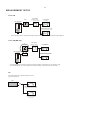
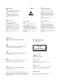
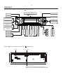
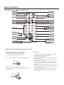
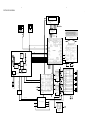
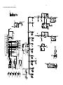
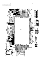
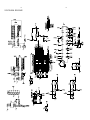
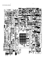
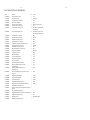
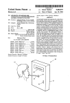
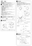
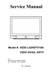
MX-390DVD
Car Audio
Elenberg MX-390DVD
TABLE OF CONTENTS
Page
Technical Specifications ....................................................1-2
Measurement setup ..........................................................1-3
Service Aids, Safety Instruction, etc .......................... 1-4 to 1-5
Preparations & Controls ............................................ 1-6 to 1-8
Maintenance & Troubleshooting ....................................... 1-9
Disassembly Instructions & Service positions ........................ 2
Set Block diagram ............................................................... 3
Set Wiring diagram .............................................................. 4
Key Board ........................................................................... 5
Servo Board ........................................................................ 6
Main Board ......................................................................... 7
Set Mechanical Exploded view & parts list .............................. 8
DE
UNE PU
GR
N
KT
R
1-2
SPECIFICATIONS
General
Components
Power supply:
12V DC(11V-16V)
Test voltage 14.4V, negative ground
Maximum power output:
45Wx4 channels
Continuous power output:
20Wx4 channels (4 10% T.H.D.)
Suitable speaker impedance: 4-8 ohm
Pre-Amp output voltage:
2.0V
Fuse:
15A
Dimensions(WxHxD)
178x50x155mm
Weight:
1.7kg
FM Stereo Radio
Frequency range:
Sensitivity:
Frequency response:
Stereo separation:
Image response ratio:
IF response ratio:
Signal/noise ratio
87.5 - 108.0 MHz
65.0-74.0 MHz (OIRT mode)
8 dB
30Hz-15KHz
30dB(1KHz)
50dB
70dB
55dB
Disc Player
System:
Frequency response:
Signal/noise ratio:
Total harmonic distortion:
Channel separation:
Disc digital audio system
20 Hz - 20KHz
>80 dB
Less than 0.20%(1KHz)
>60 dB
Video signal format system:
PAL/NTSC
Video:
video output:
horizontal nesowtiou:
1
0.2V
500 lines
Note: Specifications and design are subject to change
without notice for product improvements.
Mounting collar
Tappingscrews M5x6 mm
M4x6 mm
Mounting bolt (50 mm)
Wire connector
Removable face plate case
Trim plate
T-key
User manual
Rubber cushion
Remote control
1
4
4
1
1
1
1
2
1
1
1
1-3
MEASUREMENT SETUP
Tuner FM
Bandpass
250Hz-15kHz
DUT
e.g. 7122 707 48001
RF Generator
LF Voltmeter
e.g. PM2534
Ri=50
e.g. PM5326
S/N and distortion meter
e.g. Sound Technology ST1700B
Use a bandpass filter to eliminate hum(50Hz,100Hz) and disturbance from the pilottone(19kHz,38kHz).
Tuner AM (MW,LW)
DUT
Bandpass
250Hz-15kHz
LF Voltmeter
e.g. 7122 707 48001
e.g. PM2534
RF Generator
e.g. PM5326
S/N and distortion meter
Ri=50
e.g. Sound Technology ST1700B
Frame aerial
e.g. 7122 707 89001
To avoid atmospheric interference all AM-measurements have to be carried out in a Faraday' s cage.
Use a bandpass filter ( or at least a high pass filter with 250Hz) to eliminate hum ( 50Hz,100Hz ).
CD
Use Audio Signal Disc SBC429 4822 397 30184
(replaces test disc 3)
DUT
L
R
S/N and distortion meter
e.g. Sound Technology ST1700B
LEVEL METER
e.g. Sennheiser UPM550
with FF-filter
1-4
HANDLING CHIP COMPONENTS
GENERAL
DISMOUNTING
MOUNTING
e.g. A PAIR OF TWEEZERS
VACUUM PISTON
4822 395 10082
SOLDERING
IRON
A
e.g.WELLER
Solder tip PT-H7
A
SOLDERING
IRON
SLODER
0.5-0.8mm
SLODERING
PRESSURE
IRON
SOLDER WICK
4822 321 40042
SLODERING TIME
< 3 secretary / side
e.g. A PAIR OF TWEEZERS
PRESSURE
HEATING
HEATING
SOLDER
B
0.5-0.8mm
SLODERING
IRON
B
CHIP
COMPONENT
SOLDER
SOLDER
COPPER TRACK
P.C.B
SOLDERING
IRON
GLUE
EXAMPLES
CLEANING
C
SOLDER WICK
CORRECT
SOLDERING
IRON
PRECAUTIONS
CORRECT
COPPER TRACK
SOLDERING
IRON
SOLDERING
IRON
NO
SERVICE PACKAGE
CHIP COMPONENT
1-5
GB
NL
ESD
WARNING
Alle IC's en vele andere halfgeleiders zijn
gevoelig voor electrostatische ontladingen
(ESD).
Onzorgvuldig behandelen tijdens reparatie kan
de levensduur drastisch doen verminderen.
Zorg ervoor dat u tijdens reparatie via een
polsband met weerstand verbonden bent met
hetzelfde potentiaal als de massa van het
apparaat .
Houd componenten en hulpmiddelen ook op
ditzelfde potentiaal.
All ICs and many other semi-conductors are
susceptible to electrostatic discharges (ESD).
Careless handling during repair can reduce life
drastically.
When repairing, make sure that you are
connected with the same potential as the mass
of the set via a wrist wrap with resistance.
Keep components and tools also at this
potential.
F
WAARSCHUWING
ATTENTION
I
Tous les IC et beaucoup d'autres
semi-conducteurs sont sensibles aux
decharges statiques(ESD).
Leur longevite pourrait etre considerablement
ecourtee par le fait qu'aucune precaution n'est
prise a leur manipulation.
Lors de reparations,s'assurer de bien etre relie
au meme potentiel que la masse de l'appareil et
enfiler le bracelet serti d'une resistance de
securite.
Veiller a ce que les composants ainsi que les
outils que l'on utilise soient egalement ace
potentiel.
D
AVVERTIMENTO
WARNING
Alle ICs und viele andere Halbleiter sind
empfindich gegenuber elektrostatischen
Entladungen(ESD).
Unsorgfaltige Behandlung im Reparaturfall kan
die Lebensdauer drastisch reduzieren.
Veranlassen Sie,dass Sie im Reparaturfall uber
ein Pulsarmband mit Widerstand verbunden
sind mit dem gleichen Potential wie die Masse
des Gerates.
Bauteile und Hilfsmittel auch auf dieses gleiche
Potential halten.
Tutti IC e parecchi semi-conduttori sono
sensibili alle scariche statiche(ESD).
La loro longevita potrebbe essere fortemente
ridatta in caso di non osservazione della piu
grande cauzione alla loro manipolazione.
Durante le riparazioni occorre quindi essere
collegato allo stesso potenziale che quello della
massa dell'apparecchio tramite un braccialetto
a resistenza.
Assicurarsi che i componenti e anche gli utensili
con quali si lavora siano anche a questo
potenziale.
GB ATTENTION
Safety regulations require that the set be restored to its original
condition and that parts which are identical with those specified,
be used.
Pour votre securite,ces documents
doivent etre utilises par des specialistes agrees,seuls habilites a reparer
votre appareil en panne .
NL
Veiligheidsbepalingen vereisen,dat het apparaat bij reparatie in
zijn oorspronkelijke toestand wordt teruggebracht en dat onderdelen,
identiek aan de gespecificeerde,worden toegepast.
CLASS 1
LASER PRODUCT
3122 110 03420
F
Les normes de securite exigent que I'appareil soit remis a I' etat
d'origine et que soient utilisees les pieces de rechange identiques
a celles specifiees.
GB
Warning!
Invisible laser radiation when open.
Avoid direct exposure to beam.
D
Bei jeder Reparatur sind die geltenden Sicherheitsvorschriften zu
beachten.Der Original zustand des Gerats darf nicht verandert werden;
fur Reparaturen sind Original-Ersatzteile zu verwenden.
S
Varning!
Osynlig laserstralning nar apparaten ar oppnad och sparren
ar urkopplad. Betrakta ej stralen.
SF
Varoitus!
I
Le norme di sicurezza esigono che I'apparecchio venga rimesso
nelle condizioni originali e che siano utilizzati i pezzi di ricambio
identici a quelli specificati.
Avatussa laitteessa ja suojalukituksen ohitettaessa olet alttiina
nakymattomalle laserisateilylle. Ala katso sateeseen!
DK
After servicing and before returning set to customer perform a
leakage current measurement test from all exposed metal parts to
earth ground to assure no shock hazard exist .The leakage current
must not exceed 0.5mA.
Advarse!
Usynlig laserstra ling ved abning nar sikkerhedsafbrydere er
ude af funktion.Undga udsaettelse for straling.
1-6
PREPARATIONS
Wiring Diagram
Video-out
Antenna
(Yellow)
Fuse 15A
Connector
Amplifier
R(Red)
Line-out (Gray)
L(White)
Filter Box
B
ISO Connector
A
Yellow
Black
Blue
Red
Purple Purple/ Gray Gray/
Black
Black
Stripe
Stripe
Right Speaker Right Speaker
(Rear)
(Front)
To car battery(+)
Continuous +12VDC
Ground Lead
Motor/Electric Antenna relay control Lead
Amplifier relay control Lead
Ignition key
+12V DC When ON/ACC
White/ White Green/ Green
Black
Black
Stripe
Stripe
Left Speaker Left Speaker
(Front)
(Rear)
ACC+/red
ANT or AMP controll/blue
Battery 12V(+)/yellow
Ground/black
For some VW/Audi or Opel(Vauxhall)
car models, you may need to modify
wiring of the supplied power cord as
illustrated, or else the memory of the
unit may be lost after you power off.
Contact your authorized car dealer
before installing this unit.
Original wiring
Yellow
Yellow
Red
Red
Modified wiring
Yellow
Yellow
Red
Red
1-7
CONTROLS
Power On : Press any button on the panel except
to turn on the unit.
Press to listen to a preset station
Hold for more than 2 seconds to store station
Remote Sensor
Display switch
Radio preset
Power ON/OFF
DSP
IR
CAR DVD PLAYER MX-390DVD
MENU
Radio tune
RPT
RDM
P/N
R/L
2
3
4
5
6
MON
AMS
Track random play
Tuner
Track repeat play
Loudness
FM stereo/mono
Play / Pause
Top play ( press
more than 2 sec. )
s
Vol Knob
2nd function
Disc play
(when disc is in)
button to open the panel and press
Disc Eject
LO/DX
BAND
AMS
FM1
band switch
1
LOUD
Radio local/distant
SRC
FM2
FM3
OIRT
to eject the disc.
Slot ,Insert the disc
Panel status indication:
When the panel slide down it will light up.
When the panel detached from body it will flash.
Radio auto preset
INT
DVD/VCD Audio Channel L/R/ST
Push the knob for more than 2
seconds to select
EQ/BEEP/VOL LAST
Video System PAL / NTSC
VOL+
PUSH SEL/MENU
Press the
To fast search within
a track/ skip to next
or previous track
Radio preset scan
Rotate the knob to
adjust volume level
Rotate the knob to select
NORMAL/POP/ROCK/CLASSIC)
Beep( ON/OFF)
Vol (LAST/ADJ)
4X45W
VOL-
Intro play(10sec)
Push to select VOL/BAS/
TRE/BAL/FAD, Rotate the
knob to adjust level
Panel Open
1-8
REMOTE CONTROLS
Power On/Off : Press
to turn on/off the unit.
Subtitle(DVD only)
Zoom(DVD only)
Title(DVD only)
Tunre
Power on/off
TITLE
DVD Setup
SETUP
Menu cursor
ZOOM
SRC
SUB.T
REPEAT
A B
ENTER
Enter
Disc Play
(when disc inserted)
REPEAT: Title\chapter\disk\track\index
A-B repeat
Stop / Return
Program
PROG
Digit Area
Audio Mode Select
VOL/BAS/TRE/BAL/FAD
Play / Pause
1
ABC
2
DEF
3
GHI
GOTO
4
JKL
5
MNO
6
PQRS
MENU
PBC
7
TUV
8
WXYZ
9
SPACE
OSD
ON Screen display
0
SEEK+
10+
AUDIO
Audio(DVD only)
VOL -
SEL
VOL+
DISP
ON Panel display
MUTE
SEEK -
BAND
P/N
ANGLE
Angle(DVD only)
+-_
Goto Search
DVD MENU
PBC (for VCD 2.0 or up)
Push more than 2 seconds
to Menu mode
Volume
Mute
Video system PAL/NTSC/AUTO
Radio Tune
Radio band
Track Skip / Seek
Replacing the lithium battery of remote control unit.
* When the operation range of the card remote
control becomes short or no Properly, replace
the lithium battery with a new one. Make sure
the battery polarity replacement is correct.
1. Pull out the battery holder while pressing the stopper.
2. Insert the button-type lithium battery with the (+)
mark facing upward. Insert the battery holder into the
remote control.
(CR 2025)
WARNINGS:
Store the battery in place where children cannot reach.
If a child accidentally swallows the battery,
consult a doctor immediately.
Do not recharge, short, disassemble or heat the battery
or dispose it in a fire.
Doing any of these things may cause the battery to give
off heat,crack or start a fire.
Do not leave the battery with other metallic materials.
Doing this may cause the battery to give off heat, crack
or start a fire.
When throwing away or saving the battery, wrap it in tape
and insulate;otherwise, the battery may start to give off
heat, crack or start a fire.
Do not poke the battery with tweezers or similar tools.
Doing this may cause the battery to give off heat, crack
or start a fire.
1-9
MAINTENANCE AND TROUBLESHOOTING
Maintenance
Clearing disc
When a disc becomes dirty clean it with a cleaning cloth.
Wipe the disc from the center out.
Cleaning the disc lens
After prolonged use, dirt or dust may accumulate at the lens. To ensure good playback quality, clean the disc with Philips CD lens
Cleaner or any commercially available cleaner. Follow the instructions supplied with cleaner.
Cleaning the heads and the Tape Parts
To ensure good playback quality, clean the heads A ,the capstan B ,
and pressure roller C after every 50 hours of tape operation.Used
a cotton swab slightly moistened with cleaning fluid or alcohol.
You can also clean the heads by playing a cleaning tape once.
Troubleshooting
If you suspect something is wrong, immediately switch power off. Immediately stop using it and call the store where you purchased it.
Never try to repair the unit yourself because it is dangerous to do so.
Radio
General
No power or
no sound
Car's engine switch is not on.
Turn your car s key to ACC or ON.
Cable is not correctly connected.
Check connection.
Fuse is burnt. Replace fuse.
Check volume or mute on / off.
If the above solutions cannot help,
press the RESET button.
Station is too far, or signals are too weak.
Select other stations of higher signal level.
Preset station
is reset
Battery cable is not correctly connected.
Connect the battery cable to the
terminal that is always live.
Error Display Messages
Disc
Disc is inserted but
no sound.
Much noise in
broadcasts
Disc is upside down.
Place disc in the correct direction,
and the label side up.
Disc is dirty or damaged
Clean disc or change another disc.
Disc is not CD or contains no MP3 files.
Disc upside down.
Recovery error, check the disc.
Disc sound skips,
tone quality is low.
Sound skips due
Disc is dirty or damaged.
Clean CD or change another CD.
Mounting angle is over 30o.
Adjust mounting angle to less than 30o.
MP3 error, check the disc.
Disc mechanism error
Press
button to eject the disc.
In case that the disc cannot be
ejected by pressing
button,
press the RESET switch and press
the
button again.
If still not ejecting consult your
dealer.
EJ
EJ
to vibration.
Unstable mounting.
Mount the unit securely with the
mounting parts.
EJ
2-1
2-1
DISMANTLING INSTRUCTIONS
1 Pull out the short sheet from main set.
2 Remove top and bottom covers.
4 Remove CD loader
Remove 2 pcs
screw on the
top of loader.
Remove 2 pcs screw
from metal side.
Loosen 8 screws to
remove heatsink &
top cover & bottom
cover.
Remove 6 pcs
screw on the
main board.
3 Loosen 4 pcs screw to remove Front Cabinet.
Remove the 2 pcs
screw to dismantle
the frame.
Remove 2 pcs screw
from front cabinet.
Remove the screw
on the left side of
the cabinet.
Pull out FPC
wire.
Remove the screw
on the right side of
the cabinet.
Remove the 2 pcs
screw to dismantle
the frame.
Remove the
connector from
the mainboard.
2-2
2-2
DISMANTLING INSTRUCTIONS
Service Position A
Service Position B
Service Position C
Service Position D
3
3
SET BLOCK DIAGRAM
Tuner L
T un e r R
Tuner Module
Station Detect/ SIn
te r e o I c o n I n
Local/DX
FM/AM VT
T u n e V ol t a ge
F M OS C
A M OS C
A M/ F M IF
CET-7000
Tuner pll unit
Remote-IR
PLLDO
PLLCE
PLLCL
PLLDI
L C7 2 1 3 0
R ad i o D C 5 V
T un e r P o w e r
IR
LCD Display
KIN0-1
TMP86FS49
LD-SW
CL-SW
OP-SW
1MX16X4BANK
(TSOP1154PIN)
L C D Da t a
DVD-R
SDRAM
D1
D2
CLK
STB
RESET
KV5V-ON
DVD-L
M
LCD Clock
L CD D river
LC 65 23
LCD CE
FLASH MX29LV800T
(TSOP48PIN)
ROM
L
BA6287
MCU
MCU DC 5V
ACC
M ut e
F/L
ST-BY
Vcc1
Vcc2
F/L
R
MUTE
Analog Audio I/P
DVD-PLAYER 4-IN-1 SINGLE CHIP
N.C.
F/L
OUT1+
IN1
L oa d i ng M o t o r -
OUT1-
F/R
F/R
CD-R
PW-GND
Pre-Amp
RC4558
F/R
OUT2+
IN2
OUT2-
CD-L
DVD+5V
PW-GND
R/R
R/R
OUT3-
IN3
PW-GND
R/L
AUX R
Electric Selector & Volume
PT2313
OUT4+
IN4
R/L
AUX-IN
AP1507
AC-GND
S-GND
OUT4PW-GND
G ND
B5V
ACC
Sub Out
Pre-Amp
RC4558
F/R
Line-Output
D9V
G ro u n d
TAB
F/L
D C 1 1 ~ 16 V
Power Supply
SVR
Power Amplifier
TDA7384
Pre-Amp
RC4558
Controlled Power
DVD+9V
D C 1 1~ 1 6 V
R/R
OUT3+
AUX L
D9V
L o a d i ng M o t o r +
E le c t r o n i c V o l u me D a t a
B 5V
GND
A CC
VIDEO-OUT
AM5668
Motor Driver
MIC
E le c t r o ni c V o lu me C l o ck
M C U DC 5V
SPHE8202D
R/L
4
SET WIRING DIAGRAM
4
5-1
5-1
LCD PIN CONNECTION
KEY BOARD
PIN SEGMENT DISPLAY
TABLE OF CONTENTS
LCD Display . . . . . . . . . . . . . . . . . . . . . . . . . . . . . . . 5-1
Circuit Diagram . . . . . . . . . . . . . . . . . . . . . . . . . . . . 5-2
Layout Diagram . . . . . . . . . . . . . . . . . . . . . . . . . . . . 5-3
Electrical Parts List . . . . . . . . . . . . . . . . . . . . . . . . . 5-4
5-2
CIRCUIT DIAGRAM - KEY BOARD
5-2
5-3
LAYOUT DIAGRAM - KEY BOARD
TOP VIEW
LAYOUT DIAGRAM - KEY BOARD
BOTTOM VIEW
5-3
5-4
5-4
ELECTRICAL PARTS LIST - KEY BOARD
Part No.
Description
QTY
83802DVD730EKB000 DVD730 RED KB SMT Assm
143010000259
PCB,KB,DVD730,FR4,1.2mm,165X40.5mm
Location
1
1
143405000069
LED,RED,0603,10mA,2.2V
142400000338
IC,SC75823E,QFP-64-14X14-0.8,SL
24
1
121604000000
RES,0Ω,±5%,1/16W,0603
3
R141,R146,R147
121604000220
RES,22Ω,±5%,1/16W,0603
4
R120~R123
121606000101
RES,100Ω,±5%,1/10W,0805
1
R145
LED101~LED124
IC101
121604000473
RES,47KΩ,±5%,1/16W,0603
3
R124,R138,R139
121606000751
RES,750Ω,±5%,1/10W,0805
4
R134~137
121604000122
RES,1K2Ω,±5%,1/16W,0603
2
R104,R115
121604000182
RES,1K8Ω,±5%,1/16W,0603
2
R106,R117
121604000272
RES,2K7Ω,±5%,1/16W,0603
2
R108,R118
121604000392
RES,3K9Ω,±5%,1/16W,0603
2
R109,R119
121604000562
RES,5K6Ω,±5%,1/16W,0603
1
R110
121604000102
RES,1KΩ,±5%,1/16W,0603
2
R103,R113
121604000152
RES,1K5Ω,±5%,1/16W,0603
2
R105,R116
121604000222
RES,2K2Ω,±5%,1/16W,0603
2
R107,R114
121604000822
RES,8K2Ω,±5%,1/16W,0603
1
R111
121606000471
RES,470Ω,±5%,1/10W,0805
12
R125~131,R150~154
121806000105
CAP,0805,105,50V,Y5V,+80%-20%
3
C102,C103,C104
121803000102
CAP,1nF,±10%,16V,X7R,0603
1
C101
143210000016
TACT SW,KPS-1107YB-130
16
SW101~SW115,SW117
123805000016
14PIN,2.0mm,SOCKET MALE ESTF2-14-01(90 )
1
CON101
141662000008
EN101
o
ENCODER,ECB12,(7X5)(PV)S17
1
143400000009
DVD711,NEGATIVE COLOR,JIC-TB6240N
1
LCD101
142212010002
PHOTO DIODE,IRM2,638AF4,5V/1.1
1
IC102
121490000120
CM203,ZEBRA STRIP
1
6-1
SERVO BOARD
TABLE OF CONTENTS
Circuit Diagram . . . . . . . . . . . . . . . . . . . . . . . . . . . . 6-2
Layout Diagram . . . . . . . . . . . . . . . . . . . . . . . . . . . . 6-3
Electrical Parts List . . . . . . . . . . . . . . . . . . . . . . . . . 6-4
6-1
6-2
CIRCUIT DIAGRAM - SERVO BOARD
6-2
6-3
CIRCUIT DIAGRAM - SERVO BOARD
6-3
6-4
CIRCUIT DIAGRAM - SERVO BOARD
6-4
6-3
LAYOUT DIAGRAM - SERVO BOARD
TOP VIEW
6-3
LAYOUT DIAGRAM - SERVO BOARD
BOTTOM VIEW
6-4
6-4
ELECTRICAL PARTS LIST - SERVO BOARD
Part No.
Description
QTY
83802DVD705ESB010 DVD705E (DVD730E-43A) SB SMT Assm
1
121604000000
11
121604000100
RES,0Ω,±5%,1/16W,0603
RES,10Ω,±5%,1/16W,0603
2
Location
Part No.
121803000330
Description
QTY
CAP,33pF,±5%,50V,NPO,0603
6
Location
BC47 BC51 C79 C80 BC49 BC11
R1 R3 R4 R21 R89 R65 R100
121803010331
CAP,0603,330p,16V,±5%,NPO
1
C73
R103 R104 R201 R30
121803000470
CAP,47pF,±5%,16V,NPO,0603
2
C47 C49
R112 R175
121803000472
CAP,4700pF,±10%,50V,X7R,0603
2
C2 C3
121604000101
RES,100Ω,±5%,1/16W,0603
4
R163 R242 R243 R18
121803000473
CAP,0.047μF,±10%,50V,X7R,0603
1
C69
121604010102
RES,1kΩ,±1%,1/16W,0603
6
R19 R24 R29 R16 R67 R247
121803000681
CAP,680pF,±10%,16V,X7R,0603
5
C62 C63 C64 C65 C52
121604000103
RES,10KΩ,±5%,1/16W,0603
9
121604000332
R17 R20 R92 R93 R94 R244 R38
121803000683
CAP,0.068μF,±10%,50V,X7R,0603
1
C51
R9 R11
121803000821
CAP,0603,820pf,±10%,16V,X7R
1
C71
121845090107
TAN.CAP,100μF,±20%,6.3V,C
5
EC26 EC24 EC25 EC29 EC30
1
L2
RES,3K3Ω,±5%,1/16W,0603
3
R13 R26 R128
121604010122
RES,1K2Ω,±1%,1/16W,0603
1
R122
122000000179
INDUCTOR,1.8μH,±10%,50MA,0805
121604000152
RES,1K5Ω,±5%,1/16W,0603
1
R114
122040000011
CHIP BEAD,0603,1.6X0.8X0.8,800mA,100MHZ,0.6
121604000153
RES,15KΩ,±5%,1/16W,0603
4
R71 R72 R10 R23
10
L9,L10,L12,L13,L18,L19,L22,L26
L29,L16
121604000154
RES,150KΩ,±5%,1/16W,0603
2
R22 R34
122040000061
CHIP BEAD,120Ω,L2XW1.25XT1.25XA0.5,3A,100MHZ,DCR17Ω 3
121604000010
RES,1Ω,±5%,1/16W,0603
1
R32
122040000042
CHIP BEAD,0805,2.0X1.2X0.9X0.5,200mA,100MHZ,0.40Ω
5
L5 L6 L25 L27 L36
121604000223
RES,22KΩ,±5%,1/16W,0603
1
R40(²ÔQ14µ"B""E"¼É)
142206000020
SW DIODE,1N4148,25mA.0.9V,100V,MINI-MELF
7
D8 D9 D10 D2 D3 D4 D6
L20,L28,L38
121604000203
RES,20KΩ,±5%,1/16W,0603
1
R118
142251000001
TR,2N3904(NPN),SOT-23
1
Q33
121604000220
RES,22Ω,±5%,1/16W,0603
2
R69 R70
142245000048
TR,MMBT3906LT1,SOT-23,PNP
2
Q8 Q32
121604000330
RES,0603,33Ω,±5%,1/16W
1
R105
142251000005
TR,2SB1132,SOT-89
2
Q11 Q13
121604000333
RES,33KΩ,±5%,1/16W,0603
1
R124
142400000635
IC,24C02BN,SOP8,ATMEL
1
U6
121604000391
RES,390Ω,±5%,1/16W,0603
1
R113
142400000416
IC,UTC4558,SOP-8,UTC
1
U1
121604000393
RES,39KΩ,±5%,1/16W,0603
1
R127
142400000108
IC,BA6287F,SOP-8,ROMH
1
U3
121604000047
RES,4Ω7,±5%,1/16W,0603
2
121604000472
RES,4K7,±5%,1/16W,0603
12
R87 R97
142400000504
IC,UTC1117-3.3V,SOT-23,UTC
1
U11
R66 R130 R134 R246 R249 R14
142400000505
IC,UTC1117-1.8V,SOT-223,UTC
1
U14
R27 R101~R102 R36 R37 R131
142400000179
IC,IS42S16400A,TSOPII-54,ISSI
1
U5
121604000474
RES,470K,±5%,1/16W,0603
3
R33 R125 R35
142410000024
IC,AM5668S,HSOP28,AMTEK
1
U4
121604000512
RES,5K1,±5%,1/16W,0603
2
R115 R116
142410000108
IC,SPHE8202D,LQFP216,SUNPLUS
1
U2
CN12
121604000750
RES,75,±5%,1/16W,0603
1
R2
123800000018
24PIN,0.5mm,FPC SOCKET SMT TYPE TOP CONNECT TYPE
1
121604000022
RES,22,±5%,1/16W,0603
2
R140 L30
133010000355
PCB,SB,DVD705E,1.2mm,107X109mm(SUNPLUS)
1
121606000330
RES,33,±5%,1/10W,0805
1
R160
121604000562
RES,5K6Ω,±5%,1/16W,0603
3
R12 R25 R129
121618000103
RES,10KΩ4,±5%, 1/16W,0603
1
RN1
121803000272
0603,2n7/16V,X7R,±10%
2
C16 C19
121803000100
CAP,10pF,±1%,50V,NPO,0603
2
C1 C42
121604000473
RES,47KΩ,±5%,1/16W,0603
1
R7
121803000101
CAP,100pF,±5%,50V,NPO,0603
3
C4 C5 C53
142245000015
TR,DTC343TK,SOT-23
1
Q14
121803000102
CAP,1nF,±10%,16V,X7R,0603
9
R126
121803000103
121803000104
CAP,0.01μF,±10%,50V,X7R,0603
CAP,0.1μF,+80%-20%,16V,Y5V,0603
6
64
BC43 BC45 C72 C74 C75 C17 C20,
121604000433
RES,43KΩ,±5%,1/16W,0603
1
C10,C11
144840000023
DVD PLAYER,DL-30H,Foryou
1
C54 BC44 BC18 BC15 C67 C68
143820000149
FFC,20PIN,1.0mm,120mm,E
1
o
o
BC1 BC2 BC3 BC4 BC5 BC7 BC8
121827050227
CAP,220μF,±20%,6.3X7,10V,-55 C--105 C
2
EC46,EC9
BC10 BC12 BC13 BC14 BC16
121830020106
E.CAP,10μF,±20%,4X5.5,16V,85 oC
4
EC2 EC3 EC7 EC8
BC17 BC19 BC20 BC21 BC6 BC22
121830020107
E.CAP,100μF,±20%,6.3X5,16V,105 oC
15
EC1 EC4 EC6 EC32 EC36 EC37
BC23 BC24 BC25 BC26 BC28 BC29
EC39 EC40 EC41 EC42 EC43
BC30 BC31 BC32 BC33 BC34 BC35
EC44 EC53 EC5 EC45
121830040476
E.CAP,47μF,±20%,5X5,16V,105 oC
BC42 BC46 BC48 BC50 BC53 BC54
143405000004
INFRARED RECEIVER,IR928-6C
BC55 BC56 BC57 BC58 BC60 BC61
142820000010
BC36 BC37 BC38 BC39 BC40 BC41
3
2
BC63 BC64 BC66 BC69 BC70,BC74,
143210000004
BC75,BC76,BC77,C43,C45,C48,C57,
127070010965
CRYSTAL,27.000MHz,±20ppm,-30 C~+80 C,CL=18pF,HC-49/US 1
1
DETECT SW,SW111
1
CMV100,LASER WARNING LABEL
C76, C77,C59
142400000040
IC,78L05,TO-92,UTC/ST/KEC
121803040105
CAP,1uF,±10%,25V,X5R,0603
4
C46 C58 C60 C61
123800000022
121803010221
CAP,220pF,±5%,25V,NPO,0603
2
C15 C18
113850000002
121803000152
CAP,1500pF,±10%,50V,X7R,0603
2
C6£C9
121830000226
121803010224
CAP,0.22μF,±10%,25V,X5R,0603
1
C66
142206000004
121803010301
CAP,300pF,±5%,50V,NPO,0603
1
C70
142224000022
o
o
1
EC22 EC38 EC27
D12 D13
XT1
K1
U8
1
CN9
Φ0.5mm,10mm
1
D7
E.CAP,22μF,±20%,4X5,16V,105 oC
1
EC10
2PIN,SOCKET 2.0mm 90
o
REC DIODE,1N4001,1A,1V,50V,DO-41
ZENER DIODE,5V6,1/2W,DO-35
1
D1
1
D11
7-1
MAIN BOARD
TABLE OF CONTENTS
Circuit Diagram . . . . . . . . . . . . . . . . . . . . . . . . . . . . 7-2
Layout Diagram . . . . . . . . . . . . . . . . . . . . . . . 7-3 to 7-4
Electrical Parts List . . . . . . . . . . . . . . . . . . . . 7-5 to 7-6
7-1
7-2
CIRCUIT DIAGRAM - MAIN BOARD
7-2
7-3
LAYOUT DIAGRAM - MAIN BOARD
TOP VIEW
7-3
7-4
LAYOUT DIAGRAM - MAIN BOARD
BOTTOM VIEW
7-4
7-5
7-5
ELECTRICAL PARTS LIST - MAIN BOARD
Part No.
Description
83802DVD705MB002
4X2V ESP FM OIRT RUSOSD(DVD730E-43A)MB SMT Assm
1
R505 R120 R916 R447 R440 R442
83801DVD705MB002
4X2V ESP FM/OIRT RUSOSD(DVD730E-43A)MB A/I Assm
1
R443 R444 R518~R521 R115 R116
QTY
Location
Part No.
Description
QTY
Location
133000020145
MB,DVD703T,94V0,1.6mm,152X194mm
1
121604000104
RES,100K Ω,± 5%,1/16W,0603
5
R909~R913
121640000103
RCF,10K Ω,± 5%,1/8W
5
R123 R823 R512 R513 R902
121604010105
RES,1M Ω,± 1%,1/16W,0603
3
R421 R422 R436
121640000472
RCF,4K7 Ω,± 5%,1/8W
2
R595 R596
121604000154
RES,150K Ω,± 5%,1/16W,0603
4
R522 R523 R524 R525
121640000047
RCF,4 Ω ¸7 ,± 5%,1/8W
1
R535
121604000181
RES,180 Ω,± 5%,1/16W,0603
2
R409 R408
121640000681
RCF,680 Ω,± 5%,1/8W
1
R812
121604000222
RES,2K2 Ω,± 5%,1/16W,0603
8
R105 R423 R418 R417 R416 R415
142203000003
SW DIODE,1N4148,DO-35
6
D806 D805 D501 D401 D402,J126
R419 R915
142206000004
REC DIODE,1N4001,1A,1V,50V,DO-41
1
D803
121604000224
RES,220K Ω,± 5%,1/16W,0603
3
R426 R528 R529
142224000020
ZENER DIODE,5V1,1/2W,DO-35
4
ZD101 ZD405 ZD801 D802
121604000274
RES,270K Ω,± 5%,1/16W,0603
1
R530
142224000001
ZENER DIODE,10V,1/2W,DO-35
1
ZD802
121604000331
RES,330 Ω,± 5%,1/16W,0603
1
R526
113850000039
φ 0.5mm,6mm
113850000038
φ 0.5mm,6.5mm
15
10
J25 J17 J26 J36 J38 J43 J60 J74
121604000332
RES,3K3 Ω,± 5%,1/16W,0603
2
R114 R113
J80 J81 J92 J93 J94 J95 J120
121604000472
RES,4K7 Ω,± 5%,1/16W,0603
4
R510,R511,R493,R537
J7 J8 J9 J28 J88 J89 J105 J116,
121604000473
RES,47K Ω,± 5%,1/16W,0603
11
J125,J133
113850000041
φ 0.5mm,7mm
14
J4 J5 J6 J14 J19 J31 J33 J34 J35
121604000562
RES,5K6 Ω,± 5%,1/16W,0603
5
J39 J45 J47 J62 J124
121604000752
RES,7K5 Ω,± 5%,1/16W,0603
9
113850000043
φ 0.5mm,8mm
9
J12 J16 J37 J48 J75 J91 J96 J103
J117
R434 R605 R606 R611 R612 R534
R122 R814 R494 R495 R806
R506 R507 R108 R508 R509
R803 R601 R602 R610 R613 R603
R604 R618 R619
121604000823
RES,82K Ω,± 5%,1/16W,0603
1
R531
113850000045
φ 0.5mm,9mm
4
J46 J54 J123,J30
121606000000
RES,0 Ω,± 5%,1/10W,0805
3
R906,R413,R420
113850000044
φ 0.5mm,9.5mm
3
J2 J107,J121
121606000010
RES,1 Ω,± 5%,1/10W,0805
1
R117
113850000002
φ 0.5mm,10mm
8
J1 J10 J23 J27 J41 J78 J119 J131
121606000100
RES,10 Ω,± 5%,1/10W,0805
1
R609
113850000001
φ 0.5mm,10.5mm
4
J77 J115 J127 J128
121606000102
RES,1K Ω,± 5%,1/10W,0805
2
R820 R810
113850000004
φ 0.5mm,11mm
9
J15 J22 J24 J29 J32 J52 J57 J87 J104
121606000222
RES,2K2 Ω,± 5%,1/10W,0805
1
R414
113850000006
φ 0.5mm,12mm
10
J44 J49 J50 J53 J58 J100 J102 J109
121606000331
RES,330 Ω,± 5%,1/10W,0805
1
R119
J130 J132
121606000471
RES,470 Ω,± 5%,1/10W,0805
1
R118
113850000005
φ 0.5mm,12.5mm
3
J59 J97 J98
121803000101
CAP,100pF, ± 5%,50V,NPO,0603
2
C106 C114
113850000008
φ 0.5mm,13mm
6
J18 J42 J73 J90,J71,J129
121803000102
CAP,1nF, ± 10%,16V,X7R,0603
3
C126 C505 C506
113850000007
φ 0.5mm,13.5mm
2
J85,J72
121803000103
CAP,0.01 μ F, ± 10%,50V,X7R,0603
113850000012
φ 0.5mm,15mm
2
J56 J79
121803000104
CAP,0.1 μ F,+80%-20%,16V,Y5V,0603
113850000014
φ 0.5mm,16mm
5
J11 J51 J86,J108,J135
C514 C519 C123 C811 C820 C110
113850000013
φ 0.5mm,16.5mm
4
J3 J13 J20 J113
C109 C406 C813 C411 C814 C903
113850000018
φ 0.5mm,18mm
3
J82 J83 J84
C907 C902
4
20
C124 C125 C408 C409
C116 C405 C407 C511 C512 C513
113850000017
φ 0.5mm,18.5mm
1
J76
121604000682
RES,6.8K Ω,± 5%,1/16W,0603
1
R815
113850000019
φ 0.5mm,19.5mm
2
J111 J118
121803000120
CAP,12pF, ± 5%,50V,NPO,0603
2
C403 C404
113850000022
φ 0.5mm,20mm
2
J40 D491
121803000153
CAP,0.015 μ F, ± 10%,50V,X7R,0603
2
C117 C118
113850000011
φ 0.5mm,15.5mm
1
J61
121803000180
CAP,18pF, ± 5%,50V,NPO,0603
2
C402 C401
121648000560
RCF,56 Ω,± 5%,1W
1
R813
121803000223
CAP,0.022 μ F, ± 10%,50V,X7R,0603
4
C101 C115 C112 C105
121648000010
RCF,1 Ω,± 5%,1W
1
R811
121803000330
CAP,33pF, ± 5%,50V,NPO,0603
2
C103 C104
121806000225
CAP,2.2 μ F,+80%,-20%,16V,Y5V,0805
5
C801 C802 C803 C804 C818
121803000332
CAP,3300pF, ± 10%,50V,X7R,0603
2
C119 C120
121604000000
RES,0 Ω,± 5%,1/16W,0603
3
R818 R412 R448
121803000334
CAP,0.33 μ F,+80%-20%,16V,Y5V,0603
2
C508 C509
121604000100
RES,10 Ω,± 5%,1/16W,0603
1
R401
121803000681
CAP,680pF, ± 10%,16V,X7R,0603
4
C805 C806 C807 C808
121604000101
RES,100 Ω,± 5%,1/16W,0603
121604000102
121604000103
RES,1K Ω,± 5%,1/16W,0603
RES,10K Ω,± 5%,1/16W,0603
17
11
38
R121 R404 R405 R410 R403 R402
121806000105
CAP,0805,105,50V,Y5V,+80%-20%
3
C113 C520 C522
R424 R406 R614 R616 R617 R615
142206000020
SW DIODE,1N4148,25mA.0.9V,100V,MINI-MELF
1
D442
R107 R407 R445 R446 R430
142245000015
TR,DTC343TK,SOT-23
4
Q502 Q503 Q504 Q501
R106 R435 R104 R131 R124 R125
142251000001
TR,2N3904(NPN),SOT-23
1
Q505
R126 R127 R908 R433 R901
142245000048
TR,MMBT3906LT1,SOT-23,PNP
1
Q106
R429 R112 R130 R437 R527 R532
142245000028
TR,S8050(NPN),SOT-23
1
Q901
R607 R608 R804 R805 R807 R808
142245000024
TR,KTC8550S(PNP),SOT-23
1
Q107
R438 R821 R439 R809 R102 R111
142245000019
TR,KRC103S,SOT-23
5
Q101 Q802 Q403 Q807 Q804
R103 R129 R425 R128 R441 R533
142245000017
TR,KRA102S(PNP),SOT-23
7
Q102 Q401 Q104 Q683 Q404 Q506
Q405
7-6
7-6
ELECTRICAL PARTS LIST - MAIN BOARD
Part No.
Description
142400000140
IC,CSC2313F,SO-28,YOUDA
1
IC501
142400000416
IC,UTC4558,SOP-8,UTC
2
IC601 IC602
QTY
Location
142400000080
IC,AP1507-5V,TO252-5L,ANACHIP
1
IC901
121604000220
RES,22 Ω,± 5%,1/16W,0603
1
R132
121830000105
E.CAP,1 μ F, ± 20%,4X5,50V,105 oC
5
C809,C121,C122,C521,C523
121830020106
E.CAP,10 μ F, ± 20%,4X5.5,16V,85 oC
1
C410
121830020107
E.CAP,100 μ F, ± 20%,6.3X5,16V,105 oC
9
C817 C823 C111 C102 C504 C819
C816 C822 C606
121830000225
E.CAP,2.2 μ F, ± 20%,4X5,50V,105 oC
12
C507 C510 C515 C516 C517 C518
C527 C528 C607 C608 C609 C610
121830000226
E.CAP,22 μ F, ± 20%,4X5,16V,105 oC
1
121830040476
E.CAP,47 μ F, ± 20%,5X5,16V,105 oC
2
C821 C815
121833000227
E.CAP,220 μ F, ± 20%,6.3X7,10V,85 oC
1
C605
C503
121836000477
E.CAP,470uF, ± 20%,8X11,16V,105 oC
1
C905
121842030225
E.CAP,2.2 μ F, ± 20%,4X5,50V,105 oC ,NON-POLARITY
1
C108
121842000477
E.CAP,470 μ F, ± 20%,6.3X11,6.3V,105 oC
2
C906 C909
121842030338
E.CAP,3300 μ F, ± 20%,13X26,16V,105 oC
1
C810
142206000006
REC DIODE,1N5401,3A,1V,100V,DO-27,HY
1
D801
142257000001
TR,2SB1243TV2Q(PNP),ATV
2
Q803 Q809
142400000218
IC,LM2950-5V,TO-92,HTC
1
IC803
141670000109
GBX050,PTC(RILAIDA)
1
IC802
142400000203
IC,LC72130,DIP24S,SANYO
1
IC101
142400000378
IC,TDA7384,FLEXIWATT25,ST
1
IC801
142400000184
IC,KIA7027,TO-92,KEC
1
IC402
142206000008
REC DIODE,1N5822,3A,0.9V,40V,DO-27
1
D901
CRYSTAL,4.500MHZ, ± 30PPm,-30 oC ~+80 oC ,
1
XT101
1
XT401
1
XT402
142820000031
HC-49/US DIP 30PF
142820000032
CRYSTAL,8.000MHZ, ± 30PPm,-20 oC +70 oC ,
142820000014
CRYSTAL, 32.768MHz, ± 20ppm,-20 oC +70 oC ,CL=12.5pF,
144815000004
TUNER,CET-702CFYA,FM/OIRT
1
TUN101
123805000095
6PIN,2.0mm,WAFER DIP 180 o
1
CON403
HC-49/US DIP 18PF
TUning Fork
123805000017
14PIN,2.0mm,WAFER 90 o
1
CON401
123830010086
CM700,20PIN,PWR/SPK EST-KNT-20-04
1
SK801
143825000190
CONNECTOR,20PIN,1.0mm,CONNECTOR FZC6A-020
1
CON402
141000000319
CM226,BRACKET IC 7386,SECC,T0.8
1
122015000014
CHOKE COIL,470UH,1A, ± 30%,26mm(D)X10mm(L)X14mm(H)
1
(CM206)
1
133000010010
PCB,CB,CM206,94-V0,36x30x1.6mm
122005000010
STAND INDUCTOR DR4X10,150UH, ± 10%,500mA,62X15X6mm 1
L902
122005000017
STAND INDUCTOR,68 μ H, ± 10%, φ 0.4
1
L901
121640000222
RCF,2K2 Ω,± 5%,1/8W
4
R620 R621 R622 R623
124800000025
FUSE,ZH270,15A,SLOW FUSE TYPE
1
8-1
EXPLODED VIEW - MAIN UNIT
8-1
8-2
8-2
MECHANICAL PARTS LIST
Item
1
Assembly Part NO
Description
QTY
Item
83803DVD730EKB000
FRONT PANEL DVD730E-43A
1
52
Assembly Part NO
Description
141218030139
DVD730,PANEL-FRONT BLACK
1
QTY
2
141298000021
CM700,RIM,ABS(BLACK)
1
53
141290000257
CM730,LIGHT GUIDE L,PMMA
1
3
121040000089
SCREW,BTS,BLACK Zinc,M2.6X10.0
2
54
141238000291
CM730,KNOB LO/DX AMS &BAND,PC
1
4
141240050056
CM700,Cabinet,PC
1
55
141238010292
CM730,KNOBNUM,PC
1
5
121040000083
SCREW,BTS,White Ni,M2.6X5
18
56
141290000258
CM730,LIGHT GUIDE R,PMMA
1
6
121025010154
CM700,RIVET GEAR
2
57
141238010297
CM730,KNOBSKIP,PC
1
7
141000010034
CM700,BRACKET-PANEL-RIGHT,SECC,T1.0
1
58
141238020293
CM730,KNOB OPEN,PC
1
8
141200000083
PUSH,CM700,POM
1
59
121035000332
CMV100,SPRING RELEASE NEW,0.3mm,
1
9
121035000135
CM700,EJECT-SPRING,Ø0.60
1
60
121460000027
CAD415,LIGHT SHIELDING SHEET,Tinsel Sheet,T0.15
1
10
121040000185
SCREW,PTP,BLACK Zinc,M2X5
9
61
83802DVD730EKB000
KB ASSM
1
11
133010050415
SK,CM700,FR4,1.2mm,103.3X67.8mm
1
62
121035000136
CM700,L/&R ROTATING SPRING,Ø0.40
2
12
121440000037
CM700E-WASHER,4X0.5
2
63
121025000153
CM700,RIGHT SLIDE BLOCK SHAFT
1
13
141290000241
CM700,LOCKER,POM
1
64
141200000084
CM700,RIGHT-SLIDE,POM
1
14
121035000137
CM700,LOCK SPRING,Ø0.60
1
65
121040000120
SCREW,FTP,BLACK Zinc,M2.0X8
4
15
121025000156
CM700,SHAFT LOCK
1
66
141218010058
CM730,PANEL BACK,ABS
1
16
133000010027
PCB,LB,CM710,1.2mm,94V0,109.5X24mm
1
67
141200000085
CM700,LEFT-SLIDE,POM
1
17
121450000071
CM700S,DUSTPROOF,
1
68
121025000152
CM700,LEFT SLIDE BLOCK SHAFT
1
18
121040000186
SCREW,PTS,Color Znic,M2.0X4
4
69
121490000120
CM203,ZEBRA STRIP
1
19
121200000081
CM226N,DAMPER(N65g),NYLON
1
70
121290000237
CM700,BACK LIGHTING SHEET
1
20
121440000031
CD206,FELT-16-025,Ø3.5XØ1.5X0.25,Graphite fibre
2
71
141290000043
CA-C310,BACKLIGHTGUIDE,PMMA
1
21
141200010082
CM700,GEAR ,POM
1
72
121290010238
CM700,FILTER SHEET
1
22
121025010155
CM700,RIVET PANEL
1
73
143400000009
DVD711,NEGATIVE COLOR,JIC-TB6240N
1
23
141000000063
CM700,BRACKET-DAMR,SECC,T1.0
1
74
141002000002
CAD415,LCD COVER,T0.5
1
24
141237010225
CM700,KNOB-EJECT,PC
1
75
141238000296
CM730,KNOB PWR SYMBOL,PC
1
25
141290000240
CM700,LENS GATE,PC
1
76
141238010445
DVD730,KNOB TA&SRC&LO/DXBLACK,PC
1
26
141000000068
CM700,SIDE STOPR,SECC,T1.0
2
77
121040000086
SCREW,BTS,White Ni,M2.6X7
1
78
121040000075
SCREW,BTS,White Ni,M2.6X10
1
27
141000030069
CAD310,BRACKET-FRONT-U-CD,SECC,T1.0
1
28
121050000005
NUT,White Znic,M3X2.5
2
29
121040000047
SCREW,BM,White Ni,M3X8
2
30
121040000154
SCREW,PA ,White Ni,M2.6X8
2
31
141000000358
CMU706,BRACKET DECK FRONT OF CLC01,SECC,T1.0
1
32
83803DVD705ESB011
SB ASSM
1
33
144840000023
DVD PLAYER,DL-30H,Foryou
1
34
121040000101
Pivot screw M2.6*19
2
35
141000020341
CM701,TOPCOVER,SECC,T0.6
2
36
141000000778
DVD703S,BRACKET REAR DECK,SECC,1.0mm
1
37
121040000069
SCREW,BTS,White Znic,M2.6X3
2
38
121050000003
CMV100,POLE
1
39
121410000026
CMV100,RUBBER
1
40
121040000077
SCREW,BTS,White Ni,M2.6X14
2
41
141000000067
CAD310,SHORT SHEET,SECC,T0.6
1
42
124845000001
ANTENNA,W/GROUND 230mm
1
43
121040000059
SCREW,BTB,White Ni,M2.6X21
2
44
141010020047
CME0CM700,HEATSINK
1
45
121000030076
CAD510,BRACKET-REAR-U,SECC,T1.0
1
46
141000000319
CM226,BRACKET IC 7386,SECC,T0.8
1
47
83803DVD705MB002
MB ASSM
1
48
121040000222
SCREW,FM,BLACK Zinc,M2.6X5
2
49
121290000662
CM725,ISOLATOR SHEET,PC SHEET(T=0.185mm)
1
50
141235020037
CM730,KNOB VOL,PC
1
51
141228010675
LENS,DVD730E-43A,LENS,PMMA(ELENBERG)
1