1
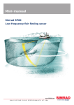
Operator manual
Kongsberg Simrad EA 500
Hydrographic echo sounder
Base version
Kongsberg Simrad EA 500
Hydrographic echo sounder
Operator manual - Base version
850--043661 / AA000 / 1--11
Note
Kongsberg Simrad AS makes every effort to ensure that the information contained within
this document is correct. However, our equipment is continuously being improved and
updated, so we cannot assume liability for any errors which may occur.
Warning
The equipment to which this manual applies must only be used for the purpose for which
it was designed. Improper use or maintenance may cause damage to the equipment or injury
to personnel. The user must be familiar with the contents of the appropriate manuals before
attempting to install, operate or maintain the equipment.
Kongsberg Simrad AS disclaims any responsibility for damage or injury caused by
improper installation, use or maintenance of the equipment.
Copyright
E 2001 Kongsberg Simrad AS
The information contained within this document remains the sole property of Kongsberg
Simrad AS. No part of this document may be copied or reproduced in any form or by any
means, and the information contained within is not to be communicated to a third party,
without the prior written consent of Kongsberg Simrad AS.
KONGSBERG SIMRAD AS
Strandpromenaden 50, P.O.Box 111, N-3191 Horten, Norway
Telephone +47 33 03 40 00 Telefax +47 33 04 44 24
www.kongsberg-simrad.com
Support: hydrographic.support@kongsberg-simrad.com
Sales: horten.sales@kongsberg-simrad.com
Technical emergency number, outside office hours: +47 99 20 38 01
Operator manual
Sections
This book is the Operator manual manual for Base version. It describes how to install the
various units used by the EA 500 system.
The installation of the hull unit is described in a separate manual.
1
System familiarization
2
Operational procedures
3
Command references
4
Maintenance
5
Technical specifications
6
Communication ports
7
Theory of operation
8
Appendices
850-043661 / J
I
Kongsberg Simrad EA 500 / Base version
Remarks
References
Further information about the EA 500 system may be found in the following manuals:
· EA 500 Maintenance manual
· EA 500 Installation manual
The reader
This operator manual is intended to be used by the system operator. He/she should be
experienced in the operation of echo sounder systems, or should have attended a Kongsberg
Simrad training course.
Note
This manual includes sections that may be revised individually. In the event of a revision
to any part of this manual, this “Cover and Contents” section will be replaced.
II
850-043661 / J
Operator manual
Document logistics
Rev
Date
A
01.06.90
B
01.02.91
C
02.02.91
D
31.08.92
E
25.03.93
F
27.05.93
G
08.09.94
H
Written
Checked
Approved
15.03.96
CL
OL
EF
I
10.06.97
CL
EF
EF
J
21.10.01
RBr
ESB
GM
(The original signatures are recorded in the company’s logistic database.)
850-043661 / J
III
Kongsberg Simrad EA 500 / Base version
Comments
Rev
Comments
A
Original edition. Software version 2.40.
B
Software version 2.60.
C
New rear panel, changes in section 1 only.
D
Software version 3.00.
E
Software version 4.00. The layout of the manual has been updated to confirm with
Simrad standards.
F
Corrections and additions throughout the manual, and in the appendices P2265E
Error Messages and P2571E EA 500 DWS.
G
Correction in section ”Introduction”, page 9. Change notice D227.
H
Manual modularized, and updated to reflect new software (version 5.20).
I
Updated to software version 5.30.
J
Manual digitized. System familiarization and Operational procedures converted to
QS with new layout, other documents scanned. No changes to the text.
To assist us in making improvements to the product and to this manual, we would welcome
comments and constructive criticism. Please send all such - in writing or by e-mail - to:
Kongsberg Simrad AS
Documentation Department
P.O.Box 111
N-3191 Horten
Norway
or e-mail:
simrad.documentation@simrad.com
IV
850-043661 / J
Operator manual
Documents
This manual contains the following individual documents:
Cover & Contents . . . . . . . . . . . . 850-043551 . Rev.J
System familiarization . . . . . . . . . 850-130645 . Rev.B
Operational procedures . . . . . . . . 850-130647 . Rev.B
Command references . . . . . . . . . . 850-130495 . Rev.B (Software version 5.3)
Maintenance . . . . . . . . . . . . . . . . . 850-130682 . Rev.B
Technical specifications . . . . . . . . 850-130646 . Rev.A
Communication ports . . . . . . . . . . 850-130683 . Rev.A
Theory of operation . . . . . . . . . . . 850-130659 . Rev.A
Appendices:
Status and error messages . . . . . . 859-043870 . Rev.F
EA 500 Sample / ping interval . . 859-130088 . Rev.B
EA 500 Pinger mode . . . . . . . . . . 859-043976 . Rev.B
EA 500 Multi-channel option . . . 859-130096 . Rev.B
EA 500 DWS System . . . . . . . . . 859-130177 . Rev.C
ASCII - Hex conversion table . . . 859-043869 . Rev.C
850-043661 / J
V
Kongsberg Simrad EA 500 / Base version
Blank page
VI
850-043661 / J
System familiarization
850-130645 / AA000 / 1-11
EA 500
System familiarization
This section of the manual describes the hardware for the echo
sounder system.
850-130645 / B
I
Kongsberg Simrad EA 500 / Base version
Document revisions
Rev
Date
Written by
Checked by
Approved by
A
15.03.96
CL
OL
EF
B
19.10.01
RBr
ESB
GM
C
D
(The original signatures are recorded in the company’s logistic database)
II
850-130645 / B
System familiarization
Table of contents
1
INTRODUCTION . . . . . . . . . . . . . . . . . . . . . . . . . . . . . . . . . . . . . . . . .
1
2
THE SYSTEM UNITS . . . . . . . . . . . . . . . . . . . . . . . . . . . . . . . . . . . . .
2.1 Configuration . . . . . . . . . . . . . . . . . . . . . . . . . . . . . . . . . . . . . . . . . . . .
2.2 Simplified block diagram . . . . . . . . . . . . . . . . . . . . . . . . . . . . . . . . . . .
2.3 Interconnections . . . . . . . . . . . . . . . . . . . . . . . . . . . . . . . . . . . . . . . . . .
2
2
3
4
850-130645 / B
III
Kongsberg Simrad EA 500 / Base version
Document history
(The information on this page is for internal use)
Rev.A
Original issue. Was formerly section 1 of document P2158E.
Rev.B
Document converted to QS. New images pasted in. No changes to the
text.
IV
850-130645 / B
System familiarization
1 INTRODUCTION
Simrad has been in the business of developing special purpose
echo sounders since the 1950’s. Accumulated experience,
combined with the use of the latest technology and circuit design,
has resulted in an echo sounder with greatly improved
performance and with a number of unique features.
The EA 500 is a modular, triple frequency, high-performance
hydrographic echo sounder, with a very accurate reception system
and with independent parallel processing within each of the
frequency channels.
A range of single-beam transducers is available to allow a variety
of frequencies to be used. A dedicated 120 kHz split-beam
transducer is also available for measuring true seabed inclination
in the athwartships direction.
A completely new concept is used in the receiver design, providing
an instantaneous dynamic range of 160 dB. At the same time, the
absolute amplitude measurement accuracy is very high, and this
combined with a low self-noise assures optimum operation under
most conditions. It should be noted that the receivers are never
saturated due to their large instantaneous dynamic range. Hence,
very shallow water surveying becomes a trivial exercise.
The bottom detection algorithm is implemented solely in software,
and separate calculations are performed for each transducer
channel. The algorithm is designed with emphasis on reliability, so
that erroneous depth detections should not be output. Where
uncertainty exists, the algorithm reports unsuccessful detection
rather than an unreliable depth value. This feature is considered
essential in modern survey work where a post-processor is used for
automatic generation of maps, profiles etc.
The EA 500 system includes a display and colour printers showing
echogram and alphanumeric information. The devices are
individually controlled in the sense that echogram range and other
presentation parameters are set independently for each device.
The sounder is equipped with powerful data interfaces for
connection to external postprocessing and data logging systems.
850-130645 / B
1
Kongsberg Simrad EA 500 / Base version
2 THE SYSTEM UNITS
2.1
Configuration
The EA 500 hydrographic echo sounder can be configured for
single, double or triple frequency operation. The various
components included in a triple frequency delivery are shown in
Figure 1. These are:
· Sounder unit
· Display unit (11” LCD, 14” or 20” CRT)
· Transducer(s)
· Colour printer(s)
· RD display
RD DEPTH DISPLAY
SOUNDER UNIT
SIMRAD
PRINTER 1
SIMRAD RD
LCD DISPLAY
HYDROGRAPHIC
ECHO SOUNDER
PRINTER 2
PRINTER 3
TRANSDUCERS
CRT DISPLAY
(CD3016)
Figure 1 EA 500 system modules
A separate transducer is used for each channel, and the operating
frequencies available are in the range 12 to 710 kHz. Single-beam
transducers are available for all frequencies, and a split-beam
transducer is available at 120 kHz for measurement of bottom
slope.
The sounder is typically connected to an 11” LCD display unit or
a 14” colour CRT display unit, both with a built-in joystick. An
optional display type is a 20” rack/console-mounted colour CRT
unit with a small table-mounted keypad unit.
2
850-130645 / B
System familiarization
The printers output individually-controllable colour echograms
and alphanumeric data. The paper width is 210 mm, with 720-dot
resolution across the paper. Transmitter, receiver, processing and
power electronics are all housed in the sounder unit; a rugged and
compact unit with mechanical dimensions compliant to the 19”
rack standard.
2.2
Simplified block diagram
Figure 2 shows the simplified block diagram of the echo sounder
electronics.
TD1
TRANSCEIVER
DIGITIZER
SIGNAL
PROCESSOR
INTERFACE
TD2
TRANSCEIVER
DIGITIZER
SIGNAL
PROCESSOR
CONTROL
PROCESSOR
TD3
TRANSCEIVER
DIGITIZER
SIGNAL
PROCESSOR
DISPLAY/
ETHERNET
SERIAL
PARALLEL
AUX
RGB
ETHERNET
(CD445)
Figure 2 Simplified block diagram
Each transducer channel comprises the following functional
modules:
· A transceiver module containing transmitter and receivers
· A digitizer module performing A/D-conversion and
measurement of electrical phase (applies to split-beam
operation only)
· A dedicated signal processor implementing algorithms for
bottom detection, parameter estimation, echogram generation
etc.
· A control processor. The signal processor(s) communicates via
a common multi-processor bus with the central control
processor. This processor coordinates and synchronizes all
activities inside the sounder and handles communications with
external devices.
850-130645 / B
3
Kongsberg Simrad EA 500 / Base version
· A display/Ethernet module controlled by the control processor;
the ”Display” part generates standard RGB (Red Green Blue)
video signals, and the ”Ethernet” part contains a LAN interface
of the Ethernet type.
· An interface module including RS232 serial interfaces,
Centronics printer interfaces, analogue input signals and output
signal for external transmit synchronization.
2.3
Interconnections
Figure 3 shows the rear panel of the sounder unit. There are five
serial ports of type RS 232:
· Serial port 1 - Remote control and data output.
· Serial port 2 - Annotation input.
· Serial port 3 - Navigation data input/NMEA data output.
· Serial port 4 - Sound velocity probe input.
· Serial port 5 - Simrad RD remote display output.
(CD038 / GIF)
FUSE
SERIAL PORT 1
CENTRONICS 2
CENTRONICS 4
FIFO SAMPLE DATA
FUSE
SERIAL PORT 2
CENTRONICS 1
CENTRONICS 3
ETHERNET
RGB
SERIAL PORT 3
REMOTE CONTROL
SERIAL PORT 4
AUXILIARY
SERIAL PORT 5
TRANSDUCER 1
TRANSDUCER 2
TRANSDUCER 3
All D-connectors are female, except "Ethernet"
Figure 3 Sounder Unit rear connection panel
Printers 1 to 3 are connected to CENTRONICS ports 1 - 3, and the
display/joystick/keypad units are connected to the RGB and the
REMOTE CONTROL connectors. Centronics port 4 is used for
transducer sequence operation. The REMOTE CONTROL
connector comprises parallel lines for cursor control and numeric
input. The AUXILIARY connector includes a differential
analogue input for heave/roll/pitch sensor signals and external
transmission synchronization input/output signals.
4
850-130645 / B
Operational procedures
850-130647 / AA000 / 1-11
EA 500
Operational procedures
This section of the manual describes the man-machine
interface, gives procedures for switching the system on and
off, and includes various operational procedures
850-130647 / B
I
Kongsberg Simrad EA 500 / Base version
Document revisions
Rev
Date
Written by
Checked by
Approved by
A
15.03.96
CL
OL
EF
B
19.10.01
RBr
ESB
GM
C
D
(The original signatures are recorded in the company’s logistic database)
II
850-130647 / B
Operational procedures
Table of contents
1
INTRODUCTION . . . . . . . . . . . . . . . . . . . . . . . . . . . . . . . . . . . . . . . . .
1.1 Overview . . . . . . . . . . . . . . . . . . . . . . . . . . . . . . . . . . . . . . . . . . . . . . . .
1.2 The joystick . . . . . . . . . . . . . . . . . . . . . . . . . . . . . . . . . . . . . . . . . . . . . .
1
1
1
2
THE DISPLAY AND PRINTER LAYOUT . . . . . . . . . . . . . . . . . .
2.1 The display layout . . . . . . . . . . . . . . . . . . . . . . . . . . . . . . . . . . . . . . . . .
2.2 The printer layout . . . . . . . . . . . . . . . . . . . . . . . . . . . . . . . . . . . . . . . . .
2
2
2
3
COLOUR SCALE . . . . . . . . . . . . . . . . . . . . . . . . . . . . . . . . . . . . . . . . . .
6
4
HOW TO SWITCH THE ECHO SOUNDER ON AND OFF . .
7
5
HARD RESET . . . . . . . . . . . . . . . . . . . . . . . . . . . . . . . . . . . . . . . . . . . . .
8
6
OPERATIONAL PROCEDURES . . . . . . . . . . . . . . . . . . . . . . . . . . .
6.1 Introduction . . . . . . . . . . . . . . . . . . . . . . . . . . . . . . . . . . . . . . . . . . . . . .
6.2 How to start the sounder . . . . . . . . . . . . . . . . . . . . . . . . . . . . . . . . . . . .
6.3 How to generate a bottom range echogram
on the display and printer echograms . . . . . . . . . . . . . . . . . . . . . . . . . .
6.4 How to generate scale lines on the display and printer echograms . . .
6.5 How to generate event markers on the display and printer echograms
6.6 How to generate bottom detection line(s) on the display
and printer echograms . . . . . . . . . . . . . . . . . . . . . . . . . . . . . . . . . . . . . .
6.7 How to generate annotations on the printer . . . . . . . . . . . . . . . . . . . . .
6.8 How to generate navigation data on the printer . . . . . . . . . . . . . . . . . .
6.9 How to generate an athwartships bottom slope
line on the display and printer echograms . . . . . . . . . . . . . . . . . . . . . .
9
9
9
850-130647 / B
9
10
10
10
11
11
11
III
Kongsberg Simrad EA 500 / Base version
Document history
(The information on this page is for internal use)
Rev.A
Original issue.
Rev.B
Document converted to QS, images scanned and pasted in. No changes
to the text.
IV
850-130647 / B
Operational procedures
1 INTRODUCTION
1.1
Overview
The display unit normally fitted with the EA 500 echo sounder is
a 14” colour display. This unit has a joystick located towards the
right side of the front panel, below the display, that is used to
control the echo sounder system. Other types of display units may
use ”Arrow” keys in place of a joystick. Pushing an arrow key will
have the same effect as pressing the joystick in the corresponding
direction.
1.2
The joystick
The joystick enables the operator to move a cursor (a reverse video
field) over the desired choices in the menu. Each press up ( ) or
down ( ) on the joystick will move the cursor one line up or down
in the text. A push to the right ( ) will select the particular
parameter, or enter the set value, and return the system to the
submenu. Pushing to the left ( ) will exit the parameter or submenu
without effecting any changes to the values.
A summary of the commands are:
Up - Moves the cursor upwards on the menu or increases value of
parameter
Down - Moves the cursor downwards on the menu or decreases
value of parameter
Right - Selects parameter/enters value, and returns system to
submenu
Left - Exits parameter/submenu without making changes, and
returns system to previous menu level.
850-130647 / B
1
Kongsberg Simrad EA 500 / Base version
2 THE DISPLAY AND PRINTER LAYOUT
2.1
The display layout
The display screen is divided into two main sections; the system
menu is displayed towards the left side, and the graphic field
(echogram) is displayed towards the right.
The following information will be added to the echogram if the
appropriate settings are made in the menu by the operator:
· Bottom range echogram.
· Scale lines.
· Bottom slope line.
· Bottom detection lines.
· Event marker.
Figure 1 Display echogram example
2.2
The printer layout
The printer is able to generate a combination of echograms, lines
and text. Most elements are controlled by parameters located in the
Printer Menu.
The printer echogram may contain all the information of the
display echogram, as well as the additional elements:
2
850-130647 / B
Operational procedures
· Nautical mile marker
· Annotation
· Date and time
· Navigation text
The control of one printer device will have no influence on the
other EA 500 output devices. The colour printer is specified for a
maximum paper speed of 5 lines/sec. It has a graphic resolution of
720 dots, using 12 different colours ranging from blue to red. Black
is used mainly on text and separation lines.
The printer may have up to three independent echograms. The
echogram number is associated with the transceiver number, hence
it will be impossible to print two separate echograms from one
transceiver on the same printer.
A typical layout of a printout is shown in figure 2, while figure 3
shows an echogram with along. slope fixes.
850-130647 / B
3
Kongsberg Simrad EA 500 / Base version
Figure 2 Printer echogram
1 - Annotation text
2 - Annotation date and time
3 - Event marker and number
4 - Navigation data
4
5 - Bottom range
6 - Scale lines
7 - Range
8 - Bottom detection range
9 - Bottom slope
850-130647 / B
Operational procedures
Figure 3 Printout with four along-slope fixes
850-130647 / B
5
Kongsberg Simrad EA 500 / Base version
3 COLOUR SCALE
The colour scale is proportional to the strength of the signals, and
the echo strength is divided into twelve colour categories. The
scale is logarithmic with a 3 dB step between each colour, giving
the colour scale a range of 36 dB from the weakest to the strongest
echo signal.
Display colour Signal strength range
Black/white
From weak signal to --44 dB
Blue
44 to --41 dB
--41 to --38 dB
--38 to 35 dB
--35 to --32 dB
--32 to --29 dB
--29 to --26 dB
--26 to --23 dB
--20 to --17 dB
--17 to --14 dB
--14 to --11 dB
Red
From --11 dB to very strong signal
The colour scale is displayed in the echogram. Note that the above
relationship between colours and dB values is only valid when the
Colour Gain parameter is set to 0 dB.
6
850-130647 / B
Operational procedures
4 HOW TO SWITCH THE ECHO SOUNDER
ON AND OFF
850-130647 / B
1
Switch on the mains power to the Sounder Unit. The On/Off
switch is located on the front side of the unit.
2
Switch on the mains power to the Display Unit. The On/Off
switch is located on the front side of the unit.
3
Switch on the mains power to the printer(s).
4
To switch the echo sounder off, reverse the above procedure.
7
Kongsberg Simrad EA 500 / Base version
5 HARD RESET
Hard reset is achieved by pressing the joystick to the left when
switching on the power. The contents of the RAM will then be
reset, and the sounder will come up with the default settings. Hard
reset is also achieved by pressing the switch behind the hole
marked HR on the Transceiver Unit front when switching on the
power.
8
850-130647 / B
Operational procedures
6 OPERATIONAL PROCEDURES
6.1
Introduction
The echogram movement across the screen and on the printer is
determined by the setting of the Echogram Speed parameter
(Display Menu and Printer Menu) and the Ping Interval (Operation
Menu). The echogram colour presentation is mainly influenced by
Colour Gain and the selected TVG (DISPLAY/Echogram Menu
and PRINTER/Echogram Menu). If the Bottom Range Pres.
command is enabled, 20% of the main echogram is overwritten by
a bottom-referenced echogram. Note that, in the following
procedures, # denotes transceiver number and @ printer number.
6.2
How to start the sounder
The following procedure is the minimum required to instruct the
echo sounder to start pinging, track the bottom and generate an
echogram. In this example it is assumed that only transceiver
channel 1 is used.
1
Select the Transceiver menu.
2
Select the Transceiver-1 menu and check that Mode is set to
Active.
3
Select the Display menu and check that Echogram is set to
1.
4
Select the Bottom detection-1 menu and set Maximum depth
to a value at least as deep as the maximum depth to be
expected.
5
Select the Operator menu, and set Ping mode to Normal.
After a short delay, the sounder will start to ping and an echogram
will begin scrolling from right to left on the display.
6.3
How to generate a bottom range echogram
on the display and printer echograms
850-130647 / B
1
Select the DISPLAY/Echogram-#
PRINTER/Echogram-# Menu).
Menu
(or
the
2
Set the Bot. Range Pres. command to Upper, Bottom or
Lower, depending on where you want the Bottom Range to
be positioned.
3
Set Bottom Range to the desired range of the bottom
echogram.
9
Kongsberg Simrad EA 500 / Base version
4
Set Bottom Range Start to the desired upper start depth of the
bottom echogram.
The bottom range echogram is independent of the main echogram.
It will overwrite 20% of the main echogram. The bottom range
echogram is separated from the main echogram with a solid
boundary line. The bottom range echogram is blanked out if no
bottom detection has been done.
If Sub.Bottom Gain is set above 0.0 dB/m, the bottom range
presentation will feature an excess gain below the detected bottom.
6.4
6.5
How to generate scale lines on the display
and printer echograms
1
Select the DISPLAY/Echogram-#
PRINTER-@/Echogram-# Menu).
Menu
(or
the
2
Select Scale Lines and enter the number of equidistant lines
you want across the echogram.
How to generate event markers on the
display and printer echograms
1
Select the Display Menu (or the Printer Menu).
2
Set Event Marker to On.
The event input may be caused by an external push button or
activated by Event Counter in the Annotation Menu. The event will
result in a red vertical line on the screen and on the printout. The
echogram printout will also include the current event number and
navigation data.
6.6
How to generate bottom detection line(s) on
the display and printer echograms
The bottom detection line may be introduced for easy marking of
the bottom. Each channel has the possibility of displaying the
bottom detection line of other channels.
10
1
Select the DISPLAY/Echogram-#
PRINTER-@/Echogram-# Menu).
Menu
(or
the
2
Set Bot. Det. Line to any of these combinations: 1, 2, 1&2,
3, 1&3, 2&3, 1&2&3.
3
To select which type of sub-bottom presentation you want,
set Presentation to Normal, Wh. Line or Contour.
850-130647 / B
Operational procedures
6.7
6.8
How to generate annotations on the printer
1
Select the PRINTER-@/Echogram-# Menu.
2
Set Annotation to On.
3
Annotation messages received will then be printed on the
echogram.
How to generate navigation data on the
printer
1
Select the PRINTER-@/Echogram-# Menu.
2
Set Navigation Interval to the desired value.
3
The Navigation Interval command sets how often the
incoming navigation telegrams are to be printed on the
echogram.
If, for example, the navigation telegrams are coming in every
second and the Navigation Interval is set to 60, the navigation data
will be printed every minute.
No navigation data will appear on the printer when Navigation
Interval i set to 0.
6.9
How to generate an athwartships bottom
slope line on the display and printer
echograms
The athwartships bottom slope line can only be generated if a
split-beam transducer is used.
To see the bottom slope line on the display, select the Bottom
Detection Menu.
To get a continuous plot of the slope angle on the echogram, select
the
DISPLAY/Echogram-#
Menu
(or
the
PRINTER-@/Echogram-# Menu) and set Bot. Slope Line to On.
The bottom slope information will over-print 20% of the
echogram. The athwartships slope line (green) is positive when the
bottom is shallower on the starboard side. The slope angle value
is plotted as dots in a ±60° scale, with positive values above and
negative values below the 0° line.
850-130647 / B
11
Kongsberg Simrad EA 500 / Base version
Blank page
12
850-130647 / B
Maintenance
850-130682 / AA000 / 1-11
EA 500
Maintenance
This section of the manual describes the maintenance to be
performed by the system operator.
850-130682 / B
I
Kongsberg Simrad EA 500 / Base version
Document revisions
Rev
Date
Written by
Checked by
Approved by
A
15.03.96
CL
OL
EF
B
21.10.01
RBr
ESB
GM
C
D
(The original signatures are recorded in the company’s logistic database)
II
850-130682 / B
Maintenance
Table of contents
1
INTRODUCTION . . . . . . . . . . . . . . . . . . . . . . . . . . . . . . . . . . . . . . . . .
1
2
PREVENTIVE MAINTENANCE ACTIONS . . . . . . . . . . . . . . . . .
1
850-130682 / B
III
Kongsberg Simrad EA 500 / Base version
Document history
(The information on this page is for internal use)
Rev.A
Rev.B
IV
First edition as a combined module for EA 500 and EK 500. Was section 5
of P2158E and P2170E.
Document transferred to QS, now only valid for EA 500. No changes to
the text.
850-130682 / B
Maintenance
1 INTRODUCTION
This chapter describes the preventive maintenance to be performed
by the system operator. For details about corrective maintenance,
refer to the EA/EK/ES 500 Service Manual. For information about
error messages, refer to appendix ”Status and error Messages”.
2 PREVENTIVE MAINTENANCE ACTIONS
The preventive maintenance is very limited. When required, clean
the surfaces of the equipment with a soft, lint-free cloth and a mild
detergent. Keep the fan filter of the sounder unit free from dust and
moisture.
For information about preventive maintenance on the printer, refer
to the printer instruction manual.
850-130682 / B
1
Kongsberg Simrad EA 500 / Base version
Blank page
2
850-130682 / B
Simrad EA 500 / EK 500
STATUS AND ERROR MESSAGES
P2265E / 859-043870 / 4AA005
This section of the manual details the status and error messages that may be
displayed by the echo sounder from time to time. All the possible messages
are listed, and an explanation is given for each.
P2265E/F
1
Status and error messages
Document revisions
Rev
2
Documentation
department
Hardware/Software
Design
Project/Product
Management
Date
Sign
Date
Sign
Date
Sign
E
15.03.96
CL
18.03.96
OL
18.03.96
EF
F
22.05.97
CL
22.05.97
HS
22.05.97
RLN
P2265E/F
Simrad EA 500 / EK 500
List of contents
1 INTRODUCTION . . . . . . . . . . . . . . . . . . . . . . . . . . . . . . . . . . . . . . . . . . .
5
2 GENERAL MESSAGES . . . . . . . . . . . . . . . . . . . . . . . . . . . . . . . . . . . . . .
5
3 SIGNAL PROCESSOR (SP) ERROR MESSAGES . . . . . . . . . . . . . . . . . .
3.1 INTRODUCTION . . . . . . . . . . . . . . . . . . . . . . . . . . . . . . . . . . . . . . .
3.2 LIST OF SIGNAL PROCESSOR ERROR MESSAGES . . . . . . . . . .
7
7
8
P2265E/F
3
Status and error messages
Document history
(The remainder of the information on this page is for Simrad internal use).
Revisions:
Rev. A
Rev. B
Rev. C
Rev. D
Rev. E
Rev. F
4
01.02.91
25.06.92
31.08.92
16.06.93
Original edition.
Minor changes to text.
Document updated, minor changes to text.
Document re-formatted to bring it up to Simrad
standards.
Document re-formatted to bring it up to new Simrad
standards. This document now applies for both EA 500
and EK 500 echo sounders.
New error message included (Serial receive overload).
P2265E/F
Simrad EA 500 / EK 500
1 INTRODUCTION
The 500-series echo sounders may issue alarms, errors, warnings and other
messages to the display and external devices (via serial port or Ethernet).
Note that the # sign indicates the number of the transceiver unit affected
(1/2/3). No number is issued for echo sounders with only one transceiver.
Note that the lists include messages for all the echo sounders in the 500
series.
2 GENERAL MESSAGES
All messages starting with "SP-#" concern signal processor no. # (described in
chapter 3).
Message
Explanation
Bottom lost alarm #
Bottom tracking lost for transceiver-#
Display not ready
Display overload (may occur if system unable to update display
with the current ping rate)
External trigger error
Expected trigger pulse not received
Illegal remote parameter
Parameter value of received remote command out of range or
not recognized
Internal error #
*
Internal error 7
Spurious interrupt (caused by badly formed trigger pulses etc.)
LAN interrupt level fault
*
LAN invalid ind. address
The EA 500 local Ethernet address must be an individual
address, i.e. least significant bit of first byte of address must be
zero
LAN invalid multic. adr.
Invalid EA 500 multicast address
LAN multicast table full
*
LAN no command blocks
May appear while CPU is heavily loaded. Regular appearance
of this message indicates a LAN interface terminator or
hardware problem
LAN no transmit blocks
See above
LAN receive overload
Too much data received from LAN (Local Area Network), data
is lost
LAN socket table full
*
LAN too high priority
*
LAN too long message
*
P2265E/F
5
Status and error messages
Message
Explanation
LAN UDP port busy
*
LAN 82586 init error
Unable to initialize 82586 chip. Possible hardware fault.
Maximum depth alarm #
Bottom of transceiver-# has been detected deeper than the
maximum depth alarm setting
Minimum depth alarm #
Bottom of transceiver-# has been detected shallower than the
minimum depth alarm setting
Navigation telegram error
Invalid navigation telegram received
Ping interval warning
Ping interval time exceeded
Printer-1 not ready
Printer-1 not connected, offline or not ready to print yet
Printer-2 not ready
Printer-2 not connected, offline or not ready to print yet
Printer-3 not ready
Printer-3 not connected, offline or not ready to print yet
Rem. annotation received
Remote annotation has been received successfully
Remote command ignored
Remote control received while remote control disabled
Remote parameter entered
Remote parameter received, decoded and entered successfully
Remote request executed
Remote request has been executed successfully
Serial Com. load warning
Too much data is directed to serial port, data may soon be lost
Serial Com. overload
Too much data is directed to serial port, data is lost
Serial line 1 error
Serial port 1 failure
Serial line 1B error
RD display serial port failure
Serial line 2 error
Serial port 2 failure
Serial line 3 error
Serial port 3 error
Serial line 4 error
Serial port 4 error
Serial receive overload
Unable to receive more data on serial port. Data is lost
Unknown error
*
Unknown remote command
Invalid remote command path/parameter received
Unknown transceiver type
Transceiver hardware switch not recognized
Display processor error
Display/graphic processor (80786) malfunction
Disk error 0
File not found
Replay end of file
Replay data not found
Replay bad data
File create error
File open error
File write error
File close error
6
P2265E/F
Simrad EA 500 / EK 500
Message
Explanation
Disk full
External critical alarm
External critical alarm received
External alarm
External alarm received
Table 1
* = Internal software problem encountered. If this error code is displayed, the
incident should be reported to Simrad.
P2265E/F
7
Status and error messages
3 SIGNAL PROCESSOR (SP) ERROR MESSAGES
3.1 INTRODUCTION
The signal processor will read the control parameters sent by the control
processor before initiating a new ping. The program will then test each
parameter against its legal values. If the parameter is found to be illegal, or
the value does not agree with the other settings, an error message code is
sent to the control processor which will issue the error message.
At power-up the signal processors will never start real pinging until all the
parameters are granted. However, in order to receive new information from
the control processor, it will simulate pinging until no errors occur.
If the error message "SP-# not responding error" is shown on the display, the
signal processor has not answered within a time-out period. This error is
probably caused by one of the following hardware errors:
1
No signal processor PCB present.
2
A new PROM set is not properly inserted in the signal processor (check
carefully).
3
The IC used for signalling is defective (U42 = 8255). This may be
checked by inserting a new 8255.
4
The FIFO system on the digital interface pcb is not working properly.
(If the sounder uses multiple frequencies, try exchanging the digital
interface boards).
5
The signal processor is defective (replace the board, if possible).
8
P2265E/F
Simrad EA 500 / EK 500
3.2 LIST OF SIGNAL PROCESSOR ERROR MESSAGES
Note that the # sign indicates transceiver number (1/2/3) and that all error
messages end with "error".
Error message
Legal values
SP-# angle sensi. error
0 to 100 el./mech.
SP-# bandwidth error
0 to 1
SP-# beamtype error
0 to 1
SP-# btm. min. level error
-80 to 0 dB
SP-# btm. max. depth error
0 to 20000 m
SP-# btm. min. depth error
0 to 1000 m
SP-# damping coeff. error
0 to 300 dB/km
SP-# device data error
See note I
SP-# equ. beam angle error
-100 to -1 dB
SP-# FIFO input error
0 to 1
SP-# frequency error
104 to 106 Hz
SP-# heave conver. error
-10 to 10 V/m
SP-# layer data error
See note III
SP-# noise margin error
0 to 40 dB
SP-# not responding error
See paragraph 3.1
SP-# ping mode error
0 to 3
SP-# pitch conver. error
-10 to 10 V/m
SP-# product type error
0 to 1
SP-# pulse length error
0.02 to 10 ms
SP-# roll conver. error
-10 to 10 V/m
SP-# sample interval error
0.005 to 0.5 m
SP-# sound velocity error
1400 to 1700 m/s
Sample tg error
0 to 1
FIFO tg error
0 to 1
SP-# transceiv. mode error
0 to 3
SP-# transceiver HW error
SP-# transd. depth error
0 to 1000 m
SP-# transd. seq. error
SP-# transd. param. error
See note II
SP-# transd. gain error
1 to 100 dB
SP-# transmit power error
0 to 10 kW
SP-# TS phasedevia. error
0 to 10
SP-# TS min. level error
-100 to 0 dB
P2265E/F
9
Status and error messages
Error message
Legal values
SP-# TS min. length error
0 to 10
SP-# TS max. length error
0 to 10
SP-# TS max. comp. error
0 to 6 dB
Table 2
Note I
SP-# device data error
The appropriate error message in Table 2 will be displayed if one or more of
the following parameters are outside legal limits:
Parameter
Legal values
Bottom echogram dots
0 to 200.
Bottom range
0 to 100 m.
Bottom range start
-100 to 100 m.
Echogram dots
0 to 1000.
Range
0 to 10000 m.
Range start
0 to 10000 m.
Sub-bottom gain
0 to 5 dB/m.
TVG
0 to 2.
Table 3
10
P2265E/F
Simrad EA 500 / EK 500
Note II
SP-# transd. parameter error
The appropriate error message in Table 2 will be displayed if one or more of
the following parameters are outside legal limits:
Parameter
Legal values
Alongship offset angle
-20° to 20° mechanical.
Athwartships offset angle
-20° to 20° mechanical.
Three dB bandwidth
0° to 50° mechanical.
Table 4
Note III
SP-# layer data error
The above error message will occur if one or more of the following parameters
are outside legal limits:
Parameter
Legal values
Layer margin
0 to 10
Layer start
-100 to 20000
Layer stop
-100 to 20000
Layer type
0 to 3
No. of sublayers
1 to 50
Table 5
P2265E/F
11
Status and error messages
12
P2265E/F
Simrad EA 500
EA 500 SAMPLE / PING INTERVAL
P2483E / 859-130088 / 4AA005
This document provides optimum ping intervals for the various frequencies.
P2483E/B
1
Sample interval/ping interval
Document revisions
Rev
Documentation
department
Date
Sign
Hardware/Software
Design
Date
Sign
Project/Product
Management
Date
Sign
B
2
P2483E/B
Simrad EA 500
List of contents
1 INTRODUCTION . . . . . . . . . . . . . . . . . . . . . . . . . . . . . . . . . . . . . . . . . . .
5
2 10 M RANGE . . . . . . . . . . . . . . . . . . . . . . . . . . . . . . . . . . . . . . . . . . . . . . .
5
3 25 M RANGE . . . . . . . . . . . . . . . . . . . . . . . . . . . . . . . . . . . . . . . . . . . . . . .
6
4 50 M RANGE . . . . . . . . . . . . . . . . . . . . . . . . . . . . . . . . . . . . . . . . . . . . . . .
6
P2483E/B
3
Sample interval/ping interval
Document history
(The remainder of the information on this page is for Simrad internal use).
Revisions:
Rev. A 20.06.92
Rev. B
4
First edition.
Document updated to Simrad standards.
P2483E/B
Simrad EA 500
1 INTRODUCTION
This document is a guide to enable you to optimize the ping rate (ping interval).
In earlier software versions, the sample interval has been fixed and dependent
on the frequency. In software versions 3.00 and later, the sample interval has
been made such that it can be selected as required. The tables contain data of
the ping intervals obtained during practical testing with software version 3.0.
The tests were carried out with only one channel active at a time.
2 10 M RANGE
Sample interval (m)
Ping
interval
(second)
38kHz
0.20
0.35
0.10
0.20
0.05
0.03
0.02
0.01
0.13
0.10
0.009
200kHz
0.13
0.10
0.009
0.12
710kHz
0.13
0.10
0.009
0.12
0.005
0.20
With 3 cm sample interval and 10 m main range, a sample interval of 0.10
seconds will give 10 pings per second.
With 2 cm sample interval and 10 m main range, more than 10 pings per second
will be transmitted.
P2483E/B
5
Sample interval/ping interval
3
Sample interval (m)
Ping
interval
(second)
0.20
0.10
0.05
0.03
0.02
0.35
0.21
0.13
0.11
0.13
200kHz
0.13
0.11
0.13
0.21
710kHz
0.13
0.10
0.009
0.21
0.38
0.01
0.005
38kHz
4
Sample interval (m)
Ping
interval
(second)
6
25 M RANGE
0.01
50 M RANGE
0.20
0.10
0.05
0.03
0.02
0.35
0.21
0.13
0.15
0.21
200kHz
0.13
0.15
0.21
0.35
710kHz
0.13
0.15
0.20
0.34
38kHz
0.005
0.68
P2483E/B
Simrad EA 500
EA 500 PINGER MODE
P2372E / 859-043976 / 4AA005
This document describes the 12 kHz listening transducer.
P2372E/B
1
Pinger mode
Document revisions
Rev
Documentation
department
Date
2
A
31.08.92
B
15.03.96
Hardware/Software
Design
Project/Product
Management
Sign
Date
Sign
Date
Sign
CL
18.03.96
OL
18.03.96
EF
P2372E/B
Simrad EA 500
List of contents
1 INTRODUCTION . . . . . . . . . . . . . . . . . . . . . . . . . . . . . . . . . . . . . . . . . . .
5
2 SPECIFICATIONS . . . . . . . . . . . . . . . . . . . . . . . . . . . . . . . . . . . . . . . . . .
2.1 TRANSDUCER . . . . . . . . . . . . . . . . . . . . . . . . . . . . . . . . . . . . . . . . .
2.2 TRANSCEIVER . . . . . . . . . . . . . . . . . . . . . . . . . . . . . . . . . . . . . . . . .
2.3 RANGE PERFORMANCE (12 KHZ) . . . . . . . . . . . . . . . . . . . . . . . . .
6
6
6
6
3 SYSTEM OPERATION . . . . . . . . . . . . . . . . . . . . . . . . . . . . . . . . . . . . . . .
7
4 TIMING STABILITY . . . . . . . . . . . . . . . . . . . . . . . . . . . . . . . . . . . . . . . . .
8
P2372E/B
3
Pinger mode
Document history
(The remainder of the information on this page is for Simrad internal use).
Revisions:
Rev. A 31.08.92
Rev. B 15.03.96
4
Original version.
Document updated and brought up to Simrad's standards.
P2372E/B
Simrad EA 500
1 INTRODUCTION
Simrad has developed a 12 kHz transducer for pinger listening. The transducer
beam width is approximately 50°, and the beam is circular. One or more of the
three channels of the EA 500 can be used for receiving pinger signals. The
frequency of the transceiver channel must correspond with the pinger
frequency.
The EA 500 pinger mode may be used for tracking objects relative to the
surface/bottom or relative to each other.
Note
To avoid damaging the transducer, Simrad strongly recommends
that you install a transceiver board specially made to be used in
conjunction with the 12 kHz pinger mode transducer.
P2372E/B
5
Pinger mode
2 SPECIFICATIONS
2.1 TRANSDUCER
Transducer reg. no: . . . . . . . . . . . . . . . . . . . . . . . . . . . . . . . . . . . . . 312-083741
Frequency: . . . . . . . . . . . . . . . . . . . . . . . . . . . . . . . . . . . . . . . . . . . . . . 12.0 kHz
Transducer beamwidth: . . . . . . . . . . . . . . . . . . . . . . . . . . Approx. 50° circular
Receiver bandwidth: . . . . . . . . . . . . . . . . . . . . . . . . . . . . . . . . . . . . . . . 1.5 kHz
2.2 TRANSCEIVER
Transceiver PCB, 12 kHz reg. no. . . . . . . . . . . . . . . . . . . . . . . . . . . 382-074824
2.3 RANGE PERFORMANCE (12 KHZ)
Assumed ship noise level: . . . . . . . . . . . . . . . . . . . . . . . 50 dB ref. 1µPA, 1 Hz
Assumed signal to noise level: . . . . . . . . . . . . . . . . . . . . . . Better than 10 dB
6
Pinger source level
(rel. 1 µPa)
(dB)
Receive direction
(rel. to vertical)
(°)
Max. range
direct signal
(m)
Max range
bottom reflection
(m)
193
0
14000
7000
185
0
11000
3500
185
±50
5000
800
185
> 70
3000
300
P2372E/B
Simrad EA 500
3 SYSTEM OPERATION
Select the Operation menu and set the Ping interval to a desired value
corresponding to the pinger pulse repetition rate.
Select the desired Transceiver-# menu(s) and set Mode to Passive. This is a
passive listening mode with no transmitter pulses.
The echo sounder can be operated with or without TVG (refer to the Display /
Echogram-# menu). The parameter Colour gain (see the Display / Echogram-#
menu) may be manipulated to obtain echograms that cover the desired signal
strength rate.
P2372E/B
7
Pinger mode
4 TIMING STABILITY
Due to the drift of the two independent clocks, one (the echo sounder and one
in the pinger) the displayed pulse from a constant-depth pinger may drift slowly
over the echogram. The stability of the clock in the echo sounder is better than
50 ppm, corresponding to a drift on the echogram of 4.5 m/min. A similar
contribution can be expected as a result of the clock in the pinger.
8
P2372E/B
Kongsberg Simrad EA 500
Operator manual / Base version
Kongsberg Simrad EA 500
Operator manual / Base version
Kongsberg Simrad EA 500
Operator manual / Base version
Kongsberg Simrad EA 500
Operator manual / Base version