1
TEC Thermal Printer
B-880 SERIES
User's Manual
Original
Apr., 2000
(Revision Apr., 2002)
TABLE OF CONTENTS
OWNER'S MANUAL ............................................. EO1-33017
PRODUCT DESCRIPTION ................................... EO10-33008
MAINTENANCE MANUAL .................................... EO18-33007
Precaution
This service manual is intended for use by service technicians, and designed as a guide for repair
& maintenance. The manual is intended to promote smooth service operations of the product in
the market place. It is not intended for any other purpose such as development or product
specifications. For questions regarding development or product specifications, please contact
the TOSHIBA TEC department in charge.
This manual may be changed or revised without notice. If you find any misprints or omissions,
please contact the TOSHIBA TEC Service Solution Planning Dept. (Ohito) promptly (Facsimile
No. 0558-76-9842).
TEC cannot be held responsible for any trouble which have been caused by misprints or omissions.
The following related manuals contain additional specific information on using B-880 SERIES and
can be referred to for more detailed information available from TOSHIBA TEC sales headquarters.
• Interface/Communication Manual
• Supply Manual
• Specifications
Safety Summary
Personal safety in handling or maintaining the equipment is extremely important. Warnings and
Cautions necessary for safe handling are included in this manual. All warnings and cautions
contained in this manual and written inside or outside of the printer should be read and understood
before handling or maintaining the equipment.
Never modify the machine. Except for the addition of options as specifically provided for in the
service manual, change or modifications to the machine are not approved. Unauthorized changes
or modifications may not comply with your country's safety standards.
Safety Precaution
Electrical equipment is dangerous. Electrical shock from such equipment can cause death. Never
operate electrical equipment unless authorized to do so by a responsible authority.
In emergency work on electrical equipment is authorized, be sure that it is performed in strict
compliance with approved safety regulations.
The following safety precautions will help to ensure proper use of the printer:
• Turn off the printer before 1) opening the top cover for any reason, 2) attaching/detaching
any cable and memory cards, and 3) changing the dip switch setting.
• Disconnect the power cord whenever you are working inside the printer.
• Keep your work environment static free.
TEC Thermal Printer
B-870/880-QQ SERIES
Owner’s Manual
This equipment has been tested and found to comply with the limits for a Class A digital device,
pursuant to Part 15 of the FCC Rules. These limits are designed to provide reasonable protection
against harmful interference when the equipment is operated in a commercial environment. This
equipment generates, uses, and can radiate radio frequency energy and, if not installed and used in
accordance with the instruction manual, may cause harmful interference to radio communications.
Operations of this equipment in a residential area is likely to cause harmful interference in which case
the user will be required to correct the interference at his own expense.
(for USA only)
Changes or modifications not expressly approved by manufacturer for compliance could void the
user's authority to operate the equipment.
"This Class A digital apparatus meets all requirements of the Canadian Interference-Causing
Equipment Regulations."
"Cet appareil numérique de la classe A respecte toutes les exigences du Règlement sur le matériel
brouilleur de Canada."
(for CANADA only)
WARNING!
This is a Class A product. In a domestic environment this product may cause radio interference in
which case the user may be required to take adequate measures.
CAUTION:
Do not touch moving parts. To reduce the risk that fingers, jewelry, clothing, etc., be drawn into the
moving parts, push the switch in the "OFF" position to stop movement.
As an ENERGY STAR® Partner, TOSHIBA TEC has determined that
this product meets the ENERGY STAR® guidelines for energy efficiency.
-- Outline of the International ENERGY STAR® Office Equipment Program -The International ENERGY STAR® Office Equipment Program is an international program that
promotes energy saving through the penetration of energy efficient computers and other office
equipment. The program backs the development and dissemination of products with functions that
effectively reduce energy consumption. It is an open system in which business proprietors can
participate voluntarily. The targeted products are office equipment such as computers, monitors,
printers, facsimiles, copiers, scanners, and multifunction devices. Their standards and logos are
uniform among participating nations.
ENERGY STAR is a U.S. registered mark.
Copyright © 2002
by TOSHIBA TEC CORPORATION
All Rights Reserved
570 Ohito, Ohito-cho, Tagata-gun, Shizuoka-ken, JAPAN
EO1-33017
Safety Summary
Safety Summary
Personal safety in handling or maintaining the equipment is extremely important. Warnings and Cautions
necessary for safe handling are included in this manual. All warnings and cautions contained in this
manual should be read and understood before handling or maintaining the equipment.
Do not attempt to effect repairs or modifications to this equipment. If a fault occurs that cannot be rectified
using the procedures described in this manual, turn off the power, unplug the machine, then contact your
authorized TOSHIBA TEC representative for assistance.
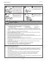
Meanings of Each Symbol
This symbol indicates warning items (including cautions).
Specific warning contents are drawn inside the symbol.
(The symbol on the left indicates a general caution.)
This symbol indicates prohibited actions (prohibited items).
Specific prohibited contents are drawn inside or near the symbol.
(The symbol on the left indicates “no disassembling”.)
This symbol indicates actions which must be performed.
Specific instructions are drawn inside or near the symbol.
(The symbol on the left indicates “disconnect the power cord plug from the outlet”.)
WARNING
Any other than the
specified AC voltage
is prohibited.
This indicates that there is the risk of death or serious injury if the
machines are improperly handled contrary to this indication.
Do not use voltages other than the
voltage (AC) specified on the rating
plate, as this may cause fire or
electric shock.
Prohibited
Do not plug in or unplug the power
cord plug with wet hands as this may
cause electric shock.
Prohibited
If the machines share the same
outlet with any other electrical
appliances which consume large
amounts of power, the voltage will
fluctuate widely each time these
appliances operate. Be sure to
provide an exclusive outlet for the
machine as this may cause the
machines to malfunction.
Prohibited
Do not place metal objects or
water-filled containers such as flower
vases, flower pots or mugs, etc. on
top of the machines. If metal objects
or spilled liquid enter the machines,
this may cause fire or electric
shock.
Prohibited
Do not insert or drop metal,
flammable or other foreign objects into
the machines through the ventilation
slits, as this may cause fire or electric
shock.
Prohibited
Do not scratch, damage or modify
the power cords. Also, do not place
heavy objects on, pull on, or excessively bend the cords, as this may
cause fire or electrical shock.
Disconnect
the plug.
If the machines are dropped or their
cabinets damaged, first turn off the
power switches and disconnect the
power cord plugs from the outlet, and
then contact your authorized
TOSHIBA TEC representative for
assistance. Continued use of the
machine in that condition may cause
fire or electric shock.
Disconnect
the plug.
Continued use of the machines in an
abnormal condition such as when the
machines are producing smoke or
strange smells may cause fire or electric shock. In these cases, immediately turn off the power switches and
disconnect the power cord plugs from
the outlet. Then, contact your authorized TOSHIBA TEC representative for
assistance.
(i)
EO1-33017
Safety Summary
Disconnect
the plug.
Connect a
grounding
wire.
If foreign objects (metal fragments,
water, liquids) enter the machines,
first turn off the power switches and
disconnect the power cord plugs from
the outlet, and then contact your
authorized TOSHIBA TEC representative for assistance. Continued
use of the machine in that condition
may cause fire or electric shock.
Disconnect
the plug.
When unplugging the power cords,
be sure to hold and pull on the plug
portion. Pulling on the cord portion
may cut or expose the internal wires
and cause fire or electric shock.
Ensure that the equipment is
properly grounded. Extension cables
should also be grounded. Fire or
electric shock could occur on
improperly grounded equipment.
No disassembling.
Do not remove covers, repair or
modify the machine by yourself. You
may be injured by high voltage, very
hot parts or sharp edges inside the
machine.
indicates that there is the risk of personal Injury or damage to
CAUTION This
objects if the machines are improperly handled contrary to this indication.
Precautions
The following precautions will help to ensure that this machine will continue to function correctly.
• Try to avoid locations that have the following adverse conditions:
* Temperatures out of the specification
* Direct sunlight
* High humidity
* Shared power source
* Excessive vibration
* Dust/Gas
• The cover should be cleaned by wiping with a dry cloth or a cloth slightly dampened with a mild
detergent solution. NEVER USE THINNER OR ANY OTHER VOLATILE SOLVENT on the plastic
covers.
• USE ONLY TOSHIBA TEC SPECIFIED paper and ribbons.
• DO NOT STORE the paper or ribbons where they might be exposed to direct sunlight, high temperatures, high humidity, dust, or gas.
• Ensure the printer is operated on a level surface.
• Any data stored in the memory of the printer could be lost during a printer fault.
• Try to avoid using this equipment on the same power supply as high voltage equipment or equipment likely to cause mains interference.
• Unplug the machine whenever you are working inside it or cleaning it.
• Keep your work environment static free.
• Do not place heavy objects on top of the machines, as these items may become unbalanced and fall
causing injury.
• Do not block the ventilation slits of the machines, as this will cause heat to build up inside the
machines and may cause fire.
• Do not lean against the machine. It may fall on you and could cause injury.
• Care must be taken not to injure yourself with the printer paper cutter.
• Unplug the machine when it is not used for a long period of time.
Request Regarding Maintenance
•
Utilize our maintenance services.
After purchasing the machine, contact your authorized TOSHIBA TEC representative for assistance
once a year to have the inside of the machine cleaned. Otherwise, dust will build up inside the
machines and may cause a fire or a malfunction. Cleaning is particularly effective before humid
rainy seasons.
•
Our preventive maintenance service performs the periodic checks and other work required to
maintain the quality and performance of the machines, preventing accidents beforehand.
For details, please consult your authorized TOSHIBA TEC representative for assistance.
•
Using insecticides and other chemicals
Do not expose the machines to insecticides or other volatile solvents. This will cause the cabinet or
other parts to deteriorate or cause the paint to peel.
(ii)
EO1-33017
TABLE OF CONTENTS
Page
1.
2.
3.
4.
5.
6.
7.
8.
9.
10.
11.
12.
13.
INTRODUCTION ....................................................................................1- 1
1.1 APPLICABLE MODEL ...................................................................1- 1
1.2 ACCESSORIES .............................................................................1- 1
SPECIFICATIONS .................................................................................2- 1
2.1 PRINTER .......................................................................................2- 1
2.2 OPTION .........................................................................................2- 2
2.3 MEDIA ............................................................................................2- 3
2.4 RIBBON .........................................................................................2- 3
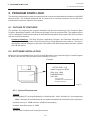
OVERVIEW ............................................................................................3- 1
3.1 FRONT/REAR VIEW......................................................................3- 1
3.2 OPERATION PANEL .....................................................................3- 1
DIP SWITCH FUNCTIONS ....................................................................4- 1
SET UP PROCEDURE ...........................................................................5- 1
5.1 REQUIREMENTS FOR OPERATION ...........................................5- 1
5.2 SETTING UP THE PRINTER.........................................................5- 1
INSTALLATION PROCEDURE .............................................................6- 1
6.1 CONNECTING THE POWER CORD AND CABLES ..................... 6- 1
6.2 HOLDER STAND INSTALLATION ................................................6- 2
LOADING THE RIBBON ........................................................................7- 1
LOADING THE MEDIA ..........................................................................8- 1
INSERTING THE OPTIONAL FLASH MEMORY CARD .......................9- 1
INSERTING THE OPTIONAL PCMCIA CARD .................................... 10- 1
CARE/HANDLING OF THE MEDIA AND RIBBON ............................. 11- 1
GENERAL MAINTENANCE ................................................................12- 1
12.1 CLEANING ...................................................................................12- 1
12.2 UNDER THE MEDIA GUIDES ..................................................... 12- 3
12.3 COVERS AND PANELS .............................................................. 12- 3
12.4 REMOVING JAMMED MEDIA ..................................................... 12- 4
12.5 THRESHOLD SETTING .............................................................. 12- 6
TROUBLESHOOTING .........................................................................13- 1
CAUTION:
1. This manual may not be copied in whole or in part without prior written permission of
TOSHIBA TEC.
2. The contents of this manual may be changed without notification.
3. Please refer to your local Authorized Service representative with regard to any queries
you may have in this manual.
EO1-33017
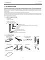
1. INTRODUCTION
1.1 APPLICABLE MODEL
1. INTRODUCTION
Thank you for choosing the TEC B-872/882 Series thermal/transfer printer. This new generation high
performance/quality printer is equipped with the latest hardware including the newly developed high
density (12 dot/mm, 305 dot/inch) edge print head. This will allow very clear print at a maximum speed
of 203.2 mm/sec. (8 inch/sec.). Other standard features include an automatic ribbon saver and external
media supply.
Optional features include a strip mechanism and Cutter mechanism.
This manual contains general set-up and maintenance information and should be read carefully to help
gain maximum performance and life from your printer. For most queries please refer to this manual and
keep it safe for future reference.
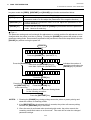
1.1 APPLICABLE MODEL
• B-872-QQ
• B-882-TS10-QQ
• B-882-TS10-QQ-US
Model name description
B - 8 7 2 - T S 1 0 - Q Q
Destination Code
QQ-US: North America block, QQ: Except for QQ-US
Issue mode
S: Batch
Resolution
T: 12 dot/mm (305 dpi)
Thermal direct/Thermal transfer
Printer Type
7: Base Model, 8: Enhanced Model
1.2 ACCESSORIES
Owner's Manual
(EO1-33017)
Power Cord
Print Head Cleaner
(24089500013)
Media Holder
Holder Shaft
Left/Right Side Holder
Holder Base
Thumbscrew
(M-4x6)
Quality control report
1-1
EO1-33017
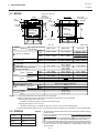
2. SPECIFICATIONS
2.1 PRINTER
2. SPECIFICATIONS
2.1 PRINTER
Model
B-872/882-QQ
Item
Supply voltage
Power consumption
Operating temperature
range
Relative humidity
Print head
Printing methods
Print speeds
Maximum print width
Dispensing modes
Message display
Dimensions
Weight
Available bar-code types
Two-dimensional code
Fonts
Rotations
Standard interfaces
Optional interface
Universal (automatic switching)
85-138 V, 50/60 Hz
187-276 V, 50/60 Hz
Be sure to use a power cord which meets the standard.
3.5 A, 260 W maximum (standby: 360 mA, 20 W maximum)
5˚C ~ 40˚C
25% ~ 85%RH (no condensation)
Thermal print head 12 dots per mm (305 dots per inch)
Thermal direct or Thermal transfer
76.2 mm/sec. (3 inch/sec.), 101.6 mm/sec. (4 inch/sec.),
203.2 mm/sec. (8 inch/sec.) When the media width is 160 mm or less.
213.3 mm (8.40 inches)
Batch (Continuous), Strip (On-demand) and Cut modes
(Both cut and strip modes are available only when their respective modules
are fitted.)
20 characters x 1 line
437 mm (width) x 282 mm (depth) x 395 mm (height)
B-872: 25 kg (without media and ribbon)
B-882: 26 kg (without media and ribbon)
JAN8, JAN13, EAN8, EAN8 + 2 digits, EAN8 + 5 digits
EAN13, EAN13 + 2digits, EAN13 + 5 digits
UPC-E, UPC-E + 2 digits, UPC-E + 5 digits
UPC-A, UPC-A + 2 digits, UPC-A + 5 digits
MSI, ITF, NW-7, CODE39, CODE93, CODE128
EAN128, Industrial 2 to 5, Customer Bar Code, POSTNET, KIX CODE,
RM4SCC (ROYAL MAIL 4STATE CUSTOMER CODE),
Data Matrix, PDF417, QR Code, Maxi Code, Micro PDF417,
CP Code (B-872 only)
Times Roman (6 sizes), Helvetica (6 sizes), Presentation (1 size),
Letter Gothic (1 size), Prestige Elite (2 sizes), Courier (2 sizes),
OCR (2 types), Writable characters (40 types, 2-byte character is available:
B-882 only), Outline font (B-872: 1 type, B-882: 4 types),
Price font (3 types; B-882 only)
0˚, 90˚, 180˚, 270˚
Serial interface (RS-232C)
Parallel interface (Centronics)
Expansion I/O interface
Flash memory card interface (B-872 only)
PCMCIA interface (B-882 only)
∗ Data MatrixTM is a trademark of International Data Matrix, Inc.
PDF417 is a trademark of Symbol Technologies, Inc.
2-1
EO1-33017
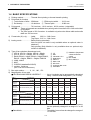
2. SPECIFICATIONS
2.2 OPTION
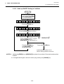
■ Auto Ribbon Saving Mode
Auto ribbon saving function is activated when it is selected by DIP switch (Refer to page 4-1) and
none print area extends for more than 20 mm.
NOTES: 1. To activate ribbon saving function at a speed of 8"/sec., the no print area should extend
more than 25 mm.
2. Depending on the relationship between the outer diameter of rewound ribbon and print
speed, ribbon usage may vary as follows:
Print speed
3"/sec
Ribbon loss
Approx. 5 mm
4"/sec
8"/sec
Approx. 10 mm
Approx. 23 mm
3. For the B-882, contact your authorised TOSHIBA TEC representative to change the
Operation Panel setting.
2.2 OPTION
Option Name
Type
Description
Source
Cutter module
B-4208-QM
A stop and cut swing cutter
Strip module
B-4908-H-QM
This module strips the label from the back- See NOTE 1.
ing paper with the take-up block and strip
block.
D-RAM PC Board
(B-872 only)
FMBC0067801
A 2MB RAM upgrade which enhances the See NOTE 2.
image handling capability of the printer.
Flash memory card
(B-872 only)
PCMCIA interface
board
(B-882 only)
See NOTE 1.
A flash memory card (1MB and 4MB) for See NOTE 3.
storing logos, writable characters and formats.
B-8700-PC-QM
This board enables the following PCMCIA See NOTE 1.
cards to be used.
* LAN card: 3 COM EtherLink®III (recommended)
* ATA card: Conforming to PC card ATA
standard
* Flash memory card: 4MB card (See Page
10-1.)
NOTES:1. Available from your nearest TOSHIBA TEC representative or TOSHIBA TEC Head
Quarters.
2. Available from TOSHIBA TEC Parts Center.
3. When purchasing flash memory card locally, select one having the specifications described
at page 9-1.
2-2
EO1-33017
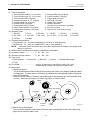
2. SPECIFICATIONS
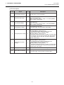
2.3 MEDIA
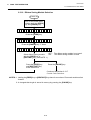
2.3 MEDIA
Label
Stop
position
I
Refer to the following
NOTE 2.
Black Mark
(on reverse side)
Stop
position
Tag paper
I
Tag paper
E
F
Cut
position
Cut
position
J
H
Reference
coordinate 1
Reference
coordinate 1
A
Reference
coordinate 2
Feed direction
G
D
C
G
C
Fig. 2-1
Label dispensing mode
[Unit: mm]
Batch mode
Strip mode
Cut mode
B-872
10.00 ~ 999.0
25.4 ~ 999.0
Label: 38 ~ 999.0
Tag: 25.4 ~ 999.0
B-882
10.00 ~ 1368.0
25.4 ~ 1368.0
Label: 38 ~ 1368.0
Tag: 25.4 ~ 1368.0
B-872
B-882
7.5 ~ 996.5
7.5 ~ 1366.0
22.9 ~ 996.5
22.9 ~ 1366.0
101.6 ~ 225.0
98.6 ~ 222.0
2.5 ~ 20.0
2.5 ~ 10.0
10.0 ~ 213.3
20.9 ~ 320.0
20.9 ~ 1364.0
20.9 ~ 661.3
23.4 ~ 320.0
Item
A : Span of one label/tag
B : Label length
Width including backing paper
Label width
Gap length
Black mark length (Tag paper)
Effective print width
Label
Standard
Max. memory
Effective
print length
Tag
Standard
A
H
B
Reference
coordinate 2
C:
D:
E:
F:
G:
H:
Black Mark
(on reverse side)
2.5 ~ 20.0
B-872
B-882
B-872
B-872
B-882
B-872
5.5 ~ 320.0
5.5 ~ 1364.0
5.5 ~ 661.3
8.0 ~ 320.0
8.0 ~ 1364.0
8.0 ~ 661.3
25.0 ~ 993.0
25.0 ~ 1362.0
6.0 ~ 20.0
23.0 ~ 320.0
23.0 ~ 1364.0
23.0 ~ 661.3
23.4 ~ 320.0
23.4 ~ 1364.0
23.4 ~ 661.3
23.4 ~ 661.3
1.0
Refer to the following NOTE 2.
B-872
160.0
Maximum effective
Standard
length for on the fly
B-882
682.0
issue
Max. memory B-872
330.6
Outer roll diameter
Ø200 Max.
Label
0.13 ~ 0.17
Thickness
Tag
0.10 ~ 0.17
NOTES: 1. The media specification other than above are unchanged.
2. When marking black marks on label rolls, the following requirements must be satisfied.
When the gap length is less than 4 mm:
The black mark length should be longer than the gap length.
When the gap length is 4 mm or more:
The black mark should not overlap the gap for more than 4 mm and the following label.
3. When issuing thermal labels at 8"/sec., the print stop position should be set to a minimum of 1 mm inside the label.
Max. memory
I : Print speed up/slow down area
J : Black mark length (Label)
2.4 RIBBON
Type
Width
Length
Outer diameter
NOTES: 1. “On the fly issue” means that the printer can draw and print without stopping
between labels.
2. To ensure print quality and print head life use only TOSHIBA TEC specified
Spool type
media and ribbons.
3.
When
using the cutter ensure that label length B plus inter label gap length
115 mm ~ 224 mm
E exceeds 35 mm. (i.e. label pitch should be greater than 35 mm.)
300 m
4. Use of rough media for the ribbon saving issue may cause ribbon smudges.
5. To avoid ribbon wrinkles use the ribbon which is wider than media by 5mm
Ø72 mm (max.)
or more. However, too much difference in width between the two may
cause wrinkles.
2-3
EO1-33017
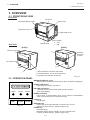
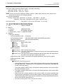
3. OVERVIEW
3.1 FRONT/REAR VIEW
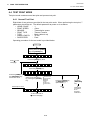
3. OVERVIEW
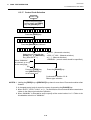
3.1 FRONT/REAR VIEW
Front View
Top Cover
Message Display (LCD)
Head Lever
Operation Panel
Right Side Cover
Power Switch
0: OFF
1: ON
Media Outlet
Rear View
[B-882]
[B-872]
Memory Card Slot
1
PCMCIA
Card Slot
(2 slots)
AC Power Inlet
2
2
3
1
3
1 Serial Interface Connector (RS-232C)
2 Parallel Interface Connector (Centronics)
3 Expansion I/O Interface Connector
Fig. 3-1
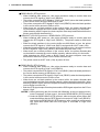
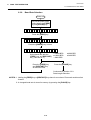
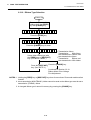
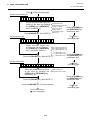
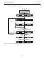
3.2 OPERATION PANEL
MESSAGE DISPLAY (LCD)
When power is turned on and it is ready to print, “ON LINE” is displayed.
POWER LED (Green)
Lights when the power is turned on.
POWER
ON LINE
ERROR
ON-LINE LED (Green)
1) Flashes when communicating with a host computer.
2) On while printing.
ERROR LED (Red)
Lights when a communication error occurs, when the media/ribbon
ends or the printer does not operate correctly.
FEED
RESTART
Fig. 3-2
PAUSE
FEED Key
Feeds paper.
RESTART Key
Resets the printer when paused or when an error occurs.
Used to set the threshold. (Refer to page 12-6)
PAUSE Key
Pauses printing.
Message display shows “PAUSE” and an unprinted count.
Used to set the threshold. (Refer to page 12-6)
3-1
EO1-33017
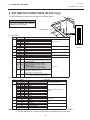
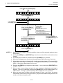
4. DIP SWITCH FUNCTIONS
4. DIP SWITCH FUNCTIONS
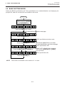
4. DIP SWITCH FUNCTIONS (B-872 only)
The DIP switches are located to the right of the Guide Wheel.
WARNING!
Turn the POWER OFF before
switching the functions.
DIPSW 2
OPEN
1
Guide Wheel
2
3
4
5
6
7
8
DIPSW 1
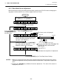
(1) DIP SW 2
No.
1
2
3
4
5
6
OPEN
1
ON/OFF
1
2
OFF
OFF
ON
OFF
OFF
ON
ON
ON
OFF
ON
OFF
ON
OFF
ON
OFF
ON
7
8
OFF
7
ON
2
FUNCTION
3
4
5
6
2400 BPS
4800 BPS
9600 BPS
19200 BPS
1 bit
2 bits
7 bits
8 bits
Without
With
EVEN
ODD
7
Transmission speed
Stop bit length
Data length
Parity check
Parity check (effective when DIP
SW #5 is set to ON.)
XON/XOFF (No XON is output at the power on time.)
(No XOFF is output at the power off time.)
READY/BUSY (DTA)
(No XON is output at the power on time.)
(No XOFF is output at the power off time.)
OFF
READY/BUSY (RTS)
Data protocol
(No XON is output at the power on time.)
(No XOFF is output at the power off time.)
OFF
OFF
ON
XON/XOFF+READY/BUSY
(XON is output at the power on time.)
(XOFF is output at the power off time.)
ON
ON
XON/XOFF (XON is output at the power on time.)
(XOFF is output at the power off time.)
8
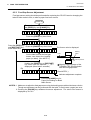
(2) DIP SW 1
No.
1
2
3
4
5
6
7
8
2
OFF
ON
OFF
ON
OFF
ON
OFF
ON
ON/OFF
OFF
ON
3
OFF
OFF
ON
ON
OFF
OFF
ON
ON
OFF
ON
OFF
ON
OFF
ON
OFF
ON
FUNCTION
Without
With
4
OFF
OFF
OFF
OFF
ON
ON
ON
ON
Auto ribbon save function
English
German
French
Dutch
Spanish
Japanese
Italian
Not used
Without
With
Without
With
Fixed type
Movable type
Must be set to OFF
Language to display LCD error
message
Auto media feed after a cut issue
(See page 8-4)
Head up function in cut mode Refer to
Note 2.
Media sensor selection
NOTES: 1. The shaded settings are the factory default settings. “OFF” means “OPEN”.
2. The Dip switch #1-6 functions in accordance with equipment to be used.
4-1
8
Fig. 4-1
EO1-33017
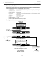
5. SET UP PROCEDURE
5.1 REQUIREMENTS FOR OPERATION
5. SET UP PROCEDURE
5.1 REQUIREMENTS FOR OPERATION
The B-872/882 has the following requirements:
• The host computer must have a serial port or centronics parallel port.
• To communicate with host, either an RS-232C cable or Centronics cable is required.
(1) RS-232C cable .......... 25 pins
(2) Centronics cable ....... 36 pins
• To print the format, create the complete program using the interface/communication manual.
■ Interface Cables
To prevent radiation and reception of electrical noise, the interface cables must meet the following
requirements:
• Fully shielded and fitted with metal or metalised connector housings.
• Kept as short as possible.
• Should not be bundled tightly with power cords.
• Should not be tied to power line conduits.
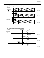
■ RS-232C Cable description
The serial data cable used to connect the printer to the host computer should be one of the following two
types:
NOTE: Use an RS-232C cable with imperial (inch) connector securing screws.
DB-25P
Connector to Printer
DB-9S
Connector to PC
PIN No.
1
2
3
4
5
6
7
8
9
Housing
Signal
N.C.
RXD
TXD
DTR
GND
DSR
RTS
CTS
N.C.
Shield
Signal
Shield
TXD
RXD
RTS
CTS
DSR
GND
DTR
3
2
20
7
6
4
5
TXD
RXD
DSR
GND
DTR
CTS
RTS
Housing
Shield
PIN No.
Signal
3
2
20
7
6
4
5
TXD
RXD
DSR
GND
DTR
CTS
RTS
Fig. 5-1
5.2 SETTING UP THE PRINTER
•
•
•
•
Signal
DB-25P
Connector to Printer
DB-25S
Connector to PC
PIN No.
1
2
3
4
5
6
7
20
PIN No.
Place the printer on a flat, stable surface.
Use a grounded electrical outlet do not use adapter plug.
Be sure there is adequate room around the printer for easy operation and maintenance.
Keep your work environment static free.
5-1
EO1-33017
6. INSTALLATION PROCEDURE
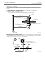
6.1 CONNECTING THE POWER CORD AND CABLES
6. INSTALLATION PROCEDURE
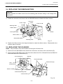
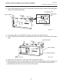
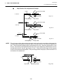
6.1 CONNECTING THE POWER CORD AND CABLES
WARNING!
Turn the POWER SWITCH to OFF before connecting the power cord or cables.
[B-872]
1
[B-882]
1
4
3
2
3
2
4
1 Power Cord
2 Serial I/F Cable (RS-232C)
3 Parallel I/F Cable (Centronics)
4 Expansion I/O Cable
NOTE:
Fig. 6-1
Different cables cannot be used at the same time.
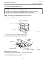
6.2 HOLDER STAND INSTALLATION
Fit the left and right side holders into the dowels of the holder base and fasten the side holders to the
holder base with the thumbscrews.
Thumbscrew
Left Side Holder
Right Side Holder
Holder Base
Dowel
Fig. 6-2
6-1
EO1-33017
7. LOADING THE RIBBON
7. LOADING THE RIBBON
7. LOADING THE RIBBON
WARNING!
1. Do not touch moving parts. To reduce the risk that fingers, jewelry, clothing,
etc., be drawn into the moving parts, push the switch in the “OFF” position to
stop movement.
2. To avoid injury, be careful not to catch or jam your fingers while opening
or closing the cover.
There are two types of media available for printing on, these are standard media and direct thermal media
(a chemically treated surface). DO NOT LOAD a ribbon when using a direct thermal media.
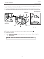
1. Turn the power off and open both the top cover and the right side cover.
2. Set the head lever to the “OPEN” position and release the head lock plate.
Head Lever
Top Cover
Right Side Cover
OPEN
1
2
Head Lock Plate
Fig. 7-1
Head Lever Position
1:
Labels or thin tag paper
2:
Thick tag paper
OPEN: Ribbon/media replacement
3. As Fig. 7-2 shows, unroll and loosen the ribbon a little.
4. Insert the ribbon under the print block so that the ribbon supply end is positioned backside of the
printer.
Ribbon
Ribbon Core
Fig. 7-2
7-1
EO1-33017
7. LOADING THE RIBBON
7. LOADING THE RIBBON
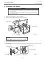
5. Push the ribbon core against the spring guide wheel, align the protrusion of the guide wheel with the
notch of the ribbon core, then set the ribbon.
6. To remove the slack of the ribbon, turn the ribbon core in the direction indicated by the arrow.
7. If the ribbon wrinkles while printing, move the ribbon levers back or forth until the wrinkle is removed.
Spring Guide Wheel
Protrusion
Guide Wheel
STEP 1
STEP 2
Notch
Ribbon Core
Ribbon
Ribbon Lever
Fig. 7-3
NOTE: When removing the ribbon, be careful not to snag the ribbon on the part
.
8. Set the head lock plate.
9. Turn the head lever to the proper position depending on the used media. (Refer to Fig. 7-1)
1: Labels or thin tag paper
2: Thick tag paper
CAUTION:
When using labels ensure that the head lever is set to position 1.
7-2
EO1-33017
8. LOADING THE MEDIA
8. LOADING THE MEDIA
8. LOADING THE MEDIA
WARNING!
1. Do not touch moving parts. To reduce the risk that fingers, jewelry, clothing,
etc., be drawn into the moving parts, push the switch in the “OFF” position to
stop movement.
2. To avoid injury, be careful not to catch or jam your fingers while opening
or closing the cover.
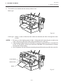
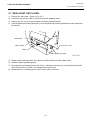
1. Install the holder stand on the rear of the printer.
2. Loosen the screw A and slide the media guides outside.
Media Guides
Holder Stand
Release Lock
Screw A
Fig. 8-1
CAUTION:
DO NOT MOVE the Media Guides using the screw A .
3. Lock the Media Holder securely with the Lock Lever.
4. Pass the Holder Shaft through the Media, then set one of the Media Holders and lock it securely with
the Lock Lever.
Media Holder
Media Holder
Holder Shaft
Holder Shaft
Lock Lever
Media
Lock Lever
8-1
Fig. 8-2
EO1-33017
8. LOADING THE MEDIA
8. LOADING THE MEDIA
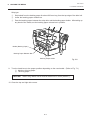
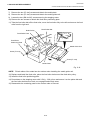
5. Turn the Lock Levers of the Media Holders to the unlock position and readjust the Media position to
the center. Then lock the Media Holders securely with the Lock Levers. Fit the Media Guides to the
Media. Tighten the screw A firmly.
Media Guide
Lock Lever
Media Holder
Media
Media Holder
Media Guide
Screw A
Holder Stand
Notch
Holder Shaft
Bush
Fig. 8-3
NOTE: Set in the bushes of the Holder Shaft into notches of the Holder Stand securely.
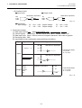
6. The black mark/feed gap sensor is selectable between the fixed type and the movable type by
changing the DIP switch setting on the B-872. For the B-882, contact your authorized TOSHIBA TEC
representative to change the Operation Panel setting. When the fixed type is selected, the black
mark sensor is located at the center of the media and the feed gap sensor is at 10 mm left to the black
mark sensor. The movable sensor can be located anywhere between the left end of the effective
print width and the fixed sensor.
After changing the sensor type, the sensitivity of the sensor must be adjusted. In this case call a
TOSHIBA TEC authorized service representative.
8-2
EO1-33017
8. LOADING THE MEDIA
8. LOADING THE MEDIA
7. Set the black mark/feed gap sensor to the correct position by turning the adjusting knob. Turning
the knob right will move the sensor towards the center of the media while turning left will move it away
from the center of the media.
■ An easy way to set the black mark sensor position
1
2
Pull the media about 500 mm out of the front of the printer, turn the media back on it’s self and
feed it under the print head past the sensor so that the black mark can be seen from above.
Adjust the sensor position to that of the black mark (the upper hole indicates the position of the
black mark sensor).
(Feed Gap Sensor)
Black Mark Sensor
Adjusting Knob
Black Mark
Media
Fig. 8-4
NOTE: Make sure to set the sensor to detect the center of the black mark, otherwise a paper jam
error could occur.
■ Setting the feed gap sensor position
Adjust the sensor to detect on the gap (the lower hole indicates the position of the feed gap
sensor).
(Black Mark Sensor)
Feed Gap Sensor
Adjusting Knob
Media
Fig. 8-5
Media
8-3
EO1-33017
8. LOADING THE MEDIA
8. LOADING THE MEDIA
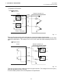
8. The media is now loaded and the sensor position is set.
Batch type:
Media
Fig. 8-6
Cutter type: Where a cutter is fitted load the media as standard and feed it through the cutter
module.
NOTES: 1. Be sure to cut the backing paper of label. Cutting label will cause the glue to stick to the
cutter, which may affect the cutter quality and shorten the cutter life.
2. If the top edge of label winds onto the platen in cut issue, set the DIP SW 1-5 of the B-872
to ON. For the B-882, contact your authorized TOSHIBA TEC representative to change
the Operation Panel setting.
3. Use of tag paper with the thickness exceeding the specified valve may affect the cutter life.
Cutter Module
Media Outlet
Media
Fig. 8-7
8-4
EO1-33017
8. LOADING THE MEDIA
8. LOADING THE MEDIA
Strip type:
1
2
3
Strip labels from the backing paper for about 200-mm long from the top edge of the label roll.
Lower the backing paper release bar.
Pass the backing paper between the strip roller and the backing paper holder. After taking up
any slack of the media, set the backing paper release bar in position.
Media (Backing Paper)
Backing Paper Release Bar
Backing Paper Holder
Fig. 8-8
9. Turn the head lever to the proper position depending on the used media. (Refer to Fig. 7-1)
1: Labels or thin tag paper
2: Thick tag paper
CAUTION:
When using labels ensure that the head lever is set to position 1.
10. Close the top and right side covers.
8-5
EO1-33017
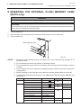
9. INSERTING THE OPTIONAL FLASH MEMORY CARD
9. INSERTING THE OPTIONAL FLASH MEMORY CARD
9. INSERTING THE OPTIONAL FLASH MEMORY CARD
(B-872 only)
WARNING!
Turn the power OFF when inserting or removing the flash memory card.
CAUTION:
To protect memory cards, discharge static electricity from your body by touching the printer rear
cover prior to touching the memory cards.
1. Turn the power off.
2. Insert the flash memory card into the memory card slot on the rear of the printer.
3. Turn the power on.
Flash Memory Card
Fig. 9-1
NOTES: 1. Be sure to protect a flash memory card when not in use in the printer by putting it in it’s
protective cover.
2. Do not subject the card to any shocks or excessive forces.
3. Do not expose the card to extremes of heat by either storing in direct sunlight or close to
a heater.
4. Do not expose the card to excessive humidity by wiping it with a wet cloth or storing it in
a damp place.
5. Before inserting or removing the card, make sure that the power switch is turned off.
6. The following flash cards can be used. (The 1MB-card is read only and the 4MB card can
read/write.)
Device code
Maker code
D0H
1CH
EF-4M-TB CC
88H
B0H
Maxell
EF-4M-TB DC
ADH
04H
Centennial Technologies INC.
FL04M-15-11119-03
INTEL
IMC004FLSA
Simple TECHNOLOGY
STI-FL/4A
Mitsubishi
MF84M1-G7DAT01
PC Card KING MAX
FJN-004M6C
Centennial Technologies INC.
FL04M-20-11138-67
PC Card
Mitsubishi
Capacity
1M Byte
4M Byte
Maker
Type
Maxell
EF-1M-TB AA
Mitsubishi
MF81M1-GBDAT01
Maxell
9-1
01H
A2H
89H
FJP-004M6R
A0H
89H
MF84M1-GMCAV01
AAH
10. INSERTING THE OPTIONAL PCMCIA CARD
EO1-33017
10. INSERTING THE OPTIONAL PCMCIA CARD
10. INSERTING THE OPTIONAL PCMCIA CARD (B-882 only)
WARNING:
Turn the power OFF when inserting or removing the PCMCIA card.
CAUTION:
To protect PCMCIA cards, discharge static electricity from your body by touching the printer rear
cover prior touching the PCMCIA cards.
1. Turn the power off.
2. Insert the PCMCIA card into the card slot at the rear of the printer.
3. Turn the power on.
2
1
PCMCIA Card
Fig. 10-1
NOTES: 1. Be sure to protect a PCMCIA card when not in use in the printer by putting it in its protective
cover.
2. Do not subject the card to any shocks or excessive forces.
3. Do not expose the card to extremes of heat by either storing in direct sunlight or close to a
heater.
4. Do not expose the card to excessive humidity by wiping it with a wet cloth or storing it in a
damp place.
5. Before inserting or removing the card, make sure that the power switch is turned off.
6. The following PCMCIA cards can be used.
Type
Maker
Description
ATA Card
A card conforming to the PC card ATA standard
LAN Card
3 COM
Remarks
Ether Link III 3C589D PC Install into the slot (2) only.
card
(This card installed into the
slot (1) will not work.)
Flash Memory
Card (4 MB)
EF-4M-TB CC
Maxell
EF-4M-TB DC
7. Install the LAN card into the slot (2).
10-1
EO1-33017
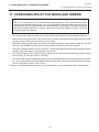
11. CARE/HANDLING OF THE MEDIA AND RIBBON
11. CARE/HANDLING OF THE MEDIA AND RIBBON
11. CARE/HANDLING OF THE MEDIA AND RIBBON
CAUTION:
Be sure to read carefully and understand the Supply Manual. Use only media and ribbon
which meet specified requirements. Use of non-specified media and ribbon may shorten the
head life and result in problems with bar code readability or print quality. All media and ribbon
should be handled with care to avoid any damage to the media, ribbon or printer. Read the
following guideline carefully.
•
Do not store the media and ribbon for longer than the manufactures recommended shelf life.
•
Store media rolls on the flat end, do not store them on the curved sides as this might flatten that side
causing erratic media advance and poor print quality.
•
Store the media in plastic bags and always reseal after opening. Unprotected media can get dirty
and the extra abrasion from the dust and dirt particles will shorten the print head life.
•
Store the media and ribbon in a cool, dry place. Avoid areas where they would be exposed to direct
sunlight, high temperature, high humidity, dust or gas.
•
The thermal paper used for direct thermal printing must not have the specifications which exceed
Na+ 800 ppm, K+ 250 ppm and CL- 500 ppm.
•
Some ink used on pre-printed labels may contain ingredients which shorten the print head’s product
life. Do not use labels pre-printed with ink which contain hard substances such as carbonic calcium
(CaCO3) and kaolin (Al2O3, 2SiO2, 2H2O).
For further information please contact your local distributor or your media and ribbon manufacturer.
11-1
EO1-33017
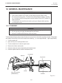
12. GENERAL MAINTENANCE
12.1 CLEANING
12. GENERAL MAINTENANCE
1.
2.
3.
4.
WARNING!
Be cafeful when handling the print head as it becomes very hot.
Care must be taken not to injure yourself with the printer paper cutter.
Do not touch moving parts. To reduce the risk that fingers, jewelry, clothing,
etc., be drawn into the moving parts, push the switch in the “OFF” position to
stop movement.
To avoid injury, be careful not to catch or jam your fingers while opening
or closing the cover.
12.1 CLEANING
WARNING!
1. Be sure to disconnect the power cord prior to performing any maintenance.
2. Do not use any tool that may damage the print head.
3. DO NOT POUR WATER directly onto the printer.
To help retain the high quality and performance of your printer it should be regularly cleaned. The greater
the usage of the printer, the more frequent the cleaning. (i.e. low usage=weekly : high usage=daily).
1. Turn the power off.
2. Open the top cover and right side cover.
3. Turn the head lever to raise the print head.
4. Remove the ribbon and media.
5. Clean the element of print head with print head cleaner.
6. Clean the platen with an alcohol moistened cloth.
Print Head
Element
Print Head
Platen
Print Head Cleaner
(24089500013)
Element
Fig. 12-1
12-1
EO1-33017
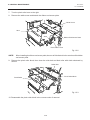
12. GENERAL MAINTENANCE
12.1 CLEANING
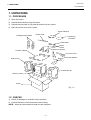
7. Turn the pinch roller lever to the right.
8. Remove the white screw and detach the ribbon end sensor plate.
White Screw
Stud
Stud
Ribbon End Sensor Plate
Pinch Roller Lever
Fig. 12-2
NOTE:
When installing the ribbon end sensor plate, be sure to fit both studs in the notches of the ribbon
end sensor plate.
9. Remove the pinch roller block, then clean the roller belt and feed roller with cloth moistened by
alcohol.
Roller Belt
Pinch Roller Block
Feed Roller
Fig. 12-3
10. Reassemble the pinch roller block in the reverse order of removal.
12-2
EO1-33017
12. GENERAL MAINTENANCE
12.2 UNDER THE MEDIA GUIDES
12.2 UNDER THE MEDIA GUIDES
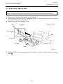
1. Remove the Media Guides.
Screw
Media Guide
Screw
Media Guide
Fig. 12-4
2. Remove the jammed Media.
3. Clean “dust and glue” on the Media Guides with a soft cloth moistened with alcohol.
4. Remount the Media guides using the screws.
NOTE: Be careful NOT TO LOSE the screw.
12.3 COVERS AND PANELS
The covers should be cleaned by wiping with a dry cloth or a cloth slightly dampened with a mild detergent
solution.
NOTE:
Clean printer cover with an electrostatic free cleaner for automated office equipment.
WARNING!
1.
2.
3.
4.
DO NOT POUR WATER directly onto the printer.
DO NOT APPLY cleaner or detergent directly onto any cover or panel.
NEVER USE THINNER OR OTHER VOLATILE SOLVENT on the plastic covers.
DO NOT clean the panel covers or the supply window with alcohol as it may cause them to
discolor, loose their shape or develop structural weakness.
12-3
EO1-33017
12. GENERAL MAINTENANCE
12.4 REMOVING JAMMED MEDIA
12.4 REMOVING JAMMED MEDIA
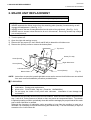
1. Turn the power off.
2. Open the top cover, and right side cover.
3. Turn the head lever to position “OPEN, “ then release the head lock plate.
4. Remove the white screw, unclamp and disconnect the connector of the media guide plate, and then
detach the media guide plate. (See Fig. 12-5.)
5. Remove the ribbon and media.
6. Remove the jammed media. DO NOT USE any sharp implement or tool as these could damage the
printer.
7. Clean the print head and platen, then remove any further dust or foreign substances.
8. Place the portion
of the media guide plate on the media sensor. Secure the media guide plate
with the white screw.
Connector
Media Sensor
Media Guide Plate
Clamp
Media Guide Plate
White Screw
(24741710304)
Fig. 12-5
9. Media jams in the cutter unit can be caused by wear or residual glue from label stock on the cutter.
Do not use none specified media in the cutter. If you get frequent jams in the cutter contact your
Authorized Service representative.
12-4
EO1-33017
12. GENERAL MAINTENANCE
12.4 REMOVING JAMMED MEDIA
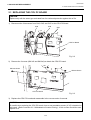
■ Cleaning the Cutter Unit
WARNING!
1. Be sure to turn the power off before cleaning the cutter unit.
2. The cutters are sharp and care should be taken not to injure yourself when cleaning.
1. Loosen two screws and remove the cutter cover.
2. Remove the white screw and media guide.
3. Remove the jammed paper and trash.
4. Clean the cutter with dry cloth.
Screw
White Screw
Media Guide
Fixed Cutter
Cutter Cover
Swing Cutter
Cutter Unit
Fig. 12-7
5. Assembling is reverse order of removal.
■ Cleaning the strip unit
WARNING!
Be sure to turn the power off before cleaning the strip unit.
1. Lower the backing paper release bar to remove the jammed media.
2. Clean the strip roller and backing paper holder with ethyl alcohol.
Strip Roller
Backing Paper Holder
Backing Paper Release Bar
Fig. 12-8
12-5
EO1-33017
12. GENERAL MAINTENANCE
12.5 THRESHOLD SETTING
12.5 THRESHOLD SETTING
For the printer to maintain a constant print position it uses the transmissive sensor to detect the gap
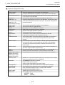
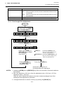
between labels by measuring the amount of light passing through the media. When the media is preprinted, the darker (or more dense) inks can interfere with this process causing paper jam errors. To get
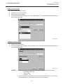
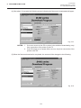
around this problem a minimum threshold can be set for the sensor in the following way.
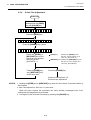
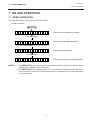
■ Threshold setting procedure
Turn the power ON.
O N
LI NE
(1)
(2)
(3)
The printer is in stand-by.
Load a media roll in the usual way.
Press the [PAUSE] key.
(4)
The printer enters the pause mode.
(5)
(6)
Press and hold the [PAUSE] key for at least 3
seconds in the pause state.
The sensor type is displayed.
(7)
Press the [FEED] key.
(8)
The reflective sensor (black mark sensor) is selected.
(9)
Press the [FEED] key again.
PAUSE
P A US E
PAUSE
T RA NS MIS S IVE
FEED
R EF LE CTI V E
FEED
T RA NS MIS S IVE
PAUSE
T RA NS MIS S IVE
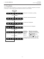
(10) The transmissive sensor (feed gap sensor) is selected.
(11) Press and hold the [PAUSE] key.
(12) The media is advanced until the [PAUSE] key is
released.
(13) Release the [PAUSE] key when more than 1.5 labels
(tags) are advanced.
(Threshold setting is completed by this operation.)
P A US E
RESTART
O N
(14) Press the [RESTART] key.
(15) The printer is in stand-by.
L I NE
Command
O N
LI NE
(16) Send an issue command from the PC to the printer.
NOTES:
1. If the [PAUSE] key is released within 3 seconds whilst in pause state, paper will not feed.
2. Failure to feed more than 1.5 to 2 labels may result in an incorrect threshold setting.
3. While the print head is raised, the [PAUSE] key does not work.
4. Error such as paper end and cutter error are not detected during paper feed.
5. Selecting the transmissive sensor (for pre-printed labels) within software commands allows the printer to
detect the proper print start position correctly even when using pre-printed labels.
6. If the printer continues to print out of position after setting the threshold, adjust the feed gap sensor in the
system mode. Reset the threshold again. Make sure that the transmissive sensor (for pre-printed labels) is
selected in the feed and issue commands.
12-6
EO1-33017
13. TROUBLESHOOTING
13. TROUBLESHOOTING
13. TROUBLESHOOTING
WARNING!
If you cannot solve a problem with the following solutions, do not attempt to repair it yourself. Turn
the power off, unplug the printer, then contact your TOSHIBA TEC representative for assistance.
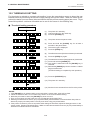
Error Message
PAPER JAM
Solution
Problem
1. The media is not fitted correctly.
∗∗∗∗
1. Re-fit the media correctly.
→ Press the RESTART key.
2. The media path is jammed and does not 2. Remove the cause of the jam and
replace the media correctly.
feed smoothly.
→ Press the RESTART key.
3. The installed media type does not match 3. Turn the power off then on again.
Select the correct sensor.
the selected sensor.
→ Feed the media.
4. The black mark position on the media 4. Adjust the sensor position.
→ Press the RESTART key.
does not match the sensor position.
5. The installed media size is different from 5. Turn the power off then on again.
Set the correct media size.
the programmed size.
→ Feed the media.
6. The feed gap sensor cannot see the 6. Set the threshold (see page 12-6).
Else
difference between the print area and
Turn the power off and call your
the gap.
Authorized Service representative.
HEAD OPEN
Feed or printing has been attempted while Lower the print head or raise the pinch
∗∗∗∗ the print head is raised or the pinch roller roller lever.
→ Press the RESTART key.
lever is depressed.
NO PAPER
The media has run out.
Load new media.
→ Press the RESTART key.
The ribbon has run out.
Load a new ribbon.
→ Press the RESTART key.
∗∗∗∗
NO RIBBON
∗∗∗∗
13-1
EO1-33017
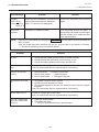
13. TROUBLESHOOTING
13. TROUBLESHOOTING
Error Message
Problem
Solution
EXCESS HEAD The print head is too hot.
TEMP.
HEAD ERROR
Turn the power off and decrease the
print head temperature.
This message is displayed when sending 1. Restart the printing by pressing
the head broken check command ([ESC]
the RESTART key.
HD001 [LF] [NUL]) and the print head has a 2. Replace the print head.
broken element.
RIBBON ERROR There is a fault with the ribbon sensor.
∗∗∗∗
Turn the power off. Contact your
Authorized Service representative.
CUTTER ERROR Media is jammed in the cutter.
∗∗∗∗
Remove the jammed media and
feed the undamaged media through
the cutter.
→ Press the RESTART key.
Else
Turn the power off and contact your
Authorized Service representative.
FLASH WRITE
ERROR
An error has occurred when loading data
onto a flash memory card or ATA card.
1. Turn the power off, re-seat the flash
memory card or ATA card and try
again.
2. Replace the flash memory card
or ATA card and retry.
3. Turn the power off and contact
your Authorized Service
representative.
FORMAT
ERROR
An error has occurred while formatting a
flash memory card or ATA card.
1. Turn the power off, re-seat the flash
memory card or ATA card and try
again.
2. Replace the flash memory card
or ATA card and retry.
3. Turn the power off and contact
your Authorized Service
representative.
FLASH
MEMORY FULL
No more data can be saved in the flash
memory card or ATA card.
Replace the card with a new one
and re-send data.
(In case of flash memory card, only
1MB and 4MB cards can be used.
B-882: 4MB only)
COMMUNICATION A communication error has occurred with Turn the power off then on again or
press the RESTART key.
ERROR
the host.
Check the program data.
→ Call your Authorized Service
representative if necessary.
13-2
EO1-33017
13. TROUBLESHOOTING
13. TROUBLESHOOTING
Error Message
example)
PC001;0A00,
Command error
Solution
Problem
When an error is detected in a command 20 Correct the command and re-send it
again.
bytes of the command are displayed.
(ESC, LF, NUL are not displayed.)
0300, 2, 2
Other Error
Message
NOTE:
Hardware or software trouble.
Turn the power off then on again. If
the problem still exists turn the power
off and contact your Authorized Service representative.
If an error is not cleared by pressing the RESTART key, the power must be switched off
then on again.
After the power has been switched off and on, all print data in the printer is cleared.
**** denotes a remaining count of unprinted labels.
Problem
Solution
No print.
1. Check that the media and the ribbon is loaded correctly.
2. Check whether the print head is set correctly or not.
3. Check the cabling between the printer and the host.
Dots missing in the
print.
Dirty print head. → Clean the print head.
Call your Authorized Service representative if necessary.
Unclear (or blurred)
printing.
1. Dirty print head. → Clean the print head.
2. Bad or faulty ribbon. → Replace ribbon.
3. Poor media quality. → Change media type.
Power does not come
on.
1. Plug power cord into an AC socket.
2. Check the circuit breakers or fuses.
3. Plug another appliance into the AC socket to check if there is power
supplied.
Call your Authorized Service representative if necessary.
Printer does not cut.
Check for a paper jam in the cutter.
Call your Authorized Service representative if necessary.
You see a raised nap
where the media has
been cut.
1. Clean the cutter blades.
2. The blades are worn.
→ Call your Authorized Service representative.
13-3
PRINTED IN JAPAN
EO1-33017
TEC Thermal Printer
B-880 SERIES
Product Description
Document No. EO10-33008
Original
(Revised
Apr., 2000
)
PRINTED IN JAPAN
EO10-33008
TABLE OF CONTENTS
Page
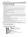
1. OUTLINE OF THE SYSTEM .............................................................................. 1- 1
1.1 FEATURES OF THE B-880 SERIES .......................................................... 1- 1
1.2 DESCRIPTION MODEL NUMBER ............................................................. 1- 1
1.3 OVERVIEW AND DIMENSIONS (APPROXIMATE) ................................... 1- 2
1.4 BASIC SPECIFICATIONS .......................................................................... 1- 3
1.5 ELECTRONICS SPECIFICATION .............................................................. 1- 5
2. SUPPLY SPECIFICATIONS ............................................................................... 2- 1
2.1 MEDIA ......................................................................................................... 2- 1
2.2 RIBBON ...................................................................................................... 2- 2
2.3 CARE AND HANDLING OF THE MEDIA AND RIBBON ............................ 2- 3
3. OPTIONAL KIT ................................................................................................... 3- 1
3.1 CUTTER MODULE : B-4208-QM ................................................................ 3- 1
3.2 STRIP MODULE : B-4908-H-QM ................................................................ 3- 2
3.3 PCMCIA INTERFACE BOARD: B-8700-PC-QM ........................................ 3- 2
CAUTION:
1. This manual may not be copied in whole or in part without prior written permission of
TOSHIBA TEC.
2. The contents of this manual may be changed without notification.
3. Please refer to your local Authorized Service representative with regard to any queries
you may have in this manual.
Copyright © 2000
by TOSHIBA TEC CORPORATION
All Rights Reserved
570 Ohito, Ohito-cho, Tagata-gun, Shizuoka-ken, JAPAN
1. OUTLINE OF THE SYSTEM
EO10-33008
1. 1 FEATURES OF THE B-880 SERIES
1. OUTLINE OF THE SYSTEM
1.1 FEATURES OF THE B-880 SERIES
1) Various bar codes, characters and graphic data can be printed using both thermal transfer and
thermal direct methods.
This printer can also print writable characters and logos at designated coordinates by using a graphic
command.
It not only includes a variety of bar codes, characters and graphic data, but also comes with the
new genaration data code symbol and two-dimensional codes (Data Matrix, PDF417, Maxi
Code, QR Code and PPOST Code) which are replacing bar codes. It can also print using both
thermal transfer and thermal direct methods.
This printer can also print writable characters and logos at designated coordinates using a
graphic command.
2) Since the B-880 accommodates several interfaces such as the RS-232C, Centronics, External I/O
and PCMCIA interface board, it is very versatile.
3) A 16-bit CPU and a Gate Arrey equipped with several peripheral LSIs realizes high system
performance.
4) With the element positioned at the edge of the print head, print quality is improved because the media
passes straight through. No adjustment of media thickness or printing pressure is necessary.
A high dot density of 12 dots/mm produces a clear print and the heat history control system optimizes
applied pulse signal to the head.
5) This printer accommodates a max. format size of 222.0 mm wide, by 1366.0 mm long and a max.
print speed of 203.2 mm/sec.
6) High throughput can be obtained with "on-the-fly" formatting.
7) Since the media is loaded from outside of the printer, the body is smaller, lighter, easier to carry, need
less space and costs less to operate.
8) The metal cover and damper provide a heavy-duty enclosure.
The B-880 has also adopted the automatic switching universal power supply which automatically
adjusts to the voltage of the operating environment.
9) A high-speed ribbon saving function which economizes ribbon usage is available.
10) Optional devices such as a cutter module, Strip module and PCMCIA interface board are available.
NOTE: Every size is written in millimeter (mm) in this manual. To obtain the size in inch, divide by 25.4
Data Matrix is a trade mark of International Data Matix, Inc.
PDF417 is a trade mark of Symbol technologies, Inc.
QR Code is a trade mark of DENSO CORPORATION
Maxi Code is a trade mark of united Parcel Service of America, Inc.
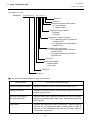
1.2 DESCRIPTION OF MODEL NUMBER
B - 8 8 2 - T S 1 0 - Q Q
Destination Code:
QQ: North America Bloc
QP: Europe Bloc
Issue mode
S: Batch
Resolution
T: 12 dot/mm (305 dpi)
Printing Method: Thermal direct or Thermal transfer
Printer Type
8: Enhanced Model
1-1
1. OUTLINE OF THE SYSTEM
EO10-33008
1. 3 OVERVIEW AND DIMENSIONS (APPROXIMATE)
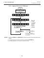
1.3 OVERVIEW AND DIMENSIONS (APPROXIMATE)
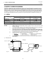
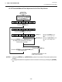
1.3.1
Front View/Rear View
Front View
Message Display (LCD)
Rear View
Serial Interface
Connector (RS-232C)
Top Cover
Head Lever
Operation Panel
Right Side Cover
Media Outlet
Power Switch
0: OFF
1: ON
AC Power Inlet
Parallel Interface
Connector (Centronics) Expansion I/O Interface
Connector
Fig. 1-1
1.3.2
PCMCIA
Card Slot
(2 slots)
Fig. 1-2
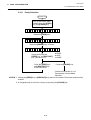
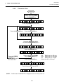
Operation Panel
MESSAGE DISPLAY (LCD)
When power is turned on and it is ready to print, "ON LINE" is
displayed.Also displays messages in each mode of the Diag.
Test Opration.
POWER LED (Green)
POWER
ON LINE
ERROR
Lights when the power is turned on.
ON-LINE LED (Green)
1) Flashes when communicating with a host computer.
2) On while printing.
ERROR LED (Red)
FEED
RESTART PAUSE
Lights when the printer does not operate correctly.
FEED Button
Feeds paper. Used to select options in the Diag. Test Operation
mode and used to fine adjust values in the nagative direction.(Refer
to the Maintenance Manual.)
RESTART Button
Resets the printer when paused or when an error occurs.
Used to set the threshold. (Refer to Owner's Manual)
Used to select option in the Diag. Test Operation mode and used to
fine adjust values in the positive derection. (Refer to the Maintenance Manual.)
PAUSE Button
Pauses printing.
Message display shows "PAUSE" and an unprinted count.
Used to set the thereshold. (Refer to Owner's Manual)
Used as an enter key in the Diag. Test Operation mode.
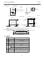
1.3.3
Dimension (Approximate)
Standard
: 437 mm (W) x 282 mm (D) x 395mm (H)
With cutter module : 437 mm (W) x 335 mm (D) x 395 mm (H)
1-2
1. OUTLINE OF THE SYSTEM
EO10-33008
1. 4 BASIC SPECIFICATIONS
1.4 BASIC SPECIFICATIONS
1) Printing method ............... Thermal direct printing or thermal transfer printing
2) Print head (8.4 inches)
1 Total number of dots .. 2560 dots
2 Dot density ................. 12 dots/mm
3 Effctive print width ....... 213.3 mm
4 Thermal pitch .............. 0.083 mm
3) Print speed ...................... 76.2 mm/sec., 101.6 mm/sec., 203.2 mm/sec. (selectable)
NOTES: 1. These print speeds are available when printing ratio is less than 20% of the entire label
or tag paper.
2. The print speed of 203.2 mm/sec. is available only when the ribbon width and media
width are 160 mm max.
4) Format size (W) x (L) ....... Label:
222.0 x 1366.0 max.
Tag Paper: 213.3 x 1364.0 max.
5) Issuing mode ................... Batch printing (standard)
Auto cut (Auto cut mode is only available when an optional cutter is
attached.)
Strip printing (Strip Module is only available when an optional strip
module is attached.)
6) Type of bar code/two dimensional code
1 UPC-A, UPC-A + 2digits, UPS-A + 5digits
2 UPC-E, UPC-E + 2digits, UPC-E +5digits
3 EAN8, EAN8 + 2digits, EAN8 + 5digits,EAN13,
EAN13 + 2digits, EAN13 + 5digits, EAN128
4 JAN8, JAN13
5 NW-7
6 CODE39 (standard/full ASCII)
7 CODE93, CODE128
8
9
0
A
B
C
D
E
F
(auto code switch with/without)
G
ITF
MSI
Industrial 2 of 5
H
Data Matrix
I
PDF417
Maxi Code
QR Code
Customer Bar Code
POSTNET
RM4SCC (Royal Mail
4 State Customer
Code)
KIX CODE
Micro PDF417
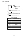
7) Bar code rotation ........... 0 , 90 , 180 , 270
8) Magnification of bar code
■ UPC/EAN/JAN/CODE93/128/PDF417 ............ Up to 6 modules can be automatically calculated
using 1-module width designation (1 to 15 dots).
Dots/Module
2
3
4
5
6
7
8
Min. Module Width (mm)
–
0.25
0.33
0.42
0.50
0.58
0.66
Magnification (times)
–
0.76
1
1.27
1.52
1.76
2
0.166
0.25
0.33
0.42
0.50
0.58
0.66
9
10
11
12
13
14
15
Min. Module Width (mm)
–
–
–
–
–
–
–
Magnification (times)
–
–
–
–
–
–
–
0.747
0.83
0.91
1.00
1.08
1.16
1.25
Bar code
UPC-A/E
EAN8/13
JAN8/13
CODE93
EAN128
CODE128
PDF417
Min.Module Width (mm)
Dots/Module
Bar code
UPC-A/E
EAN8/13
JAN8/13
CODE93
EAN128
CODE128
PDF417
Min.Module Width (mm)
■ NW-7/CODE39/ITF/MSI/Industrial 2 of 5 ........ The width of narrow bars, wide bars and spaces
can be optionally changed in a range of 1 to 99
dots.
■ Data Matrix ...................................................... The width of one cell can be changed in a range of
1 to 99 dots.
1-3
1. OUTLINE OF THE SYSTEM
EO10-33008
1. 4 BASIC SPECIFICATIONS
9) Type of characters
1 Times Roman medium (12, 15 point)
2 Times Roman bold (15, 18, 21 point)
3 Times Roman Italic (18 point)
4 Helvetica medium (9, 15, 18 point)
5 Helvetica bold (18, 21 point)
6 Helvetica Italic (18 point)
7 Presentation bold (27 point)
8 Letter Gothic medium (14.3 point)
9 Prestige Elite medium (10.5 point)
10) Character code
1 PC-850
2 PC-8
3 PC-852
7 PC-1250
8 PC-1251
C LATIN9
D Arabic
0
A
B
C
D
E
Prestige Elite bold (15 point)
Courier medium (15 point)
Courier bold (18 point)
OCR-A,B (12 point)
Outline font (4 types)
Writable characters
(40 types, 2-byte character is available)
F Price font (3 types)
G Optional True Type fonts (40 types)
9 PC-1252
4 PC-857
5 PC-851
6 PC-855
0 PC-1253
A PC-1254
B PC-1257
11) Character magnification
1 Regular font: 0.5 ~ 9.5 times (magnified by 0.5 times in each direction)
2 Outline font: 2.0 ~ 85.0 mm (magnified 0.1 mm in each direction)
NOTE:
12)
13)
14)
15)
16)
17)
When the outline font size is large, the ribbon may wrinkle according to the quality of the
ribbon or print tone.
White or black background All types of characters are available
Character rotation ...................... 0 , 90 , 180 , 270
Character strings rotasion ......... 0 , 90 , 180 , 270
Type of line
1 Horizontal line 2 Vertical line 3 Slant line 4 Square 5 Rounded Rectangle
6 Circle
Line Width .................................. 1 dot to 12 dots can be specified (in units of 0.1 mm)
Guaranteed only when a line has more than 3 dots.
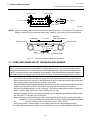
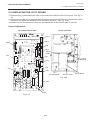
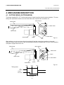
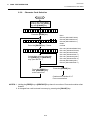
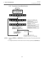
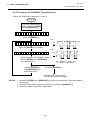
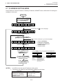
Mechanism
1 Batch mechanism
This is the standard mechanism which let the printer print continuously without winding the label
and tag paper. The strip or auto-cut function is available when the optional module is installed.
2 Auto cut mechanism
When the cutter module is installed, the backing paper and tag paper are cut individually (stop
and cut). Minimum cut length is 25.4 mm (tag paper) or 38 mm (label).
Ribbon
Tag
Ribbon End Sensor
Cutter
Pinch
Roller
Print Head
Platen
Media
Sensor
Feed
Roller
Fig. 1.4
3 Ribbon Saving Mechanism
Two solenoids installed in both sides of the print head automatically lift the print head during
paper feed to minimize ribbon loss.
1-4
1. OUTLINE OF THE SYSTEM
EO10-33008
1. 5 ELCTRONICS SPECIFICATIONS
18) Power supply (Universal power supply : Automatic switching)
QQ model: AC85 ~ 138 V, 45 ~ 66 Hz
QP model: AC187 ~ 276 V, 45 ~ 66 Hz
NOTE: You do not need to chang the voltage, however, make certain that the power supply cord
being used is rated for the voltage supplied.
19) Current consumption
Printing: 260 W max., QQ model: 3.5 A max., QP model : 1.4 A max.
(Stand by : QQ model: 20W/360 mA, QP model : 26W/270 mA)
20) Rush current .................. QQ model : 6.5 A or less, QP model : 11 A or less
1.5 ELECTRONICS SPECIFICATIONS
1) CPU ............................... HD6417708SF60
2) Memory
1 Program:
4MB Flash ROM
2 Backup:
EE-PROM 128 Bytes
3 Image buffer + Work: 16 MB EDO DRAM
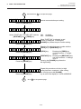
3) Interface
1 RS-232C interface
(1)Communication mode: Full-duplex
(2)Transmission speed:
2400,4800,9600,19200, 38400 BPS (selectable)
(3)Synchronization:
start-stop synchronization
(4)Transmission parameter
■ Parity:
None, EVEN, ODD
■ Start bit:
1-bit
■ Stop bit:
1-bit or 2-bit
■ Word length 7-bit or 8-bit
(5)Error detection
■ Parity check: VRC (Vartical parity check)
■ Framing error: This error occurs when no stop bit is found in the frame specified startig
with the start bit.
■ Overrun error: This error occurs when subsequent data is input before the data input to
the UART from the host is read by the printer.
(6)Data entry code: ASCII, 8-bit code for European characters, 8-bit code for graphic
(7)Receiving buffer: 10KB
(8)Protcol
■ XON/XOFF (DC1/DC3) protocol
• When initialized after power on, this printer becomes ready to receive data and sends
an XON code (11H). (Trasmission or non-transmission of XON code is selectable by
means of the DIP switch.)
• The printer sends an XOFF code (13H) when the blank positions in the receive buffer
becomes 800 Bytes or less.
• The printer sends an XON code (11H) when the blank positions in the receive buffer
are 2KB or more.
• When there are no blank positions in the receive buffer, the printer discards data
received which exceeds the receive buffer capacity, without storing it in the buffer.
(After detecting the XOFF code, the host computer must stop transmission before the
printer receive buffer becomes full.)
•
The ptinter sends an XOFF code (13H) at power off time.
1-5
1. OUTLINE OF THE SYSTEM
EO10-33008
1. 5 ELCTRONICS SPECIFICATIONS
■ READY/BUSY (DTR) protocol
• When initialized after power on, this printer becomes ready to receive data and
converts the DTR signal to "High" level (READY).
• The printer converts the DTR signal to "LOW" level (BUSY) when the blank positions
in the receive buffer amount to 800 Bytes or less.
• The printer converts the DTR signal to "High" level (READY) when the blank position
in the receive buffer amount to 2KB or more.
• When there are no blank position in the receive buffer, the printer discards data
received which exceeds the receive buffer capacity, without storing it in the buffer.
(After detecting a BUSY signal, the host computer must stop transmission before the
printer receive buffer becomes full.)
■ XON/XOFF (DC1/DC3) protocol + READY/BUSY (DTR) protocol
• When initialized after power on, this printer becomes ready to receive data and
converts the DTR signal to "High" level (READY). The printer sends an XON code
(11H).
• When the blank positions in the receive buffer are 800 Bytes or less, the printer
converts the DTR signal to "LOW" level (BUSY) and sends an XOFF code (13H).
• When the bland positions in the receive buffer are 2KB or more, the printer converts
the DTR signal to "High" level (READY) and sends an XON code (11H).
• When there are no blank positions in the receive buffer, the printer discards data
received which exceeds the receive buffer capacity, without storing it in the buffer.
(After detecting the XOFF code or BUSY signal, the host computer must stop
transmission before the printer receive buffer becomes full.)
• The printer sends an XOFF code (13H) at power off time.
■ READY/BUSY (RTS) Protocol
• When initialized after power on, this printer becomes ready to receive data and
converts the RTS signal to "High" level (READY).
• The printer converts the RTS signal to “Low” level (BUSY) when the blank positions in
the receive buffer amount to 800 Bytes or less.
• The printer converts the RTS signal to “High” level (READY) when the blank positions
in the receive buffer amount to 2 KB or more.
• When there are no blank position in the receive buffer, the printer discards data
received which exceed the receive buffer capacity, without storing it in the buffer. (After
detecting a BUSY signal, the host computer must stop transmission before the printer
receive buffer becomes full.)
• Both the DTR signal output from the printer and the DSR signal output from the PC are
always “High”.
NOTES:1. When performing the flow control with Windows, in the port setting screen,
select “Hardware” for flow control. [set to the READY/BUSY (RTS) protocol]
2. Under the READY/BUSY (DTR) protocol, after turning the printer power ON,
send data 200ms after the DTR signal is converted to “High” level (READY).
And under the READY/BUSY (RTS) protocol, after turning the printer power
ON, send data 200ms after the RTS signal is converted to “High” level
(READY).
1-6
1. OUTLINE OF THE SYSTEM
EO10-33008
1. 5 ELCTRONICS SPECIFICATIONS
(9) Pin description
Pin No.
1
2
Signal
FG (Framed Ground)
RD (Received Data)
I/O
Description
-
Ground line for circuit protection.
I
Data line from which the printer receives data from the
host (receive data line).
Logic "1" is "Low" , and "0" "High". It is LOW (MARK)
while no data is being sent.
3
TD (Transmit Data)
O
Data line from which the printer sends data to the host
(send data line).
Logic "1" is "Low", and "0" "High". It is LOW (MARK)
while no data is being sent.
4
CTS (Clear to Send)
I
Input signal from the host.
It must be "High" for the printer to send data.
O
Output signal to the host.
(1) READY/BUSY (DTR) protocol
It indicates there is data to send to the host.
After power is ON, it is always "Hight.
(2) READY/BUSY (DTR) protocol
Indicates whether the printer is ready to receive data.
The signal is at the Low level when the data amount
in the data buffer is near full, and at the high level
when near empty.
5
RTS (Request to Send)
6
DTR (Data Terminal
Ready)
O
Output signal to the host.
(1) READY/BUSY (RTS) protocol
It indicates there is data to send to the host.
After power is ON, it is always "High".
(2) READY/BUSY (DTR) protocol
Indicates whether the printer is ready to receive data
mount in the data buffer is near full, and at the high
level when near empty.
7
SG (Signal Ground)
-
Ground line for all data and control signals.
20
DSR (Data Set Ready)
I
Input siganl from the host.
It must be "High" for the printer to receive data.
1-7
1. OUTLINE OF THE SYSTEM
EO10-33008
1. 5 ELCTRONICS SPECIFICATIONS
(10) Interface circuit
■ Input circuit
RD
CTS
DSR
■ Output circuit
SN75189 or equivalent
SN75188 or equivalent
TD
RTS
DTR
Fig. 1.5
■ Signal level
Input voltage : "H" .. +3V~ + 15V
"L" ... –3V~ – 15V
Output voltage :
Output voltage :
"H" .. +6V ~ +13V
"L" ... –6V ~ –13V
2 Centronics interface
(1) Data input method:
8-bit parallel (DATA 1~8)
(2) Control signals: ACK, BUSY, PAUSE, DATA; STB, INPUT; PRIME, FAULT, PE
(3) Data input code: ASCII, JIS 8-bit code for European characters, 8-bit code for graphic
(4) Receiving buffer: 5KB
(5) Input/Output circuit configuration and Input/Output conditions
Type
Signal Name.
Configuration
SN74LS14 or equivalent
+5V
DATA 1 ~ 8
1K
Logical level (input)
"1" = 2~5V
"0" = 0~0.4V
Input
+5V
INPUT PRIME
DATA STB
SN74LS14 or equivalent
1K
100P
Output
BUSY
FAULT
PAUSE
ACK
PE
SN7406 or equivalent
+5V
1K
Logical level (input)
"1" = 2.4~5V
"0" = 0~0.4V
100P
Fig. 1-6
1-8
1. OUTLINE OF THE SYSTEM
EO10-33008
1. 5 ELCTRONICS SPECIFICATIONS
3 Expansion I/O interface
(1)Interface circuit
■ Input circuit
External controller, etc.
Printer
COM1
Vcc
R
IN0
~
R
IN4
Photo-coupler
TPL521 (TOSHIBA)
Fig. 1-7
There are five input circuits, and each input is a current loop using a photo-coupler.
The anode of the photo-coupler is connected to common pin COM1 in each of the five circuits. Each
cathode is independent. The voltage of Vcc is 24 V (max.) while the diode operating current is 16
mA.
■ Output circuit
External controller, etc.
(In the case of photo-coupler)
Printer
Vcc
OUT0
~
~
OUT5
COM2
Fig. 1-8
There are six output circuits, and each output is an open collector. The voltage of Vcc is 24V (max.)
while the operating current is 150 mA.
For other details, please refer to the Expansion I/O specification.
1-9
1. OUTLINE OF THE SYSTEM
EO10-33008
1. 5 ELCTRONICS SPECIFICATIONS
4) Sensor/Switch
1 Head up switch/Pinch Roller Switch (micro switch)
The head up switch, attached at the left of the print head as viewed from the media outlet, detects
that the print head is ready to print (head is down). When the head lever is lowered, the head
down cam pushes up the print head, the micro switch is turned on and the print head prepares
to print.
The pinch roller switch, interlocking with the head up switch, detects the vertical movements of
the pinch roller. This micro switch is positioned at 90.6 mm to the right of the main frame.
When this switch is turned on (When the pinch roller is down), the pinch roller feeds the media
and the print head prints.
2 Media sensor 1 (Movable type)
This sensor is comprised of the black mark sensor and feed gap sensor. It is positioned 72.1 mm
from the platen. The sensor position is adjustable according to the media width. It moves toward
the main frame a max. of 70 mm by turning the knob counterclockwise.
■ Black Mark Sensor 1 (Reflective sensor)
This sensor detects the difference of potential between the black mark and tag paper to find
the print position of the tag paper. It is located at the home position with the tag paper or print
head before shipment.
Black Mark
Tag Paper
Knob
21.9 mm
70 mm
8 mm
Feed Gap Sensor 1
Black Mark Sensor 1
Main Frame
Fig. 1-9
■ Feed Gap Sensor 1 (Transmissive sensor)
This sensor detects the difference in potencial between the backing paper and the label to find
the print position of the label. The feed gap sensor is located 8 mm to the right of the black
mark sensor.
Feed Gap Sensor 1
Label
29.9 mm
70 mm
Backing paper
8 mm
Knob
Feed Gap Sensor 1
Black Mark Sensor 1
Main Frame
1-10
Fig. 1-10
1. OUTLINE OF THE SYSTEM
EO10-33008
1. 5 ELCTRONICS SPECIFICATIONS
3 Media Sensor 2 (Fixed type)
Like media sensor 1, this sensor is comprised of the black mark sensor and the feed gap sensor.
If the detection point is positioned at the center of the media, there is no need to adjust the sensor
position.
■ Black Mark Sensor 2 (Reflective sensor)
This is a fixed sensor which detects black marks at the center of the tag paper.
■ Feed Gap Sensor 2 (Transmissive sensor)
This is a fixed sensor which detects label gaps at the center of the label.
Center
143.7 mm
Feed Gap Sensor 2
Tag Paper
19.1 mm
Black Mark Sensor 2
Feed Gap Sensor 2
114.6 mm
10 mm
Main Frame
Fig. 1-11
4 Ribbon end sensor (Transmissive sensor)
When printing in thermal transfer mode, this sensor detects the difference in potential between
the ribbon and the ribbon end to indicate the ribbon end. It is positioned 103.2 mm from the platen
and the detection point is 125.2 mm from the main frame.
Ribbon
Ribbon End Sensor (Tr)
Ribbon End Sensor (LED)
Pinch
Roller
Print Head
Platen
103.2 mm
Feed
Roller
1-11
Fig.1-12
1. OUTLINE OF THE SYSTEM
EO10-33008
1. 5 ELCTRONICS SPECIFICATIONS
5 Slit sensor (Transmissive sensor)
This sensor detects the rotation count of the ribbon shaft and the ribbon motors. The ribbon
motors torque works to take up slack in the ribbon and is dependent on the detected count.
The slit sensor is a photo coupler combining an LED and a transistor.
Slit Sensor
(Rewind)
Slit
Slit
Rewind
Slit Gear
Feed Slit Gear
Slit
Slit Sensor (Feed)
Slit
Fig. 1-13
6 Cutter home position switch (micro switch)
A cam positioned at the end of the cutter motor arm turns the micro switch on/off in accordance
with the cycle of the cutter motion (one rotation). The micro switch status indicates if the cutter
is in the home position.
For details, please refer to the Maintenance Manual section 4.1 Cutter Drive.
1-12
EO10-33008
2. SUPPLY SPECIFICATIONS
2. 1 MEDIA
2.SUPPLY SPECIFICATIONS
Infomation regarding the supply specifications contained in Product Description is essential to service
engineers. Detail specifications and other information on the media and ribbon are described in Supply
Manual by model. It is issued by and sent from TOSHIBA TEC H.Q (Sales Division) upon release of new
model or manual's revision. When purchasing the supplies locally, be sure to refer to the Supply Manual
for details, or trouble may occur. Be sure to read carefully and understand the Supply Manual since if
also includes the details about notes, precision of the print start position, limitations on printing, etc.
2.1 MEDIA
Type
Tag Paper
Thermal Label
Auto-cut
On-demand
Auto-cut
Batch
Batch
Item
101.6 ~ 225.0
101.6 ~ 225.0
Width (mm)
10.0 ~ 1368.0 25.4 ~ 1368.0 38.0 ~ 1368.0 10.0 ~ 1368.0 25.4 ~ 1368.0
Length (mm)
0.10 ~ 0.17
0.13 ~ 0.17
Thickness (mm)
200.0 max.
200.0 max.
Outer roll diameter (mm)
I-BEST S / I-BEST W
RICOH: 140LA / OSAKA SEALING: C6TB
Recommended paper
NOTES:
1.
2.
3.
4.
5.
6.
When cutting the thermal label, secure a gap of 6 mm or more and cut in the
middle of the gap.
The thermal paper used for direct thermal printing must not have the specifications which exceed Na+ 800 ppm, K+ 250 ppm and CI-500 ppm.
Some ink used on pre-printed labels may contain ingredients which shorten the
print head's product life. Do not use labels pre-printed with ink which contain hard
sub–stances such as carbonic calcium (Ca CO3) and kaolin (Al2O3, 2SiO2, 2H2O).
The label should be at least three times as long as the detection gap.
Relations between media roll length and core diameter.
L: Media length
d: Media core outside diameter
(D 2-d 2) x
L=
D: Max. roll diameter t: Media thickness
4t
Use of media with a width less than the minimun media width may shorten the
print head life.
1) Thermal Label
<Design>
2.5 mm ~ 20.0 mm
10.0 mm ~ 1368.0 mm
Backing
Paper
76.2 Max.
mm ø200.0 mm
Label
1.5 mm
Fig. 2-1
1.5 mm
98.6 ~ 222.0 mm
101.6 ~ 225.0 mm
BackingPaper
2-1
Label
Fig. 2-2
EO10-33008
2. SUPPLY SPECIFICATIONS
2. 2 RIBBON
2)
Tag Paper
Black Mark
<Design>
76.2 Max.
mm ø200.0 mm
2.5 mm ~ 10.0 mm
25.4 mm ~ 1368.0 mm
Print Side
Fig. 2-4
101.6 mm ~ 225.0 mm
<Non Print Area>
Fig. 2-3
1 mm
2 mm
Cut Position
Printing Area
Printing Area
1 mm
2 mm
1.5 mm
1.5 mm
Black Mark
1.5 mm
1.5 mm
Fig. 2-5
Fig. 2-6
NOTE: Max effective print prea is 213.3 mm (W) x 1364.0 mm (L).
3) Relationship between the head effective print width and paper.
Outside the print range
Outside the print range
Head effective print width
5.85
mm
213.3 mm ± 0.2 mm
5.85
mm
225 mm
(Maximum paper width)
2.2 RIBBON
No.
Item
Specification
1
Shape
Spool type
2
Width
115 ~ 224 mm
3
Max. length
4
Max. OD
5
Back treatment
6
Core
300 m
ø 72 mm
Coated
Material
Cardboard
Shape
See Fig. 2-7.
7
Leader tape
Polyester film (Opaque), 300 – 5 mm long
8
End tape
Polyester film (Opaque),250 – 5 mm long
9
Winding method
The ink side is outside of ribbon winding.
2-2
EO10-33008
2. SUPPLY SPECIFICATIONS
2.3 CARE AND HANDLING OF THE MEDIA RIBBON
4 + 0.2,-1 mm
4 + 0.2,-1 mm
4 + 0.2,-1 mm
25.7 – 0.2 mm
4 + 0.2,-1 mm
228 mm
Fig. 2-7
NOTE: When purchasing ribbon locally, they must meet the above size. There may be TEC-approved
ribbons which do not fall within the above size, however, they have no functional problem.
Leader tape
End tape
(Non Transmissive)
Ink ribbon
Adhesive tape
Adhesive tape
Adhesive tape
Ink outside
Core
Core
Base
Fig. 2-8
Treated back side
Connection between leader tape and ribbon
2.3 CARE AND HANDLING OF THE MEDIA AND RIBBON
CAUTION:
Be sure to read carefully and understand the Supply Manual. Use only media and ribbon which
meet specified requirements. Use of non-specified media and ribbon may shorten the head life and
result in problems with bar code readability or print quality. All media and ribbon should be handled
with care to avoid any damage to the media, ribbon or printer. Read the following guideline carefully.
• Do not store the media and ribbon for longer than the manufactures recommended shelf life.
• Store media rolls on the flat end, do not store them on the curved sides as this might flatten that
side causing erratic media advance and poor print quality.
• Store the media in plastic bags and always reseal after opening. Unprotected media can get dirty
and the extra abrasion from the dust and dirt particles will shorten the print head life.
• Store the media and ribbon in a cool, dry place. Avoid areas where they would be exposed to
direct sunlight, high temperature, high humidity, dust or gas.
• The thermal paper used for direct thermal printing must not have the specifications which exceed
Na+ 800 ppm, K+ 250 ppm and CL-500 ppm.
• Some ink used on pre-printed labels may contain ingredients which shorten the print head's
product life. Do not use labels pre-printed with ink which contain hard substances such
as
carbonic calsium (CaCO3) and kaolin (Al2O3, 2SiO2, 2H2O).
• Avoid using media containing SiO2 or talc which wears the print head protection layer.
For further information please contact your local distributor or your media and ribbon manufacturer.
2-3
EO10-33008
3. OPTIONAL KIT
3.1 CUTTER MODULE: B-4208-QM
3. OPTIONAL KIT
Option Name
Cutter module
Type
B-4208-QM
Use
This cutter module uses a swing cutter. It cuts backing paper
of labels and tag paper automatically in "stop and cut" mode.
To purchase the cutter module, please contact your distributor
or TOSHIBA TEC H.Q. can assist in finding one for you.
This strip module strips the label from the backing paper with
the take-up block and strip block. When the rewinder guide
plate is attached, the tag paper and label with backing paper
are wound. To purchase the strip module, please contact
your distributor or TOSHIBA TEC H.Q. can assist in finding
one for you.
Strip module
B-4908-H-QM
PCMCIA
interface board
This board enables the following PCMCIA cards to be used.
* LAN card: 3 COM EtherLink®III (recommended)
B-8700-PC* ATA card: Conforming to PC card ATA standard
QM
* Flash memory card: 4MB card
3.1 CUTTER MODULE: B-4208-QM
This compact cutter module uses a built-in swing cutter. The specification is provided below:
1 Cutting method .............. Swing cut
2 Cut mode ...................... Stop cut
3 Minimum cut length ....... Tag paper:25.4 mm, Label:38 mm
4 Home position switch .... Micro switch
Cutter
Pinch
Roller
Print Head
32.8 mm
Platen
Feed
Roller
Fig. 3-1
3-1
EO10-33008
3. OPTIONAL KIT
3.2 STRIP MODULE: B-4908-H-QM
3.2 STRIP MODULE: B-4908-H-QM
This strip module strips labels from the backing paper one by one using an exclusive DC motor which
turns the strip roller to feed the backing paper. No backing paper take-up is provided.
1 Print speed: Max.4 ips
2 Available minimum label length: 25.4 mm
3 Available minimum label width: 98.6 mm
3.3 PCMCIA INTERFACE BOARD: B-8700-PC-QM
The PCMCIA Interface board allows use of the following ATA card, LAN card, or flash memory card when
connected to the CPU PC board.
Type
Maker
Description
ATA Card
A card conforming to the PC card ATA standard
LAN Card
3 COM
Ether Link III 3C589D PC
Remarks
Install into the slot (2) only.
(This card installed into the
card
slot (1) will not work.)
Flash Memory
Card (4 MB)
Maxell
EF-4M-TB CC
EF-4M-TB DC
3-2
PRINTED IN JAPAN
EO10-33008
TEC Thermal Printer
B-880 SERIES
Maintenance Manual
Document No. EO18-33007
Original Apr., 2000
(Revised Apr., 2002)
PRINTED IN JAPAN
EO18-33007
TABLE OF CONTENTS
Page
1. UNPACKING ...................................................................................................... 1- 1
1.1 PROCEDURES ........................................................................................... 1- 1
1.2 CHECKS ..................................................................................................... 1- 1
2. MAJOR UNIT REPLACEMENT .......................................................................... 2- 1
2.1 REPLACING THE CPU PC BOARD ........................................................... 2- 2
2.2 REPLACING THE PS UNIT ........................................................................ 2- 3
2.3 REPLACING THE STEPPING MOTORS ................................................... 2- 4
2.4 REPLACING THE RIBBON MOTORS ........................................................ 2- 5
2.5 REPLACING THE SOLENOID .................................................................... 2- 5
2.6 REPLACING THE PRINT HEAD ................................................................ 2- 7
2.7 REPLACING THE PLATEN ........................................................................ 2- 8
2.8 REPLACING THE ROLLER BELT AND FEED ROLLER ........................... 2- 9
2.9 REPLACING THE MEDIA SENSORS ....................................................... 2-11
2.10 REPLACING THE I/O PC BOARD ............................................................. 2-12
2.11 REPLACING THE EXP I/O PC BOARD .................................................... 2-14
2.12 REPLACING THE CENTRO PC BOARD .................................................. 2-14
2.13 PERIODIC PARTS REPLACEMENT ......................................................... 2-15
3. INSTALLATION PROCEDURE FOR OPTIONAL EQUIPMENT ........................ 3- 1
3.1 CUTTER MODULE (B-4208-QM) ............................................................... 3- 1
3.2 STRIP MODULE (B-4908-H-QM) ............................................................... 3- 4
3.3 PCMCIA PC BOARD (B-8700-PC-QM) ...................................................... 3- 5
4. MECHANISM DESCRIPTION ............................................................................ 4- 1
4.1 CUTTER DRIVE .......................................................................................... 4- 1
5. TROUBLESHOOTING ........................................................................................ 5- 1
6. DIAG. TEST OPERATION .................................................................................. 6- 1
7. ON LINE OPERATION ....................................................................................... 7- 1
7.1 RESET OPERATION .................................................................................. 7- 1
7.2 DUMP MODE .............................................................................................. 7- 2
8. PROGRAM DOWN LOAD .................................................................................. 8- 1
8.1 OUTLINE OF FEATURES .......................................................................... 8- 1
8.2 SOFTWARE INSTALLATION ..................................................................... 8- 1
8.3 FIRMWARE DOWNLOAD .......................................................................... 8- 4
CAUTION:
1. This manual may not be copied in whole or in part without prior written permission of
TOSHIBA TEC.
2. The contents of this manual may be changed without notification.
3. Please refer to your local Authorized Service representative with regard to any queries
you may have in this manual.
Copyright © 2000
by TOSHIBA TEC CORPORATION
All Rights Reserved
570 Ohito, Ohito-cho, Tagata-gun, Shizuoka-ken, JAPAN
EO18-33007
1. UNPACKING
1.1 PROCEDURE
1. UNPACKING
1.1 PROCEDURE
1) Open the carton.
2) Unpack the accesories from the carton
3) Unpack the side pads (L)/(R) and the printer from the carton.
4) Place the printer on a level surface.
Owner’s Manual
Left/Right Side Holders
Holder Shaft
Unpacking
Procedure
Holder Base
Media
Holder
Thumbscrew (M-4x6)
Accessory Board
Power Cord
Print Head Cleaner
Side Pad (L)
Side Pad (R)
Thermal printer
Carton
Fig. 1-1
1.2 CHECKS
1) Check for damage or scratches on the machine.
2) Confirm that none of the accessories are missing.
NOTE: Keep the carton and side pads for later transport.
1-1
EO18-33007
2. MAJOR UNIT REPLACEMENT
2. MAJOR UNIT REPLACEMENT
2. MAJOR UNIT REPLACEMENT
WARNING!
Disconnect power cord before replacing important parts.
CAUTION:
1. NEVER separate the ribbon motors from the attaching plate (bracket), because doing so will
change their adjustment. (See Fig. 2-7)
2. NEVER remove the two screws painted red on the side of the print block. (See Fig. 2-10)
3. NEVER remove screws unless directed to do so in this manual. Removing screws may change
pre-set adjustments.
1)
2)
3)
4)
Turn the power off.
Open the right side and top covers.
Remove the six screws (FL-4x6, B-4x6 and B-3x8) to detach the left side cover.
Remove the (B-3x8) screw to remove the bottom plate.
Top Cover
Screw (FL-4x6)
Screw (B-4x6)
Right Side Cover
Screw (B-3x8)
Left Side Cover
Screw (B-3x8)
Bottom Plate
Fig. 2-1
NOTE: Instructions to open the top and right side covers and to remove the left side cover are omitted
from each removal/installation procedure provided below.
■ Lubrication
CAUTION:
1. Lubrication: During parts replacement
2. Kinds of oil: FLOIL G-488: 1 Kg can. (Parts No. 19454906001).
3. Do not spray the inside of the printer with lubricants. Unsuitable oil can damage the
mechanism.
All machines are generally delivered in their best condition. Efforts shoud be made to keep them that
way. Lack of oil, or the presence of debris or dust, may cause an unexpected failure. To maintain
in optimal operating condition, periodically clean the machine and apply the proper kinds of oil to each
part in which librication is needed.
Although the frequency of lubrication varies according to how often the machine is used, as a
minimum it is necessary to lubricate before any part becomes dry. It is also necessary to wipe off
excessive oil or it will collect dirt.
2-1
EO18-33007
2. MAJOR UNIT REPLACEMENT
2.1 REPLACING THE CPU PC BOARD
2.1 REPLACING THE CPU PC BOARD
CAUTION:
Replace only with the same type and rated fuse for continued protection against risk of fire.
1) Disconnect the 3 harnesses from CN2, CN5, and CN7 on the CPU PC Board.
CN2
CN5
CN7
CPU PC Board
Fig. 2-2
2) Remove the 3 screws (SM-3x5 and SM-3x6) to detach the CPU PC board.
SM-3x6 Screw
SM-3x5 Screw
CPU PC Board
Fig. 2-3
3) Replace the CPU PC board and reassemble in the reverse order of removal.
CAUTION:
Be careful when replacing the CPU PC board, since a non-resettable counter (IC15) is installed on
this board. (Refer to section 6.2.1 Maintenance Counter Printing.) If this counter should be reset,
replace IC15.
2-2
EO18-33007
2. MAJOR UNIT REPLACEMENT
2.2 REPLACING THE PS UNIT
2.2 REPLACING THE PS UNIT
CAUTION:
Replace only with the same type and rated of fuse for continued protection against risk of fire.
1) Disconnect the PS cable from CN2 on the I/O PC board.
2) Remove the two screws (FL-4 x 6) to detach the PS unit. Pushing the AC power inlet from behind
will ease the removal of the PS unit.
3) Disconnect the PS cable from the PS unit.
PS Cable
Screw (FL- 4x6)
CN2
I/O PC Board
I/O PC Board
PS Cable
Screw (FL- 4x6)
PS Unit
Fig. 2-4
4) Replace the PS unit and reassemble in the reverse order of removal. Insert the PS cable into the
notch A .
2-3
EO18-33007
2. MAJOR UNIT REPLACEMENT
2.3 REPLACING THE STEPPING MOTOR
2.3 REPLACING THE STEPPING MOTOR
1) Remove the 4 screws (FL-4x6) to detach the front plate.
Feed Roller Belt
Platen Belt
Screw (FL-4x6)
Front Plate
Screw (FL-4x6)
Screw (FL-4x6)
Fig. 2-5
2) Disconnect the cable from CN14 on the I/O PC board.
3) Remove the two screws (SM-4x8), take the two belts off the pinion gear, and remove the stepping
motor.
CN14
Stepping Motor
I/O PC Board
Screw (SM-4x8)
Fig. 2-6
4) When replacing the stepping motor, place the platen belt around the pinion gear first, then the feed
roller belt, so that the partition is positioned between the two belts. Press down on the stepping motor
with 3.5 Kg – 300 g force and secure it so the platen belt and feed roller belt have no slack, are
engaged ,and evenly tense.
5) Reassemble in the reverse order of removal.
2-4
EO18-33007
2. MAJOR UNIT REPLACEMENT
2.4 REPLACING THE RIBBON MORTOR
2.4 REPLACING THE RIBBON MOTORS
CAUTION:
NEVER separate the ribbon motor from the attaching plate because doing so will change their
adjustment.
1) Detach the connector and remove the two SM-3x5B screws to detach the ribbon motors.
Connector
(Red)
FLOIL G-488
FLOIL G-488
Attaching Plate
Ribbon Motor
Dowels
Screw (SM-3x5B)
Riboon Motor
Screw (SM-3x5B)
Attaching Plate
Connector
(Black)
Fig. 2-7
2) Replace the ribbon motors, then align the dowels to attach the ribbon motors. Reassemble in the
reverse order of removal.
2.5 REPLACING THE SOLENOID
NOTE: This procedure can be done without removing the left side cover.
1) Remove the two SM-4x8B screws, detach the connectors, and remove the solenoid unit (R).
2) Remove the two SM-4x8B screws, disconnect the cables from CN1, CN2 and CN3 on the RSV2 PC
board and detach the solenoid unit (L).
Solenoid
CN1 (Solenoid L)
Screw (SM-4x8B)
Solenoid Unit (R)
CN2
(Solenoid R)
CN3
RSV2 PC Board
Solenoid Attaching Plate
Solenoid Unit (L)
Connecter
Fig. 2-8
2-5
EO18-33007
2. MAJOR UNIT REPLACEMENT
2.5 REPLACING THE SOLENOID
3) Remove the two SM-3 x 6B screws each from the solenoid units (L) and (R) to detach the solenoid.
4) Replace the solenoid and attach it to the solenoid attaching plate. Be careful of the differences in
length of the solenoid cables when installing the solenoid.
5) Assemble the solenoid unit so that the head up link engages the spring pin.
Spring Pin
Solenoid
Head Up Link
Fig. 2-9
NOTE: Make sure to remove any dust that appears during removal or installation because it may affect
the print quality.
CAUTION:
Take care to orient the screws so that they are vertically aligned with the solenoid attaching plate.
6) Insert piled 10 pieces of tag paper of 8 inches (203.2 mm) in width, 0.16 mm in thickness (I-BESTS is recommended) between the print head and the platen. Then turn the head lever to the LOCK
position.
7) Press and hold the link against the solenoid, and then press and fit the solenoid unit sungly to the
link. Secure the solenoid unit with the screws.
8) Reassemble in the reverse order of removal.
Link
Press
Solenoid Unit
Press
Print Head
Platen
Paper Thickness: 1.6 mm
Fig. 2-10
2-6
EO18-33007
2. MAJOR UNIT REPLACEMENT
2.6 REPLACING THE PRINT HEAD
2.6 REPLACING THE PRINT HEAD
CAUTION:
1. NEVER touch the element when handling the print head.
2. NEVER touch the connector pins to avoid damage to the print head by static electricity.
3. NEVER remove the two screwws painted red on the side of the print block.
NOTE: This procedure can be done without removing the left side cover.
1) Remove the two (B-4x4) screws to detach the head cover plate.
2) Pull right to remove the front shaft.
Screw (B-4 x 4)
Head Cover Plate
Front Shaft
Fig. 2-11
3) Turn the head lever counterclockwise to lift the print head.
4) Remove the head fixing screw and pull out the print head.
5) Disconnect the two cables and remove the print head.
Connector
Print Head
Head Lever
Head Fixing Screw
Connecter
NOTE: Never remove the bracket.
6) Replace the print head and reassemble in the reverse order of removal.
7) Refer to page 6-69 and clear the maintenance counter.
8) Refer to page 6-54 and perform a test print.
2-7
Fig. 2-12
EO18-33007
2. MAJOR UNIT REPLACEMENT
2.7 REPLACING THE PLATEN
2.7 REPLACING THE PLATEN
1) Remove the front plate. (Refer to Fig. 2-5.)
2) Loosen the two screws (SM-4 x 10C) securing the stepping motor.
3) Remove the (FL-4 x 6) screw to detach the platen positioning plate.
4) Take the platen belt off the platen pulley, move the platen fully to the right and remove the platen from
the left end.
Platen Belt
Screw (FL-4 x 6)
Platen Pulley
Platen
Platen Positioning Plate
Fig. 2-13
5) Replace and install the platen, then place the platen belt around the platen pulley.
6) Install the platen positioning plate.
7) Press down on the stepping motor with 3.5 Kg – 300 g force and secure it so the platen belt and the
feed roller belt have no slack, are engaged and evenly tense.
8) Reassemble the remaining parts in the reverse order of removal.
2-8
EO18-33007
2. MAJOR UNIT REPLACEMENT
2.8 REPLACING THE ROLLER BELT AND FEED ROLLER
2.8 REPLACING THE ROLLER BELT AND FEED ROLLER
1) Lower the pinch roller lever.
2) Remove the white screw to detach the ribbon end sensor plate.
3) Remove the FL-3 x 5 screw, cut the cable band and remove the head-up switch.
4) Detach the connector of the ribbon end sensor.
5) Removal the pinch roller block.
Cable Band
FL-3 x 5
Connector
White Screw
Pinch Roller Block
Notch
Ribbon End
Sensor Plate
Head-Up Switch
Pinch Roller Lever
Stud
Fig. 2-14
NOTE: Fit both sides of the studs into the notches when installing the ribbon end sensor plate.
6) Remove the four E-rings (E-5), pinch roller holder, bush, pinch roller washer, and then roller belt.
E-ring (E-5)
E-ring (E-5)
Bush
Pinch Roller Holder
Pinch Roller Washer
Roller Belt
Fig. 2-15
2-9
EO18-33007
2. MAJOR UNIT REPLACEMENT
2.8 REPLACING THE ROLLER BELT AND FEED ROLLER
7) Remove the two (FL-4x6) screws and detach the media plate.
8) Remove the two (FL-4x6) screws and detach the media guide unit.
9) Loosen the two (SM-4x10C) screws securing the stepping motor.
10) Remove the two screws to detach the feed roller positioning plate.
11) Take the feed roller belt off the feed roller, move the feed roller fully to the left and remove the feed
roller form the right end.
Roller Pulley
Feed Roller Belt
Feed Roller Feed
Stud
Notch
Feed Roller
Positioning Plate
Media Guide Unit
Screw (FL-4x6)
Screw (FL-4x6)
Media Plate
Fig. 2-16
NOTE: Fit both sides of the studs into the notches when installing the media guide unit.
12) Replace and install the feed roller, place the feed roller belt around the feed roller pulley.
13) Install the feed roller positioning plate.
14) Press down on the stepping motor with 3.5 Kg – 300 g force and secure it so the platen belt and
the feed roller belt have no slack, are engaged and evenly tense.
15) Reassemble the remaining parts in the reverse order of removal.
2-10
EO18-33007
2. MAJOR UNIT REPLACEMENT
2.9 REPLACING THE MEDIA SENSOR
2.9 REPLACING THE MEDIA SENSOR
CAUTION:
1. When using the fixed sensor, line up the feed gap sensors between the upper and lower sensors.
2. When shipped from the factory, the black mark sensor is positioned at the center of the effective
print area and the feed gap sensor is located 10 mm left of center as viewed from the front.
1) Detach the 4 connectors from the fixed/movable media sensors.
2) Remove the two screws (FL-3 x 4) and the sensor holder to detach the media sensor unit.
3) Turn the knob of the sensor shaft clockwise and remove the movable media sensor.
4) Remove the E-ring (E-3) from the sensor shaft and detach the lower fixed media sensor.
Media Sensor Unit
Knob
Fixed Media Sensor
E-ring (E-3)
Movable Media Sensor
Media Guide Plate
Screw (FL-3x4)
Connecter
Connecter
Fig. 2-17
5) Remove the white screw to detach the media guide plate.
6) Remove the two SM-3 x 6B screws, then unclamp and detach the upper fixed media sensor.
Upper Fixed Media Sensor
Screw (SM-3 x 6B)
Media Guide Plate
White Screw
B
Clamp
Fig. 2-18
7) Replace the fixed/movable media sensors and reassemble in the reverse order of removal.
2-11
EO18-33007
2. MAJOR UNIT REPLACEMENT
2.10 REPLACING THE I/O PC BOARD
2.10 REPLACING THE I/O PC BOARD
1) Disconnect the 13 harnesses from CN1 to CN3 and CN5 to CN14 on the I/O PC board. (See Fig. 219)
2) Remove the two SM-3x5 screws and one SM-4x8 screws from the I/O PC board. Remove the I/O PC
board from the printer by releasing it from the locking supports. (See Fig. 2-20)
3) Replace the I/O PC board with a new one and reassemble in the reverse order of removal.
Sensor Adjustment
I/O PC Board (Parts Side)
Printer (Left Side)
CN14
CN13
CN12
CN8
CN10
SM-3x5
Screw
CN7
CN9
Locking
support
CN11
CN6
CN3
CN5
SM-4x8 Screw
SM-3x5 Screw
Fig. 2-20
CN2
CN1
Fig. 2-19
2-12
I/O PC Board
EO18-33007
2. MAJOR UNIT REPLACEMENT
2.10 REPLACING THE I/O PC BOARD
Sensor Adjustment
After replacing the I/O PC board or changing ribbon type, be sure to adjust the sensors in the following
procedure.
Ribbon End Sensor
1) Set the ribbon so that the ribbon end sensor can detect the ribbon. Then turn on the power.
NOTE: Use TOSHIBA TEC-approved ribbon (TTP-110).
2) Measure the voltage between TPRETR pin on the I/O PC board and the printer inner plate (GND)
with a oscilloscope, and adjust the voltage to 3.0–0.2V by turning VR1 on the I/O PC board.
3) Set the ribbon end portion (not ink portion) so that the ribbon end sensor can detect it. Measure the
voltage again. If it is over 0.4V, re-adjust the voltage from step (2) again.
4) After the adjustment is successfully made, turn off the printer and reassemble the left side cover.
I/O PC Board (Parts Side)
VR1
TPRETR Pin
Fig. 2-21
Black Mark Sensor
Refer to the adjustment procedure for the black mark sensor (Section 6.5.2) which is adjusted by key
entries in system mode.
Feed Gap Sensor
Refer to the adjustment procedure for the feed gap sensor (Section 6.5.3) which is adjusted by key
entries in system mode.
2-13
EO18-33007
2. MAJOR UNIT REPLACEMENT
2.11 REPLACING THE EXP I/O PC BOARD
2.11 REPLACING THE EXP I/O PC BOARD
(1) Remove the two SM-3x6 screws to detach the EXP I/O PC board from the rear cover.
(2) Disconnect the harness from CN1 on the EXP I/O PC board.
EXP I/O PC Board
CN1
SM-3x6 Screw
Harness
Fig. 2-22
(3) Replace the EXP I/O PC board with a new one, then reassemble in the reverse order of removal.
2.12 REPLACING THE CENTRO PC BOARD
(1) Refer to Section 2.11 to detach the EXP I/O PC board.
(2) Remove the two SM-3x6C screws to detach the CENTRO PC board from the rear cover.
(3) Disconnect the harness from CN1 on the CENTRO PC board.
CENTRO PC Board
SM-3x6C Screw
CN1
Harness
Fig. 2-23
(4) Replace the CENTRO PC board with a new one, then reassemble in the reverse order of removal.
2-14
EO18-33007
2. MAJOR UNIT REPLACEMENT
2.13 PERIODICAL PART REPLACEMENT
2.13 PERIODIC PARTS REPLACEMENT
No.
Part Name
Part No.
Standard Interval of Replacement
1
Ribbon Motor
FMBB0030501
730 Km
FMBB0030502
2
Solenoid
FMBB0032104
1,000,000 times
FMBB0032105
3
Platen
FMBC0044501
50 Km
4
Feed Roller
FMBC0044601
50 KMm
Since the above intervals are the standard values for a fully maintained machine, they are not
guaranteed, The values vary depending on the operating environment (dust or debris) or use of proper
media and ribbon.
2-15
EO18-33007
3. INSTALLATION PROCEDURE FOR OPTIONAL EQUIPMENT
3.1 CUTTER MODULE (B-4208-QM)
3. INSTALLATION PROCEDURE FOR OPTIONAL
EQUIPMENT
WARNING!
Make sure to unplug the power cord before installing any optional equipment.
3.1 CUTTER MODULE (B-4208-QM)
NOTE: This module cannot be used together with the B-4908-H-QM strip module. Remove the strip
module if it has been attached to the printer.
Description
Q’ty/Unit
Description
Q’ty/Unit
Cutter Unit
1
Cutter Attaching Screw
2
Cutter
1
Screw (FL-4x6)
2
Cutter Harnes
1
Screw (SM-4x6C)
1
Cutter Support
1
Cleaner
1
1) Open the right side cover and the top cover. (See Fig. 2-1.)
2) Remove the left side cover. (See Fig. 2-1.)
3) Remove the front plate. (See Fig. 2-5.)
4) Remove the screw (SM-4x8B) and two connectors to detach the operation panel.
5) Attach the cutter support to the main frame with the two screws (FL-4x6).
Screw (SM-4x8B)
Screw (FL-4x6)
Connector
Operation Panel
Main Frame
Connector
Cutter Support
Screw (FL-4x6)
Fig. 3-1
6) Install the cutter unit with the attached four screws (cutter attaching screw, SM-4x6C and
FL-4x6).
3-1
EO18-33007
3. INSTALLATION PROCEDURE FOR OPTIONAL EQUIPMENT
3.1 CUTTER MODULE (B-4208-QM)
7) Connect the cutter harness to CN1 on the cutter I/F PC board through the opening of the cutter unit.
When installing the cutter, make sure that the cutter guide is not in contact with the platen. If it is, print
failure or noise may be caused.
Platen
Cutter Unit
Screw (SM-4x6C)
Cutter Unit
Connector (CN1)
Opening
Cutter Attaching Screw
Screw (FL-4x6)
Cutter I/F PC Board
Cutter Harness
Fig. 3-2
8) Connect the cutter harness to CN4 on the I/O PC board.
I/O PC Board
Cutter Unit
CN4
Cutter Harness
Fig. 3-3
9) Mount the cutter cover with the two screws.
Screw
Cutter Cover
Cutter Attaching Screw
3-2
Fig. 3-4
EO18-33007
3. INSTALLATION PROCEDURE FOR OPTIONAL EQUIPMENT
3.1 CUTTER MODULE (B-4208-QM)
10) Mount the operation panel and the left side cover on the printer.
11) Close the top and right covers.
12) After reassembly is complete, perform a test print to confirm that the cutter works properly. If the print
start position becomes misalign when media is fed in the reverse direction, fine adjust the back feed
value using the Back Feed Fine Adjustment procedure in diag. mode.
NOTE:
Retain the parts that are removed during installation of the cutter unit. They will be required
when the printer is modified to a standard type.
Removed Parts
Q'ty/Unit
Removed Parts
Q'ty/Unit
Front plate
1
Screw (FL-4x6)
3
■
Screw
(SM-4 x 6)
Cutter Guide Plate B
0.5 mm
Fixed Cutter
0.1 ~ 0.4 mm
Adjusting the Cutter Guide Plates
After replacing the cutter unit the following adjustment procedure should be employed to prevent
paper jams.
1. Attach the cutter guide plate A with two SM-4 x 6C screw so that the fixed cutter is positioned 0.1
mm to 0.4 mm above the bottom of the cutter guide plate A.
2. Attach the cutter guide plate B with two FL-4 x 8 screws so that there is a clearance of 0.5 mm
between the cutter guide plate A and cutter guide plate B using a clearance gauge.
Screw
(FL-4 x 8)
Cutter Guide Plate A
3-3
Fig. 3-5
EO18-33007
3. INSTALLATION PROCEDURE FOR OPTIONAL EQUIPMENT
3.2 STRIP MODULE (B-4908-H-QM)
3.2 STRIP MODULE (B-4908-H-QM)
NOTE: This module cannot be used together with the B-4208-QM cutter module. Remove the cutter
module if it has been attached to the printer.
Description
Q'ty/Unit
Strip Unit
1
Strip Harness
1
1) Open the right side cover and the top cover. (See Fig. 2-1)
2) Remove the left side cover (See Fig. 2-1)
3) Remove the front plate (See Fig. 2-5)
4) Remove the operation panel (See Fig. 3-5)
5) Connect the strip harness to the CN2 on the PWM PC board through the opening of the strip base.
6) Install the strip unit to the printer with the four FL-4 x 6 screws removed in STEP 3.
7) Connect the strip harness to the CN4 on the I/O PC board.
8) Connect the strip sensor harness to the CN15 on the I/O PC board.
Screw (FL-4x6)
I/O PC Board
Screw (FL-4x6)
PWM PC Board
Strip Harness
CN15
CN4
CN2
Strip Base
Opening
Strip Unit
Strip Harness
Screw (FL-4x6)
Strip Sensor Harness
Fig. 3-6
9) Mount the operation panel and the left side cover on the printer.
10) Close the top and right covers.
11) Refer to Section 6.4 of the Maintenance Manual to load the label and make a test print to check
forproper strip issue. If not, refer to Section 6.3.2 of the Maintenance Manual to adjust the strip
position.
3-4
EO18-33007
3. INSTALLATION PROCEDURE FOR OPTIONAL EQUIPMENT
3.3 PCMCIA PC BOARD (B-8700-PC-QM)
3.3 PCMCIA PC BOARD (B-8700-PC-QM)
Description
Installation Manual
PCMCIA PC Board
SM-3x8 Screw
Ferrite Core
PCB Holder Plate
Q’ty/Unit
1
1
4
1
1
1) Turn the power off.
2) Open the right side and top covers (See Fig. 2-1).
3) Remove the six screws (FL-4x6, B-4x6 and B-3x8) to detach the left side cover. (See Fig. 2-1).
4) Remove the two FL-3x5 screws to detach the blind plate.
Blind Plate
FL-3x5 Screw
Rear Cover
Fig. 3-7
5) Detach the three harnesses from CN2, CN5 and CN7 on the CPU PC board.
CN2
CN5
CN7
Harness
CPU PC Board
Fig. 3-8
3-5
EO18-33007
3. INSTALLATION PROCEDURE FOR OPTIONAL EQUIPMENT
3.3 PCMCIA PC BOARD (B-8700-PC-QM)
6) Fix the PCB holder plate to the CPU PC board with the SM-3x8 screw so that the PCB holder plate
aligns with the PCB support plate.
PCB Holder Plate
PCB Support
Plate
CPU PC Board
SM-3x8 Screw
Fig. 3-9
7) Connect the CN51 on the PCMCIA PC board to the CN9 on the CPU PC board.
8) Fix the PCMCIA PC board with the three SM-3x8 screws on the CPU PC board and the PCB holder
plate.
PCB Holder Plate
CPU PC Board
SM-3x8 Screw
PCMCIA PC Board
Fig. 3-10
SM-3x8 Screw
9) Return the three harnesses to CN2, CN5, CN7 on the CPU PC board.
10) Attach the ferrite core to any cable attached to a PCMCIA PC board (Example LAN card) that may
be inserted into the card slot. Place the ferrite core as close to the PCMCIA card as possible.
11) Reassemble the left side cover in the reverse order removal.
3-6
EM18-33013
4. MECHANISM DESCRIPTION
4.1CUTTER DRIVE (CUTTER MODE)
4. MECHANISM DESCRIPTION
4.1 CUTTER DRIVE (CUTTER MODE)
The printer supplies DC + 27 V to the cutter motor to rotate it and the clutch counter clockwise. The arm
swings like a pendulum and moves the fixed slide cutter up and down to make a cut.
Micro Switch
Fixed Cutter
Slide Cutter
Slide Cutter
Cutter Motor
Clutch
Cutter Motor
Fig. 4-1
Arm
After making a cut, the arm turns the micro switch off and the cutter home position is detected.
When the cutter does not return to the home position because of a paper jam, an error occurs and the
next piece of paper will not be cut.
Micro Switch
Fixed Cutter
Slide Cutter
Clutch
Slide Cutter
Cutter Motor
Clutch
Arm
Cutter Motor
Fig. 4-2
Open
Close
Timing chart
+27
MOTOR
CHOME
Micro Switch
Cutting
(one cycle)
4-1
Open
EO18-33007
5. TROUBLESHOOTING
5. TROUBLE SHOOTING
5. TROUBLESHOOTING
Problems
Cause
Solution
Power does not turn
ON.
1. Input voltage to the printer is not
within the rated voltage.
(Check by CN1 on the PS unit.)
2. Output voltage from the printer is not
within the rated voltage.
(Check that the voltage between Pin
4 and Pin 6 (GND) of CN1 on the PS
unit is 27 V.
And check that the voltage between
Pin 11 and Pin 6 ( GND) is 5 V.)
3. No voltage to the I/O PC board.
(Check that the voltage between Pin
1 and Pin 5 (GND) of CN2 on the I/O
PC board is 27 V.
And check that the voltage between
Pin 11 and Pin 10 (GND) is 5 V.)
4. Failure of CPU PC board.
• Replace the power cable orpower
inlet.
LED or LCD does not
light.
1. Failure of the LED board/LCD
2. Failure of the LCD/LED harness
3. Failure of the CPU PC board
• Replace the LED board/LCD.
• Replace the LCD/LED harness.
• Replace the CPU PC board.
Poor printing
1. The print paper is of poor quality.
• Use the media approved by
TOSHIBA TEC.
• Clean the print head.
• Fasten the head lever completely.
2. Dirty print head
3. The head lever fastens the print head
incompletely.
Printer does not print
Dot missing
• Replace the PS unit.
• Replace the power harness.
• Replace the CPU PC board.
1. Print head failure
2. Connection of the print head
connector is incomplete,a bad
contact, or broken wires.
3. Failure in rewinding/feeding of the
ribbon.
4. Failure of the CPU PC board
5. Failure of the software
6. Failure of the printer cable
• Replace the print head.
• Connect the harness completely,
or replace the harness.
1. Broken print head element
2. Broken print head cable wires
3. Failure of the CPU PC board
4. Failure of the I/O PC board.
•
•
•
•
5-1
• Replace the ribbon rewind motor,
ribbon feed motor or I/O PC board.
• Replace the CPU PC board.
• Check the program.
• Replace the printer cable.
Replace the print head.
Replace the print head harness.
Replace the CPU PC board.
Replace the I/O PC board.
EO18-33007
5. TROUBLESHOOTING
5. TROUBLE SHOOTING
Problems
Blurred print
Cause
Solution
1. Poor media quality.
• Use only TOSHIBA TEC specified
media.
• Clean the print head and remove
any dust from the media.
2. Dust is on the media.
Ribbon wrinkle
1. Poor ribbon quality
2. Ribbon is not rewound or fed
smoothly.
Ribbon end error
1. Poor ribbon quality
2. Improper voltage applied to the ribbon
end sensor
3. Failure of the ribbon end sensor
4. Failure of the circuit which controls
the ribbon end sensor.
Label feed failure
1. Paper is not set properly.
2. Paper of poor quality
3. Improper adjustment of the feed gap
sensor or black mark sensor.
4. The proper media sensor is not
selected.
5. Threshold is improper.
6. Failure of the feed gap sensor or
black mark sensor
7. Labels cannot be stripped off the
backing paper or the backing paper
with labels cannot be wound properly.
8. The cutter mechanism is not installed
properly.
9. Failure of the stepping motor
Communication error
1. Failure of the communication cable
2. Failure of the RS-232C connecter
3. Failure of the communication
connector
4. Failure of the PC or application
software
5. Failure of the CPU PC board
5-2
• Use only TOSHIBA TEC specified
ribbon.
• Replace the ribbon rewind mo tor
or ribbon feed motor.
• Use only TOSHIBA TEC specified
ribbon.
• Refer to page 2-13 to adjust the
ribbon end sensor.
• Replace the ribbon end sensor.
• Replace the I/O PC board.
• Set the paper properly.
• Use paper approved by TOSHIBA
TEC.
• Re-adjust the sensor.
• Select the media sensor by DIP
switch and adjust the sensitivity of
the sensor.
(Refer to page 6-40, 41)
• Set the threshold.
(Refer to Owner’s Manual.)
• Replace the feed gap sensor or
black mark sensor.
• Replace the take-up motor or I/O
PC board.
• Install the cutter mechanism
properly.
• Replace the stepping motor or I/O
PC board.
• Replace the cable.
• Replace the connector.
• Replace the connector.
• Modify the program.
• Replace IC2 (MC145407).
If the trouble is not solved, replace
the CPU PC board.
EO18-33007
TABLE OF CONTENTS
Page
6. DIAG. TEST OPERATION ........................................................................6- 1
6.1 OUTLINE OF THE DIAG. TEST OPERATION ................................ 6- 1
6.2 SELF TEST MODE ..........................................................................6- 3
6.2.1 Maintenance Counter Printing ............................................6- 3
6.2.2 Automatic Diagnostic Printing .............................................6- 8
6.2.3 Head Broken Element Check .............................................6-14
6.3 PARAMETER SETTING MODE .....................................................6-15
6.3.1 Feed Length Fine Adjustment ............................................6-17
6.3.2 Cut/Strip Position Fine Adjustment .................................... 6-18
6.3.3 Back Feed Length Fine Adjustment ...................................6-19
6.3.4 X Axis Fine Adjustment ......................................................6-24
6.3.5 Print Tone Fine Adjustment ...............................................6-26
6.3.6 Character Code Selection ..................................................6-27
6.3.7 Font Zero Selection ............................................................6-28
6.3.8 Baud Rate Selection ..........................................................6-29
6.3.9 Data Length Selection ........................................................6-30
6.3.10 Stop Bit Selection ...............................................................6-31
6.3.11 Parity Selection ..................................................................6-32
6.3.12 Transmission Control Mode Selection ............................... 6-33
6.3.13 Language Selection for LCD Message ..............................6-34
6.3.14 Auto Forward Wait in Cut Mode ......................................... 6-35
6.3.15 Head up ON/OFF Setting in Cut Mode ..............................6-36
6.3.16 Ribbon Saving Module Selection .......................................6-37
6.3.17 Control Code Selection ......................................................6-38
6.3.18 Ribbon Type Selection .......................................................6-40
6.3.19 Ribbon Motor Drive Voltage Fine Adjustment ....................6-41
6.3.20 Strip Wait Status Selection ................................................6-42
6.3.21 FEED Key Function Selection ............................................6-43
6.3.22 Threshold Manual Fine Adjustment for the
Black Mark Sensor .............................................................6-44
6.3.23 Threshold Manual Fine Adjustment for the
Feed Gap Sensor ...............................................................6-45
6.3.24 Kanji Code Selection ..........................................................6-48
6.3.25 Euro Font Code Selection ..................................................6-49
6.3.26 Auto Print Head Broken Element Check ............................ 6-50
6.3.27 Centronics I/F ACK/BUSY Timing Selection ...................... 6-51
6.3.28 Web Printer Function Selection ......................................... 6-52
6.3.29 Media Sensor Selection .....................................................6-53
EO18-33007
(Revision Date: Apr. 25, 2002)
Page
6.4
6.5
6.6
6.7
6.8
TEST PRINT MODE ....................................................................... 6-54
6.4.1 Normal Test Print ............................................................... 6-54
6.4.2 Process Test print .............................................................. 6-60
SENSOR SETTING MODE ............................................................6-62
6.5.1 Thermistor Check (Read only) ........................................... 6-62
6.5.2 Black Mark Sensor Adjustment .......................................... 6-63
6.5.3 Feed Gap Sensor Adjustment ............................................ 6-64
6.5.4 Paper End Setting for Black Mark Sensor ......................... 6-65
6.5.5 Paper End Setting for Feed Gap Sensor ........................... 6-66
RAM CLEAR MODE ....................................................................... 6-67
6.6.1 Maintenance Counter Clear ............................................... 6-70
6.6.2 Parameter Clear .................................................................6-71
IP ADDRESS SETTING MODE ...................................................... 6-72
BASIC SETTING MODE .................................................................6-74
EO18-33007
(Revision Date: Apr. 25, 2002)
6.1 OUTLINE OF THE DIAG. TEST OPERATION
6. DIAG. TEST OPERATION
6. DIAG. TEST OPERATION
6.1 OUTLINE OF THE DIAG. TEST OPERATION
In system mode the diag. test operation is used to diagnose the printer and to set the parameters by using
the [FEED], [RESTART] and [PAUSE] keys on the operation panel. Diag. test operation (Type I) is
started from the power off state and the parameter setting (Type II) is started while the printer is on-line
or printing. For further details, please refer to the corresponding pages.
NOTE: Every size in this manual is written in millimeter. To obtain the size in inch, divide by 25.4.
■ Type I
Power off
Turn on the power while
holding down the [FEED]
key and [PAUSE] key.
< 1 > D I A G N O S T I C
Press the [RESTART] key.
Press the [FEED] key.
< 2 > P A R A M E T E R
Press the [RESTART] key.
< 3 > T E S T
< 4 > S E N S O R
Press the [FEED] key.
Press the [FEED] key.
A D J U S TM E N T
Press the [RESTART] key.
Press the [FEED] key.
C L E A R
Press the [RESTART] key.
< 6 > I P
S E T
P R I N T
Press the [RESTART] key.
< 5 > R A M
V1 . 0 A
Press the [FEED] key.
A D D R E S S
Press the [RESTART] key.
Press the [FEED] key.
< 7 > B A S I C
Press the [RESTART] key.
Press the [FEED] key.
■ Self Test Mode (See page 6-3)
Data from the maintenance counter and
automatic diagnosis are printed on the media.
■ Parameter Setting Mode (See page 6-15)
Fine adjustment of the feed length, cut/strip
position, back feed length, X axis, print tone,
thresholds of the black mark sensor and feed
gap sensor, ribbon motor drive voltage, and
selection of character code, font zero, baud rate,
data length, stop bit, parity, transmission control
mode, language of LCD message, auto forward
wait and head up ON/OFF in cut mode, ribbon
saving module, control code, ribbon type, strip
wait status, feed key function, kanji code, EURO
font cod, Centronics I/F ACK/BUSY timing, Web
printer, and auto print head broken element
check are available in this mode.
■ Test Print Mode (See page 6-54)
Print condition and test print type (slant line,
characters and bar code) are selectable.
■ Sensor Setting Mode (See page 6-62)
A thermistor check and the adjustment of the
black mark and feed gap sensors are available
in this mode.
A transmission check is made to both a print
head thermistor and an environmental
temperature thermistor.
■ RAM Clear Mode (See page 6-67)
Data from the maintenance counter is cleared
and parameter setting is initialized in the RAM
clear mode.
■ IP Address Setting Mode (See page 6-72)
Host IP address, Printer IP address, and Gateway
IP address settings are available in this mode.
■ BASIC Setting Mode (See page 6-74)
Setting the BASIC specification and trace
specification to be enabled/disabled, and
displaying the program file/data file are available
in this mode.
6-1
EO18-33007
6. DIAG. TEST OPERATION
6.1 OUTLINE OF THE DIAG. TEST OPERATION
In system mode the [FEED], [RESTART] and [PAUSE] keys function as described below.
Key Name
[FEED] key
[RESTART] key
[PAUSE] key
Function
Used to start the system mode as a [PAUSE] key does. Used to select the
parameter mode or to fine adjust the parameters in the negative direction ( - ).
Used to select the parameter mode or to fine adjust the parameters in the
positive direction (+)
Used to start the system mode as a [FEED] key does and to select the parameter
mode. Used as an enter key.
■ Type II
The parameter setting such as feed length fine adjustment or cut/strip position fine adjustment can be
changed while the printer is on-line or printing. Pressing the [PAUSE] key causes the printer to enter
parameter setting mode. Reset mode is provided for this procedure to cancel the steps which follow the
[PAUSE] key without turning the power off.
Power on
O N
L I NE
Press the [PAUSE] key. (See NOTE 1.)
P AU S E
5
Press the [PAUSE] key.
Hold down the [RESTART] key for
more than 3 seconds. (See NOTE 2.)
Indicates the number of
remaining media when the
[PAUSE] key is pressed.
< 1> R E SE T
(See NOTE 3.)
Press the [FEED] key.
< 2> P A RA ME TE R S E T
Press the [FEED] key
and [RESTART] key
Press the [PAUSE] key.
at the same time.
Refer to Section 6.3 Parameter Setting Mode
for the following procedure.
Press the [RESTART] key.
NOTES: 1. Pressing the [PAUSE] key during printing causes the printer to pause printing and
show the number of remaining media.
2. If the [RESTART] key is released within 3 seconds, the printer will resume printing
because the [RESTART] key is activated.
3. Since the reset is performed when terminating this mode, the printer cancels the
remaining media and returns to on-line mode. This reset will not clear the changed
parameter settings.
6-2
EO18-33007
6. DIAG. TEST OPERATION
6.2 SELF TEST MODE
6.2 SELF TEST MODE
In self test mode the printer status is printed in two types of sample print.
6.2.1 Maintenance Counter Printing
The data from 1 to 53 on a sample print is printed. This data is the printer status and the
value set in the parameter setting mode.
Power off
Turn on the power while
holding down the [FEED]
key and [PAUSE] key.
< 1> D I AG N OST IC
V 1. 0 A
Continued on Section 6.2.2
Automatic Diagnostics Printing.
Press the [PAUSE] key.
R IB B O N
Press the [PAUSE] key.
TR A N SM IS SIV E
Select the ribbon type from those
at the right by pressing the
[FEED] key or [RESTART] key.
Press the [PAUSE] key.
M AI N T EN AN CE
NO RIBBON (No ribbon : Thermal direct)
TRANSMISSIVE
(Transmissive ribbon : Thermal transfer)
NO TRANS.
(Non-transmissive ribbon : Thermal transfer)
CO U N TE R
Press the [PAUSE] key.
C HE C K IN G
&
P RI N T I N G
The printer is checking or printing
the status
The result of the self test
is printed. After printing,
the initial display will be
shown.
NOTES: 1. If the maintenance counter printing results in an error, the printer will display the error
message and stop printing. The error status can be cleared by the [PAUSE] key,
however, the display will return to the initial display “<1> DIAG. V1.0A”. Printing is not
automatically resumed after the error is cleared.
2. Both label and tag paper can be used for printing.
6-3
EO18-33007
(Revision Date: Apr. 25, 2002)
6.2 SELF TEST MODE
6. DIAG. TEST OPERATION
■ Sample Print
[Print Condition]
• Preset count
• Print speed
• Sensor
• Printing method
• Supply length
• Issuing mode
:
:
:
:
:
:
1
4"/sec.
No sensor
Thermal transfer
140 mm
Batch printing
(without rewinder)
(1)
(2)
(3)
(4)
(5)
(6)
(7)
TL FEED
FEED
PRINT
CUT
HEAD U/D
RIBBON
SOLENOID
1.1 km
1.1 km
0.5 km
96
32
3h
0h
(8)
(9)
(10)
232C ERR
SYS ERR
PW FAIL
255
0
0
(11)
(12)
THRESHOLD (R)
THRESHOLD (T)
1.0 V
0.7 V
(13)
(14)
(15)
(16)
(17)
(18)
(19)
(20)
(21)
(22)
(23)
(24)
(25)
(26)
(27)
(28)
(29)
(30)
(31)
(32)
(33)
(34)
(35)
(36)
(37)
(38)
(39)
(40)
(41)
(42)
FONT [PC-850]
CODE [AUTO]
RIBBON
STATUS
SPEED
DATA LENG.
STOP BIT
PARITY
CONTROL
MESSAGE
FORWARD WAIT
HEAD UP CUT
RIBBON SAVE
SENS POSI
FEED KEY
KANJI
EURO CODE
AUTO HD CHK
WEB PRINTER
HOST IP ADDR
PRTR IP ADDR
GATE IP ADDR
SUBNET MASK
TTF AREA
EXT CHR AREA
BASIC AREA
PC SAVE AREA
SOCKET PORT
BASIC
BASIC TRACE
[0]
[PC]
FEED
CUT
BACK
TONE (T)
TONE (D)
RBN (FW)
RBN (BK)
[KEY]
FEED
CUT
BACK
TONE (T)
TONE (D)
RBN (FW)
RBN (BK)
X ADJ.
[TRANS]
[ON]
[9600]
[8]
[1]
[EVEN]
[XON+READY AUTO]
[ENGLISH]
[OFF]
[OFF]
[ON]
[CENTER]
[FEED]
[TYPE1]
[B0]
[OFF]
[OFF]
[192.168.010.010]
[192.168.010.020]
[000.000.000.000]
[255.255.255.000]
[704 KB]
[128 KB]
[64 KB]
[64 KB]
[ON] [08000]
[OFF]
[OFF]
6-4
+2.0 mm
+0.0 mm
+0.0 mm
+0 step
+0 step
-10
+0
(43)
(44)
(45)
(46)
(47)
(48)
(49)
+0.0 mm
+1.0 mm
+0.0 mm
+0 step
+0 step
-8
+0
+0.0 mm
(50)
(51)
(52)
(53)
(54)
(55)
(56)
(57)
Fig. 6-1
EO18-33007
6. DIAG. TEST OPERATION
6.2 SELF TEST MODE
1) Maintenance Counter
#
Item
(1) Total media distance
covered
(2) Media distance covered
(3) Print distance
(4)
(5)
(6)
(7)
Count Condition
Range
Counted when the feed motor drives to feed, print and issue the 0.0 to 3200.0
media. (Counted also during ribbon save operation and back
km
feed.) [See NOTE 2.]
0.0 to 200.0 km
Counted while printing. (Feeding and issuing media, and ribbon 0.0 to 200.0 km
saving operation are not counted.) [See NOTE 2.]
Counts every cut. [See NOTE 3.]
Cut count
0 to 1000000
times
Head up and down count Counts every up and down of the print head using the solenoid 0 to 2000000
for ribbon save operation. (Up+Down=1 count) [See NOTE 3.]
times
Ribbon motor driving time Counts when the ribbon motor drives to feed, print and issue the
0 to 2000
media. (The driving time is not counted during ribbon saving
hours
operation, but is during back feed.) [See NOTE 4.]
Counted during ribbon saving operation. [See NOTE 4.]
Solenoid driving time
0 to 1000
hours
(8) RS-232C hardware error Counted when a parity, overrun or framing error occurs. [See 0 to 255 times
NOTE 5.]
count
(9) System error count
Counted when a zero-dividing error occurs or undefined command 0 to 15 times
is retrieved.
(10) Momentary power failure Counts the number of times the power restores while the CPU is 0 to 15 times
busy after reset.
count
NOTES: 1. Item from (2) through (10) are initialized to “0” after RAM clear.
2. If the distance is 5.5 m or less, it is rounded down and no data is added to the memory
at power off.
3. If the count is 31 counts or less, it is rounded down and no data is added to the memory
at power off.
4. If the driving time is 27 sec. or less, it is rounded down and no data is added to the memory
at power off.
5. When a sent command results in an error, the same number as the data capacity of the
command is counted by byte.
2) Parameters
#
Item
(11) Threshold manual fine adjustment for
the black mark sensor
(12) Threshold manual fine adjustment for
the feed gap sensor
(13) Character
Font zero
(14) Control code
(15) Ribbon type
Contents
0.0V to 4.0V
0.0V to 4.0V
PC-850: PC-851
PC-1252
LATIN9
PC-852: PC-855
PC-1253
Arabic
PC-857: PC-1250
PC-1254
PC-8:
PC-1251
PC-1257
0: No slash used.
0: Slash used.
AUTO:
Automatic selection
ESC LF NUL: ESC LF NUL mode
{ l }:
Mainframe mode
1B 1C 1D:
Manual
TRANS.:
Transmissive ribbon
NON TRANS.:
Non-transmissive ribbon
6-5
EO18-33007
(Revision Date: Apr. 25, 2002)
6.2 SELF TEST MODE
6. DIAG. TEST OPERATION
#
(16) Status
(17)
(18)
(19)
(20)
(21)
(22)
(23)
(24)
(25)
(26)
(27)
(28)
(29)
(30)
(31)
(32)
(33)
(34)
(35)
(36)
(37)
(38)
(39)
Item
Contents
1: Strip wait status is not sent to the PC.
2: Strip wait status is sent to the PC.
Baud rate
2400:
2400 bps
4800:
4800 bps
9600:
9600 bps
19200:
19200 bps
38400:
38400 bps
Data length
7: 7 bits
8: 8 bits
Stop bit
1: 1 bit
2: 2 bits
Parity
NONE:
None
ODD:
ODD
EVEN:
EVEN
Transmission control code
XON/XOFF:
XON/XOFF
READY/BUSY:
READY/BUSY (DTR)
XON+READY AUTO: XON/XOFF+READY/BUSY (DTR)
XON/XOFF AUTO:
XON/XOFF
READY/BUSY RTS: RTS
Language selection for LCD message ENGLISH:English
GERMAN:German
FRENCH: French
DUTCH:
Dutch
SPANISH:Spanish
JAPANESE:
Japanese
ITALIAN:
Italian
Auto forward wait in cut mode
ON:Available
OFF:
Unavailable
Head up in cut mode
ON:Available
OFF:
Unavailable
Ribbon saving module
ON:Available
OFF:
Unavailable
Sensor Position
CENTER: Fixed Type Sensor
EDGE:
Movable Type Sensor
Feed key function
FEED:
feeds one label
PRINT: prints image buffer on one label
Kanji code type
TYPE 1: Windows code
(Not supported QQ/QP models)
TYPE 2: Original code
Euro font code
20H to FFH
Auto print head broken element check ON:Available
OFF:
Unavailable
Web printer function
ON:Available
OFF:
Unavailable
Host IP address
***.***.***.***
Printer IP address
***.***.***.***
Gateway IP address
***.***.***.***
Subnet mask
***.***.***.***
True type font registration area size
0 KB to 896 KB (units of 64 KB)
External character registration area size 0 KB to 896 KB (units of 64 KB)
BASIC file store area size
0 KB to 896 KB (units of 64 KB)
PC saving area size
0 KB to 896 KB (units of 64 KB)
6-6
EO18-33007
(Revision Date: Apr. 25, 2002)
6.2 SELF TEST MODE
6. DIAG. TEST OPERATION
#
Item
(40) Socket port number
(41) BASIC interpreter setting
(42) BASIC interpreter trace setting
(43)
(50)
(44)
(51)
(45)
(52)
(46)
(53)
(47)
(54)
(48)
(55)
(49)
(56)
(57)
Feed length fine adjustment
(PC), (KEY)
Cut/Strip position fine adjustment
(PC), (KEY)
Back feed length fine adjustment
(PC), (KEY)
Print tone fine adjustment
(Thermal transfer) (PC), (KEY)
Print tone fine adjustment
(Thermal direct) (PC), (KEY)
Ribbon take-up motor driving voltage
fine adjustment (PC), (KEY)
Ribbon feed motor driving voltage
fine adjustment (PC), (KEY)
X axis fine adjustment
Contents
ON: Available
OFF: Unavailable
Port No. 0 to 65535
ON: Available
OFF: Unavailable
ON: Available
OFF: Unavailable
-50.0 mm to +50.0 mm
-50.0 mm to +50.0 mm
-9.5 mm to +9.5 mm
-10 step to +10 step
-10 step to +10 step
-15 step to +0 step
-15 step to +10 step
-99.5 mm to +99.5 mm
6-7
EO18-33007
6. DIAG. TEST OPERATION
6.2 SELF TEST MODE
6.2.2 Automatic Diagnostic Printing
The data from 1 to 0 on a sample print is printed.
Power off
Turn on the power while
holding down the [FEED]
key and [PAUSE] key.
< 1> DI AG NOS TIC
V 1.0 A
Press the [PAUSE] key.
R IB BO N
T R A N S M I S S I VE
Select the ribbon type from those
at the right by pressing the
[FEED] key or [RESTART] key.
Press the [PAUSE] key.
A UT OM AT IC
NO RIBBON (No ribbon : Thermal direct)
TRANSMISSIVE
(Transmissive ribbon : Thermal transfer)
NO TRANS.
(Non-transmissive ribbon : Thermal transfer)
DIAG NO STI C
Press the [PAUSE] key.
C HE CK IN G
&
PRI NT ING
The printer is checking or printing
the status
The result of the self test
is printed. After printing,
the initial display will be
shown.
NOTES: 1. If the automatic diagnosis printing results in an error, the printer will display the error
message and stop printing. The error status can be cleared by the [PAUSE] key,
however, the display will return to the initial display "<1> DIAG. V1.0A". Printing is not
automatically resumed.
2. Both label and tag paper can be used for printing.
6-8
EO18-33007
6. DIAG. TEST OPERATION
6.2 SELF TEST MODE
■ Sample Print
[Print condition]
• Preset count
• Print speed
• Sensor
• Printing method
• Supply length
• Issuing mode
:
:
:
:
:
:
1
4"/sec.
No sensor
Thermal Transfer
59 mm
Batch printing
(without rewinder)
(1)
PROGRAM
(2)
BOOT
(3)
(4)
(5)
(6)
(7)
FONT
KANJI
EEPROM
DRAM
CARD
(8)
(9)
SENSOR1
SENSOR2
(10)
EXP.I/O
B-880
01APR2000
V1.0A
FMRM0058201: 1A00
B-880
01APR2000
V1.0A
FMRM0058401: 8500
5600
8900
OK
16MB
SLOT 1 ATA
SLOT 2 LAN
00000000,00000000
[H] 20 C [A] 22 C [S] 25 C
[R] 4.2V [T] 2.5V
[RANK]7
NG
Fig. 6-2
NOTE: The symbol " " in " C" may not be printed depending on the type of character code.
(1) PROGRAM ROM Check
PROGRAM
B-880
01APR2000
V1.0 A FMRM0058201
: 1A00
Checksum
Part No. of ROM or software
Revision No.: Space or A to Z
Software version No.
Model name
Program area
(2) BOOT Check
BOOT
B-880
V1.0
01APR2000
A
FMRM0058401
:
8500
Checksum of Boot area
Part No. of ROM or software.
Revision No.: Space or A to Z
Software version No.
Model name
Boot area
(3) Font Check
FONT
5600
Checksum of Font area
Font area
6-9
EO18-33007
6. DIAG. TEST OPERATION
6.2 SELF TEST MODE
(4) Kanji Check
KANJI
9D00
Checksum of BITMAP Kanji ROM
Kanji area
(5) EEPROM Check
EEPROM
OK
OK: Data in the check area can be properly read/written.
NG: Data in the check area cannot be properly read/written.
EEPROM (Backup Memory)
(6) DRAM Check
DRAM
16MB
Capacity of DRAM
System/Painting memory
(7) PC card Check
CARD
SLOT 1
SLOT 2
ATA
LAN
ATA:
LAN:
FSH:
NO:
ATA card is inserted.
LAN card is inserted.
Flash memory card is inserted.
Unformatted ATA card/Flash memory
card or no card is inserted.
Slot
PCMCIACard
NOTES: 1. Software version No., part No. of ROM and checksum vary according to the software
version of PROGRAM ROM.
2. The last two digits of the checksum are usually 0.
3. When the kanji ROM is not installed, the checksum becomes “0000”
4. When selecting the Diag. Test operation, pressing the [RESTART] and [FEED] keys at the same
time restores the display to the system mode menu.
6-10
EO18-33007
6. DIAG. TEST OPERATION
6.2 SELF TEST MODE
(8) Sensor 1 Check
SENSOR1
00000000, 10110011
Fixed to 1.
Fixed to 1.
Cutter home potion switch status
0: Home position
1: Other position
Rewind full sensor status
0: Normal
1: Excess
Slit sensor #1 (take-up) status
0: The detecting point is positioned
outside the slit.
1: The detecting point is positioned
inside the slit.
Slit sensor #2 (feed) status
0: The detecting point is positioned
outside the slit.
1: The detecting point is positioned
inside the slit.
Fixed to 0.
Strip sensor status
0: Without label
1: With label
Fixed to 0.
Fixed to 0.
■ Print status content description of each sensor/switch
Sensor/Switch
Print status content description
Cutter home position switch
Indicates whether the cutter is at the home position or not.
Rewind full sensor
Indicates whether the media is wound to peak capacity on the builtin take-up spool or not.
Slit sensor #1 (take-up)
Slit sensor #2 (feed)
Controls ribbon motor rotation by detecting the slit on the ribbon
take-up motor and the ribbon feed motor. Indicates the position of
the slit sensor.
Strip sensor
Indicates the existence of label in strip mode. When no label is
detected (0), the subsequent label is issued, when a label is
detected (1), the subsequent label will not be issued until the
current label is removed.
6-11
EO18-33007
6. DIAG. TEST OPERATION
6.2 SELF TEST MODE
(9) SENSOR 2 Check
SENSOR2
[H] 20 C
[A] 22 C
[S] 25 C
Heat sink temperature sensor status:
25 C, 80 C, 90 C
Environmental temperature thermistor status:
0 to 86 C
If it is undetectable, “- - C” is printed.
Print head thermistor status: 0 ~ 86 C
[R] 4.2V
[T] 2.5V
Feed gap sensor status: 0.0 ~ 5.0V
Black mark sensor status: 0.0 ~ 5.0 V
[RANK 7]
Print head resistance rank: 0 ~ 15
Print Head Resistance Rank
Resistance Rank
0
1
2
3
4
5
6
7
8
9
10
11
12
13
14
15
Average resistance (ohm)
1432 - 1454
1409 - 1431
1385 - 1408
1361 - 1384
1337 - 1360
1314 - 1336
1290 - 1313
1266 - 1289
1242 - 1265
1219 - 1241
1195 - 1218
1171 - 1194
1147 - 1170
1124 - 1146
1100 - 1123
1076 - 1099
6-12
EO18-33007
6. DIAG. TEST OPERATION
6.2 SELF TEST MODE
(10)EXP. I/O Check
EXP. I/O
OK
Loopback test
OK: The circuit has no problem.
NG: The circuit has a problem or loopback jig is not attached.
Expansion I/O PC board
For the loopback test, connect a jig as shown below and check HIGH output / HIGH input and LOW output
/ LOW input.
Connector: FCN-781P024-G/P
GND
Vcc
Fig. 6-3
6-13
EO18-33007
6. DIAG. TEST OPERATION
6.2 SELF TEST MODE
6.2.3
Head Broken Element Check
The printer automatically performs the head broken element check. The result of the head broken
element check is indicated in the display.
Power off
Turn on the power while
holding down the [FEED]
key and [PAUSE] key.
< 1> D I AG NO STI C
V1 .0 A
Press the [PAUSE] key.
Press the [FEED] key twice.
T HE R M AL
H EAD
C HEC K
Press the [PAUSE] key.
C HE C K IN G
N OR M A L
EN D
H EA D
ER RO R
(See NOTE 1 and 2.)
Press the [PAUSE] key.
NOTES: 1. If the head broken element check results in ‘HEAD ERROR’, the print head must be
replaced after referring to Section 2.5 Replacing the Print Head.
2. After replacing the print head, clear the maintenance counter as described in Section
5.6.1 and perform a test print in Section 6.4 TEST PRINT MODE.
6-14
EO18-33007
6. DIAG. TEST OPERATION
6.3 PARAMETER SETTING MODE
6.3 PARAMETER SETTING MODE
The following items are set in the parameter setting mode. The values set in this mode are printed on
the sample print of the maintenance counter. Setting procedure and functions are provided below.
Power off
Press the [PAUSE] key.
Turn on the power while
holding down the [FEED]
key and [PAUSE] key.
F OR W AR DL WAI T
0O FF
Press the [PAUSE] key.
< 1> DI AG NO STI C
V1 . O A
H E A D I U PO C U T
TYO FF
Press the [FEED] key.
Press the [PAUSE] key.
< 2> PA RA ME TER
R IB B ON OSAVE
S E T
Press the [PAUSE] key.
Press the [PAUSE] key.
F EE D
AD JU ST
+ 10.0 mm
C OD E
A DJ US T
+ 12.0 mm
R IB BO N
A D J. -3.0 mm
R IB BO N
A D J US T
+ 50.0 mm
AD JU ST
<T >
AD JU ST
<D >
+3
CO DE
+5
T HR E SH OL D
T HR E SH OL D
K AN JI
8 8bi ts
E UR O
D DD D D 1 b it
< BA K> E V EN
< < < 1. 4V
TYP E1
C OD E
B 0H
C HK
HA K> E O FF
A CK /B USY Y TY P E
T
Press the [PAUSE] key.
EEA UT O
W EB EP R IN T ER
E N G L O FF
Press the [PAUSE] key.
Press the [PAUSE] key.
R
T
Press the [PAUSE] key.
Press the [PAUSE] key.
L CD E SH OL D
< < < 1. 0V
CO D E
A UT OT HD
Press the [PAUSE] key.
X ON + R EAD Y PE
R
Press the [PAUSE] key.
Press the [PAUSE] key.
A D J
F EE D
Press the [PAUSE] key.
Press the [PAUSE] key.
P AR I T Y
1
Press the [PAUSE] key.
9 6 00 b p s
S TO PO BIT D D
T Y PE
F EE DU KE YY PE
Press the [PAUSE] key.
D AT A O LE NG .
-3
Press the [PAUSE] key.
0
S PE ED
< BA K>
Press the [PAUSE] key.
PC-8 50
FO NT
- 1O
Press the [PAUSE] key.
Press the [PAUSE] key.
Z ER O
AD J
S TA TU S
Press the [PAUSE] key.
F ON T
< FW D >
Press the [PAUSE] key.
Press the [PAUSE] key.
T ON E
AD J
R IB B O N
Press the [PAUSE] key.
T ON E
TRA NS
Press the [PAUSE] key.
Press the [PAUSE] key.
X
N ON
Press the [PAUSE] key.
Press the [PAUSE] key.
B AC K A FE ED
E S C, L F, N U L
Press the [PAUSE] key.
Press the [PAUSE] key.
C UT
T YP ON
E N G L I SH
S EN S
P OS I
R
C E N T ER
Press the [PAUSE] key.
6-15
EO18-33007
6. DIAG. TEST OPERATION
6.3 PARAMETER SETTING MODE
■ Parameter Setting Mode Table
Mode Name
FEED ADJUST
CUT ADJUST
BACK FEED ADJUST
X ADJUST
TONE ADJ. <T>
(Thermal transfer printing)
TONE ADJ. <D>
(Thermal direct printing)
FONT CODE
ZERO FONT
SPEED
DATA LENG.
STOP BIT
PARITY
XON+READY
LCD
FORWARD WAIT
HEAD UP CUT
RIBBON SAVE
CODE
RIBBON
RIBBON ADJ <FWD>
(Ribbon feed motor)
RIBBON ADJ <BAK>
(Ribbon feed motor)
STATUS TYPE
FEED KEY
THRESHOLD R
THRESHOLD T
KANJI CODE
EURO CODE
SENS POSI
Function
Using this parameter the feed length is fine adjusted.
Using this parameter the cut position or strip position is fine adjusted.
Using this parameter the back feed length from the cut/strip position to the
home position is fine adjusted.
This setting is used to finely adjust print position in the X axis.
Using this parameter the print tone is fine adjusted. The longer the print
pulse width, the darker the print tone becomes. The shorter, the lighter the
print tone becomes.
The character code either PC-850 or PC-8 is selected.
The font zero either 0 or 0 is selected.
Baud rate of the serial interface is selected.
Data length of the serial interface is selected.
Stop bit of the serial interface is selected.
Parity of the serial interface is selected.
Transmission control mode of the serial interface is selected.
Language which displays LCD message is selected.
Auto forward wait in cut mode is selected. When idle for 3 seconds or
more after cutting, the printer automatically feeds the paper 10mm
forward.
Print head up in cut mode is selected. If a back feed is performed when
this parameter is ON, it is done while the print head is up. (Available
only when the ribbon saving module is installed and the ribbon save
mode is ON.)
The ribbon saving module is selected. Be sure to set this parameter to
ON when using the ribbon saving module.
The command code out of AUTO, ESC/LF/NUL, or { I } is selected.
Ribbon type either transmissive or non-transmissive is selected.
Using this parameter the torque of the ribbon motors is fine adjusted.
Whether or not the strip wait status (05H) is sent in response to the status
request command from the PC is selectable.
The [FEED] key function is selected.
FEED: feeds a piece of paper
PRINT: prints image buffer on a piece of paper.
The threshold of the black mark sensor is manually fine adjusted.
The threshold of the feed gap sensor is manually fine adjusted.
Kanji code either Windows code or original code is selected.
(Not supported by QQ/QP models.)
EURO code is selected from 20H to FFH.
The media sensor position is selected.
CENTER: Fixed
EDGE:
Movable
6-16
EO18-33007
6. DIAG. TEST OPERATION
6.3 PARAMETER SETTING MODE
Mode Name
AUTO HD CHK
ACK/BUSY
WEB PRINTER
Function
Auto head broken element check is selected.
ON:
When the power turns ON, the auto head broken element check
is performed.
OFF: When the power turns ON, the auto head broken element check is
not performed.
Using this parameter sets the Centronics I/F ACK/BUSY timing.
The Web printer is selected.
6.3.1 Feed Length Fine Adjustment
Power off
Turn on the power while
holding down the [FEED]
key and [PAUSE] key.
< 1> D I AG NO ST I C
V1 .0 A
Press the [FEED] key.
< 2> P A RA ME TE R
S E T
Press the [PAUSE] key.
F EE D
AD JU ST
+ 1 0. 0m m
Press the [FEED] or
[RESTART] key to adjust
the feed length.
(See NOTE 1.)
[FEED] key:
Pressing the [FEED] key one
time is a -0.5 mm change, up to
-50.0 mm. (See NOTE 2.)
[RESTART] key: Pressing the [RESTART] key one
time is a +0.5 mm change, up to
+50.0 mm. (See NOTE 2.)
Press the [PAUSE] key.
Press the [FEED] key
and [RESTART] key
at the same time.
Continued on Section 6.3.2
Cut/strip position fine adjustment.
NOTES: 1. Holding the [FEED] key or [RESTART] key down for more than 0.5 seconds enables a
fast forward.
2. Max. fine adjustment –50.0 mm = Key fine adjustment value (–50.0 mm) + PC fine
adjustment value (–50.0 mm)
When the value reaches the maximum, the value remains unchanged even if the
subsequent fine adjustment is performed.
3. A changed feed value is stored in memory by pressing the [PAUSE] key.
6-17
EO18-33007
6. DIAG. TEST OPERATION
6.3 PARAMETER SETTING MODE
6.3.2
Cut/Strip Position Fine Adjustment
Power off
Turn on the power while
holding down the [FEED]
key and [PAUSE] key.
< 1> DI AG NO STI C
V1 .0 A
Press the [FEED] key.
< 2> PA RA ME TER
S ET
Press the [PAUSE] key twice.
F EE D
AD JU ST
+ 12. 0m m
[FEED] key:
Pressing the [FEED] key one
time is a -0.5 mm change, up to
-50.0 mm. (See NOTE 2.)
[RESTART] key: Pressing the [RESTART] key one
time is a +0.5 mm change, up to
+50.0 mm. (See NOTE 2.)
Press the [FEED] or
[RESTART] key to adjust
the feed length.
(See NOTE 1.)
Press the [FEED] key
and [RESTART] key
at the same time.
Press the [PAUSE] key.
Continued on Section 6.3.3
Back feed length fine adjustment.
NOTES: 1. Holding the [FEED] key or [RESTART] key down for more than 0.5 seconds enables a
fast forward.
2. Max. fine adjustment –50.0 mm = Key fine adjustment value (–50.0 mm) + PC fine
adjustment value (–50.0 mm)
When the value reaches the maximum, the value remains unchanged even if a subsequent
fine adjustment is performed.
3. A changed cut/strip position value is stored in memory by pressing the [PAUSE] key.
4. When using label with length of less than 38 mm, calculate the cut position fine adjustment
value using the expression provided on page 6-21.
6-18
EO18-33007
6. DIAG. TEST OPERATION
6.3 PARAMETER SETTING MODE
6.3.3
Back Feed Length Fine Adjustment
Power off
Turn on the power while
holding down the [FEED]
key and [PAUSE] key.
< 1> D I AG NO ST I C
V1 .0 A
Press the [FEED] key.
< 2> P A RA ME TE R
S E T
Press the [PAUSE] key 3 times.
B AC K
FE ED
A D J. - 3. 0m m
[FEED] key:
Pressing the [FEED] key one
time is a -0.5 mm change, up to
-9.5 mm. (See NOTE 2.)
[RESTART] key: Pressing the [RESTART] key one
time is a +0.5 mm change, up to
+9.5 mm. (See NOTE 2.)
Press the [FEED] or
[RESTART] key to adjust
the feed length.
(See NOTE 1.)
Press the [FEED] key
and [RESTART] key
at the same time.
Press the [PAUSE] key.
Continued on Section 6.3.4
X axis fine adjustment.
NOTES: 1. Holding the [FEED] key or [RESTART] key down for more than 0.5 seconds enables a
fast forward.
2. Max. fine adjustment –9.9 mm = Key fine adjustment value (–9.5 mm) + PC fine
adjustment value (–9.9 mm)
When the value reaches the maximum, the value remains unchanged even if the
subsequent fine adjustment is performed.
3. A changed back feed value is stored in memory by pressing the [PAUSE] key.
6-19
EO18-33007
6. DIAG. TEST OPERATION
6.3 PARAMETER SETTING MODE
Feed Length Fine Adjustment Example
+ 0.0 mm
Feed Direction
A
A
A
A
■
Fig. 6-4
- 10.0 mm
A
A
A
A
- 10 mm
Fig. 6-5
+ 10.0 mm
■
A
A
A
A
+ 10 mm
Fig. 6-6
Cut Position Fine Adjustment Example
Print Head
Cut Position
+ 0.0 mm
Tag Paper
Feed Direction
Black Mark
Platen
+ 12.0 mm
Fig. 6-7
- 12 mm
Fig. 6-8
- 12.0 mm
+ 12 mm
Fig. 6-9
6-20
EO18-33007
6. DIAG. TEST OPERATION
6.3 PARAMETER SETTING MODE
■
When using a label with a length of less than 38 mm :
Case 1
Conditions: Issue command [ESC]XS, feed command [ESC]T and eject command
[ESC]IB are received. Label pitch: 38.0 mm or less, with cut, feed gap sensor, cut position
fine adjustment value –10 mm or less, and issue mode set to C (cut). When the above
conditions are all met, the issue operation in cut issue mode is as follows:
1 Head lifted
> 2 Forward feed to the cut position
> 3 Head lowered
5 Head lifted
> 6 Backfeed to the home position
> 7 Head lowered.
> 4 Cut
Case 2
Generally the minimum label length which is available in cut mode is 38.0 mm. When using
a label with a length of less than 38 mm, the edge of the label may be caught on the print
head during back feed to the print start position after cutting the label gap, causing a
improper print start position.
In this case set the cut position fine adjustment value after calculating the value using the
following formula so that the unprinted label returns to the correct print start position.
However, use of this method will leave one or two printed label(s) between the print head
and the cutter. Feed or print the label(s) to remove them.
(a) Formula for cut position fine adjustment value
Cut position fine adjustment value
= (the number of labels left between the print head and the cutter) x (span of label)
= (32.8 mm/label length) x (span of label)
* Omit the decimals of the value obtained by dividing 32.8 mm by the label length
for one unit.
(example) Span of label : 30.0 mm, Label length : 24.0 mm
(32.8 mm/30.0 mm) x 30.0 mm = 1 x 30.0 mm = +30.0 mm
(b) Example
Print Head Position
Cut Position
1 Idling
2 Printing the first label (A) is completed.
3 Label A is fed to the cut position and the front
gap is cut.
4 Label B is fed in the reverse direction to the
print start position.
5 Printing the second label (B) is completed.
6 Label B is fed to the cut position and the front
gap is cut.
7 Label C is fed in the reverse direction to the
print start position.
8 To take away label B, label (C) is fed.
9 Label B is fed to the cut position and the front
gap is cut.
0 Label D is fed in the reverse direction to the
print start position.
32.8 mm
A
A
A
A
A
B
B
B
A
B
B
C
C
B
C
C
D
C
D
C
Fig. 6-10
B
B
B
A
B
D
Print Satrt Position
6-21
>
EO18-33007
6. DIAG. TEST OPERATION
6.3 PARAMETER SETTING MODE
■
Strip Position Fine Adjustment Example
Print Head
Label
+ 0.0 mm
Platen
Backing Paper
Fig. 6-11
Strip Shaft
Print Head
+ 3.0 mm
+ 3.0 mm
Platen
Backing Paper
Fig. 6-12
Strip Shaft
Print Head
- 3.0 mm
- 3.0 mm
Platen
Backing Paper
Fig. 6-13
Strip Shaft
NOTE: The print stop position when printing the label in strip mode varies according to label length for
the strip mode printing stops so that the edge of the strip shaft is 4 mm from the middle of the
gap. This is because the gap length is programmed as 2 mm. When the gap length is 5 mm
or more, the effective print length should be set to the value obtained by subtracting 2 mm from
the label pitch, that is, set the gap length to 2 mm. If the print format hangs over the gap as
a result, correct the print start position. If the print stop position is improper, refer to Section 6.3.2
and make a fine adjustment.
4 mm
3 mm
Label
2 mm
Platen
Strip Shaft
Backing Paper
6-22
Fig. 6-14
EO18-33007
6. DIAG. TEST OPERATION
6.3 PARAMETER SETTING MODE
+ 0.0 mm
Feed Direction
Back Feed Length Fine Adjustment Example
A
A
A
A
■
Fig. 6-15
Print start position
-3.0 mm
Fig. 6-16
-3.0 mm
A
A
A
A
+3.0 mm
A
A
A
A
+3.0 mm
6-23
Fig. 6-17
EO18-33007
6. DIAG. TEST OPERATION
6.3 PARAMETER SETTING MODE
6.3.4
X Axis Fine Adjustment
Power off
Turn on the power while
holding down the [FEED]
key and [PAUSE] key.
< 1> DI AG NO STI C
V1 .0 A
Press the [FEED] key.
< 2> PA RA ME TER
S ET
Press the [PAUSE] key 4 times.
X
A DJ US T
+ 50. 0m m
[FEED] key:
Pressing the [FEED] key one
time is a -0.5 mm change, up to
-99.5 mm. (See NOTE 2.)
[RESTART] key: Pressing the [RESTART] key one
time is a +0.5 mm change, up to
+99.5 mm. (See NOTE 2.)
Press the [FEED] or
[RESTART] key to fine
adjust the print position
along the X axis.
(See NOTE 1.)
Press the [PAUSE] key.
Press the [FEED] key
and [RESTART] key
at the same time.
Continued on Section 6.3.5
Print tone fine adjustment.
NOTES: 1. Holding the [FEED] key or [RESTART] key down for more than 0.5 seconds enables a
fast forward.
2. Max. fine adjustment –99.5 mm = X axis value
When the value reaches the maximum, the value remains unchanged even if the
subsequent fine adjustment is performed.
3. A changed X axis is stored in memory by pressing the [PAUSE] key.
6-24
EO18-33007
6. DIAG. TEST OPERATION
6.3 PARAMETER SETTING MODE
■
X Axis Fine Adjustment Example
Feed direction
Top down printing
X
Y
ABC
+ 0.0 mm
Y
Fig. 6-18
X
Bottom first printing
-50.0 mm
-50.0 mm
ABC
Fig. 6-19
+ 50.0 mm
+50.0 mm
ABC
Fig. 6-20
NOTES: 4. The X axis fine adjustment is performed to fine adjust the X axis of the drawing in the left
or right direction.
5. Adjust the X axis in the effective print range. (After the value reaches the coordinate “0”,
the value remains unchanged even if the subsequent fine adjustment is performed in the
negative direction.)
6. X axis fine adjustment cannot be used in self test mode or test printing.
6-25
EO18-33007
6. DIAG. TEST OPERATION
6.3 PARAMETER SETTING MODE
6.3.5
Print Tone Fine Adjustment
Power off
Turn on the power while
holding down the [FEED]
key and [PAUSE] key.
< 1> DI AG NO STI C
V1 .0 A
Press the [FEED] key.
< 2> PA RA ME TER
S E T
Press the [PAUSE] key 5 times.
T ON E
AD JU ST
<T >
(Thermal transfer printing fine
adjustment)
+ 3
[FEED] key:
Pressing the [FEED] key one
time is a -1 steps change, up to
-10 steps. (See NOTE 2.)
[RESTART] key: Pressing the [RESTART] key one
time is a +1 steps change, up to
+10 steps. (See NOTE 2.)
Press the [FEED] or
[RESTART] key to fine
adjust the print tone.
(See NOTE 1.)
Press the [PAUSE] key.
(See NOTE 3.)
T ON E
AD JU ST
<D >
(Thermal direct printing fine
adjustment)
+ 5
[FEED] key:
Pressing the [FEED] key one
time is a -1 steps change, up to
-10 steps. (See NOTE 2.)
[RESTART] key: Pressing the [RESTART] key one
time is a +1 steps change, up to
+10 steps. (See NOTE 2.)
Press the [FEED] or
[RESTART] key to fine
adjust the print tone.
(See NOTE 1.)
Press the [FEED] key
and [RESTART] key
at the same time.
Press the [PAUSE] key .
Continued on Section 6.3.6
Character code selection.
NOTES: 1. Holding the [FEED] key or [RESTART] key down for more than 0.5 seconds enables a fast
forward.
2. A changed print tone value is stored in memory by pressing the [PAUSE] key.
3. Fine adjustment value equals to the sum of the values set by the PC command and system
mode (key operation) and each max. value is –10 step. However, the upper limit of the
adjustment value is decided according to the print speed to protect the print head. If the set
value exceeds the following upper limit, it is automatically corrected to the proper value.
Print Speed
3” / sec.
4” / sec.
8” / sec.
Thermal Transfer
+10 step
+5 step
+2 step
6-26
Thermal Direct
+ 10 step
+ 5 step
+ 2 step
EO18-33007
6. DIAG. TEST OPERATION
6.3 PARAMETER SETTING MODE
6.3.6
Character Code Selection
Power off
Turn on the power while
holding down the [FEED]
key and [PAUSE] key.
< 1> DI AG NO STI C
V1 .0 A
Press the [FEED] key.
< 2> PA RA ME TER
S ET
Press the [PAUSE] key 7 times.
F ON T
CO DE
PC- 85 0
Select either chracter code with
the [FEED] key or [RESTART]
Key.(See NOTE1.)
Press the [FEED] key
and [RESTART] key
at the same time.
• PC-8
• PC-857 (MS-DOS/Turkish)
• PC-852 (MS-DOS/Latin 2)
• PC-850 (MS-DOS/Latin 1)
• Arabic
• LATIN9
• PC-1257 (Windows/Baltic Rim)
• PC-1254 (Windows/Trukish)
• PC-1253 (Windoes/Greek)
• PC-1252 (Windows/Latin 1)
• PC-1251 (Windows/Cyrillic)
• PC-1250 (Windows/Latin 2)
• PC-855 (MS-DOS/Cyrillic)
• PC-851 (MS-DOS/Greek 1)
Press the [PAUSE] key .
Continued on Section 6.3.7
Font zero selection.
NOTES: 1. Holding the [FEED] key or [RESTART] key down for more than 0.5 seconds enables a fast
forward.
2. A changed font code is stored in memory by pressing the [PAUSE] key.
6-27
EO18-33007
6. DIAG. TEST OPERATION
6.3 PARAMETER SETTING MODE
6.3.7
Font Zero Selection
Power off
Turn on the power while
holding down the [FEED]
key and [PAUSE] key.
< 1> DI AG NO STI C
V1 .0 A
Press the [FEED] key.
< 2> PA RA ME TER
S ET
Press the [PAUSE] key 8 times.
Z ER O
0
FO NT
Select either zero font with the
[FEED] key or [RESTART]
key. (See NOTE 1.)
Press the [FEED] key
and [RESTART] key
at the same time.
0 (without slash)
0 (with slash)
Press the [PAUSE] key .
Continued on Section 6.3.8
Baud Rate Selection
NOTES: 1. Holding the [FEED] key or [RESTART] key down for more than 0.5 seconds enables a fast
forward.
2. A changed zero font is stored in memory by pressing the [PAUSE] key.
6-28
EO18-33007
6. DIAG. TEST OPERATION
6.3 PARAMETER SETTING MODE
6.3.8
Baud Rate Selection
Power off
Turn on the power while
holding down the [FEED]
key and [PAUSE] key.
< 1> DI AG NO STI C
V1 .0 A
Press the [FEED] key.
< 2> PA RA ME TER
S ET
Press the [PAUSE] key 9 times.
S PE ED
9 600 BP S
Select baud rate with the
[FEED] key or [RESTART]
key. (See NOTE 1.)
Press the [FEED] key
and [RESTART] key
at the same time.
38400 BPS
19200 BPS
9600 BPS
4800 BPS
2400 BPS
Press the [PAUSE] key.
Continued on Section 6.3.9
Data Length Selection.
NOTES: 1. Holding the [FEED] key or [RESTART] key down for more than 0.5 seconds enables a fast
forward.
2. A changed baud rate is stored in memory by pressing the [PAUSE] key.
6-29
EO18-33007
6. DIAG. TEST OPERATION
6.3 PARAMETER SETTING MODE
6.3.9
Data Length Selection
Power off
Turn on the power while
holding down the [FEED]
key and [PAUSE] key.
< 1> DI AG NO STI C
V1 .0 A
Press the [FEED] key.
< 2> PA RA ME TER
S ET
Press the [PAUSE] key 10 times.
D AT A
LE NG .
8 bt s
Select data length with the
[FEED] key or [RESTART]
key. (See NOTE 1.)
Press the [FEED] key
and [RESTART] key
at the same time.
8 bits
7 bits
Press the [PAUSE] key.
Continued on Section 6.3.10
Stop Bit Selection.
NOTES: 1. Holding the [FEED] key or [RESTART] key down for more than 0.5 seconds enables a fast
forward.
2. A changed data length is stored in memory by pressing the [PAUSE] key.
6-30
EO18-33007
6. DIAG. TEST OPERATION
6.3 PARAMETER SETTING MODE
6.3.10 Stop Bit Selection
Power off
Turn on the power while
holding down the [FEED]
key and [PAUSE] key.
< 1> DI AG NO STI C
V1 .0 A
Press the [FEED] key.
< 2> PA RA ME TER
S ET
Press the [PAUSE] key 11 times.
S TO P
BI T
1 bi t
Select data length with the
[FEED] key or [RESTART]
key. (See NOTE 1.)
Press the [FEED] key
and [RESTART] key
at the same time.
2 bits
1 bit
Press the [PAUSE] key.
Continued on Section 6.3.11
Parity Selection.
NOTES: 1. Holding the [FEED] key or [RESTART] key down for more than 0.5 seconds enables a fast
forward.
2. A changed data length is stored in memory by pressing the [PAUSE] key.
6-31
EO18-33007
6. DIAG. TEST OPERATION
6.3 PARAMETER SETTING MODE
6.3.11 Parity Selection
Power off
Turn on the power while
holding down the [FEED]
key and [PAUSE] key.
< 1> D I AG NO STI C
V1 .0 A
Press the [FEED] key.
< 2> P A RA ME TER
S ET
Press the [PAUSE] key 12 times.
P AR I T Y
E VE N
Select parity with the
[FEED] key or [RESTART]
key. (See NOTE 1.)
Press the [FEED] key
and [RESTART] key
at the same time.
EVEN
ODD
NONE
Press the [PAUSE] key.
Continued on Section 6.3.12
Transmission Control Mode
Selection.
NOTES: 1. Holding the [FEED] key or [RESTART] key down for more than 0.5 seconds enables a fast
forward.
2. A changed parity is stored in memory by pressing the [PAUSE] key.
6-32
EO18-33007
6. DIAG. TEST OPERATION
6.3 PARAMETER SETTING MODE
6.3.12 Transmission Control Mode Selection
Power off
Turn on the power while
holding down the [FEED]
key and [PAUSE] key.
< 1> DI AG NO STI C
V1 .0 A
Press the [FEED] key.
< 2> PA RA ME TER
S ET
Press the [PAUSE] key 13 times.
X ON +R EA DY
A UT O
Select Transmiddion Control
Mode Selection with the
[FEED] key or [RESTART]
key. (See NOTE 1.)
Press the [FEED] key
and [RESTART] key
at the same time.
XON/XOFF AUTO: XON/XOFF mode
(XON at power on, XOFF at power off)
XON+READY AUTO:
XON/XOFF+READY/BUSY (DTR) mode
(XON at power on, XOFF at power off)
READY/BUSY: READY/BUSY
(DTR) mode
(No XON at power on nor XOFF at power off)
XON/XOFF: XON/XOFF mode
(No XON at power on nor XOFF at power off)
READY/BUSY: READY/BUSY (RTS) mode
(No XON at power on nor XOFF at power off)
READY/BUSY RTS: RTS mode
(No XON at power on nor XOFF at power off)
Press the [PAUSE] key.
Continued on Section 6.3.13
Language Selection for LCD Message.
NOTES: 1. Holding the [FEED] key or [RESTART] key down for more than 0.5 seconds enables a fast
forward.
2. A changed transmission control mode is stored in memory by pressing the [PAUSE] key.
6-33
EO18-33007
6. DIAG. TEST OPERATION
6.3 PARAMETER SETTING MODE
6.3.13 Language Selection for LCD Message
Power off
Turn on the power while
holding down the [FEED]
key and [PAUSE] key.
< 1> DI AG NO STI C
V1 .0 A
Press the [PAUSE] key.
< 2> PA RA ME TER
S ET
Press the [PAUSE] key 14 times.
M ES SA GE
ENG LI SH
Slect a language to display the
LCD maessage with the [FEED]
key or [RESTART] key.
(See NOTE 1.)
Press the [FEED] key
and [RESTART] key at
the same time.
•
•
•
•
•
•
•
ENGLISH
ITALIAN
JAPANESE
SPANISH
DUTCH
FRENCH
GERMAN
Press the [PAUSE] key.
Continued on Section
6.3.14 Auto Forward Wait
in Cut Mode
NOTES: 1. Holding the [FEED] key or [RESTART] key down for more than 0.5 seconds enables a fast
forward.
2. A changed language is stored in memory by pressing the [PAUSE] key.
3. A changed language is not cleared by a parameter clear.
6-34
EO18-33007
6. DIAG. TEST OPERATION
6.3 PARAMETER SETTING MODE
6.3.14 Auto Forward Wait in Cut Mode
Power off
Turn on the power while
holding down the [FEED]
key and [PAUSE] key.
< 1> D I AG NO ST I C
V1 .0 A
Press the [FEED] key.
< 2> P A RA ME TE R
S E T
Press the [PAUSE] key 15 times.
F OR W A RD
OF F
W AI T
Select auto forward wait with
the [FEED] key or [RESTART]
key. (See NOTE 1.)
Press the [FEED] key
and [RESTART] key
at the same time.
OFF: Unavailable
ON: Available
Press the [PAUSE] key.
Continued on Section 6.3.15
Head up ON/OFF Setting in Cut Mode.
NOTES: 1. Holding the [FEED] key or [RESTART] key down for more than 0.5 seconds enables a fast
forward.
2. A changed data length is stored in memory by pressing the [PAUSE] key.
6-35
EO18-33007
6. DIAG. TEST OPERATION
6.3 PARAMETER SETTING MODE
6.3.15 Head up ON/OFF Setting in Cut Mode
Power off
Turn on the power while
holding down the [FEED]
key and [PAUSE] key.
< 1> DI AG NO STI C
V1 .0 A
Press the [FEED] key.
< 2> PA RA ME TER
S ET
Press the [PAUSE] key 16 times.
H EA D
UP
OF F
C UT
OFF: Head up is OFF
Select head up ON/OFF setting ON: Head up is ON
with the [FEED] key or
[RESTART] key. (See NOTE 1.)
Press the [FEED] key
and [RESTART] key
at the same time.
Press the [PAUSE] key.
Continued on Section 6.3.16
Ribbon Saving Module Selection.
NOTES: 1. Holding the [FEED] key or [RESTART] key down for more than 0.5 seconds enables a fast
forward.
2. A changed data length is stored in memory by pressing the [PAUSE] key.
6-36
EO18-33007
6. DIAG. TEST OPERATION
6.3 PARAMETER SETTING MODE
6.3.16 Ribbon Saving Module Selection
Power off
Turn on the power while
holding down the [FEED]
key and [PAUSE] key.
< 1> DI AG NO STI C
V1 .0 A
Press the [FEED] key.
< 2> PA RA ME TER
S ET
Press the [PAUSE] key 17 times.
R IB BO N
O N
SA VE
OFF: The ribbon saving module is not used.
Select ribbon saving module
ON: The ribbon saving module is used.
with the [FEED] key or
[RESTART] key. (See NOTE 1.)
Press the [FEED] key
and [RESTART] key
at the same time.
Press the [PAUSE] key.
Continued on Section 6.3.17
Control Code Selection.
NOTES: 1. Holding the [FEED] key or [RESTART] key down for more than 0.5 seconds enables a fast
forward.
2. A changed data length is stored in memory by pressing the [PAUSE] key.
6-37
EO18-33007
6. DIAG. TEST OPERATION
6.3 PARAMETER SETTING MODE
6.3.17 Control Code Selection
Power off
Turn on the power while
holding down the [FEED]
key and [PAUSE] key.
< 1> DI AG NO STI C
V1 .0 A
Press the [FEED] key.
< 2> PA RA ME TER
S ET
Press the [PAUSE] key 18 times.
C OD E
ES C, LF, NU L
AUTO : (Automatic selection)
ESC, LF, NUL : (Manual selection)
{ ,|, } : (Manual selection)
MANUAL : (control codes should be specified.)
Select control code with the
[FEED] key or [RESTART]
key. (See NOTE 1.)
When "MANUAL"
is selected, go to (A)
on the next page.
(B)
Press the [FEED] key
and [RESTART] key
at the same time.
Press the [PAUSE] key .
Continued on Section 6.3.18
Ribbon type selection.
NOTES: 1. Holding the [FEED] key or [RESTART] key down for more than 0.5 seconds enables a fast
forward.
2. A changed control code is stored in memory by pressing the [PAUSE] key.
3. When “AUTO”, “ESC, FL, NUL”, or “{ ,I, }” is selected, be sure to select the Non-transmissive
ribbon in the ribbon type selection operation.
4. When “MANUAL” is selected be sure to specify all the control codes 1 to 3. Failure to do
this disables selection of “MANUAL”.
6-38
EO18-33007
6. DIAG. TEST OPERATION
6.3 PARAMETER SETTING MODE
(A)
C OD E
MA NU AL
Change the control code.
Press the [PAUSE] key.
C ON T RO L
C O D E 1
1 B
Set the control code 1.
(equivalent to ESC, {.)
0 A
Set the control code 2.
(equivalent to LF, .)
00
Set the control code 3.
(equivalent to NUL, }.)
Press the [PAUSE] key.
C O N T RO L
C OD E 2
Press the [PAUSE] key.
C ON T RO L
C OD E3
Go to (B) on the previous page.
NOTE: Refer to the following the selection of the control codes 1 to 3.
(RESTART)
C ON T R OL
(FEED)
C OD E 1
(RESTART)
C ON T R OL
(FEED)
C OD E 1
(RESTART)
C ON T R OL
C OD E 1
0 0
(FEED)
C OD E 1
(RESTART)
C ON T R OL
0 1
(FEED)
(RESTART)
C ON T R OL
O 2
F F
(FEED)
C OD E 1
6-39
F E
EO18-33007
6. DIAG. TEST OPERATION
6.3 PARAMETER SETTING MODE
6.3.18 Ribbon Type Selection
Power off
Turn on the power while
holding down the [FEED]
key and [PAUSE] key.
< 1> D I AG NO ST I C
V1 .0 A
Press the [FEED] key.
< 2> P A RA ME TE R
S E T
Press the [PAUSE] key 19 times.
R IB B O N
N ON
TR AN S
Select either ribbon type with
the [FEED] key or [RESTART]
key. (See NOTE 1and 2.)
Press the [RESTART]
key. (See NOTE 3.)
Transmissive ribbon
Transmissive:
With ribbon
Non-transmissive: Ribbon end
Non-transmissive ribbon
Transmissive:
Ribbon end
Non-transmissive: With ribbon
Press the [PAUSE] key.
Continued on Section 6.3.19
Ribbon Motor Drive Voltage
Fine Adjustment.
NOTES: 1. Holding the [FEED] key or [RESTART] key down for more than 0.5 seconds enables a fast
forward.
2. Non-transmissive (NON TRANS.) ribbon cannot be used so the ribbon type must be set to
transmissive (TRANS.) ribbon.
3. A changed ribbon type is stored in memory by pressing the [PAUSE] key.
6-40
EO18-33007
6. DIAG. TEST OPERATION
6.3 PARAMETER SETTING MODE
6.3.19 Ribbon Motor Drive Voltage Fine Adjustment
Power off
Turn on the power while
holding down the [FEED]
key and [PAUSE] key.
< 1> D I AG NO ST I C
V1 .0 A
Press the [FEED] key.
< 2> P A RA ME TE R
S E T
(Ribbon feed motor voltage fine
adjustment)
Press the [PAUSE] key 20 times.
R IB BO N
AD J
< FW D >
-1 0
Press the [FEED] or
[RESTART] key to fine
adjust the feed motor
voltage. (See NOTE 1.)
[FEED] key:
[RESTART] key: Pressing the [RESTART] key one
time is a +1 steps change, up to 0
steps. (See NOTE 2.)
Press the [PAUSE] key.
(See NOTE 3.)
R IB BO N
AD J
< BA K >
- 3
Press the [FEED] or
[RESTART] key to fine
adjust the rewind motor
voltage. (See NOTE 1.)
Press the [FEED] key
and [RESTART] key
at the same time.
Pressing the [FEED] key one
time is a -1 steps change, up to
-15 steps. (See NOTE 2.)
(Ribbon take-up motor fine
adjustment)
Pressing the [FEED] key one
time is a -1 steps change, up to
-15 steps. (See NOTE 2.)
Pressing
the [RESTART] key one
[RESTART] key:
time is a +1 steps change, up to
0 steps. (See NOTE 2.)
[FEED] key:
Press the [PAUSE] key.
Continued on Section 6.3.20
Strip Wait Status Selection.
NOTES: 1. Holding the [FEED] key or [RESTART] key down for more than 0.5 seconds enables a fast
forward.
2. Max. fine adjustment -15 steps = Key fine adjustment value (-15 steps)+PC fine adjustment
value (-15 steps)
When the value reaches the maximum, the value remains unchanged even if the subsequent
fine adjustment is performed.
3. A changed motor voltage value is stored in memory by pressing the [PAUSE] key.
4. One step corresponds to 5% of the standard voltage and up to 75% of the voltage can be
decreased.
6-41
EO18-33007
6. DIAG. TEST OPERATION
6.3 PARAMETER SETTING MODE
6.3.20 Strip Wait Status Selection
Power off
Turn on the power while
holding down the [FEED]
key and [PAUSE] key.
< 1> DI AG NO STI C
V1 .0 A
Press the [FEED] key.
< 2> PA RA ME TER
S ET
Press the [PAUSE] key 22 times.
S TA TU S
TY PE
1
[FEED] key:
Status type 2: A strip wait status is sent.
[RESTART] key:
Status type 1: A strip wait status is not sent.
Press the [FEED] or
[RESTART] key to select
the strip wait status.
(See NOTE 1.)
Press the [PAUSE] key.
Press the [FEED]
and [RESTART] key
at the same time.
Continued on Section 6.3.21
Feed key Function Selection.
NOTES: 1. Holding the [FEED] key or [RESTART] key down for more than 0.5 seconds enables a
fast forward.
2. When the status type 1 is selected, the printer will send (00H) in response to the status
request command sent from the PC while a label stays at the strip sensor (when idling,
after feeding, or all printing finished).
When the status type 2 is selected, the printer will send (05H) in response to the status
request command sent from the PC while a label stays at the strip sensor (when idling,
after feeding, or all printing finished.)
If the status request command is sent during printing, the printer will always send (05H)
regardless of the setting.
6-42
EO18-33007
6. DIAG. TEST OPERATION
6.3 PARAMETER SETTING MODE
6.3.21 FEED Key Function Selection
Power off
Turn on the power while
holding down the [FEED]
key and [PAUSE] key.
< 1> D I AG NO ST I C
V1 .0 A
Press the [FEED] key.
< 2> P A RA ME TE R
S E T
Press the [PAUSE] key 23 times.
F EE D
KE EY
Y P
F EE D
FEED:
PRINT:
feeds a piece of paper
prints image buffer on a piece of paper.
Select Feed key Function with the
[FEED] key or [RESTART]
key. (See NOTE 1.)
Press the [FEED]
and [RESTART] key
at the same time.
Press the [PAUSE] key.
Continued on Section 6.3.22
Threshold Manual Fine Adjustment
for the Black Mark Sensor.
NOTES: 1. Holding the [FEED] key or [RESTART] key down for more than 0.5 seconds enables a
fast forward.
2. A changed data length is stored in memory by pressing the [PAUSE] key.
6-43
EO18-33007
6. DIAG. TEST OPERATION
6.3 PARAMETER SETTING MODE
6.3.22 Threshold Manual Fine Adjustment for the Black Mark Sensor
Power off
Turn on the power while
holding down the [FEED]
key and [PAUSE] key.
< 1> DI AG NO STI C
V1 .0 A
Press the [FEED] key.
< 2> PA RA ME TER
S ET
Press the [PAUSE] key 24 times.
T HR ES HO LD
R
1 .0 V
Press the [FEED] key or [RESTART] key to
fine adjust the threshold for the black
mark sensor manually.
[FEED] key:
Pressing the [FEED] key one
time is a -1.0V change, up to
0.0V.
[RESTART] key: Pressing the [RESTART] key one
time is a +1.0V change, up to
4.0V.
Press the [PAUSE] key .
Press the [FEED] key and [RESTART] key
at the same time.
Continued on Section 6.3.23
Threshold Manual Fine Adjustment
for the Feed Gap Sensor.
NOTES: 1. Holding the [FEED] key or [RESTART] key down for more than 0.5 seconds enables a fast
forward.
2. A changed threshold fine adjustment value is stored in memory by pressing the [PAUSE]
key.
6-44
EO18-33007
6. DIAG. TEST OPERATION
6.3 PARAMETER SETTING MODE
6.3.23 Threshold Manual Fine Adjustment for the Feed Gap Sensor
Power off
Turn on the power while
holding down the [FEED]
key and [PAUSE] key.
< 1> DI AG NO STI C
V1 .0 A
Press the [FEED] key.
< 2> PA RA ME TER
S ET
Press the [PAUSE] key 25 times.
T HR ES HO LD
T
1 .4 V
Press the [FEED] key or [RESTART] key to
fine adjust the threshold for the black
mark sensor manually.
[FEED] key:
Pressing the [FEED] key one
time is a -1.0V change, up to
0.0V.
[RESTART] key: Pressing the [RESTART] key one
time is a +1.0V change, up to
4.0V.
Press the [PAUSE] key.
Press the [FEED] key and [RESTART] key
at the same time.
Continued on Section 6.3.24
Kanji Code Selection.
NOTES: 1. Holding the [FEED] key or [RESTART] key down for more than 0.5 seconds enables a fast
forward.
2. A changed threshold fine adjustment value is stored in memory by pressing the [PAUSE]
key.
6-45
EO18-33007
6. DIAG. TEST OPERATION
6.3 PARAMETER SETTING MODE
• How to Calculate Threshold Fine Adjustment Value
If the following cases occurred, threshold value for the paper sensors should be fine adjusted after
referring to the next page.
Case 1:
When using tag paper, the black mark and the print area are distinguished from each other by the 1.5V
or more difference of sensor output voltage. If a low-sensitive sensor is installed in the printer, it may not
detect 1.5V or more difference between the black mark and the print area. This may cause the printer
to feed over one and a half tags, and then stop with “PAPER JAM” displayed.
Case 2:
The presence and lack of label are distinguished from each other by the reflective sensor voltage. When
the voltage is more than 1.5V, it is regarded as the presence of paper. And less than 1.5V is regarded
as the paper end. If a low-sensitive-sensor is used, 1.5V or more may not be detected at the backing
paper since the reflectance of backing paper is low. In such case, more than 5mm-long gap is regarded
as the no paper. And trying to print or feed the label when the sensor stops at the gap results in a NO
PAPER error. This problem tends to occur when using labels with thin backing paper.
Case 3:
If the reflective sensor’s output voltage when detecting no paper is 1.5V or more, the sensor does not
recognize the actual paper end during printing. Accordingly, the printer continues to print despite of the
paper end. This problem may occur on printers of which the resistors on the CPU PCB have been
changed according to the Technical Information #SVM7A1010/1 (issued on April 16, 1997).
Case 4:
When using perforated fanfold labels, the transmissive sensor mistakes the perforation on the gap for
a print area, resulting in a PAPER JAM error.
Case 5:
When using such a particular label stock that a black mark is printed on every two or three gaps, the
sensor detects three different voltages at the label, unmarked gap and black mark, respectively. The
sensor cannot distinguish the unmarked gap from the black mark, so the printer stops with displaying
“PAPER JAM”.
6-46
EO18-33007
6. DIAG. TEST OPERATION
6.3 PARAMETER SETTING MODE
NOTE: The following operation cannot be performed unless the sensor type is changed by the issue
command or feed command.
(1)
Using the sensor adjustment in Diag. mode, measure the sensor voltage at the following four
points.
Label:
Print area Backing paper
Tag paper: Print area Black mark
Example:
[REFLECTIVE]
2.8V
[TRANSMISSIVE] 4.1V
(2)
Using the following formula, calculate the threshold from the measured voltage:
When using labels (transmissive sensor):
Threshold = (Max. voltage at the backing paper) - (Voltage at the print area) - 0.7V
e.g.) 2.0V = 4.2V - 1.5V - 0.7V
When using perforated labels (transmissive sensor):
B
A
Threshold = (Max. voltage at the backing paper) - Min. voltage at the backing paper 2
A
Min. voltage at the backing paper
2
e.g.) 2.2V = 4.4V - (2.8V/2) - (1.6V/2)
When using labels with black marks (reflective sensor):
D
C
Threshold = (Min. voltage at the print area) - (Min. voltage at the black mark)
2
e.g.)
0.4V = (1.5V - 0.7V)/2
Backing Paper
Label
(4.4V)
Label
Black Mark
Backing Paper
Perforation
Label gap
(2.8V)
(0.7V)
6-47
(1.5V)
EO18-33007
6. DIAG. TEST OPERATION
6.3 PARAMETER SETTING MODE
6.3.24 Kanji Code Selection
Power off
Turn on the power while
holding down the [FEED]
key and [PAUSE] key.
< 1> D I AG NO ST I C
V1 .0 A
Press the [FEED] key.
< 2> P A RA ME TE R
S E T
Press the [PAUSE] key 26 times.
K AN J I
C OD E
TY PE 1
TYPE 1: Windows code
TYPE 2: Original code
Press the [FEED] key or [RESTART] key to
select the Kanji code.
Press the [PAUSE] key .
Press the [FEED] key and [RESTART] key
at the same time.
Continued on Section 6.3.25
Euro Font Code Selection.
NOTES: 1. Holding the [FEED] key or [RESTART] key down for more than 0.5 seconds enables a fast
forward.
2. A changed Kanji code is stored in memory by pressing the [PAUSE] key.
6-48
EO18-33007
6. DIAG. TEST OPERATION
6.3 PARAMETER SETTING MODE
6.3.25 Euro Font Code Selection
Power off
Turn on the power while
holding down the [FEED]
key and [PAUSE] key.
< 1> DI AG NO STI C
V1 .0 A
Press the [FEED] key.
< 2> PA RA ME TER
S ET
Press the [PAUSE] key 27 times.
E UR O
CO DE
B0 H
Press the [FEED] key or [RESTART] key to
select the Euro font code.
FFH
[RESTART]
[FEED]
20H
Press the [FEED] key
and [RESTART] key
at the same time.
Press the [PAUSE] key.
Continued on Section 6.3.26
Auto Print Head Broken Element Check.
NOTES: 1. Holding the [FEED] key or [RESTART] key down for more than 0.5 seconds enables a fast
forward.
2. A changed Euro font code is stored in memory by pressing the [PAUSE] key.
6-49
EO18-33007
6. DIAG. TEST OPERATION
6.3 PARAMETER SETTING MODE
6.3.26 Auto Print Head Broken Element Check
Power off
Turn on the power while
holding down the [FEED]
key and [PAUSE] key.
< 1> DI AG NO STI C
V1 .0 A
Press the [FEED] key.
< 2> PA RA ME TER
S E T
Press the [PAUSE] key 28 times.
OFF:
A UT O
HD
C HK
OF F
ON:
Auto print head broken
element check is not performed.
Auto print head broken
element check is performed.
Select auto print head broken element
check with the [FEED] key or [RESTART]
key. (See NOTE 1.)
Press the [FEED] key
and [RESTART] key
at the same time.
Press the [PAUSE] key.
Continued on Section 6.3.27
Centronics I/F ACK/BUSY
Timing Selection.
NOTES: 1. Holding the [FEED] key or [RESTART] key down for more than 0.5 seconds enables a
fast forward.
2. A changed data length is stored in memory by pressing the [PAUSE] key.
6-50
EO18-33007
6. DIAG. TEST OPERATION
6.3 PARAMETER SETTING MODE
6.3.27 Centronics I/F ACK/BUSY Timing Selection
Choose the ACK/BUSY timing type 1 or type 2.
Power off
Turn on the power while
holding down the [FEED]
key and [PAUSE] key.
< 1> DI AG NO STI C
V1 .0 A
Press the [FEED] key.
TYPE 1
< 2> PA RA ME TER
BUSY
S ET
ACK
Press the [PAUSE] key 29 times.
T1
T1
T1
T2
T2
T2
TYPE 2
A CK /B US Y
T YP E
1
BUSY
ACK
Select centronics I/F ACK/BUSY timing
with the [FEED] key or [RESTART]
key. (See NOTE 1.)
Press the [FEED] key
and [RESTART] key
at the same time.
T1: About 0.7µ micro sec.
T2: About 5µ micro sec.
Press the [PAUSE] key.
Continued on Section 6.3.28
Web Printer Function Selection
NOTES: 1. Holding the [FEED] key or [RESTART] key down for more than 0.5 seconds enables a
fast forward.
2. A changed data length is stored in memory by pressing the [PAUSE] key.
3. Select type1 when using ECP + DMA mode.
6-51
EO18-33007
6. DIAG. TEST OPERATION
6.3 PARAMETER SETTING MODE
6.3.28 Web Printer Function Selection
Power off
Turn on the power while
holding down the [FEED]
key and [PAUSE] key.
< 1> D I AG NO ST I C
V1 .0 A
Press the [FEED] key.
< 2> P A RA ME TE R
S E T
Press the [PAUSE] key 30 times.
W EB
P RI NT ER
OF F
OFF: Unavailable
ON: Available
Select web printer function
with the [FEED] key or [RESTART]
key . (See NOTE 1.)
Press the [FEED] key and
[RESTART] key at the same
time.
Press the [PAUSE] key.
Continued on Section 6.3.29
Media Sensor Selection.
NOTES: 1. Holding the [FEED] key or [RESTART] key down for more than 0.5 seconds enables a
fast forward.
2. A changed Euro font code is stored in memory by pressing the [PAUSE] key.
6-52
EO18-33007
6. DIAG. TEST OPERATION
6.3 PARAMETER SETTING MODE
6.3.29 Media Sensor Selection
Power off
Turn on the power while
holding down the [FEED]
key and [PAUSE] key.
< 1> DI AG NO STI C
V1 .0 A
Press the [FEED] key.
< 2> PA RA ME TER
S ET
Press the [PAUSE] key 31 times.
S EN S
PO SI
CEN TE R
CENTER: Fixed Type Sensor
EDGE:
Removable Type Sensor
Select web printer function
with the [FEED] key or [RESTART]
key . (See NOTE 1.)
Press the [FEED] key and
[RESTART] key at the same
time.
Press the [PAUSE] key.
Continued on Section 6.3.29
Media Sensor Selection.
NOTES: 1. Holding the [FEED] key or [RESTART] key down for more than 0.5 seconds enables a
fast forward.
2. A changed Euro font code is stored in memory by pressing the [PAUSE] key.
6-53
EO18-33007
6. DIAG. TEST OPERATION
6.4 TEST PRINT MODE
6.4 TEST PRINT MODE
Test print mode contains normal test print and process test print.
6.4.1 Normal Test Print
Eight kinds of test prints are provided in the test print mode. When performing the test print, 7
parameters should be set. The default parameter at power on is as below:
• ISSUE COUNT
: 1
• PRINT SPEED
: 4"/sec.
• SENSOR
: Transmissive sensor
• PRINT TYPE
: Thermal Transfer
• TYPE
: Batch (without cut)
• LABEL LENGTH
: 76 mm
• PAPER FEED
: Feed
Operating procedure for the test mode is provided below.
Power off
Turn on the power while
holding down the [FEED]
key and [PAUSE] key.
< 1> DI AG NO STI C
V1 .0 A
Press the [FEED] key twice.
From C on the
next page.
< 3> TE ST
P RIN T
Press the [PAUSE] key.
P RI NT
Press the [FEED] key
and [RESTART] key
at the same time.
C ON DIT IO N
Select “Print Condicton”
by pressing the [PAUSE]
key.
ISSUE COUNT
PRINT SPEED
SENSOR
RIBBON
TYPE
LABEL LEN.
PAPER FEED
Set the print count
I SS UE
Press the [FEED] key
or [RESTART] key.
(See NOTE 1.)
To A.
C OU NT
To be continued on
B of the next page.
6-54
Press the
[RESTART]
key.
Continued
on section
6.4.2
Process
Test Print.
EO18-33007
6. DIAG. TEST OPERATION
6.4 TEST PRINT MODE
From B of the preceding page.
Set the print count from those at the
right by pressing the [FEED] key or
[RESTART] key. (See NOTE 2.)
Press the [PAUSE] key. (See NOTE 3.)
Set the print speed
P RI NT
S PE ED
5000
1000
500
100
50
10
5
3
1
(Print count 5000)
(Print count 1000)
(Print count 500)
(Print count 100)
(Print count 50)
(Print count 10)
(Print count 5)
(Print count 3)
(Print count 1)
To C of the
preceding page.
4 inc h/ s
Select the print speed from those at
the right by pressing the [FEED]
key or [RESTART] key.
Press the [FEED] key
and [RESTART] key
at the same time.
8 inch/sec.
4 inch/sec.
3 inch/sec.
Press the [PAUSE] key. (See NOTE 3.)
Set the sensor type
S EN SO R
Press the [FEED] key
and [RESTART] key
at the same time.
To C of the
preceding page.
T RAN SM ISS IV E
Select the sensor type from
those at the right by pressing
the [FEED] key or [RESTART]
key. (See NOTE 2 and 4.)
NONE
(consecutive form)
Press the [FEED] key
and [RESTART] key
at the same time.
REFLECTIVE
(black mark sensor)
TRANSMISSIVE
(feed gap sensor)
To C of the
preceding page.
Press the [PAUSE] key. (See NOTE 3.)
Set the ribbon type
R IB BO N
N O
RIB BO N
Select the ribbon type from
those at the right by pressing
the [FEED] key or [RESTART]
key. (See NOTE 2, 5 and 9.)
Press the [PAUSE] key. (See NOTE 3.)
To be continued on
B of the next page.
TRANSMISSIVE
(Transmissive ribbon:
Thermal transfer)
NO TRANS.
(Non-transmissive ribbon:
Thermal transfer)
NO RIBBON
(No ribbon: Thermal direct)
Press the [FEED] key and
[RESTART] key at the same
time.
To C of the preceding page.
6-55
EO18-33007
6. DIAG. TEST OPERATION
6.4 TEST PRINT MODE
From B of the preceding page.
Set the issue mode type
T YP E
[S ]
NO
C U TT IN G
Select the issue mode type from
those at the right by pressing
the [FEED] key or [RESTART]
key. (See NOTE 2.)
Press [PAUSE] key. (See NOTE 3.)
[S] Standard mode
(Batch printing without cut)
[C] Auto-cut mode
(Issue and cutting)
[H] Strip mode
(On-demand printing
without cut)
Press the [FEED] key
and [RESTART] key
at the same time.
To C of the
preceding page.
Set the label length
L EN GT H
7 6m m
Select the label length from
those at the right by pressing
the [FEED] key or [RESTART]
key. (See NOTE 5 and 6.)
999 (Label length 999 mm)
998 (Label length 998 mm)
997 (Label length 997 mm)
~
L AB E L
7
6
5
(Label length 7 mm)
(Label length 6 mm)
(Label length 5 mm)
Press the [PAUSE] key. (See NOTE 3.)
Press the [FEED] key
and [RESTART] key
at the same time.
Set the media feed
P AP E R
To C of the
preceding page.
F E ED
Select the media feed from those
at the right by pressing the
[FEED] key or [RESTART] key.
(See NOTE 2.)
FEED: Paper feed
No FEED: Paper no Feed
Press the [PAUSE] key. (See NOTE 3.)
Press the [PAUSE] key. (Feed one media.)
To be continued on
B of the next page.
6-56
Press the [FEED] key
and [RESTART] key
at the same time.
To C of the
preceding page.
EO18-33007
6. DIAG. TEST OPERATION
6.4 TEST PRINT MODE
From B of the preceding page.
< 3> TE ST
P RIN T
Press the [PAUSE] key.
P RI NT
C ON DIT IO N
From A of the
preceding page.
Select the test print from
those at the right by
pressing the [FEED] key
or [RESTART] key.
A designated number of
test prints are issued when
pressing the [PAUSE] key.
(See NOTE 8.)
< 3> TE ST
SLANT LINE (1 DOT)
SLANT LINE (3 DOT)
CHARACTERS
BAR CODE
NON-PRINTING
FACTORY TEST PATTERN
Process test line print
AUTO PRINT (TRANS.) :
Process test print/Transmissive sensor
AUTO PRINT (REFLECT.) :
Process test print/Reflective sensor
Press the [FEED] key
and [RESTART] key at
the same time.
P RIN T
Press the [PAUSE] key.
NOTES: 1. When there is no change to the print condition, select one of the test print options to issue
the test print.
2. Holding the [FEED] key or [RESTART] key down for more than 0.5 seconds enables a fast
forward.
3. A selected print condition is activated when the [PAUSE] key is pressed.
4. When the feed gap sensor is selected, the gap between labels becomes 3mm long.
5. A label size greater than the image buffer length cannot be designated. The image buffer
length differs according to memory size. If designated, the printer prints in the image
buffer, or the printer stops because of an error.
6. Pressing the [FEED] key changes the label length -1 mm, pressing the [RESTART] key
changes +1 mm.
7. When an error occurs during a test print, the error message is displayed and printing is
stopped. The error is cleared by pressing the [PAUSE] key and the display shows “<3>
TEST PRINT”. Printing is not automatically resumed after the error is cleared.
8. When the space area is 20mm at the print speed of 3"/sec., and 8"/sec., the printer
automatically enters ribbon saving print mode. (only when the ribbon saving module is set
to ON at the thermal transfer print)
6-57
EO18-33007
6. DIAG. TEST OPERATION
6.4 TEST PRINT MODE
9. All fine adjustment values except for the X axis fine adjustment are also available at a test
print.
10. The print speed of 4"/sec. is applied to the thermal direct print only. Even if the print speed
of 4"/sec. is selected for the thermal transfer print, the printer performs at 3"/sec..
■ Test Print Sample
• Slant line (1 dot)
Fig. 6-21
• Slant line (3 dot)
Fig. 6-22
• Cahracters
Fig. 6-23
6-58
EO18-33007
6. DIAG. TEST OPERATION
• Bar code
Fig. 6-24
• AUTO PRINT
Fig. 6-25
6-59
EO18-33007
6. DIAG. TEST OPERATION
6.4 TEST PRINT MODE
6.4.2 Process Test Print
In the process test print, the test print is automatically performed under the following conditions.
Parameter setting and print tone fine adjustment value is ignored.
•
•
•
•
•
•
•
•
OPERATION :
ISSUE COUNT :
PRINT SPEED :
SENSOR :
One label feed, 3-dot slant line print, bar code print, character print
5 labels each
8 inches/sec.
Transmissive sensor (feed gap sensor) or reflective sensor (black
mark sensor)
RIBBON :
Transmissive ribbon
TYPE :
Batch (without cut)
LABEL LENGTH : 76 mm
PRINT TONE FINE ADJUSTMENT VALUE :+0
Operating procedure for the test mode is provided below.
Power off
Turn on the power while
holding down the [FEED]
key and [PAUSE] key.
< 1> DI AG NO STI C
From C on
the next page.
V1 .0 A
Press the [FEED] key twice.
< 3> TE ST
P RIN T
Press the [PAUSE] key.
P RI NT
Press the [RESTART]
key.
To A of the
preceding page.
C ON DIT IO N
Press the [RESTART] key.
After feeding one label, slant
lines (3 dots) are printed on 5
labels.
A UT O
PR IN T(R EF LEC T. )
Press the [PAUSE] key.
[Bar codes are printed on 5 labels.]
Press the [FEED] key
and [RESTART] key
at the same time.
To be continued on
B of the next page.
To C of the
preceding page.
6-60
EO18-33007
6. DIAG. TEST OPERATION
6.4 TEST PRINT MODE
From B of the next page.
A UT O
PR IN T(R EF LEC T. )
Press the [PAUSE] key.
[Characters are printed on 5 labels.]
< 3> T E ST
P RIN T
Press the [PAUSE] key.
From A of the
preceding page.
A UT O
PR IN T(T RA NS. )
Press the [PAUSE] key.
After feeding one label,
slant lines (3 dots) are
printed on 5 labels.
A UT O
Press the [FEED] key.
and [RESTART] key at
the same time.
To C of the
preceding page.
PR IN T(T RA NS. )
Press the [PAUSE] key.
[Bar code are printed on 5 labels.]
A UT O
PR IN T(T RA NS. )
Press the [PAUSE] key.
[Characters are printed on 5 labels.]
< 3> T E ST
P RIN T
6-61
Press the [FEED] key
and [RESTART] key at
the same time.
To C of the
preceding page.
EO18-33007
6. DIAG. TEST OPERATION
6.5 SENSOR SETTING MODE
6.5 SENSOR SETTING MODE
Thermistor check and black mark/feed gap sensor settings are provided in the sensor setting mode. The
value set in this mode is printed as data of sensor 2 in Automatic diagnosis printing in self test mode.
6.5.1 Thermistor Check (Read only)
Thermistor check should be performed to check the environmental temperature and print head
temperature after the excess head temp. error occurs or batch printing is performed for a long time.
Power off
Turn on the power while
holding down the [FEED]
key and [PAUSE] key.
< 1> D I AG NO ST I C
V1 .0 A
Press the [FEED] key three times.
< 4> S E NS OR
A D JU S TM EN T
Press the [PAUSE] key.
[ HE A D ]2 .5 V
[ AI R ]2 .0 V
[HEAD]
20
[AIR]
22
Thermistor status
Environmental
Press the [PAUSE] key.
Thermistor status
Print head
[ S] 4 0 °C
[S] 40
Thermistor status
Press the [FEED] key
and [RESTART] key
at the same time.
Heat sink
NOTE: 1. Since the thermistor is supervised every 200 ms while displaying the status, the display
could vary.
6-62
EO18-33007
6. DIAG. TEST OPERATION
6.5 SENSOR SETTING MODE
6.5.2 Black Mark Sensor Adjustment
Black mark sensor setting should be performed after replacing the CPU PC board or changing the
tag paper to other maker’s one, or when a paper feed error occurs.
Power off
Turn on the power while holding down
the [FEED] key and [PAUSE] key.
< 1> DI AG NO STI C
V1 .0 A
Press the [FEED] key three times.
< 4> SE NS OR
Press the [FEED] key
and [RESTART] key at
the same time.
AD JU STM EN T
Press the [PAUSE] key twice.
The former value is displayed.
[ RE FL EC TI VE]
2. 8V
Black Mark
Set the tag paper so that the black mark
sensor can detect the white part of the
tag paper. (See NOTE 1.)
Holding the [FEED] key or [RESTART]
key down until an asterisk ( * ) is
displayed. (More than 3 seconds.)
Ex)
[ RE FL EC TI VE]
3 .8 *
Tag paper
Black Mark
White part
Black Mark Sensor
Align the white part of the TOSHIBA TEC
specified tag paper with the black
mark sensor.
(See NOTE 2.)
Indicates the completion of adjustment.
Press the [PAUSE] key for Feed Gap Sensor Setting.
NOTES: 1. Make sure to adjust the black mark sensor using the white part of the tag paper as a criterion.
Though an adjustment can be performed with the black mark, it may cause a paper jam
error.
2. Pressing the [PAUSE] key validates the sensor adjustment. The value of the sensor is
displayed up to 5.0 V.
6-63
EO18-33007
6. DIAG. TEST OPERATION
6.5 SENSOR SETTING MODE
6.5.3 Feed Gap Sensor Adjustment
Feed gap sensor setting should be performed after replacing the CPU PC board or changing the
label to other maker’s one, or when a paper feed error occurs.
Power off
Turn on the power while holding down
the [FEED] key and [PAUSE] key.
< 1> D I AG NO ST I C
V1 .0 A
Press the [FEED] key three times.
< 4> S E NS OR
A D JU S TM EN T
Press the [FEED] key
Press the [PAUSE] key three times.
and [RESTART] key
at the same time.
[ TR A N SM IS SI V E] 2. 3V
The former value is displayed.
Label
Set the label so that the feed gap
sensor can detect the backing
paper (no label). (See NOTE 1.)
Backing
Paper
,,,,,,,,,,,,,,,,
,,,,,,,,,,,,,,,,
,,,,,,,,,,,,,,,,
,,,,,,,,,,,,,,,,
Feed Gap Sensor
Holding the [FEED] key or [RESTART]
key down until an asterisk ( * ) is
displayed. (More than 3 seconds.)
Ex)
[ TR A N SM IS SI V E]
4. 1V *
Align the backing paper of the
TOSHIBA TEC specified label
with the feed gap sensor.
(See NOTE 2.)
Indicates adjustment complete.
Press the [PAUSE] key for
Paper End Setting for Black
Mark Sensor.
NOTES: 1. Make sure to adjust the feed gap sensor using the backing paper with no label as a criterion.
Though an adjustment can be performed with the label, it could cause a paper jam error.
2. Pressing the [PAUSE] key validates the sensor adjustment. The value of the sensor is
displayed up to 5.0 V.
6-64
EO18-33007
6. DIAG. TEST OPERATION
6.5 SENSOR SETTING MODE
6.5.4 Paper End Setting for Black Mark Sensor
Paper end setting should be performed after replacing the CPU PC board or changing the tag paper
to other maker’s one, or when a paper feed error occurs.
Power off
Turn on the power while holding down
the [FEED] key and [PAUSE] key.
< 1> DI AG NO STI C
V1 .0 A
Press the [FEED] key three times.
< 4> SE NS OR
AD JU STM EN T
Press the [FEED] key
Press the [PAUSE] key four times.
and [RESTART] key
at the same time.
4. 3V
[ PE L EV EL .R]
The former value is displayed.
Remove any paper
from the sensor
detecting area.
Holding the [FEED] key or [RESTART]
key down until an asterisk ( * ) is
displayed. (More than 3 seconds.)
Ex)
[ PE
L EV EL .R]
4. 3V *
(See NOTE.)
Indicates the completion of
adjustment .
Press the [PAUSE] key for
Paper End Setting for Feed Gap Sensor
NOTE: Pressing the [PAUSE] key validates the sensor adjustment. The value of the sensor is
displayed up to 5.0 V.
6-65
EO18-33007
6. DIAG. TEST OPERATION
6.5 SENSOR SETTING MODE
6.5.5 Paper End Setting for Feed Gap Sensor
Paper end setting should be performed after replacing the CPU PC board or changing the label
to other maker’s one, or when a paper feed error occurs.
Power off
Turn on the power while holding down
the [FEED] key and [PAUSE] key.
< 1> D I AG NO ST I C
V1 .0 A
Press the [FEED] key three times.
< 4> S E NS OR
A D JU S TM EN T
Press the [FEED] key Press the [PAUSE] key five times.
and [RESTART] key
at the same time.
4. 8V
[ PE L EV EL .T ]
The former value is displayed.
Remove any paper from
the sensor detecting area.
Holding the [FEED] key or [RESTART]
key down until an asterisk ( * ) is
displayed. (More than 3 seconds.)
Ex)
[ PE
L EV EL .T ]
4. 8V *
Press the [PAUSE] (See NOTE.)
Indicates the completion of
adjustment .
NOTE: Pressing the [PAUSE] key validates the sensor adjustment. The value of the sensor is
displayed up to 5.0 V.
6-66
EO18-33007
6. DIAG. TEST OPERATION
6.6 RAM CLEAR MODE
6.6 RAM CLEAR MODE
In RAM clear mode, various data written on the EEP-ROM can be initialized. There are two clear
functions; Maintenance counter clear and parameter clear in the parameter setting mode. After referring
to the following table specify and clear or initialize the data.
■ RAM Clear Mode Table
Mode Name
NO RAM CLEAR
Function
If you enter the RAM clear mode by mistake, specify this mode to
escape from the RAM clear mode without executing RAM clear.
MAINTE. COUNTER CLEAR After replacing the print head, cutter module, ribbon feed/rewind
motor, solenoid and CPU PC Board, clear the maintenance counter.
The following data will be cleared to zero. Confirmation can be made
through the maintenance counter procedure in self test mode. (See
NOTE 1 and 2.)
Item
Initial Value
Media distance covered
0.0 km
Print distance
0.0 km
Cut count
0 time
Head up and down count
0 time
Ribbon motor driving time
0 hour
Solenoid driving time
0 hour
Take-up Motor driving time
0 hour
RS-232C hardware error count
0 time
System error count
0 time
Momentary power failure count
0 time
PARAMETER CLEAR
This clear should be employed when initializing the following parameters
to the settings before shipment. Confirmation can be made through
the automatic diagnostic procedure in self test mode. (See NOTE 1
and 2.)
Item
Feed length fine adjustment (PC)
Cut/strip position fine adjustment (PC)
Back feed length fine adjustment (PC)
Print tone fine adjustment
(Thermal transfer) (PC)
Print tone fine adjustment
(Thermal direct) (PC)
Ribbon motor drive voltage fine
adjustment (Take-up) (PC)
Ribbon motor drive voltage fine
adjustment (Feed) (PC)
Feed length fine adjustment (KEY)
Cut/strip position fine adjustment (KEY)
Back feed length fine adjustment (KEY)
Print tone fine adjustment
(Thermal transfer) (KEY)
6-67
Initial Value
0.0 mm
0.0 mm
0.0 mm
0 step
0 step
0
0
0.0 mm
0.0 mm
0.0 mm
0 step
EO18-33007
6. DIAG. TEST OPERATION
6.6 RAM CLEAR MODE
Function
Mode Name
PARAMETER CLEAR
Item
Print tone fine adjustment
(Thermal direct) (KEY)
Ribbon motor drive voltage fine
adjustment (Take-up) (Key)
Ribbon motor drive voltage fine
adjustment (Feed) (Key)
X axis fine adjustment
Threshold manual fine adjustment for the
black mark sensor
Threshold manual fine adjustment for the
feed gap sensor
Character code selection
Font zero selection
Control code selection
Ribbon type selection
Strip wait status setting
Baud rate
Data length
0
0.0 mm
1.4 V
1.0 V
PC-850
"0"
(without slash)
Auto.
Trans.
1
QQ/JA Type
QP/JA Type
XON/XOFF+READY/
QQ Type
READY/BUSY
DTR mode
English
English
QP/JA Type
QP Type
Transmission control mode
0
9600 bps
8 bits
7 bits
1 bit
None
EVEN
QP Type
Stop bit
Parity
Initial Value
0 step
BUSY mode
Language Selection for LCD QP Type
Message
QQ Type
Auto forward wait in cut mode
Head up ON/OFF setting in cut mode
Ribbon saving module selection
Auto print head broken element check
[FEED] key function selection
Status response
Label pitch
Effective printing length
Effective printing width
Print type
Sensor type
OFF
OFF
ON
OFF
feeds a piece of paper
ON
76.2 mm
74.2 mm
213.3 mm
Thermal Transfer
Transmissive sensor
(Feed gap sensor)
Feed Speed
6-68
4 inch/sec.
EO18-33007
6. DIAG. TEST OPERATION
6.6 RAM CLEAR MODE
Function
Mode Name
Item
PARAMETER CLEAR
Issue mode
Initial Value
Standard
(Batch printing
without Cut)
PC save automatic calling
Kanji code
EURO font code
Web printer function selection
Media Sensor Selection
ON
TYPE 1
B0H
OFF
Fixed Type
NOTES: 1. Total media distance covered (TL FEED) and the adjustment value for the sensors cannot
be cleared.
2. Data stored on the flash memory card cannot be cleared with this procedure. To clear data
on the flash memory card, send the format command to initialize the card. For details, refer
to the External Equipment Interface Specification.
3. For data to be cleared in the RAM clear mode, refer to the RAM clear mode table.
4. After RAM clear is performed, the threshold setting value will turn to the default (0). When
using pre-printed labels, be sure to set the threshold after referring to the Owner's Manual.
6-69
EO18-33007
6. DIAG. TEST OPERATION
6.6 RAM CLEAR MODE
6.6.1
Maintenance Counter Clear
Power off
Turn on the power while
holding down the [FEED]
key and [PAUSE] key.
< 1> D I AG NO ST I C
V1 .0 A
Press the [FEED] key four times.
< 5> R A M
CL EA R
Press the [PAUSE] key. Press the [PAUSE] key.
N O
R A M
CL EA R
Press the [FEED] key.
(or press the [RESTART] key twice.)
Press the [FEED] M A I N T E C O U N T E R C L E A R
key and
[RESTART] key at
Press the [PAUSE] key.
the same time.
C OM P L ET E
Turn off the power (See NOTE 1)
NOTE: 1. Confirm that “COMPLETE” is displayed, then turn the power off.
6-70
EO18-33007
6. DIAG. TEST OPERATION
6.6 RAM CLEAR MODE
6.6.2
Parameter Clear
Power off
Turn on the power while
holding down the [FEED]
key and [PAUSE] key.
< 1> DI AG NO STI C
V1 .0 A
Press the [FEED] key four times.
< 5> RA M
Press the [PAUSE] key.
Press the [PAUSE] key.
RA M
N O
CL EAR
CL EAR
Press the [FEED] key twice.
(or press the [RESTART] key.)
P AR AM ET ER
CL EA R
Press the [PAUSE] key.
* **
Press the [FEED]
key and
[RESTART] key at
the same time.
Q P
TY PE
** *
Select type with the [FFED]
key or [RESTART] key.
Press the [PAUSE] key.
QP:
RAM clear for QP type
QQ: RAM clear for QQ type
JA:
RAM clear for JA type
Select the QP or QQ type.
C OM PL ET E
Turn off the power (See NOTE 1)
NOTE: Confirm that “COMPLETE” is displayed, then turn the power off.
6-71
EO18-33007
(Revision Date: Apr. 25, 2002)
6.7 IP ADDRESS SETTING MODE
6. DIAG. TEST OPERATION
6.7 IP ADDRESS SETTING MODE
Host IP Address, Printer IP Address, Gateway IP Address, SUBNET mask, and Socket Port setting are
available in this mode.
Power off
Turn on the power while
holding down the [FEED]
key and [PAUSE] key.
< 1> D I AG NO ST I C
V1 .0 A
Press the [FEED] key 5 times.
Continued from B on the next page.
< 6> I P
A DD RE S S
Press the [PAUSE] key.
Select one item with the
[FEED] key or [RESTART] key.
A to set the socket port, go to the next page.
H OS T
IP
HOST IP ADDRESS
PRINTER IP ADDRESS
GATEWAY IP ADDRESS
SUBNET MASK
SOCKET PORT
A DD R ES S
Press the [PAUSE] key.
0 00 . 0 00 .0 00 . 00 0
Enter each value with
the [FEED] key and
[RESTART] key.
Pressing the [PAUSE]
key after setting all values
selects other item.
Press the [FEED]
and [RESTART] key
at the same time.
Pressing the [PAUSE] key allows you to set or change the value of the leftmost 3 digits.
Each time the [PAUSE] key is pressed, the setting moves to the next 3 digits to the right.
0 00 . 0 00 .0 00 . 00 0 O
0 00 . 0 00 .0 00 . 00 0 O
Press the [PAUSE] key.
Press the [PAUSE] key.
0 00 . 0 00 .0 00 . 00 0 O
0 00 . 0 00 .0 00 . 00 0 O
Press the [PAUSE] key.
[FEED] key:
Pressing the [FEED] key one
time is a -1 change, up to 0.
(See NOTE.)
[RESTART] key: Pressing the [RESTART] key
one time is a +1 change up to
255. (See NOTE.)
NOTES: 1. 0 to 255 are set into each IP address setting value.
2. The factory-set initials for each parameter setting are as follows:
Parameter
HOST IP ADDRESS
PRINTER IP ADDRESS
GATEWAY IP ADDRESS
SUBNET MASK
Initial
192. 168. 10. 10
192. 168. 10. 20
0. 0. 0. 0
255. 255. 255. 0
6-72
EO18-33007
(Revision Date: Apr. 25, 2002)
6.7 IP ADDRESS SETTING MODE
6. DIAG. TEST OPERATION
A
S OC K E T
Continued from
A on the previous page.
P O R T
Socket communication port setting.
Press the [PAUSE] key.
P OR T
OF F
-- - - -
Select "PORT ON" or "PORT OFF" with the
[RESTART] key or [FEED] key.
ON:
OFF:
P OR T A ON C0 80 0 0
When "PORT ON" is selected, a port
number is displayed. Pressing the
[PAUSE] key allows the port number setting.
O
Available
Unavailable
Press the [PAUSE] key.
P OR T
ON
0 80 0 0
O
Enter the 5th digit of the port number with the
[FEED] key or [RESTART] key.
[FEED] key:
Press the [PAUSE] key.
P OR T
ON
0 80 0 0
O
Press the [PAUSE] key.
P OR T
ON
0 80 0 0
O
Press the [PAUSE] key.
B
Go to
Pressing the [FEED] key
on time causes a -1 change,
up to 0.
[RESTART] key: Pressing the [RESTART] key
one time causes a +1 change,
up to 9.
Pressing the [PAUSE] key allows the
4th digit setting.
Repeat this procedure unitl the 1st digit
setting has been completed. After setting
the 1st digit, press the [PAUSE]
key to return the display to "<6>IP ADDRESS".
B on the previous page.
6-73
EO18-33007
(Revision Date: Apr. 25, 2002)
6.8 BASIC SETTING MODE
6. DIAG. TEST OPERATION
6.8 BASIC SETTING MODE
Setting the BASIC specification and Trace specification to be enabled/disabled, and displaying the
program file, data file, and area file are available in this mode.
Power off
Turn on the power while
holding down the [FEED]
key and [PAUSE] key.
< 1> DI AG N OST IC
V 1. 1
Press the [FEED] key 6 times.
Continued from
< 7> BA M
SI C
C
on the next page.
S
Press the [PAUSE] key.
B AS IA
C
ENA BLE
BASIC specification selection mode
O
A
To browse the BASIC files or to select
the trace specification, go to the next page.
Press the [PAUSE] key.
B AS IC
O FF
BASIC specification OFF
O
Press the [RESTART] or [FEED] key.
B AS IC
O N
O
BASIC OFF or BASIC ON is selected
each time the [RESTART] or [FEED]
key is pressed.
BASIC specification ON
Press the [PAUSE] key.
NOTE: This function is available on the machine V1.1 or later.
6-74
EO18-33007
(Revision Date: Apr. 25, 2002)
6.8 BASIC SETTING MODE
6. DIAG. TEST OPERATION
A
Continued from A on the previous page.
Press the [RESTART] key.
MA I NTE N A NC E
F IL E
BASIC File Browser
B
Press the [PAUSE] key.
0 O
.B AS
T A
E ST C
O
Program File is displayed.
Press the [RESTART] key.
0 1
T E ST .D AT
O
Data File is displayed.
Data files in the BASIC file
area are displayed each time
the [RESTART] key is pressed.
0 O
T A
E ST.
CB AS
O
Press the [PAUSE] key.
C
Go to C on the previous page.
B
Press the [RESTART] key.
T R AC A
E
ET TI NG
S C
O
Trace specification selection mode
Press the [PAUSE] key.
T R AC E
O FF
O
Press the [RESTART] or [FEED] key.
T R AC E
O N
O
Press the [PAUSE] key.
C
Trace specification OFF
TRACE OFF or TRACE ON is selected
each time the [RESTART] or [FEED] key is pressed.
Trace specification ON
Trace specification selection is completed
by pressing the [PAUSE] key.
Go to C on the previous page.
6-75
EO18-33007
7. ON LINE OPERATION
7.1 RESET OPERATION
7. ON LINE OPERATION
7.1 RESET OPERATION
This operation restores the printer to the initial status.
• Sample operation
Power On
O N
The printer is in stand-by or printing.
L I NE
Press the [PAUSE] key.
The printer enters the pause state.
P AU S E
Press and hold the [RESTART] key for at least 3 seconds.
< 1> R E SE T
A reset menu is displayed.
Press the [PAUSE] key.
O N
The printer is restored to the initial state.
L I NE
NOTES: 1. If the [RESTART] key is released within 3 seconds in the pause state, the printer will resume
printing without displaying the reset menu.
2. If the [RESTART] key is released within 3 seconds in the error state, the printer will remain
in error. However, in case of a communication error or command error, the printer will restore
to the initial status.
7-1
EO18-33007
(Revision Date: Apr. 25, 2002)
7.2 Dump Mode
7. ON LINE OPERATION
7.2 Dump Mode
Receive buffer data of RS-232C I/F, Centronics I/F, Network I/F, and BASIC Interpreter are dumped
in this mode. Communication data and Network connection can be checked.
Power On
O N
The printer is in stand-by or printing.
LI NE
Press the [PAUSE] key.
The printer enters the pause state.
P AU SE
Press and hold the [RESTART] key for at least 3 seconds.
A reset menu is displayed.
< 1> RE SE T
Press the [RESTART] key twice.
A dump mode menu is displayed.
< 3> DU MP
M ODE
Press the [PAUSE] key.
B UF FE R
R S-2 32 C
Select receive buffer with the [FEED] key or [RESTART] key.
BASIC 2:
Press the [PAUSE] key.
N OW
RS-232C:
NETWORK:
CENTRO:
BASIC 1:
RS-232C receive buffer
Network I/F receive buffer
Centronics I/F receive buffer
BASIC Interpreter
(I/F Interpreter buffer)
BASIC Interpreter
(Interpreter Printer buffer)
Receive buffer data is printed. After that,
the display restores the dump mode menu.
P RI NT ING .. .
7-2
EO18-33007
(Revision Date: Apr. 25, 2002)
7.2 Dump Mode
7. ON LINE OPERATION
Receive buffer data is printed on the following condition.
■ Sample Print
[Print condition]
• Print width:
4.2"
• Sensor:
No sensor
• Print speed:
4"/sec.
• Print method (Thermal transfer/Thermal direct) which is in used is applied.
• 24-byte data is printed on one line.
53 43 24 3D 43 48 0A 00 1B 3A 2B 24 30 31 32 30 5E FF 01 0B 3C 2C 12 40
23 31 32 33 34 2C 31 2C 34 2C 41 0A 00 1B 20 45 89 00 30 30 30 31 2C 34
45 67 3B 2C 0A 00 0D 30 7B 3C FF 24 30 31 32 30 2E 9F 31 34 31 33 22 45
20 4F 3D 2C 21 22 23 24 2C 30 41 42 43 44 5B 21 26 73 06 13 4C 3F 32 33
67 32 4C 4A 50 12 33 34 35 36 2C 43 44 45 2C 0A 00 45 4C A4 BB 45 34 23
67 90 90 2C 34 35 36 37 2D 63 57 52 3B 79 97 56 5B 66 45 30 31 32 33 34
70 12 2C 34 53 76 5F D4 CC A3 26 78 35 70 7B 65 34 35 36 2C 40 0A 00 40
Feed direction
Receive buffer size
RS-232C:
Centronics I/F:
Network I/F:
BASIC 1:
BASIC 2:
10K bytes (427 lines)
10K bytes (427 lines)
8K bytes (342 lines)
4K bytes (171 lines)
4K bytes (171 lines)
NOTE: When an error occurs on printing, an error message is displayed and the printing stops.
Pressing [PAUSE] key releases the error and restores the display to “<3> DUMP MODE”,
however an auto reissue is not performed after that.
7-3
EO18-33007
8. PROGRAM DOWN LOAD
8.1 OUTLINE OF FEATURES
8. PROGRAM DOWN LOAD
This section provides step by step instructions on how to setup and download the firmware to the B-882
thermal printer. The firmware download will be made from a Personal Computer via the RS-232C
interface and centronics interface of the printer.
8.1 OUTLINE OF FEATURES
The software for performing the program download will allow the download of the Firmware (Boot
Program, Application Program, and Character Generator) from the provided FDK. The software will be
run on a standard PC and communication to the B-882 thermal printer will be via the RS-232C interface
and the centronics interface.
Firmware Download - The Boot Program, Application Program, and Character Generator are
installed into the B-882 printer’s Flash memory prior to being shipped to the customer. However, if
specications should change at a later date, this software will allow downloading firmware updates
to the B-882 printer.
8.2 SOFTWARE INSTALLATION
Before you can communicate from your PC to the B-882 printer, you must first copy the “Install Program
for B-NX” from the two FDKs provided to the hard disk of your PC.
Example
SETUP DISK (1/2)
Install Program for B-NX
25th June 1999
FMRM00XXXXX
V001.001
Copyrigth 1999
TOSHIBA TEC CORPORATION
All Rights Reserved
Fig. 8-1
8.2.1 System Requirements
System
IBM Compatible PC running Windows 95® or Windows 98®. (Note: Windows 3.1 is not supported)
Note: Windows 95 and Windows 98 are registered trademarks of the Microsoft Corporation.
Installed memory of 16MB minimum (32MB recommended)
Available Hard Disk space of 10MB
Interface
The RS-232C interface and centronics interface.
8-1
EO18-33007
8. PROGRAM DOWN LOAD
8.2 SOFTWARE INSTALLATION
8.2.2 Setup
Setup Disk
Make sure that you have all two diskettes available of the “Install Program for B-NX”. (Refer to the
Fig. 8-1 in paragraph 8.2 on the preceding page).
Installation Procedure
1. While running Windows 95 or Windows 98, insert Setup Disk (1/2) into the PC floppy drive.
2. Click on the START button then highlight RUN and click on RUN.
3. When the RUN display appears, as in Fig. 8-2, type in A:\SETUP and click on OK.
Fig. 8-2
4. When requested, insert Setup Disk (2/2).
Fig. 8-3
5. After all the files have been copied, the following message screen will automatically appear.
Click on OK to continue.
Fig. 8-4
8-2
EO18-33007
8. PROGRAM DOWN LOAD
8.2 SOFTWARE INSTALLATION
6. After click OK in the previous screen, the following message screen appears. Click on the button
to accept the directory or change the directory if desired.
Fig. 8-5
7. The following program group selection menu will appear. Click on the CONTINUE button.
Fig. 8-6
8. When the install process is completed, the following screen display will appear. Click on the OK
button to end the installation.
Fig. 8-7
8-3
EO18-33007
(Revision Date: May 11, 2001)
8.3 FIRMWARE DOWNLOAD
8. PROGRAM DOWN LOAD
8.3 FIRMWARE DOWNLOAD
The following paragraphs give the download procedure that the firmware is copied onto the PC hard disk
before being transferred to the printer. First copy the download file (*.ROM) to the hard disk.
If the file format of the file installed onto the FDK is “:.EXE”, double-click on it to decompress into “:.ROM”
file.
If it ever becomes necessary to upgrade the firmware in the B-882 printer you will be supplied with a floppy
disk containing the latest firmware revision similar to that shown in Fig. 8-8 below.
Firmware FDK (Main)
Firmware FDK (Boot/CG)
B-882-QQ/QP
B-882-QQ/QP
FIRMWARE(MAIN)V1.0
PROGRAM: N990624A. ROM
25th June 1999
FMRM0058201: BC00
V001.000
Copyrigth 1999
TOSHIBA TEC CORPORATION
All Rights Reserved
FIRMWARE(BOOT/CG)V1.0
BOOT: N990521A. ROM
FMRM0058401: B200
C/G: BN-CG. ROM
FMRM0051701: 2B00
V001.000 25th June 1999
Copyrigth 1999
TOSHIBA TEC CORPORATION
All Rights Reserved
Fig. 8-8
NOTES: 1. Check the current firmware version and checksum by performing the self-diagnostic
printing in the System Mode. If the current firmware version and checksum are equal to
those you just try to download, do not perform a downloading.
2. Prior to program files copy connect the B-882 printer to your PC with the Centronics I/F
cable. Ccancel the network pass allocated to LPT 1 of the PC. Failure to do this will
disable you from firmware download.
3. If the file format of the file installed into the FDK is "*.EXE", click it twice to decompress
into "*.ROM" file.
1. Turn on the printer power by the following procedure.
Power Off
Turn on the power while holding down the [FEED]
key and [PAUSE] key and [RESTART] key.
D OW N L OA DE MO D ES E T
Select the download mode or download
mode 2 at the right by pressing the
[FEED] key or [RESTART] key.
A download mode menu is displayed.
DOWNLOAD MODE
DOWNLOAD MODE 2
8-4
EO18-33007
(Revision Date: May 11, 2001)
8.3 FIRMWARE DOWNLOAD
8. PROGRAM DOWN LOAD
2. Turn on the PC power and start up Windows.
3. Click on the START button to access the program menu.
4. Highlight “Programs” then highlight “TOSHIBA TEC” and click on B-NX Series Download
Program as shown in the screen display of Fig. 8-9 below.
Fig. 8-9
5. As soon as you click on B-NX series download program, the screen will change to the initial
screen of the Program Loader as shown in Fig. 8-10 below.
Fig. 8-10
8-5
EO18-33007
(Revision Date: May 11, 2001)
8.3 FIRMWARE DOWNLOAD
8. PROGRAM DOWN LOAD
6. Select the drive, directory, file name, extension, and applicable PC port for the firmware to be
installed. (The following shows that C:\Program Files\TOSHIBA TEC\BNXDL\(N400310A.ROM
will be downloaded by using LPT1 port.)
Port selection
COM1
COM2
LPT1
Drive selection
Directory selection
File name selection
Extension selection
Fig. 8-11
7. Through the following procedure, you can set the default device and pass.
(1)Click on “Setting” menu on the upper left of the initial screen of the Program Loader.
(2)After clicking on the “Open setting Menu” in the previous screen, the B-NX series Download
Program setting display screen will appear.
Fig. 8-12
8-6
EO18-33007
(Revision Date: May 11, 2001)
8.3 FIRMWARE DOWNLOAD
8. PROGRAM DOWN LOAD
Setting the default pass
1)
2)
3)
4)
Click on the “search” button.
Highlight the desired directory.
Click on the “select” button.
To end the default pass setting, click on the OK button. The selected pass will be displayed
as a default afterward.
Fig. 8-13
Setting the default device
1)
2)
Highlight desired device.
To end the default device setting, click on the OK button. The selected device will be displayed
as a default afterward.
Fig. 8-14
NOTES: 1. Communication parameters for COM1 and COM2 are fixed as follows.
Baud Rate: 9600 bps
Parity: None
Stop Bit: 1 bit
2. A device selection is possible on the main screen display of Fig. 8-11, however,
that setting will be cleared when the screen is terminated.
8-7
EO18-33007
(Revision Date: May 11, 2001)
8.3 FIRMWARE DOWNLOAD
8. PROGRAM DOWN LOAD
8. Execution of Download to Printer
(1)Highlight the file to be downloaded and click on the RUN button.
Fig. 8-15
(2)The following screen will appear.
Fig. 8-16
(3)Click on the Yes button to begin the download. At this time the LCD on the B-880 printer
changes from “DOWN LOAD MODE” to “NOW LOADING...”.
Fig. 8-17
NOTES: 1. If "NOW LOADING..." does not appear, finish the download program, turn the
printer power off, and retry from Step 1).
2. When "NOW LOADING..." is displayed and the downloading is in progress,
never turn the printer power off or disconnect the cables. Even if a wrong file
is downloaded by mistake, never stop downloading. After terminating the
downloading, download the correct file.
8-8
EO18-33007
(Revision Date: May 11, 2001)
8.3 FIRMWARE DOWNLOAD
8. PROGRAM DOWN LOAD
(4) After about 10 seconds the following screen indicating the firmware is downloaded will apper.
Fig. 8-18
NOTES: 1. If an error occurs on the PC or pritner in the middle of downloading, retry
from connection of the printer to the PC.
2. If the PC hangs up or a power failure occurs, retry from connection of the
printer to the PC.
(5)When the firmware download is completed, the screen will be changed to the following.
Fig. 8-19
8-9
EO18-33007
(Revision Date: May 11, 2001)
8.3 FIRMWARE DOWNLOAD
8. PROGRAM DOWN LOAD
(6)After a few seconds the LCD on the printer will change from “NOW LOADING...” to “ON
LINE”. The printer will reboot automatically.
NOTE:
When the program install rate indicator on the PC returns to 0% after it reached
100%, and when the printer is in the ONLINE Mode, the downloading terminates
successfully. After successful termination of the downloading, perform the
following:
• Turn the printer power ON while pressing and holding the [FEED] and
[PAUSE] keys to enter the System Mode.
• Confirm that the correct version of the software is displayed on the LCD.
• Perform a self-diagnostic printing and confirm that the correct version of the
software has been downloaded.
(7)Click on the END button to finish the download.
NOTES: 1. Only download command is available on downloading.
2. In the "DOWNLOAD MODE", the firmware may not be downloaded from some
kinds of PC. In this case, use the "DOWNLOAD MODE2". (Centronics
Interface ACK-BUSY timing is different between "DOWNLOAD MODE" and
"DOWNLOAD MODE2".)
8-10
PRINTED IN JAPAN
EO18-33007