1
Kohler Genuine Parts Catalog
www.guillens.com Kohler Parts
PARTS CATALOG
ORDER HELP
1 - Locate the desire replacement part number
Open guillens.com website, enter the part number at the Search field at the top
Select the correct option provided and place the order online.
or
2 - Call (800) 222-7855 (Open 24 hours) or
Call (305) 226-7855 (Open 8:30am to 5:00pm M-F)
or
3 - Contact Us via E-mail
Guillen's Enterprises, Inc.
Since 1973
Kohler authorized genuine service parts distributor
11040 West Flagler Street.
Miami, FL 33174 USA Phone (800) 222-7855 (24/7)
www.guillens.com
Guillen's Enterprises, Inc. - Since 1973 - a Kohler authorized genuine service parts distributor
11040 West Flagler Street. Miami, FL 33174 USA (800) 222-7855 (24/7)
Revised: 20120315
KOHLER
KOHLER
WHIRLPOOL
With
Electronic
TImer
~~Wll~rn; WiU~If{I1l1J~IL
Guillen's Enterprises, inc
Original Kohler Parts
guillens.com
800-222-7855
,
,
, ,.
,
, .""
'
, ,
, ,
,•
..
•
,
.•
•
"
,
Guillen's Enterprises, inc
Original Kohler Parts
guillens.com
800-222-7855
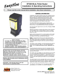
This manual covers service and maintenance procedures
for the following Kohler Whirlpool models:
•
•
•
•
•
•
•
Super Bath™ Whirlpool
Infinity BathTM Whirlpool
CaribbeanT" Whirlpool
Steeping Bath™ Whirlpool
GuardianTM Whirlpool
Barbados™ Whirlpool
Pristme'M Whirlpool
K-1422
K-1482, K-1484
K-802
K-792
K-783, K-784
K-1409, K-1410
K-772
TABLE OF CONTENTS
SECTION 1 GENERAL INFORMATION
INTRODUCTION ...
WARNINGS AND PRECAUTIONS.
SERIAL NUMBER LOCATION
SERVICE AND MAINTENANCE.
COMPONENT LOCATIONS .....
SECTION 2 GENERAL SYSTEM DESCRIPTION
.........
THEORY OF OPERATION
WATER FLOW .....................
TROUBLESHOOTING .... .........
COMPONENT IDENTIFICATION LIST.
SECTION 3 TIMER
THEORY OF OPERATION .....
SERVICING THE TIMER
WHIRLPOOL TIMER CONVERSION.
COMPONENT IDENTIFICATION LIST ..
SECTION 4 POWER PANEL
THEORY OF OPERATION.
SERVICING THE POWER PANEL
COMPONENT IDENTIFICATION LIST.
SECTION 5 WATER LEVEL CONTROL
THEORY OF OPERATION
SERVICING THE WATER LEVEL
CONTROL .............
Breather Valve .......................
Float Chamber
.........
COMPONENT IDENTIFICATION LIST.
Guillen's Enterprises, inc
Original Kohler Parts
guillens.com
800-222-7855
2
3
4
4
5
7
8
8
9
10
11
11
SECTION 6 MOTOR AND PUMP
THEORY OF OPERATION
..... 15
SERVICING THE MOTOR AND PUMP.. 15
ITT MARLOW 60041, 60097 AND 60388-M
MOTOR AND PUMP
15
COMPONENT IDENTIFICATION LIST ... 16
ITT MARLOW 60186, 60187, 60478, 60479,
60660-M, 60661-M, 60457, 60501. 60662-M
AND 60663-M MOTOR AND PUMP .... 16
COMPONENT IDENTIFICATION LIST.. 17
HAYWARD 60660-H AND 60661-H
MOTOR AND PUMP................ 17
COMPONENT IDENTIFICATION LIST.
18
SECTION 7 TRIM KITS
SERVICING THE TRIM KITS ...........
Air Control Assembly ........
Adjustable Jets..
Suction Inlet ...
. ....
COMPONENT IDENTifiCATION LIST ...
19
19
19
20
20
12
SECTION 8 INFINITY BATH FAUCET FITTINGS
COMPONENT IDENTIFICATION LIST ... 21
13
SECTION 9 OLD STYLE TIMERS AND
POWER PANEL ...
. ............... 23
13
13
14
14
Guillen's Enterprises, inc
Original Kohler Parts
guillens.com
800-222-7855
SECTION 1- GENERAL INFORMATION
INTRODUCTION
The purpose of this manual is threefold: to provide
familiarization with Kohler Whirlpool Bath operation:
to provide detailed maintenance and functional checkout instructions; and to provide comprehensive replacement and service parts Information.
This manual contains a general system description,
functional checkout procedures and an identification
of all major components. Theory of operation and
repair information for the individual components are
included in their respective sections.
WARNINGS AND PRECAUTIONS
1. Kohler Company does not assume responsibility
for warranty repairs performed by anyone other
than an Authorized Service Representative (ASR).
2. When servicing the control panel, motor and
pump or any portion of the system where high
voltages may be encountered, ensure power to the
Whirlpool Bath is OFF.
3. All electrical work shall be performed by a qualified
electrician or ASA.
4. Pump motor may operate at high temperatures;
avoid coming in contact with motor shell while
pump motor is operating or shortly after shutdown.
5. After servicing the Whirlpool Bath, always reinstall all safety devices as originally found prior to
repair or service.
6. Local electrical codes may require use of a Ground
Fault Circuit Interrupter (GFCI) on circuits supplying powerto the Whirlpool Bath. Kohler Company recommends the use of a GFCI on all
installations.
7. All finish materials - enamels, acrylic, plating,
etc. - can easily be damaged. Do NOT stand or
place tools in Whirlpool Bath. Kohler Company
will not be held responsible for damage to finish
caused during repair.
8. Modifications, additions or deletions shall not be
made to Kohler Whirlpool Baths.
9. Instructions, drawings and schematics contained
in this manual represent information available at
time of printing. Although every attempt has been
made to keep them as up-to-date as possible,
Kohler Company reserves the right to implement
product changes without prior notice.
10. Kohler Company will not assume responsibility
for product performance or safety where repJace-
ment components or parts other than Genuine
Kohler Replacement Parts or authorized alternates
are used.
11. Kohler Company recommends all gaskets, seals
and O-rings be replaced if removed during service
or inspection procedures.
SERIAL NUMBER LOCATION
The serial number is a 10-character code provided on
each Whirlpool Bath to establish a uniform method of
permanently marking each unit. The serial number is
located on the Whirlpool Bath pipe harness return line
directly above the power panel so it is viSible after
installation with the access panel removed.
All warranty reports and invoices must include the
serial number.
The
•
•
•
•
•
serial number indicates the following;
Manufacturing facility.
The decade in which it was manufactured.
The year of manufacture.
The month of manufacture.
In-plant identification.
Manufacturing Facility Code - The first character
(alpha) in the string of numbers as listed below.
Manufacturing
Facility
Code Pre
Jan. 1, 1983
Code Post
Jan. 1, 1983
Brownwood
Richmond
Spartanburg
Toledo
Wisconsin
C
T
R
R
B
A
0
A
W
S
Decade When Manufactured - The second character
(numeric) in the string of numbers.
Examples; 7 for the 70's, 8 for the 80's, etc.
Year Of Manufacture - The third character (numeric)
in the string of numbers.
Examples: 8 for 78, 1 for 81, 2 for 82, etc.
Month Of Manufacture - The fourth character (alpha)
in the string of numbers as listed below.
Month
January
February
March
April
May
June
Code
A
B
C
0
E
F
Month
July
August
September
October
November
December
Code
G
H
I
J
K
L
Serial Number
,,
__ :.7"
-\l})
-,-TI
LlJ
Figure 1-1. Serial Number Location
In-Plant Identification - The fifth through eighth
characters (numeric) in the string of numbers are used
for in-plant identification.
Follows the eighth
Kohler Whirlpool Baths require a minimum of maintenance for trouble-free operation. Removal and replacement procedures, as well as repair techniques for
the various components of the Whirlpool Bath, are
provided in the following sections of this manual.
• Manufactured pre January 1, 1983. D78A0006/X.
Only commonly used tools are required to service
Kohler Whirlpool Baths, however, a multimeter is
required to test the electrical components of the
system.
Whirlpool Designate Code character of the string as "IX."
Examples:
- D. Wisconsin manufacturing facility.
- 7. Manufactured in the 70's.
- 8. Manufactured in 1978.
- A. Manufactured in January.
• Manufactured post January 1,1983. W83B0006/X.
-
W.
8.
3.
B.
Wisconsin manufacturing facility.
Manufactured in the 80's.
Manufactured in 1983.
Manufactured in February.
NOTE: All Whirlpool serial numbers manufactured
priorto February, 1980 included a "K" prefix indicating
Wisconsin as the manufacturing facility.
Guillen's Enterprises, inc
Original Kohler Parts
guillens.com
800-222-7855
2
SERVICE AND MAINTENANCE
Service should be periormed by an Authorized Service
Representative (ASR).
CAUTION: When servicing the power panel, motor
and pump or any other portion of the system where
high voltages may be present, ensure the power to the
Whirlpool Bath is OFF. If voltage measurements are
required, use caution.
Service and maintenance procedures described in
this manual apply to all models of the Whirlpool Bath.
Although component configuration may differ from
model to model, operation and service are relatively
the same.
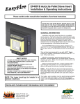
COMPONENT LOCATIONS
Figure 1-2 will help you locate the different components on the various models.
Guillen's Enterprises, inc
Original Kohler Parts
guillens.com
800-222-7855
,
Caribbean
,
4
4':"
5
,-itl . . .
d,
4
5
2
Infinity 00 Bath
Pristine
1_2
2
5
2
-- 1
~~l
"
. I
3
3
Guardian
--t-=_
The Super Bath
1. Adjustable Jet
2. Adjustable Air Control
3. Molor and Pump
Steeping 8ath
II
tt'
,
-~---
3
Barbados
4. Water Suction Inlet
5. Safety Grip Handle
Figure 1-2. Component Locations
3
SECTION 2- GENERAL SYSTEM DESCRIPTION
THEORY OF OPERATION
Each electronically actuated Kohler Whirlpool Bath
consists of five basic components:
• Tub which acts as a reservoir for the water and
provides a location for the whirlpool action.
• Timer which turns the Whirlpool Bath ON and
OFF, and controls the length of time the Whirlpool Bath is in operation.
• Power panel which provides electricity to drive
the motor and pump.
Air
Control
• Water level control which inhibits Whirlpool Bath
operation if there is too little water in the tub.
• Motor and pump which provide the power to
move the water and create the whirlpool action.
Adjustable
WATERFLOW
Basic water flow for the Kohler Whirlpool Bath is
depicted in Figure 2-1. Once filled with water, the
Whirlpool 8ath becomes a self-contained system.
Water is drawn from the tub through the water suction
inlet typically located near the bottom of the tub,
pulled into the pump, and forced back out to the tub
through adjustable jets located in the tub walls.
Air is asperated into the water stream at the jets and
adjusted using the air controls.
This cycle continues as long as the motor and pump
are operating.
Guillen's Enterprises, inc
Original Kohler Parts
guillens.com
800-222-7855
4
o
Legend
D Water
D
Air
Figure 2-1. Water Flow
I
Guillen's Enterprises, inc
Original Kohler Parts
guillens.com
TROUBLESHOOTING
800-222-7855
NOTE: This troubleshooting guide is a general aid only. All electrical
problems should be resolved by an authorized Kohler repair service or
qualified electrician. If the problem cannot be resolved, contact the
installing contractor or the local Kohler branch office.
SYMPTOMS
Pump not pumping.
PROBABLE CAUSES
Low water level in tub
(below jets).
2. Suction air leak.
=
~CO""MENDED ACTION
Fill tub to proper level
2. Motor does not turn.
1. No power to motor.
Tighten all clamps and fittings on
suction side of pump.
Check that all power switches are
on. Be sure fuse or circuit breaker
is properly set.
3. Low water flow.
1 . Suction air leak.
Check that time is set properly.
Tighten all clamp fittings on
suction side of pump.
r- 4. Noisy operation.
5 Motor overload.
2. Discharge jets partially closed
or clogged.
Clean clogged jets.
3. Orifice jet assembly missing.
1. Air leak in suction line.
Install orifice.
Repair leak. Check suction pipe.
Tighten clamps.
2 Restricted suction line due to
blockage.
Remove blockage.
3 Bad beanngs on motor.
1. Motor is improperly connected.
Have electrician replace motor.
Check wir"tng diagram on motor.
NOTE: Electrical work must be 2. Low voltage due to undersized
done by a qualified electrician
wire or low voltage.
or an authorized Kohler service
representative.
6. Water leaking along pump
shaft.
7. Timer display lights with set
time, but pump does not start
when START/STOP activated.
8. Pump always on while power
applied to system.
9. Pump running slow and erratic
with growling noise.
10. Timer sets time and counts
down, but pump will not run.
1. Defective timer.
Check with volt meter. Increase
size of supply wire. Report low
supply voltage to power company.
Voltage at motor must be within
10% of motor nameplate voltage
during operation.
Disassemble pump and replace
seal.
Replace circuit board.
2. Faulty timer cable.
Replace cable.
3. Faulty re!ay.
1 Defective relay (lOW or no
v?~tage at rel~y input).
Low voltage to pump from high
voltage side of relay.
Replace relay.
Replace relay.
2. Short in timer cable.
Replace cable.
Replace relay.
1. Worn pump seal.
1. Relay defective.
Check voltage at pump. Replace
relay if less than line voltage.
-
_. - -
5
TROUBLESHOOTING (Continued)
.. - SYMPTOMS
~-
PROBA BlE CAUSES
RECOMMENDED ACTION
~.
11. Pump runs and trips GFCI
breaker.
Guillen's Enterprises, inc
Original Kohler Parts
guillens.com
800-222-7855
12. Whirlpool starts itself.
1. Bad bearing in pump.
Replace pump.
2 Loose electri cal connections.
Secure all contacts.
3. GFCI trips at less than 5
milliamperes
Replace GFCI breaker.
4. Ground fault in system.
Disconnect wires from relay. Check
resistance between case and
terminals. If below 100 kilohms,
replace relay.
1. Not on a separate circuit.
Wire electrical supply on separate
circuit.
2. Power outag e, lightning voltage
Replace 60347 printed circuit
board.
spike, transi ent noise.
13. Whirlpool timer flashes "L"
when START/STOP pushed.
._- ....
14. No display/timer dead.
3. Contaminants (sawdust, metal
shavings) on 60347 timer board.
Clean or replace 60347 printed
circuit board.
4. Faulty relay.
Replace relay.
1. Water in tub not 2" above jets.
Add water.
2. Three-hole retainer in jet
assembly in wrong location.
See trim kit installation
instructions.
3. Air lock in breather.
Clean breather orifice and observe
water to fill up into clear tube equal
to water level in tub.
4. Obstruction in line from threehole retainer to float control.
Remove cover of float control and
run wire to orifice hole in jet
assembly.
5. Failure on 60 347 printed circuit
board assem bly or in timer
cable.
Disconnect float control plug from
power pack. If timer still flashes
"L", replace 60347 timer board.
Also check control cable for nails .
1. Face plate n ot making contact
Masonry box not flush with
finished wall (see installation
instructions for 60350 timer).
~
with foils for set time and
STARTiSTO P.
2. No output 0 n secondary side of
Replace transformer.
transformer (6-14VDCi.
15, Timer LED missing legs.
3. Timer cable connection loose or Secu re connection or replace
damaged at timer prongs.
60318 timer cable.
Replace timer 60347 printed circuit
1. Timer circuit ry defective.
board.
~~~-
16. Whirlpool flashes "L" with
tub full.
1. Three-hole retainer in jet
assembly in wrong location.
See trim kit installation
instructions.
2. Water level sensor float
Invert float.
reversed.
17. Whirlpool does not flash "L"
with tub empty.
1 Level float pi ug disconnection.
18. Pump runs but no whirlpool
action.
1. Brass orifice s missing behind jet
assembly.
Insure connection.
~------
- - - -
~~.~
Install orifices.
2. Suction bloc ked._ _ _ _ _ _-'C:'I"'e"a"rsucti":'o"n.'-_ _ _ __
6
COMPONENT IDENTIFICATION LIST
5_
,
1
,
('
2
~
00
7
8
•
~
Item No.
1
2
3
4
Description
Timer
Power Panel
Water Level Control
Motor and Pump
.- Depends on model
Quantity
Item No.
Description
Quantity
1
1
1
1
5
Adjustable Air Control
Adjustable Jets
Water Suction Inlet
Timer Cable
2
6
7
8
1
1
Figure 2-2. Whirlpool Bath
Guillen's Enterprises, inc
Original Kohler Parts
guillens.com
800-222-7855
•
7
Guillen's Enterprises, inc
Original Kohler Parts
guillens.com
800-222-7855
SECTION 3- TIMER
THEORY OF OPERATION
Power for the timer (Fi Q Ure }.-1), provided by the
power panel, is between a 'I\~!!6 G VDC and can be
measured across pins 1 and 5 of connector P1 with the
plug connected and the system activated. The water
level control is connected to the timer through pin 3 of
connector P1. When the water level is too low for safe
operation of the Whirlpool Bath, an "L" appears on the
digital display. The water level control also prevents
Whirlpool Bath operation when the water level is too
low.
5
sw,
., ~
:fLi
~5
~
,~,::k.~ T.
White
Red
Green
Power
Panel
-
Whirlpool operating time is set by closing the contacts
of SET TIME pushbutton SW1 The last operating time
is shown on the digital display. Pressing and holding
SW1 allows selection of running time, from 1 to 19
minutes. When SW1 is released, the time setting IS put
into memory and controls the length of time the
Whirlpool Bath will operate.
Start/Stop pushbutton SW2 turns the Whirlpool Bath
ON and OFF causing the microprocessor to activate
and deactivate the relay in the power panel. The
Whirlpool Bath automatically turns OFF when time on
the digital display runs out or if the water drops below
the minimum level for safe operation.
Pushbutton SW1 must be pressed and time must be
displayed before pushbutton SW2 will activate the
Whirlpool Bath. The time displayed goes off after 30
minutes if the Whirlpool Bath is not turned ON.
Pushbutton SW1 will not change the set time if the
Whirlpool Bath is running, but will change the time
when the "L" is flashing.
SERVICING THE TIMER
The timer printed circuit board is nonrepairable.
Should it become defective, replace using the following procedure (refer to Figure 3-3):
CAUTION: Before servicing the timer, ensure power
to the Whirlpool Bath is OFF.
1. Loosen two setscrews on bottom of control plate.
Figure 3-1. Timer Board
2. Remove control plate.
Figure 3-2. Timer Schematic
B
3. Remove screws securing timer circuit board and
bracket to wall box.
4. Remove timer circuit board and bracket.
5. Disconnectthe timer cable from timer circuit board.
NOTE: The circuitry on the timer circuit board can
be damaged if not properly handled. Do NOTtouch
the components on the board. Handle the board by
its edges or by the attached bracket.
Tub
Model
K-783
Old
Timer
9680/81
K-792
9680/81
K-802 9680/81
K-1409 9680/81
K-784 9680/81
K-1402 9680/81
K-1410 9680/81
K-1422
K-1482
6. Replace in reverse order.
7. After replacing timer circuit board, check clearance
between pushbutton actuator and contact. Pushbutton should actuate contacts when pressed.
NOTE: It is important the timer circuit board and
bracket be installed flush with the finished wall.
Failure to do so will result in poor contact between
the pushbutton actuator and circuit board switches.
8. If adjustment is necessary, use shims to bring timer
circuit board and bracket away from wall box and
within reach of pushbutton actuator.
K-772
New
Timer
60350
60350
New Power Old Power
Panel
Panel
-
60300
60300
60350
60350
60350
60233
60101
60101
60233
60229
60350
60300
60300
60300
60325
60350
60300
60229
60350
60350
60350
60325
-
60102
60325
60325
The timer and power panel are changed using the
following procedure:
CAUTION: Before beginning conversion proced ures,
turn Whirlpool Bath power OFF.
1. Disconnect 110 VAC from incoming powersupply
connection.
2. Remove 90° elbow from motor.
3. Disconnect 110 VAC cable at motor connections.
WHIRLPOOL TIMER CONVERSION
Whirlpool Baths equipped with old timers, Model 9680
(timer without digital display) and Model 9681 (timer
with LCD), should be replaced if defective with Model
60350 LED Timer. Use Figure 3-3 to identify the timer
currently being used on the Whirlpool Bath.
When changing from an old style to a new style timer,
it is also necessary to replace the power panel. The
following table will help identify the timer and power
panel.
4. Remove power panel from copper tubing by
removing screws and nuts attached to "U" clamps.
NOTE: If new timer cable cannot be installed
between power panel and timer location follow the
procedures listed below.
5. Cutexisting timer cable as close to existing power
panel as possible.
6. Attach new power panel to copper tubing by
attaching "U" clamps, screws and nuts.
Guillen's Enterprises, inc
Original Kohler Parts
guillens.com
800-222-7855
I,
I:]
IL
o
----,
Model 9680 Timer
Model 60350 Timer
Model 9681 Timer
Rgure 3-3. Timer Control Plates
9
7. Splice existing timer cable to new timer cable on
new power panel. Cut to size before splicing.
8. Solder and insulate cables as required.
9. Install replacement 90 0 elbow (supplied) into
motor casing.
10. Install 110 VAC motor leads through elbow and
attach to motor connections.
11. Connect 110 VAC leads to incoming powersupply
line connection.
2. Carefully remove timer board from masonry box
and remove all cable connectors attached to
backside of timer board.
3. It new timer cable has not been installed between
power panel and timer, cut new cable with connector plug, leaving about 12 inches ot cable.
4. Cut oft cable connectors on existing cable near
masonry box.
5. Splice 12 inch new cable to existing timer cable.
6. Solder and insulate as required.
NOTE: Disregard level plug connection on side of
new power panel.
7. Connect new cable to timer board.
8. Install timer board and faceplate as specified in
timer installation procedures.
1. Remove four screws from faceplate of old timer.
COMPONENT IDENTIFICATION LIST
Guillen's Enterprises, inc
Original Kohler Parts
guillens.com
800-222-7855
4
y.
r
----.........
Wl
0 0
00
~
,,~,
3
~
"--
5
~-
"'--.
Item No.
Description
Quantil}!'
Item No.
Description
Quantit}!'
1
2
3
Masonry Box
Timer Cable
Timer Circuit Board
4
1
1
5
Machine Screw
Control Plate
Gold-Chrome Insert
4
1
2
6
Figure 3-4. 60350 Electronic Timer
10
2
----
~-..:.-:::::..-
c
~
SECTION 4- POWER PANEL
THEORY OF OPERATION
Replacing the Transformer
The power panel connects the 120 VAC input to the
operating circuits of the whirlpool Incoming voltage is
connected to the motor and pump through a solid
state relay_ A transformer and diode steps down and
rectifies the incoming voltage for use by the timer
circuitry.
1. Remove power panel cover by removing four
screws.
2. Mark and remove all transformer leads.
3. Remove two screws securing transformer to power
panel.
When the relay is closed, 3 to 5 VDC can be read
across contacts E and F.
4. Remove transformer.
5. Replace in reverse order. Make sure all connections
are secure.
Aschematic of the power panel is shown in Figure 4-1.
SERVICING THE POWER PANEL
Replacing the Relay
The power panel contains two replaceable components, the transformer and solid state relay. They can
be replaced using the following procedure (refer to
Figure 4-2):
1. Remove power panel cover by removing four
screws.
2. Mark and remove all leads attached to relay.
CAUTION: Turn Whirlpool Bath circuit breaker OFF
or otherwise disconnect power from unit before performing any maintenance on power panel.
3. Remove relay by removing two screws securing
relay to power panel.
4. Replace in reverse order. Be sure heat sink compound (supplied) is applied across complete base
of relay before installation.
Use a multimeter to check power before replacing any
components.
Guillen's Enterprises, inc
Original Kohler Parts
guillens.com
800-222-7855
J
- - - - - - --I
,
:;~qD~== L~;'
~
SEC'~" '''v.,-----',~
L.evel
Sw.
~.
I
PRIMARY
12.0",
r~1
III
I
To
Molor
-~
F
c
Figure 4-1. Power Panel Schematic
11
COMPONENT IDENTIFICATION LIST
Guillen's Enterprises, inc
Original Kohler Parts
guillens.com
800-222-7855
Item No.
Description
Quantity
Item No.
1
2
3
4
Electrical Box
Electrical Box Cover
Electrical Box Gasket
Machine Screw
Receptacle
Machine Screw
Transformer
1
1
1
4
1
4
1
8
9
10
11
12
13
14
5
6
7
Figure 4-2. Power Panel
12
Description
Wiring Harness
Relay
Wiring Harness
Hanger
Machine Screw
Bushing
Machine Screw
Quantity
1
2
5
2
2
SECTION 5- WATER LEVEL CONTROL
THEORY OF OPERATION
The water level control inhibits the operation of the
Whirlpool Bath if there is too little water in the tub.
Figure 5-1 illustrates how the water level control
interfaces with the remaining components of the
Whirlpool.
A reed switch in the float chamber assembly, normally
closed when the water level is low, grounds one of the
pins of the microprocessor causing a flashing "L" to
appear on the digital display.
When sufficient water is in the tub, the float in the float
chamber assembly rises causing the reed switch to
open. Because the microprocessor pin is no longer
grounded, the motor and pump can be engaged when
the "L" stops flashing and a time appears on the digital
display. A 10-second delay may be experienced after
the reed switch opens and the "L" stops flashing.
A breather valve located above the float chamber
assembly allows ai r to escape as the chamber fills with
water. The float chamber assembly is connected to the
tub by a copper tube. Water from the tub enters the
tube through an inlet located in one of the jet assemblies.
Guillen's Enterprises, inc
Original Kohler Parts
guillens.com
800-222-7855
NOTE: Location of the three-hole retainer is important
to the operation of the water level control. Refer to
Section 9 Trim Kits for proper location.
SERVICING THE WATER LEVEL CONTROL
The water level control consists of a breather valve,
float chamber assembly and connecting tubing. Under
normal operating conditions these parts should only
require occasional cleaning. However, should they
become defective they can be replaced using the
following procedures.
Breather Valve
The breather valve can be removed and cleaned using
the following procedure (refer to Figure 5-2):
CAUTION: When replacing breather valve, ensure that
the flexible plastic tubing is not kinked or bent. This
could obstruct air flow.
1. Use screwdriver to gently pry breather valve from
securing bracket located on underside of tub.
Air Vent
Hole
Securing
Bracket
/'
Breather Valve
//
Jet Assembly
(Inside Tub)
\
___ Flexible Plastic
Tubing
Float Chamber
A-I[--</ ....mblY
Copper
/'
~.
/~~>//
rr~/
Tubing
Waler Level
Inlet
'==~ ~'--<ll
WlJ/
III (
V
Power
Figure 5-1. Water Level Control
13
2. Disconnect flexible plastic tubing from float chamber assembly.
COMPONENT IDENTIFICATION LIST
3. Remove breather valve and flexible plastic tubing.
1_~
4. Clean flexible plastic tubing and breather valve
port. Be sure to remove any dirt or other foreign
objects that may obstruct flow of air.
5. Replace in reverse order.
2-'~
Float Chamber Assembly
U
Thefloat chamber assembly can be removed from the
water level control by using the following procedure
(refer to Figure 5-2):
' - $ !,'
1. Disconnect copper tubing from bottom of float
chamber assembly.
2. Disconnect level control plug from power panel.
,
,
2J
'---....0
-------t:)
3. Remove two screws securing float chamber assembly to harness bracket.
4. Remove flexible plastic tubing connecting breather
valve to float chamber assembly.
6
,
5. Remove float chamber assembly.
'''et /'
6. Replace in reverse order.
The float chamber assembly can be disassembled for
cleaning or service by using the following procedure
(refer to Figure 5-2):
@~
.
~
1. Remove level switch sub assembly.
2. Remove C-clip from level switch sub assembly.
3. Remove float and gasket from level switch sub
assembly.
4. Clean float chamber, level switch sub assembly and
float. Clean inlet and outlet ports of float chamber.
Ensure there are no obstructions to water flow.
5. Replace in reverse order.
6. When reassembling float chamber assembly, ensure grooved portion ottloat is located at bottom of
level switch sub assembly.
Guillen's Enterprises, inc
Original Kohler Parts
guillens.com
800-222-7855
14
Item No.
Description
Quantity
1
2
3
4
5
Breather Valve
Flexible Tube
Spring Clip
Level Switch Sub Assembly
Gasket
Float
Float Chamber
Sleeve
1
1
1
1
1
1
1
1
6
7
8
Figure 5-2. Water Level Control
Guillen's Enterprises, inc
Original Kohler Parts
guillens.com
800-222-7855
SECTION 6- MOTOR AND PUMP
THEORY OF OPERATION
4. Remove motor and pump.
The motor and pump work as a unit; the motor
provides the drive power for the pump impeller.
S. Disconnect motor power cord from power panel.
The whirling action of the impeller creates a vacuum,
pulling water into the inlet port. The incoming water is
forced through the impeller and out through the water
harness.
Adjustable jets, located on the sides of the tub, provide
outlets for the circulating water and serve to divert the
flow of the water for more effective whirlpool action.
Figure 6-1 illustrates how air is asperated into the
water stream as the water passes through the adjustable jets. The amount of air mixed with the water is
controlled by the adjustable air control located on top
of the tub.
6. Replace in reverse order.
Once the motor and pump has been removed, determine which model had been installed. Follow service
procedures for that model only.
ITT MARLOW 60041, 60097 AND 60388-M
MOTOR AND PUMP
The ITT Marlow 60041,60097 and 60388-M motor and
pump can be disassembled for service using the
following procedure (refer to Figure 6-2):
1. Removescrews securing casing to motor. Remove
casing.
SERVICING THE MOTOR AND PUMP
2. Lift off diffuser and gasket.
The motor and pump should be removed from the
Whirlpool Bath for all service and maintenance activities, Removal and replacement can be accomplished
using the following procedure:
3. Hold motor shaft by inserting screwdriver into slot
provided in motor casing; or remove motor end
cover and hold shaft with an open end wrench.
CAUTION: Turn Whirlpool Bath circuit breaker OFF
or otherwise disconnect power from unit before performing maintenance on motor and pump.
1. Disconnect pump from suction and harness tubes.
2. Disconnect ground strap.
CAUTION: Be careful not to strip threads in tub.
3. Remove bolts securing motor and pump to tub.
Air
4. Rotate impeller counterclockwise and remove.
5. Slide rotating member of seal assembly off impeller
shaft.
6. Remove diffuser O-ring and seal plate gasket.
7. Remove screws and lockwashers securing seal
plate and bracket to motor housing. Remove seal
plate and bracket.
8. Remove stationary members of seal assembly by
pushing out from behind seal plate and bracket.
Use only fingers, not a screwdriver or other sharp
object which may damage components.
9. Check impeller, diffuser, diffuser O-ring, gasket
and seal assembly. If any item is damaged or worn,
replace it. Impeller, casing and diffuser are a
matched set; replace at the same time.
10. Clean impeller and ali seal assembly cavity surfaces thoroughly before reassembling.
11. Secure seal plate to motor housing.
12 Install stationary members of seal assembly into
the seal plate. Lubricate gasket with clean water
only.
Air/Water
Mixture
CAUTION: When installing seal assembly members, do not use a screwdriver or other sharp
object which may damage ceramic ring.
Figure 6-1. Water/Air Mixture
13. Seat stationary members firmly, using finger pressure only.
15
14. Slide rotating member of seal assembly onto
impeller shaft. Lubricate with clean water only.
and pump can be disassembled for service using the
following procedure (refer to Figure 6-3):
15. Ensure grooved portions of rotating member are
located over raised portions of impeller shaft
1. Remove screws secunng pump casing to face
plate. Remove casing.
16. Hand tighten impeller onto motor shaft.
2. Hold motor shaft by inserting a screwdriver into
slot provided in motor casing; or remove motor
end cover and hold shaft with an open end
wrench
17. Place diffuser over Impeller with word "TOP" at
top. Stop lug will be in 6 o'clock position. Ensure
the O-ring is securely in place.
18. Lubricate with water. Then place gasket in groove
on seal plate and bracket Ensure gasket is sealed
properly.
19. Replace pump casing and secure in place.
3. Rotate impeller counterclockwise and remove.
4. Slide rotating member of seal assembly off impeller shaft.
5. Remove face plate O-ring.
6. Remove face plate from motor housing.
ITT MARLOW 60186, 60187, 60478, 60479,
60660-M,60661-M,604S7,60S01,60662-M
ANO 60663-M MOTOR ANO PUMP
7. Remove stationary members of seal assembly by
pushing out from behind plate. Use only fingers,
not a screwdriver or other sharp object which may
damage components.
The ITT Marlow60186, 60187, 60478, 60479, 60660-M,
60661-M, 60457, 60501, 60662-M and 60663-M motor
8. Check impeller, O-ring and seal assembly. If any
item is damaged or worn, replace it. Impeller and
COMPONENT IDENTIFICATION LIST
ITT Marlow 60041, 60097 and 60388-M Motor and Pump
Guillen's Enterprises, inc
Original Kohler Parts
guillens.com
800-222-7855
12
9
5
•
3
Item No.
Description
Quantity
Item No.
1
2
3
4
Casing
Gasket
Diffuser
Impeller
Seal Assembly
Gasket
Screw
1
1
1
1
1
1
4
8
9
10
11
12
13
5
6
7
Figure 6-2. Motor and Pump
16
Description
Lockwasher
Seal Plate
Screw
Slinger
Motor
O-Ring
Quantity
4
1
8
1
1
1
COMPONENT IDENTIFICATION LIST
ITT Marlow 60186, 60187, 60478, 60479, 60660-M, 60661-M, 60457, 60501, 60662-M and 60663-M Molorand Pump
Guillen's Enterprises, inc
Original Kohler Parts
guillens.com
800-222-7855
8
,
1
7
----
~
4
3
--~
Item No.
1
2
3
4
Description
Quantity
Item No.
Description
Quantity
1
6
1
1
5
Seal Assembly
Face Plate
Slinger
Motor
1
1
1
1
Casing
Screw
O-Ring
Impeller
6
7
8
Figure 6-3. Motor and Pump
casing are a matched pair; replace both at the
same time.
g, Clean impeller hub and all seal assembly cavity
surfaces.
10. Install face plate on motor housing.
11. Install stationary members of seal assembly into
face plate. Lubricate O-ring with clean water only.
CAUTION: When installing seal assembly members, do not use a screwdriver or other sharp
object which may damage ceramic ring.
12. Seal stationary members firmly using finger pressure only.
13. Slide rotating member of seal assembly onto
impeller shaft. Lubricate with clean water only.
HAYWARD 60660-H AND 60661-H
MOTOR AND PUMP
The Hayward 60660-H and 60661-H motor and pump
can be disassembled for service using the following
procedure (refer to Figure 6-4):
1. Remove screws securing pump casing to seal
plate. Remove casing.
2. Hold motor shaft by inserting a screwdriver into
slot provided in motor casing; or remove motor
end cap and hold shaft with an open end wrench.
3. Rotate impeller counterclockwise and remove.
4. Slide rotating member of seal assembly off impeller shaft.
5. Remove motor end cap.
14. Ensure grooved portions of rotating member are
located over raised portions of impeller shaft.
6. Remove screws securing seal plate to motor
housing.
15. Hand tighten impeller onto motor shaft.
7. Remove stationary members of seal assembly by
pushing out from behind seal plate. Use only
fingers, not a screwdriver or other sharp object
which may damage components.
16. Install O-ring on face plate.
17. Replace pump casing and secure in place.
17
8. Remove slinger from motor shaft.
9. Check impeller, D-ring, shaft sleeve and seal
assembly. If any item is damaged orworn, replace
it. Impeller and casing are a matched pair: replace
both at the same time.
CAUTION: When installing seal assembly members, do not use a screwdriver or other sharp
object which may damage components.
11. Install slinger on motorshaft. Ensurethatflange of
slinger is facing threaded end of shaft.
16. Press assembled stationary members of seal assembly into seal plate. Lubricate with clean water
only. Seal assembly should be pressed in with
D-ring toward motor and exposed face of the
ceramic ring toward impeller.
12. Install D-ring on ceramic seal member. Ensure it is
properly seated.
17. Slide rotating member of seal assembly onto
impeller shaft. Lubricate with clean water only.
13. Press ceramic ring into clear plastic retainer.
18. Hand tighten impeller onto motor shaft.
14. Attach seal plate to motor housing.
19. Install D-ring on seal plate.
15. Install D-ring on cut ridge of clear plastic retainer.
20. Replace pump casing and secure in place.
10. Clean impeller hub and all seal cavity surfaces.
COMPONENT IDENTIFICATION LIST
Hayward 60660-H and 60661-H Motor and Pump
Guillen's Enterprises, inc
Original Kohler Parts
guillens.com
800-222-7855
,
e?~1
Item No.
1
2
3
4
5
6
7
Description
Screw
Casing
D-Ring
Impeller
Seal Assembly
Seal Plate
Slinger
Quantity
Item No.
Description
Quantity
6
8
9
10
11
12
13
Motor
Screw
End Cap
Insulating BUShing
Insulating Bushing
Nut
1
4
1
2
2
1
1
1
1
1
Figure 6-4. Motor and Pump
18
6
•
Guillen's Enterprises, inc
Original Kohler Parts
guillens.com
800-222-7855
SECTION 7- TRIM KITS
SERVICING THE TRIM KITS
Trim kit components are designed for long life. However, if one needs to be replaced, use the following
procedures (refer 10 Figure 7-1):
3. Disassemble assembly into ball, O-ring, retainer
and plastic insert bearing.
4. Remove trim ring.
5. Replace parts as required and clean all surfaces
before reassembly.
Air Control Assembly
NOTE: Some retainer assemblies have three 1/4"
holes drilled into them. These holes are required
for proper operation of water level control. If
retainer with three holes is being replaced, it must
be replaced with a similar retainer. Three hole
retainers are located on Whirlpool Baths as
follows:
The air control assembly is serviced using the following procedure (refer to Figure 7-1):
1. Raise trim cap and remove setscrew located 'In a'rr
control body_
2. Unscrew control knob.
3. Replace parts as needed and clean all surfaces
before reassembly.
Whirlpool
Model
GuardIan K-783-S,
Steeping Bath K-792-S,
Caribbean K-802-S,
Barbados K-1409
Guardian K-784-S,
Barbados K-1410
The Super Bath K-1422
4. Install setscrew into air control body, leaving
several threads exposed outside body.
5. Place trim cap over air control body.
6. Screw knob into body about eight turns.
7. Lift trim cap and tighten setscrew until it makes
contact with knob shaft.
8. Back setscrew off 1/4 turn.
9. Check knob for proper installation by turning
counterclockwise until it stops. Knob shOuld not
unscrew from air control body.
10. If knob unscrews from body, remove knob and
trim cap. Repeat steps 6 through 10. increasing
number of turns in step 7 by 1/2 until knob no
longer unscrews from air control body.
11. Apply small amount of RTV sealant to underside
of trim cap.
12. Line up dimple in trim cap with setscrew in air
control body.
13. Carefully push trim cap onto air control body.
14. Fill any gaps between trim cap and control body
with RTV. Remove any excess RTV from around
air control assembly.
Adjustable Jets
The adjustable jets are serviced using the following
procedure (refer to Figure 7-1):
1. Remove two screws securing assembly to jet
housing.
2. Pull on center of ball and remove assembly from
housing. Assembly may be tightly sealed. If necessary, use small Phillips screwdriver in screw
hole to remove assembly.
.
Infinity'~ 00
K-1482
-
Location of Jet Housing
With Three Holes·
Left Rear
Right Rear
1st Jet Housing Clockwise
From the Drain
Left of Suction Hood
Location IS referenced from a normal seating position
In
the tub.
6. Remove dirt, grease, moisture and RTV from jet
housing flange.
7. Apply RTV sealant to underside lip of trim ring.
S. CarefUlly snap trim ring into flange on tub. Ensure
that dimples in trim ring align with notches in jet
housing.
9. Apply light film of lubricant to two a-rings and
plastic insert bearing.
10. Install a-rings on retainer. One is installed inside,
the other in groove on outside of retainer.
11. Assemble ball and plastiC insert bearing into
retainer.
12. Insert ball and retainer into jet housing, being
careful not to drop plastic bearing into housing.
NOTE: The retainer assembly with three 1/4"
holes must be installed so hole for water level
control is toward bottom of tub and aligns with
hole in jet housing. Water level control hole should
be free of all RTV, dirt and lubricant and be
completely unobstructed to ensure proper water
level control operation.
19
13. Align screw holes and secure retainer to jet
housing.
1 Remove screw securing suction hood and screen to
inlet housing.
14. Tighten screws until ball moves freely with slight
side to side pressure.
2. Remove hood and hair screen.
3. Replace any parts as necessary and clean all
surfaces before reassembly.
4. Fit hair screen into groove on back of hood.
Suction Inlet
The water suction inlet is serviced using the following
procedure (refer to Figure 7-1):
5. Attach screen and hood squarely to inlet housing
Ensure riveted portion of screen is located toward
bottom of tub.
6. Secure hood and screen into place.
Guillen's Enterprises, inc
Original Kohler Parts
guillens.com
800-222-7855
COMPONENT IDENTIFICATION LIST
.--::::.-.
Item No.
Description
Quantity
1
2
3
4
Control Knob
O-Ring
Trim Cap
Setscrew
O-Ring
Screw
Retainer
2
2
2
2
4
2
1
5
6
7
Item No.
8
9
10
11
12
13
14
Figure 7-1. Trim Kits
20
Description
Quantity
O-Ring
Directional Ball
Insert Beari ng
Trim Ring
Screw
Suction Hood
Hair Screen
1
1
1
1
1
1
•
SECTION 8- INFINITY BATH FAUCET FITTINGS
COMPONENT IDENTIFICATION LIST
Guillen's Enterprises, inc
'_~
)
~:;..,-:Original Kohler Parts
guillens.com
800-222-7855
'-0
'--1
4_~
-,--
'-@
I
(4~
, __ L_
------------
Item No.
1
2
3
4
5
6
7
8
9
10
11
Description
Cap
O-Ring
Screw
Handle
Lock Ring
Bonnet
O-Ring
O-Ring
Washer
Stem
Plunger with Seat Washer
and Screw
Quantity
Item No.
2
2
2
2
2
2
12
13
2
2
2
2
2
14
15
16
17
18
19
20
21
22
Description
Seat Washer
Screw
Sleeve
Renewable Seat
Lift Knob
Diverter Replacement
lift Knob
Lift Rod
Retainer Cap
Retainer
Escutcheon
Quantity
2
2
2
2
1
1
1
1
1
1
1
Figure 8-1. Faucet Fittings
21
COMPONENT IDENTIFICATION LIST
r -- _
Guillen's Enterprises, inc
Original Kohler Parts
guillens.com
800-222-7855
' ____ 3
')
I
/'
2
I,.,c
IIi.
r
)
1, ~
I
,- l'
,
6
1
1-
J
16-...... ----
Item No.
1
2
3
4
5
6
7
8
9
10
11
12
13
14
15
Description
Screw
Hood
Nut
Lift Rod
Quantity
Item No.
Description
Quantity
2
1
1
16
17
18
19
20
21
22
23
24
25
26
27
28
29
Ell & Tube SA
Nut
1
1
1
1
1
1
1
1
1
1
1
1
1
1
Lift Rod
Safety Rod
Nut
Washer
Link
Spring
Nut
Gasket
Clamp
Tube
Clamp
1
1
1
1
1
1
1
1
1
1
Figure 8-2. Drain FIttings
22
Gasket
Tee
Gasket
Nut
Drain Ell & Tube
Gasket
Strainer
Lift Toggle
Nut
Stopper
O-Ring
Tailpiece
SECTION 9- OLD STYLE TIMERS AND POWER PANELS
t50~"
"O~,
'e,
!
------Tl
•
_0
,
, '.,
~
'"
.''4..
,
I
"
Ie .,.'"
:
.
I
...
...
"
I
,
"I.~'"
I
'~"'~~7.
,
• '. L"
~
l
,0,
----! I j ;
~
.1 ,
,.
~
M
"i
I
'
~
,
~
N
'"
_
...
••
'".tit.
'
~t
..".
.. ..
t~'" . .. '~J
•
,
,
l; "
I
"
'"
"
0
I',
~
'.
$"
.-., "'1
r
'1
.
I~-"
¢'
"'Mrl'
;!
,,1,,'
..
•
I~. ~
,
I
"
~
yo
,,
~ @,.co.
., H
M'"
,--Tl,.. ... ""''" " ~
'"
e
(.
~
"
.
L:.;
..
.
..
le-
l---=:J'J'q
'
U"
'
Vl'---------'"
".'~~.
I
I
'"
.
"
y"~"~.'8
~
VO~
~,...~ur"c~
i---T!
,
,
,e
~
M
"1.1"'0
"'01.<'07 :l<.JMprR
, "
,
,
=
®<~;J;
'0
"'
'M
:
. ,.-",..,
~. ,,~,
-,
'M
< • '" .0"
~
CQM .. " ...
<!,.----
Agure 9-1. 9680
Non-LC~
Timer Schematic
Guillen's Enterprises, inc
Original Kohler Parts
guillens.com
800-222-7855
23
--
,. ",,-S,s,.""''''
"'''".
..
M,
,'"
•• ' ,'',:'0'''.' ''''' 1
+
IO .. ~...{I0 . .
"'
"'
'-.0'
"
,."
"
'
H
"
eo
e,
e,
'
"" 10
p,~
"'''
,
"u,.w "'....
,., ..
'O~
,~
..
,
..- ,,'
"OD"''' .,;.,,1
".;-", ;..~,-, ".;
L "';.
... ~C"
"'C'w
~
I
MFl:; '-<C.
..
t l l """
O.
J
-..
~'Q""
,.
c,Ct;>""-"
"'~
j
....
I
I~O" Y"W '''''-
""S """k,,""""'''''
1
r
,-"-,,.,,,,,
WI~'"''
0'
.'",FC"'V
"
_Iuf~!>"
C4
---
"-"'''-'''''- """"~D
"
~,~
"'''.
--
,
.-
."
",
-
..
"
DI
""'"'"",,"'
"',a"'~,
,.,.~
,
00
sc
TR-""5""""'S
"'~
"t,
Q~
"
"""'i ..,""-u ~"o~
~...,
Guillen's Enterprises, inc
Original Kohler Parts
guillens.com
800-222-7855
.... "'."
...,....,,'" ""'"ff
.oJD,
"' .. ~
"'-, MC,~-
..
liD.
N'~"
Cb_</~,o_e"
<.
,~5
CA-
"",',er
1<-. Co """"" ..."
Z~"U
I)
f)'ODC
_1m;" -.;;;, ,;.
_
[f)
Figure 9-2. 9680 Non-LCD Timer Component Diagram
24
3."_,<><0
...
,
I1
r"t:t
,. " ~ ,'"
I
'''' •
~ ~"~"<4UC'"
j";L"""'.JUIoI_
~I-------
''''''''
I
, .. I "
, I
I
Figure 9-3. 9681 LCD Tlmer Schematic
Guillen's Enterprises, inc
Original Kohler Parts
guillens.com
800-222-7855
25
-.
... c~ "...,
aF
~._"". ~O>,
TC,..,.1A'i4
"'. I .", 0'0 ~'.' T"
H
..
0'
0'
0'
OP,."rr~·'-''''''
TPU ,,,. , " . " . ' . .
, ,
,"""
'''''''''-''
~,.
..
"', "" -",
0,
00
..
'0/(1<,"',,,,,
"
'''''~
.,." Y;w
o~
~,
,
'O __ "WIC . .
,
0"
'"
IO~
r." -...".
-
_
",DD~""
,vD.
~
-..
"W ,.0"
0,
9/</
j.u
.,
0,
......
..
,0
,0
I I -'
C-<P~C.''''<>R~
V~LU'"
""''''' ",
"
~
-.' -.
-.. --....
'of ~5"
"
T~I="'""
'0
"'''-'.3~D~
".u ...~~ .....
00
'''',.,....,.,00'''''''''
IC-'
,
"'
".
""'-,~
~-~~-".-
'<-5
¢Jo. ~"". ~...-
'"'
CD-
,~-,
".
~,>,,,
"'
~D-"'~~·8.
~."'u
~ _~~""
'''.~
Guillen's Enterprises, inc
Original Kohler Parts
guillens.com
800-222-7855
~"
..,
P,ON
,"v
"~_ F
"
Figure 9--4. 9681 LCD Timer Component Diagram
$,
II~
'" n
;::r,",
! ~~~
I
1~1,t
i ,~!
"l
IC~",,,
:~ -,0,
'?
I
R
L_
,'~
"
~
--
~.~
"f-ii
f'
- - - - - - - - ---
,
-II
'f
vo .. ~ ..
""'" "~,,,,',., "~Q'~ ," ".
® ~~';'; ~~';;:,,~'~ ~:"~d':'~~M
.".~ ",,, ~
-- {"
WH' _ _ _
~
"
u
" - {TO MOTOR
,,~,-
Jf'''-
~
Figure 9-5. 9680/9681 Tlmelll - Power Panel Wiring Diagram
26
LINE
<'-
""'U~I~Y'llU
£uc<""-v~
1><: ..."y
~7~"7,,,~ ~
--~
.,..,...."",.a
,,7~"'~"'"
<IAIOa>W~"CR~
P<""F?""_~
q.!Hl"'~
p
"/~~
lin",·",
~~E.
".$",-"
,>IJ ",,001
7°/_1/.
~
~M-""~'1't"
.... c ,.
"M~
Figure 9-6. 9680/9681 Time rs - Power Penel Schemellc
. 'f'l"
'" '""'- 'i'
~
,,~,
Guillen's Enterprises, inc
Original Kohler Parts
guillens.com
800-222-7855
.ft~O
,e, ";;,,
r'i-
~/
-""
,
,
d
~
0-<l
,
,,
,,
'
~
we
"
D2~K~
~K
e,S$R 1
~" ,
~~'F
so.
'" ,
'"
~
•
~I I
"
I
y~;
, , , ,
"
~
~
~
~
~
Figure 9-7. 9680/9681 Timers - Power Panel Com ponents Diagrams
27
Guillen's Enterprises, inc
Original Kohler Parts
guillens.com
800-222-7855
Umlted One-Year Warranty
Kohler plumbing fiKtures and fittings are warranted free of manufacturing dofects.
Kohler Co. will at ItsaJectlon repair, replace or make appropriate adjustment where Kohler Co. inspection discloses
any such defects occurring in normal usage Mthin one year after installation. Kohler Co. Is nol _ponti. . tor
l",laIlatIon eottl..
To obtain warranty service. contact KohJer Co. either through your Dealer or Plumbing COntractor or by writing
Kohler Co., Attn: Consumer Affairs Department. Kohler, Wisconsin 53044 U.S.A.
Implied ~rrant'" Including ~ 01 merchantability aree.pressly limlted IndulIIUon 10 lheduratlonolltlilwarranty.
Kohlltr Co. disclaim. any responslbUIly for consequential dlllTl8gllS. Some stales do not allow limitations on how
long an implied warranty lasts. or the ellClusion or limitation of inc identa l or consequential damages, so th is
limitation and eKclusion may not apply to you. This warranty gives you specific legal rights. You may also have other
rights which vary from state to stale.
This is our exclusive written warranty.
KOHLER