1
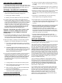
EF4001B AutoLite Pellet Stove Insert
Installation & Operating Instructions
Please read this entire manual before installation. Save these instructions.
PLEASE READ THIS ENTIRE MANUAL BEFORE INSTALLATION
AND USE OF THIS PELLET FUEL-BURNING ROOM HEATER.
FAILURE TO FOLLOW T HESE IN STRUCTION S COU LD RESULT IN
PROPERTY DAMAGE, BODILY INJURY OR EVEN DEATH.
GENERAL INFORMATION
Installation and repair should be done by a qualified
service person. The heater should be inspected before use
and at least annually by a professiona l service person. More
frequent cleaning m ay be re quired due to fuel quality,
excessive lint from carpetin g, bedding m ate rial, etc . It is
impera tive that control com partm ents , burn pot and c irculating air passageways of the heater be kept clean.
The EASYFIRE Pellet Insert has been designed and
approved for burning w oo d pellet fu el on ly. Bu rning solid
fuel in other forms is not permitted and will void all warranties.
This unit has been approved for use with a Ø 3" Type L
Pellet Vent System or Stainless Chimney Liner (Ø 4" on
runs 10 fee t and above).
SAFETY NOTICE
< CAUTION: HOT WHILE IN OPERATION. KEEP CHILDREN,
CLOTHING AND FURNITURE AWAY. CONTACT MAY
CAUSE SKIN BURNS.
< IF THIS HEATER IS NOT PROPERLY INSTALLED,
A HOUSE FIRE MAY RESULT.
< CONTACT LOCAL BU ILDING OFFICIALS ABOUT RESTRICTIONS AND INSTALLATION INSPECTION REQUIREMENTS IN YOUR AREA.
< FAILURE TO COMPLY WITH OWNERS' MANUAL INSTRUCTIONS WILL VOID YOUR WARRA NTY!
NOTE: This heater should not be installed in a
bedroom or bathroom.
NEVER use gasoline, gasoline-type lantern fuels,
kerosene, charcoal lighter fluid, or similar liquids to start or
"freshen up" a fire. Keep all such liquids well away from the
heater while it is in use.
Ashes must be disposed of in a metal container with a
tight fitting lid and placed on a noncombustible floor or
ground, we ll away from all fu els, pending fina l disposal.
NOTE : During the first few burns the high tem perature
paint and sealant used in manufacture will emit some odor
and smoke. Open doors and windows to the outside for
proper ventilation during the first burn cycle and curing of
the paint.
This heate r, when insta lled, m ust be electrically gro unded in
accordance with local codes or, in the absence of local
codes, with the National Electrical Code, ANSI/NFPA 702006.
INSTALLER: PLEASE LEAVE THIS MANUAL WITH THE OWNER!!
Sierra Products, Inc.
5061 Brooks St., Ste B
Montclair, CA 91763
(909) 399-3355
Listed by OMNI-Test
Laboratories, Inc.
Report No. 256-S-01-4
Provide ade qua te clearances around air openings into the
combustion chamber and adequate accessibility clearance for
servicing and prope r operation. Never obstruct the front
opening of the hea ter.
Use only listed Type "L" pellet vent or stainless liner and
com pon ents for installation. Failure to use listed com pon ents
will void your warranty. See pipe manufacturer instructions for
installation instructions.
The heater may be installed as a free-stan ding unit m oun ted on a noncombustible protective floor pad or he arth, o r it
may be m oun ted into an existing U. L. approved wood stove
chimney using a Hearth Extension (p/n 11099). Non-combustib le floor protection is required and must be used when
placing the heater on any com bustib le m ate rial.
OU TS IDE CO M BU ST ION AIR IS M AND ATO RY IN
MO BILE OR MO DULAR HOM E INSTALLATIONS. SEE
SECTION ON OUTSIDE AIR INSTALLATION.
C A U T IO N : D O N O T C O N NE C T
DISTRIBUTION DUCT O R SYSTEM .
The pellet heater m ust b e operated with a power source
and will not operate using natural draft. If there is a power
failure the heater will shut down. If the 12 volt back-up system
is installed, th e heater will auto m atic ally switc h to 12 volt
power. An optional backup battery is available for the unit
which lasts approximately 48 hrs on high and 72 hrs on low.
A bigger battery may be purch ased if desired for longer
durations.
TO
AN Y
AI R
INSTALLATION INSTRUCTIONS
Check with local building officials for specific code
requirements.
A listed , type "L" Pellet V ent Pip e or Stain less Liner is
MANDATORY on all installations.
The EasyFire Pellet Heater has been listed by OM NI-Test
Laboratories, Inc. to ASTM, U.L.,and EPA Standards.
WARNING: Installation of a Mobile Attachment Home
Kit P/N 1041 2 and ou tside c om bustion air is ma ndatory
in mobile or modular home installations although it may
also be used in all reside ntial application s.
CAUTION: Do not connect this unit to a chimney flue serving
another appliance.
An outs ide air inlet MU ST be provided for
com bustion and ven tilation air. The air inlet must
rem ain unrestricte d while unit is in use. O uts ide air
conne ction is located in the rear of the heater (Figure 1).
EF4100 Overall Dimensions
NOTE: Vent Pipes’ inner diameters may vary.
For Vent Pipes Ø3.00" or smaller, use SPI Exhaust Vent
Adapter p/n 11076.
This adapter is used on Selkirk Metalbestos™ and other
Ø2.950" I.D. Pellet Vent Pipes.
Use conduit pipe or metal flex pipe and/or fittings to make
the air intake hook-up.
Also, the struc tural inte grity of th e m obile hom e floor,
walls and ceiling/roof must be maintained.
1. Clean and inspect the fireplace and its chim ney for any
structural defect that may cause any future problems.
Secure gas piping that is installed with a cap and verify
there are no leaks. Seal ash dump or an y other acc ess to
the firebox area. Fix the damper in an open position or
remove it as required for vent pipe installation.
2. Verify the req uired hea rth an d side and clearanc es to
mantels (fig. 2 & 3).
Figure 2
2
NOT E: THE INSERT W EIGHT IS SUBST ANTIAULLY
FR ON T H EAVY A ND IF NOT FU LLY SU PPOR TE D IT
COULD FALL FORWARD.
Figure 5
4. Ins tall vent system into existing chimney by using 3" flex
from left side of he arth, pass ing da m per a nd c ontinu ing to
the top of the chimney. If the total vent length is longer than
10 Feet, install Ø4" vent from that point to top of chimney
(Figure 6).
Figure 3
3. If the hearth and fireplace floor are not at the same
elevation, leveling legs may be installed on the rear of the
unit (Figure 4) for distances of up to 1". For larger
distances shimm ing may be used using a non-com bustib le
m ate rial. A Hearth Base Support is available from your
dealer for installations where the hearth is below the
fireplace opening (Figure 5).
Figure 6
5. Pack fiberglass insulation around the vent pipe and
combustion air duct. Install a flashing cover over
chim ney. Se cure flas hing and seal as required. Ins tall
listed vent cap and secure.
6. Mea sure fireplace opening and adjust hopper top to the
required level allowing for installation clearance. This is
accomplished by removing the four #8 screws on the sides
and rear of un it and raising the top by 1" increm ents u ntil
desired height and reinstalling screws (Figure 4).
Figure 4
7. Slide insert into fireplace and center. Level as required,
then secure vent to outlet on left side of insert. Connect
combustion air duct and secure.
3
Note - For best insert operation the flexible vent
installation sho uld no t have any tight be nds. T ry to
achieve a smooth sweep to the vertical rise.
IMPORTANT - Any electrical work performed on the
EA SYFIRE H eater should be done by qualifie d personnel.
Remote Control Thermostat Installation:
SURROUND INSTALLATION
Th e re m ote therm ostat is designed to autom atic ally
regulate the room temperature from the control panel heat
setting to the “Off” setting base d upon roo m temp erature
and place m ent of the re m ote therm osta t. Rem em ber to
leave the control panel on the "Medium or High" position
when utilizing the wall thermostat feature.
The surround supplied with th e insert is adjus tab le in
height so as to allow for many installation perimeters.
1. After the insert is in position, install left and right surround
sides by attaching them to the two side brackets using the
four 1/4-2 0 bo lts provided. The retainer nuts on the
surround sid es m ay be installed at any vertical position to
accomm odate the installation.
The following is a step by step procedure for installing the
optional remote thermostat. Note connection terminals on
rear of un it (Figure 7).
2. Slide the surround top panel between the hopper top and
cover. Push the panel down until the screw holes align
with the side legs. Install the (4) #8 screws provided.
Install power cord into the receptacle on the right side of
the insert. Route cord behind surround leg and out to a
ground plus.
a. Unplug he ater from wall outlet and 12V DC power!
b. Mount millivolt style remote receiver box to rear of
stove using double-sided tape.
b. Rem ove factory jump wire and hook up thermostat
wires to terminals (Figure 7).
d. Re con nec t AC pow er an d follow instructions with
remote thermostat regarding set up.
AUTOLITE INSTALLATION INSTRUCTIONS
Th e Auto Lite Sys tem is fa cto ry ins talled with th e only
installation requ irem ents being the optiona l therm osta t.
IMPORTANT - Any electrical work performed on the
EA SYFIRE H eater should be done by qualifie d personnel.
Autolite Wiring Diagram
Figure 7 Connection Panel Lower Right Side
DOOR HANDLE ASSEMBLY
Wall Thermostat Installation:
The door handle and latch must be assembled and
adjusted prior to the operation of the stove.
The wa ll therm osta t is des igned to autom atically regulate
the ro om tem pera ture from the contro l pane l heat s etting to
the “Off” setting based upon room tem perature. Rem ember
to leave the control panel on the "Medium or High" position
when utilizing the wall thermostat feature.
1. Position hand le ass em bly through d oor a nd s ecu re with
collar by sliding over shaft and tightening with allen
wrench provided.
2. Position latch on end of shaft with flat facing allen screw.
Depending on gasket, shaft will protrude approx. 1/4"
through back of latch collar. Snug allen screw.
The following is a step by step procedure for installing the
optional wall therm ostat. Note conne ction terminals on left
side of unit at rear (Figure 7). Use 18/2 thermostat wire for
the installation.
a. Unplug he ater from wall outlet and 12V DC power!
b. Rem ove factory jump wire and hook up thermostat
wires to terminals (Figure 7).
c. Locate thermostat approximately 10 to 12 feet from
heater or in area that requires steady temperature.
d. Run thermostat wires from heater to thermostat along
wall or u nde r carpet etc. and ho ok wires to
thermostat terminals. On new construction you can,
of course, run wire in the walls before sheet rock or
paneling is done.
e. Reco nnect AC power.
f.
Figure 9
Door h andle a sse mbly
3. To adjust door, close a nd turn ha ndle so latc h co ntac ts
striker. Door gasket must contact firmly against front face
of unit. This can be che cked by closing against a piece of
paper. Firm ly tug on paper, if it m oves with solid
resistance the door is properly adjusted.
Make sure all wiring is completed before plugging the
EASYF IRE Heater b ack into the wall outlet.
4
1. A chimney connector shall no pass through and attic or
roof space , closet or similar concealed spa ce, or a floor,
or ceiling.
UNIT ELECTRIC CONNECTIONS
Route th e pow er supply cord from lower righ t side of un it
to a gro unded three prong 120V AC rec eptac le. C are should
be taken to mak e sure the fireplace and hearth does not
pinch or otherwise damage the cord.
2. W here a chimney passage through a wall, or partition of
com bustib le construction is desired, th e insta llation shall
conform the CAN/CSA-B365.
OPTIONAL 12V HOOK-UP & OPERATION
3. Maintain an effective vapour ba rrier at the location where
the chimney or other component penetrates to the
exterior of the structure by sealing with high temp erature
silicone.
1. The EASYFIRE 12V back up can be purchased as an
option and includes the following components:
a. Deep cycle sealed 12V battery.
4. Clearance to combustibles may only be reduced by
m eans approved by the re gulato ry au tho rity.
b. Battery connector cables for ho ok-up to the he ater.
2. In order to hook-up the battery and engage the 12V
backup system sim ply connect red cable to red terminal
on the heater (see Figure 6) and to positive connector on
battery [the terminal marked (+)] and connect the black
cable to the black terminal on the heater and to the
negative connector on the battery (the terminal marked
(-). If you hook up the cables backwards the red LED
light above the term inal rec epta cles will com e on . If
hooked up properly this LED will glow green.
5. Store pellet fuels in a dry area away from unit. Do not
store fuels within the space heater installation clearances
or within the space required for charging and ash
rem oval.
6. Adequ ate ventilation air is required to operate this heater.
During operation the heater draws air for combustion
which can be assisted by the installation of outside
combustion air inlets. However, certain weather
conditions such as icing or use of kitchen exhaust fans
m ay im pact a nd red uce the effe ctiveness of ve nts . It is
im portant to note th at room air s tarvation well negatively
impa ct the operation of the heater.
WARNING - MAKE SURE RED CABLE GOES TO RED
TERMINAL (POSITIVE CONNECTOR) AND BLACK
CABLE GOES TO BLACK TERM INAL (NEGATIVE
CO NN ECT OR ).
7. If pow er outag es with battery back up or room air
sta rva tion occurs during operation of h eater, sm ok e in
the house m ay result. This m ay trigger sm oke de tectors
if they are installed .
3. If you decide to purchase your own 12V back up system
we rec om m end a sealed gel cell batte ry. Failure to insta ll
the proper battery could cause physical harm to you and
your property and will also void the heate r warranty.
AUTOLITE OPERATION
4. W hen the battery is properly connected and the heater
plugged in, th e fo llowing will happen auto m atic ally:
Your EA SYF IRE Pellet S tove is equ ipped with th e Au tolite
Automatic ignition and operating system.
a. The heate r will autom atic ally switc h to 12V pow er if
there is a power failure, and switch back when power
is restored.
The AutoLite system is integrated into the stove to allow for
automatic start up using a heating element located in the
burn pot. This elem ent starts the initial fire required to burn
the wood pellets. The system operates on 120VAC power
supplied through a separate fuse and runs for five minutes
during the initial stove start up. After the five minute period
the AutoLite system is deactivated and the stove operates
based on the EasyFire digital control system requirements.
If the house AC powe r should quit, the Auto Lite system will
not be available however, with the optional battery attached
the stove can be manually lit and operate on battery power
for several days (depending on battery size, refer to the
EasyFire installation ma nual).
b. The battery will be trickle charged as long as the
heater is plugged into 110 AC wall outlet. Do not use
extension cords. The trickle charge will not recharge
a low or dead battery but it will keep a charged
battery at maximum performance.
5. If you choose to separate the battery from the heater by
lengthening the cables you must m ake sure that the
cable wire used will carry the current to the heater. For
example, if the distance is 10 to 20 feet then 12 gauge
wire must be used. Check with your local electrical
professional to mak e sure you have used the proper
gauge wire/cable.
Th e m ost effec tive insta llation of the Ea syFire Auto Lite
Stove is to connect the unit to a thermostat. This can be
acc om plishe d us ing a s tand ard w all therm osta t or a re m ote
control thermostat. A remote control thermostat can be
purchased from your local dealer and installed in a few
minutes. This will allow the stove to start and shut down
whe n there is a call for h eat.
a. Unplug he ater from wall outlet and 12V DC power!
b. Mount millivolt style remote receiver box to rear of
stove using double-sided tape.
If your house power is out the AutoLite system will not be
able to start the stove whe n the therm osta t calls for hea t.
However if the stove is operating when the power goes out
the stove will not shut down operating on the backup
battery. Your EasyFire will turn down to low when the
thermostat calls for shut down and then turn up to the
setting on the control panel when the thermostat calls for
heat. A true back up heat source!
b. Rem ove factory jump wire and hook up thermostat
wires to terminals (Figure 7).
d. Re con nec t AC pow er an d follow instructions with
remote thermostat regarding set up.
CANADIAN REQUIREMENTS
If this unit is being installed in Canada, the following
add itional req uirem ents m ust be m ean t:
5
attempt to operate heater if glass becomes dam aged in any
wa y!
GENERAL WARNINGS
The EASYFIRE Pellet Stove and Insert has been
designed and approved for burning w oo d p ellet fu el on ly.
Bu rning solid fu el in other form s is not perm itted and will
void all warranties.
NEVER use gasoline, gasoline-type lantern fuels,
kerosene, charcoal lighter fluid, or similar liquids to start or
"freshen up" a fire. Keep all such liquids well away from the
heater while it is in use.
Ashes must be disposed of in a metal container with a
tight fitting lid and placed on a noncombustible floor or
ground, we ll away from all fu els, pending fina l disposal.
This heate r, when insta lled, m ust be electrically gro unded in
accordance with local codes or, in the absence of local
codes, with the National Electrical Code, ANSI/NFPA 702006.
Provide adequate clearances around air openings into the
combu stion chamber and adequate accessibility clearance for
servicing and prope r operation. Never obstruct the front
opening of the hea ter.
The pellet heater must be operated with a power source
and will not operate using natural draft. If there is a power
failure the heater will shut down. If the 12 volt back-up system
is insta lled, the heate r will autom atic ally switc h to 12 volt
power. An optional back up battery is available fo r the unit
which lasts a pproxim ate ly 48 hrs on high and 72 hrs on low.
A bigger battery may be purchased if desired for longer
durations.
2. AutoLite Control Functions: Control functions on the
Easyfire are as follows: OFF, FAN, LOW , MEDIUM, HIGH,
CLEAN. Here is how each function works:
The EasyFire Pellet Heater has been listed by OMN I-Test
Laboratories, Inc. to ASTM, U.L.,and EPA Standards.
FUEL SELECTION
A.
Proper fue l selection is im portant for overall operation. Your
stove operates best with 1/4" diam eter wood pe llets that are
no longer than 3/4" long. The pellets should be specifically
manufactured for use pellet heaters. Use of fuel nonconforming fue l will cause the sto ve to operate erratica lly.
Ad ditionally, a low ash conte nt of be low 1% is required and
will reduce your cleaning and maintenance time. Sto re pe llets
in a clean dry area. Do not use pellets that have been damp
or have a moisture level above 5%.
The quality of pellet fuel va ries fro m bran d to bra nd. This will
affect the efficiency of your heater. W e sugge st that you try
several brand s u ntil you find one that gives you a clean efficient burn. Poor quality pellets will burn rich with black soot
and ash will accum ulate quickly. Qu ality pellets will burn clean
and ash build up will be m inim al.
W hen the Control Button is turned to FAN , a tim er is
activa ted and you will have abo ut ten (10) m inutes to
get the pellets lit and reach a minimum tem perature.
This function is used for match lighting when the AC
pow er is out.
Should the pellets not light in 10 minutes simply turn the
button to OFF and begin again. This will give you
another 10 minutes to get the pellets lit. The reason for
the tim er fun ctio n is so that the heate r will autom atic ally
shut down if the fire goes out. Pellets do not feed in the
FAN position.
B.
In the LOW position, the EASYFIRE will be feeding
approximately 1 to 1½ lbs. of pellets per hour and the
flam e will fluctuate betwe en 1 " and 6" in height.
AUTOLITE START-UP AND OPERATION
Refer to Installation and Op eration m anua l provided with
the unit for standard match lighting and 12V operations.
1. AutoLite Start-Up:
Prior to operating your AutoLite stove, make sure the
hop per is full of wo od p ellets and the interior com pon ents
have be en ins talled prope rly including ; burn screen & po t,
heat exch ange co vers, and ash drawer.
IMPORTANT: The Fire Pot must be seated flush and
must sit even in the pot tray. Air leaking around the Fire Pot
will create a poor burn (Figure 11). Light the pellets in Fire
Pot using any approve d pellet lighter.
Figure 11
Note: Caution must be taken when installing burn pot or
operating door not to damage ceramic glass. Do not
6
C.
WARNING: Risk of electrical shock, disconnect all AC/DC
power before servicing.
In the MEDIUM position the EASYFIRE will be
feeding approximately three (3) pounds of pellets per
hour and the flame will fluctuate between 3" and 8" of
fire.
D.
In the HIGH position the EASYFIRE will be feeding
approxim ate ly 4+ lbs. per ho ur and the fla m e will
fluctuate between 3" and a full flame. The fan speed
will increase accordingly as the heate r au tom atic ally
adjusts itself based on temperature inside the heater
(see G below).
E.
The CL EAN position is to be used only when the
heater is not burning and you wish to clean out the
accumulated ash in the front of the fire area. See
CLEAN OUT section of maintenance instructions.
F.
After the heater is running for several hours and you
wish to turn it off simply press the button to OFF. The
heater will continue running until it cools down
and then will automatically shut itself down.
G.
REMEMBER: Eac h fee d po sition will fluctu ate
because the m icroprocess or is auto m atic ally
adjus ting the fee d and air b ased on tem perature. T his
m eans the pellet feed ra te and flam e height w ill
change accordingly based on quality of pellet and
heat loss of dwelling.
ALWAYS TURN YOUR Heater OFF & LET IT COOL
BEFORE CLEANING.
Your EASYFIRE Pellet Heater requires routine
m aintenance for m axim um perform ance an d is ma ndatory
for the warranty to re m ain in effec t.
The following procedures should be studied carefully and
performed regularly as indicated:
1. Fly-ash: Some ash will accumulate in the heat
exchanger, Fire Pot and flue and should be cleaned out
on a regu lar basis for bes t efficien cy and sa fety. W hen
the heater is shut down and cold, you should:
a. Open door and remove Heat Exchanger Cover. To
rem ove, s im ply slide up and out from retaining angle
brac ket (Figure 12). Clea n on e side at a tim e. W ith
one slide cover rem oved, leave door open and turn
control button to the "CLEAN" position. Let heater
run until ash in Fire Pot area is vacuumed out by
heater fan. Turn off and replace co ver. Rem ove
remaining cover and repeat procedure for the other
side. T he vent pipe should be cleaned out after this
procedu re. Rem ove the clean-out port cover (Figu re
13) and vacuum as re quired.
3. Starting the S tove: Push a Heat Range button (Low or
Me dium is bes t for sta rt up) a nd turn the therm osta t up to
“Ca ll for heat”. The stove fan will beg in to op erate along with
the ignitor cycle. A fter ab out a m inute th e pellets w ill begin
to fall in the burn pot. After five m inutes there will be a fire in
the burn pot and the stove will begin to heat up. W hen the
stove reaches start up operating temperature it will then
sw itch to th e control panel setting and begin it’s autom atic
operation cycle.
b. Rem ove Fire Pot by lifting up and out, it may be
brushed out or vacuumed. Fire Pot should be
cleaned week ly and depending on pellet quality daily.
Make sure holes in pot are not clogged. The area
around an d below the pot shou ld be check ed every
five or six days depending on how many hours a day
you are burning your heater and the quality of the
pellets being burned. (After a few days you will be
able to determine the frequency needed for clean
out.)
Prior to stove operatin g on therm ostat, confirm proper operation by
servicing and adju sting the sto ve as ou tlined in the “Installation
Guide”. When servicing stove, operate with thermostat bypassed as
stove will reset to start up mode each time thermostat is activated.
The im portant th ing to rem em ber is that ex cess ive Flyash accumulation will affect the efficiency of the burn.
c. Scrape pellet feed chu te with putty knife to rem ove
hardened material on which sawdust can
accumulate.
Feed Trim Adjustment
d. The clean-out port cover should be removed and the
vent pipe checked every four to six weeks or
whenever you utilize the clean-out mode on the
control dial.
Underneath the control button you will find a small round
button that will turn forward and reverse. This button can
adjust the feed motor in the LOW operating position. By
turning the button clockwise you can increase the feed on
LOW and by turning it counterclockwise you can decrease
the feed in the LOW position. Factory setting is 1:00
o’clock.
e. Fly-ash can also accumulate in the vent pipe and
term ination cap . Inspect exha ust s ystem frequen tly to
maintain free flow of exhaust fumes and fly-ash. The
frequen cy of clean-out d epe nds entirely on the quality
of the pellets, so you will have to initially monitor the
buildup in the pellet vent pipe.
Once the stove is at operating temperature for one hour
set the stove on LO W. Adjust the trim button so that
averag e flam e is app rox. 1-2" abo ve the bu rn p ot. T his
will set the average feed rate (air/flue) for best
operation.
2. Hop per Clean Ou t: Vacuum the accumulated saw dust
in the hopper weekly. Keep free of debris and foreign
material. AN ACCUMULATION OF SAW DUST CAN
CA US E IR RE GU LAR P ELLET F EED. F or be st res ults
this should be done on a regular basis depending upon
how often the heater is used. If you burn the heate r all
the time you should do this every eight to ten days.
M ove this button carefully! It is designed to fine tune
your LOW setting in the event you ch ang e bra nds of pe llets
and/or live at a higher elevation. If this setting is to low the
sto ve m ay go out during LO W setting operatio ns. If this
sho uld ha ppe n increas e the trim by sm all am oun t.
3. Clea ning the E xha ust F an B lade & Hea t Exchan ger:
The exhaust blowe r should be checke d fo r ex cess ive Flyash buildup. Regular and routine maintenance utilizing
the CLEAN OUT feature will keep the exhaust blower
housing and fan blades clean. This cleaning can only be
don e wh en the he ater is NO T b urning. Fo r bes t resu lts
MAINTENANCE PROCEDURE
CAUTION: Moving parts may cause injury, DO NOT
operate with rear cover removed.
7
run the fan in the CLEAN OUT position with the door open
for approximately one minute or until ash is no longer being
picked up by the fan. Remem ber, you must always check
the clean out cap on the tee after utilizing the CLEAN OUT
feature.
Solution: W hen the pellets a re overfeeding, it us ually
m eans that the air flow has been red uced. Ch eck the F ire
Pot air intak e ho les to b e su re the y are clear. C hec k to
see if Fire Pot wa s pro perly se ated in pot tray. Che ck to
see if the manifold may have filled with Fly-ash. If you
use a low g rade pellet, an d clink ers (fused a sh a nd d irt)
form in the botto m of the Fire Pot, it will choke the air
intak e (you m ight co nsider ch ang ing the bran d of p ellets
to one that burns cleaner). You must let the fire go out
before rem oving and clean ing the Fire P ot.
4. Keeping the Glass Clean: If soot deposits acc um ulate
on the glass, clean with window glass cleaner and a
paper towel when the glass is cold.
5. Po lishin g th e G old and Nickel: All chrom e and gold
plating used on the EASYFIRE heater can be cleaned
with a soft cloth and non-abrasive cleane r.
Ne ver vacuum out the hea ter w hen th e he ater is in
operation! The hot ashes can lodge in your vacuum
cleaner and cause a fire!
6. Cleaning & Polishing Gold and Nickel Plated Parts:
Gold and N ick el is a soft m eta l and therefore a fragile
surface. Prior to the first burn it is important to use
W index or c om para ble product and a soft clean c loth to
wip e any m arks off all gold surfaces or the heat will
cause the m arks to rem ain in the surface perm anently.
Always clean the gold surface when the heater is COOL.
You must clean the manifold regularly in order to insure a
good air to fuel ratio, thus allowing the heater to "breathe"
properly. You must also check the vent pipe and tee to see
that they are not clogged and full of ash.
4. P roblem : Heater was burning well and then soot began
form ing on the glass door.
7. Doo r glass replace me nt: Should the door glass
become broken it may be replaced by scraping the sealer
from around the ou ter edge of the glass. Ca refully pry
glass from door frame then clean all sealer from fram e.
Obtain a replacement glass from your local dealer and
attach glass to door using High Temperature Silicon
Sealer (min. 400 / F). Apply sealer to all four corners of
the glass and set glass into frame. Apply sealer to mating
edge of glass and fram e. Allow two hours dry tim e before
installing doo r onto hea ter. Note: Replace with Corning
Pyro-Ceramic Glass only. Refer to parts list for
specifications.
Solution: Black soot forming on the glass door means
that the combustion is not right and the heater needs a
good clean out. Some brands of pellets burn much richer
than others and you might have to change brands of
pellets and/or have the air/fuel settings re-adjusted by
your dealer. It is normal to have the glass cloud up after
several hours of burning but it should wipe off with a
good window cleaner. If the glass turns black quick ly,
then the heate r nee ds a goo d clea n ou t.
5. P roblem : W e had a power failure and the heater
emitted smok e for about five minutes.
Troubleshooting Guide
Solution: If the heater emits smoke during a power
failure, and you have frequent power failures then we
suggest you purchase the battery back-up system. If the
vent pipe is installed according to these instructions the
smok e will syphon out of the pipe in most instances.
The following scenarios are provided in order to help you
locate a difficulty if the heater performs in a manner which
would seem to indicate a malfunction:
l. Problem: I loaded the heater for start-up, pressed the
button and pellets started but the fire didn't keep going.
6. P roblem : After several week s of outstanding performance, the heater suddenly stopped and the red light
under the control button came on. This light is the Hi
Te m p/Flue Indicator Light.
Solution: Rem ember that the timer on start up runs
about 10 minutes and if the heater has not heated up
enough to deactivate the timer you will have to start over
by pressing the button to off and then back to MEDIUM
or HIGH.
Solution: The Hi-Temp/Flue Indicator light indicates that
Fly-ash has built up in the exhaust s yste m and/o r there is
a restriction in the exhaust/flue system. Check the pipe
system for excessive ash and clogging, particularly the
vent cap. Remove the clean out cap on the tee and
make sure that ash has not blocked the exhaust air flow.
This automatic shut down in case of flue clogging is a
safety feature and if the shut down occurs it means you
have a problem and should consult a service technician
and/or clean your pipe and heater thoroughly. If you feel
the Fly-ash build up is excessive, we sugg est that you try
another brand. In moist climates the pellets and Fly-ash
can actually abso rb m oisture from the air and crea te
creosote and a severe clogging problem . Ke ep this in
mind when you store and handle your pellets. The heater
warranty does not cover the quality of the fuels used or
the way they may be han dled either before or after you've
purchased them.
EASYFIRE will automatically switch to 12 volt provided you have
the 12 volt battery option installed.
2. Problem: The heater was lit and burning properly, then
suddenly it stopped feeding pellets.
Solution: a) The thermostat setting is to low and the has
called for the sto ve to shut down . b) Ch eck p ellet su pply
in hopper. If empty, fill and follow start-up procedure as
outlined in the beginning of this m anual. c) Occasionally,
a foreign object, debris or an excessive amount of sawdust can enter the feed mechanism and jam the feed
chute. If this happens, you must empty the hopper and
check the feed chute to see what is causing the jam.
Rem ove any foreign material or object and re-start the
hea ter. CAUTION: Keep fingers and hands clear of feed
mechanism when heater is on.
7. P roblem : I turned off the switch and the heater kept
running.
Solution: This is normal. The exhaust blower will keep
running until it cools down and then it will auto m atic ally
turn off. This can vary by the temperature the exhaust
has reac hed and the temp erature of the cooling air.
3. Problem: The fire w as b urning we ll and the n it beg an to
overfeed pellets and started backing up into the pellet
feed chute, smothering the fire.
8
HI TEMP/FLUE AND TRIM INDICATORS:
W hen the H i-Tem p/Flue indicator light com es o n (red lite
beneath control button) it means that the flue is obstructed
or you have a re verse draft and gases cannot ex it properly.
Maintenance is required and a thorough cleaning and pipe
check m ust be performed.
TRIM button : Underneath the control button you will find a
sm all ro und butto n that w ill turn fo rward and reverse. This
button can control the fee d m oto r in th e LOW positio n only.
By turning the button clockwise you can increase the feed
on LOW and by turning it counterclockwise you can
decrease the feed in the LOW position.
M ove this button carefully! It is designed to fine tune
your LOW setting in the event you ch ang e bra nds of pe llets
and/or live at a higher elevation.
DC OPERATION - BUILDING A FIRE AND
START-UP
IMPO RTANT (Gold Units O nly): Gold is a soft metal and
therefore a fragile surface. Prior to th e first b urn it is important
to use W index™ or co m para ble produ ct with a soft clean cloth
to wipe any marks off all gold surfaces.
If not cleaned prior to first burn, the heat may cause the marks
to rem ain in the surface perm anently.
Always clean the gold surface when the heater is COOL.
Figure 12
1. Filling the Hopper and Start-Up:
CAUTION: Fuel hopper lid m ust be closed be fore
operating unit. Maintain hopper seal in good condition.
DO NOT OVERFILL HOPPER! The EAS YF IRE will hold
about 35 lbs. to 50 lbs. of pellets depending on hopp er
heigh t.
Allow pellets to burn for approxim ate ly 1 m inute, o r un til
pellet ignition has be en a chieved. Close door and turn the
control knob to the "FAN" position. Allow fire to burn for
several minutes. W hen the pellets are well lit, turn the
control knob to "L OW " for approximately 10 minutes then
turn up to "HI". W e recomm end that you run the heater on
“Medium” or "HI" for about 30 minutes in order to get the
heat exchanger hot before turning it to "LO W ". Yo u will
need to burn the heater for a few hours before deciding
which setting is best for your particular needs.
Open the top lid and fill the hopper with pellets (Figure 9).
The quality of pellet fuel varies from bra nd to brand. This
will affect the efficiency of your heater. W e suggest that you
try several brands until you find one that gives you a clean efficient burn. Poor quality pellets will burn rich with black soot
and ash will accu m ulate quickly. Quality pellets will burn clean
and ash build up will be m inim al.
Mak e sure hop per lid is fully closed. Ope n the front door.
Fill th e F ire Pot with pellet fuel.
IMPORTANT: The Fire Pot must be seated flush and
must sit even in the pot tray. Air leaking around the Fire Pot
will create a poor burn (Figure 10). Light the pellets in Fire
Pot using any approved lighter fluid.
Figure 13
9
Note: Caution must be taken when installing burn pot
or operating door not to damage ceramic glass. Do not
attempt to operate he ater if glas s be comes d am aged in
any w ay!
2. Control Functions: Control functions on the Eas yfire
are as follows: OFF, FAN, LOW , MEDIUM, HIGH, CLEAN.
Here is how each function works:
A.
W hen the Control is set to FAN , a timer is activated
and you will have about ten (10) minutes to get the
pellets lit and rea ch a m inim um tem pera ture.
ALWAYS TURN YOUR Heater OFF & LET IT COOL
BEFORE CLEANING.
Your EASYFIRE Pellet Heater requires routine
m aintenance for m axim um perform ance an d is ma ndatory
for the warranty to re m ain in effec t.
The following procedures should be studied carefully and
performed regularly as indicated:
1. Fly-ash: Some ash will accumulate in the heat
exchanger, Fire Pot and flue and should be cleaned out
on a regu lar basis for bes t efficien cy and sa fety. W hen
the heater is shut down and cold, you should:
Should the pellets not light in the 10 m inutes simp ly turn
the knob to OFF and begin again. This will give you
another 10 minutes to get the pellets lit. The reason for
the tim er fun ctio n is so that the heate r will autom atic ally
shut down if the fire goes out. Pellets do not feed in the
FAN position.
B.
In the LOW position, the EASYFIRE will be feeding
approximately 1 to 1½ lbs. of pellets per hour and the
flam e will fluctuate betwe en 1 " and 6" in height.
C.
In the MEDIUM position the EASYFIRE will be
feeding approximately three (3) pounds of pellets per
hour and the flame will fluctuate between 3" and 8" of
fire.
D.
In the HIGH position the EASYFIRE will be feeding
approxim ate ly 4 lbs. p er hour and the fla m e will
fluctuate between 3" and a full flame. The fan speed
will increase accordingly as the heate r au tom atic ally
adjusts itself based on temperature inside the heater
(see G below).
E.
The CL EAN position is to be used only when the
heater is not burning and you wish to clean out the
accumulated ash in the front of the fire area. See
CLEAN OUT section of maintenance instructions.
F.
After the heater is running for several hours and you
wish to turn it off simply turn the knob to OFF. The
heater will continue running until it cools down
and then will automatically shut itself down.
G.
REMEMBER: Eac h fee d po sition will fluctu ate
because the m icroprocess or is auto m atic ally
adjus ting the fee d and air b ased on tem perature. T his
m eans the pellet feed ra te and flam e height w ill
change accordingly based on quality of pellet and
heat loss of dwelling.
a. Open door and remove Heat Exchanger Cover. To
rem ove, s im ply slide up and out from retaining angle
brac ket (Figure 12). Clea n on e side at a tim e. W ith
one slide cover rem oved, leave door open and turn
control knob to the "CLEAN" position. Let heater run
Figure 14
until ash in Fire Pot area is vacuumed out by heater
fan. Turn off and replace cover. Rem ove remaining
cover and repeat procedure for the other side. The
vent pipe should be cleaned out after this procedure.
Rem ove the clean-out port cover (Figure 13) and
vacuum as re quired.
b. Rem ove Fire Pot by lifting up and out, it may be
brushed out or vacuumed. Fire Pot should be
cleaned daily. Make sure holes in pot are not
clogged. The are a around and below the pot sh ould
be checked every five or six days depending on how
many hours a day you are burning your heater and
the quality of the pellets being burned. (After a few
days you will be able to determine the frequency
nee ded for clean out.)
MAINTENANCE PROCEDURE
CAUTION: Moving parts may cause injury, DO NOT
operate with rear cover removed.
The im portant th ing to rem em ber is that ex cess ive Flyash accumulation will affect the efficiency of the burn.
WARNING: Risk of electrical shock, disconnect all power
before servicing.
c. Scrape pellet feed chu te with putty knife to rem ove
hardened material on which sawdust can
accumulate.
10
3. Clea ning the E xha ust F an B lade & Hea t Exchan ger:
The exhaust blowe r should be checke d fo r ex cess ive Flyash buildup. Regular and routine maintenance utilizing
the CLEAN OUT feature will keep the exhaust blower
housing and fan blades clean. This cleaning can only be
don e wh en the he ater is NO T b urning. Fo r bes t resu lts
run the fan in the CLEAN OUT position with the door
open for approximately one minute or until ash is no
longer being picked up by the fan. Rem ember, you must
always check the clean out tee after utilizing the CLEAN
OUT feature (Figure 13).
4. Keeping the Glass Clean: If soot deposits acc um ulate
on the glass, clean with window glass cleaner and a
paper towel when the glass is cold.
5. Polishing the Gold and Chrom e: All chrom e and gold
plating used on the EASYFIRE heater can be cleaned
with a soft cloth and non-abrasive cleane r.
Figure 15
Front ash access panel
d. The clean-out port cover should be removed and the
vent pipe checked every four to six weeks or
whenever you utilize the clean-out mode on the
control dial.
e. Fly-ash can also accumulate in the vent pipe and
term ination cap . Inspect exha ust s ystem frequen tly to
maintain free flow of exhaust fumes and fly-ash. The
frequen cy of clean-out d epe nds entirely on the quality
of the pellets, so you will have to initially monitor the
buildup in the pellet vent pipe.
2. Hop per Clean Ou t: Vacuum the accumulated saw dust
in the hopper weekly. Keep free of debris and foreign
material. AN ACCUMULATION OF SAW DUST CAN
CA US E IR RE GU LAR P ELLET F EED. F or be st res ults
this should be done on a regular basis depending upon
how often the heater is used. If you burn the heate r all
the time you should do this every eight to ten days.
6. Cleaning & Polishing Gold Plated Parts: Gold is a soft
metal and therefore a fragile surface. Prior to the first
burn it is important to use Windex or comparable product
and a soft clean cloth to w ipe any m arks off all gold
surfaces or the heat will cause the marks to remain in the
surface permanently. Always clean the gold surface
when the heater is COOL.
7. Doo r glass replace me nt: Should the door glass
become broken it may be replaced by scraping the sealer
from around the ou ter edge of the glass. Ca refully pry
glass from door frame then clean all sealer from fram e.
Obtain a replacement glass from your local dealer and
attach glass to door using High Temperature Silicon
Sealer (min. 400 / F). Apply sealer to all four corners of
the glass and set glass into frame. Apply sealer to mating
edge of glass and fram e. Allow two hours dry tim e before
installing doo r onto hea ter. Note: Replace with Corning
Pyro-Ceramic Glass only. Refer to parts list for
specifications.
8. Plenu m c lean ou t & draft adju stme nt: Access to clean
under the burn pot is through the plenum clean out plates
on right or left side low front (Figure 16). Remove the
fastener and plate and vacuum out ash accumulations.
Ad ditionally, the dra ft plate is accessible through this
opening and maybe turned with a long standard screw
driver clockw ise to re duc e the draft through the bu rn po t.
This adjustment is made generally only during
installation .
Troubleshooting Guide
The following scenarios are provided in order to help you
locate a difficulty if the heater performs in a manner which
would seem to indicate a malfunction:
l. P roblem : I loaded the h eater for start-up, lit the fire
starter and pellets but the fire didn't keep going.
Solution: Check pow er co rd to s ee that it is plugg ed in.
Rem ember that the timer on start up runs about 10
m inutes and if the he ater h as n ot heated up enou gh to
Figure 16 Plenum Clean Out & Draft Adjustment
11
deactivate the timer you will have to start over by turning the
knob to off and then back to FAN or LOW.
The EASYFIRE will automatically switch to 12 volt backup
provided you have the 12 volt option installed.
2. Problem: The heater was lit and burning properly, then
suddenly it stopped feeding pellets.
vent pipe is installed according to these instructions the
smok e will syphon out of the pipe in most instances.
6. P roblem : After several week s of outstanding performance, the heater suddenly stopped and the red light
under the control knob came on. This light is the Hi
Te m p/Flue Indicator Light.
Solution: The Hi-Temp/Flue Indicator light indicates that
Fly-ash has built up in the exhaust s yste m and/o r there is
a restriction in the exhaust/flue system. Check the pipe
system for excessive ash and clogging, particularly the
vent cap. Remove the clean out cap on the tee and
make sure that ash has not blocked the exhaust air flow.
This automatic shut down in case of flue clogging is a
safety feature and if the shut down occurs it means you
have a problem and should consult a service technician
and/or clean your pipe and heater thoroughly. If you feel
the Fly-ash build up is excessive, we sugg est that you try
another brand. In moist climates the pellets and Fly-ash
can actually abso rb m oisture from the air and crea te
creosote and a severe clogging problem . Ke ep this in
mind when you store and handle your pellets. The heater
warranty does not cover the quality of the fuels used or
the way they may be han dled either before or after you've
purchased them.
Solution: a) C heck pellet supply in hopper. If em pty, fill
and follow start-up procedure as outlined in the beginning
of this m anual. b) O cc asionally, a foreign obje ct, debris
or an excessive amount of sawdust can enter the feed
mechanism and jam the feed chute. If this happens, you
must em pty the hopper and check the feed chute to see
what is causing the jam. Rem ove any foreign material or
obje ct and re-start the he ater. CAUTION: Keep fingers
and hands clear of feed mechanism when heater is on.
3. Problem: The fire w as b urning we ll and the n it beg an to
overfeed pellets and started backing up into the pellet
feed chute, smothering the fire.
Solution: W hen the pellets a re overfeeding, it us ually
m eans that the air flow has been red uced. Ch eck the F ire
Pot air intak e ho les to b e su re the y are clear. C hec k to
see if Fire Pot wa s pro perly se ated in pot tray. Che ck to
see if the manifold may have filled with Fly-ash. If you
use a low g rade pellet, an d clink ers (fused a sh a nd d irt)
form in the botto m of the Fire Pot, it will choke the air
intak e (you m ight co nsider ch ang ing the bran d of p ellets
to one that burns cleaner). You must let the fire go out
before rem oving and clean ing the Fire P ot.
Ne ver vacuum out the hea ter w hen th e he ater is in
operation! The hot ashes can lodge in your vacuum
cleaner and cause a fire!
You must clean the manifold regularly in order to insure a
good air to fuel ratio, thus allowing the heater to "breathe"
properly. You must also check the vent pipe and tee to see
that they are not clogged and full of ash.
4. Problem: Heater was burning well and then soot began
form ing on the glass door.
Solution: Black soot forming on the glass door means
that the combustion is not right and the heater needs a
good clean out. Some brands of pellets burn much richer
than others and you might have to change brands of
pellets and/or have the air/fuel settings re-adjusted by
your dealer. It is normal to have the glass cloud up after
several hours of burning but it should wipe off with a
good window cleaner. If the glass turns black quick ly,
then the heate r nee ds a goo d clea n ou t.
7. P roblem : I turned off the switch and the heater kept
running.
Solution: This is normal. The exhaust blower will keep
running until it cools down and then it will auto m atic ally
turn off. This can vary by the temperature the exhaust
has reac hed and the temp erature of the cooling air.
HI TEMP/FLUE AND TRIM INDICATORS:
W hen the H i-Tem p/Flue indicator light com es o n (red lite
beneath control knob) it means that the flue is obstructed or
you have a re verse draft and gases cannot ex it properly.
Maintenance is required and a thorough cleaning and pipe
check m ust be performed.
TRIM button : Underneath the control knob you will find a
sm all ro und butto n that w ill turn fo rward and reverse. This
button can control the fee d m oto r in th e LOW positio n only.
By turning the button clockwise you can increase the feed
on LOW and by turning it counterclockwise you can
decrease the feed in the LOW position.
M ove this button carefully! It is designed to fine tune
your LOW setting in the event you ch ang e bra nds of pe llets
and/or live at a higher elevation.
5. Problem: W e had a power failure and the heater
emitted smok e for about five minutes.
Solution: If the heater emits smoke during a power
failure, and you have frequent power failures then we
suggest you purchase the battery back-up system. If the
12
ITEM No.
PART NUMBER
DESCRIPTION
1
110429
DOOR FRONT GLASS (Ceramic glass 11"x11 3/4"x5mm)
2
100119
GLASS FIBER GASKET
3
100125
DOOR FIBER ROPE GASKET
4
300536
FEED AUGER SYSTEM V3
5
300106
COMBUSTION BLOWER ASSEMBLY
6
120114
CONTROL BOARD V2.1
6A
110080
MAIN FUSE - 1 AMP
6B
110510
AUTOLITE FUSE - 5 AMP
7
200549
HEAT EXCHANGE COVER
8
110456
ASH DRAWER FIBER ROPE GASKET
9
110451
ASH DRAWER KNOB
10
120117
IGNITOR-200W
11
300512
BURN POT AL V2
12
120120
IGNITOR RELAY
13
120118
PUSH BUTTON SWITCH V2.1
14
110058
HANDLE ASSEMBLY
15
10407
SURROUND ASSEMBLY
5061 Brooks St. Montclair, CA 91763
Phone 1-909-399-3355 Fax 1-909-399-3357
www.empireproductsinc.com
P/N 140706r3 03/08


![FV2330 - FAST CORPORATION[株式会社ファースト]](http://vs1.manualzilla.com/store/data/006579592_2-1e3e8f11fc57171053373d9908d22bc8-150x150.png)