1
DAT’AIR
Manuale
Emissione
Sostituisce
Manual
Issue
Replaces
201370A12
08.99
05.97
Manuale di uso,
installazione
e manutenzione
Installation,
use and
maintenance
manual
1370
Condizionatori d’aria
ad espansione diretta
ed ad acqua
refrigerata
Aria/aria, acqua/aria
Compressori scroll e
ventilatori centrifughi
Air conditioning
direct expansion and
chilled water
Air/air, water/air
Scroll compressors and
centrifugal fan
DATI TECNICI
Refrigerante R22 - R407c
TECHNICAL DATA
Refrigerant R22 - R407c
MODELLO
MODEL
MINIDAT
50
80
100
140
180
MODULAR
230
260
350
440
520
Resa frigorifera
*EDA
kW
6,0
8,7
10,5
13,1
16,3
19,1
24,5
32,8
42,1
49,0
Cooling capacity
*EDW
kW
6,3
9,4
11,1
13,9
17,1
20,3
26,5
35,1
44,8
52,3
*EDR
kW
6,1
9,0
10,7
13,4
16,6
19,6
25,3
33,7
43,1
50,3
Resa frigorifera sensibile
*EDA
kW
5,4
7,4
10,2
12,8
15,5
17,4
24,5
30,5
38,3
42,6
Sensible cooling capacity
*EDW
kW
5,4
7,6
10,4
13,2
15,9
17,9
25,7
31,6
39,4
43,9
*EDR
kW
5,5
7,7
10,4
13,1
15,8
17,8
25,3
31,3
39,2
43,8
Potenza assorbita in raffreddamento
*EDA
kW
1,5
2,2
2,4
3,2
3,9
4,6
5,7
7,7
9,6
12,7
Absorbed power cooling
*EDW
kW
1,3
1,9
2,0
2,7
3,4
3,9
4,7
6,4
7,9
10,9
*EDR
kW
1,4
2,1
2,3
3,1
3,8
4,4
5,3
7,2
8,9
12,0
Compressore tipo
scroll
scroll
Compressor type
scroll
scroll
Quantità
Quantity
n°
1
1
1
1
1
1
1
1
1
1
l
1,00
1,10
1,10
1,85
1,55
1,65
4,00
4,00
4,00
4,00
1 x 3,0
Carica olio
Oil charge
Scambiatore utenza tipo
batt. alettata
batt. alettata
finned coil
finned coil
User exchanger type
Pot. nominale ventilatori
Fan motor nominal power
n° x kW
1 x 0,25
1 x 0,25
1 x 1,1
1 x 1,1
1 x 1,1
1 x 1,1
1 x 1,1
1 x 1,5
1 x 2,2
Portata aria lato utenze
m3/s
0,444
0,556
1,111
1,250
1,389
1,389
2,083
2,500
2,777
3,055
User air flow
m3/h
1600
2000
4000
4500
5000
5000
7500
9000
10000
11000
Pa
50
50
25
25
25
25
25
25
25
25
Pressione statica disp. lato utenza
User available static pressure
Scambiatore sorgente tipo
solo per *EDW, *EDR
piastre
piastre
Source exchanger type
only for *EDW, *EDR
plate
plate
Max. pressione di esercizio
Max. operating pressure
bar
30
30
30
30
30
30
30
30
30
30
bar
10
10
10
10
10
10
10
10
10
10
Max. press. eserc. (lato acqua)
Max operat. press. (water side)
RESE RIFERITE A: *EDA temperatura aria esterna 32°C;*EDW temperatura acqua utenza ing. 15°C; *EDR ing./usc. 35-40°C; temperatura aria ingresso evaporatore 24°C 50% UR.
CAPACITY REFERRED TO: *EDA ambient air temperature 32°C; *EDW user water temperature in 15°C; *EDR in/out 35-40°C; evaporator air inlet temperature 24°C 50% UR.
DATI TECNICI
Refrigerante R22 - R407c
TECHNICAL DATA
Refrigerant R22 - R407c
MODELLO
MODEL
110
CONSOLE
150
170
280
360
460
BIGDAT
600
760
860
960
Resa frigorifera
*EDA
kW
10,9
14,3
16,8
26,2
32,6
38,2
49,2
65,6
82,8
98,0
Cooling capacity
*EDW
kW
11,7
14,9
17,7
27,8
34,2
40,6
52,9
70,0
89,3
104,0
*EDR
kW
11,2
14,5
17,1
26,8
33,2
39,2
50,6
67,3
85,3
100,3
Resa frigorifera sensibile
*EDA
kW
10,4
14,3
16,1
25,6
31,0
34,8
49,2
60,4
75,4
85,3
Sensible cooling capacity
*EDW
kW
10,8
14,9
16,5
26,4
31,8
35,8
50,8
62,3
77,7
87,4
*EDR
kW
10,6
14,5
16,4
26,2
31,6
35,6
50,6
61,9
77,6
87,3
Potenza assorbita in raffreddamento
*EDA
kW
2,4
3,2
3,9
6,4
7,8
9,2
11,4
14,4
19,2
25,5
Absorbed power cooling
*EDW
kW
2,0
2,8
3,4
5,4
6,8
7,8
9,4
12,7
15,9
21,9
*EDR
kW
2,3
3,1
3,8
6,2
7,6
8,8
10,7
13,8
18,0
24,2
2
2
2
2
2 x 4,00
2 x 4,00
2 x 4,00
2 x 4,00
2 x 3,0
Compressore tipo
scroll
scroll
Compressor type
scroll
scroll
Quantità
Quantity
n°
1
l
1,10
1
1
2
2
2
1,85
1,55
2 x 1,85
2 x 1,55
2 x 1,65
Carica olio
Oil charge
Scambiatore utenza tipo
User exchanger type
batt. alettata
batt. alettata
finned coil
finned coil
Pot. nominale ventilatori
Fan motor nominal power
n° x kW
2 x 0,25
3 x 0,25
3 x 0,25
2 x 1,1
2 x 1,1
2 x 1,1
2 x 1,1
2 x 1,5
2 x 2,2
Portata aria lato utenze
m3/s
0,889
1,361
1,361
2,500
2,778
2,778
4,167
5,000
5,556
6,111
User air flow
m3/h
3200
4900
4900
9000
10000
10000
15000
18000
20000
22000
Pa
50
50
50
25
25
25
25
25
25
25
Pressione statica disp. lato utenza
User available static pressure
Scambiatore sorgente tipo
solo per *EDW, *EDR
piastre
piastre
piastre
Source exchanger type
only for *EDW, *EDR
plate
plate
plate
Max. pressione di esercizio
Max. operating pressure
bar
30
30
30
30
30
30
30
30
30
30
bar
10
10
10
10
10
10
10
10
10
10
Max. press. eserc. (lato acqua)
Max operat. press. (water side)
RESE RIFERITE A: *EDA temperatura aria esterna 32°C;*EDW temperatura acqua utenza ing. 15°C; *EDR ing./usc. 35-40°C; temperatura aria ingresso evaporatore 24°C 50% UR.
CAPACITY REFERRED TO: *EDA ambient air temperature 32°C; *EDW user water temperature in 15°C; *EDR in/out 35-40°C; evaporator air inlet temperature 24°C 50% UR.
DATI TECNICI
TECHNICAL DATA
MODELLO
MODEL
OFC
UFC
MINIDAT
50
80
CONSOLE
110
170
200
MODULAR
300
360
100
140
500
750
1000
kW
6,3
8,8
12,0
19,5
11,6
17,2
20,7
29,8
38,1
52,6
82,7
101,4
kW
5,5
7,6
10,8
17,5
10,9
15,7
18,1
25,0
32,6
45,4
71,7
83,6
3/4 "
3/4 "
batt. alettata
1"
1"
batt. alettata
1"
1"
1"
1 1/4 "
1 1/2 "
2"
finned coil
finned coil
Resa frigorifera
Cooling capacity
Resa frigorifera sensibile
Sensible cooling capacity
Connessioni ing./usc. acqua
Connections water inlet/outlet
Ø BSP F
Scambiatore utenza tipo
User exchanger type
1 1/4 " 1 1/4 "
batt. alettata
finned coil
Pot. nominale ventilatori
Fan motor nominal power
Portata aria lato utenze
User air flow
n° x kW
m3/s
m3/h
1 x 0,25 1 x 0,25 2 x 0,25 3 x 0,25 1 x 1,1
0,444
0,556
0,889
1,361
1,111
1600
2000
3200
4900
4000
1 x 1,1
1,250
4500
1 x 1,1
1,389
5000
1 x 1,1
1,806
6500
1 x 1,1
2,083
7500
1 X 2,2
3,056
11000
2 x 1,5
5,000
18000
2 x 2,2
5,556
20000
25
25
25
25
25
25
25
Pressione statica disp. lato utenza
User available static pressure
Pa
50
50
50
50
RESE RIFERITE A:acqua di alimentazione ing./usc. 7-12°C; temperatura aria ingresso 24°C 50% UR.
CAPACITY REFERRED TO: chilled water in/out 7-12°C; air inlet temperature 24°C 50% UR.
25
DATI ELETTRICI
Refrigerante R22 - R407c
ELECTRICAL DATA
Refrigerant R22 - R407c
MODELLO
MINIDAT
50
80
MODEL
100
140
180
MODULAR
230
260
350
440
520
Massima potenza assorbita *
Maximum absorbed power *
Kw
2,3
3,4
4,7
5,3
6,4
7,2
8,8
12,2
15,4
18,5
A
15,3
21,9
12,5
14,1
16,1
19,4
21,4
28,6
35,0
42,0
A
47,3
78,3
46,8
54,3
63,3
73,8
97,3
130,9
163,8
195,4
Kw
3,0
3,0
5,0
5,0
5,0
5,0
10,0
10,0
10,0
10,0
A
13,0
13,0
7,6
7,6
7,6
7,6
15,2
15,2
15,2
15,2
Kw
1,5
1,5
3,6
3,6
3,6
3,6
3,6
3,6
3,6
3,6
A
6,6
6,6
5,5
5,5
5,5
5,5
5,5
5,5
5,5
5,5
Kw
1,5
2,2
2,4
3,2
3,9
4,6
5,7
7,7
9,6
12,7
Massima corrente assorbita **
Maximum absorbed current **
Corrente massima allo spunto
Maximum starting current
Potenza resistenze
Electric heater power
Corrente assorbita resistenze
Absorbed electric heater current
Potenza umidificatore
Humidifier power
Corrente assorbita umidificatore
Absorbed humidifier current
Potenza nominale compressore
Compr.nominal absorbed power
Alimentazione elettrica
Power supply
V/~/Hz
230/1~/50
400/3~/50
V/~/Hz
230-24/1~/50
230-24/1~/50
Alimentazione ausiliari
Control power supply
POTENZA NOMINALE COMPRESSORE RIFERITA A: temperatura aria esterna 32°C; temperatura aria ingresso evaporatore 24°C 50% UR.
COMPRESSOR NOMINAL ABSORBED POWER REFERRED TO: ambient air temperature 32°C; evaporator air inlet temperature 24°C 50% UR.
* Riferita alle massime condizioni ammesse (versioni CO)
* Referred to maximum declared operating conditions (CO versions)
** Riferita al valore di intervento delle protezioni interne del compressore (versioni CO)
** Referred to cut-off compressor internal protection (CO versions)
DATI ELETTRICI
Refrigerante R22 - R407c
ELECTRICAL DATA
Refrigerant R22 - R407c
MODELLO
110
CONSOLE
150
170
280
360
460
BIGDAT
600
760
860
960
Kw
4,1
5,0
6,1
10,6
12,8
14,4
17,6
24,4
30,8
37,0
A
13,8
17,7
19,7
28,2
32,2
38,8
42,2
57,2
69,8
84,0
A
48,1
57,9
66,4
68,4
79,4
93,8
118,7
159,4
198,7
237,4
Kw
5,0
5,0
5,0
10,0
10,0
10,0
15,0
15,0
15,0
15,0
A
7,6
7,6
7,6
15,2
15,2
15,2
21,2
21,2
21,2
21,2
Kw
3,6
3,6
3,6
3,6
3,6
3,6
5,8
5,8
5,8
5,8
A
5,5
5,5
5,5
5,5
5,5
5,5
8,8
8,8
8,8
8,8
Kw
2,4
3,2
3,9
6,4
7,8
9,2
11,4
14,4
19,2
25,5
MODEL
Massima potenza assorbita *
Maximum absorbed power *
Massima corrente assorbita **
Maximum absorbed current **
Corrente massima allo spunto
Maximum starting current
Potenza resistenze
Electric heater power
Corrente assorbita resistenze
Absorbed electric heater current
Potenza umidificatore
Humidifier power
Corrente assorbita umidificatore
Absorbed humidifier current
Potenza nominale compressore
Compr.nominal absorbed power
Alimentazione elettrica
Power supply
V/~/Hz
400/3N~/50
400/3~/50
V/~/Hz
230-24/1~/50
230-24/1~/50
Alimentazione ausiliari
Control power supply
POTENZA NOMINALE COMPRESSORE RIFERITA A: temperatura aria esterna 32°C; temperatura aria ingresso evaporatore 24°C 50% UR.
COMPRESSOR NOMINAL ABSORBED POWER REFERRED TO: ambient air temperature 32°C; evaporator air inlet temperature 24°C 50% UR.
* Riferita alle massime condizioni ammesse (versioni CO)
* Referred to maximum declared operating conditions (CO versions)
** Riferita al valore di intervento delle protezioni interne del compressore (versioni CO)
** Referred to cut-off compressor internal protection (CO versions)
DATI ELETTRICI
ELECTRICAL DATA
MODELLO
MODEL
OFC
UFC
MINIDAT
50
80
CONSOLE
110
170
Kw
0,25
0,25
0,50
A
2,3
2,3
A
-
Kw
MODULAR
300
360
100
140
200
500
750
1000
0,75
1,1
1,1
1,1
1,1
1,1
2,2
3,0
4,4
4,6
6,9
3,3
3,3
3,3
3,3
3,3
5,4
7,8
10,8
-
-
-
2.5/4
2.5/4
2.5/4
2.5/4
2.5/4
4/6.3
3
3
5
5
5
5
5
10
10
10
15
15
A
13,0
13,0
7,6
7,6
7,6
7,6
7,6
15,2
15,2
15,2
21,2
21,2
Kw
1,5
1,5
3,6
3,6
3,6
3,6
3,6
3,6
3,6
3,6
5,8
5,8
A
6,6
6,6
5,5
5,5
5,5
5,5
5,5
5,5
5,5
5,5
8,8
8,8
Massima potenza assorbita *
Maximum absorbed power *
Massima corrente assorbita *
Maximum absorbed current *
Salvamotore ventilatore (QMV)
User fan protection (QMV)
2 x 2.5/4 2 x 4/6.3
Potenza resistenze
Electric heater power
Corrente assorbita resistenze
Absorbed electric heater current
Potenza umidificatore
Humidifier power
Corrente assorbita umidificatore
Absorbed humidifier current
Alimentazione elettrica
Power supply
V/~/Hz
230/1~/50
400/3N~/50
400/3~/50
V/~/Hz
230-24/1~/50
230-24/1~/50
230-24/1~/50
Alimentazione ausiliari
Control power supply
* Riferita alle versioni CO.
* Referred to CO versions.
INDICE
Pag
INDEX
Pag
CONTENTS
ARGOMENTO
LA SERIE
1
THE SERIES
1
CAMPO DI APPLICAZIONE
2
FIELD OF APPLICATION
2
GENERALITA'
3
1. GENERAL
3
2. ISPEZIONE, TRASPORTO, POSIZIONAMENTO
3
2. INSPECTION,TRANSPORTATION,
POSITIONING
3
2.1 Ispezione
3
2.1 Inspection
3
2.2 Sollevamento e trasporto
3
2.2 Lifting and transporting
3
2.3 Disimballaggio
4
2.3 Unpacking
4
2.4 Posizionamento
4
2.4 Positioning
4
2.5 Fondazioni
5
2.5 Base
5
2.6 Distribuzione dell'aria
6
2.6 Air distribution
6
2.7 Caratteristiche dell'ambiente
6
2.7 Room characteristics
6
2.8 Presa aria esterna (optional)
7
2.8 Fresh air intake (optional)
7
2.9 Estrazione e pulizia dei filtri
7
2.9 Filter extraction and cleaning
7
3. INSTALLAZIONE E COLLEGAMENTI
8
3. INSTALLATION AND CONNECTIONS
8
3.1 Spazi di installazione
8
3.1 Installation clearance
8
1.
3.2 Collegamenti a componenti remoti
(*EDA)
3.2.1 Stesura delle tubazioni
3.2.2 Allacciamento delle tubazioni
3.2.3 Valvola fusibile di sicurezza
3.3 Collegamenti idraulici
3.3.1 Al condensatore ad acqua
(*EDW)
3.3.2 Al condensatore ad acqua in
un circuito chiuso (*EDR)
3.3.3 Alla batteria di
raffreddamento (*FC)
3.3.4 Alla batteria di riscaldamento
(optional)
3.3.5 Scarico della condensa
3.3.6 Collegamento allo
umidificatore (versioni HH)
3.3.7 Raccomandazioni generali per
i collegamenti idraulici
8
10
10
11
11
11
11
12
12
16
16
17
3.2 Connection to remote components
(*EDA)
3.2.1 Pipelines installation
3.2.2 Refrigerant pipelines
connections
3.2.3 Fuseplug
3.3 Piping connections
3.3.1 To the Water Condenser
(*EDW)
3.3.2 To the Water Condenser on a
Closed Circuit (*EDR)
3.3.3 To the Cooling Battery (*FC)
3.3.4 To the heating coil (optional)
3.3.5 Condensation drainage
3.3.6 Connection to humidifier (HH
versions)
3.3.7 General advice on water pipe
connections
8
10
10
11
11
11
11
12
12
16
16
17
3.4 Collegamenti elettrici
3.4.1 Generalità
3.4.2 Consensi esterni
18
18
19
3.4 Electrical power and earthing
3.4.1 General
3.4.2 External consents
18
18
19
3.5 Controllo a microprocessore
3.5.1 Interfaccia seriale RS422
(optional)
19
19
3.5 Microprocessor control
3.5.1 RS 422 serial interface
(optional)
19
19
4. LIMITI DI FUNZIONAMENTO
20
4. OPERATING LIMITS
20
4.1 Temperatura acqua di
condensazione
20
4.2 Temperatura aria esterna (*EDA)
20
4.2 Outdoor air temperature (*EDA)
20
4.3 Temperatura aria ambiente
20
4.3 Room air temperature
20
4.4 Portata d’aria
21
4.4 Air flow rate
21
4.5 Qualità dell' acqua
21
4.5 Water quality
21
5. AVVIAMENTO
22
5. START UP
22
5.1 Controlli preliminari
22
5.1 Preliminary controls
22
5.2 Messa in funzione
23
5.2 Starting up
23
4.1 Condensation water temperature
20
5.3 Checks when running
5.3 Verifiche durante il funzionamento
23
23
5.4 Verifica della carica di refrigerante
24
5.4 Checking refrigerant charge
24
5.5 Arresto del gruppo
28
5.5 To stop
28
6. TARATURA DEGLI ORGANI DI
CONTROLLO E SICUREZZA
28
6. CALIBRATING THE CONTROL AND
SAFETY DEVICES
28
6.1 Generalità
28
6.1 General
28
6.2 Pressostato di massima
28
6.2 Maximum pressure switch
28
6.3 Pressostato di minima
29
6.3 Minimum pressure switch
29
6.4 Il termostato
29
6.4 Thermostat
29
6.5 Timer antiriciclo
29
6.5 Antirecycle timer
29
6.6 Umidificatore (versioni HH)
30
6.6 Humidifier (HH versions)
30
6.7 Sensore flusso aria
30
6.7 Air flow sensor
30
6.8 Sensore filtri sporchi (optional)
30
6.8 Clogged filter sensor (optional)
30
7. MANUTENZIONE E CONTROLLI
PERIODICI
31
7. MAINTENANCE AND PERIODIC
CONTROLS
31
7.0 Avvertenze
31
7.0 Warnings
31
7.1 Generalità
31
7.1 General
31
7.2 Riparazione del circuito frigorifero
7.2.1 Prova di tenuta
7.2.2 Vuoto spinto ed essicamento
del circuito frigorifero
7.2.3 Carica di refrigerante
7.2.4 Tutela dell'ambiente
33
33
33
33
33
34
34
7.2 Repairs on the cooling system
7.2.1 Leakage test
7.2.2 High vacuum and drying of the
cooling system
7.2.3 Refrigerant charge
7.2.4 Protection of the environment
35
8. WHEN THE UNIT HAS REACHED THE
END OF ITS EXPECTED LIFE
35
9. RICERCA GUASTI
35
9. TROUBLE SHOOTING
35
DISEGNI DIMENSIONALI
48
DIMENSIONAL DRAWINGS
48
8. MESSA FUORI SERVIZIO DELL'UNITA'
33
34
34
3. INSTALLAZIONE E COLLEGAMENTI
3. INSTALLATION AND CONNECTIONS
3.1 SPAZI DI INSTALLAZIONE
3.1 INSTALLATION CLEARANCE
E' necessario rispettare le distanze di rispetto
indicate nei disegni dimensionali delle unità.
In caso di installazioni multiple è possibile che
alcuni spazi siano comuni a più unità, per
questo contattare il ns. Ufficio Tecnico.
Per installare l'unità DAT'AIR sono richiesti i seguenti collegamenti:
- Collegamenti frigoriferi (versioni *EDA)
- Collegamenti idraulici condensatore (versione
*EDW, *EDR)
- Collegamenti idraulici alle batterie ad acqua
(versioni *FC)
- Collegamenti per lo scarico condensa
- Collegamenti all’umidificatore (optional)
- Collegamenti elettrici
Clearances indicated in the units' dimensional
drawings must be complied with.
In the case of multiple installations, it is
possible that some spaces are common to
several units: in this case contact our Technical
Department.
The following connections are required to
install a DAT'AIR machine:
- Refrigeration connections (*EDA versions)
- Condenser pipes (*EDW, *EDR version)
- Water pipes to the water coils (*FC versions)
- Connection to the condensation drainage
- Connection to the humidifier (optional)
- Wiring
3.2 COLLEGAMENTO A COMPONENTI REMOTI (*EDA)
3.2 CONNECTION TO REMOTE
COMPONETS (*EDA)
Previsti per funzionare con raffreddamento ad
aria, questi condizionatori devono essere
collegati con tubazioni in rame alle proprie
unità candensanti ad aria da installare
all'aperto (CRAX) o da interni canalizzati
(CRCF).
Il percorso tra l'unità DAT'AIR e l'unità condensante non dovrebbe superare i 25-30 metri
(lughezza equivalente) (Tab. 3.1); in caso
interpellare il nostro Ufficio Tecnico; oppure
impiegare i modelli ad acqua raffreddati con
liquido anticongelante in circuito chiuso.
La posa dei tubi, pur rientrando nella
normalità, dovrebbe essere effettuata da un
esperto frigorista al corrente di ogni cognizione
per realizzare un'opera adeguata.
Il percorso dovrà essere il più breve possibile
per diminuire la quantità di freon in
circolazione e le perdite di carico. Se tubi di
rame devono incrociare cavi elettrici è
consigliabile isolarli per evitare il pericolo di
correnti indotte. Le linee possono essere
realizzate in tubo di rame ricotto oppure con
tubi di rame rigido in barre. In questa ipotesi si
dovrà stendere la linea saldando le varie barre
mediante manicotti e curve stampate.
La coibentazione delle tubazioni, salvo
necessità particolari da parte del Cliente, può
essere limitata ai seguenti percorsi:
a) dal compressore verso il condensatore
(assolutamente necessario);
b) nei tratti di linea che dal condensatore
tornano al condizionatore, qualora gli stessi
siano esposti al sole e con flusso rivolto verso
l'alto.
Designed for air condensing, copper pipes
must be used to connect these conditioners to
their air condensing units for installation
outdoors (CRAX) or canalized indoors (CRCF).
The route between the DAT'AIR unit and the
condensing unit should not exceed 25-30 m
(equivalent length) (Table 3.1); if necessary call
our Technical Department or use water models
cooled with antifreeze fluid in a closed circuit.
The laying of pipes, although it is a routine job,
should be carried out by a refrigerator expert
who knows everything necessary to do the job
properly.
The route should be the shortest possible to
reduce the quantity of freon in circulation and
pressure drops. If copper pipes have to cross
over electrical cables it is advisable to insulate
them to avoid the hazard of induced currents.
The lines can be made in annealed copper tube
or rigid copper tubes in bars. In this case, the
line has to be laid welding the bars with sleeves
and molded bends.
Pipe insulation, unless otherwise required by
the Client, can be limited to the following
routes:
a)from the compressor to the condenser
(essential)
b)on line sections going from the condenser
back to the conditioner, if they are exposed to
the sun and with the flow directed upwards.
8
Al contrario si consiglia di lasciare scoperto il
tratto di linea percorso dal freon liquido diretto
al condizionatore: con questo accorgimento si
favorisce un profiquo sottoraffreddamento del
freon. Il dislivello massimo ammesso tra le
sezioni è di 6 metri: valori superiori
porterebbero a battenti idrostatici rilevanti, con
problemi di alimentazione della valvola
termostatica nel caso la sezione evaporante
fosse installata ad un’altezza superiore a quella
della condensante.
Sui tratti verticali del gas in salita, devono
essere presenti dei sifoni, almeno ogni 6m, per
agevolare il trasporto dell’olio. Nei tratti
orizzontali della linea del gas è bene prevedere
una pendenza pari almeno all’1% nel senso
del flusso per favorire il ritorno dell’olio al
compressore.
Il diametro delle tubazioni può essere ricavato
dalla Tabella 3.1 a seconda del modello
prescelto. Il ns. Ufficio Tecnico è a disposizione
per qualsiasi informazione a riguardo, anche
nel caso si debbano realizzare applicazioni che
possano esulare dai limiti sopra esposti.
To the contrary, we recommend that the
section of line through which the freon flows
towards the conditioner remains uncovered:
this enhances undercooling of the freon.
The maximum allowed difference in height is 6
meters: higher values could cause troubles in
feeding the thermostatic expansion valve in
the case that evaporating section should be
installed in a higher location compared to the
condensing section.
On the rising vertical gas pipes syphons should
be fitted every 6 metres to allow oil circulation
in the system. On horizontal gas discharge
pipelines a minimum 1% slope (in flow
direction) should be allowed in order to get
the oil easily coming back to compressor.
Pipelines diameter can be read in Table 3.1
depending on the choosen unit.
Further informations on the matter can be
achieved contacting our Technical Department.
IMPORTANTE:
Le unità *EDA vengono spedite nelle seguenti
condizioni:
UNITA' AMBIENTE, UNITA' CONDENSANTE:
pressata con azoto a 3 bar
IMPORTANT:
The *EDA units are shipped under the
following conditions:
ROOM UNIT, CONDENSING UNIT: precharged
with nitrogen at 3 bar
Tab. 3.1 Cooling lines (*EDA version) (‘)
Tab. 3.1 Linee refrigerante (versioni *EDA) (‘)
Modello/ Model
Tubo rame gas/ Gas copper pipe
Tubo rame liquido/Liquid copper pipe
50 ...................................................... 16 ...................................................................12
80 ...................................................... 16 ...................................................................12
100 ..................................................... 16 ...................................................................12
110 ..................................................... 16 ...................................................................12
140 ..................................................... 18 ...................................................................12
150 ..................................................... 18 ...................................................................12
170 ..................................................... 18 ...................................................................12
180 ..................................................... 18 ...................................................................12
230 ..................................................... 18 ...................................................................12
260 ..................................................... 22 ...................................................................16
350 ..................................................... 22 ...................................................................16
440 ..................................................... 28 ...................................................................16
520 ..................................................... 28 ...................................................................16
280 ..................................................... 18 ...................................................................12
360 ..................................................... 18 ...................................................................12
460 ..................................................... 18 ...................................................................12
600 ..................................................... 22 ...................................................................16
760 ..................................................... 22 ...................................................................16
860 ..................................................... 28 ...................................................................16
960 ..................................................... 28 ...................................................................16
(') Valid for lengths up to 30 m (equivalent length).
(') Valido per lunghezze fino a 30 m (lunghezza equivalente)
9
3.2.1 STESURA DELLE TUBAZIONI
3.2.1 PIPELINE INSTALLATION
La stesura delle tubazioni risulta una delle
operazioni più importanti per la realizzazione
di una buona installazione.
Le tubazioni devono essere svolte con estrema
cura, evitando di schiacciarle in alcun modo.
I tubi devono essere tagliati a misura con un
apposito tagliatubi; devono poi essere puliti
accuratamente in maniera tale da eliminare
qualsiasi impurità o truciolo. La presenza di
sporcizia nel circuito può essere estremamente
pericolosa per l’integrità dell’impianto.
La curvatura deve essere realizzata con
apposito curvatubi, impiegando pulegge aventi
gole di dimensioni uguali a quelle delle
tubazioni.
Pipeline installation is one of the most
important operations to have a good
refrigerant system.
Pipelines must be handled with care avoiding
to deflect them.
Piping should be cut at the exact size with a
proper pipr cutter; pipes must then be cleaned
to remove dust or swarf.
Dust in the pipes can cause extreme damages
and lead to the failure of the system.
Pipe bending shoule be carried on with a
proper pipe bending tool using pulleys with a
race dimension of the same size of the pipe.
3.2.2 ALLACCIAMENTO DELLE
TUBAZIONI
3.2.2 REFRIGERANT PIPELINES
CONNECTIONS
Una volta stese le tubazioni dovranno essere
collegate
alle
sezioni
condensanti
e
motoevaporanti.
Per preparare alla giunzione l’estremità di una
tubazione occorre (attacco a saldare):
1. cartellare l’estremità del tubo ricotta avendo
l’avvertenza di lubrificare la testa conica
dello svasatore
2. pulire accuratamente le superfici esterne dei
due tubi da collegare per eliminare tracce di
ossidazione o sporcizia
3. introdurre nell’imboccatura del giunto il
tubo da saldare
4. riscaldare con una fiamma ossidoacetilenica
in modo uniforme la zona del giunto fino a
farle raggiungere la temperatura di fusione
del materiale di riporto e quindi applicare
quest’ultimo su tutta la circonferenza
dell’imboccatura del giunto facendo calare
il materiale di riporto in modo da
provocarne la penetrazione profonda nella
zona di giunzione.
Una volta effettuati i collegamenti, si dovrà
effettuare un’operazione di lavaggio delle
tubazioni (con azoto) e successivamente il
vuoto delle linee e della sezione condensante
tramite le prese di carica (è assolutamente
sconsigliato
avvalersi
del
compressore
frigorifero come pompa per vuoto, pena la
decadenza della garanzia). A questo punto si
dovranno aprire i rubinetti presenti sulla
sezione motoevaporante in corrispondenza
con il collegamento alle tubazioni frigorifere.
L’azoto sarà ora presente in tutto il circuito
frigorifero. A questo punto si dovrà verificare la
tenuta delle connessioni frigorifere tramite un
cercafughe ed effettuare le operazioni di
vuoto, essicamento e carica (vedi 6.2.1-2-3).
Once refrigerant pipelines are installed, they
must be connected to the motoevaporating
and condensing sections.
To prepare for connection the end of the tube
it is necessary to proceed as follows (flare
connection):
1. flare the re-cooked end tube taking care to
lubrificate the head of the flaring tool with
oil
2. clean accurately the inside surfaces of the
two tubes to be connected to eliminate
possible oxydation or dirt
3. introduce the tube to be connected into the
joint
4. heat in a uniform way the zone of the joint,
until it reaches the melting point of yhe
welding material, then apply the same on
all the circumference of the joint melting
the welding stick by means of the flame in
order to allow it to go deeply into the
connection zone.
Once connections have been completed, it’s
necessary to clean the circuit by using nitrogen
and after vacuum must be obtained in the
pipelines and in the condensing section using
charging connections fitted in the system (it is
strongly advised against using the refrigerator
compressor as a vacuum pump; in such a case
the guarantee is deemed ineffective).
At this point shut-off valves fitted on the
motoevaporating section in correspondance of
the refrigerant pipelines connections must be
opened. Nitrogen gas will transfer all
refrigerant circuit around. At this time leaks
must be checked in the pipeline connections
with a leakfinder and must be do vacuum,
drying into the cooling circuit and refrigerant
charge (see 6.2.1-2-3).
10
3.2.3 VALVOLA FUSIBILE DI SICUREZZA
3.2.3 FUSEPLUG
Al fine di evitare il rischio di esplosioni nel caso
di incendio è installato, su tutte le unità *ED*,
un tappo fusibile sulla linea del liquido. Per le
unità *FC si consiglia di verificare la corretta
realizzazione dell’impianto a norma di legge.
Each *ED* unit is fitted with a fuseplug on the
liquid line in order to cut the risk of explosion
in the case of fire. Regarding *FC units, please
check and make sure the system has been
made in accordance with the law.
3.3 COLLEGAMENTI IDRAULICI
3.3 PIPING CONNECTIONS
3.3.1 AL CONDENSATORE AD ACQUA (*EDW)
3.3.1 TO THE WATER CONDENSER (*EDW)
Per tutte le unità le connessioni idrauliche sono
costituite da tubi d'acciaio filettati. Gli attacchi
di ingresso e di uscita sono rappresentati nei
disegni dimensionali. I modelli raffreddati ad
acqua sono progettati per funzionare con
acqua di città o con acqua di pozzo a perdere
con una portata d'acqua che mantenga la
temperatura di condensazione mai inferiore a
40°C. Le unità condensate con acqua di pozzo
sono fornite a richiesta di valvola pressostatica
che
permette
di
mantenere
la
pressione/temperatura
di
condensazione
costante (regolando la vite in testa alla valvola),
in modo da diminuire il consumo di acqua.
Accertarsi comunque, prima di installare la
macchina, della reale possibilità di impiego di
acqua di acquedotto, che non sussistano quindi
vincoli sul consumo dell'acqua.
Threaded steel pipes are used for water pipe
connections on all units. Inlet and outlet
connections are shown in the dimensional
drawings. The water cooled models are
designed to run with town water or
expendable well water, and with a capacity of
water that can maintain condensation
temperature never below to 40°C.
The condenser units supplied with well water
are fitted (upon request) with a pressure valve
that makes it possible to maintain constant
condensation pressure/temperature (adjusting
the screw at the top of the valve) and thus
reduce water consumption. However, prior to
installing the machine, check the possibility of
using mains water so there will be no
constraints on its consumption.
3.3.2 AL CONDENSATORE AD ACQUA IN
CIRCUITO CHIUSO (*EDR)
3.3.2 TO THE WATER CONDENSER ON A
CLOSED CIRCUIT (*EDR)
Qualora non sia disponibile acqua di raffreddamento a perdere, si consiglia di operare o con
acqua raffreddata da torri evaporative (acqua di
torre) o con miscela anticongelante in circuito
chiuso. La pressione di alimentazione dovrebbe
essere 2-10 bar; in caso contrario interpellare il
nostro Ufficio Tecnico.
Non viene montata, per unità funzionanti con
acqua di torre la valvola pressostatica.
Le portate d'acqua e le perdite di carico relative
sono riportate nei depliant illustrativi. Si
consiglia di montare valvole a sfera all'ingresso
e all'uscita dei condensatori per permettere
l'intercettazione
del
condizionatore
in
previsione di manutenzioni straordinarie e per
lo spostamento di esso in posizione diversa:
l'impiego di giunti a tre pezzi fra le valvole ed il
condizionatore faciliterà queste operazioni.
If expendable cooling water is not available, it
is advisable to work either with water cooled
by evaporator towers (tower water) or with an
antifreeze mixture in a closed circuit. Supply
pressure should range from 2-10 bar; to the
contrary, contact our technical department.
A pressure valve is not fitted to units operating
with tower water.
Water flow rates and relative pressure drops
are given in the illustrative brochures. It is
recommended to fit ball valves at the inlet and
outlet of the condensers so the conditioners
can be intercepted in the case of extraordinary
maintenance or if they have to be moved to a
different location: 3-part joints between the
valves and the conditioner will facilitate these
operations.
E' di fondamentale importanza che l'ingresso
dell'acqua avvenga in corrispondenza della
connessione contrassegnata con la targhetta
"INGRESSO ACQUA CONDENSAZIONE"
It is of paramount importance that the inlet of
water is near the connection marked with the
label "CONDENSATION WATER INLET"
11
All condensers installed inside DAT’AIR units
are of plate type; for this reason The
installation of a metallic filter with a mesh
smaller than 1 mm on water inlet connections
is compulsory. If the metallic filter should not
be present on the unit the warranty will
terminate immediately.
Tutti i condensatori montati sulle unità
DAT’AIR sono del tipo a piastre, per tale
ragione è obbligatorio il montaggio di un filtro
metallico a rete con maglia non superiore a 1
mm sulle tubazioni di ingresso dell’acqua. In
caso di assenza la garanzia viene a decadere
immediatamente.
WE STRONGLY RECOMMEND AGAINST
USING TOWER WATER WHEN THE WATER
USED TO TOP UP IS NOT TREATED; THIS
WOULD CAUSE THE RAPID FORMATION OF
SCALE AND THE RESULTING CORROSION
COULD CAUSE SERIOUS MALFUNCTIONING
OF THE UNIT.
È VIVAMENTE SCONSIGLIATO L'USO DI ACQUA DI TORRE QUANDO L'ACQUA DI REINTEGRO NON SIA TRATTATA, ALTRIMENTI, IN
TEMPI BREVI, LA FORMAZIONE DI CALCARE E
LE
POSSIBILI
CORROSIONI
POTRANNO
PORTARE AL GRAVE MALFUNZIONAMENTO
DELL'IMPIANTO.
3.3.3 TO THE COOLING COIL (*FC)
3.3.3 ALLA BATTERIA DI RAFFREDDAMENTO
(*FC)
Threaded steel pipes are used for water pipe
connections on all units. Joint diameter, inlet
and outlet connections are shown in the
dimensional drawings. Each unit is fitted with
three-way,
3-point
servo
controlled
modulating
valves
controlled
by
a
microprocessor (Macrobase) in accordance
with the environmental temperature load and
humidity load (HH versions).
Particular care must be taken in order to avoid,
for any reason, water freezing (see TAB II). For
that reason it is necessary to employ a proper
low freezing point mixtrure.
I diametri e le posizioni degli attacchi per i
collegamenti idraulici sono illustrate nei disegni
dimensionali.
Ogni unità è provvista di valvola a tre vie
modulante controllata tramite microprocessore
(Macrobase) per il controllo del carico termico e
igrometrico (versioni HH).
Bisognerà
porre
particolare
attenzione
affinchè, per qualsiasi motivo, l’acqua in essa
contenuta non geli (vedi TAB II). A tale scopo è
necessario
aggiungere
un’opportuna
percentuale di fluido anticongelante.
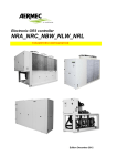
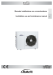
3.3.4 TO THE HEATING COIL (OPTIONAL)
3.3.4 ALLA BATTERIA DI RISCALDAMENTO
(OPTIONAL)
Joint diameter, inlet and outlet connections
are shown in the dimensional drawings. Each
heating coil is fitted with three-way on-off
valve controlled by a microprocessor
(Macrobase) in accordance with the
environmental temperature load.
Particular care must be taken in order to avoid,
for any reason, water freezing. For that reason
it is necessary to employ a proper low freezing
point mixtrure.
I diametri e le posizioni degli attacchi per i
collegamenti idraulici sono illustrate nei disegni
dimensionali.
Ogni batteria è provvista di valvola a tre vie onoff
controllata
tramite
microprocessore
(Macrobase) per il controllo del carico termico.
Bisognerà
porre
particolare
attenzione
affinchè, per qualsiasi motivo, l’acqua in essa
contenuta non geli. A tale scopo è necessario
aggiungere un’opportuna percentuale di
fluido anticongelante.
12
13
14
15
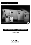
3.3.5 SCARICO DELLA CONDENSA
3.3.5 CONDENSATION DRAINAGE
Durante il fuzionamento in fase di raffreddamento, l'apparecchio sottrae umidità all'aria.
L'acqua di condensa che si raccoglie nella
vaschetta dovrà essere eliminata raccordando
l'apposito attacco o tubazione presente nella
macchina. La tubazione di scarico dovrà avere
una leggera pendenza (circa 3%) per
consentire un regolare deflusso dell'acqua. Si
dovrà inoltre prevedere un sifone che eviti il
ritorno di odori cattivi. Una volta terminata tale
operazione verificare la regolarità del
drenaggio versando dell’acqua nella bacinella
dalla parte più lontana al foro di scarico.
When the unit is in the cooling phase, it will
take humidity from the air. The condensation
water that collects in the tray has to be
eliminated by joining a pipe to the one on the
machine. This pipe should slant slightly (about
3%) to ensure a regular flow of the water. Also
install a trap to avoid the return of bad smells.
Once this operation is concluded, verify that
condensate is properly drained, filling the pan
with water in the furthest zone from the
draining hole.
3.3.6 COLLEGAMENTO ALL’UMIDIFICATORE
(VERSIONI HH)
3.3.6
Per le unità dotate di umidificatore collegare le
tubazione di carico e scarico dell'umidificatore
avendo cura che l'acqua di alimentazione sia
filtrata. L'umidificatore riconosce da solo la
durezza dell'acqua e automaticamente decide i
tempi di scarico dell'acqua ricca di sali.
Ulteriori indicazione potranno essere reperite
nel manuale di uso e manutenzione
dell'umidificatore (CDD).
For those units fitted with a humidifier,
connect its inlet and outlet pipes, making sure
the supply water is filtered. The humidifier can
detect water hardness and automatically
decides drainage times of the salt rich water.
For additional instructions see the humidifier's
use and maintenance manual (CDD).
ATTENZIONE:
NON
L’UMIDIFICATORE
CON
DEMINERALIZZATA !
WARNING: DO NOT FEED DEMINERALIZED OR
SOFTENED WATER INTO HUMIDIFIER !
ALIMENTARE
ACQUA
16
CONNECTION
VERSIONS)
TO
HUMIDIFIER
(HH
3.3.7 RACCOMANDAZIONI GENERALI PER I
COLLEGAMENTI IDRAULICI
3.3.7 GENERAL ADVICE ON WATER PIPE
CONNECTIONS
Quando ci si appresta a realizzare il circuito
idraulico sia esso per condensatore a piastre,
per la batteria di raffreddamento, per la
batteria di riscaldamento, per l'umidificatore o
per lo scarico della condensa è buona norma
attenersi alle seguenti prescrizioni e comunque
attenersi alla normativa nazionale o locale.
When the pipes have to be connected, whether
it is for the plate heat exchanger, cooling
battery, heating battery, humidifier or for the
drainage of condensation, it is always good
practice to follow these instructions and, in all
cases, comply with the national or local
standards.
-Raccordare le tubazioni all'unità tramite giunti
flessibili al fine di evitare la trasmissione delle
vibrazioni e compensare le dilatazioni termiche.
-Installare
sulle
tubazioni
i
seguenti
componenti:
- Use flexible joints to fit the pipes to the unit:
this will avoid transmitting vibrations and
compensate for thermal expansion.
- Install the following components on the pipes:
• stop cocks, temperature and pressure
indicators for routine maintenance and control
of the unit;
• rubinetti d'arresto, indicatore di temperatura e pressione per la normale
manutenzione e controllo del gruppo;
• pocket on inlet and outlet pipes for detecting
temperature, if the temperature indicators are
not fitted;
• pozzetto sulle tubazioni di ingresso ed uscita
per i rilievi di temperatura, qualora non
fossero presenti gli indicatori di temperatura;
• check valves (gates) to isolate the unit from
the water circuit;
• valvole di intercettazione (saracinesche) per
isolare l'unità dal circuito idraulico;
• metal mesh filter (on the inlet pipe) with a
maximum mesh of 1 mm, to protect the
exchanger from waste or impurities present in
the pipes;
• filtro metallico (tubazione di ingresso) a rete
con maglia non superiore a 1mm, per proteggere lo scambiatore da scorie o impurità
presenti nelle tubazioni;
• air valves, located in the highest parts of the
water circuit, to allow bleeding of substances
that cannot be condensed;
• valvole di sfiato da collocare nelle parti più
elevate del circuito idraulico, per permettere
lo spurgo degli incondensabili;
• gunbarrel and automatic filling valves to
• vaso di espansione e valvole di carico
automatica per il mantenimento della
pressione del sistema e per compensare le
dilatazioni termiche;
maintain system pressure and to compensate
for thermal expansion;
• drain cock and, where necessary, a drainage
tank to permit the emptying of the plant for
maintenance purposes or seasonal interludes.
• rubinetto di scarico e, ove necessario,
serbatoio di drenaggio per permettere lo
svuotamento dell'impianto per le operazioni
di manutenzione e le pause stagionali.
The installation of a safety valve on the water
circuit is strongly recommended. In the case of
serious problems in the system (such as the
outbreak of a fire), this valve will empty the
system thus avoiding the probability of an
explosion. Always connect the discharge
opening to a pipe whose diameter is no smaller
than that of the valve opening, and convey it
to zones where its jet can be of no harm to
people. Use a water-ethylene glycol mixture (in
the percentages given in Table II) to prevent
the formation of ice which would break the
exchangers.
E' vivamente consigliata l'installazione di una
valvola di sicurezza sul circuito idraulico. In caso
di anomalie gravi nell'impianto (ad es.
incendio) essa permetterà di scaricare il sistema
evitando possibili scoppi. Collegare sempre lo
scarico ad una tubazione di diametro non
inferiore a quello dell'apertura della valvola e
convogliarlo in zone nelle quali il getto non
possa recare danno alle persone. Usare miscele
di acqua-glicole (vedi Tab. II), per prevenire
formazioni di ghiaccio che possono provocare
rotture negli scambiatori.
17
3.4 COLLEGAMENTI ELETTRICI
3.4 ELECTRICAL POWER AND EARTHING
3.4.1 GENERALITA’
3.4.1 GENERAL
Prima di effettuare qualsiasi operazione su parti
elettriche assicurarsi che non vi sia tensione.
Prior to touching any electrical part, make
sure it is not live.
- Controllare visivamente che i circuiti elettrici
non siano stati danneggiati durante il
trasporto.
- Controllare che tutte le viti dei vari morsetti
siano ben fissate.
- Verificare che la tensione di alimentazione
corrisponda ai dati nominali dell'unità
(tensione, numero di fasi, frequenza) riportati
sulla targhetta a bordo macchina.
Per l'ingresso dei cavi utilizzare l'apposito foro
situato sul basamento dell’unità.
- Check visually that the electrical circuits have
not been damaged during transportation.
- Check that all screws on the various terminals
are well secured.
- Check that supply voltage corresponds to the
unit's nominal data (voltage, number of
phases, frequency) shown on the label on the
machine.
For cable entry, use the special hole placed on
the base of the units.
La sezione del cavo e le protezioni di linea devono essere conformi a quanto indicato nello
schema elettrico .
Cable section and line protections should
conform to the information given on the
wiring diagramme.
La tensione di alimentazione non deve subire
variazioni superiori a ±5% e lo squilibrio tra le
fasi deve essere sempre inferiore al 2%.
Se ciò non dovesse verificarsi prendere contatto
con il nostro Ufficio Tecnico per la scelta di
opportune protezioni.
Supply voltage should not be subject to
variations greater than ± 5% and the
unbalance between phases should always be
lower than 2%.
To the contrary, contact our Technical Office to
decide upon the most appropriate protection.
Il funzionamento deve avvenire entro i valori
sopra citati: in caso contrario la garanzia viene
a decadere immediatamente.
The unit should function within the values
indicated above: to the contrary, the
guarantee is immediately deemed ineffective.
I collegamenti elettrici devono essere realizzati
in accordo con le informazioni riportate sullo
schema elettrico allegato all'unità.
Il collegamento a terra è obbligatorio per
legge. L'installatore deve provvedere al
collegamento del cavo di terra con la barra di
terra situata nel quadro elettrico.
L'alimentazione del circuito di controllo è
derivata dalla linea di potenza tramite un
trasformatore situato nel quadro elettrico.
Il circuito di controllo è protetto da un
interruttore automatico dedicato.
Gli schemi elettrici vengono allegati alla macchina all'interno del quadro elettrico. Il cavo di
alimentazione dovrà essere connesso ai
morsetti di ingresso.
Electrical connections should be carried out
following the instructions given in the wiring
diagramme attached to the unit.
Earthing is compulsory by law. The installer
shall connect the earth cable to the earth bar
on the electric panel.
Power for the control circuit is shunted from
the main line through a transformer located on
the electric panel.
The control circuit is protected by a circuit
breaker.
Wiring diagrammes are attached to the
machine, inside the electric panel. The power
cable has to be connected to the input
terminals.
18
3.4.2 ALLARMI E CONSENSI ESTERNI
3.4.2 ALARM AND EXTERNAL CONSENTS
E’ presente in morsettiera il contatto pulito di
allarme generale.
Qualora si desideri effettuare un ON-OFF
remoto dell'unità è necessario collegare il
consenso esterno ai contatti indicati sullo
schema elettrico.
N.B.:il consenso esterno disabilita il controllo
ON-OFF sul frontalino delle unità.
There is inside terminal block the potential free
conctat of general alarm.
If you wish to have a remote ON-OFF for the
unit, you will have to connect the external
consent to contacts indicated in the wiring
diagramme.
N.B.: The external consent disables the ON-OFF
control on the small front panel of the unit.
Quando si effettuano i collegamenti descritti
attenersi scrupolosamente a quanto riportato
nello schema elettrico.
When carrying out the connections described,
follow exactly the instructions given in the
wiring diagramme.
3.5 CONTROLLO A MICROPROCESSORE
3.5 MICROPROCESSOR CONTROL
In tutte le unità DAT'AIR viene montato il controllo:
The following controls are installed on all
DAT'AIR units :
-MACROBASE per gestire tutte le funzioni
principali necessarie;
- MACROBASE, to manage all the main
necessary functions;
-CDD per gestire il controllo dell'umidità e
comunica direttamente con MACROBASE.
- CDD, to manage humidity control and to
communicate directly with MACROBASE.
Informazioni dettagliate sul funzionamento di
tali controlli possono essere reperite nel relativo
manuale fornito a corredo dell'unità.
You will find more detailed information about
these controls in the relative manual provided
with the unit.
3.5.1 INTERFACCIA SERIALE RS 422
(OPTIONAL).
3.5.1 RS 422 SERIAL INTERFACE
(OPTIONAL).
Per tutte le unità è disponibile a richiesta la
scheda seriale per supervisione o teleassistenza
tramite elaboratore elettronico.
On request, units can be provided with serial
interface for supervisory or telemaintenance
system management.
19
4. LIMITI DI FUNZIONAMENTO
4. OPERATING LIMITS
Le unità sono progettate per poter operare in
maniera soddisfacente in un ampio campo di
funzionamento. Ciò nonostante vi sono dei
limiti, sia per le temperature dell’aria utenza
che per quelle dell’aria o dell’acqua esterna che
non devono essere oltrepassati: in caso
contrario l’unità potrebbe arrestarsi per
intervento degli organi di protezione o
addirittura subire dei seri danneggiamenti. Tali
limiti sono riportati in Tab. I.
Nel caso si necessitasse di operare al di fuori di
tali limiti, si prega contattare il ns. Ufficio
Tecnico.
Units are designed to work properly in a wide
operation range. Anyway it is highly
recommended not to exceed operation limits
concerning user air temperature and source air
and water temperature: if this situation should
occur, unit may stop because of safety devices
or in the worst case may have a serious failure.
These limits are reported in Tab. I.
If in the need to exceed these limits, please
contact our Technical Department.
4.1 CONDENSATION WATER
TEMPERATURE
4.1 TEMPERATURA ACQUA DI
CONDENSAZIONE
The value of the water flow rate provided by
the units *EDW refers to a medium thermal
difference between input and output equal to
20°C in relation to the dissipation power of
machines that can operate with well water.
The minimum permitted thermal difference is
12°C; lower values could cause inadmissible
pressure drops with the danger of erosion
phenomena in the exchanger; higher values
could give rise to an excessive increase in
condensation temperature.
For *EDR units running of tower water or on a
closed circuit, the designed thermal difference
is 5°C; lower values could cause inadmissible
pressure drops with the danger of erosion
phenomena in the exchanger; higher values
could give rise to an excessive increase in
condensation temperature.
La portata d'acqua fornita per le unità *EDW
si riferisce ad un salto termico medio tra
ingresso ed uscita di 20°C in relazione alla
potenza da dissipare per le macchine adatte al
funzionamento con acqua di pozzo.
Il salto termico minimo ammesso è di 12 °C;
valori minori potrebbero generare perdite di
carico inammissibili con pericolo di fenomeni di
erosione nello scambiatore; valori maggiori
potrebbero aumentere eccessivamente la
temperatura di condensazione.
Per le unità *EDR ad acqua di torre o a circuito
chiuso il salto termico di progetto è di 5°C;
valori minori potrebbero generare perdite di
carico inammissibili con pericolo di fenomeni di
erosione nello scambiatore; valori maggiori
potrebbero aumentere eccessivamente la
temperatura di condensazione.
4.2 OUTDOOR AIR TEMPERATURE (*EDA)
4.2 TEMPERATURA ARIA ESTERNA (*EDA)
La temperatura dell'aria esterna può variare da
un massimo di 40°C ad un minimo di 15°C. Per
valori inferiori bisogna ricorrere a sistemi di
controllo della temperatura di condensazione
come un regolatore di giri del ventilatore del
condensatore (per CRAX) o con valvola di
controllo condensazione ad allagamento (per
CRCF).
Outdoor air temperature can range from a
maximum of 40°C to a minimum of 15°C. In
the case of lower values it will be necessary to
revert to systems to control condensation
temperature i.e. a condenser fan rev regulator
(for CRAX) or a Kingston condensation control
valve (for CRCF).
4.3 TEMPERATURA ARIA AMBIENTE
4.3 ROOM AIR TEMPERATURE
La temperatura minima di ingresso dell'aria alle
condizioni di portata nominale è di 18°C, valori
minori potrebbero causare il formarsi di brina
all'evaporatore
con
conseguente
danneggiamento dell'unità.
Minimum air inlet temperature under nominal
capacity conditions is 18°C; lower values could
give rise to the formation of frost on the
evaporator and consequently damage the unit.
20
Maximum air inlet temperature under nominal
capacity conditions is 30°C; higher values could
give rise to overheating of the compressor.
La temperatura massima di ingresso dell'aria
alle condizioni di portata nominale è di 30°C,
valori maggiori potrebbero causare il
surriscaldamento del compressore.
4.4 AIR FLOW RATE
4.4 PORTATA ARIA
The units have been designed to function with
the nominal air flow rate with a variation of ±
15%; different values could give rise to the
formation of frost on the evaporator and
consequent malfunctioning.
Le unità sono state progettate per funzionare
con la portata d'aria nominale con una
variazione del ±15% valori diversi possono
causare la formazione di brina all'evaporatore
ed anomalie di funzionamento.
4.5 WATER QUALITY
4.5 QUALITA' DELL'ACQUA
Working with well water (or river water) could
give rise to corrosion and scaling due to the
quality of the water itself. To this end, an
analysis of the water is recommended to
determine the pH values, conductivity, the
presence of ammonium ions, the presence of
sulphur and chlorine, total hardness, etc., and,
if necessary, it should be chemically treated.
Qualora si operi con acqua di pozzo (o di
fiume), si potrebbero presentare problemi di
corrosione e di incrostazioni dovuti alla qualità
dell'acqua. A tal proposito si consiglia di
effettuare un'analisi per verificare i valori di pH,
conduttività elettrica, presenza di ioni
ammonia, presenza di zolfo e cloro, durezza
totale, ecc. e di operare eventualmente un
opportuno trattamento chimico.
TABELLA I - LIMITI DI FUNZIONAMENTO
TABLE I - OPERATION LIMIT
Lato utenze/User side
Temperatura aria ingresso °C
Inlet air temperature °C
Lato sorgente/Source side
Acqua di pozzo/Well water *EDW
18
max Lato sorgente/Source side
Temperatura aria ingresso °C
30 Inlet air temperature °C
min
Lato sorgente/Source side
max Acqua di torre/Tower water *EDR
min
Temperatura acqua ingresso °C
Inlet water temperature °C
10
30
Inlet water temperature °C
25
50
Outlet water temperature °C
15
40
min
max
19
47
27
50
3
8
Temperatura acqua in uscita °C
Salto termico acqua °C (‘)
Water thermal difference °C (‘)
max
Temperatura acqua ingresso °C
Temperatura acqua in uscita °C
Outlet water temperature °C
min
Salto termico acqua °C (‘)
12
Water thermal difference °C (‘)
25
(‘) Il salto termico acqua deve comunque garantire i limiti di temperatura acqua ingresso-uscita.
(‘) Water thermal difference must always guarantee water inlet-outlet operation limit.
TABELLA II - PUNTO DI CONGELAMENTO PER MISCELE DI ACQUA-GLICOLE ETILENICO
TABLE II - FREEZING POINT FOR WATER-ETHYLENE GLYCOL MIXTURES
Percentuale in peso
Weight percentage
10
20
30
40
50
-4,8
-9,9
-17,2
-26,6
-38,3
%
Punto di congelamento
Freezing point
°C
21
5. AVVIAMENTO
5. START UP
5.1 CONTROLLI PRELIMINARI
5.1 PRELIMINARY CONTROLS
-Verificare che l'allacciamento elettrico sia stato
eseguito in maniera corretta e che tutti i
morsetti siano serrati strettamente.
- Check that the electrical connection has been
carried out correctly and that all terminals are
tightly secured.
- Verificare che la tensione sui morsetti di linea
sia quella corretta ±5% controllabile con un
tester. Se la tensione fosse soggetta a variazioni
frequenti prendere contatto con il nostro
Ufficio Tecnico per la scelta di opportune
protezioni.
- Use a tester to check that the voltage on the
line terminals is correct ± 5%. If the voltage is
subject to frequent variations, contact our
Technical Office to decide upon the most
appropriate protection.
-Controllare che non vi siano perdite di fluido
refrigerante, eventualmente tramite l'ausilio di
cercafughe.
- Check there are no refrigerant leakages, using
a leak detector if necessary.
- Verificare la corretta alimentazione delle resistenze del carter (se presenti).
- Check the correct voltage of the casing's
heating resistors (if there are any).
L'inserimento delle resistenze deve essere fatto
almeno 12 ore prima dell'avviamento, ed
avviene automaticamente alla chiusura del
sezionatore generale.
The heating resistors should be activated at least
12 hours prior to start up; this occurs
automatically when you turn the main switch
on.
Per controllare il corretto funzionamento delle
resistenze verificare che la parte inferiore dei
compressori sia calda ed in ogni caso sia ad
una temperatura di 10÷15°C superiore a quella
ambiente.
To verify that the resistors are working properly,
check that the bottom part of the compressors
is hot and, in all cases, at a temperature 1015°C higher than room temperature.
- Check that all water pipe connections have
been carried out correctly and in compliance
with the indications on the label on the
machine.
-Verificare che gli eventuali collegamenti
idraulici siano stati eseguiti in maniera corretta,
rispettando le indicazioni sulle targhette a
bordo macchina.
-Verificare che tutti i rubinetti presenti nel
circuito frigorifero siano aperti.
-Check that all shut-off valves in the refrigerant
circuit are open.
-Verificare che l'impianto idraulico (*EDW,
*EDR, *FC) sia stato sfiatato, eliminando ogni
eventuale
residuo
d'aria,
caricandolo
gradualmente e aprendo i dispositivi di sfiato
sulla parte superiore che l'installatore avrà
avuto cura di predisporre assieme ad un vaso di
espansione di adeguata capacità.
- Check that the water pipe system (*EDW,
*EDR, *FC) has been bled, eliminating all air
residuals, gradually charging it and opening the
bleed devices on the top, fitted by the installer
together with a gunbarrel of suitable capacity.
Att.ne: prima di procedere alla messa in
funzione verificare che tutti i pannelli di
chiusura dell'unità siano al loro posto e serrati
con l'apposita vite.
Attention: prior to starting up, check that all
panels enclosing the unit are in place and
screwed down properly.
22
5.2 MESSA IN FUNZIONE
5.2 STARTING UP
- Verificare che sia accesa la spia "line" di macchina sotto tensione.
- Check that the "line" indicator light is on,
meaning the machine is live.
- Verificare i valori di taratura.
- Check set-point values.
- Per quanto riguarda la vera e propria messa in
funzione procedere come segue: premere il
tasto "ON" sul pannello frontale del controllo a
microprocessore.
In tale situazione, se il relè di sequenza fase
(posto nel quadro elettrico) da consenso, il
ventilatore si avvia, altrimenti si dovrà
provvedere a invertire due fasi. Dopo un ritardo
di primo avviamento, qualora ci sia il consenso
del termostato di servizio o del controllo
umidità il compressore si avvierà.
- For the actual start up, proceed as follows:
press the "ON" key on the front panel of the
microprocessor control unit.
Si raccomanda di non togliere tensione all'unità
durante i periodi di arresto ma solo nel caso di
pause prolungate (ad. es. fermate stagionali).
Per lo spegnimento temporaneo dell'unità
seguire attentamente le indicazioni riportate al
paragrafo 5.5.
Do not leave the unit without electricity during
normal stop periods; leaving it without
electricity should only be done in the case of
long pauses, i.e. seasonal stops. For the
temporary turn off of the unit follow carefully
the instructions given in paragraph 5.5.
5.3 VERIFICHE DURANTE IL FUNZIONAMENTO
5.3 CHECKS WHEN RUNNING
-Dopo qualche minuto dall'avviamento dei
compressori, verificare che la temperatura di
condensazione
sia
approssimativamente
attorno ai 42÷50°C: tale operazione può essere
eseguita tramite l'ausilio di un manometro.
-Per le unità *FC controllare la differenza di
temperatura tra ingresso e uscita dell'acqua.
-Verificare che la temperatura indicata sul
display sia uguale a quella dell'aria in ripresa.
-Verificare il senso di rotazione dei ventilatori:
se esso non fosse rispondente a quello di
progetto, togliere tensione ed invertire due fasi
del cavo tripolare in ingresso: non modificare
mai i collegamenti elettrici interni pena il
decadimento della garanzia.
- After a few minutes from starting the
compressors, check condensation temperature
is approximately 42-50°C: this can be done
using a gauge.
At this point, if the sequence phase relay (place
in the electric board) gives connection the fan
will start, otherwise invert two phases. After a
delay of the first start up, if consent is given by
the service thermostat or by the humidity
control, the compressor will start.
- For the *FC units check temperature
difference between water inlet and outlet.
- Check that the temperature indicated on the
display is the same as that of the intake air.
-Check the fans rotation. If the rotation is
incorrect, disconnect the main switch and
change over any two phases of the incoming
main supply to reverse motor rotation: do not
alter the internal wiring of the unit otherwise
warranty will terminate immediately.
-If the unit shoul be provided with electric
heaters, check their operation measuring the
power consumption
-Nel caso fossero presenti le resistenze
elettriche verificarne l’intervento misurando
l’assorbimento elettrico delle stesse
23
5.4 VERIFICA DELLA CARICA DI REFRIGERANTE
5.4 CHECKING REFRIGERANT CHARGE
-Verificare,
dopo
qualche
ora
di
funzionamento, che la spia del liquido abbia la
corona verde: una colorazione gialla indica
presenza di umidità nel circuito. In questo caso
si rende necessaria la disidratazione del circuito
da parte di personale qualificato.
-Verificare che non appaiano bolle alla spia del
liquido. Il passaggio continuo di bolle può
indicare scarsità di refrigerante e la necessità di
reintegro. E' comunque ammessa la presenza
di qualche bolla.
-Dopo qualche minuto dall'avviamento dei
compressori verificare che la temperatura di
condensazione misurata al manometro sia di:
13÷17°C superiore alla temperatura dell'aria
esterna (versione *EDA) e di 5÷7°C superiore
alla temperatura dell'acqua in uscita dal
condensatore (versioni*EDW, *EDR).
Verificare inoltre che la temperatura di
evaporazione sia circa 15÷20°C inferiore alla
temperatura dell'aria in ingresso.
-Verificare che il surriscaldamento del fluido
frigorifero sia compreso tra 5 e 7 °C: per far
ciò:
1) rilevare la temperatura indicata da un
termometro a contatto posto sul tubo di
aspirazione del compressore;
2) rilevare la temperatura indicata sulla scala di
un manometro connesso anch'esso in
aspirazione (temperatura di saturazione
corrispondente alla pressione di aspirazione);
per le unità con fluido frigorifero R407c
riferirsi alla scala del manometro indicata con
la sigla D.P. (Dew Point).
La differenza tra le temperature così trovate
fornisce il valore del surriscaldamento.
- After a few hours of functioning, check that
the fluid indicator has a green crown: yellow
indicates the presence of humidity in the
circuit. In such an event it will be necessary to
dry out the circuit (by qualified personnel).
- Check there are no bubbles in the fluid
indicator. The constant passage of bubbles
could mean a lack of refrigerant and the need
to top up. The presence of a few bubbles is
allowed.- After a few minutes from starting the
compressors
check
that
condensation
temperature, measured on the gauge, is 1317°C higher then outside air temperature
(*EDA version) and 5-7°C higher than the
water in output from the condenser (*EDW,
*EDR version).
Also check that evaporation temperature is
approximately 15-20°C lower than inlet air
temperature.
-Verificare che il sottoraffreddamento del
fluido frigorifero sia compreso tra 5 e 7 °C: per
far ciò:
1) rilevare la temperatura indicata da un
termometro a contatto posto sul tubo di
uscita dal condensatore;
2) rilevare la temperatura indicata sulla scala di
un manometro connesso sulla presa del
liquido
all’uscita
del
condensatore
(temperatura di saturazione corrispondente
alla pressione di uscita dal condensatore); per
le unità con fluido frigorifero R407c riferirsi
alla scala del manometro indicata con la sigla
B.P. (Bubble Point).
La differenza tra le temperature così trovate
fornisce il valore del sottoraffreddamento.
-Check that refrigerant subcooling on the
condenser is about 5-7 °C: this operation can
be done in this way:
1) read the temperature value shown by a
contact thermometer on the refrigerant outlet
of the condenser;
2) read the temperature value shown by a
graduated pressure gauge set on the outlet
too (this value is the saturated temperature
corresponding to the condenser outlet
pressure); for unit with refrigerant R407c
refer to centigrade scale marked with B.P.
(Bubble Point).
The difference between this two values
represents the refrigerant liquid subcooling.
-Check that refrigerant superheat on the
evaporator is about 5-7 °C: this operation can
be done in this way:
1) read the temperature value shown by a
contact thermometer with the probe on the
suction pipe of the compressor;
2) read the temperature value shown by a
graduated pressure gauge set on the suction
side too (this value is the saturated
temperature corresponding to the suction
pressure); for unit with refrigerant R407c
refer to centigrade scale marked with D.P.
(Dew Point).
The difference between this two values
represents the refrigerant gas superheat.
24
TABELLA III - CARICA DI REFRIGERANTE R22 - R407c [kg]
TABLE III - UNITS REFRIGERANT CHARGE R22 - R407c [kg]
MODELLO
MODEL
*EDA(‘)
*EDW
*EDR
50
80
110
150
170
100
140
180
230
260
350
440
520
2.2
0.8
1.0
2.4
1.0
1.3
2.6
1.2
1.5
4.0
1.6
1.9
4.4
2.0
2.4
2.6
1.2
1.5
4.0
1.6
1.9
4.4
2.0
2.4
4.7
2.3
2.7
8.3
3.3
3.8
8.9
3.4
3.9
9.6
3.6
4.2
10.5
4.0
4.5
MODELLO 280
MODEL
*EDA(‘)
8.0
*EDW
3.2
*EDR
3.8
360
460
600
760
860
960
8.8
4.0
4.8
9.4
4.6
5.4
16.6
6.6
7.6
17.8
6.8
7.8
19.2
7.2
8.4
21.0
8.0
9.0
(‘) Completo di unità condensante
(‘) Fitted with condensing unit
TABELLA IV - TARATURA DEGLI ORGANI DI CONTROLLO E SICUREZZA
TABLE IV - CONTROL AND SAFETY DEVICES FACTORY SETTINGS
ORGANO DI CONTROLLO/SICUREZZA
ATTIVAZIONE
DIFFERENZIALE
REINSERZIONE
°C
24
2
--
Umidostato di servizio (versioni HH)
Control Humidostat (HH versions) %UR
Pressostato di massima
50
2
-manuale
26
7.7
CONTROL/SAFETY DEVICE
Termostato di servizio
Control Thermostat
High pressure switch
Pressostato di minima
Low pressure switch
bar
bar
SET POINT
DIFFERENTIAL
RESET TYPE
manual
automatico
0.7
25
1.0
automatic
OEDA / UEDA Schema circuito frigorifero
OEDA / UEDA Refrigerant circuit diagram
26
OEDW-R / UEDW-R Schema circuito frigorifero
OEDW-R / UEDW-R Refrigerant circuit diagram
27
5.5 ARRESTO DEL GRUPPO
5.5 TO STOP
La fermata del gruppo avviene premendo il
tasto "OFF" sul pannello frontale.
Press the "OFF" key on the front panel to stop
the unit.
Att.ne: per la fermata del gruppo non togliere
tensione tramite l'interruttore generale: così facendo le resistenze del carter non verrebbero
alimentate con pregiudizio per l'integrità del
compressore alla ripartenza.
Attention: to stop the unit do not turn off
by means of the main switch: if you do, the
casing heating resistors would no longer be
fed and would hence prejudice the proper
working order of the compressor when
starting up the next time.
6. TARATURA DEGLI ORGANI DI
CONTROLLO E SICUREZZA.
6. CALIBRATING THE CONTROL AND
SAFETY DEVICES
6.1 GENERALITA'
6.1 GENERAL
Tutte le apparecchiature di controllo e sicurezza
sono tarate e collaudate in fabbrica prima della
spedizione della macchina. Tuttavia dopo che
l'unità ha funzionato per un ragionevole
periodo di tempo, si può eseguire un controllo
dei dispositivi di funzionamento e di sicurezza. I
valori di taratura sono riportati nella Tabella IV.
All the equipment used for controlling and for
safety are calibrated and tested in the factory
before the machine is shipped. However, after
the unit has been running for a reasonable
length of time, you can check the operating
and safety devices. Their set-point values are
given in Table IV.
Tutte le operazione di controllo devone essere
effettuate ESCLUSIVAMENTE DA PERSONALE
QUALIFICATO: valori erronei di taratura o
manovre errate possono arrecare seri
danneggiamenti all'unità e alle persone.
All control operations must ONLY be carried
out by SKILLED PERSONNEL: erroneous setpoint values regarding manoeuvres could
seriously damage the unit as well as be
hazardous for people.
6.2 PRESSOSTATO DI MASSIMA
6.2 MAXIMUM PRESSURE SWITCH
Il pressostato di alta pressione arresta il
compressore quando la pressione in mandata
supera il valore di taratura.
Per verificarne il funzionamento spegnere, con
il compressore in funzione, il ventilatore
dell'unità
condensante
(*EDA)
oppure
l'alimentazione dell'acqua (*EDW, *EDR),
osservando sul manometro di mandata del
compressore (precedentemente installato) che
l'intervento del pressostato (arresto del
compressore) avvenga in corrispondenza del
valore di taratura.
The high pressure pressure switch will stop the
compressor in the event of delivery pressure
exceeding the set-point value.
To verify its correct working order turn the
condenser unit fan (*EDA) or the water supply
(*EDW, *EDR) off while the compressor is
running: keep an eye on the compressor
delivery gauge (installed previously) to see that
the pressure switch triggers when it reaches
the set-point value.
Attenzione: se durante tale operazione il
dispositivo di sicurezza non dovesse intervenire,
occorre essere pronti ad aprire l'interruttore del
compressore per arrestarne il funzioneamento.
Attention: during this operation, if the safety
device does not come into play, you must be
ready to switch the compressor off.
Il riarmo è manuale e può avvenire solo quando
la pressione è scesa al disotto del valore di
intervento meno il differenziale. Verificare
inoltre che i manometri installati funzionino
correttamente.
Resetting is manual and can only take place
when pressure has dropped below the
intervention value less the differential.Also
check that the gauges installed are working
correctly.
28
6.3 PRESSOSTATO DI MINIMA
6.3 MINIMUN PRESSURE SWITCH
Il pressostato di bassa pressione arresta il compressore quando la pressione di aspirazione
scende al disotto del valore di taratura. Per
verificarne il funzionamento, avviare il
compressore e, dopo un tempo di circa 5
minuti, chiudere lentamente la linea del liquido
corrispondente, osservando sul manometro di
aspirazione del compressore (precedentemente
installato) che l'intervento del pressostato
(arresto del compressore) avvenga in
corrispondenza del valore di taratura.
The low pressure pressure switch will stop the
compressor in the event of suction pressure
dropping below the set-point value.
To verify its proper working order turn the
compressor on and, after 5 minutes, slowly
close the relative liquid line, keeping an eye on
the compressors' suction gauge (installed
previously) to see that the pressure switch
triggers (stopping the compressor) when it
reaches the set-point value.
Attenzione: durante tale operazione, se il
dispositivo di sicurezza non dovesse intervenire,
occorre essere pronti ad aprire l'interruttore del
compressore per arrestare il compressore
stesso.
Attention: during this operation, if the safety
device does not come into play, you must be
ready to switch the compressor off.
Il riarmo è automatico ed avviene alla pressione
di intervento più il differenziale. Verificare
inoltre che i manometri installati funzionino
correttamente.
Resetting is automatic and takes place when
the intervention pressure plus the differential is
reached. Also check that the gauges installed
are working correctly.
6.4 IL TERMOSTATO
6.4 THERMOSTAT
Il termostato è una funzione compresa nel controllo del microprocessore.
Per verificarne il funzionamento, controllare
con un termometro campione in ingresso allo
scambiatore utenza che il valore misurato
corrisponda a quello visualizzato sul display del
controllo a microprocessore. Verificare inoltre,
che l'intero gruppo si arresti al raggiungimento
del valore di taratura (vedi Tabella IV sulle
tarature): ad es. con valore di set-point di
21,5°C e banda differenziale 1°C, il
compressore si fermerà a 21,5°C e ripartirà a
22,5°C.
The thermostat is one of the microprocessor's
functions.
To verify its correct working order, check, with
a standard thermometer at the user exchanger
input, that the value measured corresponds to
that visualized on the display of the
microprocessor control. Verify also that the
whole unit stops when it reaches the set-point
value (see set-point Table IV): for instance with
the set-point value of 21.5°C and a differential
band of 1°C, the compressor will stop at
21.5°C and restart at 22.5°C.
6.5 TIMER ANTIRICICLO
6.5 ANTIRECYCLE TIMER
E' un dispositivo con la funzione di impedire
avvii ed arresti del compressore troppo
frequenti dovuti a pendolamenti di variabili
esterne quali l'aria trattata. Tale parametro è
compreso nelle funzioni del microprocessore.
Esso permette l'avviamento del compressore
dopo una sua fermata, solamente quando sia
trascorso un determinato periodo di tempo (6
minuti circa).
Non modificare mai il valore di ritardo
impostato in fabbrica: valori errati potrebbero
causare seri danneggiamenti all'unità.
This device is to prevent a too frequent starting
and stopping of the compressor due to the
oscillation of external variables such as treated
air.
This parameter is included in the
microprocessor's functions. It permits starting
of the compressor after one of its stops, only
when a certain length of time has elapsed
(approx. 6 minutes).
Never alter the delay value set in the factory:
wrong values could seriously damage the unit.
29
6.6 UMIDIFICATORE (VERSIONI HH)
6.6 HUMIDIFIER (HH VERSIONS)
Tale
dispositivo
permette
il
controllo
dell'umidità ambiente tramite una sonda posta
sulla ripresa dell'aria. Questa funzione è svolta
dal controllo CDD e permette, a seconda delle
necessità, di deumidificare o umidificare l'aria.
Il controllo potrà quindi far avviare il compressore anche se la temperatura ambiente è
quella di set, contemporaneamente verranno
attivate le resistenze elettriche o la batteria ad
acqua calda.
Per informazioni dettagliate su CDD possono
essere reperite nel relativo manuale fornito a
corredo dell'unità.
With this device it is possible to control room
humidity by means of a probe placed on the air
intake. This function is performed by the CDD
control and, according to necessity, it will
either dehumidify or humidify the air.
The CDD control can start the compressor even
if room temperature is the set one; the
electrical resistors or the hot water battery will
be started simultaneously.
You will find more details about CDD in the
manual provided with the unit.
6.7 SENSORE FLUSSO ARIA
6.7 AIR FLOW SENSOR
Questo dispositivo previene il brinamento della
batteria evaporante causato dalla mancanza o
scarsità di portata d’aria. Il controllo è
effettuato da un sensore PTC allo stato solido
integrato nelle funzioni del microprocessore
che attiva un allarme e arresta l’unità nel caso
di mancanza del flusso aria.
This device avoids freezing of the evaporating
coil due to total absence or insufficient air
flow. It is controlled by a solid state PTC sensor
connected with microprocessor control; an
alarm is trigged and the unit is stopped if the
air flow is lacking.
6.8 SENSORE FILTRI SPORCHI (OPTIONAL)
6.8 CLOGGED FILTER SENSOR (OPTIONAL)
This device is used to verify the level of
clogging of the air filter, measuring the drop in
pressure both up and down stream from it.
It will signal, by means of an acoustic alarm
and a signal on the display, the need to replace
the filter. The machine will, however, continue
to function.
Tale dispositivo permette di verificare il livello di
intasamento del filtro dell'aria misurando la caduta di pressione a monte e a valle del filtro.
Il controllo segnalerà, tramite un avviso
acustico e un segnale sul display, la necessità di
sostituire il filtro. La macchina continuerà
comunque a funzionare.
Attention: a clogged filter will mean a
reduction in capacity and, hence, in machine
efficiency; the filter should be cleaned in the
shortest time possible from the moment the
"clogged filter" signal is given.
Attenzione: lo sporcamento del filtro causa una
diminuzione di portata e quindi di resa della
macchina; consigliamo il ripristino del filtro in
tempi più rapidi possibile dal momento della
segnalazione di "filtri sporchi".
30
7. MANUTENZIONE E CONTROLLI
PERIODICI
7. MAINTENANCE AND PERIODIC
CONTROLS
7.0 AVVERTENZE
7.0 WARNINGS
Prima di effettuare qualsiasi intervento
sull'unità o di accedere a parti interne,
assicurarsi di aver tolto l'alimentazione elettrica.
Before any work is carried out on the unit
or before accessing any parts inside it,
make sure the electricity has been turned
off.
La tubazione di mandata del compressore si
trova a temperatura elevata. Prestare
particolare attenzione quando si operi nelle sue
vicinanze.
The compressor's delivery pipes are very
hot. Please take care when working near
them.
Dopo le operazioni di manutenzione richiudere
sempre l'unità tramite le apposite pannellature,
fissandole con le viti di serraggio.
When maintenance has been completed,
always enclose the unit with its panels,
fixing them with the securing screws.
Tutte le operazioni descritte in questo capitolo
DEVONO ESSERE SEMPRE ESEGUITE DA
PERSONALE QUALIFICATO.
All the operations described in this chapter
MUST ALWAYS BE CARRIED OUT BY
SKILLED PERSONNEL.
7.1 GENERALITA'
7.1 GENERAL
E' buona norma eseguire i seguenti controlli
periodici
per
verificare
il
corretto
funzionamento dell'unità:
It is good practice to carry out the following
periodic controls to check that the unit is in
proper working order:
-Verificare il funzionamento di tutte le apparecchiature di controllo e di sicurezza come precedentemente descritto.
(Mensilmente).
- Check the proper working order of all the
control and safety devices, as described
previously.
(Monthly)
- Controllare il serraggio dei morsetti elettrici
sia all'interno del quadro elettrico che nelle
morsettiere dei compressori. Devono essere
periodicamente puliti i contatti mobili e fissi dei
teleruttori e, qualora presentassero segni di
deterioramento, vanno sostituiti.
(Mensilmente)
- Check the tightness of the terminals both
inside the electrical panel and on the
compressors' terminal boards. Remote switch
contacts must be cleaned regularly and
replaced if there are any signs of deterioration.
(Monthly)
-Controllare la carica di refrigerante attraverso
la spia del liquido.
(Mensilmente).
- Check the refrigerant charge on the fluid level
indicator.
(Monthly)
-Verificare che non vi siano perdite d'acqua nel
circuito idraulico.
(Mensilmente)
- Check there are no water leakages in the
water circuit. (Monthly)
-Se l'unità deve rimanere per un lungo periodo
fuori servizio, scaricare l'acqua dalle tubazioni e
dagli scambiatori di calore (*EDW, *EDR, *FC).
Questa operazione è indispensabile qualora
durante il periodo di fermata dell'unità si
prevedono temperature ambiente inferiori al
punto di congelamento del fluido utilizzato.
(Tipica operazione stagionale)
- If the unit is not to be used for a very long
time, drain away the water from the heat
exchanger pipes (*EDW, *EDR, *FC). This is
essential if, during the period the unit is not
being used, room temperatures are expected to
drop below the fluid's freezing point.
(Typical seasonal operation)
31
-Controllare il riempimento circuiti acqua.
(Mensilmente).
-Check water circuit level.
(Monthly)
-Controllare i
compressori.
(Mensilmente)
-Check the
resistors.
(Monthly)
riscaldatori
del
carter
dei
compressors'
casing
heating
-Effettuare la pulizia dei filtri metallici nelle
tubazioni idrauliche.
(Mensilmente).
-Clean the metal filters on the water pipes.
(Monthly)
-Controllare sulla spia del liquido l'indicatore di
umidità (verde=secco, giallo=umido); se
l'indicatore non fosse verde, come indicato
sull'adesivo della spia, sostituire il filtro.
(Ogni 4 mesi).
-Check the humidity indicator (green = dry,
yellow = damp) on the fluid indicator; if it is
not green, as shown on the indicator sticker,
replace the filter.
(Every 4 months)
-Controllare la tensione e l’usura delle cinghie
di trasmissione. Per ciò che concerne la
tensione
delle
cinghie,
premere
perpendicolarmente alla cinghia nel punto
centrale con una forza di circa 5 Kg. Lo
spostamento della cinghia rispetto alla
posizione iniziale dovrà essere di circa 10-12
mm (si veda la figura sottoriportata).
(Ogni 4 mesi).
-Check tension and wear drive belts. For what
concerning belt tension, push perpendiculary
belt in the central point applying a 5 Kg force.
Belt shold move from its starting position of
10-12 mm (see picture below).
(Every 4 month)
-Controllare lo stato, il
l’allineamento delle giranti
pulegge.
(Ogni 4 mesi).
fissaggio
ventilatori
-Check mounting of fan blades and pulleys.
(Every 4 month)
-Controllare che il rumore
macchina sia regolare.
(Ogni 4 mesi).
emesso
e
e
-Check that the noise made by the machine is
normal.
(Every 4 months)
dalla
-Check filter condition.
(Monthly)
-Controllare lo stato dei filtri.
(Mensilmente).
10-12 mm
32
90°
5 kg
7.2 RIPARAZIONI DEL CIRCUITO
7.2 REPAIRS ON THE COOLING CIRCUIT
FRIGORIFERO
Nel caso si fossero effettuate riparazioni del
circuito frigorifero si devono effettuare le
seguenti riparazioni:
-prova di tenuta;
-vuoto ed essiccamento del circuito frigorifero;
-carica di refrigerante.
If any repairs have been made to the cooling
circuit it will be necessary to carry out the
following operations:
-leakage test;
-creating vacuum and drying the cooling
circuit;
-refrigerant charge.
Nel caso si debba scaricare l'impianto
recuperare
sempre,
tramite
apposita
attrezzatura, il refrigerante presente nel
circuito.
If you have to drain the system, always save
the refrigerant present in the circuit using the
special device.
7.2.1 PROVA DI TENUTA
7.2.1 LEAKAGE TEST
Caricare il circuito frigorifero con azoto anidro,
tramite bombola munita di riduttore, fino a
raggiungere la pressione di 15 bar.
Eventuali perdite dovranno essere individuate
tramite cercafughe a bolle. L'insorgere di bolle
o schiuma indica la presenza di fughe
localizzate.
Se durante la prova si sono dunque individuate
le fughe, scaricare il circuito prima di eseguire
le saldature con leghe appropriate.
Fill the cooling circuit with anhydrous nitrogen
using a cylinder fitted with a pressure reducing
valve, to achieve a pressure of 15 bar. Any
leakages must be identified using a bubble
leakage detector. The presence of bubbles or
foam means a local leakage.
If, during the test, leakages are found, drain
the system prior to welding with suitable alloys.
Do not use oxygen in place of nitrogen as this
could be the source of an explosion hazard.
Non usare ossigeno al posto dell'azoto, in
quanto si correrebbe il pericolo di esplosioni.
7.2.2 CREATING HIGH VACUUM AND DRYING
THE COOLING CIRCUIT
7.2.2 VUOTO SPINTO ED ESSICAMENTO DEL
CIRCUITO FRIGORIFERO
To create high vacuum in the cooling circuit
you will need an air pump able to reach an
absolute pressure of 0.1 mbar with a capacityo
f 10 m3/h. With such a pump it will normally
only take one operation to reach the absolute
pressure of 0.1 mbar absolutes.
If such a pump is not available or if the circuit
has remained open for a long time, the triple
drainage method is strongly recommended;
this method is also recommended in the case
of humidity in the circuit.
The air pump is connected to the charge taps.
The procedure to use is the following:
Per ottenere vuoto spinto nel circuito
frigorifero, è necessario disporre di una pompa
ad alto grado di vuoto, in grado di raggiungere
0.1 mbar di pressione assoluta con una portata
di 10 m3/h. Disponendo di tale pompa, è
normalmente sufficiente una sola operazione di
vuoto fino alla pressione assoluta di 0.1 mbar
assoluti.
Quando non si dovesse avere a disposizione
una simile pompa a vuoto, o quando il circuito
è rimasto aperto per lunghi periodi di tempo, si
raccomanda vivamente di eseguire il metodo
della triplice evacuazione. Tale metodo è anche
indicato quando vi fosse presenza di umidità
nel circuito.
La pompa a vuoto va collegata alle prese di
carica. La procedura a cui attenersi è la
seguente:
- Create vacuum in the system until a pressure
of at least 35 mbar absolutes is achieved: now
fill with nitrogen until a relative pressure of
about 1 bar is achieved.
.
-Evacuare il circuito fino ad una pressione di almeno 35 mbar assoluti: a questo punto
introdurre azoto fino ad una pressione relativa
di circa 1 bar.
33
-Ripetere l'operazione precedente.
- Repeat this operation a second time.
-Ripetere l'operazione descritta al punto precedente per la terza volta cercando in questo
caso di raggiungere il vuoto più spinto
possibile.
- Repeat this operation a third time trying to
reach the highest possible vacuum.
With this procedure it is possible to remove
easily up to 99% of impurities.
Con questa procedura è possibile asportare facilmente sino al 99% degli inquinanti.
7.2.3 CARICA DI REFRIGERANTE
7.2.3 REFRIGERANT CHARGE
-Collegare la bombola di gas refrigerante alla
presa di carico 1/4 SAE maschi posta sulla linea
del liquido.
- Connect the refrigerant gas cylinder to the
1/4 SAE male charge tap on the fluid line.
-Capovolgere la bombola ed eseguire la carica
in forma liquida sino a che si sia introdotto il
75% della carica totale.
- Turn the cylinder up side down and fill up
with the fluid until 75% of the total charge has
been let in.
-Collegarsi ora alla presa di carica sulla aspirazione e, tenendo la bombola in posizione
eretta, completare la carica sino a che sulla spia
del liquido non appaiano più bolle e siano
raggiunti i valori di funzionamento indicati al
paragrafo 5.4.
- Now connect to the charge tap on the
suction side and, keeping the cylinder in an
upright position, finish charging until no
bubbles can be seen on the level indicator and
until the operating values, given in paragraph
5.4, have been reached.
Per le unità funzionanti con R407c la carica di
refrigerante deve essere fatta esclusivamente
con refrigerante liquido, attraverso la presa di
carico della linea del liquido.
Units operating with refrigerant R407c have
to be charged with liquid refrigerant, using
the charging plug on the liquid line.
Una unità originariamente caricata in fabbrica
con R22 non può essere caricata con R407c (e
viceversa) se non dopo aver subito le
necessarie
modifiche.
Contattare
eventualmente la nostra Azienda.
A unit with R22 factory charge, cannot be
charged with R407c (and vice versa) without
proper modifications.
In case, contact our Firm.
7.2.4 TUTELA DELL’AMBIENTE
7.2.4 PROTECTION OF THE ENVIRONMENT
La legge sulla regolamentazione dell'impiego
delle sostanze lesive dell'ozono stratosferico
stabilisce il divieto di disperdere i gas
refrigeranti nell'ambiente e obbliga i detentori
a recuperarli e a riconsegnarli, al termine della
loro durata operativa, al rivenditore o presso
appositi centri di raccolta.
Il refrigerante R22 è menzionato tra le sostanze
sottoposte a particolare regime di controllo
previsto dalla legge e deve sottostare quindi
agli obblighi sopra riportati.
Si raccomanda quindi una particolare
attenzione
durante
le
operazioni
di
manutenzione al fine di ridurre il più possibile
le fughe di refrigerante.
The law governing the use of substances
harmful to the ozone layer, forbids dispersion
of refrigerant gases into the atmosphere and
enforces those who use them to recover and
redeliver them, at the end of their operative
life, to the retailer or to specialized collection
centres.
Refrigerant R22 is among the substances
subject to strict control in accordance with the
law and, as a result, has to be handled as
described above.
Hence, particular attention is recommended
during maintenance operations to avoid, as far
as possible, a refrigerant leakage.
34
8. MESSA FUORI SERVIZIO
DELL'UNITA'
8. WHEN THE UNIT HAS REACHED
THE END OF ITS EXPECTED LIFE
Quando l'unità sia giunta al termine della
durata prevista e necessiti quindi di essere
rimossa e sostituita, va seguita una serie di
accorgimenti:
-il gas refrigerante in essa contenuto va recuperato da parte di personale specializzato ed
inviato ai centri di raccolta;
-l'olio di lubrificazione del compressore va anch'esso recuperato ed inviato ai centri di
raccolta;
-la struttura ed i vari componenti, se
inutilizzabili, vanno demoliti e suddivisi a
seconda del loro genere merceologico: ciò vale
in particolare per il rame e l'alluminio presenti
in discreta quantità nella macchina.
When the unit has reached the end of its
expected life and has to be removed and
replaced, it is necessary to proceed as follows:
-the refrigerant gas in the unit's system has to
be removed by skilled personnel and sent to
the collection centres;
-the compressor's lubricating oil has also to be
removed and sent to the collection centres;
-its structure and components, if they cannot
be used again, have to be dismantled and
divided into different lots according to material
type, especially regarding copper and
aluminium of which there are fairly large
quantities in the machine.
This is to facilitate the collection, disposal and
recycling centres' job and to minimize the
environmental impact that such an operation
entails.
Tutto ciò per agevolare i centri di raccolta,
smaltimento e reciclaggio e per ridurre al
minimo l'impatto ambientale che tale
operazione richiede.
9. RICERCA GUASTI
9. TROUBLE SHOOTING
Nelle pagine seguenti sono elencate le più comuni cause che possono provocare il blocco
dell'unità, o quantomeno un funzionamento
anomalo. La suddivisione viene fatta in base a
sintomi facilmente individuabili.
On the following pages you will find a list of
the most common causes that could stop the
unit or cause its malfunction. The subdivision is
based on easily identifiable symptoms.
For possible remedies, we recommend extreme
caution when carrying out the operations:
excessive self-confidence could cause accidents,
serious ones too, especially to unskilled people,
hence it is advisable, once the problem has
been identified, to call us, or skilled personnel
in.
Per quanto concerne i possibili rimedi, si raccomanda un'estrema attenzione nelle operazioni
che si intendono eseguire: un'ecessiva sicurezza
può causare incidenti anche gravi a persone
inesperte, per cui si consiglia, una volta
individuata la causa, di richiedere il nostro
intervento o quello di tecnici qualificati.
35
SINTOMO
CAUSA PROBABILE
POSSIBILE RIMEDIO
PROBLEM
PROBABLE CAUSE
CORRECTIVE ACTION
A)
Il gruppo non si avvia
Unit does not start
Collegamento difettoso o
contatti aperti
Verificare il voltaggio e chiudere
i contatti
Mancanza dei consensi
esterni o del relè sequenza
fase (modelli trifase)
Controllare il funzionamento di
eventuali consensi esterni (es.
orologio) e che la sequenza delle
fasi sia corretta.
Power failure or main switch Check with tester for voltage
open
Close main switch
Sequence phase relay (unit
with three phase supply) or
external devices do not
allow the start up
Check the correct working
operation of external control
(eg. timer) and phase sequence
is correct.
Timer antiriciclo attivo
Attendere 6 minuti
Delay timer working
Wait for 6 minutes
Mancanza del consenso del
termostato di servizio
Impianto in temperatura,
mancanza di richiesta; verificare
la taratura ed il funzionamento
Control thermostat is open
System on temperature No
cooling demand Check
thermostat working
Intervento dei relè termici
dei ventilatori
Si veda il punto F
Fan motor protection is
open
See point F
Mancanza del consenso di
un dispositivo di sicurezza
Si vedano i punti D-E
A safety device is open
See points D-E
Compressore difettoso
Si veda il punto B
Compressor failure
See point B
36
SINTOMO
CAUSA PROBABILE
POSSIBILE RIMEDIO
PROBLEM
PROBABLE CAUSE
CORRECTIVE ACTION
B)
Il compressore non
parte
Compressore bruciato o
grippato
Sostituire il compressore
Compressor does not
start
Compressor burnt or seized
Replace compressor
Teleruttore del
compressore diseccitato
Controllare la tensione ai capi
della bobina del compressore
e la continuità della bobina
stessa
Compressor contactors
not energised
Check contactor coil and
replace if it is defective
Circuito di potenza aperto
Ricercare la causa
di intervento della protezione;
chiudere automatico
compressore
Compressor circuit
breaker is open
Close the switch after having
checked the cause
Teleruttore del compressore
difettoso
Verificare ed eventualmente
sostituire
Compressore difettoso
Controllare ed eventualmente
sostituire-Si veda il punto B
C)
Il compressore si avvia
e si arresta
ripetutamente
Compressor starts
and stops repeatedly
Compressor contactor
defective
Compressor defective
37
Check and if necessary replace
Check and replace - See point B
SINTOMO
CAUSA PROBABILE
POSSIBILE RIMEDIO
PROBLEM
PROBABLE CAUSE
CORRECTIVE ACTION
D)
Il compressore non
parte per l'intervento
del pressostato di
massima
Compressor does not
start since high
pressure switch is
open
Pressostato fuori uso
Verificare e sostituire
High pressure switch is
defective
Check and replace
Carica di refrigerante
eccessiva
Scaricare il gas in eccesso
Excessive refrigerant charge
Discharge the unit
Condensatore intasato
Portata aria troppo bassa
Pulire con aria compressa
Condensing coil are clogged Clean with compressed air.
Too low air flow
Ventilatori del condensatore Si veda il punto F
non funzionanti
Condensing coil fans not
working
See point F
Filtro metallico dello
scambiatore sorgente
(condensatore) intasato.
Portata acqua troppo bassa
Pulire il filtro
Source exchanger
(condenser) metallic filter is
clogged.
Too low water flow
Clean metallic filter
Pompa di circolazione
dell’acqua scamb. sorgente
(condensatore) difettosa.
Controllare la pompa ed
eventualmente sostituirla.
Source exchanger
(condenser) water pump
defective.
Too low source water flow
Check the pump and if
necessary replace
Presenza di gas
incondensabili
nel circuito frigorifero
Ricaricare il circuito dopo averlo
scaricato e messo
sotto vuoto.
Presence of incondesable
fluids in the refrigerant
circuit
Discharge the circuit, get the
vacuum and recharge
the unit.
Filtro del refrigerante
intasato
Verificare e sostituire
Refrigerant filter clogged
38
Check and if necessary replace
SINTOMO
CAUSA PROBABILE
POSSIBILE RIMEDIO
PROBLEM
PROBABLE CAUSE
CORRECTIVE ACTION
E)
Il compressore non
parte per l’intervento
del pressostato di
minima.
Compressor does not
start since low
pressure switch is
open
Pressostato fuori uso
Verificare e sostituire
Low pressure switch is
defective
Check and replace
Macchina completamente
scarica
Si veda il punto G1
Ventilatore centrifugo lato
utenze rotto o
malfunzionante
Controllare il ventilatore ed
eventualmente sostituirlo
Complete lack of refrigerant See point G1
Centrifugal fan defective
Check the pump and if
necessary replace
Scarso flusso d’aria
Controllare il canale dell’aria e lo
stato dei filtri.
Too low source air flow
Check air duct and air filter
Filtro del refrigerante
intasato
Verificare e sostituire
Refrigerant filter clogged
Check and if necessary replace
Rubinetto sulla linea del
liquido non completamente
aperto
Verificare ed eventualmente
aprire completamente
Liquid line shut-off valve
non fully open
Check and if necessary open
Valvola di espansione
termostatica non funziona
correttamente
Verificare, pulire o
eventualmente sostituire.
Thermostatic expansion
valve not working properly
Check, clean or if necessary
replace
L'evaporatore intasato
Portata aria troppo bassa
Pulire con aria compressa
Presenza di brina sulla
batteria evaporante
Si veda il punto T
Evaporating coil are clogged Clean with compressed air.
Too low air flow
Presence of frost on the
evaporating coil
39
See point T
SINTOMO
CAUSA PROBABILE
POSSIBILE RIMEDIO
PROBLEM
PROBABLE CAUSE
CORRECTIVE ACTION
Ventilatori dell'evaporatore
ruotano in senso inverso
Invertire due fasi
Evaporating coil’s fans are
rotating in reverse speed
Reverse two phases
F)
I ventilatori non si
avviano
Cinghia allentata o rotta
Tendere maggiormente la
cinghia o sostituirla
Fans does not start
Drive belt loose or broken.
Tight drive belt or replace
Teleruttore dei motori
ventilatori diseccitato
Controllare la tensione ai capi
della bobina del teleruttore e la
continuità della bobina stessa
Fans contactors not
energized
Intervento dei relè termici
dei motori ventilatori
Fan motor protection is
open
Check contactor coil and replace
if defective
Controllare l'isolamento tra gli
avvolgimenti e tra gli stessi e
massa.
Diminuire la tensione delle
cinghie
Check fan motor winding
insulation or reduce drive belt
tightness
Motore ventilatore difettoso Controllare ed eventualmente
sostituire
Fan motor is defective
Check ed eventually replace
Connessioni errate
Controllare e fissare
Loose connections
Review and tighten
40
SINTOMO
CAUSA PROBABILE
POSSIBILE RIMEDIO
PROBLEM
PROBABLE CAUSE
CORRECTIVE ACTION
G1)
Mancanza di gas
Lack of refrigerant
Perdita nel circuito
frigorifero
Leakage in the refrigerant
circuit
G2)
Carica di refrigerante
insufficiente
Controllare il circuito frigorifero
con cercafughe
dopo aver messo in pressione il
circuito a circa 4 bar. Riparare,
fare il vuoto ed eseguire la
carica.
Si veda il paragrafo 7.2
Test the refrigerant circuit with a
leak finder (pressurize
the circuit at 4 bar). Repair, get
the vacuum and recharge
See paragraph 7.2
Si veda punto G1
Tubo del liquido
caldo
Low refrigerant charge
See point G1
H)
Rubinetto del liquido
parzialmente chiuso
Aprire completamente il
rubinetto
Filtro del liquido intasato
Sostituire la cartuccia del filtro
Clogged liquid filter
Replace filter core
Mancanza di gas
refrigerante
Si veda il punto G1
Lack of refrigerant
See point G1
Errata taratura o rottura del
termostato
Verificare la taratura ed
eventualmente sostituire
Carico termico eccessivo
Ridurre il carico termico
Excessive thermal load
Reduce thermal load
Compressore non dà la resa
frigorifera prevista
Controllare, sostituire o
revisionare
Hot line liquid
Tubo del liquido
brinato
Frosted liquid line
I)
Il gruppo funziona
senza mai arrestarsi
Unit operates too
long or continuosly
Liquid shut off valve partially Fully open valve
closed
Control thermostat does not Check the working operation of
the thermostat; replace if
work or has a wrong set
defective or modify set-point
point.
Compressor not performing Check, grind or replace
Filtro del liquido intasato
Pulire o sostituire
Refrigerant filter clogged
Clean or replace
41
SINTOMO
CAUSA PROBABILE
POSSIBILE RIMEDIO
PROBLEM
PROBABLE CAUSE
CORRECTIVE ACTION
L)
Il gruppo funziona
regolarmente
ma con capacità
insufficiente
The unit works but
has too low capacity
N)
Tubo di aspirazione
del compressore
brinato
Frosted compressor
suction
Carica di refrigerante scarsa
Si veda il punto G1
Low refrigerant charge
See point G1
Presenza di umidità o di
incondensabili nel circuito
frigorifero
Sostituire il filtro ed
eventualmente essicare e
ricaricare il circuito
Valvola di espansione
termostatica non funziona
correttamente
Controllare la valvola ed
eventualmente sostituirla
Thermostatic expansion
valve not working properly
Check clean and if necessary
replace
Scarso flusso d’aria
Controllare filtri, ventilatori,
canali.
Moisture presence in the
hydraulic circuit
Air flow defective
Replace the filter and if it is the
case dry and recharge
Check filters, fans, ducts.
Carica di refrigerante scarsa
Si veda il punto G1
Low refrigerant charge
See point G1
Filtro del liquido intasato
Pulire o sostituire
Refrigerant filter clogged
Clean or replace
Rubinetto sulla linea del
liquido non completamente
aperto
Verificare ed eventualmente
aprire completamente.
Vibrazioni dei tubi
Staffare i tubi
Piping vibration
Support piping
Compressore rumoroso
Verificare ed eventualmente
sostituire
Liquid line shut-off valve not Check and if necessary open
fully open
O)
Rumori anomali nel
sistema
Unusual noises in
the system
Compressor is noisy
Check and if necessary replace
Valvola termostatica
rumorosa
Verificare ed aggiungere
refrigerante
Expansion valve hissing
Check and charge the system
I panelli vibrano
Fissare correttamente
Badly fitted panels
Install correctly
42
SINTOMO
CAUSA PROBABILE
POSSIBILE RIMEDIO
PROBLEM
PROBABLE CAUSE
CORRECTIVE ACTION
P)
Bassa temperatura
ambiente;
allarme minima
temperatura
ambiente.
Low room
temperature;
minimun
temperature allarm.
Q)
Alta temperatura
ambiente; allarme
alta
temperatura
ambiente in azione.
High room
temperature; high
room temperature
allarm on.
Compressore in funzione
sotto la temperatura
richiesta: sonda di
temperatura difettosa
Controllare e sostituire la sonda
se necessario
Compressor running below Check and replace the probe if
required temperature: faulty necessary
temperature probe
Riscaldamento non
Controllare la valvola di
funzionante: valvola a tre vie alimentazione a tre vie
non funzionante
Heating not working: faulty
3-way valve
Check the 3-way supply valve
Riscaldamento non
funzionante: resistenze
elettriche non alimentate
Controllare le protezioni e
cercare il difetto nel circuito.
Heating not working: not
voltage present on resistors.
Check protections and find the
fault in the circuit.
Riscaldamento non
funzionante: resistenze
bruciate
Sostituire le resistenze difettose
Heating not working:
resistors burnt
Replace faulty resistors
Riscaldamento non
funzionante: sonda di
temperatura difettosa
Sostituire la sonda
Heating not working: faulty
temperature probe
Replace probe
Totale mancanza di aria di
ricircolo: ventilatore fermo
Controllare protezione dei
ventilatori
Absolutely no recycled air.
Fan not working.
Check fan protection.
Riduzione del flusso d’aria
(temperatura di mandata
molto bassa): filtri ostruiti
sistema di distribuzione
dell’aria non adeguato
a) Soffiare e/o sostituire i filtri
b) Controllare le griglie di ripresa
e di mandata, nonché il numero
ed il grado di apertura delle
bocchette.
A drop in air flow (very low
delivery temperature): filters
clogged; air distribution
system wrong designed.
a) Blow and/or replace filters
b) Check intake and delivery
grids, plus the number and
extent of outlets aperture.
43
SINTOMO
CAUSA PROBABILE
POSSIBILE RIMEDIO
PROBLEM
PROBABLE CAUSE
CORRECTIVE ACTION
Resistenze funzionanti oltre
il valore richiesto: sonda di
temperatura difettosa
Resistors ara working over
the value required; faulty
temperature probe.
Sostituire la sonda.
Replace the probe.
Valvola a tre vie acqua calda Controllare il corretto
funzionamento della valvola a
sempre inserita: comando
della valvola tre vie difettoso tre vie
Hot water 3-way valve on:
the 3-way valve control
system is faulty.
R)
Bassa umidità
ambiente (solo per
unità HH)
Low room humidity
(only for HH units)
S)
Alta umidità
ambiente (solo per
unità HH)
High room humidity
(only for HH units)
Check that the 3-way valve is
working correctly.
Esagerata quantità di aria di Chiudere la porta di accesso,
isolare l’ambiente, diminuire
rinnovo nella stagione
l’aria di rinnovo.
fredda: area non isolata
dall’ambiente esterno;
l’umidificatore non funziona
Shut the access door: insulate
Excessive fresh air in the
the room; reduce fresh air.
winter season: area not
isolate from the outside; the
humidifier is not working.
Esagerata quantità di aria di
rinnovo nella stagione
estiva: area non isolata
dall’ambiente esterno
Chiudere la porta di acceso e
isolare l’ambiente.
Excessive fresh air in the
summer season: area not
isolated from the outside.
Shut the access door and isulate
the room.
Potenza frigorifera in
eccesso: riscaldamento
insufficiente e temperatura
ambiente troppo bassa.
Se possibile aumentare il post
riscaldamento del
condizionatore.
Possibly increase conditioner
Excessive refrigeranting
capacity: insufficient heating post heating.
and a room temperature
that is too low.
Scarico condensa incorretto: Sifonare lo scarico e riempirlo di
non esiste il sifone nel tubo acqua.
di scarico
Incorrect discharge of
condensation: not trap in
the drainpipe
44
Install a trap on the drain and fill
it with water
SINTOMO
CAUSA PROBABILE
POSSIBILE RIMEDIO
PROBLEM
PROBABLE CAUSE
CORRECTIVE ACTION
T)
Batteria evaporante
parzialmente brinata
Evaporating battery
partially defrosted
Perdita di flusso d’aria.
Vedi Q
Loss of air flow
See Q
Scarsità di refrigerante nel
circuito: bolle visibili nella
spia di controllo.
Cercare le perdite ed eliminarle
prima di effettuare il rabbocco di
refrigerante.
Refrigerant level low in the Look for the leakages and
system: bubbles can be seen eliminate them prior filling up
with refrigerant.
in the indicator.
Valvola di espansione
termostatica troppo chiusa:
tubo di aspirazione troppo
caldo.
a) Diminuire il surriscaldamento
della valvola di espansione
termostatica girando lo stelo
della valvola e controllare la
pressione di aspirazione. Il
surriscaldamento ottimale è di
5°C.
Thermal expansion valve too a) Reduce superheat of the
closed: suction pipe too hot. thermal expansion valve by
turning the valve stem and check
suction pressure; ideal superheat
is 5 °C.
b) Cambiare la valvola o liberare
Valvola di espansione
termostatica troppo chiusa: il tubetto di controllo.
bulbo della valvola di
espansione parzialmente
ostruito o tubetto di presa di
pressione ostruito.
Thermal expansion valve too b) Change the valve or unclog
the pressure tap pipe.
closed: the bulb of the
expansion valve is slightly
clogged or the pressure tap
pipe is clogged.
Filtro deidratatore bloccato:
bolle nella spia di flusso e
tubo del liquido più freddo
all’uscita del filtro
deidratatore
Cambiare il filtro deidratatore.
Change the dehydrator filter.
Dehydrator filter clogged:
bubbles in the flow indicator
and the liquid pipe is colder
at the dehydrator filter
output.
45
SINTOMO
CAUSA PROBABILE
POSSIBILE RIMEDIO
PROBLEM
PROBABLE CAUSE
CORRECTIVE ACTION
U)
Compressore troppo
caldo
Compressor too hot
I tubi di alimentazione
collettore sono bloccati o si
è accumulato olio nella
batteria: non tutti i circuiti
dell’evaporatore sono
operanti
Rimuovere le ostruzioni; pulire o
cambiare l’evaporatore.
Manifold feed pipes are
clogged or oil has
accumulated in the battery:
not all evaporator systems
are working.
Remove the obstructions; clear or,
if necessary, change the
evaporator.
Valvola di espansione
termostatica troppo chiusa:
eccessivo surriscaldamento
del gas in uscita
dell’evaporatore
Diminuire il surriscaldamento della
valvola termostatica.
Valvola di espansione
troppo aperta: il sistema
funziona con
surriscaldamento troppo
basso (ritorno di liquido al
compressore).
Misurare e ritarare il
surriscaldamento chiudendo la
valvola.
Thermal expansion valve too Reduce superheat of the thermal
closed: excessive superheat expansion valve.
of the gas in output from
the evaporator.
V)
Compressore troppo
freddo e rumoroso
Compressor too cold
and noisy
Measure and recalibrate superheat
Thermostatic expansion
valve too open: the system by closing the valve.
is running with an superheat
that is too low (liquid
returning to the
compressor).
Valvola termostatica guasta: Sostituire la valvola o liberare il
tubetto di presa pressione.
lo stelo o la sede della
valvola di espansione è
corroso. Tubetto di presa
pressione ostruito.
Replace the valve or unclog the
Failure of the thermostatic
pressure intake pipe.
expansion valve: its stem
and seat are corroded.
Pressure tap pipe is clogged.
46
SINTOMO
CAUSA PROBABILE
POSSIBILE RIMEDIO
PROBLEM
PROBABLE CAUSE
CORRECTIVE ACTION
Corpi estranei tra lo stelo e
la sede della valvola
termostatica:
funzionamento anomalo
della valvola termostatica
Pulire lo stelo e i fori della valvola
termostatica.
Foreing bodies between the Clean the stem and holes of the
thermal expansion valve
thermostatic expansion valve.
stem and seat: the
thermostatic expansion
valve is malfunctioning.
47
MINIDAT OEDA 50/80
MINIDAT UEDA 50/80
48
MINIDAT OEDW-R 50/80
MINIDAT UEDW-R 50/80
49
MINIDAT OFC 50/80
MINIDAT UFC 50/80
50
CONSOLE OEDA 110
CONSOLE UEDA 110
51
CONSOLE OEDW-R 110
CONSOLE UEDW-R 110
52
CONSOLE OEDA 150-170
CONSOLE UEDA 150-170
53
CONSOLE OEDW-R 150-170
CONSOLE UEDW-R 150-170
54
CONSOLE OFC 110
CONSOLE UFC 110
55
CONSOLE OFC 170
56
CONSOLE UFC 170
57
MODULAR OEDA 100-230
MODULAR UEDA 100-230
57
MODULAR OEDW-R 100-230
MODULAR UEDW-R 100-230
58
MODULAR OEDA 260-520
MODULAR UEDA 260-520
59
MODULAR OEDW-R 260-520
MODULAR UEDW-R 260-520
60
MODULAR OFC 100-200
MODULAR UFC 100-200
61
MODULAR OFC 300-500
MODULAR UFC 300-500
62
MODULAR OFC 750-1000
MODULAR UFC 750-1000
63
64
BIGDAT OEDA 280-460
BIGDAT UEDA 280-460
64
BIGDAT OEDW-R 280-460
BIGDAT UEDW-R 280-460
65
BIGDAT OEDA 600-960
66
BIGDAT UEDA 600-960
BIGDAT OEDW-R 600-960
67
BIGDAT UEDW-R 600-960
68
BLUE BOX Condizionamento
AIR BLUE Air Conditioning
BLUE FROST Refrigeration
sono marchi / are trademarks of the
BLUE BOX GROUP
BLUE BOX GROUP s.r.l.
Via E. Mattei, 20
35028 Piove di Sacco PD Italy
Tel. +39.049.9716300
Fax. +39.049.9704105
I dati possono essere modificati senza preavviso - Technical data may change without notice
201370A12 – Emissione – Issue 08.99 / Sostituisce - Supersedes 05.97
ISO 9001– Cert. N.0201