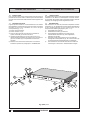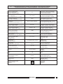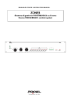
1
DAG9200
DAG9200/117
GENERATORE DIGITALE DI ALLARMI
DIGITAL ALARM GENERATOR
GENERATEUR NUMERIQUE D’ALARMES
DIGITALER ALARMGENERATOR
DIGITALE ALARMSIGNAALGENERATOR
GENERADOR DIGITAL DE ALARMAS
DIGITAL ALARM GENERATOR
SLOW
FAST SLOW
1-TONE
FAST SLOW
2-TONES
FAST DOWN
SIREN
SOMMARIO
1
1.1
1.2
1.3
1.4
1.5
1.6
1.7
2
2.1
2.2
2.3
2.4
3
3.1
3.2
3.3
3.4
3.5
4
5
DESCRIZIONE GENERALE
INTRODUZIONE __________________________________________
PANNELLO FRONTALE ______________________________________
PANNELLO POSTERIORE _____________________________________
L'APPARECCHIO __________________________________________
ALIMENTAZIONE E MESSA A TERRA ______________________________
INSTALLAZIONE __________________________________________
MONTAGGIO IN RACK ______________________________________
CONNESSIONI
GENERALITÁ ____________________________________________
INGRESSI PER LA REGISTRAZIONE ______________________________
TASTIERA ESTERNA _______________________________________
INTERFACCIA SERIALE ______________________________________
USO DELL'APPARECCHIO
CONFIGURAZIONE ________________________________________
REGOLAZIONI UTENTE ______________________________________
REGISTRAZIONE DEL MESSAGGIO ______________________________
RIPRODUZIONE ALLARMI E MESSAGGIO REGISTRATO __________________
PROTOCOLLO SERIALE _____________________________________
PARTI DI RICAMBIO ___________________________________
CARATTERISTICHE TECNICHE _________________________
DESCRIPTION GENERALE
INTRODUCTION __________________________________________
PANNEAU AVANT _________________________________________
PANNEAU ARRIERE ________________________________________
L’APPAREIL _____________________________________________
ALIMENTATION ET MISE A LA TERRE _____________________________
INSTALLATION ___________________________________________
MONTAGE SUR RACK ______________________________________
CONNEXIONS
GENERALITES ___________________________________________
ENTREES POUR L’ENREGISTREMENT _____________________________
CLAVIER EXTERIEUR _______________________________________
INTERFACE SERIELLE ______________________________________
UTILISATION DE L’APPAREIL
CONFIGURATION _________________________________________
REGLAGE UTILISATEUR _____________________________________
ENREGISTREMENT DU MESSAGE _______________________________
REPRODUCTION D’ALARMES ET MESSAGE ENREGISTRE ________________
PROTOCOLE SERIEL _______________________________________
LISTE DES PIÈCES DÉTACHÉES ________________________
CARACTÉRISTIQUE TECHNIQUES ______________________
2
2
2
3
3
4
4
5
5
6
6
7
7
8
8
9
26
27
ALGEMENE BESCHRIJVING
INLEIDING ______________________________________________
VOORPANEEL ___________________________________________
ACHTERPANEEL __________________________________________
HET APPARAAT __________________________________________
STROOMVOORZIENING EN AARDING _____________________________
INSTALLATIE ____________________________________________
MONTAGE IN REK _________________________________________
AANSLUITINGEN
ALGEMEEN _____________________________________________
INGANGEN VOOR HET OPNEMEN _______________________________
EXTERN TOETSENBORD _____________________________________
SERIELE INTERFACE _______________________________________
GEBRUIK VAN HET TOESTEL
CONFIGURATIE __________________________________________
GEBRUIKERSINSTELLINGEN ___________________________________
BERICHT OPNEMEN ________________________________________
WEERGAVE ALARMSIGNALEN EN OPGENOMEN BERICHT ________________
SERIEEL PROTOCOL _______________________________________
LIJST VAN ONDERDELEN ______________________________
TECHNISCHE KENMERKEN ____________________________
PLAY
REC.
POWER
1
1.1
1.2
1.3
1.4
1.5
1.6
1.7
2
2.1
2.2
2.3
2.4
3
3.1
3.2
3.3
3.4
3.5
4
5
GENERAL DESCRIPTION
INTRODUCTION __________________________________________
FRONT PANEL ___________________________________________
REAR PANEL ____________________________________________
THE APPARATUS _________________________________________
INSTALLATION ___________________________________________
POWER SUPPLY AND GROUNDING ______________________________
RACK MOUNTING _________________________________________
CONNECTIONS
GENERAL ______________________________________________
RECORDING INPUTS _______________________________________
EXTERNAL KEYBOARD ______________________________________
SERIAL INTERFACE ________________________________________
USING THE EQUIPMENT
CONFIGURATION _________________________________________
USER ADJUSTMENTS _______________________________________
RECORDING A MESSAGE ____________________________________
SOUNDING OF THE ALARMS AND RECORDED MESSAGE _________________
SERIAL PROTOCOL ________________________________________
SPARE PARTS _______________________________________
TECHNICAL CHARACTERISTICS ________________________
2
2
2
3
3
4
4
5
5
6
6
7
7
8
8
9
26
27
INHALTSVERZEICHNIS
10
10
10
11
11
12
12
13
13
14
14
15
15
16
16
17
26
27
KORTE INHOUDSOPGAVE
1
1.1
1.2
1.3
1.4
1.5
1.6
1.7
2
2.1
2.2
2.3
2.4
3
3.1
3.2
3.3
3.4
3.5
4
5
CONT.
TABLE OF CONTENTS
SOMMAIRE
1
1.1
1.2
1.3
1.4
1.5
1.6
1.7
2
2.1
2.2
2.3
2.4
3
3.1
3.2
3.3
3.4
3.5
4
5
UP
SLOW WHOOP
1
1.1
1.2
1.3
1.4
1.5
1.6
1.7
2
2.1
2.2
2.3
2.4
3
3.1
3.2
3.3
3.4
3.5
4
5
ALLGEMEINE BESCHREIBUNG
EINLEITUNG ____________________________________________
FRONTPANEEL ___________________________________________
RÜCKPANEEL ___________________________________________
GERÄTEBESCHREIBUNG _____________________________________
EINSPEISUNG UND ERDUNG __________________________________
INSTALLATION ___________________________________________
RACKMONTAGE __________________________________________
ANSCHLÜSSE
ALLGEMEINE HINWEISE _____________________________________
EINGÄNGE FÜR DIE TONAUFNAHME _____________________________
EXTERNE TASTATUR _______________________________________
SERIELLE SCHNITTSTELLE ___________________________________
GEBRAUCH DES GERÄTS
KONFIGURATION _________________________________________
INDIVIDUELLE EINSTELLUNG __________________________________
AUFNAHME VON MELDUNGEN _________________________________
WIEDERGABE VON ALARMEN UND AUFGENOMMENEN MELDUNGEN __________
SERIELLES PROTOKOLL _____________________________________
ERSATZTEILLISTE ____________________________________
TECHNISCHE EIGENSCHAFTEN ________________________
10
10
10
11
11
12
12
13
13
14
14
15
15
16
16
17
26
27
INDICE
18
18
18
19
19
20
20
21
21
22
22
23
23
24
24
25
26
27
1
1.1
1.2
1.3
1.4
1.5
1.6
1.7
2
2.1
2.2
2.3
2.4
3
3.1
3.2
3.3
3.4
3.5
4
5
DAG 9200
DESCRIPCIÓN GENERAL
INTRODUCCION __________________________________________
PANEL DELANTERO ________________________________________
PANEL TRASERO _________________________________________
EL APARADO ____________________________________________
ALIMENTACION Y PUESTA A TIERRA _____________________________
INSTALACION ____________________________________________
MONTAJE EN RACK ________________________________________
CONEXIONES
GENERALIDADES _________________________________________
ENTRADAS PARA LA GRABACION _______________________________
TECLADO EXTERNO _______________________________________
INTERFAZ SERIAL _________________________________________
EMPLEO DEL APARATO
CONFIGURACION _________________________________________
GRABACION DEL MENSAJE ___________________________________
REPRODUCCION ALARMAS Y MENSAJE GRABADO _____________________
AJUSTES USARIO _________________________________________
PROTOCOLO SERIAL _______________________________________
LISTA DE LAS PARTES DE RECAMBIO ___________________
CARACTERÍSTICAS TÉCNICAS _________________________
18
18
18
19
19
20
20
21
21
22
22
23
23
24
24
25
26
27
1
DESCRIZIONE GENERALE
GENERAL DESCRIPTION
1
1.1
INTRODUZIONE
Nel ringraziarVi per aver scelto un prodotto PASO, vogliamo
ricordarVi che la nostra azienda opera con sistema di qualità
certificato UNI EN ISO 9002. I nostri prodotti vengono pertanto
controllati in ogni fase della produzione per garantire la piena
soddisfazione del Vostro acquisto. Per ogni evenienza la garanzia
coprirà, nell’anno di validità, eventuali difetti di fabbricazione. Per
il corretto utilizzo di questo prodotto e per sfruttarne appieno le
prestazioni vi raccomandiamo di leggere e seguire attentamente
le istruzioni d’uso che seguono.
1.1
INTRODUCTION
In thanking you for your choice of a PASO product, we would like
to remind you that our company works with a quality system
certified according to UNI EN ISO 9002. Our products are therefore
checked in each phase of production in order to ensure that you
will be fully satisfied with your purchase. In any case the guarantee
will cover any manufacturing defects for the year of its validity. In
order to use this product correctly and to exploit its performance
in full, we recommend that you read and follow the instructions
given below carefully.
1.2
1.2
[1]
[2]
[3]
[4]
[5]
[6]
PANNELLO FRONTALE
[1]
[2]
[3]
[4]
[5]
[6]
- Display
- Tasti di esecuzione degli allarmi (dal n° 1 al n° 8)
- Tasto di esecuzione della nota fissa (allarme n°9)
- Tasto di esecuzione del messaggio registrato
- Interruttore a chiave per registrazione messaggio
- Interruttore di rete
FRONT PANEL
- Display
- Key for sounding the alarms (from n° 1 to n° 9)
- Key for sounding the steady tone (alarm n°9)
- Key for playing the recorded message
- Key switch for recording the message
- Mains switch
DIGITAL ALARM GENERATOR
SLOW
FAST
1-TONE
1.3
[7]
[8]
[9]
[10]
[11]
[12]
[13]
[14]
[15]
[16]
[17]
[18]
SLOW
FAST SLOW
2-TONES
FAST DOWN
SIREN
UP
SLOW WHOOP
CONT.
PANNELLO POSTERIORE
1.3
- Connessione di massa telaio
- Spina di rete
- Fusibile di rete
- Morsetti per il collegamento dell'alimentazione esterna
- Connettore per linea seriale
- Connettore per tastiera esterna
- Regolazione frequenza della nota fissa (allarme n°9)
- Regolazione del livello del segnale di uscita
- Presa per il segnale di uscita
- Presa di ingresso per segnali ad alto livello (AUX)
- Regolazione della sensibilita’ dell'ingresso AUX
- Presa d'ingresso microfonica
2
PLAY
[7]
[8]
[9]
[10]
[11]
[12]
[13]
[14]
[15]
[16]
[17]
[18]
DAG 9200
REC.
POWER
REAR PANEL
- Chassis ground connection
- Mains plug
- Mains fuse
- Terminals for connecting external power supply
- Serial line connector
- External keyboard connector
- Fixed tone frequency control (alarm n°9)
- Signal output level control
- Socket for output signal
- Input socket for high-level signals (AUX)
- AUX input sensitivity control AUX
- Microphone input socket
DESCRIZIONE GENERALE
GENERAL DESCRIPTION
1
1.4
L'APPARECCHIO
Il DAG9200 (DAG9200/117) è un generatore di segnali
d'allarme con la possibilità di registrare e riprodurre un
messaggio vocale. Gli allarmi generati sono nove di cui uno
rispondente alla normativa DIN33404 e uno personalizzabile
dall'utente. L'apparecchio può essere comandato
esternamente da una tastiera remota o da una macchina
master (via collegamento seriale RS232); l'alimentazione può
essere da rete o da apparato esterno in corrente continua a
24 V. I'uscita del generatore dispone di un'impedenza molto
bassa per pilotare più amplificatori in parallelo.
1.4
THE APPARATUS
The DAG9200 is a digital alarm signal generator providing the
possibility of recording and playing a voice message. The
number of alar ms generated is nine, of which one in
accordance with the DIN33404 standard and one which can
be customised by the user. The apparatus can be controlled
externally via a remote keyboard or from a master machine
(by means of an RS 232 serial link). It can be powered from
the mains supply or from an external 24 V DC power supply.
The output of the generator has a very low impedance level
so as to enable several parallel amplifiers to be driven.
1.5
ALIMENTAZIONE E MESSA A TERRA
L’apparecchio é predisposto per il funzionamento con tensione di
rete a 230 V ± 10% (117 V ± 10% per la versione DAG9200/117),
50/60 Hz. Il fusibile di rete è accessibile dal pannello posteriore
dell'apparecchio [9]. In alternativa, è previsto il funzionamento
con una tensione continua esterna di 24 V (± 10%) applicabile ai
relativi morsetti [10]. Un fusibile e un diodo, posti all'interno
dell'apparecchio, proteggono l'apparecchio contro i sovraccarichi
e le inversioni di polarità dell'alimentazione esterna in corrente
continua; a lato del portafusibile è riportato il relativo valore. In
accordo con le normative di sicurezza, l’interruttore di accensione
[6] agisce solo sulla tensione di rete.
L’apparecchio é corredato di cavo di alimentazione con
filo di messa a terra ed il relativo terminale sulla spina
d i r e t e n o n d ev e e s s e r e r i m o s s o i n a l c u n c a s o .
Assicurarsi che la presa di corrente sia dotata di
collegamento di terra a norme di legge.
1.5
POWER SUPPLY AND GROUNDING
The apparatus is designed to work with a direct voltage of 230 V
± 10% (117 V ± 10% for the DAG9200/117 version), 50/60 Hz.
The mains fuse is accessible from the rear panel of the apparatus
[9]. As an alternative, it can be run on an external direct voltage of
24 V (± 10%) applicable to the appropriate terminals [10]. A fuse
and a diode, located inside the apparatus, protect it from overloads
and polarity inversions of the external direct current power supply.
The correct rating of the fuse is indicated next to the fuse-holder.
In accordance with the safety regulations, the mains switch [6]
works only for the mains power supply.
The apparatus is supplied with a power cable equipped
with a ground wire. The corresponding terminal on the
mains plug must not be removed under any
circumstances. Make sure that the power outlet has a
ground connection in accordance with the law.
NOTE DI SICUREZZA
SAFETY NOTES
Ogni intervento all’interno dell’apparecchio, quale la
selezione di alcuni modi d’uso o la sostituzione di fusibili,
deve essere effettuato solo da personale specializzato:
Any activities inside the apparatus, such as the selection
of some operating modes or the replacement of fuses,
must be carried out solely by specialised personnel:
LA RIMOZIONE DEL COPERCHIO RENDE ACCESSIBILI PARTI CON
REMOVING THE COVER WILL EXPOSE PARTS WHICH CAN CAUSE
RISCHIO DI SCOSSE ELETTRICHE.
ELECTRIC SHOCKS.
Before removing the cover, always make sure that the
power cable is disconnected.
In the event of accidental spillage of liquids on the
apparatus, disconnect the mains plug immediately and
contact the nearest PASO Service Centre. The chassis
ground connection [7] makes it possible to connect other
equipment, solely for the purpose of shielding low-level
signals: this socket must not be used for the safety
connection of the chassis to earth.
PASO S.p.A. will not accept any liability for damages to
goods and/or persons due to failure to comply with the
above recommendations.
Prima di rimuovere il coperchio accertarsi sempre che il
cavo di rete sia staccato.
Nel caso di accidentale caduta di liquidi sull’apparecchio,
staccare immediatamente la spina di rete ed interpellare il
centro di assistenza PASO più vicino. La connessione di massa
telaio [7] consente di collegare altre apparecchiature per la
sola funzione di schermatura dei segnali a basso livello: questa
presa non deve essere utilizzata per il collegamento di
sicurezza del telaio alla terra.
La PASO S.p.A. declina ogni responsabilità in caso di
danni a cose e/o persone derivati dall’inosservanza delle
raccomandazioni sopra riportate.
DAG 9200
3
DESCRIZIONE GENERALE
GENERAL DESCRIPTION
1
1.6
INSTALLAZIONE
Per un corretto funzionamento dell’apparecchio evitare di
posizionarlo in prossimità di sorgenti di calore. Assicurarsi che
tutti gli ingressi e le uscite siano correttamente collegati prima
della accensione.
1.6
INSTALLATION
In order for the apparatus to work correctly, avoid placing it near
sources of heat. Make sure that all the inputs and outputs are
correctly connected before switching on.
1.7
MONTAGGIO IN RACK
L'apparecchio può essere montato in un rack standard a 19"
utilizzando l’apposito kit adattatore 27/2466 (opzionale). Di seguito
è riportata la procedura da seguire per il montaggio a rack e la
relativa illustrazione (fig. 1.7.1).
1) Rimuovere i piedini d'appoggio.
2) Togliere le due viti (A).
3) Fissare le due squadrette di sostegno (B) utilizzando le
quattro viti autofilettanti (C) fornite a corredo del kit.
4) Inserire l'apparecchio nel rack e fissarlo ad esso utilizzando
le due piastrine di copertura (D), le quattro viti (E) e le
relative rondelle (F) in dotazione.
5) Eseguire i collegamenti necessari seguendo le indicazioni
riportate nella sezione 2 “CONNESSIONI”.
1.7
RACK MOUNTING
The apparatus may be mounted in a 19” standard rack using the
special adaptor kit 27/2466 (optional). The procedure for rack
mounting is given below, together with an illustration (Figure 1.7.1).
1) Remove the feet.
2) Remove the two screws (A).
3) Secure the two supporting brackets (B) in place using the
four self-tapping screws (C) supplied with the kit.
4) Insert the apparatus inside the rack and secure it in place
using the two covering plates (D), the four screws (E) and
the relevant washers (F) supplied with the kit.
5) Make the appropriate connections following the instructions
given under point 2 “CONNECTIONS”.
C A
DIGITA
L ALAR
M GE
NERA
TOR
D
SLOW
FAST SLO
W FAS
1-TONE
T
2-TONES
SLOW
FAST DOW
N
UP
SIREN
SLOW WHO
OP
CONT.
B
E
PLAY
REC.
POWER
D
F
A B C
E
Fig. 1.7.1
4
DAG 9200
F
CONNESSIONI
2
CONNECTIONS
2.1
GENERALITÁ
Collegare la sorgente di alimentazione desiderata facendo
riferimento a quanto riportato al paragrafo 1.5. Collegare quindi il
generatore all'impianto di amplificazione utilizzando l'uscita OUT
[15]. In fig. 2.1.1 è riportato lo schema di collegamento alla presa
BASE-IN degli amplificatori PASO, questo collegamento consente
di attivare automaticamente l'ammutolimento degli ingressi AUX
(generalmente utilizzati per diffondere musica di sottofondo)
quando viene emesso un segnale di allarme.
2.1
GENERAL
Connect the desired source of power, referring to the information
given in point 1.5. Then connect the generator to the amplifying
system using the OUT output [15]. Fig. 2.1.1 shows the diagram
for connection to the BASE-IN socket of PASO amplifiers. This
connection can be used to activate muting of the AUX inputs
automatically (generally used to broadcast background music)
when an alarm signal is sounded.
2.2
INGRESSI PER LA REGISTRAZIONE
Per registrare un messaggio vocale nella memoria interna del
DAG9200 è necessario utilizzare un microfono di tipo dinamico
con uscita bilanciata (come ad esempio i modelli PASO M931,
M961-B, M965) collegato alla presa [18], il preamplificatore interno
provvederà, tramite un apposito circuito, alla regolazione
automatica del livello di registrazione. L'apparecchio dispone
inoltre di una presa a livello AUX [16] per la registrazione di
messaggi provenienti da mixer, riproduttori di nastri audio o
analoghi apparecchi; il livello di registrazione andrà
opportunamente dosato tramite il controllo [17]. In fig. 2.2.1 sono
riportate le connessioni a queste prese. NOTA: non è possibile
utilizzare contemporaneamente i due ingressi (AUX e MIC.) per
la registrazione di messaggi.
2.2
RECORDING INPUTS
To record a voice message in the internal memory of the DAG9200
it is necessary to use a dynamic microphone with a balanced
output (for example PASO M931, M961-B, M965 models)
connected to the socket [18]. The internal pre-amplifier will take
care, by means of a special circuit, of automatic adjustment of the
recording level. The apparatus also has an AUX level socket [16]
for recording messages originating from mixers, players of sound
tapes or other similar equipment. The recording level has to be
suitably metered by means of the appropriate control [17]. Figure
2.2.1 shows the connections to these sockets. NOTE: it is not
possible to use the two inputs (AUX and MIC.) at the same time
for recording messages.
1
3
5
4
2
Fig. 2.1.1
OUT AUX IN
MIC
1
1 : schermo / shield
2 : segnale (lato caldo) / signal (hot side)
2
3
1 : schermo / shield
2 : segnale (lato caldo) / signal (hot side)
3 : segnale (lato freddo) / signal (cold side)
1
2
Fig. 2.2.1
DAG 9200
5
CONNESSIONI
2
CONNECTIONS
2.3
TASTIERA ESTERNA
Il connettore maschio a 9 poli di tipo "D" [12] permette di collegare
una tastiera esterna per il comando a distanza dell’apparecchio.
Gli scambi di un rele’ oppure le transmission gates degli integrati
C-MOS (tipo CD4051/2/3) possono essere utilizzati per selezionare
e attivare gli allarmi da riprodurre. In tabella 2.3.1 sono riportate le
coppie di terminali da cortocircuitare per attivare gli allarmi; dalla
durata della chiusura dei contatti dipende la modalità di esecuzione
degli allarmi in modo identico a quanto descritto per il funzionamento
dell'apparecchio (vedi par. 3.3 e 3.4).
2.3
EXTERNAL KEYBOARD
The type "D" 9-pin male connector [12] can be used to connect an
external keyboard for remote control of the equipment. The contacts
of a relay or the transmission gates of the C-MOS integrated circuits
(type CD4051/2/3) can be used to select and activate the alarms to
be sounded. Table 2.3.1 shows the pairs of terminals to be shortcircuited in order to activate the alarms. The manner in which the
alarms are performed depends on the duration of the closure of the
contacts, in a manner identical to that described for operation of the
apparatus (see paragraphs 3.3 and 3.4).
2.4
INTERFACCIA SERIALE
Il connettore maschio a 9 poli di tipo "D" [11] consente di collegare
il DAG9200 ad altre apparecchiature che utilizzino lo standard di
comunicazione RS232. Tramite questa connessione è quindi
possibile comandare e configurare il generatore per mezzo di un
personal computer, una centralina d'allarme, ecc.. In fig. 2.4.1
sono riportati i collegamenti a questo connettore mentre il
protocollo di comunicazione è descritto dettagliatamente a pag. 9
(par. 3.5).
2.4
SERIAL INTERFACE
The type "D" 9-pin male connector [11] can be used to connect
the DAG9200 to other equipment which uses the RS 232
communications standard. It is therefore possible to control and
configure the generator via this connection using a personal
computer, a central alarm unit, etc. Figure 2.4.1 shows the
connections to this connector, while the communications protocol
is described in detail in paragraph 3.5 (pag. 9).
FUNZIONE
FUNCTION
TERMINALI
PINS
Allarme
Alarm
N°1
1
6
Allarme
Alarm
N°2
1
7
Allarme
Alarm
N°3
1
8
Allarme
Alarm
N°4
4
6
Allarme
Alarm
N°5
4
7
Allarme
Alarm
N°6
4
8
Allarme
Alarm
N°7
3
6
Allarme
Alarm
N°8
3
7
Allarme
Alarm
N°9
3
8
Esecuzione messaggio registrato
Recorded message play
2
6
Registrazione messaggio
Message recording
2
7
Esecuzione messaggio registrato
Recorded message play
2
8
5 = GND
2 = RX
3 = TX
Fig. 2.4.1
Tab. 2.3.1
6
DAG 9200
USO DELL'APPARECCHIO
3
USING THE EQUIPMENT
3.1
CONFIGURAZIONE
All'interno del DAG9200 sono presenti due ponticelli per impostare
la durata degli allarmi e l'abilitazione della tastiera dell'apparecchio.
La posizione dei ponticelli è rilevabile dalla fig. 3.1.1. Il ponticello
CN103 nella posizione "1" (impostazione di fabbrica) abilita sia la
tastiera interna che quella esterna, nella posizione "2" abilita la
sola tastiera esterna. Il ponticello CN104 in posizione "1"
(impostazione di fabbrica) imposta la durata della riproduzione
dell'allarme (o del messaggio registrato), una volta attivato, per
un tempo pari a un minuto; nella posizione "2" la riproduzione
dell'allarme (o del messaggio registrato) continuerà fino ad una
ulteriore selezione dello stesso. Queste impostazioni possono
anche essere modificate dall'esterno attraverso la comunicazione
seriale (vedi par. 2.4), tali modifiche avranno effetto temporaneo:
alla riaccensione dell'apparecchio risulteranno valide le
impostazioni determinate dai ponticelli interni.
3.1
CONFIGURATION
There are two jumpers inside the DAG9200 for setting the duration
of the alarms and for enabling the keyboard of the apparatus. The
positions of the jumpers can be seen in Figure 3.1.1. In position
"1" (factory setting) jumper CN103 enables both the internal and
the external keyboards. In position "2" it only enables the external
keyboard. In position "1" (factory setting) jumper CN104 sets the
length of time for which the alarm (or the recorded message) will
play to one minute once it has been activated . When the jumper
is in position "2" , the alarm (or the recorded message) will continue
to play until it is selected again. These settings can also be
changed from outside using the serial communications option (see
paragraph 2.4). These changes will have a temporary effect, and
when the apparatus is switched on again, the settings determined
by the internal jumpers will apply once again.
3.2
REGOLAZIONI UTENTE
Una volta collegato all'impianto di amplificazione è opportuno
adattare il livello d'uscita del generatore al resto della catena audio,
allo scopo occorre attivare la riproduzione di un allarme
(particolarmente utile può risultare la nota fissa dell'allarme n°9)
e intervenire sul controllo di livello [14]. Nel caso che il generatore
risulti collegato all'ingresso BASE AMPLIFICATA degli amplificatori
PASO si deve provvedere, dopo aver effettuato la regolazione
del livello di uscita del generatore, alla taratura del livello di soglia
della precedenza automatica di tale ingresso (A.P.T.). Queste
regolazioni, una volta effettuate, non devono essere più modificate.
Il controllo [13] permette di regolare la nota fissa dell'allarme n° 9
in un campo di frequenze comprese tra i 400 Hz e i 1000 Hz.
3.2
USER ADJUSTMENTS
Once it has been connected to the amplifying system, it is advisable
to adjust the output level of the generator to the rest of the audio
chain. To do this, it is necessary to activate reproduction of an alarm
(the steady tone of alarm n° 9 is particularly useful for this purpose)
and to adjust the level control [14]. If the generator is connected to
the AMPLIFIED BASE input of a PASO amplifier, after adjusting
the output level from the generator it is necessary to calibrate the
threshold level of the automatic precedence of this input (A.P.T.).
Once these adjustments have been made, the settings must not be
changed again.
Control [13] can be used to adjust the steady tone of alarm n° 9
within a frequency range comprised between 400 Hz and 1000 Hz.
Fig. 3.1.1
DAG 9200
7
USO DELL'APPARECCHIO
3
USING THE EQUIPMENT
3.3
REGISTRAZIONE DEL MESSAGGIO
Per effettuare la registrazione di un messaggio, utilizzando
l'ingresso microfonico o l'ingresso ausiliario (vedi par. 2.2),
l'apparecchio deve trovarsi in condizione di attesa (sul display [1]
sarà visualizzato un trattino orizzontale) e la chiave fornita in
dotazione all'apparecchio deve essere inserita nell'apposito
interruttore [5]. Ruotando la chiave di 90° in senso orario verrà
cancellato il contenuto corrente della memoria e attivata la nuova
registrazione, il display visualizzerà il simbolo . La registrazione
terminerà automaticamente dopo 58 sec. (±5%), il display
visualizzerà con un conteggio a ritroso l'approssimarsi
dell'esaurimento della memoria disponibile e con una "E" la fine
della registrazione. Al termine della registrazione, o per
interromperla anticipatamente (ad esempio alla fine di un
messaggio di pochi secondi), occorre riportare la chiave in
posizione verticale (sul display sarà visualizzato un trattino
orizzontale). Una volta conclusa la registrazione del messaggio è
buona norma provvedere subito al riascolto per verificare la buona
riuscita dell'operazione. Se il messaggio presenta un rumore di
fondo elevato occorre ripetere la registrazione avvicinando
maggiormente la bocca al microfono e/o parlare più forte (in caso
di registrazione dall'ingresso AUX [16] occorre aumentarne la
sensibilità ruotando l'apposito controllo [17] in senso orario); se il
messaggio risulta fortemente distorto occorre allontanare la bocca
dal microfono e/o parlare più piano (in caso di registrazione
dall'ingresso AUX [16] occorre ridurne la sensibilità ruotando
l'apposito controllo [17] in senso anti-orario). Il messaggio, una
volta registrato, è mantenuto in memoria per una durata illimitata
nel tempo anche in assenza di alimentazione.
3.3
RECORDING A MESSAGE
To record a message using the microphone input or the auxiliary
input (see paragraph 2.2), the apparatus must be on stand-by (a
horizontal dash will be visible on the display [1]) and the key
supplied with the apparatus must be inserted in its switch [5].
Turn the key by 90° in a clockwise direction to cancel the current
contents of the memory and to activate recording of the new
message. The symbol
will appear on the display. The recording
will end automatically after 58 seconds (±5%). A countdown will
appear on the display as the available storage space starts to run
out, while an "E" will indicate the end of the recording. Once the
recording has been completed, or to stop it before the time is up
(if the message lasts only a few seconds, for example), it is
necessary to return the key to a vertical position (a horizontal
dash will appear on the display). Once recording of the message
has been completed, it is a good rule to play it back immediately
to make sure that the operation was successful. If the message
has a high level of background noise, repeat the recording
procedure holding the microphone nearer to your mouth and/or
speaking more loudly (if the message was recorded via the AUX
input [16], it is necessary to increase its sensitivity by turning the
appropriate control knob [17] in a clockwise direction). If the
message is badly distorted, it is necessary to hold the microphone
further away from your mouth and/or to speak more quietly (if
recording using the AUX input [16], it is necessary to reduce its
sensitivity by turning the appropriate control knob [17] in an anticlockwise direction). Once the message has been recorded, it is
stored in the memory for an unlimited period of time, even in the
absence of power.
3.4
3.4
RIPRODUZIONE ALLARMI E MESSAGGIO
REGISTRATO
Il DAG9200 genera otto diversi tipi di allarme, selezionabili tramite
i tasti [2], più una nota fissa (tasto [3]) e un messaggio registrato
(tasto [4]). Per iniziare la riproduzione di un allarme, o del
messaggio registrato, occorre premere brevemente il relativo tasto,
il display visualizzerà il numero dell'allarme riprodotto o una "P"
se è stato selezionato il messaggio registrato. La riproduzione
terminerà in modo dipendente dalla configurazione
dell'apparecchio (vedi par. 3.1): dopo sessanta secondi se
l'apparecchio è impostato per un minuto di riproduzione, oppure,
se risulta impostata per la durata illimitata, dopo un'ulteriore
pressione del tasto relativo all'allarme (o messaggio) in
esecuzione. Si noti che, se è stato registrato un messaggio di
durata inferiore al minuto, esso verrà ripetuto più volte fino al
termine della riproduzione. Premendo e tenendo premuto (per
oltre due secondi) un tasto, l'allarme (o il messaggio) relativo verrà
riprodotto fino al rilascio del tasto stesso.
NOTA: le frequenze e la temporizzazione dell'allarme n° 7
rispondono alle prescrizioni della normativa DIN33404.
8
SOUNDING OF THE ALARMS AND RECORDED
MESSAGE
The DAG9200 generates eight different types of alarm, which can
be selected by means of keys [2], plus a steady tone (key [3]) and
a recorded message (key [4]). To start sounding an alarm, or
playing the recorded message, it is necessary to press the relevant
key briefly. The number of the alarm being sounded, or a "P" if the
recorded message has been selected, will appear on the display.
The alarm will stop sounding depending on how the apparatus
has been configured (see paragraph 3.1): after sixty seconds if
the apparatus has been set to sound for one minute or, if it has
been set on an unlimited duration, after pressing the key referring
to the alarm being sounded (or to the message) again. Note that
if the message recorded lasts less than one minute, it will be
repeated over and over again until the play time-out. If a key is
pressed and held down (for longer than two seconds) the alarm
(or the message) in question will be sounded (or played) until the
key is released.
NOTE: the frequencies and timing of alarm n° 7 correspond to
the requirements of DIN33404 standard.
DAG 9200
USO DELL'APPARECCHIO
3
3.5
PROTOCOLLO SERIALE
È possibile controllare il funzionamento del DAG9200, e
modificarne le impostazioni, con una apparecchiatura esterna
attraverso la porta di comunicazione seriale [11] con standard
RS232. La comunicazione tra i due apparati deve essere effettuata
con le seguenti impostazioni: VELOCITÀ 2400 BAUD, 8 BIT DI DATI, UN
BIT DI START E UNO DI STOP. Di seguito sono riportati i codici relativi
alle varie istruzioni.
USING THE EQUIPMENT
3.5
SERIAL PROTOCOL
It is possible to control operation of the DAG9200 and to change
its settings by means of an external apparatus, by means of the
RS232 standard serial communications port [11]. Communications
between the two pieces of equipment must be made with the
following settings: SPEED 2400 BAUDS, 8 DATA BITS, ONE START BIT AND
ONE STOP BIT. The codes referring to the various different instructions
are given below.
DATO RICEVUTO
RECEIVED DATA
DATO TRASMESSO
TRANSMITTED DATA
INTERROGAZIONE STATO MACCHINA
STATUS MACHINE REQUEST
NOTIFICA STATO MACCHINA
STATUS MACHINE NOTATION
0000 - attesa / stand-by
allarme (da 1 a 9)
0001 ÷ 1001 - esecuzione
alarm (from 1 to 9) playing
esecuzione messaggio registrato
1011 recorded message playing
1: tastiera interna abilitata / internal keyboard enabled
0: tastiera interna disabilitata / internal keyboard disabled
1: tempo di esecuzione 60 sec. / 60 sec. playing time
0: tempo di esecuzione illimitato / unlimited playing time
CONFIGURAZIONE
SETTING
ESEGUITO
AKNOLEDGE
1: tastiera interna abilitata / internal keyboard enabled
0: tastiera interna disabilitata / internal keyboard disabled
1: tempo di esecuzione 60 sec. / 60 sec. playing time
0: tempo di esecuzione illimitato / unlimited playing time
ESECUZIONE ALLARMI / MESSAGGIO
ALARM / MESSAGE PLAY
ESEGUITO
AKNOLEDGE
esecuzione allarme (da 1 a 9)
0000 ÷ 1000 play alarm (from 1 to 9)
1001
esecuzione messaggio registrato
play recorded message
AZZERAMENTO SISTEMA
SYSTEM RESET
QUALSIASI DATO NON RIPORTATO IN QUESTA TABELLA
ALL DATA NOT REPORTED IN THIS TABLE
ESEGUITO
AKNOLEDGE
NON INTERPRETABILE
NOT-AKNOLEDGE
DAG 9200
9
DESCRIPTION GENERALE
1
ALLGEMEINE BESCHREIBUNG
1.1
INTRODUCTION
Nous vous remercions d’avoir choisi un produit PASO et tenons
à vous rappeler que notre société adopte un système de qualité
certifié UNI EN ISO 9002. Nos produits sont donc contrôlés lors
de chaque phase de la production ce qui vous permettra d’être
pleinement satisfait de votre achat. Notre garantie vous protégera
en outre, pour l’année de validité, contre tout défaut de fabrication
éventuel. Pour l’utilisation correcte de ce produit et la pleine
exploitation de ses performances, nous vous invitons à lire et à
respecter scrupuleusement le mode d’emploi reporté ci-après.
1.1
EINLEITUNG
Wir danken Ihnen für die Wahl eines PASO-Produktes und
erinnern Sie daran, daß unsere Firma im Rahmen des
Qualitätssicherungssystems mit der Zertifizierung gemäß UNI EN
ISO 9002 arbeitet. Unsere Produkte werden dementsprechend
in jeder Produktionsphase kontrolliert, um die Zufriedenheit der
Kunden mit unseren Produkten zu gewährleisten. Die Garantie
deckt daher während des Garantiejahres eventuelle
Produktionsfehler ab. Zur Sicherstellung eines korrekten
Gebrauchs des Produktes und der vollen Nutzung aller
Funktionen, empfehlen wir, die folgende Bedienungsanleitung zu
lesen und den Anweisungen aufmerksam zu folgen.
1.2
1.2
PANNEAU AVANT
[1]
[2]
[3]
[4]
[5]
[6]
- Cadran d’affichage
- Touches d’exécution des alarmes (n°1 à n°8)
- Touche d’exécution de la note fixe (alarme n°9)
- Touche d’exécution du message enregistré
- Interrupteur à clé pour enregistrement message
- Interrupteur d’alimentation
[1]
[2]
[3]
[4]
[5]
[6]
FRONTPANEEL
- Display
- Tasten für die Alarmschaltungen (von Nr. 1 bis Nr. 8)
- Taste für die Schaltung des Grundtons (Alarm Nr. 9)
- Taste für die Schaltung der aufgenommenen Meldung
- Schlüsselschalter für die Aufnahme der Meldung
- Netzschalter
DIGITAL ALARM GENERATOR
SLOW
FAST
1-TONE
1.3
SLOW
FAST SLOW
2-TONES
FAST DOWN
SIREN
UP
SLOW WHOOP
CONT.
PANNEAU ARRIERE
[7]
[8]
[9]
[10]
[11]
[12]
[13]
[14]
[15]
[16]
[17]
[18]
1.3
- Connexion de mise à la masse
- Fiche d’alimentation
- Fusible de réseau
- Bornes pour le branchement de l’alimentation extérieure
- Connecteur pour ligne sérielle
- Connecteur pour clavier extérieur
- Réglage fréquence de la note fixe (alarme n°9)
- Réglage du niveau du signal de sortie
- Prise pour le signal de sortie
- Prise d’entrée pour signaux de haut niveau (AUX)
- Réglage de la sensibilité de l’entrée AUX
- Prise d’entrée microphonique
10
PLAY
[7]
[8]
[9]
[10]
[11]
[12]
[13]
[14]
[15]
[16]
[17]
[18]
DAG 9200
REC.
POWER
RÜCKPANEEL
- Erdschutzanschluß des Gehäuses
- Netzstecker
- Netzsicherung
- Anschlußklemmen für die externe Stromversorgung
- Verbinder für Reihenschaltung
- Verbinder für die externe Tastatur
- Frequenzregulierung des Grundtons (Alarm Nr. 9)
- Regulierung der Signalausgangsstufe
- Buchse für das Ausgabesignal
- Eingangsbuchse für Hochfrequenzsignale (AUX)
- Regulierung der Eingangsempfindlichkeit AUX
- Eingangsbuchse für das Mikrofon
DESCRIPTION GENERALE
1
ALLGEMEINE BESCHREIBUNG
1.4
L’APPAREIL
Le DAG9200 est un générateur numérique de signaux d’alarme
qui offre la possibilité d’enregistrer et de reproduire un
message vocal. Les alarmes générées sont au nombre de neuf
dont une répondant à la nor me DIN33404 et une
personnalisable par l’utilisateur. L’appareil peut être commandé
extérieurement par un clavier à distance ou par une machine
‘maître’ (par connexion série de type RS232); l’alimentation
peut être de réseau ou bien fournie par un appareil extérieur
fournissant un courant continu à 24 V. La sortie du générateur
dispose d’une impédance très basse afin de pouvoir piloter
plusieurs amplificateurs en parallèle.
1.4
GERÄTEBESCHREIBUNG
Das Gerät DAG9200 ist ein digitaler Alarmgenerator, der die
Möglichkeit bietet, Tonmeldungen aufzunehmen und
wiederzugeben. Es werden neun Alarmsignale erzeugt, von denen
ein Signal der Norm DIN33404 entspricht und ein weiteres vom
Benutzer selbst eingestellt werden kann. Das Gerät kann mit einer
Fernbedienungstastatur gesteuert werden oder aber von einem
Mastergerät (mittels seriellem RS232-Anschluß); die Einspeisung
kann sowohl mit Netzstrom als auch mit externer
Gleichstormversorgung mit 24 V erfolgen. Der Ausgang des
Generators besitzt eine sehr niedrige Impedanz, um mehrere
parallel geschaltete Verstärker steuern zu können.
1.5
ALIMENTATION ET MISE A LA TERRE
Cet appareil est prévu pour fonctionner avec une tension
d’alimentation à 230 V ±10% (117 V ±10% pour la version
DAG9200/117), 50/60 Hz. Le fusible de réseau est accessible
depuis le panneau arrière de l’appareil [9]. En alternative il est
prévu son fonctionnement avec une tension continue extérieure
à 24 V (± 10%) applicable aux bornes [10] prévues à cet effet. Le
fusible et la diode situés à l’intérieur de l’appareil protègent ce
dernier contre les surcharges et les inversions de polarité de
l’alimentation extérieure en courant continu; la valeur du fusible
est reportée à côté du porte-fusible. Conformément aux normes
de sécurité, l’interrupteur de mise en marche [6] n’agit que sur la
tension de réseau.
L’appareil est muni d’un câble d’alimentation avec fil de mise
à la terre et la borne d’entrée présente sur la fiche
d’alimentation ne doit être enlevée en aucun cas. S’assurer
que la prise de courant est munie d’une ligne de terre
conforme aux normes en vigueur.
1.5
EINSPEISUNG UND ERDUNG
Das Gerät ist für den Betrieb mit Netzstrom 230 V ±10% (117 V
±10% für die Version DAG9200/117), 50/60 Hz, konstruiert. Auf
die Netzsicherung hat man vom Rückpaneel [9] des Geräts Zugriff.
Alternativ hierzu kann das Gerät mit Gleichstrom bei 24 V (± 10%)
betrieben werden, der auf die entsprechenden Klemmen [10]
aufgebracht wird. Eine Sicherung und eine Diode im Innern des
Geräts schützen es vor Überstrom und Umkehrung der Polen bei
externer Einspeisung mit Gleichstrom; auf der Sicherung ist der
entsprechende
Wer t
angegeben.
Gemäß
den
Sicherheitsbestimmungen steuert der Hauptschalter [6] nur den
Netzstrom.
Das Gerät ist mit einem Einspeisungskabel mit Erdleiter
ausgestattet; das entsprechende Terminal am Netzstecker
darf daher auf keinen Fall entfernt werden. Sicherstellen, daß
der Netzstecker mit einem den Normen entsprechenden
Erdanschluß versehen ist.
MESURES DE SECURITE
SICHERHEITSHINWEISE
Toute intervention à l’intérieur de l’appareil, comme par
exemple la sélection de certains modes d’utilisation ou
la substitution des fusibles, doit être réalisée par un
personnel expert: LE RETRAIT DU COUVERCLE REND ACCESSIBLES
Jeder Eingriff in das Innere des Geräts, wie die Auswahl
von Betriebsar ten oder das Auswechseln von
Sicherungen darf nur von Fachpersonal durchgeführt
werden: DAS ENTFERNEN DES DECKELS LEGT TEILE FREI, BEI
DEREN BERÜHREN DIE GEFAHR ELEKTRISCHER SCHLÄGE BESTEHT.
Vor Entfernen des Deckels muß immer kontrolliert
werden, ob das Netzkabel abgenommen wurde.
Bei versehentlichem Kontakt des Geräts mit
Flüssigkeiten muß umgehend das Netzkabel entfernt und
die nächste Technische Kundendienststelle von PASO
informiert werden. Der Anschluß der Erdschutzleitung
am Gehäuse [7] erlaubt auch den Anschluß anderer
Geräte zum ausschließlichen Abschirmen von
Tieftonsignalen: der Anschluß darf nicht für die Erdung
des Gehäuses verwendet werden.
PASO S.p.A. haftet nicht für Schäden an Personen oder
Gegenständen infolge von Zuwiderhandlung der oben
angeführten Empfehlungen.
CERTAINS
COMPOSANTS
PRÉSENTANT
DES
RISQUES
D’ÉLECTROCUTION.
Avant d’enlever le couvercle, contrôler toujours que le
câble d’alimentation soit débranché.
En cas de chute accidentelle de liquides sur l’appareil,
débrancher immédiatement la fiche d’alimentation et
contacter le centre d’assistance PASO le plus proche.
La connexion de mise à la masse [7] permet de brancher
d’autres appareillages pour la seule fonction de
protection des signaux de bas niveau: cette prise ne doit
pas être utilisée pour le branchement de sécurité du
châssis à la terre.
PASO S.p.A. décline toute responsabilité en cas de
dommages aux choses et/ou aux personnes dus au nonrespect des conseils de sécurité précédemment cités.
DAG 9200
11
DESCRIPTION GENERALE
1
ALLGEMEINE BESCHREIBUNG
1.6
INSTALLATION
Pour un fonctionnement correct de l’appareil, éviter de le placer à
proximité de sources de chaleur. S’assurer que toutes les entrées
et sorties sont correctement reliées avant de mettre l’appareil sous
tension.
1.6
INSTALLATION
Zur Gewährleistung eines ordnungsgemäßen Betriebs, sollte die
Installation in der Nähe von Wärmequellen vermieden werden.
Vor Einstellen des Geräts sollte sichergestellt werden, daß alle
Eingänge und Ausgänge korrekt angeschlossen sind.
1.7
MONTAGE SUR RACK
L’appareil peut être monté sur un rack standard de 19" en utilisant
le kit adaptateur 27/2466 (optionnel) prévu à cet effet. Ci-après la
procédure à suivre pour l’installation sur rack et la figure
correspondante (fig. 1.7.1).
1) Enlever les pieds d’appui.
2) Enlever les deux vis (A).
3) Fixer les deux équerres de soutien (B) en utilisant les
quatre vis-tarauds (C) fournies avec le kit.
4) Introduire l’appareil dans le rack et le fixer à celui-ci en
utilisant les deux plaquettes de protection (D), les quatre vis
(E) et les rondelles (F) correspondantes fournies avec
l’appareil.
5) Effectuer les branchements nécessaires en suivant les
indications reportées au paragraphe 2 “CONNEXIONS”.
1.7
RACKMONTAGE
Das Gerät kann mit Hilfe des passenden Adapterkits 27/2466
(Optional) in ein 19" Standardrack montiert werden. Nachstehend
ist die Handlungsabfolge für die Rackmontage und die
entsprechende Abbildung angegeben (Abb. 1.7.1).
1)
Die Stellfüßchen entfernen.
2)
Die Beiden Schrauben (A) entfernen.
3)
Die Stützbügel (B) befestigen und hierfür die vier
selbstwindenen Schrauben (C) des mitgelieferten
Einbaukits verwenden.
4)
Das Gerät in das Rack einsetzen und es mit Hilfe der
beiliegenden Abdeckplättchen (D), der vier Schrauben (E)
mit entsprechenden Unterlegscheiben (F) befestigen.
5)
Die erforderlichen Anschlüsse herstellen und hierfür die
Anweisungen in Abschnitt 2 “ANSCHLÜSSE” befolgen.
C A
DIGITA
L ALAR
M GE
NERA
TOR
D
SLOW
FAST SLO
W FAS
1-TONE
T
2-TONES
SLOW
FAST DOW
N
UP
SIREN
SLOW WHO
OP
CONT.
PLAY
B
E
REC.
POWER
D
F
A B C
E
Fig. (Abb.) 1.7.1
12
DAG 9200
F
CONNEXIONS
2
ANSCHLÜSSE
2.1
GENERALITES
Brancher la source d’alimentation désirée en se rapportant à ce
qui est indiqué au paragraphe 1.5. Brancher ensuite le générateur
à l’installation d’amplification en utilisant la sortie OUT [15]. La
fig. 2.1.1. reporte le schéma de branchement à la prise BASE-IN
des amplificateurs PASO; ce branchement permet de rendre
automatiquement silencieuses les entrées AUX (généralement
utilisées pour diffuser de la musique de fond) lorsqu’il est émis un
signal d’alarme.
2.1
ALLGEMEINE HINWEISE
Die gewünschte Einspeisung gemäß den Angaben in Abschnitt
1.5 anschließen. Danach den Generator über den Ausgang OUT
[15] an die Verstärkeranlage anschließen. Die Abbildung 2.1.1
zeigt das Anschlußschema für die Buchse BASE-IN an die PASO
Verstärker; dieser Anschluß ermöglicht die automatische
Betätigung der Muting-Funktion
der AUX-Eingänge
(normalerweise zur Wiedergabe von untermalender Musik
verwendet) wenn ein Alarmsignal erzeugt wird.
2.2
ENTREES POUR L’ENREGISTREMENT
Pour enregistrer un message vocal dans la mémoire interne du
DAG9200, il est nécessaire d’utiliser un microphone de type
dynamique à sortie équilibrée (comme par exemple les modèles
PASO M931, M961-B, M965) et de le brancher à la prise [18]; le
préamplificateur interne s’occupera, par le biais d’un circuit ad
hoc , du réglage automatique du niveau d’enregistrement.
L’appareil dispose en outre d’une prise au niveau AUX [16] pour
l’enregistrement de messages provenant de mixeurs, reproducteurs
de cassettes audio ou autres appareils semblables; le niveau
d’enregistrement sera réglée de façon appropriée par le dispositif
de contrôle [17]. La figure 2.2.1 reporte les connexions à ces prises.
N.B.: il n’est pas possible d’utiliser simultanément les deux entrées
(AUX et MIC.) pour l’enregistrement de messages.
2.2
EINGÄNGE FÜR DIE TONAUFNAHME
Für die Aufnahme von Tonmeldungen im internen Speicher des
DAG9200 muß ein dynamisches Mikrofon mit Symetrieausgang
verwendet (beispielsweise die Modelle von PASO M931, M961-B,
M965) und an die Buchse [18] angeschlossen werden; der
Vorverstärker im Innern des Geräts stellt die Aufnahmestufe mit
Hilfe einer entsprechenden Schaltung automatisch ein. Das Gerät
verfügt außerdem über eine AUX-Buchse [16] für die Aufnahme
von Meldungen des Mixers, Tonbandwiedegabegeräten oder
ähnlichen Geräten; die Aufnahmestufe muß mit Hilfe der
Kontrollfunktion [17] eingestellt werden. Die Abbildung 2.2.1 zeigt
die Anschlüsse an diese Buchsen. BEACHTE: es ist nicht möglich,
die beiden Eingänge (AUX und MIC.) gleichzeitig für die Aufnahme
von Meldungen zu verwenden.
1
3
5
4
2
Fig. 2.1.1
OUT AUX IN
MIC
1
1 : ecran / schirm
2 : signal (côté chaud) / signal (warme Seite)
2
3
1 : ecran / schirm
2 : signal (côté chaud) / signal (warme Seite)
3 : signal (côté froid) / signal (kalteSeite)
1
2
Fig. 2.2.1
DAG 9200
13
CONNEXIONS
2
ANSCHLÜSSE
2.3
CLAVIER EXTERIEUR
Le connecteur mâle à 9 broches de type “D” [12] permet
de brancher un clavier extérieur pour la commande à
distance de l’appareil. Les contacts d’un relais ou bien les
transmission gates des circuits intégrés C-MOS (type
CD4051/2/3) peuvent être utilisés pour sélectionner et
activer les alarmes à reproduire; de la durée de fermeture
des contacts dépend la modalité d’exécution des alarmes
comme cela est décrit pour le fonctionnement de l’appareil
(voir paragraphes 3.3 et 3.4).
2.3
EXTERNE TASTATUR
Der 9-polige Stecker vom Typ “D” [12] ermöglicht den Anschluß
einer externen Tastatur für die Fernbedienung des Geräts. Für
die Auswahl und Schaltung der wiederzugebenden
Alarmmeldungen können die Relaiskontakte oder die transmission
gates der integrierten C-MOS (Typ CD4051/2/3) verwendet
werden. Die Tabelle 2.3.1 zeigt die kurzzuschließenden Terminale
zur Schaltung der Alarme; die Art und Weise der Aufnahme der
Alarmsignale analog zu der oben beschriebenen Schaltung der
Alarme für den Betrieb des Geräts hängt von der Dauer der
Schließung der Kontakte ab (siehe Abschnitt 3.3 und 3.4).
2.4
INTERFACE SERIELLE
Le connecteur mâle à 9 broches de type “D” [11] permet de
brancher le DAG9200 à d’autres appareils qui utilisent le standard
de communication RS232. Cette connexion permet en outre de
commander et de configurer le générateur à l’aide d’un microordinateur, d’une centrale d’alarme, etc. La fig. 2.4.1 reporte les
branchements à ce connecteur alors que le protocole de
communication est décrit de façon détaillée au paragraphe 3.5.
2.4
SERIELLE SCHNITTSTELLE
Der 9-polige Stecker vom Typ “D” [11] ermöglicht den Anschluß
eines Geräts DAG9200 an andere Geräte, die den
Kommunikationsstandard RS232 verwenden. Mit Hilfe dieses
Anschlusses ist es daher möglich, den Generator mit einem
Computer, einer Alarmzentrale, usw., zu steuern und zu
konfigurieren. Die Abbildung 2.4.1 zeigt die Anschlüsse an diesen
Verbinder, während das Kommunikationsprotokoll detailliert in
Abschnitt 3.5 beschriebenen ist.
FONCTION
FUNKTION
BORNES
TERMINALE
Alarme
Alarmwiedergabe
N°1
1
6
Alarme
Alarmwiedergabe
N°2
1
7
Alarme
Alarmwiedergabe
N°3
1
8
Alarme
Alarmwiedergabe
N°4
4
6
Alarme
Alarmwiedergabe
N°5
4
7
Alarme
Alarmwiedergabe
N°6
4
8
Alarme
Alarmwiedergabe
N°7
3
6
Alarme
Alarmwiedergabe
N°8
3
7
Alarme
Alarmwiedergabe
N°9
3
8
2
6
2
7
2
8
Exécution message enregistré
Wiedergabe der aufgenommenen Meldung
Enregistrement du message
Aufnahme Von Meldungen
Exécution message enregistré
Wiedergabe der aufgenommenen Meldung
5 = GND
2 = RX
3 = TX
Fig. 2.4.1
Tab. 2.3.1
14
DAG 9200
UTILISATION DE L’APPAREIL
GEBRAUCH DES GERÄTS
3
3.1
CONFIGURATION
Les deux pontets présents à l’intérieur du DAG9200 servent
à sélectionner la durée des alarmes et l’habilitation du
clavier de l’appareil. La position des pontets est indiquée
à la fig. 3.1.1. En position “1” le pontet CN103 (valeur
d’usine) habilite aussi bien le clavier interne qu’externe et
en position “2” il habilite seulement le clavier extérieur. En
position “1” (valeur d’usine) le pontet CN104 sélectionne
la durée de reproduction de l’alarme (ou du message
enregistré), après son activation, pour une durée égale à
une minute; en position “2” la reproduction de l’alarme (ou
du message enregistré) continuera jusqu’à une ultérieure
sélection de celui-ci. Ces sélections peuvent également
être modifiées par l’extérieur par l’intermédiaire de la
c o m m u n i c a t i o n s e r i e l l e ( vo i r p a r a g r a p h e 2 . 4 ) ; c e s
m o d i f i c a t i o n s a u r o n t t o u t e fo i s s e u l e m e n t u n e f fe t
temporaire et, lors du réallumage de l’appareil, les valeurs
adoptées seront celles sélectionnées par les pontets
internes.
3.1
KONFIGURATION
Im Innern des DAG9200 sind zwei Überbrückungsklemmen für
die Einstellung der Dauer des Alarms sowie für Aktivierung der
Tastatur des Geräts vorhanden. Die Positionierung der
Überbrückungsklemmen kann der Abbildung 3.1.1. entnommen
werden. Die Überbrückungsklemme CN103 in der Position “1”
(werkseitige Einstellung) aktiviert sowohl die interne als auch die
externe Tastatur, in der Position “2” aktiviert sie nur die externe
Tastatur. Die Überbrückungsklemme CN104 in Position “1”
(werkseitige Einstellung) reguliert die Dauer der Alarmwiedergabe
(oder der Wiedergabe der aufgenommen Meldung), wenn sie
aktiviert wird, für eine Dauer von einer Minute; in der Position “2”
wird die Wiedergabe der Alarmmeldung (oder der Wiedergabe
der aufgenommen Meldung) bis zur erneuten Betätigung
fortgesetzt. Diese Voreinstellungen können auch von außen mit
Hilfe der seriellen Kommunikation geändert werden (siehe
Abschnitt 2.4). Die Modifizierungen sind in ihrer Dauer begrenzt:
bei erneutem Einschalten des Geräts werden die Einstellungen
der Überbrückungsklemmen im Innern des Geräts verwendet.
3.2
REGLAGE UTILISATEUR
Une fois branché à l’installation d’amplification il est opportun
d’adapter le niveau de sortie du générateur au reste de la chaîne
audio; activer à cette fin la reproduction d’une alarme (la note
d’alarme n°9 peut dans ce cas s’avérer fort utile) et intervenir sur
le contrôle de niveau [14]. Si le générateur est branché à l’entrée
BASE AMPLIFIEE des amplificateurs PASO procéder, après avoir
effectué le réglage du niveau de sortie du générateur, au réglage
du niveau de seuil de la priorité automatique (A.P.T.) de cette
entrée. Une fois effectués, ces réglages ne doivent plus être
modifiés.
Le contrôle [13] permet de régler la note fixe de l’alarme n° 9
dans un champ de fréquence compris entre 400 Hz et 1000 Hz.
3.2
INDIVIDUELLE EINSTELLUNG
Nach Anschluß der Verstärkeranlage sollte die Ausgangsstufe
des Generators an die Einstellung der gesamtenTonanlage
angepaßt werden. Zu diesem Zweck muß die Wiedergabe eines
Alarms eingeschaltet (günstig hierfür könnte der Grundton des
Alarms Nr. 9 sein) und die Stufenkontrolle [14] aktiviert werden.
Falls der Generator am Eingang VERSTÄRKTE BASIS von PASO
Verstärkern angeschlossen ist, muß nach Regulierung der
Ausgangsstufe des Generators die Eichung des Schwellenwertes
des automatischen Vortritts dieses Eingangs (A.P.T.) erfolgen.
Die Regulierungen dürfen später nicht mehr verstellt werden.
Die Kontrolle [13] ermöglicht die Regulierung des Grundtons des
Alarms Nr. 9 in einem Frequenzbereich von 400 Hz bis 1000 Hz.
Fig. 3.1.1
DAG 9200
15
UTILISATION DE L’APPAREIL
GEBRAUCH DES GERÄTS
3
3.3
ENREGISTREMENT DU MESSAGE
Pour effectuer l’enregistrement d’un message, en utilisant l’entrée
microphonique ou l’entrée auxiliaire (voir par. 2.2), l’appareil doit
se trouver en état d’attente (le cadran d’affichage [1] affichera un
petit trait horizontal) et la clé fournie avec l’appareil doit être
introduite dans l’interrupteur [5] correspondant. En tournant la
clé de 90° dans le sens des aiguilles d’une montre, le contenu
courant de la mémoire sera supprimé et le nouvel enregistrement
sera activé, le cadran d’affichage reportera le symbole .
L’enregistrement s’interrompra automatiquement après 58
secondes (±5%), le cadran d’affichage indiquera à l’aide d’un
compte à rebours le temps de mémoire restant et avec la lettre
“E” la fin de l’enregistrement. A la fin de l’enregistrement, ou pour
l’arrêter à l’avance (par exemple après un message de quelques
secondes seulement), il suffit de placer la clé en position verticale
(le cadran d’affichage reportera un petit trait horizontal). Une fois
conclu l’enregistrement du message, il est conseillé de l’écouter
tout de suite après afin de contrôler que l’opération s’est bien
déroulée. Si le message présente un bruit de fond élevé, il est
nécessaire de répéter l’enregistrement en approchant davantage
la bouche du microphone et/ou de parler plus fort (en cas
d’enregistrement en utilisant l’entrée AUX [16] il est nécessaire
d’en augmenter la sensibilité en tournant le bouton de contrôle
[17] correspondant dans le sens des aiguilles d’une montre); si le
message est fortement brouillé, éloigner la bouche du microphone
et/ou parler moins fort (en cas d’enregistrement en utilisant l’entrée
AUX [16] il est nécessaire de diminuer la sensibilité en tournant
le bouton de contrôle [17] correspondant dans le sens contraire
aux aiguilles d’une montre). Une fois enregistré, le message est
mémorisé pour une durée illimitée et ce également en cas
d’absence d’alimentation.
3.3
AUFNAHME VON MELDUNGEN
Für die Aufnahme einer Meldung wird der Mikrofoneingang oder
der Hilfseingang verwendet (siehe Abschnitt 2.2); das Gerät muß
auf Wartestellung geschaltet sein (auf dem Display [1] wird ein
horizontaler Strich angezeigt) und der mitgelieferte Schlüssel muß
in den entsprechenden Schalter [5] eingesetzt werden. Durch
Drehen des Schlüssels um 90° im Uhrzeigersinn wird der z.Z. im
Speicher vorhandene Inhalt gelöscht und die Aufnahmefunktion
für eine neue Meldung aktviert. Das Display zeigt das Symbol@@
an. Die Aufnahme wird automatisch nach 58 Sekunden (±5%)
beendet. Das Display zeigt durch Rückzählen der Sekunden, die
bis zur Erschöpfung des Speichers noch verbleibende Zeit und
zeigt mit einem “E” das Ende der Aufnahme an. Bei Beendigung
der Aufnahme oder bei vorzeitiger Unterbrechung (beispielsweise
am Ende einer Meldung von wenigen Sekunden) muß der
Schlüssel in seine Grundposition zurückgebracht werden (auf dem
Display erscheint ein horizontaler Strich). Nach Beendigung der
Aufnahme sollte die Meldung abgehört werden, um das Ergebnis
zu kontrollieren. Falls die Meldung starke Untergrundgeräusche
zeigt, sollte die Aufnahme wiederholt und das Mikrofon näher am
Mund gehalten oder aber lauter gesprochen werden (bei
Aufnahme über den AUX Eingang [16] muss die Empfindlichkeit
durch Drehen des Kontrollknopfes [17] im Uhrzeigersinn verstärkt
werden); wenn die Meldung sehr verzerrt ist, muß der Sprecher
das Mikrofon weiter vom Mund entfernt halten bzw. langsamer
sprechen (bei Aufnahme über den AUX Eingang [16] muß die
Empfindlichkeit durch Drehen des entsprechenden
Kontrollknopfes [17] entgegengestzt dem Uhrzeigersinn reduziert
werden). Nach Aufnahme bleibt die Meldung über einen
unbegrenzten Zeitraum auch bei Trennung des Geräts von der
Stromversorgung im Speicher erhalten.
3.4
3.4
REPRODUCTION D’ALARMES ET MESSAGE
ENREGISTRE
Le DAG9200 a huit différents types d’alarme, sélectionnables à
l’aide des touches [2], plus une note fixe (touche [3]) et un message
enregistré (touche [4]). Pour commencer la reproduction d’une
alarme, ou du message enregistré, appuyer brièvement sur la
touche correspondante: le cadran affichera le numéro de l’alarme
reproduite ou la lettre “ P ” si le message enregistré a été
sélectionné. L’arrêt de la reproduction dépend de la configuration
de l’appareil (voir paragraphe 3.1): arrêt après 60 secondes si
l’appareil est réglé pour une minute de reproduction, ou bien, s’il
est réglé pour une durée illimitée, arrêt après une ultérieure
pression de la touche correspondant à l’alarme (ou message) en
cours d’exécution. A noter que, s’il a été enregistré un message
de durée inférieure à une minute, celui-ci sera répété plusieurs
fois jusqu’à la fin de la reproduction. En tenant appuyée une touche
pour plus de deux secondes, l’alarme (ou le message)
correspondant sera reproduit jusqu’à ce que la touche soit
relâchée.
N.B.: les fréquences et la temporisation de l’alarme n°7 sont
conformes aux prescriptions de la norme DIN33404.
16
WIEDERGABE VON ALARMEN UND
AUFGENOMMENEN MELDUNGEN
Das Gerät DAG9200 erzeugt acht verschiedene Alarme, die mit
Hilfe der Tasten [2] und einem Grundton (Taste [3]) sowie einer
aufgenommenen Meldung wiedergegeben werden können (Taste
[4]). Für die Wiedergabe eines Alarms oder einer aufgenommenen
Meldung muß die entsprechende Taste kurz gedrückt werden.
Das Display zeigt die Nummer des gewünschten Alarms an oder
aber ein “P”, wenn eine aufgenommene Meldung abgespielt
werden soll. Die Wiedergabe endet entsprechend der Einstellung
des Geräts (s. Abschnitt 3.1): nach 60 Sekunden, wenn das Gerät
auf die Dauer von einer Minute gestellt wurde oder, wenn eine
unbegrenzte Dauer eingestellt wurde, nach erneutem Drücken
des entsprechenden Alarmknopfes (oder der Meldung). Es muß
beachtet werden, daß Meldungen mit einer Dauer von weniger
als einer Minute mehrmals bis zum Ende der Wiedergabezeit
widederholt werden. Durch Drücken und Halten des Drucks einer
Taste (für mehr als zwei Sekunden), wird der Alarm (oder die
Meldung) abgespielt bis die Taste losgelassen wird.
BEACHTE: Die Frequenz und die zeitliche Programmierung des
Alarms Nr. 7 entsprechen den Vorschriften der Norm DIN33404.
DAG 9200
UTILISATION DE L’APPAREIL
GEBRAUCH DES GERÄTS
3
3.5
PROTOCOLE SERIEL
Il est possible de contrôler le fonctionnement du DAG9200, et
d’en modifier les sélections, à l’aide d’un appareil extérieur par
l’intermédiaire du port de communication série [11] de type RS232.
La communication entre les deux appareils doit être effectuée en
respectant les réglages suivants: 2.400 BAUDS, 8 BITS DE DONNÉES,
UN BIT DE MARCHE ET UN BIT D’ARRÊT. Il est reporté ci-après les codes
correspondant aux diverses instructions.
3.5
SERIELLES PROTOKOLL
Es ist möglich, den Betrieb des DAG9200 mit einem externen
Gerät über den seriellen Kommunikationsausgang [11] zu
kontrollieren und die Voreinstellungen mit Standard RS232 zu
verändern. Die Kommunikation zwischen den beiden Geräten muß
mit den folgenden Parametern erfolgen: GESCHWINDIGKEIT 2400
BAUD, 8 BIT FÜR DATEN, EIN BIT FÜR DEN START UND EIN BIT FÜR DEN
S TOP . Im folgenden werden die Codes für die einzelnen
Anweisungen angegeben.
DONNEE RECUE
DATEN ERHALTEN
DONNEE TRANSMISE
DATEN ÜBERTRAGEN
INTERROGATION ETAT MACHINE
ABFRAGE DES GERÄTEZUSTANDS
NOTIFICATION ETAT MACHINE
ANGABE DES GERÄTEZUSTANDS
0000 - attente / Warten
alarme (de 1 à 9)
0001 ÷ 1001 - exécution
Alarmwiedergabe (von 1 bis 9)
exécution message enregistré
1011 Wiedergabe der aufgenommenen Meldung
1: clavier interne habilité / Interne Tastatur aktiviert
0: clavier interne déshabilité / Interne Tastatur disaktiviert
1: temps d’exécution 60 sec / Aufnahmezeit 60 sec.
0: temps d’exécution illimité / Aufnahmezeit unbegrenzt
CONFIGURATION
KONFIGURATION
EXECUTE
DURCHGEFÜHRT
1: clavier interne habilité / Interne Tastatur aktiviert
0: clavier interne déshabilité / Interne Tastatur disaktiviert
1: temps d’exécution 60 sec / Aufnahmezeit 60 sec.
0: temps d’exécution illimité / Aufnahmezeit unbegrenzt
ESECUZIONE ALLARMI / MESSAGGIO
ALARM / MESSAGE PLAY
EXECUTE
DURCHGEFÜHRT
alarme (de 1 à 9)
0000 ÷ 1000 exécution
Alarmwiedergabe (von 1 bis 9)
1001
exécution message enregistré
Wiedergabe der aufgenommenen Meldung
ZEROTAGE SYSTEME
NULLUNG DES SYSTEMS
TOUTE DONNEE NON REPORTEE DANS CE TABLEAU
JEDE NICHT IN DIESER TABELLE ENTHALTENE ANGABE
EXECUTE
DURCHGEFÜHRT
NON RECONNU
NICHT VERWERTBAR
DAG 9200
17
ALGEMENE BESCHRIJVING
1
DESCRIPCIÓN GENERAL
1.1
INLEIDING
Wij danken u voor uw keuze van een PASO product en herinneren
u eraan dat de productie van ons bedrijf volgens een gecertificeerd
kwaliteitssysteem UNI EN ISO 9002 plaatsvindt. Onze producten
worden daarom in iedere productiefase gecontroleerd zodat u
zeker tevreden zult zijn met uw aankoop. Eventuele fabrieksfoutjes
zijn in het jaar dat de garantie geldig is, gedekt. Voor een goed
gebruik van dit product en voor een volledige benutting van de
prestaties hiervan, raden wij u aan onderstaande
gebruiksvoorschriften met aandacht door te lezen.
1.1
INTRODUCCIÓN
Agradeciéndoles por haber escogido un producto PASO, tengan
a bien recordárse que nuestra empresa obra con sistema de
calidad certificado UNI EN ISO 9002. Por lo tanto, nuestros
productos están controlados en todas sus fases de producción
para garantizar que el cliente compre un producto de máxima
satisfacción. Por toda eventualidad, la garantía cubrirá, en el año
de validez, posibles defectos de fabricación. Para un correcto
empleo de este producto y para aprovechar al máximo sus
prestaciones les recomendamos leer y seguir detenidamente las
instrucciones de empleo que se detallan a continuación.
1.2
1.2
VOORPANEEL
[1]
[2]
[3]
[4]
[5]
[6]
- Display
- Alarmsignaaltoetsen (van 1 t/m 8)
- Vastetoontoets (alarmsignaal 9)
- Afspeeltoets opgenomen bericht
- Sleutelschakelaar voor opname bericht
- Elektriciteitsschakelaar
[1]
[2]
[3]
[4]
[5]
[6]
PANEL DELANTERO
- Display
- Teclas reproducción de alarmas (de la n° 1 a la n° 8)
- Tecla reproducción de la nota fija (alarma n°9)
- Tecla reproducción del mensaje grabado
- Interruptor de llave para grabación mensaje
- Interruptor de red
DIGITAL ALARM GENERATOR
SLOW
FAST
1-TONE
1.3
SLOW
FAST SLOW
2-TONES
FAST DOWN
SIREN
UP
SLOW WHOOP
CONT.
ACHTERPANEEL
[7]
[8]
[9]
[10]
[11]
[12]
[13]
[14]
[15]
[16]
[17]
[18]
1.3
- Aardeverbinding frame
- Elektriciteitsstekker
- Netzekering
- Klemmen voor verbinding externe stroomvoorziening
- Verbindingsstekker seriële lijn
- Verbindingsstekker voor extern toetsenbord
- Instelling frequentie vaste toon (alarmsignaal 9)
- Instelling niveau uitgangssignaal
- Contactpunt voor uitgangssignaal
- Contactpunt ingang voor hoogniveausignalen (AUX)
- Instelling gevoeligheid bij ingang AUX
- Contactpunt microfooningang
18
PLAY
[7]
[8]
[9]
[10]
[11]
[12]
[13]
[14]
[15]
[16]
[17]
[18]
DAG 9200
REC.
POWER
PANEL TRASERO
- Conexión de masa bastidor
- Enchufe para red
- Fusible de red
- Bornes para la conexión con la alimentación externa
- Conector para línea serial
- Conector para teclado externo
- Ajuste frecuencia de la nota fija (allarme n°9)
- Ajuste del nivel de la señal de salida
- Toma para la señal de salida
- Toma de entrada para la señales de alto nivel (AUX)
- Ajuste de la sensibilidad de entrada AUX
- Toma de entrada microfónica
ALGEMENE BESCHRIJVING
1
DESCRIPCIÓN GENERAL
1.4
HET APPARAAT
DAG9200 is een digitale alarmsignaalgenerator waarmee een
ingesproken bericht opgenomen en weergegeven kan worden.
Er worden negen alarmsignalen voortgebracht, één beantwoordt
aan de DIN33404 norm en één kan door de gebruiker aan de
eigen behoefte aangepast worden. Het apparaat wordt extern
bestuurd door een op afstand bediend toetsenbord of
mastermachine (via seriële RS232 verbinding); de stroomtoevoer
kan geleverd worden door het elektriciteitsnet of door een extern
apparaat met 24V gelijkstroom. De generatoruitgang beschikt over
een zeer lage impedantie voor de parallele besturing van om
meerdere versterkers.
1.4
EL APARATO
DAG9200 es un generador digital de señales de alarma que posee
la posibilidad de grabar y reproducir un mensaje vocal. Las
alarmas generadas son nueve de las cuales una responde a la
norma DIN33404 y otra puede ser personalizada por el usuario.
El aparato puede ser gobernado por un teclado remoto o bien
por una máquina master (mediante conexión serial RS232); la
alimentación puede ser por red o por aparato externo de corriente
continua de 24 V. La salida del generador está provista de una
impedancia muy baja que sirve para gestir varios amplificadores
en paralelo.
1.5
STROOMVOORZIENING EN AARDING
Het apparaat is ingesteld voor werking bij een netspanning
van 230 V ±10% (117 V ±10% voor de versie DAG9200/117),
50/60 Hz. De netzeker ing is toegankelijk vanuit het
achterpaneel van het apparaat.[9]. Het apparaat kan ook
werken met een externe 24V gelijkstroomspanning (± 10%)
die aangebracht kan worden op de desbetreffende klemmen
[10]. Een zekering en een diode binnenin het apparaat geven
bescherming tegen overbelasting en polariteitsinversie van de
externe gelijkstroomvoorziening; de desbetreffende waarde is
naast de zekeringendoos aangegeven. Overeenkomstig de
veiligheidsvoorschriften werkt de aan/uitschakelaar [6] alleen
op netspanning.
Het apparaat is uitgerust met een elektriciteitssnoer met
aardingsdraad waarvan de bijbehorende eindklem in geen
geval verwijderd worden. Verzeker u ervan dat het
stroomcontactpunt voorzien is van de wettelijk
voorgeschreven aardeverbinding.
1.5
ALIMENTACIÓN Y PUESTA A TIERRA
El aparato ha sido creado para funcionar con una tensión de red
de 230 V ±10% (117 V ±10% para la versíon DAG9200/117),
50/60 Hz. El fusible de red es accesible desde el panel trasero
del aparato [9]. Como alternativa, es posible, también, hacerlo
funcionar con una tensión continua externa de 24 V (± 10%) que
puede ser aplicada a los relativos bornes [10]. Un fusibile y un
diodo, colocados dentro del aparato, protegen dicho aparato
contra las sobrecargas y contra las inversiones de polaridad de
la alimentación externa de corriente continua; al lado del
portafúsible está indicado el relativo valor. De acuerdo con las
normas de seguridad, el interrumptor de encendido [6] funciona
solamente con la tensión de red.
El aparato está dotado de cable de alimentación con hilo de
puesta a tierra y el relativo terminal en el enchufe de red no
debe ser quitado por ningún motivo. Cerciorárse que la toma
de corriente esté provista de conexión a tierra según los
requisitos de ley.
OPMERKINGEN BETREFFENDE DE VEILIGHEID
NOTAS de SEGURIDAD
Ingrepen aan de binnenkant van het apparaat, zoals
de selectie van verschillende gebruiksmodes of
vervanging van zekeringen, mag uitsluitend verricht
worden door gespecialiseerd personeel: INDIEN HET
DEKSEL VERWIJDERD IS , BESTAAT ER BIJ AANRAKING VAN DE
TOEGANKELIJKE DELEN GEVAAR OP ELEKTRISCHE SCHOKKEN .
Verzeker u er altijd van dat het elektriciteitssnoer
losgekoppeld is alvorens het deksel te verwijderen.
Indien er per ongeluk vloeistoffen op het apparaat
terechtkomen,
moet
onmiddellijk
de
elektr iciteitsstekker verwijderd worden en het
dichtstbijzijnde PASO servicecentrum geraadpleegd
worden. De frame-aardeverbinding [ 7] maakt
verbinding met andere apparatuur alleen mogelijk voor
de beveiligingsfunctie van laagniveausignalen: dit
contactpunt mag niet gebruikt worden voor de
veiligheidsverbinding tussen frame en aarde.
PASO S.p.A. wijst iedere aansprakelijkheid af voor
schade aan dingen en/of personen voortkomend uit
nietinachtneming van de hierbovenver melde
aanbevelingen.
To d a o p e r a c i ó n d e n t r o d e l a p a ra t o, c o m o l a
selección de algunos modos de empleo y la
s u s t i t u c i ó n d e f u s i bl e s, d e b e s e r e fe c t u a d a
solamente por personal especializado: QUITAR LA
TAPA PERMITE ACCEDER A LAS PARTES CON RIESGO DE
SACUDIDAS ELÉCTRICAS .
Antes de quitar dicha tapa cerciorarse siempre
que el cable de conexión con la red esté
desenchufado.
Por la eventualidad de la caída de líquidos sobre
e l a p a r a t o, d e s e n c h u fa r l o i n m e d i a t a m e n t e
desconectándolo de la red y contactar el centro
de asistencia PASO más cercano. La conexión de
masa bastidor [7] permite conectar otros aparatos
para la específica función de blindaje de las
señales de bajo nivel: esta toma no debe ser
utilizada para la conexión de seguridad del bastidor
a la tierra.
PASO S.p.A. no reconoce responsabilidad en caso
de daños a cosas y/o personas derivados por la
inobservancia de las recomedaciones detalladas.
DAG 9200
19
ALGEMENE BESCHRIJVING
1
DESCRIPCIÓN GENERAL
1.6
INSTALLATIE
Voor een goede werking van het apparaat wordt aangeraden het
apparaat niet in de nabijheid van warmtebronnen te plaatsen.
Verzeker u ervan dat alle ingangen en uitgangen op de goede
wijze verbonden zijn alvorens het apparaat in werking te stellen.
1.6
INSTALACIÓN
Para un correcto funcionamiento del aparato evitar su
posicionamiento cerca de fuentes de calor. Cerciorarse que todas
las entradas y las salidas se encuentren bien conectadas antes
de encender.
1.7
MONTAGE IN REK
Het apparaat kan in een standaardrek van 19" gemonteerd worden
met behulp van de speciale adapterkit 27/2466 (op verzoek).
Hieronder vindt u de procedure die u moet volgen voor de montage
in rek en bijbehorende illustratie (fig. 1.7.1).
1) Verwijder de steunpoten.
2) Verwijder de twee schroeven (A).
3) Bevestig de twee steunplaatjes (B) met behulp van de vier
bijgeleverde plaatschroeven (C).
4) Plaats het apparaat in het rek en zet het vast met behulp
van de twee dekplaatjes (D), de vier schroeven (E) en
bijbehorende en bijgeleverde borgschijfjes (F) .
5) Voer de nodige verbindingen uit volgens de in hoofdstuk 2
“AANSLUITINGEN” vermelde aanwijzingen.
1.7
MONTAJE EN RACK
El aparato puede ser montado en un rack standard de 19",
empleando la apropiada caja de montaje 27/2466 (facultativa).
A continuación se detalla el procedimiento a seguir para el
montaje en el rack y la relativa ilustración (fig. 1.7.1).
1) Quitar los pies de apoyo.
2) Extraer los dos tornillos (A).
3) Fijar los dos angulares de apoyo (B) utilizando los cuatro
tornillos autorroscantes (C) suministrados con la caja de
montaje
4) Introducir el aparato en el rack y fijarlo a él utilizando las
dos chapetas de cubierta (D), los cuatro tornillos (D), y las
cuatro arandelas presentes en el equipamiento base.
5) Efectuar las conexiones necesarias siguiendo las
indicaciones detalladas en la sección 2 “CONEXIONES”.
C A
DIGITA
L ALAR
M GE
NERA
TOR
D
SLOW
FAST SLO
W FAS
1-TONE
T
2-TONES
SLOW
FAST DOW
N
UP
SIREN
SLOW WHO
OP
CONT.
B
E
PLAY
REC.
POWER
D
F
A B C
E
Fig. 1.7.1
20
DAG 9200
F
AANSLUITINGEN
2
CONEXIONES
2.1
ALGEMEEN
Verbind de gewenste voedingsbron aan de hand van de
aanwijzingen van punt 1.5. Verbind de generator vervolgens met
de versterkingsinstallatie met gebruik van uitgang OUT [15]. Op
fig. 2.1.1 ziet u het verbindingsschema bij het BASE-IN contactpunt
van de PASO verstekers. Met deze verbinding kunt u automatisch
het geluiddempen van de AUX ingangen activeren (dit wordt
meestal gebruikt voor het uitzenden van achtergrondmuziek)
wanneer een alarmsignaal afgegeven wordt.
2.1
GENERALIDADES
Conectar la fuente de alimentación deseada usando como
referencia cuanto ilustrado en el párrafo 1.5. Luego conectar el
generador a la instalación de amplificación utilizando la salida
OUT [15]. En la fig. 2.1.1 se detalla el esquema de conexión con
la toma BASE-IN de los amplificadores PASO, esta conexión
permite habilitar automáticamente la función silenciamiento de
las entradas AUX (por lo general utilizadas para difundir música
de fondo) cuando se emite una señal de alarma.
2.2
INGANGEN VOOR HET OPNEMEN
Om een ingesproken bericht op te nemen in het interne geheugen
van de DAG9200 moet een dynamische microfoon gebruikt
worden met symmetrische uitgang (zoals de modellen PASO
M931, M961-B, M965 bijvoorbeeld) aangesloten op het
contactpunt [18]. De interne voorversterker zorgt via een speciaal
circuit voor de automatische instelling van het opnameniveau.
Het apparaat beschikt bovendien over een niveaucontactpunt AUX
[16] voor het opnemen van berichten afkomstig van mixers,
geluidsbanden of dergelijke apparaten; het opnameniveau wordt
via bedieningsknop [17] goed gedoseerd. In fig. 2.2.1 zijn de
verbindingen met deze contactpunten aangegeven. OPMERKING:
de twee ingangen (AUX en MIC.) kunnen niet tegelijkertijd gebruikt
worden voor het opnemen van berichten.
2.2
ENTRADAS PARA LA GRABACIÓN
Para grabar un mensaje vocal en la memoria interna de DAG9200
es necesario emplear un micrófono de tipo dinámico con salida
balanceada (como por ejemplo los modelos PASO M931, M961B, M965) conectado a la toma [18]; el preamplificador interno se
encargará, mediante un apropiado circuito, del ajuste automático
del nivel de grabación. Además el aparato está provisto de una
toma de nivel AUX [16] para la grabación de mensajes que
provienen de mixer, de reproductores de cintas audio o de
aparatos similares; el nivel de grabación puede ser
convenientemente ajustado por medio del control [17]. En la fig.
2.2.1 se detallan las conexiones con estas tomas. NOTA: no es
posible utilizar simultáneamente las dos entradas (AUX e MIC.)
para la grabación de mensajes.
1
3
5
4
2
Fig. 2.1.1
OUT
MIC
AUX IN
1
1 : scherm / pantalla
2 : signaal (warme kant) / señal (lado caliente)
2
3
1 : scherm / pantalla
2 : signaal (warme kant) / señal (lado caliente)
3 : signaal (koude kant) / señal (lado frío)
1
2
Fig. 2.2.1
DAG 9200
21
AANSLUITINGEN
2
CONEXIONES
2.3
EXTERN TOETSENBORD
Met behulp van de 9-polige steekstekker van het type “D” [12]
kan een extern toetsenbord aangesloten worden om het apparaat
op afstand te bedienen. De contacten van een relais of
transmission gates van de geïntegreerde C-MOS (type CD4051/
2/3) kunnen gebruikt worden om de weer te geven alarmsignalen
te selecteren en te activeren. In tabel 2.3.1 zijn de te kortsluiten
eindklemmen aangegeven om de alarmsignalen te activeren; van
de sluitingstijd van de sluitcontacten hangt de wijze van uitvoering
van de alarmsignalen af, op dezelfde wijze als hierboven
beschreven is betreffende de werking van het apparaat (zie punt
3.3 en 3.4).
2.3
TECLADO EXTERNO
El conector macho de 9 polos de tipo “D” [12] permite la conexión
de un teclado externo para el mando a distancia del aparato. Los
contactos de un relé o bien las transmission gates de los
integrados C-MOS (tipo CD4051/2/3) pueden ser empleados para
seleccionar y habilitar las alarmas a reproducir. En la tabla 2.3.1
se detallan las copias de terminales a cortocircuitar para habilitar
las alarmas; de la duración del cierre de los contactos depende
la modalidad de reproducción de las alarmas en modo idéntico a
cuanto descripto para el funcionamiento del aparato (ver párr.
3.3 y 3.4).
2.4
SERIELE INTERFACE
De 9-polige steekstekker van het type “D” [11] maakt het mogelijk
de DAG9200 te verbinden met andere apparatuur die gebruik
maakt van communicatiestandaard RS232. Via deze aansluiting
kunt u de generator vervolgens besturen en configureren met
behulp van een personal computer, een alarmregeleenheid enz..
In fig. 2.4.1 zijn de verbindingen met deze verbindingsstekker
aangegeven terwijl het communicatieprotocol uitvoerig
beschreven wordt bij punt 3.5.
2.4
INTERFAZ SERIAL
El conector macho de 9 polos de tipo “D” [11] permite conectar
DAG9200 con otros equipos que empleen el standard de
comunicación RS232. Por lo tanto, mediante esta conexión es
posible gobernar y configurar el generador por medio de un
personal computer, una central de alarma, etc.. En la fig. 2.4.1 se
detallan las conexiones con este conector, en vez, el protocolo
de comunicación se ilustra detalladamente en el párr. 3.5.
FUNCTIE
FUNCION
PINS
TERMINALES
Alarmsignaal
Alarma
N°1
1
6
Alarmsignaal
Alarma
N°2
1
7
Alarmsignaal
Alarma
N°3
1
8
Alarmsignaal
Alarma
N°4
4
6
Alarmsignaal
Alarma
N°5
4
7
Alarmsignaal
Alarma
N°6
4
8
Alarmsignaal
Alarma
N°7
3
6
Alarmsignaal
Alarma
N°8
3
7
Alarmsignaal
Alarma
N°9
3
8
Afspelen opgenomen bericht
Reproducción mensaje grabado
2
6
Bericht opnemen
Grabación del mensaje
2
7
Afspelen opgenomen bericht
Reproducción mensaje grabado
2
8
5 = GND
2 = RX
3 = TX
Fig. 2.4.1
Tab. 2.3.1
22
DAG 9200
3
GEBRUIK VAN HET TOESTEL
EMPLEO DEL APARATO
3.1
CONFIGURATIE
In de DAG9200 zijn twee brugverbindingen aanwezig om de
tijdsduur van de alarmsignalen in te stellen en het toetsenbord
van het apparaat in werking te stellen. De positie van de
brugverbindingen ziet u in fig. 3.1.1. De brugverbinding CN103 in
positie “1” (fabrieksinstelling) activeert zowel het interne als externe
toetsenbord, in positie “2” is alleen het externe toetsenbord
geactiveerd. De brugverbinding CN104 in positie “1”
(fabrieksinstelling) stelt de weergaveduur in van het geactiveerde
alarmsignaal (of van het opgenomen bericht) op één minuut; in
positie “2” gaat de weergave van het alarmsignaal (of van de
opgenomen bericht) door tot er een nadere selectie plaatsvindt.
Deze instellingen kunnen ook extern gewijzigd worden via de
seriële communicatie (zie punt 2.4). Deze wijzigingen zijn tijdelijk:
zodra het apparaat opnieuw aangezet wordt, blijken de door de
interne brugverbindingen bepaalde instellingen geldig.
3.1
CONFIGURACIÓN
Dentro de DAG9200 se encuentran dos puentes que sirven para
prefijar la duración de las alarmas y la habilitación del teclado del
aparato. La posición de lod puentes está detallada en la fig. 3.1.1.
El puente CN103 en la posición “1” (prefijada en fábrica) habilita
tanto el teclado interno como el externo, en la posición “2” se
habilita solamente el teclado externo. El puente CN104 en la
posición “1” (prefijada en fábrica) determina la duración de la
reproducción de la alarma (o del mensaje grabado), una vez
habilitada, por un tiempo equivalente a 1 minuto; en la posición
“2” la reproducción de la alarma (o del mensaje grabado)
continuará hasta que se efectúe una ulterior selección de dicha
alarma. Además, estas configuraciones pueden ser modificadas
desde el externo mediante la comunicación serial (ver párr. 2.4),
dichas modificaciones durarán por un determinado tiempo: cuando
se vuelva a encender el aparato resultarán válidas las
configuraciones determinadas por los puentes internos.
3.2
GEBRUIKERSINSTELLINGEN
Na aansluiting van de versterkingsinstellatie verdient het
aanbeveling het uitgangsniveau van de generator aan te passen
aan de rest van de geluidsketen. Hiertoe moet de weergave van
een alarmsignaal geactiveerd worden (vooral de vaste toon van
alarmsignaal 9 kan nuttig zijn) en de niveaubedieningsknop [14]
draaien. Indien de generator verbonden blijkt met de ingang van
de VERSTERKTE BASIS van de PASO versterkers moet na de
instelling van het generatoruitgangsniveau het drempelniveau van
de automatische voorrang van deze ingang (A.P.T.) geijkt worden.
Deze instellingen mogen, eenmaal verricht, niet meer gewijzigd
worden.
Met bedieningsorgaan [13] kan de vaste toon van alarmsignaal 9
ingesteld worden in een frequentieveld tussen de 400 Hz en 1000 Hz.
3.2
AJUSTES USARIO
Una vez conectada la instalación de amplificación es
conveniente ajustar el nivel de salida del generador al resto
de la cadena audio. Por tal motivo es necesario habilitar la
reproducción de una alarma (particulamente útil puede ser la
nota fija de la alarma n°9) y entonces accionar el control de
nivel [14]. En el caso en que el generador esté conectado con
la entrada BASE AMPLIFICADA de los amplificadores PASO,
se debe efectuar, después de haber realizado los ajustes del
nivel de salida del generador, el ajuste del umbral de la
prioridad automática de dicha entrada (A.P.T.). Estos ajustes,
una vez efectuados, no deben ser más modificados.
El control [13] permite ajustar la nota fija de la alarma n° 9 en
un campo de frecuencias entre los 400 Hz y los 1000 Hz.
Fig. 3.1.1
DAG 9200
23
EMPLEO DEL APARATO
3
GEBRUIK VAN HET TOESTEL
3.3
BERICHT OPNEMEN
Om een bericht op te nemen met gebruik van de microfooningang
of hulpingang (zie punt 2.2), moet het apparaat op wachten
staan (op het display [1] ziet u een horizontaal streepje) en de
bij het apparaat geleverde sleutek in de speciale schakelaar [5]
gestoken zijn. Indien u de sleutel 90° naar rechts draait, wordt
de actuele inhoud van het geheugen uitgewist en de nieuwe
opname geactiveerd. Op het display ziet u het teken
. De
opname eindigt automatisch na 58 sec. (±5%), op het display
ziet u via een aftelling het naderende einde van het beschikbare
geheugen en een “E” geeft het einde van de opname aan. Aan
het einde van de opname of om deze voortijdig te beëindigen
(bijvoorbeeld aan het eind van een slechts enkele seconden
durende bericht), moet de sleutel in verticale stand gezet worden
(op het display ziet u een horizontaal streepje). Na beëindiging
van de opname van het bericht is het beter deze meteen opnieuw
te beluisteren zodat u zeker weet dat de opname tot een goed
einde gebracht is. Indien het bericht een hard achtergrondgeluid
heeft, moet u de opname herhalen en de microfoon dichterbij de
mond houden en/of harder spreken (indien u bij de ingang AUX
[16] opneemt, moet u de gevoeligheid verhogen door de daarvoor
bestemde bedieningsknop [17] naar rechts te draaien); indien
het bericht sterk vervormd is, moet u de microfoon verder van
de mond houden en/of zachter spreken (indien u bij de ingang
AUX [16] opneemt, moet u de gevoeligheid verlagen door de
daarvoor bestemde bedieningsknop [17] naar links te draaien).
Het opgenomen bericht blijft voor onbepaalde tijd in het geheugen
opgeslagen, ook indien er geen stroomvoorziening is.
3.3
GRABACIÓN DEL MENSAJE
Para efectuar la grabación de un mensaje, utilizando la entrada
microfónica o la entrada auxiliar (ver párr. 2.2), el aparato debe
encontrarse en condición de espera (sobre el display [1] será
visualizada una rayita horizontal) y la llave suministrada junto con
el aparato debe ser introducida en el correspondiente interruptor
[5]. Girando la llave de 90° en sentido horario se cancelará el
contenido corriente de la memoria y se habilitará una nueva
grabación, el display visualizará el símbolo . La grabación finalizará
automáticamente después de 58 seg. (±5%), el display visualizará,
con una cuenta hacia atrás, cuando se aproxima el agotamiento
de la memoria disponible y con una “E” indicará el fin de la grabación.
Al concluir la grabación o bien si se interrumpe anticipadamente
(por ejemplo cuando concluye un mensaje de pocos minutos) es
necesario colocar de nuevo la llave en la posición vertical (sobre el
display será visualizada una rayita horizontal). Una vez terminada
la grabación del mensaje es buena norma escuchar cuanto grabado
para verificar que la operación haya sido efectuada con éxito. Si el
mensaje presenta un ruido de fondo elevado, es necesario repetir
la operación de grabación, acercando mucho más la boca al
micrófono y/o hablar más alto (en caso de grabación desde la
entrada AUX [16] ocurre aumentar la sensibilidad girando el
correspondiente control [17] en sentido horario); si el mensaje
resultante es muy distorcionado es necesario alejar la boca del
micrófono y/o hablar más despacio (en caso de grabación desde la
entrada AUX [16] es necesario reducir su sensibilidad girando el
correspondiente control [17] en sentido antihorario). El mensaje,
una vez grabado, se mantiene en memoria por una duración ilimitada
en el tiempo y sin la alimentación de corriente.
3.4
3.4
WEERGAVE ALARMSIGNALEN EN OPGENOMEN
BERICHT
DAG9200 genereert acht verschillende soorten alarmsignalen die
geselecteerd kunnen worden met behulp van de toetsen [2], plus
een vaste toon (toets [3]) en een opgenomen bericht (toets [4]).
Om de weergave van een alarmsignaal of een opgenomen bericht
te kunnen beginnen, moet de desbetreffende toets kortstondig
ingedrukt worden. Op het display ziet u het nummer van het
weergegeven alarmsignaal of een “P” indien het opgenomen bericht
gekozen is. De weergave eindigt op een wijze die afhankelijk is van
de configuratie van het apparaat (zie punt 3.1): na zestig seconden
indien het apparaat op één minuut is ingesteld of, indien het apparaat
voor onbepaalde tijd ingesteld blijkt, na opnieuw indrukken van de
toets die overeenkomt met het alarmsignaal (of bericht) dat men
aan het afspelen is. Uw aandacht wordt gevestigd op het feit dat
indien een bericht met een tijdsduur van meer dan een minuut is
opgenomen, deze meerdere keren herhaald wordt tot aan het einde
van de weergave. Indien u een toets indrukt en (langer dan twee
seconden) ingedrukt houdt, wordt het desbetreffende alarmsignaal
(of bericht) weergegeven totdat u de toets loslaat.
OPMERKING: de frequentie en tijdsduurinstelling van alarmsignaal
7 beantwoorden aan de voorschriften van de norm DIN33404.
24
REPRODUCCIÓN ALARMAS Y MENSAJE
GRABADO
DAG9200 genera ochos distintos tipos de alar mas,
seleccionables por medio de las teclas [2], más una nota fija
(tecla [3]) y un mensaje grabado (tecla [4]). Para iniciar con la
reproducción de una alarma, o bien del mensaje grabado, es
necesario presionar brevemente la correspondiente tecla, el
display visualizará el número de alarma reproducido o una
“ P ” si ha sido seleccionado el mensaje grabado. La
reproducción finalizará independientemente de como ha sido
prefijado el aparato (ver párr. 3.1): despúes de 60 segundos
si el aparato ha sido prefijado por un minuto de reproducción,
o bien, si resulta prefijada por una duración ilimitada, después
de una ulterior presión de la tecla relativa a las alarmas
(mensaje). Es importante notar que si ha sido grabado un
mensaje de duración inferior de un minuto éste se repetirá
varias veces hasta que concluya la reproducción. Presionando
y manteniendo presionada (por más de dos segundos) una
tecla, la alarma (o el mensaje) se reproduce hasta que se
suelte dicha tecla.
NOTA: las frecuencias y la temporización de la la alarma n° 7
responden a los requisitos de la norma DIN33404.
DAG 9200
GEBRUIK VAN HET TOESTEL
3
3.5
SERIEEL PROTOCOL
De werking van DAG9200, kan gecontroleerd worden en de
instellingen daarvan gewijzigd met behulp van externe apparatuur
door de seriële communicatiepoort [11] met standaard RS232.
De communicatie tussen de twee apparaten moet met de volgende
instellingen tot stand gebracht worden: SNELHEID 2400 BAUD, 8
GEGEVENSBITS, ÉÉN STARTBIT EN ÉÉN STOPBIT. Hieronder zijn de met de
diverse instructies overeenkomende codenummers aangegeven.
EMPLEO DEL APARATO
3.5
PROTOCOLO SERIAL
Es possibile controlar el funcionamiento de DAG9200, y modificar
cuanto prefijado, con un equipo externo mediante la puerta de
comunicación serial [11] con standard RS232. La comunicación
entre dos aparatos debe ser efectuada prefijando lo siguiente:
VELOCIDAD 2400 BAUD, 8 BITS DE DATOS, UN BIT DE ARRANQUE Y UNO DE
PARADA. A continuación se detallan los códigos relativos a las
distintas instrucciones.
ONTVANGEN GEGEVEN
DATO RECIBIDO
TRANSMITTED DATA
DATO TRASMITIDO
ONDERVRAGING STATUS MACHINE
INTERROGACIÓN ESTADO MÁQUINA
BERICHT STATUS MACHINE
INDICACIÓN DEL ESTATO MÁQUINA
0000 - wachten / espera
alarmsignaal (1 - 9)
0001 ÷ 1001 - afspelen
reproducción alarma (de 1 a 9)
afspelen opgenomen bericht
1011 reproducción mensaje grabado
1: intern toetsenbord geactiveerd / teclado interno habilitado
0: intern toetsenbord gedisactiveerd / teclado interno deshabilitado
1: afspeeltijd 60 sec. / tiempo de reproducción 60 seg.
0: afspeeltijd onbeperkt / tiempo de reproducción ilimitado
CONFIGURATIE
CONFIGURACIÓN
AFGESPEELD
REPRODUCIDO
1: intern toetsenbord geactiveerd / teclado interno habilitado
0: intern toetsenbord gedisactiveerd / teclado interno deshabilitado
1: afspeeltijd 60 sec. / tiempo de reproducción 60 seg.
0: afspeeltijd onbeperkt / tiempo de reproducción ilimitado
AFSPELEN ALARMSIGNALEN / BERICHT
REPRODUCCIÓN ALARMAS / MENSAJE
AFGESPEELD
REPRODUCIDO
0000 ÷ 1000
afspelen alarmsignaal (1 - 9)
reproducción alarma (de 1 a 9)
1001
afspelen opgenomen bericht
reproducción mensaje grabado
NULSTELLING SYSTEEM
AJUSTE DEL CERO SISTEMA
IEDER NIET IN DEZE TABEL VERMELD GEGEVEN
ALL DATA NOT REPORTED IN THIS TABLE
AFGESPEELD
REPRODUCIDO
NIET INTERPRETEERBAAR
NO INTERPRETABLE
DAG 9200
25
4
PARTI DI RICAMBIO - SPARE PARTS - LISTE DES PIÈCES DÉTACHÉES
ERSATZTEILLISTE - LIJST VAN ONDERDELEN - LISTA DE LAS PARTES DE RECAMBIO
DESCRIZIONE
NAME
DESCRIPTION
BESCHREIBUNG
BESCHRIJVING
DESCRIPCIÓN
COD.
Coperchio
Cover
Couvercle
Deckel
Deksel
Tapa
Pannello frontale
serigrafato
Silk screen printed
front pann.
Panneu avant
sérigraphié
Frontpaneel mit
Siebdruck
Zeefdrukkvoorpaneel
Panel delantero
serigrafado
Interruttore di
alimentazione
Mains switch
Interrupteur
d'alimentation
Netzschalter
Schakelaar
stroomvoorziening
Interruptor de
alimentación
Cond. di sicurezza
(2,2nF 250V)
Safety capacitor
(2,2nF 250V)
Condensateur de
sécurité
(2,2nF 250V)
Sicherheitskondensator
(2,2nF 250V)
Veiligheidscondensator
Condensador de
seguridad
Interruttore con
chiave
Key switch
Interrupteur à clé
Gesamte
Displayschaltung
Schakelaar met
sleutel
Interruptor con
llave
25/135
Spina di rete
Mains plug
Fiche réseau de
panneau
Netzstecker
Netstekker
Enchufe de red
25/83
Portafusibile
(corpo)
Fuse-holder (body)
Porte-fusible
(corps)
Sicherungsträger
(Einheit)
Zekeringendoos
(huis)
Portafusible
(cuerpo)
24/47
Portafusibile
(tappo)
Fuse-holder (plug)
Porte-fusible
(couvercle)
Sicherungsträger
(Verschluß)
Zekeringendoos
(dop)
Portafusible
(tapón)
24/48
Presa microfonica
XLR
XLR microphone
socket
Prise
microphonique
XLR
Mikrofonbuchse
XLR
Contactbus
microfoon XLR
Toma microfónica
XLR
25/113
Trasformatore di
alimentazione
Mains transformer
Transformateur
alimentation
Versorgungstransformator
Transformator
stroomvoorziening
Transformador de
alimentación
TF195
Trasformatore di
alimentazione
(DAG9200/117)
Mains transformer
(DAG9200/117)
Transformateur
alimentation
(DAG9200/117)
Versorgungstransformator
(DAG9200/117)
Transformator
stroomvoorziening
(DAG9200/117)
Transformador de
alimentación
(DAG9200/117)
TF195/117
Ass. circ.
DAG9200
DAG9200 circuit
assy
Ens. Circ.
DAG9200
DAG9200
vorverstärkerschaltung
DAG9200
voorversterker
Conjunto Circuito
DAG9200
27/4213
Assieme circuito
display
Display circuit
assembly
Ensemble circuit
cadran d'affichage
Gesamte
Displayschaltung
Displaycircuitunit
Conjunto circuito
display
27/4198
Potenziometro
semifisso
verticale (47K)
Vertical trimmer
(47K)
Potentiométre
semi-fixe (47K)
Vertikales,
halbbewegliches
Trimmpot (47K)
Verticale trimmer
(47K)
Vertical trimmer
(47K)
12/33
Alberino per
potenziometro
Trimmer shaft
Axe pour
potentiomètre
Welle für das
Potentiometer
Potentiometeras
Eje para
potenciómetro
28/49
Circuito integrato
CI114
Integrated circuit
CI114
Circuit intégré
CI114
Integrierte
Schaltun
CI114
Geïntegreerde
schakeling CI114
Circuido integrado
CI114
01DAG1.0
Circuito integrato
ISD2506 (CI116)
Integrated circuit
ISD2506 (CI116)
Circuit intégré
ISD2506 (CI116)
Integrierte
Schaltun
ISD2506 (CI116)
Geïntegreerde
schakeling
ISD2506 (CI116)
Circuido integrado
ISD2506 (CI116)
18/131
26
DAG 9200
36/1278-VNO
27/4221
19/73
709010222
5
CARATTERISTICHE TECNICHE - TECHNICAL CHARACTERISTICS - CARACTÉRISTIQUE TECHNIQUES
TECHNISCHE EIGENSCHAFTEN - TECHNISCHE KENMERKEN - CARACTERÍSTICAS TÉCNICAS
N° allarmi / messaggi registrati
Alarm / messages number
N° alarmes / messages enregistrés
9/1
Anzahl Alarme / aufgenommene Meldungen
Aantal opgenomen alarmsignalen / berichten
N° alarmas/ mensajes grabados
Campo di frequenze allarme n° 9 (CONT.)
Alarn n° 9 freq. range
Champ de fréquences alarme n° 9 (CONT.)
400 ÷ 1000 Hz
Frequenzbereich Alarm Nr. 9 (CONT.)
Frequentiebereik alarmsignaal 9 (CONT.)
Campo de frecuencias alarma n° 9 (CONT.)
Tempo massimo di registrazione messaggio
Max message recording time
Temps maximum d'enregistrement message
58 sec.
Durata riproduzione allarmi (opz. 1 / opz. 2)
Alarm play time
Durée reproduction alarmes (options 1 / 2)
60 sec. / continuo (continuous)
Sensibilità / impedenza ingresso microfonico
Mic. input sensitivity /impedance
Sensibilité / impédance entrée microphonique
Sensibilità / impedenza ingresso ausiliario
Aux.. input sensitivity /impedance
Sensibilité / impédance entrée auxiliaire
Rapporto S/N (messaggio reg.)
S/N ratio (recorded message)
Rapport S/N (message enreg.)
Banda passante del mess. reg.(MIC/AUX)
Frequency response
Bande passante du mess. enreg. (MIC/AUX)
Livello di uscita / imped.
Output level / impedance (MIC.)
Niveau sortie (MIC.)
Alimentazione in CA
AC power supply
Alimentation de réseau
ALC / 10KΩ
Max. Aufnahmezeit für die Meldung
Maximale tijdsduur opname bericht
Tiempo máximo de grabación mensaje
Dauer der Alarmwiedergabe (Option 1 / Opt. 2)
Duur alarmsignaalweergave (optie 1 / opt. 2)
Duración reproducción alarmas (opción 1 / opc. 2)
Empfindlichkeit / Impedanz Mikrofoneingang
Gevoeligheid / impedantie microfooningang
Sensibilidad / impedancia entrada microfónica
0÷200 mV / 10KΩ
Empfindlichkeit / Impedanz Hilfseingang
Gevoeligheid / impedantie hulpingang
Sensibilidad / impedencia entrada auxiliar
45 dBA
Verhältnis S/N (aufgenommene Meldung)
Verhouding S/N (opgenomen bericht)
Relación S/R (mensaje grab.)
550÷3000 Hz / 170÷3500 Hz (±3 dB)
0÷2 V / 100 Ω
230 V 50/60 Hz ±10% — 20 mA
117 V 50/60 Hz ±10% — 40 mA
Durchlassbereich der aufgenommenen Meldung (MIC/AUX)
Opgn ber. doorvoerband (MIC/AUX)
Banda libre del mens. grab. (MIC/AUX)
Ausgangsstufe / Impedanz
Uitgangsniveau / imped.
Nivel de salida / imped.
Voeding
Voedingsspanning
Alimentacíon de red
Alimentazione in CC
DC power supply
Alimentation ext en courant continu
24 V ±10%
200 mA
Externe Gleichstromversorgung
Externe DC voedingsspanning
Alimentacíon externa en CC
Temperature di funzionamento
Operatin temperature range
Température de fonctionnement
-10° ÷ +45°
Temperatur
Werkingstemperatuur
Temperatura operativa
Dimensioni
Dimensions
Peso
Weight
Poids
Misure elettriche secondo norma
Electrical measures according to
Mesures électrique
Sicurezza secondo norna
Safety according to
Sécurité
410 x 50 x 230 mm
3 kg
IEC 268-3
CEI 65
Approvazione secondo i requisiti
Approvals according to
Approbation
Ausmaße
Afmetingen
Dimensiones
Gewicht
Peso
Strommessung
Elektrische metingen volgens
Medidas electricas según normas
Sicherheit
Veiligheidseis volgens
Seguridad segun norma
Genehmigung
Goedkeuringen
Aprobación
DAG 9200
27
NOTA
Nel continuo intento di migliorare i propri prodotti, la PASO S.p.A. si riserva il diritto di apportare modifiche ai disegni e alle
caratteristiche tecniche in qualsiasi momento e senza alcun preavviso.
NOTE
Paso S.p.A. strive to improve their products continuously, and therefore reserve the right to make changes to their
drawings and technical specifications at any time and without notice.
NOTE
En raison de l’amélioration constante de ses produits, PASO S.p.A. se réserve le droit d’apporter des modifications aux
dessins et caractéristiques techniques à tout instant et sans préavis aucun.
MERKE
In der Überzeugung, die eigenen Produkte beständig verbessern zu wollen, behält sich PASO S.p.A. das Recht vor,
jederzeit und ohne Vorankündigung Änderungen an technischen Zeichnungen und - Merkmalen vorzunehmem.
OPMERKING
Aangezien PASO S.p.A. voortdurend verbeteringen aanbrengt aan haar producten, behoudt zij zich het recht voor op ieder
moment zonder voorbericht de tekeningen en technische eigenschappen aan wijzigen te onderwerpen.
NOTA
Siempre con la firme intención de mejorar sus productos, Paso S.p.A. se reserva el derecho de modificar los dibujos y las
características técnicas, sin preaviso alguno.
S.p.A.
Via Mecenate, 90 - 20138 MILANO - ITALIA
TEL. +39-2-580 77 1 (15 linee r.a.)
FAX +39-2-580 77 277
PRINTED IN ITALY - 06/98 - 11/455
28
DAG 9200