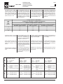
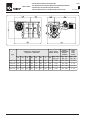
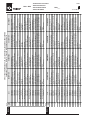
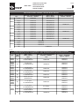
1
All rights reserved © WAMGROUP
RVS/RVC
•
BLOW-THROUGH ROTARY VALVES
•
DURCHBLASSCHLEUSEN
•
VANNES ALVEOLAIRES A
PASSAGE TANGENTIEL
•
ROTOVALVOLE A FLUSSO ATTRAVERSATO
CATALOGUE No.
TO.310
CREATION DATE
ISSUE
CIRCULATION
DATE OF LATEST UPDATE
A5
100
12.05
05.01
12.05
INDEX
RVS • RVC
INHALTSVERZEICHNIS
INDEX
INDICE
1 TECHNICAL CATALOGUE
TO.310 INDEX
INTRODUCTION.........................................................................................................................
GENERAL DIAGRAM..................................................................................................................
TECHNICAL DATA.......................................................................................................................
FINISHING....................................................................................................................................
COLOURS.....................................................................................................................................
ORDER CODES...........................................................................................................................
TOP AND BOTTOM FLANGE....................................................................................................
PIPE CONNECTION....................................................................................................................
SIMPLE STEM VALVES................................................................................................................
VALVES WITH GEAR MOTOR....................................................................................................
VALVES WITH VARIABLE SPEED MOTOR..............................................................................
DIMENSIONS...............................................................................................................................
AIR OUTLET..................................................................................................................................
DRIVE UNIT DATA.......................................................................................................................
TECHNISCHER KATALOG
EINFÜHRUNG...................................................................................................................T. .4
GERÄTEAUFBAU...................................................................................................................5
TECHNISCHE DATEN......................................................................................................... .6 →. 8
FINISH...............................................................................................................................9
FARBTÖNE............................................................................................................................ .10
BESTELLCODES..............................................................................................................11
OBERER UND UNTERER FLANSCH...........................................................................12
ROHRLEITUNGSVERBINDUNG....................................................................................13
ZELLENDRADSCHLEUSEN MIT FREIEM WELLENZAPFEN.....................................14
ZELLENDRADSCHLEUSEN MIT ANTRIEB..................................................................15
ZELLENDRADSCHLEUSEN MIT MECHANISCHEM REGELANTRIEB................... .16
PLATZBEDARF.................................................................................................................17
LUFTAUSLASS.................................................................................................................18
ANTRIEBSDATEN............................................................................................................19
CATALOGUE TECNIQUE
INTRODUCTION.........................................................................................................................
SCHEMA GENERAL....................................................................................................................
DONNEES TECHNIQUES..........................................................................................................
FINITION.......................................................................................................................................
TONALITES...................................................................................................................................
CODES DE SELECTION.............................................................................................................
BRIDE SUPERIEURE ET INFERIEURE..................................................................................
RACCORDEMENT TUBE..........................................................................................................
VANNES A ARBRE NU................................................................................................................
VANNES MOTORISÉES..............................................................................................................
VANNES AVEC MOTOVARIATEUR MECANIQUE..................................................................
ENCOMBREMENTS...................................................................................................................
SORTIE D’AIR..............................................................................................................................
CARACTÉRISTIQUES MOTORISATION.................................................................................
CATALOGO TECNICO
INTRODUZIONE................................................................................................................T. .4
SCHEMA GENERALE.......................................................................................................... .5
DATI TECNICI........................................................................................................................ .6 →. 8
FINITURA............................................................................................................................... .9
TONALITÁ............................................................................................................................... .10
CODICI DI SCELTA................................................................................................................ .11
FLANGIATURE SUPERIORE E INFERIORE..................................................................... .12
IMBOCCHI.............................................................................................................................. .13
VALVOLE AD ALBERO NUDO................................................................................................14
VALVOLE MOTORIZZATE..................................................................................................... .15
VALVOLE MOTORIZZATE CON MOTOVARIATORE DI GIRI............................................16
INGOMBRI.............................................................................................................................. .17
SCARICHI D’ARIA................................................................................................................. .18
DATI MOTORIZZAZIONE.......................................................................................................19
2 MAINTENANCE CATALOGUE
OPERATION AND MAINTENANCE..........................................................................................
PACKAGING..................................................................................................................................
STORAGE.....................................................................................................................................
TRANSPORT WEIGHTS LIFTING.............................................................................................
OPERATION AND MAINTENANCE..........................................................................................
PNEUMATIC CONNECTIONS...................................................................................................
ELECTRICAL CONNECTIONS..................................................................................................
GENERAL PRECAUTIONS........................................................................................................
COMMISSIONING PROCEDURE.............................................................................................
OPERATION..................................................................................................................................
DISMANTLING..............................................................................................................................
WEIGHTS......................................................................................................................................
INSTALLATION..............................................................................................................................
EXAMPLES OF APPLICATIONS.................................................................................................
COMPRESSED AIR REQUISITES............................................................................................
ELECTRICAL CONNECTIONS.................................................................................................
START UP - SHUT DOWN PROCEDURE...............................................................................
MAINTENANCE...........................................................................................................................
REPLACEMENT OF SEALS.......................................................................................................
ADJUSTMENT OF THE ROTOR..............................................................................................
REPLACEMENT OF RVS and RVC TIPS.................................................................................
MAINTENANCE...........................................................................................................................
CLEANING.....................................................................................................................................
NOISE- DEMOLITION MACHINE..............................................................................................
FAULT FINDING...........................................................................................................................
CHECK LIST IN CASE OF ROTARY VALVE TROUBLE..........................................................
PROBLEMS RVS..........................................................................................................................
WARTUNGSKATALOG
BETRIEBS- UND WARTUNGSANLEITUNG............................................................M .22→. 23
VERPAKUNG.....................................................................................................................24→. 25
LAGERHALTUNG............................................................................................................ .26
TRANSPORT GEWICHTE HEBEN............................................................................... .27
BETRIEBS- UND WARTUNGSANLEITUNG................................................................ .28→. 30
LUFTANSCHLUSS PNEUMATISCHE............................................................................31
ELEKTRISCHE ANSCHLÜSSE..................................................................................... .32
ALLGEMEINE VORSICHTS-MASSNAHME................................................................. .33
INBETRIEBNAHME........................................................................................................ .34
UNKTIONSWEISE............................................................................................................35
DEMONTAGE...................................................................................................................36
GEWICHTE..................................................................................................................... .37
EINBAU..............................................................................................................................38
ANWENDUNGSBEISPIELE........................................................................................... .39
ANFORDERUNGEN AN DIE DRUCKLUFT..................................................................40
ELEKTRISCHE ANSCHLÜSSE..................................................................................... .41
EINSCH - AUSSCHALTVERFAHREN.......................................................................... .42
WARTUNGSANLEITUNG.............................................................................................. .43
AUSTAUSCH DER WELLENABDICHTUNGEN............................................................44→. 45
ZELLENRADEINSTELLUNG.......................................................................................... .46
AUSTAUSCH DER SCHLEISSLEISTEN...................................................................... .47
WARTUNGSANLEITUNG.............................................................................................. .48→. 51
REINIGUNG......................................................................................................................52
BETRIEBSGERÄUSCHE - VERSCHROTTUNG...........................................................53
BETRIEBSSTÖRUNGEN UND ABHILFE......................................................................54
CHECKLISTE BEI BETRIEBSSTÖRUNGEN AN ZELLENRADSCHLEUSEN............55 →. 56
PROBLEME RVS..............................................................................................................57 →. 58
CATALOGUE D’ENTRETIEN
UTILISATION ET ENTRETIEN...................................................................................................
EMBALLAGE.................................................................................................................................
EMMAGASINAGE........................................................................................................................
TRANSPORT POIDS LEVAGE...................................................................................................
UTILISATION ET ENTRETIEN...................................................................................................
RACCORDEMENTS PNEUMATIQUE......................................................................................
BRANCHEMENTS ELECTRIQUES..........................................................................................
PRECAUTIONS
GENERALES...........................................................................................
DEMARRAGE...............................................................................................................................
FONCTIONNEMENT..................................................................................................................
DEMONTAGE...............................................................................................................................
POIDS............................................................................................................................................
INSTALLATION..............................................................................................................................
EXEMPLES D’APPLICATION.....................................................................................................
CONDITIONS REQUISES POUR L’AIR COMPRIMÉ............................................................
BRANCHEMENTS ELECTRIQUES..........................................................................................
PROCÉDURE DE MISE EN MARCE - D’ARRET...................................................................
ENTRETIEN..................................................................................................................................
SUBSTITUTION DES ÉTANCHÉITÉS......................................................................................
RÉGLAGE DU ROTOR...............................................................................................................
REMPLACEMENT DES BAVETTES.........................................................................................
ENTRETIEN..................................................................................................................................
NETTOYAGE................................................................................................................................
BRUIT - DEMOLITION A FIN DE VIE DE LA MACHINE........................................................
INCONVENIENTS POSSIBLES..................................................................................................
CHECK LIST EN CAS DE VIS EN PANNE................................................................................
PROBLÉMES RVS.......................................................................................................................
CATALOGO DI MANUTENZIONE
USO E MANUTENZIONE.............................................................................................
M .22→. 23
IMBALLO......................................................................................................................... .24→. 25
IMMAGAZZINAGGIO......................................................................................................26
TRASPORTO PESI SOLLEVAMENTO...........................................................................27
USO E MANUTENZIONE............................................................................................. .28→. 30
COLLEGAMENTI PNEUMATICI................................................................................... .31
COLLEGAMENTI ELETTRICI....................................................................................... .32
PRECAUZIONI GENERALI........................................................................................... .33
AVVIAMENTO..................................................................................................................34
FUNZIONAMENTO....................................................................................................... .35
SMONTAGGIO.................................................................................................................36
PESI..................................................................................................................................37
INSTALLAZIONE..............................................................................................................38
ESEMPI DI APPLICAZIONE.......................................................................................... .39
REQUISITI ARIA COMPRESSA................................................................................... .40
COLLEGAMENTI ELETTRICI....................................................................................... .41
PROCEDURA DI AVVIAMENTO- SPEGNIMENTO.................................................... .42
MANUTENZIONE.......................................................................................................... .43
SOSTITUZIONE TENUTE..............................................................................................44→. 45
REGOLAZIONE ROTORE............................................................................................ .46
SOSTITUZIONE BAVETTE ............................................................................................47
MANUTENZIONE.......................................................................................................... .48→. 51
PULIZIA........................................................................................................................... .52
RUMORE- ROTTAMAZIONE MACCHINA...................................................................53
POSSIBILI INCONVENIENTI........................................................................................ .54
CHECK LIST IN CASO DI GUASTO..............................................................................55 →. 56
PROBLEMI RVS............................................................................................................. .57 →. 58
3 SPARE PARTS CATALOGUE
SPARE PARTS .............................................................................................................................
ERSATZTEILKATALOG
ERSATZTEIL...............................................................................................................R .60→. 74
CATALOGUE PIECES DE RECHANGE
PIECES DE RECHANGE.....................................................................................................
CATALOGO RICAMBI
RICAMBI............................................................................................................................ R .60→. 74
RVS/RVC
•
BLOW-THROUGH ROTARY VALVES
TECHNICAL CATALOGUE
•
DURCHBLASSCHLEUSEN
TECHNISCHER KATALOGUE
•
VANNES ALVEOLAIRES A PASSAGE TANGENTIEL
CATALOGUE TECHNIQUE
•
All rights reserved © WAMGROUP
TECHNICAL CATALOGUE
1
ROTOVALVOLE A FLUSSO ATTRAVERSATO
CATALOGO TECNICO
CATALOGUE No.
TO.310.T
CREATION DATE
ISSUE
CIRCULATION
DATE OF LATEST UPDATE
A5
100
12.05
05.01
12.05
- INTRODUCTION
RVS • RVC
- EINFÜHRUNG
1
- INTRODUCTION
TO.310.T. 4
- INTRODUZIONE
TYPE
RVS - RVC
MASCHINENTYP
RVS - RVC
TYPE
RVS - RVC
TIPO
RVS - RVC
DESCRIPTION
Blow-through rotary valves
BESCHREIBUNG
Durchblasschleusen
DÉSIGNATION
Vannes alveolaires a passage
tangentiel
DESCRIZIONE
Rotovalvola a flusso attraversato
USE
RVS - RVC series of rotary valves
are conceived and designed for
use in pneumatic conveyor systems, in accordance with the quality standards required by the market.
VERWENDUNGSZWECK
Die Durchblasschleusen der
Baureihe RVS-RVC wurden für
den Einsatz in pneumatischen
Förderanlagen entwickelt und
entsprechen in vollem Umfang
dem marktüblichen Qualitätsstandard.
EMPLOI PRÉCONISÉ
Les vannes rotatives modèle RVS
- RVC sont indiquées pour être
utilisées dans les installations à
transport pneumatique, dans le
respect des standards de qualité exigés par le marché.
FUNZIONE D’USO
Le rotovalvole modello RVS - RVC
sono indicate per alimentazione
e scarico controllato di prodotti in
polvere o granulari da elementi di
immagazzinamento.
IMPROPER USE
RVS - RVC rotary valves are NOT
designed to work in dangerous
conditions or with dangerous materials. If the equipment has to operate in these conditions, the
Manufacturer must be informed.
KONTRAINDIKATIONEN
Die Durchblasschleusen der
Modellreihe RVS-RVC sind weder für gefährliche Anwendungen noch zum Handling von gefährlichen Medien geeignet. Sollte der Betreiber eine RVS-RVCSchleuse für gefährliche Medien bzw. Anwendungen einsetzen wollen, so muß er zuvor
den Hersteller um Erlaubnis fragen.
CONTRE-INDICATIONS
Les vannes rotatives standards de
la classe RVS - RVC N’ONT PAS
été projetées pour travailler dans
des conditions ou avec des produits dangereux; par conséquent
si la machine doitrat répondre à
ces exigences le constructeur doit
obligatoirement en être informé.
CONTROINDICAZIONI
Le rotovalvole modello RVS - RVC
sono concepite e progettate per
l’impiego in impianti a trasporto
pneumatico, nel rispetto degli
standard qualitativi richiesti dal
mercato.
Dangerous materials:
• explosives
• toxic
• flammable
• harmful and similar
Als gefährliche Medien gelten:
• explosive,
• giftige,
• feuergefährliche
• in irgendeiner Weise schädliche
Les produits suivants sont considérés dangereux:
• explosifs,
• toxiques,
• inflammables,
• nocifs et/ou similiares.
Si ritengono materiali pericolosi:
• esplosivi,
• tossici,
• infiammabili,
• nocivi e/o simili.
Dangerous applications:
• extracting the materials listed
above from silos or storage containers.
Als gefährliche Anwendungen gelten:
• der Austrag von den oben genannten Medien aus Silos oder
anderen Behältern.
Les applications suivantes sont
considérées dangereuses:
• extraction des silos ou cellules
contenant les produits indiqués
ci-dessus
Si ritengono applicazioni pericolose:
• estrazioni da silo o celle contenenti i suddetti materiali
TEMPERATURE
- 20°C + 60°C standard execution
- 20°C +150°C special execution
BETRIEBSTEMPERATUR
- 20°C + 60°C Standardausführung
- 20°C +150°C Spezialausführung
TEMPERATURE D’UTILISATION
- 20°C + 60°C Version standard
- 20°C +150°C Version spéciale
TEMPERATURE
- 20°C + 60°C
Esecuzione standard
- 20°C +150°C
Esecuzione speciale
12.05
- GENERAL DIAGRAM
RVS • RVC
- GERÄTEAUFBAU
- SCHEMA GENERALE
Item
Pos.
1
- SCHEMA GENERAL
Description - Bezeichnung
Désignation - Descrizione
TO.310.T. 5
Quantity - Menge
Quantitè - Quantità
1
Casing - Gehäuse
Corps - Corpo
1
2
Rotor - Zellenrad
Rotor - Rotore
1
3
Drive plate - Antriebslagerschild
Couvercle motorsation - Coperchio porta motorizzazione
1
4
Motor driven or bare shaft - Antriebswellenzapfen
Arbre type motorisé ou type nu - Albero tipo motorizzato o tipo nudo
1
5
Cover plate opposite drive end - Abtriebsseitiger Lagerschild
Couvercle opposé motorisation - Coperchio lato folle
1
6
Scraper set - Abstrieferset
Groupe racleure - Gruppo raschiatore
1
7
Conveying pipe connection - Förderleitungsanschluß
Connexion tube de transport - Imbocco tubo di trasporto
2
12.05
- TECHNICAL DATA
RVS • RVC
- TECHNISCHE DATEN
1
- DONNEES TECHNIQUES
TO.310.T. 6
- DATI TECNICI
- Dimensions, footprint and rating
are detailed in the next pages.
- Noise level: <85 dB(A).
- Einbaumaße und Leistungsdaten sind auf den folgenden Seiten angegeben.
- Geräuschpegel < 85 dB(A).
- Les dimensions, encombrements et puissances sont indiqués dans les fiches ci-dessous.
- Le niveau sonore est inférieur à
85 dB(A).
- Dimensioni, ingombri e potenze applicate sono indicati nelle
schede seguenti.
- Livello di rumorosità inferiore a
85 dB(A).
- Performance graph:
- Leistungsdiagramm:
- Diagramme des performances:
- Diagramma prestazioni:
r.p.m. - min-1
tpm - giri/min
10
Type
20
Throughput - Durchsatz
Débit - Portata
Max. pressure differential
Max. Druckdifferenz
Diff. maxi de pression
Diff. max. di pressione
Operating temperature
Betriebstemperatur
Température d'emploi
Temperature d'utilizzo
bar
°C
30
litres per rev.
Liter pro Umdrehung
litres par tour
litri al giro
Throughput - Durchsatz
Débit - Portata
m3/h
RVS/C 10
5.4
10.8
16.2
9
0.7
-20 ÷ +60
RVS/C 15
8.4
16.8
25.2
14
0.7
-20 ÷ +60
RVS/C 20
12
24
36
20
0.7
-20 ÷ +60
RVS/C 35
22.8
45.6
68.4
38
0.7
-20 ÷ +60
Loading
Füllgrad
Coefficient de remplissage
Coefficiente di riempimento
1
THROUGHPUT - DURCHSATZLEISTUNG - DEBIT - PORTATA
80
70
60
RVS/C 10
RVS/C 15
RVS/C 20
RVS/C 35
m3/h
50
40
30
20
10
0
0
5
10
15
min -1
20
25
30
12.05
- TECHNICAL DATA
RVS • RVC
- TECHNISCHE DATEN
1
- DONNEES TECHNIQUES
TO.310.T. 7
- DATI TECNICI
LOSS OF AIR - LUFTVERLUST - PERTES D’AIR - PERDITE D’ARIA
Losses due to pressure differential during operation - Verluste infolge Druckdifferenzen während des Betriebs
Pertes dûes au différentiel de pression durant l'exercice - Perdite dovute al differenziale di pressione in esercizio
120
100
Nm3/h
80
RVS 10
RVS 15
60
RVS 20
RVS 35
40
20
0
0,2
1
0,4
2
0,6
3
0,8
4
bar
VOLUMETRIC CAPACITY - FASSUNGSVERMÖGEN - CAPACITE VOLUMETRIQUE - VOLUME GENERATO DALLA VALVOLA
80
70
60
RVS 10
Nm3 / h
50
RVS 15
40
RVS 20
30
RVS 35
20
10
0
10
1
20
2
rpm
30
3
12.05
- TECHNICAL DATA
RVS • RVC
- TECHNISCHE DATEN
1
- DONNEES TECHNIQUES
TO.310.T. 8
- DATI TECNICI
- The loading ratio in case of
powders or similar materials
varies accordino to the flowability of the material and rotor
rotation speed. Powder loading coefficient (at optimum
speed of 20 rpm) = 0.8.
r.p.m.
min -1
tpm
giri/min
- Der Füllkoeffizient ändert sich
bei staubförmigen oder ähnlichen Gütern mit der Rieselfähigkeit des Materials und der
Rotationsgeschwindigkeit des
Rotors. Bei staubförmigem
Schüttgut und der optimalen
Drehzahl von 20 min-1 beträgt
der Füllgrad 80%.
- Dans le cas des poudres ou des
matières similaires le coefficient
de remplissage varie en fonction de la fluidité du produit et
de la vitesse de rotation du rotor. Coefficient de remplissage
pour les poudres (à vitesse optimale 20 TR/MIN) = 0.8.
- Il coefficiente di riempimento nel
caso di polveri o materiali simili
varia in funzione della scorrevolezza del prodotto e della velocità di rotazione del rotore. Coefficiente di riempimento per
polveri (a velocità ottimale 20
RPM): 0.8.
Loading coefficient - Füllkoeffizient
Coefficient de remplissage - Coefficiente di riempimento
Material - Schüttgut - Matériau - Materiale
very free flowing - gut rieselfähig
très fluide - molto scorrevole
free flowing - rieselfähig
fluide - scorrevole
poorly flowing - schwach rieselfähig
peu fluide - poco scorrevole
< 10
0.9
0.85
0.8
10 ÷ 20
0.8
0.75
0.7
> 20
0.7
0.65
0.6
- Available speeds 10/20/30
RPM; speed variator 4-22 RPM.
- Standard-Drehzahl für Antriebe
mit konstanter Drehzahl = 10/
20/30 min-1; Standard-Regelbereich für mechanische Regelantriebe = 4 bis 22 min-1.
- Vitesses de base disponibles
10/20/30 TR/MIN; variateur avec
plage de 4-22 TR/MIN.
- Velocità di base disponibili 10/
20/30 RPM; variatore con campo 4-22 RPM.
- Wear is reduced at lower operating speeds. It is best to use
large cubic capacity at slow
speeds.
- Je niedriger die Drehzahl, desto
geringer ist der Verschleiß. Besonders bei abrasiven Medien
sollten daher großvolumige und
langsam drehende Schleusen
verwendet werden.
- Limitation de l’usure aux vitesses les plus basses: l’utilisation
de grandes cylindrées à basse
vitesse est recommandée.
- Limitazione dell’usura alle velocità più basse: è consigliabile
impiegare grandi cilindrate a
basse velocità.
- Different fabrication materials for
various products and applications.
- Die Wahl des Werkstoffes ist
vom Produkt abhängig (siehe
nachfolgende allgemeine Richtlinien zur Wahl des geeigneten
Werkstoffes).
- Matériaux de construction en
fonction des caractéristiques
des produits.
- Materiali costruttivi in funzione
delle caratteristiche dei prodotti.
A
Material for use with noncontaminating products:
Medien ohne besondere
Eigenschaften:
Application diverses de matières
Applicazioni varie di materiali
ne pouvant pas être contaminées: non contaminabili:
Body:
Cover:
Rotor:
Gehäuse: Grauguß
Endschilde: Grauguß
Zellenrad: Stahl
Corps:
Fonte grise
Couvercles: Fonte grise
Rotor:
Acier
Corpo:
Ghisa grigia
Coperchi: Ghisa grigia
Rotore:
Acciaio
Abrasive Medien:
Produits abrasifs:
Prodotti abrasivi:
grey cast iron
cast iron
steel
Abrasive products:
Gehäuse:
chromium or nickel plated
cast iron
Endschilde:
Covers: chromium or nickel plated
cast iron
Rotor: steel with Vulkolan scrapers Zellenrad:
Body:
B
C
verchromter oder
Corps:
vernickelter Grauguß
verchromter oder
Couvercles:
vernickelter Grauguß
Rotor:
Stahl mit Schleißleisten aus Vulkolan
Fonte grise chromée ou Corpo:
nickelée
Fonte grise chromée ou Coperchi:
nickelée
Acier avec bavettes en Rotore:
Vulkolan
Corrosive products:
Korrosive Medien:
Produits corrosifs:
Body:
nickel plated cast iron
Covers: nickel plated cast iron
Rotor: nickel plated cast iron
Gehäuse: vernickelter Grauguß Corps:
Fonte grise nickelée
Endschilde: vernickelter Grauguß Couvercles: Fonte grise nickelée
Fonte grise nickelée
Zellenrad: vernickelter Grauguß Rotor:
Ghisa grigia cromata o
nichelata
Ghisa grigia cromata o
nichelata
Acciaio con bavette in
Vulkolan
Prodotti corrosivi:
Corpo:
Ghisa grigia nichelata
Coperchi: Ghisa grigia nichelata
Rotore: Ghisa grigia nichelata
12.05
- FINISHING
- FINISH
RVS • RVC
1
- FINITION
TO.310.T. 9
- FINITURA
*
3
3
Finishing
Finish
Finissage
Finitura
Paint
Anstrich
Peinture
Verniciatura
0
**
0
3
0
INTERNAL - INNEN - INTERIEUR - INTERNO
0
0
Paint
Anstrich
Peinture
Verniciatura
none
keiner
aucune
nessuna
Paint colour
Farbton Anstrich
Tonalité
Tonalità
none
keiner
aucune
nessuna
EXTERNAL - AUßEN - EXTERIEUR - ESTERNO
3
1)
2)
O
A
B
C
D
E
F
G
H
I
L
M
N
P
X
Y
Z
RAL 1013
RAL 1015
RAL 5010
RAL 5015
RAL 6011
RAL 7035
RAL 7032
RAL 7001
RAL 9001
RAL 9002
RAL 9010
Paint
Anstrich
Peinture
Verniciatura
1 primer+
1 paint coat
1x Grund+
1x Deck
1 antirouille+
1 peinture
1 mano
+ 1 mano
Paint colour
Farbton Anstrich
Tonalité
Tonalità
none
yellow Caterpillar*
pearl white
light ivory
gentian blue*
sky blue
reseda green
light grey*
pebble grey
silver grey
cream white
grey white
pure white
alluminium
ecological colour
non ecological colour
to be specified
Keiner
Caterpillar gelb*
Perlweiss
Hellelfenbein
Enzianblau*
Himmelblau
Resedagrün
Lichtgrau*
Kieselgrau
Silbergrau
Cremeweiß
Grauweiß
Reinweiß
Aluminium
Ökofarben
Nicht-Ökofarben
Zu spezifizieren
aucune
jaune Caterpillar*
blanc perle
ivoire clair
bleu gentiane*
bleu ciel
vert réséda
gris lumière*
gris gravier
gris argent
blanc crème
blanc gris
blanc pur
Aluminium
Tonalité écologiques
Tonalités non écologiques
à préciser
nessuna
giallo Caterpillar*
bianco perla
avorio chiaro
blu genziana*
blu cielo
verde reseda
grigio luce*
grigio ghiaia
grigio argento
bianco crema
bianco grigio
bianco puro
Alluminio
Tonalità ecologiche
Tonalità non ecologiche
su specifica
* Recommended colours
* Empfohlene Farben
* Tonalités conseillées
* Tonalità consigliate
1) See Table X page T.10
2) See Table Y page T.10
Specify colours in tables X and Y
in the order.
1) Siehe Tabelle X, Seite T.10
2) Siehe Tabelle Y, Seite T.10
Farbtöne für Tabellen X und Y in
der Bestelung angeben.
1) Voir tab. X, page T.10
2) Voir tab. Y, page T.10
Spécifier Tonalités pour tab.
X et Y dans la commande.
1) Vedi Tab. X pag. T.10
2) Vedi Tab. Y pag. T.10
Le tonalità delle tabelle X e Y devono essere specificate nell’ordine.
The antirust is a red-brown colour.
Farbton Grundanstrich = rotbraun.
Tonalité antirouille = rouge-marron.
Tonalità antiruggine = rosso-marrone.
RVS • RVC
- COLOURS
12.05
- FARBTÖNE
1
- TONALITES
TO.310.T. 10
- TONALITÀ
X
- “ECOLOGICAL” RAL COLOURS THAT DO NOT CONTAIN LEAD OR CHROME
- “ÖKOLOGISCHE” RAL-TÖNE OHNE BLEI- UND CHROMANTEILE
- TONALITES RAL “ECOLOGIQUES” SANS CHROME ET PLOMB
- TONALITÀ RAL “ECOLOGICHE” SENZA CROMO E PIOMBO
1000
1001
1002
1011
1014
1019
3005
3007
3009
3027
4001
4004
4005
4006
4007
4008
5000
5001
6000
6003
5002
5003
5004
5005
5507
5008
5009
5011
5012
5013
5014
5017
6004
6006
6012
6013
6015
6016
6019
6020
6021
6022
6025
6026
6027
6028
6033
6034
7000
7024
7002
7003
7004
7005
7006
7007
7008
7009
7010
7011
7012
7013
7015
7016
7021
7022
7023
7025
7026
7030
7031
7033
7034
7036
7037
7038
7039
7040
7042
7043
7044
8000
8001
8002
8004
8011
8015
8016
8017
8019
8022
8024
8025
8028
9003
9004
9005
9011
9016
9017
9018
Y
- “NON ECOLOGICAL” RAL COLOURS CONTAINING LEAD OR CHROME
- NICHT “ÖKOLOGISCHE” RAL-TÖNE MIT BLEI- UND CHROMANTEILEN
- TONALITES RAL “NON ECOLOGIQUES” AVEC CHROME ET PLOMB
- TONALITÀ RAL “NON ECOLOGICHE” CONTENENTI CROMO - PIOMBO
RAL 1006
Maize yellow
Maisgelb
Jaune mais
Giallo mais
RAL 1007
Chrome yellow
Chromgelb
Jaune chrome
Giallo cromo
RAL 1018
Zinc yellow
Zinkgelb
Jaune zinc
Giallo zinco
RAL 2008
Light red orange
Hellrotorange
Rouge orange clair
Arancio rosso chiaro
RAL 6017
May green
Maigrün
Vert mai
Verde maggio
RAL 6018
Yellow green
Gelbgrün
Vert jaune
Verde giallo
12.05
- ORDER CODES
RVS • RVC
- BESTELLCODES
1
- CODES DE SELECTION
TO.310.T. 11
- CODICI DI SCELTA
RVS
10
20
1
A
A
0
A
ROTOR
ZELLENRAD
ROTOR
ROTORE
C
H
BODY TREATMENT
BEHANDLUNG GEHÄUSE
TRAITEMENT CORPS
TRATTAMENTO CORPO
Teflon coated
Teflon-beschichtet
Téflonné
Teflonato
Stainless Steel 304
Edelstahl 1.4301
Inox 304
AISI 304
B
Chromé
Cromato
Nickel coated
Vernickelt
0
C Nickelé
Nichelato
SEALS
WELLENABDICHTUNGEN
JOINTS
TENUTE
TIP SCRAPERS
SCHLEISSLEISTEN
BAVETTES
BAVETTE
A
Cast iron
Bare shaft
Viton ®
®
Viton
®
Viton
Viton ®
giri al minuto
Vulkolan e Raschiatore
Scraper
316 Stainless Steel (only for size 10 and 20)
Edelstahl 1.4401 (nur für Größe 10 und 20)
Inox AISI 316 (seulement pour taille 10 et 20)
Inox AISI 316 (solo per grandezze 10 e 20)
RPM
48
giri al minuto
giri al minuto
Without motor with gear reducer 10 RPM
SP Ohne Motor mit Getriebe 10 RPM
Sans moteur avec réducteur 10 RPM
Senza motore con riduttore 10 RPM
SM
Without tip scrapers
Ohne Schleißleisten
Sans bavettes
Senza bavette
Speed variator without motor
Regelantrieb ohne Motor
Variateur sans moteur
Variatore meccanico senza motore
VS
-1
0
Raschiatore
5
30 min
TR/MIN
Motor 4/8 poles
Motor 4/8 polig
Moteur 4/8 polês
Motore 4/8 poli
without motor
ohne E-Motor
sans moteur
senza motore
Chain transmission 10 RPM
NEMA standards gear red.
Teflon et Racleur
Teflon e Raschiatore
304 Stainless Steel (only for size 10 and 20)
Edelstahl 1.4301 (nur für Größe 10 und 20)
Inox AISI 304 (seulement pour taille 10 et 20)
Inox AISI 304 (solo per grandezze 10 e 20)
RPM
-1
Standard
Standard
Standard
Standard
5 Teflon und Abstreifer
Vulkolan and Scraper
Variateur
Variatore meccanico
20 min
TR/MIN
0
Teflon and Scraper
Teflon
Teflon
Teflon
Teflon
Speed variator
Arbre nu
Albero nudo
-1
D
Purged seals
Sperrspülungen
Etanchéités fluxées
Tenute flussate
und Abstreifer
3 Vulkolan
1 Abstreifer
Vulkolan et Racleur
Racleur
AN Freie Welle ohne Antrieb V M Regelantrieb
RPM
B
2
1 Grauguß
10 min
TR/MIN
Standard
Standard
Standard
Standard
High temperature resistant purged seals
Sperrspülungen für hohe Temperatur
Etanchéités fluxées Haute température
Tenute flussate Alta temperatura
B
Standard
Standard
Standard
Standard
AISI 316
C
Fonte
Ghisa
DRIVE UNIT
ANTRIEB
MOTORISATION
MOTORIZZAZIONE
Stainless Steel 316
High temperature
Hohe Temperatur
Haute température
Alta temperatura
Vulkolan
Vulkolan
Vulkolan
Vulkolan
0
1.4401
M Edelstahl
Inox 316
A
Viton® and Scraper
Viton® und Abstreifer
4 Viton® et Racleur
Viton® e Raschiatore
MATERIAL BODY
GEHÄUSE STOFFE
MATERIAUX CORPS
MATERIALE CORPO
Nickel plated
Vernickelt
Nickelé
Nichelato
Teflon coated
Teflon-beschichtet
Teflonné
Teflonato
Chromium plated
A Verchromt
D
without gear red.
SR ohne Getriebe
sans réducteur
senza riduttore
Chain transmission 20 RPM
20RPM
10RPM
2C Kettentrieb
1C Kettentrieb
Entraînement par chaîne 20 RPM
Entraînement par chaîne 10 RPM
NC NEMA-Norm-Getriebe
réducteur NEMA
Trasmissione a catena 10RPM
riduttore norme NEMA
Trasmissione a catena 20RPM
Chain transmission without gear reducer
Chain transmission 30 RPM
30RPM
TS Kettentrieb ohne Getriebemotor
2C Kettentrieb
Transmission à chaîne sans motoréducteur
Entraînement par chaîne 30 RPM
Trasmissione a catena 30RPM
SIZE
GRÖßE
TAILLE
GRANDEZZA
RVS - RVC
10
15
20
35
Trasmissione a catena senza motoriduttore
10 Litres for revolution - Liter pro Umdrehung - litres pour tour - litri per giro
15 Litres for revolution - Liter pro Umdrehung - litres pour tour - litri per giro
20 Litres for revolution - Liter pro Umdrehung - litres pour tour - litri per giro
35 Litres for revolution - Liter pro Umdrehung - litres pour tour - litri per giro
RVS Blow-through rotary valve
RVS Durchblasschleuse
RVS Vanne alvéolaire à passage tangentiel
RVS Rotovalvola a flusso attraversato
RVC Fall-through rotary valve
RVC Freifallschleuse
RVC Vanne alvéolaire à chute
RVC Rotovalvola a caduta
12.05
- TOP AND BOTTOM FLANGE
RVS • RVC
- OBERER UND UNTERER FLANSCH
1
- BRIDE SUPERIEURE ET INFERIEURE
TO.310.T. 12
- FLANGIATURE SUPERIORE E INFERIORE
B1
B2
C1
E2
E3
E3
n°
220 585 332 300 540
180
Type
A1
A2
C2
D1
RVS/C 35
470
240 585 352 480
RVS/C 20
337
196 428
RVS/C 15
276
148 342 222 276
158 342 222
RVS/C 10
238
135 298 200 235
135 298 200
278 337 200 428
D2
F2
F3
F3
N°
G1
G1
N°
G2
N°
3
300 540
180
3
M 12
8
14
8
195
2
250 390
195
2
M 12
6
13
6
194 310
155
2
194 310
155
2
M 10
6
12
6
172 270
135
2
172 270
135
2
M8
6
10
6
E1
278 250 390
F1
12.05
- PIPE CONNECTION
RVS • RVC
- ROHRLEITUNGSVERBINDUNG
1
- RACCORDEMENT TUBE
TO.310.T. 13
- IMBOCCHI
RVS 35
RVS 15
2 x Ø14
2 x Ø10
10
24
30
Ø140.5
16
Ø118
15
Ø127
30
185
Ø74
10
Ø81
20
116
220
136
RVS 20
RVS 10
2 x Ø13
2 x Ø9
9
28
20
Ø115
15
Ø96
14
Ø103
30
145
173
Ø64
9
Ø71
18
90
108
Only for RVS - Nur für RVS - Seulement pour RVS - Solo per RVS
12.05
- SIMPLE STEM VALVES
RVS • RVC
- ZELLENDRADSCHLEUSEN MIT FREIEM WELLENZAPFEN
1
- VANNES A ARBRE NU
TO.310.T. 14
- VALVOLE AD ALBERO NUDO
Type
A1
A2
B1
B2
C1
C2
D1
D2
E1
E2
E3
F1
F2
RVS 35
470
240
585
352
480
220
585
332
300
540
180
300
540
RVS 20
337
196
428
278
337
200
428
278
250
390
195
250
390
RVS 15
276
148
342
222
276
158
342
222
194
310
155
194
310
RVS 10
238
135
298
200
235
135
298
200
172
270
135
172
270
Type
F3
G1
G1
N°
G2
G2
N°
H
I
J
K
L
M
N
P
RVS 35
180
M 12
8
14
8
530
118
105
185
430
732
72
40
RVS 20
195
M 12
6
13
6
447
96
88
160
362
592
70
32
RVS 15
155
M 10
6
12
6
399
74
69
153
323
504
76
32
RVS 10
135
M8
6
10
6
339
64
54
129
280
455
58
28
12.05
- VALVES WITH GEAR MOTOR
RVS • RVC
- ZELLENDRADSCHLEUSEN MIT ANTRIEB
1
- VANNES MOTORISÉES
TO.310.T. 15
- VALVOLE MOTORIZZATE
r.p.m.
min-1
tpm
giri/min
30
20
Type
Q1
Q2
Q3
R1
R2
R3
H
kW
Giri
RVS/C 35
890
558
332
740
217
523
530
2.2
1400
RVS/C 20
705
444
261
608
181
426
447
1.5
1400
RVS/C 15
605
390
215
588
162
426
399
1.1
1400
RVS/C 10
572
372
200
560
140
420
339
0.75
1400
RVS/C 35
890
558
332
740
217
523
530
1.5
900
RVS/C 20
705
444
261
608
181
426
447
1.1
900
RVS/C 15
605
390
215
588
162
426
399
0.75
900
RVS/C 10
572
372
200
560
140
420
339
0.55
900
RVS/C 35
890
558
332
740
217
523
530
*1.1
900
RVS/C 20
658
397
261
591
181
410
447
*0.75
1400
RVS/C 15
585
370
215
572
162
410
399
0.55
1400
RVS/C 10
542
342
200
527
140
387
339
*0.37
1400
10
*
*
*
*
Motor - Motor
Moteur - Motore
Dimensions - Abmessungen - Dimensions - Dimensioni
The dimensions given refer to valves with standard drive.
Werte beziehen sich auf Standardantriebe.
Mesures se rapportant à la vanne avec motorisation standard.
Quote riferite alla valvola con motorizzazione standard.
Pretorque
Vorgelege
Précouple
Precoppia
no - nein
no - no
yes - ja
oui - si
yes - ja
oui - si
yes - ja
oui - si
12.05
- VALVES WITH VARIABLE SPEED MOTOR
RVS • RVC
- ZELLENDRADSCHLEUSEN MIT MECHANISCHEM REGELANTRIEB
- VALVOLE MOTORIZZATE CON MOTOVARIATORE DI GIRI
Motor - Motor
Moteur - Motore
Dimensions - Abmessungen
Dimensions - Dimensioni
Type
1
- VANNES AVEC MOTOVARIATEUR MECANIQUE
TO.310.T. 16
Variator
Regelgetriebe
Variateur
Variatore
Rotor
Rotor
Rotor
Rotore
Q1
Q2
Q3
R1
R2
R3
H
kW
rpm - min-1
tpm - giri
rpm - min-1
tpm - giri
rpm - min-1
tpm - giri
RVS/C 35
930
596
332
870
217
653
530
1.5
1400
190 - 1000
4 - 20
RVS/C 20
788
527
261
743
181
562
447
0.75
1400
190 - 1000
4 - 20
RVS/C 15
639
424
215
724
162
562
399
0.75
1400
190 - 1000
4 - 20
RVS/C 10
474
380
200
615
140
475
339
0.37
1400
190 - 1000
4 - 20
12.05
- DIMENSIONS
RVS • RVC
- PLATZBEDARF
1
- ENCOMBREMENTS
TO.310.T. 17
- INGOMBRI
RVS/C
10
15
20
35
A
B
C
D
E
Power - Leistung
Puissance - Potenza
(kW)
Torque - Drehmoment
Couple - Coppia
(Nm)
310
0.37
300
310
0.55
232
10 rpm
630
20 rpm
630
30 rpm
630
310
0.55
149
10 rpm
700
360
0.55
472
20 rpm
650
310
0.75
328
545
627
492
620
390
430
30 rpm
650
310
1.1
308
10 rpm
700
340
0.55
472
20 rpm
650
290
0.75
328
672
620
460
30 rpm
650
290
1.1
308
10 rpm
700
240
1.1
929
20 rpm
750
190
1.5
633
30 rpm
750
190
2.2
630
796
810
580
12.05
- AIR OUTLET
RVS • RVC
- LUFTAUSLASS
1
- SORTIE D’AIR
TO.310.T. 18
- SCARICHI D’ARIA
Type
A
B
C
D
RVS/C 10
145
63
213
3/4" GAS
RVS/C 15
166
72
253
3/4" GAS
RVS/C 20
181
100
279
3/4" GAS
RVS/C 35
217
160
332
3/4" GAS
12.05
- DRIVE UNIT DATA
RVS • RVC
- ANTRIEBSDATEN
1
- CARACTÉRISTIQUES MOTORISATION
TO.310.T. 19
- DATI MOTORIZZAZIONE
Locked rotor torque/
Locked rotor current/
Speed Current Voltage
Efficiency
Rated Torque
rated torque
rated courrent
Power factor
No
of
Leistung
Drehzahl Strom Spannung Wirksamkeit
Nenndrehmoment
Drehmoment blockiert Rotor/ Strom blockierter Rotor/
Leistungsfaktor
Size
Puissance poles Vitesse Courant Tension
Efficacité
Couple nominal
Nenndrehmomen
Nenndrehmomen
Facteur de
Baugröße
Potenza N.pole Velocità Corrente Voltaggio Efficienza
Coppia nominale
Couple rotor bloqué/
Courant rotor bloqué/
puissance
Taille
N.pôles
Couple nominal
Couple nominal
Fattore di
Taglia
N.poli
Coppia rotore bloccato/
Corrente a rotore bloccato/
potenza
(kW)
(tr/min)
(A)
(V)
(% )
(Nm)
coppia nominale
coppia nominale
Power
Type
RVS
10
RVS
15
RVS
20
RVS
35
10 rpm
71
0.37
4
1400
1,1
380
67.0
0.75
2.52
2.1
5,2
20 rpm
80
0.5
6
930
1,8
380
65.0
0.72
5.13
1.9
4.7
30 rpm
80
0.5
4
1410
1.6
380
71.0
0.75
3.39
2.4
5.2
VM
71
0.37
4
1400
1.1
380
67.0
0.75
2.52
1.9
5.2
TC 10 rpm
71
0.37
4
1400
1.1
380
67.0
0.75
2.52
1.9
5.2
TC 20 rpm
80
0.55
6
900
1.8
380
65.0
0.72
5.84
1.9
4.7
TC 30 rpm
80
0.55
4
1400
1.6
380
71.0
0.75
3.75
2.4
5.2
10 rpm
80
0.55
4
1400
1.6
380
71.0
0.75
3.75
2.4
5.2
20 rpm
90
0.75
6
940
2.3
380
69.0
0.72
7.62
2.0
5.5
30 rpm
90
1.1
4
1410
2.9
380
75.0
0.77
7.45
2.3
6.0
VM
80
0.75
4
1410
2.0
380
73.0
0.77
5.08
2.4
6.0
TC 10 rpm
80
0.55
4
1400
1.6
380
71.0
0.75
3.75
2.4
5.2
TC 20 rpm
90
1.1
6
900
3.2
380
72.0
0.73
11.67
2.0
5.5
TC 30 rpm
90
1.1
4
1410
2.9
380
75.0
0.77
7.45
2.3
6.0
10 rpm
80
0.75
4
1410
2.0
380
73.0
0.77
5.08
2.4
6.0
20 rpm
80
0.55
6
900
1.8
380
65.0
0.72
5.84
1.9
4.7
30 rpm
90
1.5
4
1410
3.7
380
78.0
0.79
10.16
2.3
6.0
VM
80
0.75
4
1410
2.0
380
73.0
0.77
5.08
2.4
6.0
TC 10 rpm
80
0.5
4
1410
1.6
380
71.0
0.75
3.39
2.4
5.2
TC 20 rpm
90
1.1
6
900
3.2
380
72.0
0.73
11.67
2.0
5.5
TC 30 rpm
90
1.1
4
1410
2.9
380
75.0
0.77
7.45
2.3
6.0
10 rpm
-
1.5
6
900
3.9
380
76.0
0.76
15.92
2.0
5.5
20 rpm
-
1.5
6
900
3.9
380
76.0
0.76
15.92
2.0
5.5
30 rpm
-
2.2
4
1410
5.2
380
80.0
0.81
14.90
2.3
7.0
VM
-
1.5
4
1410
3.7
380
78.0
0.79
10.16
2.3
6.0
TC 10 rpm
90
1.1
4
1410
2.9
380
75.0
0.77
7.45
2.3
6.0
TC 20 rpm
100
1.5
6
900
3.9
380
76.0
0.76
15.92
2.0
5.5
TC 30 rpm
100
2.2
4
1410
5.2
380
80.0
0.81
14.90
2.3
7.0
MAINTENANCE
2
RVS/RVC
•
BLOW-THROUGH ROTARY VALVES
INSTALLATION, OPERATION AND MAINTENANCE
•
DURCHBLASSCHLEUSEN
EINBAU, BETRIEBS- UND WARTUNGSANLEITUNG
•
VANNES ALVEOLAIRES A PASSAGE TANGENTIEL
INSTALLATION, UTILISATION ET ENTRETIEN
All rights reserved © WAMGROUP
•
ROTOVALVOLE A FLUSSO ATTRAVERSATO
INSTALLAZIONE USO E MANUTENZIONE
CATALOGUE No.
TO.310.M
CREATION DATE
ISSUE
CIRCULATION
DATE OF LATEST UPDATE
A5
100
12.05
05.01
- OPERATION AND MAINTENANCE
RVS • RVC
- BETRIEBS- UND WARTUNGSANLEITUNG
- UTILISATION ET ENTRETIEN
- USO E MANUTENZIONE
This “OPERATING AND MAINTENANCE MANUAL” is an essential and integral part of the equipment and must be readily available to operating and servicing personnel.
The owner, operator and maintenance manager must be familiar
with the contents of this Manual.
The description and illustrations
used in this Manual are not binding on the Manufacturer.
While the basic characteristics of
the equipment remain unchanged
as described, the Manufacturer
reserves the right to make any
modifications to assemblies, parts
and accessories it deems necessary for product improvement on
for fabrication or marketing needs
and this without prior notice and
without being obliged to update
this Manual at the time of modifications.
GENERAL PROHIBITIONS AND
REGULATIONS
• This equipment must not be
used even partially by unauthorised personnel.
• The shop foreman or department manager is responsible
for machine operator training
and for checking training level
achieved.
• The machine must not be used
for purposes other than those is
was designed for.
• Read carefully the warning notices attached to the machine.
• Do not remove the warning notices attached to the machine.
• When the machine is running,
do not service, repair, regulate
the machine or carry out any
other operation not strictly required by the work cycle. Before any of the above listed operations, always disconnect the
machine from all electric power supply sources.
• Do not remove the guards and
the safety devices on the machine.
• Do not start to work with protections opened or do not open
them during the work.
• Always wear safety gloves when
working on the machine.
• At the end of the work shift, disconnect the machine from the
electric and hydraulic supply.
• Any repair, service or maintenance work, whether electrical
or otherwise, must be in compliance with CEI standards 64.8
462.2 463.1 573.3.
Die “BETRIEBS- UND WARTUNGSANLEITUNG” gehört zum
Gerät und muß an einem Ort aufbewahrt werden, der dem Bedienungs- und Wartungspersonal
gut zugänglich ist.
Betreiber, Bediener und Wartungspersonal sind verpflichtet,
den Inhalt dieses Handbuchs zu
kennen.
Unter Beibehaltung der wesentlichen Merkmale der beschriebenen Geräte behält sich der Hersteller vor, jederzeit an Geräteteilen und/oder am Zubehör Änderungen im Interesse der Produktverbesserung oder aus
technisch oder kaufmännisch
notwendigen Gründen vorzunehmen.
ALLGEMEINE VORSCHRIFTEN
• Jegliche auch teilweise Bedienung des Geräts durch hierzu
nicht ausdrücklich autorisiertes
Personal ist untersagt.
• Der Betriebsleiter ist dafür verantwortlich, daß das zur Bedienung autorisierte Personal in der
Bedienung des Geräts geschult
wird.
• Das Gerät darf zu keinem anderen Zweck als zu dem in diesem Handbuch beschriebenen
verwendet werden.
• Die Gefahren- und Hinweisschilder an der Maschine müssen
beachtet werden.
• Es ist verboten, die Gefahrenund Hinweisschilder an der Maschine zu entfernen.
• Wartungs-, Reparatur-, und/
oder vom Hersteller autorisierte
Änderungsarbeiten dürfen nicht
bei laufendem Gerät durchgeführt werden. Vor der Durchführung solcher Arbeiten muß zuerst die Stromversorgung zum
Gerät unterbrochen werden.
• Es ist verboten, die an der Maschine angebrachten Schutzund Sicherheitseinrichtungen zu
entfernen.
• Schutzeinrichtungen am Gerät
dürfen bei Kontroll-, Wartungs-,
Reparatur- und/oder Änderungsarbeiten weder fehlen noch während dieser Arbeiten entfernt
werden.
• Nur mit Schutzhandschuhen am
Gerät arbeiten.
• Bei Betriebsende immer die
Stromzufuhr oder, falls vorhanden, den Hydraulikkreislauf abschalten.
• Für alle elektrischen und nicht
elektrischen Wartungsarbeiten
die Vorschriften der Normen IEC
64-8 462.2 463.1 573.3 beachten.
La présente notice “UTILISATION
ET ENTRETIEN” fait partie intégrante de la machine est elle doit
être mise à la disposition du personnel préposé à la conduite et à
la maintenance de la machine.
L’utilisateur, le conducteur et le
technicien de maintenance ont
l’obligation de connaître le contenu de cette notice d’instructions.
Les descriptions et les illustrations contenues dans la présente publication sont données sans
engagement de la part du constructeur.
Bien que les caractéristiques
principales des machines décrites dans les présentes demeurent inchangées, le costucteur se
réserve le droit d’apporter, à tout
moment et sans obligation de
mettre immédiatement à jour la
présente publication, les modifications éventuelles d’organes,
pièces et accessoires retenu nécessaires pour l’amélioration du
produit ou pour des exigences de
fabrication ou commerciale.
PRESCRIPTIONS ET
CONSIGNES GENERALES
• L’utilisation, même partielle, de
l’équipement de la part du personnel non autorisé est expressément interdit.
• Le chef d’usine et les chefs
d’atelier ont l’obligation d’instruire et de contrôler le personnel
préposé à l’utilisation de l’équipement.
• L’utilisation de l’équipement
pour des usages différents de
ceux pour lesquels il a été prévu sont interdits.
• Llire attentivement les plaques
signalétiques et de danger apposées sur l’équipement.
• Il est interdit d’enlever de l’équipement les plaques de signalisation et de danger.
• Il est interdit d’effectuer la maintenance, réparer, modifier ou de
faire tout ce qui n’est pas strictement nécessaire au cycle de
travail quand la machine est en
marche.
• Il est interdit de démonter les
protections et les sécurités présentes sur la machine.
• Il est interdit de commencer le
travail avec les protections
ouvertes ou de les ouvrir pendant le travail.
• Le port des gants de protection
est obligatoire pour travailler sur
la machine.
• A la fin des périodes de travail
débrancher toujours la machine des alimentations électriques et hydrauliques.
• Toute maintenance électrique et
autre doit être conforme aux
normes CEI 64-8 462.2 463.1
573.3.
12.05
2
TO.310.M. 22
Il presente libretto “USO E MANUTENZIONE” costituisce parte
integrante della macchina e deve
essere facilmente reperibile dal
personale addetto alla conduzione ed alla manutenzione.
L’utente, il conduttore e l’addetto
alla manutenzione hanno l’obbligo di conoscere il contenuto del
presente libretto.
Le descrizioni e le illustrazioni
contenute nella presente pubblicazione si intendono non impegnative.
Ferme restando le caratteristiche
essenziali delle macchine descritte, la ditta costruttrice si riserva il diritto di apportare le eventuali modifiche di organi, dettagli
ed accessori, che riterrà convenienti per il miglioramento del prodotto o per esigenze di carattere
costruttivo o commerciale, in qualunque momento e senza impegnarsi ad aggiornare tempestivamente questa pubblicazione.
PRESCRIZIONI
E DIVIETI GENERALI
• E’ vietato l’uso, anche parziale,
dell’attrezzatura da parte del
personale non espressamente
autorizzato.
• L’istruzione del personale preposto all’uso è da realizzare e
verificare a cura del capo officina e dei capi reparto.
• E’ vietato l’uso dell’attrezzatura per modalità diverse da quelle per cui è stata prevista.
• Leggere con attenzione le targhe di avvertenza e pericolo
poste sulla macchina.
• E’ vietato rimuovere le targhe di
avvertenza e pericolo dalla macchina.
• E’ vietato manutenzionare, eseguire riparazioni, modifiche e
quanto non strettamente necessario al ciclo di lavoro con la
macchina in movimento. Prima
di tutto è obbligatorio disinnestare tutte le alimentazioni elettriche alla macchina.
• E’ vietato rimuovere le protezioni e le sicurezze presenti sulla
macchina.
• E’ vietato iniziare il lavoro con
le protezioni aperte o aprirle
durante il lavoro.
• Operare sulla macchina solo
con i guanti di protezione.
• Al termine dei periodi di lavoro
scollegare sempre la macchina
dalle alimentazioni elettriche e
idrauliche.
• Qualsiasi manutenzione elettrica e non elettrica deve attenersi alle norme CEI 64-8 462.2
463.1 573.3.
12.05
- OPERATION AND MAINTENANCE
RVS • RVC
- BETRIEBS- UND WARTUNGSANLEITUNG
2
- UTILISATION ET ENTRETIEN
- USO E MANUTENZIONE
TO.310.M. 23
ADDRESS OF DEALER OR LOCAL SERVICE POINT
ANSCHRIFT DES HÄNDLERS
ODER LOKALEN KUNDENDIENSTES
ADRESSE DU REVENDEUR OU
DU SERVICE APRES VENTE
LOCAL
INDIRIZZO RIVENDITORE O
PUNTO DI ASSISTENZA LOCALE
CONTRAINDICATIONS TO USE
KONTRAINDIKATIONEN
ZUR BENUTZUNG
CONTREINDICATIONS
A L’UTILISATION
CONTROINDICAZIONI
ALL’USO
lf the customer observes the
normal caution (typical of this
kind of equipment) together with
the indications contained in this
manual, work is safe.
Es bestehen keine Kontraindikationen zur Benutzung, sofern die
allgemein üblichen Vorsichtsmaßnahmen für Geräte dieser Art
sowie die in dieser Dokumentation enthaltenen, speziellen Vorschriften befolgt werden.
Il n’y a aucune contreindication
à l’utilisation si les précautions
normales pour machines de ce
type sont observées ensemble
aux indications contenues dans
ce catalogue.
Non vi è nessuna controindicazione all’uso, se vengono osservate le normali precauzioni per
macchine di questo tipo unitamente alle indicazioni riportate
su questo manuale.
The equipment must not be started before the the plant it is going to be installed in, has been
declared in conformity with the
European Directive 14/06/1982
(89/392/EEC)
Das Gerät darf nicht in Betrieb
genommen werden, bevor die
Anlage, in die es eingebaut wird,
mit den Vorschriften der Direktive 14/06/1982 (89/392/EEC) für
konform erklärt wurde.
En outre il est interdit de les mettre en fonction avant que la machine/ l’installation dans laquelle elles doivent être montées a
été déclarée conforme aux dispositions de la Directive 14/06/
1982 (89/392/EEC).
E’ Inoltre vietato metterle in funzione prima che la macchina/impianto nel quale devono essere
installate sia dichiarato conforme
alle disposizioni della direttiva 14/
06/1982 (89/392/EEC).
It is the plant designer’s / plant
fitter’s responsibility to design and
install all necessary protection in
order to avoid that breaking and/
or yielding of the equipment or of
parts of it might damage people
and/or parts of the plant (e.g. adequate protection against falling
down of the motor etc.).
Es liegt in der Verantwortung
des Anlagenplaners bzw.– aufstellers, alle notwendigen Schutzvorrichtungen vorzusehen, welche
es verhindern, daß durch einen
Geräte- oder Teiledefekt Personen- und/oder Sachschäden verursacht werden (z.B. geeigneter
Schutz gegen das Herunterfallen
des Motors etc.).
Dans ce cadre il est la responsabilité du constructeur de l’installation ou de l’installateur de
projeter et d’installer tout équipement de protection nécessaire afin d’éviter que des ruptures
et/ou des tassements de la machine et/ou des parties d’elle
puissent causer de dégâts à des
personnes et/ou des choses (par
ex.: des protections appropriées
contre la chute du moteur etc.).
In quest’ambito è cura dell’impiantista / installatore predisporre ed installare tutti gli accorgimenti / protezioni al fine di evitare danni a cose o persone in caso
di rotture e conseguente caduta
di pezzi della macchina (ad es:
rottura del motore).
RVS • RVC
- PACKAGING
12.05
- VERPAKUNG
2
- EMBALLAGE
TO.310.M. 24
- IMBALLO
- The basic rotary valve is sup- - Die Zellenradschleuse wird in
plied packed on a suitable sized der Regel auf einer Palette anpallet and protected with gemessener Größe geliefert,
die mit Schrumpffolie geshrink-wrap film (1).
- A crate made of folding wood- schützt wird (1).
en panels can be requested as - Als Option kann man als Verpackung eine zusam menklappan optional (2).
- The rotary valve is fixed to the bare Kiste aus Holz platten
pallet using fixing bolts to pre- wählen (2).
vent sudden movement or loss - Die Zellenradschleuse wird mit
Befestigungsschrauben auf
of balance (3)(4).
der Palette befestigt, um plötzliche Bewegungen oder
Gleichgewichtsverlust zu vermeiden. (3)(4).
Abb. - Fig 1
Dans la version base, la vanne - Di base la rotovalvola viene forrotative est livrée sur une palet- nita su un pallet di dimensioni
te aux dimensions appropriées, opportune e protetto da un inprotégé par une enveloppe de volucro di film estensibile avplastique thermorétractable (1).
volto e fissato al pallet(1).
Comme option il est possible de - Come opzione è possibile scechoisir une caisse pliante à pan- gliere un imballo a pannelli di
neaux en bois (2).
legno (2).
- La vanne rotative est fixée sur - La rotovalvola viene fissata al
la palette par des boulons pour pallet con bulloni di fissaggio
éviter les mouvements ou dé- per impedire movimenti o sbiséquilibrages soudains (3)(4). lanciamenti improvvisi (3)(4).
Abb. - Fig 2
Abb. - Fig 3
Abb. - Fig 4
- The rotary valves can also be - Je nach der Größe der Zellen- - En fonction de la taille des Van- - Possono essere imballate, in
packed in pairs, depending on radschleusen und des Auf- nes rotatives et de la comman- funzione della taglia delle Rotrags können die Zellenrad- de, elles peuvent même être tovalvole e dell’ordine evaso,
their size and the order.
anche coppie di rotovalvole .
- In this case, the rotary valves schleusen auch paarweise emballées deux par deux .
- Dans ce cas les vannes rotati- - In questo caso le rotovalvole
are fixed to one another in ad- verpackt werden .
dition to being fixed to the pal- - In diesem Fall werden die Zel- ves sont fixées entre elles et vengono fissate fra di loro, ollenradschleusen nicht nur an sur la palette.
tre che al pallet.
let..
der Palette, sondern auch untereinander befestigt.
AUSPACKEN
REMOVAL
- To remove the packing, cut the - Um die Verpackung zu entfernen, ist die Schrumpffolie aufshrink-wrap film to remove it.
- Then remove the bolts fixing zuschneiden und zu entfernen.
the rotary valve to the pallet. - Dann sind die Schrauben zu
- The valve can now be removed entfernen, mit denen die Zellenradschleuse an der Palette
freely.
befestigt ist.
- Nun ist die Zellenradschleuse
von jeder Befestigung frei.
DEBALLAGE
- Pour enlever l’emballage, il faut
couper et éliminer le film thermorétractable.
- Ensuite déposer les boulons qui
fixent la vanne rotative sur la
palette.
- Après quoi la vanne est libre
de toute sorte de blocage.
RIMOZIONE
- Per togliere l’imballo, occorre rimuovere il film termoretraibile
tagliandolo.
- Occorre poi togliere i bulloni che
fissano la rotovalvola al pallet.
- A questo punto la valvola è libera da ogni vincolo.
RVS • RVC
- PACKAGING
12.05
- VERPAKUNG
2
- EMBALLAGE
TO.310.M. 25
- IMBALLO
PALLET DIMENSIONS
PLATZBEDARF
ENCOMBREMENTS PALETTE
Type
A
B
C
1
700
1000
200
2
800
1200
250
NOTE: it is the responsibility of
the installer to dispose off the
packing in accordance with the
relevant legislation applicable.
Anm.: Der Monteur hat dafür zu
sorgen, dass die Verpackungen
so entsorgt werden, wie es die
einschlägigen gesetzlichen Bestimmungen vorschreiben.
INGOMBRI PALLET
D
H
100
140
REMARQUE : l’installateur a
l’obligation d’éliminer les emballages conformément aux lois en
vigueur en la matière.
NOTA: deve essere cura dell’installatore smaltire gli imballi in
modo adeguato secondo le leggi
vigenti in materia.
12.05
- STORAGE
RVS • RVC
- LAGERHALTUNG
2
- EMMAGASINAGE
- IMMAGAZZINAGGIO
1)STORAGE PRIOR TO INSTALLATION
- To store the machine for a shutdown period, the reduction unit,
if present, must be filled with
oil.
The rotor and the internal parts
must be cleaned thoroughly, and
the machined parts must be
covered for protection.
- Avoid damp, salty environments,
if possible.
- Place the equipment on wooden platforms and store them protected from unfavourable weather conditions.
1) EINLAGERUNG VOR DEM
EINBAU
- Um die Maschine für eine längere Zeit korrekt auf Lager zu
halten, ist das Getriebegehäuse, falls vorhanden, ganz mit Öl
zu füllen, der Rotor und die internen Teile sorgfältig zu reinigen und die maschinenbearbeiteten Teile zu schützen.
- Feuchte und salzhaltige Luft für
die Einlagerung vermeiden.
- Das Gerät auf eine Holzpalette
setzen und vor Witterung schützen.
1) EMMAGASINAGE AVANT LA
MISE EN PLACE
- Pour remiser correctement la
machine en cas d’une période
d’inactivité, il faut remplir complètement d’huile le réducteur
(si prévu), nettoyer soigneusement le rotor et les parties internes et protéger les parties usinées.
- Si possible éviter les locaux
humides et les saumâtres
- Placer l’équipement sur des palettes en bois et les ranger à
l’abri des intempéries.
TO.310.M. 26
1) IMMAGAZZINAGGIO PRIMA
DELL’INSTALLAZIONE
- Per immagazzinare correttamente la macchina per un periodo di inattività bisogna riempire completamente di olio il
riduttore, se presente, pulire
accuratamente il rotore e le
parti interne e proteggere le
parti lavorate.
- Evitare possibilmente ambienti
umidi e salmastri.
- Sistemare l’attrezzatura su pedane di legno e locarle al riparo dalle intemperie.
2)PROLONGED MACHINE SHUT- 2) LÄNGERE BETRIEBSRUHE 2) ARRÊT MACHINE PROLONGÉ 2) FERMO MACCHINA PROLUNDOWNS AFTER ASSEMBLY
NACH DEM EINBAU
APRÈS LE MONTAGE
GATO DOPO IL MONTAGGIO
- Before starting up the machine, - Vor der Inbetriebnahme ist das - Avant la mise en service, met- - Prima della messa in servizio
set it in safety status.
Gerät in einen sicheren Zustand
tre la machine en sécurité.
mettere in sicurezza la macchi- Before starting up the machine, zu bringen.
- Avant la mise en service de la
na
check the condition of the elec- - Vor der Inbetriebnahme des
machine contrôler l’intégrité de - Prima della messa in servizio
tric and pneumatic system and Geräts die elektrische und pneul’équipement électrique et de
della macchina controllare l’inall parts for which long shutmatische Anlage und alle Teitoutes les parties pour lesqueltegrità dell’impianto elettrico,
downs may affect working.
le, deren Funktionstüchtigkeit
les un arrêt prolongé pourrait
pneumatico, e di tutte le parti
die bei einem längeren Stillcompromettre le fonctionneper le quali un prolungato arrement.
sto potrebbe compromettere la
stand in Frage gestellt werden
funzionalità.
könnte, prüfen.
3) POSSIBLE REUSE AFTER PERIODS OF INACTIVITY
- During machine halts, avoid
damp, salty environments
- Place the equipment on wooden platforms and store it protected from unfavourable weather
conditions.
- Set the machine in safety status
before starting it up.
- Before starting up the machine,
check the condition of the electric and pneumatic systems and
all parts for which long shutdowns may affect working.
- Before using the machine carry
out a complete cleaning cycle
in accordance with the indications in the powder safety sheet.
- If the machine operates in conditions and with materials different from the previous application, check the compatibility
of this use according to the indications in the INDICATIONS
FOR USE section.
- Check the oil level in the reduction gears.
4) STORAGE FOR LONGER PERIODS
To store the equipment correctly
for a long period of inactivity, fill
the geared motor with oil (if installed) and thoroughly clean the
rotor and all its parts.
3) MÖGLICHE WIEDERVERWENDUNG NACH EINEM LÄNGEREN STILLSTAND
- Während des Stillstands des
Gerätes Räume mit feuchter und
salzhaltiger Luft vermeiden.
- Das Gerät auf eine Holzpalette
setzen und vor Witterung schützen.
- Vor der Inbetriebnahme ist das
Gerät in einen sicheren Zustand
zu bringen.
- Vor der Inbetriebnahme des
Gerätes die elektrische und
pneumatische Anlage und alle
Teile, deren Funktionstüchtigkeit die bei einem längeren
Stillstand in Frage gestellt werden könnte, prüfen.
- Vor der Inbetriebnahme der
Maschine einen vollständigen
Reinigungszyklus ausführen,
wobei man beachtet, was auf
dem Sicherheitsdatenblatt der
Stäube steht.
- Wenn das Gerät unter Bedingungen oder mit Material betrieben wird, das vom vorherigen Einsatz abweicht, ist die
Verträglichkeit für den neuen
Einsatz
mit
den
BEDIENSUNGSANLEITUNG zu
vergleichen.
- Den Ölstand der Untersetzungsgetriebe prüfen.
4) LÄNGERE LAGERUNG
Bei längerer Lagerung einer unbenutzten Zellenradschleuse
muß das Getriebe (falls vorhanden) gänzlich mit Öl gefüllt und
das Zellenrad sowie alle innenliegenden Teile gründlich gereinigt werden.
3) RÉ-UTILISATION APRÈS UNE
PÉRIODE D’INACTIVITÉ
- Pendant la période d’inactivité
de la machine éviter les locaux
humides et saumâtres
- Placer l’équipement sur des palettes en bois et les ranger à
l’abri des intempéries.
- Prima della messa in servizio
- Avant la mise en service, mettre la machine en sécurité.
- Avant la mise en service de la
machine contrôler l’intégrité de
l’équipement électrique et de
toutes les parties pour lesquelles un arrêt prolongé pourrait
compromettre le fonctionnement.
- Avant la mise en service de la
machine effectuer un cycle complet de nettoyage en respectant
les indications figurant sur la fiche de sécurité de la poudre.
- Si la machine travaille dans des
conditions et avec des matières
différentes de l’application précédente, vérifier la compatibilité de cette utilisation d’après
ce qui est indiqué dans la section MODE D’EMPLOI.
- Contrôler le niveau de l’huile
des réducteurs.
3)POSSIBILE
REIMPIEGO
DOPO PERIODO DI INATTIVITA’
- Durante il fermo macchina evitare ambienti umidi e salmastri.
- Sistemare l’attrezzatura su pedane di legno e locarle al riparo dalle intemperie.
- Prima della messa in servizio
mettere in sicurezza la macchina
- Prima della messa in servizio
della macchina controllare l’integrità dell’impianto elettrico,
pneumatico, e delle parti per le
quali un prolungato arresto potrebbe compromettere la funzionalità.
- Prima della messa in servizio
della macchina eseguire un ciclo completo di pulizia rispettando quanto riportato sulla
scheda di sicurezza della polvere.
- Se la macchina opera in condizioni e con materiali diversi dall’applicazione precedente, verificare la compatibilità di tale
utilizzo secondo quanto riportato nel sezione INDICAZIONE
PER L’USO.
- Controllare il livello dell’olio dei
riduttori.
4) EMMAGASINAGE DE LA MACHINE POUR DES PERIODES
PROLONGEES
Pour remiser correctement la
machine pendant une période
d’inactivité il faut remplir entièrement le réducteur d’huile; s’il
est prévu, nettoyer soigneusement
le rotor et les pièces internes.
4) IMMAGAZZINAGGIO DELLA
MACCHINA PER PERIODO PROLUNGATO
Per immagazzinare correttamente la macchina per un periodo di
inattività bisogna riempire completamente di olio il riduttore, se
presente, pulire accuratamente il
rotore e le parti interne.
RVS • RVC
- TRANSPORT WEIGHTS LIFTING
12.05
- TRANSPORT GEWICHTE HEBEN
2
- TRANSPORT POIDS LEVAGE
- TRASPORTO PESI SOLLEVAMENTO
TO.310.M. 27
UNLOADING AND HANDLING
ABLADEN UND HANDLING
DECHARGEMENT ET MANUTENTION
SCARICO E MOVIMENTAZIONE
On arrival prior to unloading
check if nature and quantity of
the goods comply with the acknowledgement of order.
Beim Empfang der Lieferung kontrollieren, ob Ware in Beschaffenheit und Menge mit den Angaben in der Auftragsbestätigung
übereinstimmen.
A la réception de la marchandise contrôler si la typologie et la
quantité soient conformes à la
confirmation de commande.
Al ricevimento della merce controllare se la tipologia e la quantità corrispondono con i dati della conferma d’ordine.
If any parts are damaged through
transport immediately state your
claims in writing on the consignment note (waybill). The driver
is obliged to accept this and to
leave you a copy. Send off your
claims without hesitation to us
if you received the goods free
destination or directly to your
shipping agent. If you fail to state
your claims on arrival of the
goods acceptance may be denied.
Eventuelie Unstimmigkeiten und/
oder Schäden müssen unverzüglich in der hierfür vorgesehenen Rubrik des Frachtbriefes
eingetragen werden. Der Fahrer ist dazu verpflichtet, die
Reklamation entgegen zu nehmen und dem Empfänger eine
Kopie des Frachtbriefes zu
überlassen. Solite es sich um
eine Frei-Haus-Lieferung handeln, hat der Empfänger die Reklamation an den Lieferanten zu
schicken. Ist der Kunde selbst
Frachtzahler, direkt an den Spediteur. Ein Entschädigungsanspruch
besteht nur dann, wenn die Reklamation beim Warenempfang in
der o.g. Weise erfolgt ist.
Si quelques pièces sont endommagées il faut les réclamer immédiatement sur le bordereau
de livraison. Le chauffeur est
obligé à accepter la réclamation et à laisser une copie au
destinataire. Il faut envoyer la
réclamation tout de suite au
fournisseur si on a acheté franco destination ou directement
au votre transitaire. Si on ne
réclame pas immédiatement, à
la réception, on perd le droit de
dédommagement.
Eventuali danni devono essere
fatti presenti immediatamente
per iscritto nell’apposito spazio
della lettera di vettura. L’autista
è obbligato ad accettare tale reclamo e lasciarne una copia a
Voi. Se la fornitura è franco destino, inviate il Vs. reclamo a noi,
altrimenti direttamente allo spedizioniere.
Se non richiederete i danni immediatamente all’arrivo della
merce, la vostra richiesta potrebbe non essere accolta.
Damage will be avoided during
unloading of the equipment. Bear
in mind you are handling mechanical equipment. Please handle
with care.
Use lifting lugs to the pre-drilled
holes to lift and move the equipment.
Use lifting equipment adequate
for the weight, the size and the
type of movement to be made.
Attach the equipment to the lifting lugs with wire slings and
safety hooks.
Do not use clamps, rings, open
hooks or any other equipment
that does not guarantee safe operation of wires and safety
hooks.
Beim Abladen und beim Handling ist jede Beschädigung der
Ware zu vermeiden. Berücksichtigen, daß es sich um Maschinenteile handelt, die mit Vorsicht zu behandeln sind.
Zum Handling und Transport an
den Einlaufflanschbohrungen
der Schleuse mindestens zwei
Ringschrauben mit dazu passenden Muttern befestigen und
in die fest angezogenen Ringschrauben ein geeignetes Hebezeug einhängen. Zum Einhängen nur Karabinerhaken mit Sicherungssperren verwenden.
Die Verwendung von Klemmen,
Ringen, offenen Haken oder
ähnlichem zum Einhängen an
den Ringschrauben ist verboten,
da dies zu Unfällen führen kann.
Eviter des dommages pendant le
déchargement. Tenir compte qu’il
s’agit de machines qu’il faut traiter avec soin.
Soulever et manutentionner les
machines seulement au moyen
des anneaux fixés aux trous
existants. Utiliser des moyens de
levage appropriés aux masses,
aux dimensions et aux déplacements à effectuer.
Accrocher les anneaux d’élinguage à l’aide de manilles et utiliser des crochets avec fermeture de sécurité. L’utilisation de
mors, anneaux, crochets
ouverts ou de tout autre système ne garantissant pas la même
sécurité que les manilles ou les
crochets à fermeture de sécurité est interdite.
Evitare ogni tipo di danneggiamento durante lo scarico e le
movimentazioni. Tenere conto
che si tratta di materiale meccanico che deve essere movimentato con cura.
Sollevare e movimentare le macchine solamente mediante golfari fissati ai fori esistenti. Utilizzare sistemi di sollevamento idonei
alle masse, alle dimensioni e agli
spostamenti da eseguire.
Eseguire l’aggancio ai golfari mediante grilli e utilizzare ganci con
chiusure di sicurezza. E’ vietato
l’utilizzo di morsetti, anelli, ganci
aperti o qualsiasi sistema che
non garantisca la stessa sicurezza dei grilli o dei ganci con
chiusura di sicurezza.
12.05
- OPERATION AND MAINTENANCE
RVS • RVC
- BETRIEBS- UND WARTUNGSANLEITUNG
2
- UTILISATION ET ENTRETIEN
TO.310.M. 28
- USO E MANUTENZIONE
INSTALLATION
EINBAU
INSTALLATION
INSTALLAZIONE
PREPARATION
The Rotary Valve is delivered fully assembled and need only be
installed and bolted firmly to the
inlet flange and (if envisaged for
the plant) also to the outlet
flange to eliminate vibration.
VORBEREITUNG
Die Schleuse ist bereits komplett
vormontiert und muß infolgedessen nur noch eingebaut werden. Der Einlauf- und eventuell
auch der Auslaufflansch müssen sorgfältig und fest mit den
bauseitig vorhandenen Verbindungselementen verschraubt
werden, um eventuellen Vibrationen vorzubeugen.
PREPARATION
La vanne est livrée entièrement
assemblée. Elle doit simplement
être mise en place et ensuite il
faut boulonner solidement la bride de remplissage de la vanne et
éventuellement (si prévue dans
l’installation) celle de refoulement,
afin d’éviter les vibrations.
PREPARAZIONE
La macchina è già completamente assemblata, deve pertanto solamente essere posizionata, poi
imbullonare saldamente la flangia
di carico valvola ed eventualmente (se previsto dall’impianto) anche quella di scarico al fine di
evitare vibrazioni.
Upper inlet flange
Oberer Einlaufflansch
Bride supèrieure d’entrée
Flangia superiore - carico
•
Lower flange
Unterer Flansch
Bride inférieure
Flangia inferiore
•
•
On installation consider sense
of rotation and material flow inside the valve.
Beim Einbau der Durchblasschleuses sind die Drehrichtung
und der Materialfluß im Schleuseninneren zu beachten.
Material conveying pipe
Material-Förderleitung
Tube de flux matériau
Tubo di flusso materiale
La vanne alvéolaire à passage
tangentiel doit être installée tenant compte du sens de rotation du rotor et du mouvement
du matériau à l’intérieur de la
vanne.
La rotovalvola a flusso attraversato deve essere installata tenendo
conto del senso di rotazione del
rotore e del moto del materiale
all’interno della rotovalvola.
RVS
RVC
Upper inlet flange
Oberer Einlaufflansch
Bride supèrieure d’entrée
Flangia superiore - carico
Upper inlet flange
Oberer Einlaufflansch
Bride supèrieure d’entrée
Flangia superiore - carico
•
•
•
•
Lower flange
Unterer Flansch
Bride inférieure
Flangia inferiore
•
Material conveying pipe
Material-Förderleitung
Tube de flux matériau
Tubo di flusso materiale
Lower flange
Unterer Flansch
Bride inférieure
Flangia inferiore
•
Material conveying pipe
Material-Förderleitung
Tube de flux matériau
Tubo di flusso materiale
- OPERATION AND MAINTENANCE
RVS • RVC
- BETRIEBS- UND WARTUNGSANLEITUNG
- UTILISATION ET ENTRETIEN
- USO E MANUTENZIONE
12.05
2
TO.310.M. 29
The two versions, RVS and RVC,
differ depending on the conveying
motion of the material:
Die beiden Versionen RVS und
RVC unterscheiden sich durch
die Förderbewegung des Materials:
Les deux versions, RVS et RVC
se différencient sur la base du
mouvement de transport du produit.
Le due versioni, RVS e RVC si
differenziano in funzione del moto
di trasporto del materiale:
The RVS version discharges material inside a pneumatic conveyor pipe
The RVC version operates in the
same way as normal drop-through
rotary valves
Die RVS transferiert das Schüttgut in die Rohrleitung einer pneumatischen Förderanlage.
Die RVC funktionieren wie normale Dosierschleusen.
Les RVS déchargent le produit à
l’intérieur d’un tube de transport
pneumatique.
Le RVC fonctionnent comme des
vannes rotatives ordinaires.
Le RVS scaricano il materiale all’interno di un tubo di trasporto
pneumatico
Le RVC funzionano come normali
rotovalvole a caduta.
In both versions, the upper outlet
flange must be firmly fixed to the
silo or to the loading hopper, while
particular attention must be paid
to the connection of the lower
flange in the RVC version, and to
the inlet of the conveyor pipe in
the RVS version.
Please note that the connection
bores on the upper flange are
threaded, while those on the
lower flange are not.
In beiden Fällen muß der obere
Einlaufflansch fest mit dem Silo
oder dem Aufgabetrichter verbunden werden. Während bei
der Version RVC besonders auf
die Befestigung des unteren
Flansches zu achten ist, gilt dies
im Falle der Version RVS für die
Verbindung mit der Rohrleitung
des pneumatischen Fördersystems.
Bei den Bohrungen im oberen
Flansch handelt es sich um Gewindebohrungen, bei denen im
unetern Flansch um Durchgangsbohrungen.
Dans les deux cas, la bride supérieure de chargement doit être
solidement reliée au silo ou à la
trémie de chargement, tandis qu’il
faut faire tout particulièrement attention à la liaison de la bride inférieure pour les RVC, et à l’entrée du tube de transport pour les
RVS.
On remarquera que les trous de
fixation de la bride supérieure sont
filetés, tandis que ceux de la bride inférieure ne le sont pas.
In entrambi i casi, la flangia superiore di carico deve essere saldamente connessa al silo o alla
tramoggia di carico, mentre occorre prestare particolare cura
alla connessione della flangia inferiore per le RVC, e dell’imbocco del tubo di trasporto per le
RVS.
Da notare che i fori di fissaggio
presenti sulla flangia superiore
sono filettati, mentre quelli presenti sulla flangia inferiore no.
The rotors of the RVS and RVC
in all the version have inclined
blades: this allows the gradual
transport of material.
Die Zellenräder der Modelle RVS
und RVC haben in allen Versionen schräg stehende Zellenwände. Dies bewirkt eine kontinuierliche Produktförderung.
Les rotors de la RVS et RVC
sont, dans toutes les versions,
à pales inclinées. Ceci permet
d’obtenir un transport graduel du
produit.
I rotori delle RVS e RVC sono, in
tutte le versioni, a pale inclinate:
questo permette un trasporto graduale del prodotto.
For the versions with bevelled
blades, the edge which cuts the
flow of material entering the
Rotary Valve is always unbevelled: a reversal of the direction of rotation would lead to the
compression of the material between the blades and the body.
Für die Versionen mit abgeschrägten Flügeln ist die Kante,
die den Strom des einlaufenden
Materials in der Zellenradschleuse durchtrennt, immer die nicht
gefaste Kante: Eine Umkehr der
Drehrichtung würde dazu führen, daß sich das Material zwischen Zellenrad und Gehäuse
verpreßt.
Pour les versions à pales chanfreinées, l’arête qui doit couper le
flux de produit entrant dans la
vanne rotative est toujours celle
qui est chanfreinée. Une inversion
du sens de rotation provoquerait
l’écrasement du produit entre les
pales et le corps.
Per le versioni a pale smussate,
lo spigolo che deve tagliare il flusso del materiale entrante nella
rotovalvola è sempre quello non
smussato: una inversione nel senso di rotazione comporterebbe lo
schiacciamento del materiale fra
le pale ed il corpo.
In the RVS version the inclination
of the blades defines the direction of the conveyance movement, as the first material discharged must also be the first to
be expelled: care must be taken
not to push freshly discharged
material under the material still in
the process of being discharged.
Bei der Version RVS ist die Neigung der Flügel ausschlaggebend
für die Förderrichtung, weil das
zuerst aufgegebene Material
auch jenes ist, das zuerst ablaufen muß. Es ist zu vermeiden,
Material, das bereits ausgelaufen ist, gegen jenes drücken,
welches gerade abgeladen wird.
Dans les versions RVS l’inclinaison des pales impose le sens du
mouvement du transport, car le
produit déchargé en premier doit
aussi être le premier à sortir. Il
faut éviter de pousser le produit
qui vient d’être déchargé sous
celui qui est en cours de déchargement.
Nelle versione RVS l’inclinazione
delle pale impone il senso del
moto del trasporto, in quanto il
primo materiale scaricato deve
essere anche il primo ad uscire:
si deve evitare di spingere il materiale appena scaricato sotto
quello che si stà scaricando.
- OPERATION AND MAINTENANCE
RVS • RVC
- BETRIEBS- UND WARTUNGSANLEITUNG
- UTILISATION ET ENTRETIEN
- USO E MANUTENZIONE
12.05
2
TO.310.M. 30
In the RVS version, the connection of the conveyor pipe is carried out by welding the pipe to the
rotary valve inlet or by clamping
and sealing it appropriately.
Für die Version RVS erfolgt der
Anschluß an die Förderrohrleitung entweder durch Anschweißen des Rohrs an das
Auslaufrohr der Zellenradschleuse oder Klemmen und
Abdichten des Anschlusses:
Dans la version RVS, le raccordement du tuyau tube transport
est réalisé soit par soudage du
tube sur l’entrée de la vanne rotative, soit en scellant ce raccordement.
Per la versione RVS, la connessione del tubo di trasporto avviene o mediante saldatura del tubo
all’imbocco della rotovalvola o comunque sigillando tale connessione:
The RVS and RVC series of rotary valves include outlets to expel
the air which fills the vanes when
the material has been discharged.
Once the rotary valve has been
positioned, it is possible to proceed, if necessary, with the connection of the outlets, normally
closed with two plugs:
Die Zellenradschleusen der Serie RVS RVC sind mit Entlüftungsbohrungen versehen, um
die im Produkt enthaltene Luft
abzulassen.
Soabld die Zellenradschleuse
eingebaut ist, können je nach
Bedarf die Entlüftungsbohrungen, die normalerweise durch
zwei Stopfen verschlossen
sind, angeschlossen werden.
Les vannes rotatives de la série
RVS et RVC sont dotées de refoulement pour chasser l’air qui
rempli les alvéoles en prenant la
place du produit déchargé.
Une fois que la vanne rotative a
été mise en place, il est possible
de raccorder les refoulements,
normalement fermés par deux
bouchons.
Le rotovalvole serie RVS RVC
sono dotate di scarichi per espellere l’aria che riempie gli alveoli
sostituendosi al materiale scaricato.
Una volta posizionata la rotovalvola si può procedere, se necessario, alla connessione degli scarichi, normalmente chiusi da due
tappi:
This is of further help in identifying the correct direction of rotation of the rotor: each vane, after
discharging material and filling up
with air, must pass in front of
the vents before arriving back
under the inlet.
Dies ist eine weitere Hilfe für die
Identifikation der korrekten Drehrichtung des Rotors. Jede Zelle,
die sich nach der Schüttgutabgabe mit Luft gefüllt hat, läuft an
den Entlüftungsbohrungen vorbei, bevor sie wieder unter der
Einlauföffnung erscheint.
Ceci constitue une aide supplémentaire pour la détermination du
bon sens de rotation du rotor.
Chaque alvéole, après avoir déchargé le produit et s’être remplie d’air, doit passer devant les
refoulements avant de se présenter de nouveau sous la bouche
de chargement.
Questo costituisce un ulteriore
aiuto all’individuazione del corretto
senso di rotazione del rotore: ogni
alveolo, dopo aver scaricato il
materiale ed essersi riempito di
aria, deve passare davanti agli
scarichi prima di ripresentarsi
sotto la bocca di carico.
12.05
- PNEUMATIC CONNECTIONS
RVS • RVC
- LUFTANSCHLUSS PNEUMATISCHE
2
- RACCORDEMENTS PNEUMATIQUE
TO.310.M. 31
- COLLEGAMENTI PNEUMATICI
To clean the area between the
rotor and the lid on one side, and
between the rotor and the casing on the opposite side, some
threaded holes have been provided on the lid and on the casing of the rotor valve for connection to compressed air (see
diagram below). This system
avoids the formation of deposits
that could cause the valve to
block. The operating principle is
very simple: the air entering at
rather low pressure, prevents
the material from penetrating into
the above-mentioned spaces
where deposits might be formed,
and it also pushes the material
towards the outlet provided in
the lower part of the valve.
Zur Reinigung des Bereichs
zwischen Zellenrad und Endschild auf der einen Seite und
Zellenrad und Gehäuse auf der
gegenüberliegenden Seite sind
am Endschild und am Gehäuse
der Schleuse Gewindebohrungen für den Anschluss von
Druckluftleitungen vorgesehen
(siehe nachstehende Zeichnung). Mit diesem System lassen sich Verkrustungen vermeiden, die eine Blockierung der
Schleusen zur Folge haben können. Das Funktionsprinzip ist
äußerst einfach: Die mit ziemlich
niedrigem Druck einströmende
Luft verhindert, daß sich das in
die vorgenannten Toträume eingedrungene Material absetzt und
bläst es zur Auslauföffnung am
unteren Teil der Schleuse.
Pour pouvoir effectuer le nettoyage dans la zone comprise
entre le rotor et le couvercle
d’une part, et entre le rotor et le
corps dans la partie opposée,
sur le corps de la vanne rotative
il a été prévu des trous filetés
pour le raccordement à de air
comprimé (voir dessin ci-dessous). Ce système permet d’éviter les incrustations qui pourraient provoquer le blocage de
la vanne.
Le principe de fonctionnement
est très simple : l’air, qui entre à
une pression plutôt basse, évite
que le produit pénètre dans les
espaces décrit ci-dessus pour
former un sédiment et le chasse
vers l’évacuation dans la partie
inférieure de la vanne.
Per poter effettuare la pulizia
della zona compresa tra rotore e
coperchio da un lato, e tra rotore e corpo nella parte opposta,
sono stati previsti sul coperchio
e sul corpo della rotovalvola dei
fori filettati per connessione ad
aria compressa (vedi disegno
seguente). Tale sistema permette di evitare incrostazioni che potrebbero causare il bloccaggio
della valvola.
Il principio di funzionamento è
molto semplice: l’aria, che entra
ad una pressione piuttosto bassa, evita che il materiale penetrato negli spazi sopradescritti
sedimenti e inoltre lo spinge verso lo scarico ricavato nella parte inferiore della valvola.
Air outlets - Luftablass - Evacuations de l’air - Scarichi aria
Front - Vorderseite - Face - Fronte
Back- Hinterseite- Dos - Dietro
93
TO
R
EX
TOREX
52
2
93520
Air pipes collectors - Druckluftanschlüsse
Collecteur tuyaux d’air - Collettore aria
The table below shows the dimensions of the threaded hole
of every machine for the connection to a pneumatic link, and
the operating pressure required
for correct cleaning.
In der nachstehenden Tabelle
sind, je nach Maschinenmodell,
die Maße der Gewindebohrung
für den Anschluss einer Druckluftleitung sowie der Betriebsdruck für eine korrekte Reinigung angegeben.
Dans le tableau ci-dessous sont
indiquées les dimensions du trou
fileté de chaque machine pour le
raccordement pneumatique et la
pression de service pour obtenir un nettoyage correct.
Nella seguente tabella sono indicate le misure del foro filettato di
ogni macchina per la connessione ad un raccordo pneumatico e
la pressione di funzionamento
per una corretta pulizia.
Machine - Maschine
Machine - Macchina
Hole - Bohrung
Trou - Foro
Operating pressure - Druckbetrieb
Pression de service - Pressione funzionamento
RVS10
a"
0.2 - 0.4 bar
RVS15
a"
0.2 - 0.4 bar
RVS20
w"
0.2 - 0.4 bar
RVS30
2"
0.2 - 0.4 bar
It is the installer’s responsibility
to fix the compressed air hoses
and provide for protection from
sudden detachment of a section
of the piping.
Der Installateur wird dafür sorgen, die Druckluftschläuche zu
befestigen und die erforderlichen
Schutzmaßnahmen gegen das
unvorhergesehene Abtrennen
einer Leitungsstrecke zu treffen.
L’installateur doit se charger de
fixer correctement les tuyaux
flexibles de l’air comprimé et prévoir les protections contre le
détachement soudain d’un tronçon de tuyauterie.
E’ a cura dell’installatore fissare
i tubi flessibili dell’aria compressa e predisporre le dovute protezioni contro il distacco improvviso di un tratto di tubazione.
RVS • RVC
- ELECTRICAL CONNECTIONS
12.05
- ELEKTRISCHE ANSCHLÜSSE
2
- BRANCHEMENTS ELECTRIQUES
- COLLEGAMENTI ELETTRICI
TO.310.M. 32
BEFORE ANY ACTION, DISCON- VOR DER DURCHFÜHRUNG AVANT DE QUELCONQUE OPE- PRIMA Dl QUALSIASI OPERANECT FROM MAINS SUPPLY! VON ELEKTROARBEITEN IN RATION DETACHER L’ALIMEN- ZIONE STACCARE L’ALIMENJEDEM FALL DIE STROMZU- TATION DE COURANT.
TAZIONE DI CORRENTE!
FUHR UNTERBRECHEN!
ELECTRICAL CONNECTIONS
The connection between valve
motor and the mains electric supply must be carried out by specialised personnel in compliance
with the environmental conditions where the valve is operated, international standards and
regulations applied in the country where the valve is installed.
Before making the electric hook
up, check to be sure that the voltage requirements (given on the
motor rating plate) are the same
as those of the electric mains.
Always observe safety regulations (See Safety Instructions IEC.....).
ELEKTRISCHE ANSCHLÜSSE
Der Anschluß des Elektromotors
an das Stromnetz darf nur von
einem Elektriker vorgenommen
werden. Beim elektrischen Anschluß müssen die örtlichen Bedingungen ebenso wie die internationalen Richtlinien und die im
Aufstellungsland geltenden Vorschriften berücksichtigt werden.
Vor dem elektrischen Anschluß
sicherstellen, daß die Motorspannung (dem Motor-Typenschild zu entnehmen) und die
Netzpannung übereinstimmen.
Die Sicherheitsvorschriften (siehe IEC........) sind ständig zu beachten.
RACCORDEMENTS ELECTRIQUES
Le raccordement entre le moteur
électrique de la vanne et le secteur d’alimentation doit toujours
être effectué par du personnel
spécialisé, en tenant compte des
conditions ambiantes de la localité d’installation, conformément
aux normes internationales et du
pays d’installation.
Avant d’effectuer le raccordement vérifier que le voltage (voir
la plaque signalétique du moteur
fourni) correspond à celui du
secteur d’alimentation.
Faire toujours attention aux normes de sécurité, voir fiche (réf.
IEC .....).
COLLEGAMENTI ELETTRICI
Il collegamento tra il motore elettrico della valvola e la rete deve
sempre essere effettuato da personale specializzato, secondo le
condizioni ambientali della località delle installazioni, secondo le
normative internazionali e della
nazione di installazione.
Prima del collegamento assicurarsi che il voltaggio (leggibile
sulla targa del motore fornito)
coincida con quello della rete.
Fare sempre attenzione alle norme di sicurezza, vedi scheda
(rif. IEC .....).
CHARACTERISTICS OF THE
ELECTRICAL MOTOR INSTALLED
See the rating plate and electric
motor documents.
Connect the electric motor
through the terminal box.
TECHNISCHE MERKMALE DES
EINGEBAUTEN MOTORS
(siehe Angaben auf dem MotorTypenschild sowie die den Elektromotor betreffenden Unterlagen).
Der Anschluß des Stromkabels
an den Motor erfolgt auf der
Klemmenleiste im Klemmenkasten des Motors.
CARACTERISTIQUES DES MOTEURS INSTALLÉS
Voir les plaques signalétiques et
la documentation du moteur électrique.
Le raccordement du moteur doit
être réalisé sur le bornier de connexion du moteur.
CARATTERISTICHE MOTORI
INSTALLATI
Vedi dati targhette e documenti
motore elettrico.
L’allacciamento al motore deve
essere realizzato sulla morsettiera del motore stesso.
MOTOR TERMINAL BOX LAY- KLEMMENANSCHLUSSPLAN
des Elektromotors siehe AnOUT
Refer to fact-sheet scheduled to hang.
the Manual.
SCHEMA DU BORNIER DE CONNEXION
Pour le raccordement électrique
consulter la fiche annexée dans
l’appendice.
SCHEMA MORSETTIERA MOTORE
Collegamento motore elettrico
vedere scheda allegata in appendice.
WÄHREND DER LAUFKONTROLLE DES MOTORS SICHERSTELLEN, DASS DURCH DEN
LAUF DER ZELLENRADSCHLEUSE BEDINGT KEINE
PERSONEN VERLETZT WERDEN KÖNNEN ODER AN DER
SCHLEUSE SCHADEN ENTSTEHEN KANN.
PENDANT CES CONTROLES
VERIFIER QUE LA ROTATION DE
LA VANNE NE PEUT PROVOQUER AUCUN DOMMAGE AU
PERSONNEL ET A LA MACHINE.
DURANTE QUESTE VERIFICHE
ACCERTARSI CHE LA ROTAZIONE DELLA VALVOLA NON
ABBIA A CAUSARE DANNI AL
PERSONALE E ALLA MACCHINA.
DURING THESE CHECKS, MAKE
SURE THAT VALVE OPERATION DOES NOT INJURE PERSONNEL OR DAMAGE THE
MACHINE.
- GENERAL PRECAUTIONS
RVS • RVC
- ALLGEMEINE VORSICHTS-MASSNAHMEN
- PRECAUTIONS GENERALES
- PRECAUZIONI GENERALI
12.05
2
TO.310.M. 33
If the outlet is NOT connected to Wenn an den Auslauf KEIN För- Si l’orifice de refoulement n’est
a conveyor system, the rotor can dergerät angeschlossen wird, relié à aucun système d’achemibe accessed through its outlet.: liegt das Zellenrad frei (!!!):
nement du produit, il est possible d’atteindre le rotor; pour cette raison il est:
Se la bocca di scarico NON viene collegata a nessun sistema di
convogliamento del materiale, è
possibile attraverso questa, raggiungere il rotore; per questo
motivo è:
IT IS THEREFORE STRICTLY
FORBIDDEN TO INSERT ANYTHING (HANDS, TOOLS, OBJECTS) INTO THE OUTLET
OPENING.
“ASSOLUTAMENTE VIETATO
INTRODURRE QUALSIASI
COSA - MANI - OGGETTI NELLA BOCCA DI SCARICO”.
NIEMALS MIT DER HAND IN DEN
AUSLAUF GREIFEN ODER GEGENSTÄNDE IN DEN AUSLAUF
EINFÜHREN.
OWNER INSTALLED PROTEC- VOM BETREIBER VORZUSETIONS
HENDE SCHUTZVORRICHTUNGEN
If the valve’s outlet is not cov- Wenn am Auslauf der Schleuse
ered, it is a potential danger zone kein weiterführendes Fördergethat must be highlighted with suit- rät angebaut ist, stellt das freiable danger notices.
liegende Zellenrad eine potentiIf necessary access to the area elle Gefahr für das Bedienpershould be restricted by suitable sonal dar. Es ist in diesem Fall
means (owner responsibility). die Aufgabe des Betreibers, Gefahrenhinweise direkt am Gerät
anzubringen sowie den Gefahrenbereich besonders zu kennzeichnen und gegen Betreten zu
sichern.
“ABSOLUMENT INTERDIT
D’INTRODUIRE UNE CHOSE
QUELCONQUE - LES MAINS DES OBJETS - DANS L’ORIFICE DE REFOULEMENT”.
PROTECTIONS A LA CHARGE PROTEZIONI DA REALIZZARE
DE L’INSTALLATEUR
A CURA DELL’INSTALLATORE
Si l’orifice de refoulement de la
vanne n’est pas relié, il représente un danger potentiel. Il faut
mettre la zone en évidence par
des panneaux de signalisation
montés sur la machine et éventuellement interdire l’accès à cette
zone par des moyens appropriés
(à la charge de l’utilisateur).
Se la bocca di scarico della macchina non è collegata, rappresenta un potenziale pericolo, bisogna evidenziare la zona con
opportuna cartellonistica sulla
macchina ed eventualmente interdire la zona con opportuni sistemi (fatto da utilizzatore).
- COMMISSIONING PROCEDURE
RVS • RVC
- INBETRIEBNAHME
12.05
2
- DEMARRAGE
TO.310.M. 34
- AVVIAMENTO
Before starting, check the electrical connections and the right
installation. To facilitate the operation, here are once more the
checks to do:
Vor Inbetriebnahme des Geräts
nochmals überprüfen, ob der Einbau und der Anschluß an das
Stromnetz vollständig und korrekt
erfolgt ist. Im folgenden nochmals in Kürze die Vorgehensweise:
Avant d’effectuer la mise en
marche effective de la machine
vérifier que l’installation, les raccordements aux alimentations
extérieures ont été réalisées
correctement. Ces opérations
sont énumérées de manière synthétique ci-dessous:
Prima di procedere all’avviamento definitivo della macchina verificare che sia stato completamente e correttamente eseguita l’installazione e la connessione alle
alimentazioni esterne che ripetiamo sinteticamente:
1. Read completely this OPERATION AND MAINTENANCE
MANUAL.
1. Die BETRIEBS- UND WARTUNGSANLEITUNG aufmerksan durchlesen.
1. Lire attentivement et entièrement le manuel UTILISATION
et ENTRETIEN
1. Prendere visione completa del
manuale USO e MANUTENZIONE
2. Check the right connection of
the flanges.
2. Sicherstellen, daß die Flansche korrekt befestigt sind.
2. Vérifier que les brides sont
fixées correctement.
2. Verificare il corretto fissaggio
delle flange.
3. Check the right electrical connections and the perfect closure of the terminal box.
3. Kontrollieren, ob die elektrischen Anschlüsse korrekt vorgenommen wurden und fest sitzen. Sicherstellen, daß der
Klemmenkasten fest und sicher verschlossen ist.
3. Vérifier que le raccordement
des alimentations électriques
a été réalisé correctement et
que les boîtiers des connexions sont bien fermés.
3. Verificare la corretta connessione delle alimentazioni elettriche e la perfetta chiusura delle
scatole contenenti le connessioni stesse.
4. Check the right direction of rotation (rotor).
4. Prüfen, ob Rotor-Drehrichtung
korrekt ist.
4. Vérifier que le sens de rotation
du rotor est correct.
4. Verificare il corretto senso di
rotazione del rotore.
5. If the outlet opening is not covered, check to make sure a
guard has been installed and
that all danger and warning notices are present and intact.
AT FIRST COMPLETE START
UP, CHECK EVERYTHING
THAT COULD INDICATE
PROBLEMS (NOISY RUNNING, UNEVEN ROTATION,
VIBRATION, ETC.)
5. Sicherstellen, daß im Auslaufbereich eine Schutzvorrichtung
vorgesehen ist. Überprüfen, ob
alle Gefahrenhinweise und Verbotsschilder unbeschädigt und
korrekt angebracht sind. BEI
DER ERSTEN INBETRIEBNAHME AUF ALLE ANZEICHEN ACHTEN, DIE AUF EINE
FEHLERHAFTE FUNKTION
DER SCHLEUSE HINWEISEN
KÖNNTEN (erhöhte Geräuschentwicklung, ungleichmäßiger Lauf, Vibrationen
etc.).
5. Vérifier qu’une protection a été
montée dans la zone de refoulement si celle-ci n’est pas reliée. Vérifier la présence et le
bon état de toutes les signalisations de danger et d’interdiction. AU MOMENT DE LA PREMIERE MISE EN MARCHE
COMPLETE DE LA MACHINE
FAIRE TRES ATTENTION A
TOUT CE QUI PEUT ETRE INDICE D’ANOMALIE (MACHINE
BRUYANTE - ROTATION IRREGULIERE - VIBRATIONS etc.).
5. Verificare che sia stata installata una protezione nella zona
di scarico, se non collegata.
Verificare la presenza e l’integrità di tutte le segnalazioni di
pericolo e di divieto. ALL’ATTO
DEL PRIMO AVVIAMENTO
COMPLETO DELLA MACCHINA PRESTARE PARTICOLARE ATTENZIONE A TUTTO
CIO’ CHE PUO’ ESSERE INDICAZIONE DI ANOMALIE
(ELEVATA RUMOROSITA’ ROTAZIONI IRREGOLARI - VIBRAZIONI - ecc.).
6. Check if foreign bodies or water have infiltrated the valve. If
they have, empty and clean
thoroughly any visible compartments. Where possible turn
the rotor and remove any hidden foreign bodies.
6. Überprüfen, ob sich Wasser
oder Fremdkörper in der Zellenradschleuse befinden. In diesem Fall die Stromzufuhr unterbrechen und die von außen
sichtbaren Zellen leeren und
gut säubern. Wenn möglich,
das Zellenrad von Hand drehen,
um mögliche versteckte
Fremdkörper zu entfernen.
6. Vérifier la présence de substances étrangères ou d’eau
dans la vanne. Si cela se vérifie il faut nettoyer soigneusement les cellules qui sont visibles; si cela est possible, faire
tourner le rotor et extraire les
corps étrangers cachés.
6. Verificare se sostanze estranee
oppure acqua sono entrate nella valvola. Se così fosse svuotare e pulire accuratamente le
celle che risultano visibili;
quando possibile fare ruotare il
rotore ed estrarre eventuali corpi estranei nascosti.
7. Check if bearing mounts are
adequately greased. The first
running test should be done
with the valve under no-load conditions.
7. Sich davon überzeugen, daß
die Lager gut geschmiert sind.
Den ersten Probelauf bei leerer Schleuse vorgnehmen.
7. S’assurer que les paliers sont
bien graissés. Le premier essai de fonctionnement doit être
réalisé avec la vanne vide.
7. Assicurarsi che i supporti siano bene ingrassati. La prima
prova di funzionamento deve
essere fatta a valvola vuota.
These procedures should be repeated whenever the plant is restarted after being stopped for
more than a week.
Die vorgennanten Arbeitsgänge
müssen immer dann wiederholt
werden, wenn das Gerät länger
als eine Woche nicht in Betrieb
war.
La procédure indiquée ci-dessus
doit être répétée chaque fois que
l’installation est remise en marche après une période d’arrêt de
plus d’une semaine.
La procedura di cui sopra sarà da
ripetere ogni qualvolta l’impianto
sia riavviato dopo un periodo di
sosta superiore alla settimana.
12.05
- OPERATION
RVS • RVC
- UNKTIONSWEISE
2
- FONCTIONNEMENT
TO.310.M. 35
- FUNZIONAMENTO
Depending on the type of plant,
valve operation is controlled either
by a central control panel or an
on-site board. If the valve is located under a silo or hopper as a
metering unit, it is good standard
operating practice to empty it at
the end of the work day.
The valve should not be shut down
for long periods of time if it has
not been dismantled and cleaned.
To guarantee operating parameters safe for both operators and
the equipment,
Je nach Anlagentyp wird die
Zellenradschleuse durch eine
zentrale Steuerung oder eine
Vor-Ort-Schalttafel gesteuert.
Ist die Zellenradschleuse als Dosiereinrichtung unter einem Silo
oder Trichter angebracht, ist es
empfehlenswert, die Schleuse am
Ende des Arbeitstages zu leeren.
Bei längeren Betriebsunterbrechungen ist es ratsam, die
Schleuse vor der neuerlichen Inbetriebnahme zu demontieren
und gründlich zu reinigen.
Nachstehende Hinweise dienen
dem Betriebspersonal zu einem
für das Personal gefahrlosen Betrieb und einer sicheren Funktion
der Zellenradschleuse.
En fonction du type d’installation,
le fonctionnement de la vanne est
contrôlé soit par un panneau central de commande soit par un
panneau de commande sur place. Si la vanne est placée sous
le silo ou sous la trémie comme
vanne de dosage il est recommandé de la vider à la fin de la journée de travail.
Si un arrêt prolongé de la vanne
est à prévoir il faut la démonter et
la nettoyer. Afin de garantir un
fonctionnement dans des conditions sûres pour le personnel et
pour la machine
In base al tipo di impianto, il funzionamento della valvola è controllato o da un quadro centrale
di comando o da un comando in
loco. Se la valvola è posta sotto
il silo o tramoggia come dosatrice è bene alla fine della giornata
di lavoro svuotarla.
Non è bene lasciare ferma la valvola per troppo tempo soprattutto
se non è stata smontata e ripulita. Con riferimento al funzionamento in sicurezza per il personale e per la macchina stessa
IT IS FORBIDDEN
VERBOTEN IST
IL EST INTERDIT
E’ VIETATO
• to use the equipment for flammable liquids or with explosive
solids,
• der Einsatz der Schleuse für
brennbare und/oder explosive
Medien,
• d’utiliser la machine avec des
fluides inflammables ou avec
des parties solides pouvant exploser,
• l’uso della macchina per fluidi
infiammabili o con parti solide
che potrebbero esplodere,
• to use the Valve without the
guards and safety devices listed in the manual,
• die Schleuse ohne die in der
Betriebsanleitung angegebenen
Schutz- und Sicherheitsvorrichtungen in Betrieb zu nehmen,
• d’utiliser la machine sans les
dispositifs de protection et de
sécurité énumérés dans le présent manuel,
• l’uso della macchina priva dei
dispositivi di protezione e di sicurezza elencati nel seguente
manuale,
• to use thethe Valve if it has
noticeable operating defects
(excessive noise, vibrations,
etc.),
• die Inbetriebnahme bei einem
klar gestörten Lauf (erhöhte
Geräusche, Vibrationen etc.),
• d’utiliser la machine en présence d’anomalies de fonctionnement (machine trop bruyante vibrations - etc.),
• l’uso della macchina qualora si
manifestino anomalie apprezzabili nel funzionamento della
stessa (eccessiva rumorosità vibrazioni - ecc.),
• to use it after repair, servicing
or maintenance work without
first carrying out the test schedule detailed on page M.35.
• die Wiederinbetriebnahme des
Geräts nach einer Reparatur
und/oder Wartungsarbeiten,
ohne die auf Seite M.35 genannten Kontrollen vorgenommen zu haben.
• d’utiliser la machine après les
interventions de réparation et/ou
de maintenance sans d’abord
avoir effectué le contrôle indiqué
à la page M.35.
• l’uso della macchina dopo interventi di riparazione e/o manutenzione senza avere rifatto i
controllo di cui alla pag.M.35.
ASSEMBLY - DISMANTLING
MONTAGE - DEMONTAGE
MONTAGE - DEMONTAGE
MONTAGGIO-SMONTAGGIO
FASTENING
The fixing of the Valve can be
carried out in different manners.
In any case, the Rotary Valve
has been designed to be fixed
using both the upper and the
lower flange, i.e. foresee fixing
on both flanges.
BEFESTIGUNG
Die Befestigung der Schleuse
kann auf unterschiedliche Weise
erfolgen. In jedem Fall sollte eine
Befestigung sowohl am oberen,
als auch am unteren Flansch vorgenommen werden.
FIXAGE
La fixation de la vanne alvéolaire peut être effectuée de manière différente. En tout cas cette vanne alvéolaire a été projetée pour être fixée la bride supérieure et la bride inférieure. Il
faut donc prévoir une fixation
de ce type.
FISSAGGIO
Il fissaggio delle rotovalvole può
essere effettuato in diversi modi:
in ogni caso però una rotovalvola
è progettata per essere fissata
utilizzando entrambe le flange, sia
superiore che inferiore; occorre
dunque, quando possibile, realizzare questa condizione.
12.05
- DISMANTLING
RVS • RVC
- DEMONTAGE
2
- DEMONTAGE
TO.310.M. 36
- SMONTAGGIO
BEFORE CARRYING OUT ANY
TYPE OF WORK ON THE EQUIPMENT, STOP THE SAME AND
DISCONNECT IT FROM ALL
ELECTRIC SUPPLY SOURCES.
VOR BEGINN DER WARTUNGSARBEITEN SICHERSTELLEN,
DASS DIE ZELLENRADSCHLEUSE UND DER HAUPTSCHALTER
AUSGESCHALTET SIND
AVANT D’EFFECTUER UNE
QUELCONQUE OPERATION SUR
LA MACHINE, IL FAUT L’ARRETER ET LA DEBRANCHER DE
TOUTES LES ALIMENTATIONS
ELECTRIQUES.
PRIMA DI ESEGUIRE QUALSIASI OPERAZIONE SULLA
MACCHINA, ARRESTARLA E
SCOLLEGARE TUTTE LE ALIMENTAZIONI ELETTRICHE.
MAINTENANCE
HEBDOMADAIRE
Vérifier que le refoulement et les
cellules sont libres de tout produit; il faut en outre contrôler les
logements latéraux du rotor à
travers les ouvertures filetées
prévues à cet effet. Si ces logements sont colmatés il faut les
nettoyer; laisser, dans la mesure du possible, les ouvertures
libres de refoulement.
Dans le cas d’un emploi ordinaire du distributeur alveolaire:
- contrôler la présence du lubrifiant des supports et etanchéités au moins une fois par semaine.
Dans le cas d’un emploi lourde du distributeur alveolaire:
- contrôler la présence du lubrifiant des supports et etanchéités au moins deux fois par
semaine.
MANUTENZIONE
SETTIMANALE
- Verificare se lo scarico e le celle sono liberi da materiali; inoltre controllare i vani laterali al
rotore attraverso le apposite
aperture filettate. Detti vani, se
intasati, dovranno essere liberati; ove sarà possibile lasciare le aperture libere di scaricare.
Nel caso di impieghi normali
della rotovalvola:
- controllare la presenza del lubrificante di supporti e tenute
almeno una volta alla settimana.
Nel caso di impieghi gravosi
della rotovalvola:
- controllare la presenza del lubrificante di supporti e tenute
almeno due volta alla settimana.
TÄGLICHE WARTUNG
ROUTINE MAINTENANCE
- Die Zellenradschleuse bei BeMAINTENANCE JOURNALIERE MANUTENZIONE QUOTIDIANA
DAILY
triebsschluß leeren.
Vider la vanne à la fin de la jour- - Alla fine della giornata lavora- Empty the Rotary Valve at the
née de travail.
tiva svuotare la valvola.
end of each working day.
ROUTINE MAINTENANCE
WEEKLY
- Check to make sure that all material has been discharged from
Valve outlet and rotor compartments. Also check the side sectors through the tapped openings. If these sectors are
clogged, clean them out. Where
possible, the openings should
always be clear for discharge.
n the case of normal use of
the rotor valve:
- At least once a week check
that the bearings and seals are
greased.
In the case of intensive use
of the rotor valve:
- At least twice a week check
that the bearings and seals are
greased.
WÖCHENTLICHE WARTUNG
Prüfen, ob der Auslauf und die
Zellen frei von Produktanbackungen sind. Außerdem durch die
Gewindebohrungen prüfen, ob
die Toträume seitlich vom Rotor
frei sind. Wenn diese Toträume
verstopft sind, müssen sie freigeräumt werden. Wo dies möglich
ist, Produkt, welches sich in den
seitlichen Toträumen ansammelt
durch die untenliegenden Öffnungen am Gehäuse abfließen
lassen. Dabei darauf achten, daß
die Gehäusedurchbrüche immer
frei sind.
Unter normalen Einsatzbedingungen der Durchblasschleuse:
- Bei den Lagern und Dichtungen
mindestens 1-mal wöchentlich
prüfen, ob sie geschmiert sind.
Unter erschwerten Einsatzbedingungen der Durchblasschleuse:
- Bei den Lagern und Dichtungen
mindestens 1-mal wöchentlich
prüfen, ob sie geschmiert sind.
ROUTINE MAINTENANCE
ANNUALLY
Change the following parts at
least once a year if worn: JÄHRLICHE WARTUNG
Wenigstens einmal jährlich Welguards, bearings.
lenabdichtungen und Lager auf MAINTENANCE ANNUELLE
Verschleiß prüfen und ggfls. aus- Remplacer au moins une fois les
MACHINE DISMANTLING SEtauschen.
QUENCE
1. Unscrew the support screws
from the flange supporting the
drive unit.
2. Unscrew the drive unit from
the shaft.
3. Unscrew the locking screws
from the flange, drive unit side.
4. Unscrew the locking screws
from the flange, neutral side.
5. Remove the flange from the
drive unit side and the flange
on the neutral side, with the
help of the extraction holes
provided on the flanges.
6. Remove the shaft-rotor unit
from the Valve body.
7. Remove the rotor locking
spins.
8. Extract the shaft from the rotor.
VORGEHENSWEISE BEIM ZERLEGEN DER SCHLEUSE
1. Die Trageschrauben des Motortrageflansches herausziehen.
2. Den Motor von der Welle abziehen.
3. Die Schrauben zur Befestigung
des Flansches auf der Motorseite herausziehen.
4. Die Schrauben zur Flanschbefestigung auf der Leerlaufseite
herausziehen.
5. Den Flansch auf der Motorseite
und den Flansch auf der Leerlaufseite entfernen, und zwar
mit Hilfe der Abziehbohrungen
an den Flanschen.
6. Die Gruppe Welle/Rotor vom
Körper der Schleuse abziehen.
7. Die Spannstifte vom Rotor abziehen.
8. Die Welle aus dem Rotor herausziehen.
MANUTENZIONE ANNUALE
- Sostituire almeno una volta le
protezioni e i cuscinetti se risultano logorati.
protections et les roulements ORDINE DI PROCEDIMENTO
PER SMONTAGGIO PARTI
s’ils sont usés.
MACCHINA
PROCEDURE DE DEMONTAGE 1. Sfilare le viti di supporto della
flangia di supporto della motoDES PIECES DE LA MACHINE
rizzazione
1. Enlever les vis de la bride de
2. Sfilare la motorizzazione dalsupport de la motorisation.
l’albero
2. Déposer la motorisation de l’ar3. Sfilare le viti di serraggio della
bre.
flangia lato motorizzazione
3. Enlever les vis de serrage de
4. Sfilare le viti di serraggio della
la bride côté motorisation.
flangia lato folle
4. Enlever les vis de serrage de
5. Togliere la flangia lato motola bride côté fou.
rizzazione e la flangia lato fol5. Déposer la bride côté motorile con l’ausilio dei fori di estrasation et la bride côté fou à
zione presenti sulle flange
l’aide des orifices d’extraction
6. Sfilare il gruppo albero-rotore
présents sur les brides.
dal corpo valvola
6. Sortir le groupe arbre - rotor
7. Sfilare le spine di bloccaggio
du corps de vanne
dal rotore
7. Retirer les goupilles de bloca8. Sfilare l’albero dal rotore
ge du rotor.
8. Retirer l’arbre du rotor.
N.B.: to reassemble the components, follow the sequence detailed above in reverse order.
Thoroughly clean and lubricate
the seals.
N.B.: Beim Zusammenbau in umgekehrter Reihenfolge vorgehen
wie zuvor beschrieben, nachdem
Dichtungen gründlich gereinigt
und geschmiert wurden.
N.B.: pour remonter les pièces
suivre la procédure inverse au
démontage après avoir graissé
et nettoyé soigneusement les
joints d’étanchéité.
N.B.: per rimontare i particolari
effettuare il procedimento inverso al suddetto avendo cura di
pulire ed ingrassare accuratamente le tenute.
N.B.: failure to observe these instructions can cause problems
and make the warranty null and
void.
N.B.: Die Nichtbeachtung der
oben genannten Vorschriften kann
zu Betriebsstörungen und zum
Verfall der auf die Schleuse gewährten Garantie führen.
N.B.: l’inobservation de ces instructions peut provoquer des
problèmes et invalider la garantie sur des machines fournies.
N.B.: il non attenersi strettamente alle suddette istruzioni può
causare dei problemi ed invalidare la garanzia sulle macchine
fornite.
12.05
- WEIGHTS
RVS • RVC
- GEWICHTE
2
- POIDS
TO.310.M. 37
- PESI
Type
RVS/C AN
TOREX
93520
RVS/C VM
RVS/C 20/30 r.p.m.
RVS/C 10 r.p.m.
RVS10AN10000
Weigh - Gewicht
Poid - Peso
(kg)
74
RVC10AN10000
71
RVS15AN10000
95
RVC15AN10000
91
RVS20AN10000
145
RVC20AN10000
135
RVS35AN10000
248
RVC35AN10000
231
RVS10VM10000
100
RVC10VM10000
96
RVS15VM10000
134
RVC15VM10000
128
RVS20VM10000
183
RVC20VM10000
172
RVS35VM10000
315
RVC35VM10000
300
RVS102010000/RVS103010000
96
RVC102010000/RVC103010000
92
RVS152010000/RVS153010000
129
RVC152010000/RVC153010000
123
RVS202010000/RVS203010000
178
RVC202010000/RVC203010000
167
RVS352010000/RVS353010000
300
RVC352010000/RVC353010000
285
RVS101010000
90
RVC101010000
87
RVS151010000
131
RVC151010000
127
RVS201010000
182
RVC201010000
172
RVS351010000
300
RVC351010000
287
RVS/C TC
RVS10TC
115
RVS15TC
145
RVS20TC
195
RVS35TC
330
RVC10TC
110
RVC15TC
140
RVC20TC
185
RVC35TC
315
12.05
- INSTALLATION
RVS • RVC
- EINBAU
2
- INSTALLATION
TO.310.M. 38
- INSTALLAZIONE
The Rotary Valve is delivered
fully assembled and need only
be installed and bolted firmly to
the inlet valve flange and (if envisaged for the plant) also to the
outlet valve to eliminate vibration.
When the Rotary Valve is installed, the outlet has to be in
the bottom.
Die Schleuse ist bereits komplett
montiert und muß infolgedessen
nur noch eingebaut werden. Der
Einlauf- und der Auslaufflansch
(falls vorhanden) müssen sorgfältig und vor allem fest mit den
bauseitig vorhandenen Verbindungselementen verschraubt
werden, um eventuelle Vibrationen zu vermeiden.
Bei diesem Vorgang ist sorgfältig darauf zu achten, daß die Lager so ausgerichtet sind, daß
sich der Auslauf im rechten Winkel zur Senkrechten befindet.
La vanne est livrée entièrement
assemblée. Elle doit simplement
être mise en place et ensuite il
faut boulonner solidement la bride
de remplissage de la vanne et
éventuellement (si prévue dans
l’installation) celle de refoulement,
afin d’éviter les vibrations.
Effectuer ces opérations en positionnant correctement les supports afin que leur orifice de refoulement soit tourné vers le bas.
La macchina è già completamente assemblata, deve pertanto solamente essere posizionata, poi
imbullonare saldamente la flangia
di carico valvola ed eventualmente (se previsto dall’impianto) anche quella di scarico al fine di
evitare vibrazioni.
Effettuare la suddetta operazione avendo cura di posizionare i
supporti in modo che lo scarico
degli stessi si trovi rivolto verso il
basso.
INLET FLANGE - EINLAUFFLANSCH - BRIDE DE REMPLISSAGE - FLANGIA DI CARICO
TOREX
93520
OUTLET FLANGE - AUSLAUFFLANSCH - BRIDE DE REFOULEMENT - FLANGIA DI SCARICO
INLET FLANGE - EINLAUFFLANSCH - BRIDE DE REMPLISSAGE - FLANGIA DI CARICO
OUTLET FLANGE - AUSLAUFFLANSCH - BRIDE DE REFOULEMENT - FLANGIA DI SCARICO
The rotary valve can be fixed in
different ways.
In any case, the rotary valve is
designed to be fixed using both
the upper and the lower
flange, it is therefore necessary
to make provision for this condition.
Die Befestigung der Schleuse
kann auf unterschiedliche Weise erfolgen. In jedem Fall sollte
die Zellenradschleuse jedoch
unter Benutzung beider Flansche befestigt werden, sowohl
am oberen, als auch am unteren. Prüfen, ob dies so ausgeführt ist.
La fixation des vannes rotatives
peut être effectuées de plusieurs manières : dans tous les
cas une vanne rotative est projetée pour être fixée en utilisant
les deux brides, tant supérieure
qu’inférieure. Il faut donc réaliser cette condition.
Il fissaggio delle rotovalvole può
essere effettuato in diversi modi:
in ogni caso però una rotovalvola
è progettata per essere fissata
utilizzando entrambe le flange, sia
superiore che inferiore; occorre
dunque realizzare questa condizione.
- EXAMPLES OF APPLICATIONS
RVS • RVC
- ANWENDUNGSBEISPIELE
- EXEMPLES D‘APPLICATION
- ESEMPI DI APPLICAZIONE
12.05
2
TO.310.M. 39
- COMPRESSED AIR REQUISITES
RVS • RVC
- ANFORDERUNGEN AN DIE DRUCKLUFT
- CONDITIONS REQUISES POUR L’AIR COMPRIMÉ
- REQUISITI ARIA COMPRESSA
The compressed air to be supplied to the various utilities must
have the following characteristic features:
Die Druckluft welche die verschiedenen Druckluftverbraucher versorgt, muss besondere
Eigenschaften aufweisen:
12.05
2
TO.310.M. 40
L’air comprimé qui doit alimenter L’aria compressa che deve aliles différentes utilisations re- mentare le varie utenze ha bisoquièrent des caractéristiques gno di particolari caratteristiche:
particulières :
1)gereinigt
1)nettoyé
1)pulita
1) clean
d.h. frei von Schlacken.
libre de scories.
esente da scorie.
i.e. free of slags.
2)trocken
2)Déshumidifié
2)deumidificata
2) dehumidified
Il faut prévoir l'utilisation d'un
E’ opportuno comunque preveHowever, it is advisable to use Es sollte aber besser ein Kondensatabscheider ver wendet séparateur d'eau de condendere l’utilizzo di un separatore
a condense drain trap.
werden.
sation.
di condensa.
3) deoiled
3)déshuilé
3)disoleata
i.e. the presence of oil in the 3)ölfrei
la presenza di sostanze oleoair could irreversibly damage d.h., Öl in der Druckluftzufuhr la présence d’huile peut caukann irreparable Verstopfun- ser le colmatage précoce et irse nell’aria costituirebbe una
the filter artridges.
gen des Filters zur Folge ha- réversible du filtre
causa di intasamento precoce
ben
ed irreversibile
It is advisable to use filters that Man sollte Filter benutzen, wel- Il est conseillé d’utiliser des fil- Si consiglia l’utilizzo di filtri che
always keep the air clean and che die Druckluft immer sauber tres qui maintiennent l’air toujours mantengano l’aria sempre pulita
und ölfrei halten.
propre et déshuilée.
oil-free.
e disoleata.
RVS • RVC
- ELECTRICAL CONNECTIONS
12.05
- ELEKTRISCHE ANSCHLÜSSE
2
- RACCORDEMENTS ELECTRIQUES
- COLLEGAMENTI ELETTRICI
TO.310.M. 41
Before carrying out any op- Vor Eingriffen jeder Art am
eration, make sure the ma- Gerät überprüfen, ob dieses
chine is in safety condition! in einen sicheren Zustand
versetzt wurde!
Avant d’effectuer une quelconque intervention sur la
machine s’assurer que celle-ci a été placée en condition de sécurité!
Prima di effettuare un qualsiasi intervento sulla macchina assicurarsi che questa
sia messa in sicurezza!
The connection between the
valve electric motor and mains
must be done by specialist electricians.
Before making the connection,
check the voltage (indicated on
the motor rating plate) to make
sure it corresponds to that of the
mains.
Die Verbindung zwischen dem
Elektromotor der Zellenradschleuse und dem Netz muss
immer von Fachpersonal vorgenommen werden.
Vor dem Anschluss sicherstellen, dass die Spannung (steht
auf dem Typenschild des gelieferten Motors) mit der Netzspannung übereinstimmt.
Le raccordement entre le moteur
électrique de la vanne et le réseau doit toujours être effectué
par du personnel spécialisé.
Avant d’effectuer le raccordement s’assurer que le voltage (lisible sur la plaque du moteur
fourni) coïncide avec celui du
secteur.
Il collegamento tra il motore elettrico della valvola e la rete deve
sempre essere effettuato da
personale specializzato.
Prima del collegamento assicurarsi che il voltaggio (leggibile
sulla targa del motore fornito)
coincida con quello della rete.
DURING THESE CHECKS MAKE
SURE ROTATION OF THE
VA LVE DOES NOT CAUSE
DAMAGE TO THE MACHINE OR
TO OPERATORS.
WÄHREND DIESER PRÜFUNGEN
SICHERSTELLEN, DASS DIE
ROTATION DER ZELLENRADSCHLEUSE DEM PERSONAL
UND DER MASCHINE KEINE
SCHÄDEN VERURSACHT.
PENDANT CES VÉRIFICATIONS
S’ASSURER QUE LA ROTATION DE LA VANNE NE PROVOQUE PAS DE DOMMAGES
AU PERSONNEL ET A LA MACHINE.
DURANTE QUESTE VERIFICHE
ACCERTARSI CHE LA ROTAZIONE DELLA VALVOLA NON
ABBIA A CAUSARE DANNI AL
PERSONALE E ALLA MACCHINA.
If the motor is supplied by WAM®
follow the indications on the catalogue that can be downloaded
from
the
web
site
www.wamgroup.com. If the
motor is not supplied by
WAM® refer to the motor manufacturer’s use and maintenance
manual.
Wenn der vorhandene Motor
vom Hersteller geliefert wurde,
die Angaben befolgen, die im Katalog des Motors stehen, den
man
von
der
Website
www.wamgroup.com herunterladen kann. Wenn der vorhandene Motor nicht vom Hersteller der Schleuse stammt,
Bezug auf die Betriebs- und
Wartungsanleitung des jeweiligen Herstellers nehmen.
Der Monteur muss dafür sorgen, dass die Maschine an die
Ein- und Aus-Taste, die PilzSchlag-taste und eine Taste zur
Rück-stellung nach einem NotAus an-geschlossen wird, wobei die geltenden Normen zu beachten sind (CEI EN 60204-1, UNI
EN 1037, UNI EN 1088, UNI EN
953)
Si le moteur a été fourni par
WAM®, suivre les indications figurant sur le catalogue que vous
pourrez télécharger du site internet www.wamgroup.com.
Si le moteur n’a pas été forni par
WAM® veuillez consulter la notice du constructeur.
Se presente il motore di fornitura WAM® seguire le indicazioni
riportate sul catalogo dello stesso da scaricarsi sul sito internet
www.wamgroup.com . Se
presente motore non di fornitura
WAM® fare riferimento al catalogo d’uso e manutenzione del costruttore del motore.
The installer must interface the
machine with the necessary
commands for start/stop, emergency stop, reset after emergency in compliance with the applicable regulations (CEI EN 602041, UNI EN 1037, UNI EN 1088, UNI
EN 953).
L’installateur doit relier la machine aux commandes de mise en
marche/arrêt, arrêt d’urgence,
remise à zéro après un arrêt d’urgence dans le respect des normes en vigueur (CEI EN 602041, UNI EN 1037, UNI EN 1088, UNI
EN 953).
L’installatore dovrà provvedere
a interfacciare la macchina con i
necessari comandi di avviamento/arresto, arresto di emergenza, reset dopo un arresto di
emergenza, rispettando le normative vigenti (CEI EN 60204-1,
UNI EN 1037, UNI EN 1088, UNI
EN 953)
RVS • RVC
- START UP PROCEDURE – SHUT DOWN PROCEDURE
12.05
- EINSCHALTVERFAHREN - AUSSCHALTVERFAHREN
2
- PROCÉDURE DE MISE EN MARCHE - PROCÉDURE D’ARRET
- PROCEDURA DI AVVIAMENTO - PROCED. DI SPEGNIMENTO
PROCÉDURE DE MISE EN MARCHE
Before carrying out any op- Vor Eingriffen jeder Art am Avant d’effectuer une queleration, make sure the ma- Gerät überprüfen, ob dieses conque intervention sur la
chine is in safety condition! in einen sicheren Zustand machine s’assurer que celversetzt wurde!
le-ci a été placée en condition de sécurité!
START UP PROCEDURE
Before final machine start up,
verify to make sure the installation and connection to outside
supplies has been done completely and correctly according
to the methods that are repeated
below in brief:
ENSCHALTVERFAHREN
Vor Inbetriebnahme des Geräts
nochmals überprüfen, ob der
Einbau und der Anschluß an das
Stromnetz vollständig und korrekt erfolgt ist. Im folgenden nochmals in Kürze die Vorgehensweise:
1. Read completely this OPERATION AND MAINTENANCE
MANUAL.
2. Check the fixing of the flanges and compressed air connections to make sure they
are correct.
3. Check the right electrical connections and the perfect closure of the terminal box.
4. Check the right direction of rotation (rotor).
5. Check to make sure a guard
has been installed that all danger and warning notices are
present and intact.
AT FIRST COMPLETE START
UP, CHECK EVERYTHING
THAT COULD INDICATE PROBLEMS (NOISY RUNNING, UNEVEN ROTATION, VIBRATION,
ETC.)
6.Check if foreign bodies or water have infiltrated the valve.
If they have, empty and clean
thoroughly any visible compartments. Where possible
turn the rotor and remove any
hidden foreign bodies.
7. Check if bearing mounts are
adequately greased. The first
running test should be done
with the valve under no-load
conditions.
1. Die BETRIEBS- UND WARTUNGSANLEITUNG aufmerksan durchlesen.
2. Sicherstellen, dass die Flansche und die Druckluftanschlüsse korrekt befestigt
wurden.
3. Kontrollieren, ob die elektrischen Anschlüsse korrekt
vorgenommen wurden und
fest sitzen. Sicherstellen, daß
der Klemmenkasten fest und
sicher verschlossen ist.
4. Prüfen, ob Rotor-Drehrichtung
korrekt ist.
5. Überprüfen, ob alle Gefahrenhinweise und Verbotsschilder
unbeschädigt und korrekt angebracht sind. BEI DER ERSTEN INBETRIEBNAHME AUF
ALLE ANZEICHEN ACHTEN,
DIE AUF EINE FEHLERHAFTE
FUNKTION DER SCHLEUSE
HINWEISEN KÖNNTEN (erhöhte Geräuschentwicklung, ungleichmäßiger Lauf, Vibrationen etc.).
6.Überprüfen, ob sich Wasser
oder Fremdkörper in der Zellenradschleuse befinden. In
diesem Fall die Stromzufuhr
unterbrechen und die von
außen sichtbaren Zellen leeren und gut säubern. Wenn
möglich, das Zellenrad von
These procedures should be reHand drehen, um mögliche
peated whenever the plant is reversteckte Fremdkörper zu
started after being stopped for
entfernen.
more than a week.
7. Sich davon überzeugen, daß
die Lager gut geschmiert sind.
Den ersten Probelauf bei leerer Schleuse vorgnehmen.
Avant d’effectuer la mise en marche effective de la machine vérifier que l’installation, les raccordements aux alimentations
extérieures ont été réalisées
correctement suivant les modes
que nous répétons synthétiquement :
1. Lire attentivement et entièrement le manuel UTILISATION et
ENTRETIEN
2. Vérifier la fixation correcte de
toutes les brides et des connexions pneumatiques.
3. Vérifier que le raccordement
des alimentations électriques
a été réalisé correctement et
que les boîtiers des connexions sont bien fermés.
4. Vérifier que le sens de rotation du rotor est correct.
5.Vérifier la présence et le bon
état de toutes les signalisations de danger et d’interdiction. AU MOMENT DE LA PREMIERE MISE EN MARCHE COMPLETE DE LA MACHINE FAIRE
TRES ATTENTION A TOUT CE
QUI PEUT ETRE INDICE D’ANOMALIE (MACHINE BRUYANTE
- ROTATION IRREGULIERE - VIBRATIONS - etc.).
6.Vérifier la présence de substances étrangères ou d’eau
dans la vanne. Si cela se vérifie il faut nettoyer soigneusement les cellules qui sont visibles; si cela est possible, faire tourner le rotor et extraire
les corps étrangers cachés.
7. S’assurer que les paliers sont
bien graissés. Le premier essai de fonctionnement doit être
réalisé avec la vanne vide.
La procédure indiquée ci-dessus
doit être répétée chaque fois que
l’installation est remise en marche après une période d’arrêt de
plus d’une semaine.
Die vorgennanten Arbeitsgänge
müssen immer dann wiederholt
werden, wenn das Gerät länger
als eine Woche nicht in Betrieb
war.
SHUT DOWN PROCEDURE
Before carrying out any operation, make sure the machine is in safety condition!
Before switching off the machine, make sure it is completely empty.
ABSCHALTEN
Vor Eingriffen jeder Art am
Gerät überprüfen, ob dieses
in einen sicheren Zustand
versetzt wurde!
Vor dem Ausschalten der
Maschine
sicherstellen,
dass sie ganz leer ist.
PROCÉDURE D’ARRÊT
Avant d’effectuer une quelconque intervention sur la
machine s’assurer que celle-ci a été placée en condition de sécurité!
Avant d’arrêter la machine
s’assurer qu’elle a été complètement vidée.
TO.310.M. 42
PROCEDURA DI AVVIAMENTO
Prima di effettuare un qualsiasi intervento sulla macchina assicurarsi che questa
sia messa in sicurezza!
Prima di procedere all’avviamento definitivo della macchina verificare che sia stato completamente e correttamente eseguita
l’installazione e la connessione
alle alimentazioni esterne secondo le modalità che ripetiamo sinteticamente:
1. Prendere visione completa del
manuale USO e MANUTENZIONE
2. Verificare il corretto fissaggio
delle flange e delle connessioni pneumatiche.
3. Verificare la corretta connessione delle alimentazioni elettriche e la perfetta chiusura
delle scatole contenenti le connessioni stesse.
4. Verificare il corretto senso di
rotazione del rotore.
5.Verificare la presenza e l’integrità di tutte le segnalazioni di
pericolo e di divieto. ALL’ATTO DEL PRIMO AVVIAMENTO
COMPLETO DELLA MACCHINA PRESTARE PARTICOLARE
ATTENZIONE A TUTTO CIO’
CHE PUO’ ESSERE INDICAZIONE DI ANOMALIE (ELEVATA
RUMOROSITA’ - ROTAZIONI
IRREGOLARI - VIBRAZIONI ecc.).
6.Verificare se sostanze estranee oppure acqua sono entrate nella valvola. Se così
fosse svuotare e pulire accuratamente le celle che risultano visibili; quando possibile
fare ruotare il rotore ed estrarre eventuali corpi estranei nascosti.
7. Assicurarsi che i supporti siano bene ingrassati. La prima
prova di funzionamento deve
essere fatta a valvola vuota.
La procedura di cui sopra sarà
da ripetere ogni qualvolta l’impianto sia riavviato dopo un periodo di sosta superiore alla settimana.
PROCEDURA DI SPEGNIMENTO
Prima di effettuare un qualsiasi intervento sulla macchina assicurarsi che questa
sia messa in sicurezza!
Prima di spegnere la macchina, accertarsi che sia
completamente svuotata.
12.05
- MAINTENANCE
RVS • RVC
- WARTUNGSANLEITUNG
- ENTRETIEN
2
TO.310.M. 43
- MANUTENZIONE
Before carrying out any op- Vor Eingriffen jeder Art am
eration, make sure the ma- Gerät überprüfen, ob dieses
chine is in safety condition! in einen sicheren Zustand
versetzt wurde!
Avant d’effectuer une quelconque intervention sur la
machine s’assurer que celle-ci a été placée en condition de sécurité!
Prima di effettuare un qualsiasi intervento sulla macchina assicurarsi che questa
sia messa in sicurezza!
IT IS DANGEROUS TO WORK
WITH THE LIMBS INSIDE THE
ROTARY VALVE; THEREFORE
DISCONNECT THE ELECTRIC
SUPPLY FROM THE MAINS
PROVIDED WITH A SAFETY
SWITCH FOR PROTECTION
FROM ACCIDENTAL STARTUP.
THE KEY MUST BE KEPT IN THE
CUSTODY OF THE PERSON RESPONSIBLE FOR CARRYING
OUT THE OPERATION.
ES IST GEFÄHRLICH, MIT DEN
GLIEDMASSEN INNERHALB
DER ZELLENRADSCHLEUSE ZU
ARBEITEN. DAHER IST ES ERFORDERLICH, DIE STROMVERSORGUNG ÜBER DEN HAUPTSCHALTER ABZUSCHALTEN,
DER MIT EINEM SICHERHEITSSCHLÜSSEL GEGEN DAS UNBEABSICHTIGTE WIEDEREINSCHALTEN VERSEHEN IST.
DER SCHLÜSSEL MUSS VON
DERSELBEN PERSON AUFBEWAHRT WERDEN, DIE DIE ARBEITEN AUSFÜHRT.
IL EST DANGEREUX DE TRAVAILLER AVEC LES MEMBRES
A L’INTÉRIEUR DE LA VANNE
ROTATIVE. VEUILLEZ DONC
COUPER L’ALIMENTATION
ÉLECTRIQUE AU MOYEN DU
DISJONCTEUR GÉNÉRAL ÉQUIPÉ DE CLÉ DE SÉCURITÉ CONTRE LE DÉMARRAGE ACCIDENTEL.
LA CLÉ SERA REMISE A LA
PERSONNE QUI EFFECTUE
L’OPÉRATION.
E’PERICOLOSO OPERARE CON
GLI ARTI ALL’INTERNO DELLA
ROTOVALVOLA, PERTANTO E’
NECESSARIO SCOLLEGARE
L’ALIMENTAZIONE ELETTRICA DALL’INTERRUTTORE GENERALE PROVVISTO DI CHIAVE DI SICUREZZA CONTRO
L’AVVIAMENTO ACCIDENTALE
LA CHIAVE DEVE ESSERE IN
POSSESSO DELLA PERSONA
CHE ESEGUE L’OPERAZIONE
To access parts of the rotary
valve at heights, use an overhead work platform which must
be chosen to avoid risk of slipping, tripping and falling of operators.
In solchen Fällen, in denen man
Teile der Zellenradschleuse erreichen muss, die sich in einer
bestimmten Höhe befinden, ist
eine Arbeitsplattform zu verwenden, die so zu wählen ist,
dass die Ausrutsch-, Absturzoder Stolpergefahr für das Personal ausgeschlossen wer-den
kann.
Lorsqu’il faut atteindre des parties de la vanne rotative en hauteur, utiliser une plate-forme élévatrice qui devra être choisie de
manière à éviter le risque pour
les opérateur de glisser, trébucher ou tomber.
La dove si debbano raggiungere parti della rotovalvola in quota utilizzare una piattaforma aerea di lavoro che dovrà essere
scelta in modo da evitare pericoli di scivolamento, inciampo o
caduta per gli operatori.
12.05
- REPLACEMENT OF SEALS
RVS • RVC
- AUSTAUSCH DER WELLENABDICHTUNGEN
2
- SUBSTITUTION DES ÉTANCHÉITÉS
TO.310.M. 44
- SOSTITUZIONE TENUTE
1
Remove covers by unscrewing bolts
Schrauben lösen und Lagerschilde entfernen
Enlever les flasques en dévissant les boulons
Togliere i coperchi svitando le apposite viti
2
Unscrew ring nut and extract bearing and worn seals
Ringmutter lösen und Wälzlager sowie verschlissene
Wellenabdichtungen entfernen
Dévisser le collier et extraire le roulement et le groupe
d’étanchéités usuré
Svitare la ghiera ed estrarre il cuscinetto ed il vecchio
gruppo di tenute
3
Mount the new sealing kit on the cover
Neue Dichtungseinheit in Lagerschild einsetzen
Monter le nouveau groupe d’étanchéité dans le flasque
Montare il nuovo gruppo di tenute sui coperchi
12.05
- REPLACEMENT OF SEALS
RVS • RVC
- AUSTAUSCH DER WELLENABDICHTUNGEN
2
- SUBSTITUTION DES ÉTANCHÉITÉS
TO.310.M. 45
- SOSTITUZIONE TENUTE
4
Reassemble the covers on the rotary valve
Lagerschilde auf Zellenradgehäuse montieren
Remonter les flasques sur la vanne
Rimontare i coperchi sulla rotovalvola
5
Mount the bearings
Wälzlager einsetzen
Monter les roulements
Montare i cuscinetti
6
Screw on the ring nuts and adjust rotor (See
following paragraph)
Ringmuttern festdrehen und Zellenrad einstellen (siehe folgenden Abschnitt)
Visser les colliers et faire la régulation du rotor
(Voir paragraphe suivant)
Avvitare le ghiere ed eseguire la regolazione
del rotore (vedi paragrafo seguente)
12.05
- ADJUSTMENT OF THE ROTOR
RVS • RVC
- ZELLENRADEINSTELLUNG
2
- RÉGLAGE DU ROTOR
TO.310.M. 46
- REGOLAZIONE ROTORE
On the RVS and RVC rotor
valves it is possible to adjust the
rotor axially in order to centre it
with respect to the body, and to
avoid it rubbing sideways
against the lids. This can be
done by tightening the ring nuts
placed on both the lids of the
machine (see diagram below).
Auf den Durchblasschleusen
RVS und RVC kann das Zellenrad axial verstellt werden, um
es zum Gehäuse zu zentrieren
und zu vermeiden, daß es seitlich gegen die Endschilder reibt.
Diese Einstellung wird über die
Nutmuttern an den beiden Endschildern des Geräts vorgenommen (siehe nachstehende
Darstellung).
Sur les vannes rotatives RVS
et RVC il est possible de régler
le rotor dans le sens axial pour
le centrer par rapport au corps
et éviter qu’il frotte latéralement
contre les couvercles.
Ceci s’accomplit en agissant sur
les bagues placées sur les deux
couvercles de la machine (voir
dessin ci-dessous).
Adjustment of back ring nut
Einstellung hintere Nutmutter
Réglage bague arrière
Regolazione ghiera posteriore
Front ring nut
Vordere Nutmutter
Bague avant
Ghiera anteriore
If, for example, the rotor is to be
moved towards the left, it is necessary to unscrew the ring nut
on the left (a fraction of a turn is
normally sufficient) and tighten
the ring nut on the right: once
the rotor has been positioned,
tighten the left ring nut onto it,
so that the rotor is completely
blocked. To obtain movement
towards the right carry out the
opposite operation. When the
adjustment of the rotor has been
completed remember to
block both ring nuts, otherwise the rotor will not maintain
its position when operating.
Soll beispielsweise das Zellenrad nach links verschoben werden, ist die linke Nutmutter zu
lockern (normalerweise genügt
eine geringfügige Drehung) und
die rechte anzuziehen. Ist das
Zellenrad korrekt positioniert,
kann auch die linke Nutmutter
daran festgezogen werden,
damit es fest sitzt. Für eine Verschiebung nach rechts umgekehrt vorgehen. Nach beendeter Einstellung des Zellenrads
nicht vergessen, beide Nutmuttern festzustellen, da es
sonst während des Betriebs
nicht in seiner Position bleibt.
Sulle rotovalvole RVS e RVC è
possibile regolare assialmente il
rotore per centrarlo rispetto al
corpo e per evitare che lateralmente sfreghi contro i coperchi.
Ciò si compie agendo sulle ghiere poste in entrambi i coperchi
della macchina (vedi disegno
sotto).
Adjustment of front ring nut
Einstellung vordere Nutmutter
Réglage bague avant
Regolazione ghiera anteriore
Par exemple si on désire déplacer le rotor vers la gauche il faut
dévisser (normalement une fraction de tour suffit) la bague de
gauche et visser celle de droite. Après avoir mis le rotor en
position, pousser aussi sur celui-ci la bague de gauche, de
manière à bloquer complètement
le rotor. Pour obtenir le déplacement vers la droite il faut agir de
manière inverse. Quand le réglage est terminé, ne pas
oublier de bloquer les deux
bagues, sinon le rotor ne maintiendra pas sa position pendant
le fonctionnement.
Se ad esempio si vuole spostare il rotore verso sinistra è necessario svitare (di solito è sufficiente una frazione di giro) la
ghiera di sinistra e avvitare quella di destra: una volta posizionato il rotore, stringere su di
esso anche quella sinistra, in
modo da bloccare completamente il rotore. Per ottenere lo spostamento verso destra si agisce
in modo opposto. Finita la regolazione del rotore, ricordarsi di
bloccare entrambe le ghiere oppure il rotore non manterrà la posizione durante il funzionamento.
- REPLACEMENT OF RVS and RVC TIPS
RVS • RVC
- AUSTAUSCH DER SCHLEISSLEISTEN
- REMPLACEMENT DES BAVETTES
- SOSTITUZIONE BAVETTE RVS e RVC
12.05
2
TO.310.M. 47
On the RVS and RVC rotor valves
it is possible to replace the tips
on the rotors when they are excessively worn. The kit of tips
required can be purchased from
the reseller.
Before proceeding with the
replacement of the tips the
power supply must be disconnected.
Wenn die Schleißleisten der Zellenräder auf den Durchblasschleusen RVS und RVC eine
zu starke Abnutzung aufweisen,
sind sie auszutauschen. Der geeignete Schleißleistensatz ist
beim Vertragshändler erhältlich.
Vor dem Austausch der
Schleißleisten muss die
Stromzufuhr zum Gerät unterbrochen werden.
Sur les vannes rotatives RVS et
RVC il faut remplacer les bavettes placées sur les rotors quand
elles sont excessivement usées.
Le kit de bavettes peut être
acheter auprès du revendeur
habituel.
Avant d’effectuer le remplacement des bavettes il faut
débrancher l’alimentation
électrique.
Sulle rotovalvole RVS ed RVC è
necessario sostituire le bavette
poste sui rotori quando queste
presentano un’usura eccessiva.
Il kit di bavette desiderato può
essere acquistato dal proprio rivenditore.
Prima di procedere alla sostituzione delle bavette è
necessario scollegare l’alimentazione elettrica.
It is also advisable to disassemble the drive unit of the valve to
facilitate manual rotation of the
rotor when required. Access can
then be made to the rotor from
the upper outlet, to extract the
screws, which block the tips and
the tip plates. The worn tips must
be thrown away, while the tip
plates can be re-utilized (if they
have not undergone excessive
wear by the material during operation). The procedure to be
followed for the assembly of the
new tips is as follows:
- carefully clean the inserts on
the rotor where the new tips
are to be placed;
- place the tip in the correct insert and place the tip plate on
top of it;
- turn the screws, without tightening them, so that the tip is
not blocked immediately;
- turn the rotor so that the tip
skims against the valve body;
- tighten the screws with moderation;
- now turn the rotor and check
that the space between the tips
and the body is not excessive,
but also that the tip does not
rub against the body too much
(when tightening the screws
the tips dilate as they are made
of a plastic material, and they
could press too hard against
the body, producing a considerable increase in heat and
excessive wear on the tip).
For the machine to function
properly the tip must only
brush lightly against the
body:
- follow this procedure until all
the tips have been fitted, and
make sure that all the blades
have been fitted before starting up the machine.
Es ist außerdem sinnvoll, den
Antrieb der Zellenradschleuse
auszubauen, um die erforderliche manuelle Drehung des Zellenrads zu erleichtern.
Danach kann man über die obere Öffnung zum Zellenrad gelangen und die Schrauben entfernen, mit denen die Schleißleisten und Schleißleistenhalterungen gesichert sind. Die abgenutzten Schleißleisten sind nicht
mehr zu gebrauchen, während
die Halterungen wiederverwendbar sind (außer sie wurden durch das durchfließende
Material zu stark abgenutzt). Die
neuen Schleißleisten müssen
auf folgende Weise montiert
werden:
- Die Schleißleistensitze am Zellenrad sorgfältig reinigen.
- Die neue Schleißleiste am Sitz
anlegen und darüber die Halterung anbringen.
- Die Schauben zunächst locker
anziehen, damit die Schleißleiste nicht sofort festgeklemmt
wird.
- Das Zellenrad drehen, bis die
Schleißleiste das Schleusengehäuse streift.
- Die Schrauben nicht allzu fest
anziehen.
- Durch Drehung des Zellenrads
sicherstellen, daß einerseits
der Spielraum zwischen
Schleißleiste und Gehäuse
nicht zu groß ist und
andererseits diese nicht zu
stark gegen das Gehäuse reibt
(Da die Schleißleisten aus
Kunststoff sind, werden sie
beim Eindrehen der Schrauben
leicht gedehnt. Dies kann dazu
führen, daß sie zu stark gegen das Gehäuse drücken,
was eine beträchtliche Wärmeentwicklung und eine übermäßige Abnutzung
der
Schleißleisten zur Folge haben
würde).
Für einen reibungslosen
Betrieb des Geräts darf die
Schleißleiste das Gehäuse
nur leicht streifen.
- Alle Schleißleisten auf die beschriebene Weise montieren
und sich vor Wiederinbetriebnahme des Geräts davon
überzeugen, daß an jeder Rippe eine Schleißleiste montiert
ist.
Il est en outre utile de démonter
la motorisation de la vanne pour
faciliter la rotation manuelle du
rotor quand cela est nécessaire.
On peut alors accéder au rotor
par la bouche supérieure et enlever les vis qui bloquent les bavettes et les fixe-bavettes : les
bavettes usées doivent être jetées, tandis que les fixe-bavettes peuvent être réutilisées (si
elles n’ont pas été usées excessivement par le produit pendant
le fonctionnement).
La procédure à suivre pour le
montage de bavettes neuves est
le suivant :
- nettoyer soigneusement les logements où les bavettes neuves doivent être appuyées;
- appuyer la bavette dans son
logement et par dessus le fixe
-bavette;
- visser sans serrer les vis manière à ce que la bavette ne se
bloque pas immédiatement;
- tourner le rotor en faisant frôler la bavette contre le corps
de la vanne, ;
- serrer les vis sans forcer;
- il faut ensuite faire tourner le
rotor et contrôler que l’espace
entre les bavettes et le corps
n’est pas excessif, mais aussi
que la bavette ne frotte pas
trop contre le corps (pendant
le vissage des vis, les bavettes subissent une dilatation car
elles sont en matière plastique
et elles pourraient pousser excessivement contre le corps en
produisant une quantité énorme de chaleur et une usure
excessive de la bavette).
Pour un fonctionnement
correct de la machine, la bavette doit juste effleurer le
corps;
- suivre cette procédure jusqu’à
terminer le montage de toutes
les bavettes et s’assurer que
toutes les pales en sont équipées avant de remettre la machine en marche.
É utile, inoltre, smontare la motorizzazione della valvola per facilitare la rotazione manuale del
rotore quando necessario.
A questo punto si può accedere
al rotore dalla bocca superiore e
togliere le viti che bloccano bavette e fermabavette: le bavette
usurate vanno buttate, mentre i
fermabavette possono essere
riutilizati (se non sono stati eccessivamente usurati dal materiale durante il funzionamento). Il
procedimento da seguire per il
montaggio delle nuove bavette è
il seguente:
- pulire accuratamente le sedi sul
rotore dove andranno appoggiate le nuove bavette;
- appoggiare nella propria sede
la bavetta e sopra ad essa il
fermabavetta;
- avvitare, senza stringere, le
viti in modo che la bavetta non
si blocchi immediatamente;
- ruotare il rotore portando la bavetta a sfiorare contro il corpo
della valvola;
- stringere le viti con moderazione;
- a questo punto far ruotare il
rotore e controllare che lo spazio tra bavette e corpo non sia
eccessivo, ma anche che la
bavetta non sfreghi troppo
contro il corpo (durante l’avvitamento delle viti le bavette subiscono una dilatazione in
quanto sono di materiale plastico e potrebbero spingere eccessivamente contro il corpo
producendo un grande aumento di calore ed un’usura eccessiva della bavetta).
Per un buon funzionamento
della macchina la bavetta
deve sfiorare appena il corpo;
- seguire questa procedura fino
a completare il montaggio di tutte le bavette ed assicurarsi che
tutte le pale ne siano provviste
prima di rimettere in funzione
la macchina.
12.05
- MAINTENANCE
RVS • RVC
- WARTUNGSANLEITUNG
2
- ENTRETIEN
TO.310.M. 48
- MANUTENZIONE
ASSEMBLY DIAGRAM - MONTAGESCHEMA - SCHEMA DE MONTAGE - SCHEMA MONTAGGIO
1
2
3
RVS
Rotor - Rotor
Rotor - Rotore
(3)
10
15
20
35
See tab. 13
Strips - Randstreifen
Rabats - Bavette
(2)
Strip holder - Randstreifenhalter
Arrêtoir-rabats - Fermabavette
(1)
Screws - Schrauben
Vis - Viti
(4)
Vulkolan
Viton
Teflon
Steel
Aisi
Steel
Aisi
13001102A
13001103A
13001104A
13001601A
13001602A
13002101A
13002102A
13001112A
13001113A
13001114A
13001611A
13001612A
13002111A
13002112A
13001122A
13001123A
13001124A
13001621A
13001622A
13002121A
13002122A
13001132A
13001133A
13001134A
13001631A
13001632A
13002131A
13002132A
12.05
- MAINTENANCE
RVS • RVC
- WARTUNGSANLEITUNG
- ENTRETIEN
TO.310.M. 49
- MANUTENZIONE
GREASING
- The RVS series rotary valves
are provided with connections
for greasing the bearings and
seal; these connections are
visible on the two rotary valve
covers, near its axis.
- They have a spherical head,
with check ball, with provision
for connection to automatic or
manual grease pumps.
- To grease the bottom plates
and seals, just connect the
pump distributor to the head
and start pumping grease.
- The excess grease will be removed through the holes provided for the purpose below
the seal housings.
SCHMIEREN
- Die Zellenradschleusen der
Serie RVS sind mit Anschlüssen zum Schmieren der Lager
und der Dichtungen versehen.
Diese Anschlüsse sind auf den
beiden Deckeln der Zellenradschleusen auf der Höhe der
Achse der Zellenradschleuse
sichtbar.
- Die Schmiernippel haben einen
Kugelkopf mit Haltekugel und
sind damit für die Befestigung
von manuellen und automatischen Pumpen vorgerüstet.
- Zum Schmieren der Hauptlager
und der Dichtungen genügt es,
den Verteiler der Pumpe am
Kopf einklinken zu lassen und
mit dem Fettpumpen zu beginnen.
- Das überschüssige Fett kann
durch die Durchbrüche austreten, die unterhalb der Dichtungen vorhanden sind.
2
GRAISSAGE
- Les vannes rotatives série RVS
sont équipées de raccords
pour le graissage des roulements et des groupes d’étanchéité; ces raccords sont visibles sur deux couvercles de la
vanne rotative, au niveau de
l’axe de la vanne rotative.
- A tête sphérique avec billes de
retenue, ils sont prévus pour
être branchés sur les pompes
automatiques ou manuelles.
- Pour graisser les bancs et les
joints d’étanchéité, il suffit d’accrocher le distributeur de la
pompe à la tête et de commencer à pomper la graisse.
- La graisse en excédent sera
éliminée à travers les orifices
prévus au-dessous du siège
des joints d’étanchéité.
INGRASSAGGIO
- Le rotovalvole serie RVS sono
fornite di attacchi per l’ingrassaggio dei cuscinetti e dei gruppi tenute; tali attacchi sono visibili sui due coperchi della rotovalvola, in corrispondenza
dell’asse della rotovalvola.
- Sono a testina sferica, con sferetta di ritegno, previsti dunque
per l’aggancio con le pompe
automatiche o manuali.
- Per ingrassare i banchi e le tenute basta agganciare il distributore della pompa alla testina,
e iniziare a pompare il grasso.
- Il grasso in eccesso verrà
smaltito attraverso degli appositi fori presenti al di sotto della
sede delle tenute.
12.05
- MAINTENANCE
RVS • RVC
- WARTUNGSANLEITUNG
2
- ENTRETIEN
TO.310.M. 50
- MANUTENZIONE
LUBRICATION OF GEAR UNITS AND SEALS - SCHMIERUNG UNTERSETZUNGSGETRIEBE UND DICHTUNGEN
Valve - Zellenradschleuse
Gear unit - Untersetzungsgetriebe
Seals - Dichtungen
Q.ty (l)
Period - Zeitraum
RVS/C10 10 rpm
0.53
RVS/C10 20/30 rpm
0.38
RVS/C15 10 rpm
1.15
RVS/C20 10 rpm
RVS/C15 20 / 30 rpm
See maintenance procedure
Siehe Wartungsverfahren
0.9
RVS/C20 20 / 30 rpm
RVC/S35 10 rpm
4.0
RVC/S35 10 / 30 rpm
RECOMMENDED LUBRICANTS - EMPFOHLENE SCHMIERSTOFFE
Seals - Dichtungen
Gear unit - Untersetzungsgetriebe
Std
Food-grade - Für Lebensmittel
AGIP TELIUM VSF320
SHELL TIVELA OIL SC320
CRESCENT Lithium/Calcium Grease with PTFE,
consistency NLGI2, for temp. from -20°C to +150°C
ESSO S220
MOBIL GLYGOYLE 30
Fett CRESCENT Lithium/Calcium mit PTFE,
Konsistenzklasse NLGI2, für Temp. von -20°C bis
+150°C
CASTROL ALPHASYN PG320
BP ENERGOIL SG-XP320
Synthetic oil - Synthetisches Öl ISO VG
Grease - Fett
CHEVRON FM EP2
Mineral oil - Mineral Öl ISOVG
Note: TOREX rotary valves may be equipped with different brands of gear units, with the same valve performances. Some of these are declared by the supplier as permanently
lubricated and therefore do not have an oil filler plug. Please contact TOREX In case of gear unit oil leakage.
Anm.: Die Zellenradschleusen TOREX können mit unterschiedlichen Untersetzungsgetrieben ausgestattet werden, bei denen die Leistungen der Schleusen unverändert
beibehalten werden. Einige dieser Typen sind vom Hersteller als schmierungsfrei ausgezeichnet worden und weisen daher keinen Ölnachfüllstopfen auf. Falls das Getriebe eine
Ölleckstelle aufweist, wenden Sie sich bitte an TOREX.
Rotary valve with chain transmission: the chain lubrication cycle must be adjusted according to the application concerned and the operating conditions (load on the motor,
temperature, presence of dusts in the atmosphere). Use a mineral-based lubricant, possibly containing stabilizing and anti-oxidant additives. Inspect the chain frequently, especially
during initial machine operation.
Zellenradschleuse mit Kettentrieb: Der Kettenschmierzyklus muss aufgrund der spezifischen Anwendung und der Betriebsbedingungen geregelt werden (Motorbelastung,
Temperatur, Staubgehalt in der Luft). Einen Schmierstoff auf Mineralbasis verwenden, eventuell mit Zusatz von Stabilisierungs- und Antioxydationsmitteln. Die Kette häufig
kontrollieren, insbesondere während der ersten Betriebsstunden der Maschine.
LUBRIFICATION RÉDUCTEURS ET ÉTANCHÉITÉS - LUBRIFICAZIONE RIDUTTORI E TENUTE
Vannes - Valvola
Réducteur - Riduttore
Etanchéités - Tenute
Q.ty (l)
Période - Periodo
RVS/C10 10 rpm
0.53
RVS/C10 20/30 rpm
0.38
RVS/C15 10 rpm
RVS/C20 10 rpm
RVS/C15 20 / 30 rpm
RVS/C20 20 / 30 rpm
RVC/S35 10 rpm
RVC/S35 10 / 30 rpm
1.15
Voir les procédures d’entretien
Vedi procedure di manutenzione
0.9
4.0
LUBRIFIANTS CONSEILLÉS - LUBRIFICANTI CONSIGLIATI
Réducteur - Riduttore
Etanchéités - Tenute
Std
Alimentaires - Alimentari
AGIP TELIUM VSF320
SHELL TIVELA OIL SC320
ESSO S220
MOBIL GLYGOYLE 30
CASTROL ALPHASYN PG320
BP ENERGOIL SG-XP320
Graisse CRESCENT Lithium/Calcium avec PTFE,
consistance NLGI2, pour temp. de -20°C à +150°C
Grasso CRESCENT Litio/Calcio con PTFE, consistenza
NLGI2, per temp. da -20°C a +150°C
Graisse - Grasso
CHEVRON FM EP2
Huile synthétique - Olio sintetico ISO VG
Huile minérale - Olio minerale ISOVG
N.B. Les vannes rotatives TOREX peuvent être équipées de réducteurs de marque différente, tout en maintenant inchangées les performances de la vanne. Certains de ceux-ci sont
déclarés par le fournisseur comme lubrifiants à vie et n'ont donc pas de bouchon pour le rajout de l'huile. En cas de fuite d'huile du réducteur, veuillez contacter TOREX.
N.B. le rotovalvole TOREX possono venire equipaggiate con riduttori di marca diversa, pur mantenendo invariate le prestazioni della valvola. Alcuni di questi sono dichiarati dal
fornitore come lubrificanti a vita e non presentano quindi nessun tappo per il rabbocco dell'olio. In caso di perdita d'olio del riduttore occorre contattare TOREX
Vanne rotative avec transmission par chaîne: Le cycle de lubrification de la chaîne doit être réglé en fonction de l’application spécifique et des conditions de travail (effort sur le
moteur, température, présence de poussières dans l’atmosphère). Utiliser un lubrifiant à base minérale, éventuellement additionné de stabilisants et antioxydants. Contrôler
fréquemment la chaîne en particulier pendant les premières heures de fonctionnement de la machine.
Rotovalvola con trasmissione a catena: il ciclo di lubrificazione della catena deve essere regolato in base alla applicazione specifica ed alle condizioni di lavoro (carico sul
motore, temperatura, presenza di polvere in atmosfera). Utilizzare un lubrificante a base minerale, eventualmente additivato con stabilizzanti ed antiossidanti. Ispezionare
frequentemente la catena specialmente durante le prime ore di funzionamento della macchina.
12.05
- MAINTENANCE
RVS • RVC
- WARTUNGSANLEITUNG
- ENTRETIEN
TO.310.M. 51
- MANUTENZIONE
Before carrying out any op- Vor Eingriffen jeder Art am
eration, make sure the ma- Gerät überprüfen, ob dieses
chine is in safety condition! in einen sicheren Zustand
versetzt wurde!
2
Avant d’effectuer une quelconque intervention sur la
machine s’assurer que celle-ci a été placée en condition de sécurité!
Prima di effettuare un qualsiasi intervento sulla macchina assicurarsi che questa
sia messa in sicurezza!.
TÄGLICHE WARTUNG
MAINTENANCE JOURNALIERE MANUTENZIONE QUOTIDIANA
ROUTINE MAINTENANCE
- Die Zellenradschleuse bei Be- - Vider la vanne à la fin de la - Alla fine della giornata lavoraDAILY
journée de travail.
tiva svuotare la valvola.
- Empty the Rotary Valve at the triebsschluß leeren.
- Täglich sicherstellen, dass - Il est nécessaire de vérifier tous - E’ necessario verificare quotiend of each working day.
- Check daily to make sure there Schleusen nicht heiß laufen les jours qu’il n’y a pas dianamente che non si manifeis no overheating or abnormal und dass keine Störgeräu- d’échauffements, ni de bruits stino segni di surriscaldamenétranges.
sche kommt.
to e rumore anomalo.
noise.
MAINTENANCE
HEBDOMADAIRE
- Vérifier que le refoulement et
les cellules sont libres de tout
produit; il faut en outre contrôler les logements latéraux du
rotor à travers les ouvertures
filetées prévues à cet effet. Si
ces logements sont colmatés il
faut les nettoyer; laisser, dans
la mesure du possible, les
ouvertures libres de refoulement.
Dans le cas d’un emploi ordinaire du distributeur alveolaire:
- contrôler la présence du lubrifiant des supports et etanchéités au moins une fois par semaine.
Dans le cas d’un emploi lourde du distributeur alveolaire:
- contrôler la présence du lubrifiant des supports et etanchéités au moins deux fois par
semaine.
MANUTENZIONE
SETTIMANALE
- Verificare se lo scarico e le celle sono liberi da materiali; inoltre controllare i vani laterali al
rotore attraverso le apposite
aperture filettate. Detti vani, se
intasati, dovranno essere liberati; ove sarà possibile lasciare le aperture libere di scaricare.
Nel caso di impieghi normali
della rotovalvola:
- controllare la presenza del lubrificante di supporti e tenute
almeno una volta alla settimana.
Nel caso di impieghi gravosi
della rotovalvola:
- controllare la presenza del lubrificante di supporti e tenute
almeno due volte alla settimana.
ENTRETIEN MENSUEL
MONATLICHE WARTUNG
MONTHLY MAINTENANCE
- Check the bearings and their - Den Zustand der Lager und ih- - Vérifier l’état des roulements et
covers for wear and replace, rer Schutzvorrichtungen prü- leurs protections ; s’ils sont
fen. Fals verschlissen, sind usés veuillez les remplacer.
if necessary.
diese Teile zu ersetzen.
MANUTENZIONE MENSILE
verificare lo stato dei cuscinetti
e le loro protezioni, se logorati
prevedere la loro sostituzione
ROUTINE MAINTENANCE
WEEKLY
- Check to make sure that all material has been discharged from
Valve outlet and rotor compartments. Also check the side sectors through the tapped openings. If these sectors are
clogged, clean them out. Where
possible, the openings should
always be clear for discharge.
n the case of normal use of
the rotor valve:
- At least once a week check
that the bearings and seals are
greased.
In the case of intensive use
of the rotor valve:
- At least twice a week check
that the bearings and seals are
greased.
WÖCHENTLICHE WARTUNG
- Prüfen, ob der Auslauf und die
Zellen frei von Produktanbakkungen sind. Außerdem durch
die Gewindebohrungen prüfen, ob die Toträume seitlich
vom Rotor frei sind. Wenn diese Toträume verstopft sind,
müssen sie freigeräumt werden. Wo dies möglich ist, Produkt, welches sich in den seitlichen Toträumen ansammelt
durch die untenliegenden Öffnungen am Gehäuse abfließen
lassen. Dabei darauf achten,
daß die Gehäusedurchbrüche
immer frei sind.
Unter normalen Einsatzbedingungen der Durchblasschleuse:
- Bei den Lagern und Dichtungen mindestens 1-mal wöchentlich prüfen, ob sie geschmiert sind.
Unter erschwerten Einsatzbedingungen der Durchblasschleuse:
- Bei den Lagern und Dichtungen mindestens 1-mal wöchentlich prüfen, ob sie geschmiert sind.
MAINTENANCE ANNUELLE
JÄHRLICHE WARTUNG
ROUTINE MAINTENANCE
MANUTENZIONE ANNUALE
- Wenigstens einmal jährlich Wel- - Remplacer au moins une fois - Sostituire almeno una volta le
ANNUALLY
- Change the following parts at lenabdichtungen und Lager auf les protections et les roule- protezioni e i cuscinetti se risultano logorati.
least once a year if worn: Verschleiß prüfen und ggfls. ments s’ils sont usés.
austauschen.
guards, bearings.
Note:
If necessary, lubricate the
chain and other parts, and
check the oil level in the reduction gears used.
For ATEX reduction gears,
refer to the Manufacturer’s
manual.
Anm.:
Bei Bedarf die Schmierung
der Kette und anderer Organe vornehmen; ebenfalls die
Prüfung des Ölstands in den
Untersetzungsgetrieben.
Bei ATEX-Untersetzungsgetrieben Bezug auf die Anleitungen des jeweiligen Herstellers nehmen.
Remarque :
si nécessaire, prévoir le
graissage de la chaîne et
des autres organes et contrôler le niveau de l’huile
dans les réducteurs utilisés.
Pour les réducteurs ATEX
faire référence aux manuels
du Producteur
Nota:
prevedere se necessario lubrificazione della catena e
altri organi, e controllo livello olio nei riduttori utilizzati.
Per i riduttori ATEX fare riferimento ai manuali del Produttore.
RVS • RVC
- CLEANING
12.05
- REINIGUNG
2
- NETTOYAGE
TO.310.M. 52
- PULIZIA
Before carrying out any operation on the machine,
make sure it is in safety
condition.
Vor irgendwelchen Eingriffen am Gerät sicherstellen,
dass dieses sich im sicheren Zustand befindet!
Avant d’effectuer une quelconque intervention sur la
machine, s’assurer qu’elle a
été mise en sécurité !
Prima di effettuare un qualsiasi intervento sulla macchina assicurarsi che questa
sia messa in sicurezza!.
While removing the dust
that may be present on the
machine, take care to avoid
its dispersal into the surrounding environment.
Beim Entfernen von Staub Lors de l’élimination de la
darauf achten, dass dieser poussière éventuellement
nicht in der Raumluft aufge- présente sur la machine,
wirbelt wird.
prendre soin de ne pas la
disperser dans l’environnement.
Nella rimozione della polvere eventualmente presente
nella macchina aver cura di
non disperdere la polvere
stessa nell’ambiente circostante.
- Depending on the type of plant,
valve operation is controlled
either by a central control panel or an on-site board. If the
valve is located under a silo or
hopper as a metering unit, it is
good standard operating practice to empty it at the end of
the work day.
- The valve should not be shut
down for long periods of time
if it has not been dismantled
and cleaned.
- To guarantee operating safety for both operators and
equipment, the user must select suitable cleaning products, depending on the type
of plant, and take care to avoid
using toxic and inflammable
products.
- If the rotary valve is to be used
with food products, non toxic
detergents suitable for the
type of application must be
used.
- The frequency of cleaning operations depends on the type
of product handled and the
plant.
- In case of harmful, toxic products, the cleaning wastes
must be conveyed into closed
tanks and disposed off in accordance with the product
safety sheet.
- Do not aim high pressure water jets directly at the electrical components.
- Every time the rotary valve is
used with food products, empty it completely and clean.
- This operation must be repeated every time the material conveyed is changed.
- Je nach Anlagentyp wird die
Zellenradschleuse durch eine
zentrale Steuerung oder eine
Vor-Ort-Schalttafel gesteuert.
Ist die Zellenradschleuse als
Dosiereinrichtung unter einem
Silo oder Trichter angebracht,
ist es empfehlenswert, die
Schleuse am Ende des Arbeitstages zu leeren.
- Bei längeren Betriebsunterbrechungen ist es ratsam, die
Schleuse vor der neuerlichen
Inbetriebnahme zu demontieren
und gründlich zu reinigen.
- Im Interesse eines sicheren
Betriebs für das Personal und
die Maschine selbst muss der
Anwender Produkte wählen,
die sich für die Reinigung je
nach Anlagentyp und Medium
eignen, wobei darauf zu achten ist, dass keine giftigen oder
feuergefährlichen Produkte
verwendet werden.
- Falls die Zellenradschleuse für
Nahrungsmittel verwendet
wird, immer ungiftige, für die
Anwendung geeignete Reinigungsmittel verwenden.
- Die Häufigkeit der Reinigung
hängt von der Beschaffenheit
des behandelten Produkts sowie vom Anlagentyp ab.
- Bei giftigen und schädlichen
Produkten müssen das beim
Reinigen entstehende Abwasser in geeigneten geschlossenen Behältern aufgefangen
und gemäß den Angaben auf
dem Sicherheitsdatenblatt des
Produkts entsorgt werden.
- Den Wasserstrahl nie direkt auf
die elektrischen Bauteile richten.
- Bei Nahrungsmittelprodukten
muss die Zellenradschleuse bei
jedem Stillstand vollkommen
entleert und gereinigt werden.
- Dieser Vorgang ist zu wiederholen, falls ein Materialwechsel erfolgt.
- In base al tipo di impianto, il funzionamento della valvola è controllato o da un quadro centrale di comando o da un comando in loco. Se la valvola è posta sotto il silo o tramoggia
come dosatrice è bene alla fine
della giornata di lavoro svuotarla.
- Non è bene lasciare ferma la
valvola per troppo tempo soprattutto se non è stata smontata e ripulita.
- Con riferimento al funzionamento in sicurezza per il personale e per la macchina stessa l’utilizzatore dovrà provvedere alla scelta dei prodotti idonei alle fasi di pulizia in base
alla tipologia di impianto ed al
prodotto facendo comunque
attenzione a non usare prodotti
tossici o infiammabili.
- Nel caso che la rotovalvola
operi con prodotti alimentari è
obbligatorio usare detergenti
non tossici, ma idonei al tipo di
applicazione.
- La frequenza delle operazioni
di pulizia dipendono dalla natura del prodotto trattato e dell’impianto.
- Nel caso di prodotti nocivi, tossici, i reflui della pulitura dovranno essere convogliati in
idonea vasca chiusa e smaltiti
secondo quanto previsto dalla
scheda di sicurezza del prodotto .
- Non dirigere direttamente il getto d’acqua sui componenti elettrici.
- Con prodotti alimentari ad ogni
fermo macchina la rotovalvola
deve essere svuotata completamente e ripulita.
- Tale operazione deve essere
ripetuta qualora venisse cambiato il materiale trasportato.
- En fonction du type d’installation, le fonctionnement de la
vanne est contrôlé soit par un
panneau central de commande soit par un panneau de commande sur place. Si la vanne
est placée sous le silo ou sous
la trémie comme vanne de dosage il est recommandé de la
vider à la fin de la journée de
travail.
- Si un arrêt prolongé de la vanne est à prévoir il faut la démonter et la nettoyer.
- Afin de garantir un fonctionnement dans des conditions sûres pour le personnel et pour
la machine l’utilisateur doit choisir et sélectionner les produits
appropriés aux opérations de
nettoyage en fonction de la typologie de l’équipement et du
produit traité, en faisant attention à ne pas utiliser de produits toxiques ou inflammables.
- Si la vanne rotative travaille
avec des produits alimentaires,
il est obligatoire d’utiliser des
détergents non toxiques et indiqués pour ce type d’application.
- La fréquence des opérations
de nettoyage dépend de la nature du produit traité et de l’installation.
- Dans le cas de produits nocifs
et toxiques, les résidus du nettoyage doivent être placés
dans un récipient approprié
fermé et mis à la décharge conformément aux indications de
la fiche de sécurité du produit.
- Ne pas diriger directement le
jet d’eau sur les composants
électriques.
- Avec des produits alimentaires,
à chaque arrêt de la machine
la vanne rotative doit être vidée complètement et nettoyée.
- Cette opération doit être répétée dans le cas de changement
du produit transporté.
12.05
- NOISE - DEMOLITION MACHINE
RVS • RVC
- BETRIEBSGERÄUSCHE - VERSCHROTTUNG
- BRUIT - DEMOLITION A FIN DE VIE DE LA MACHINE
- RUMORE - ROTTAMAZIONE MACCHINA
NOISE
Noise level depends on several factors, among which valve
dimensions, type of material
handled and box load
The noise level, however, is
never higher than 80 dB(A).
This value was measured from
one metre distance in the most
unfavourable position.
2
TO.310.M. 53
BETRIEBSGERÄUSCHE
Die Geräuschentwicklung ist
von unterschiedlichen Faktoren
abhängig, zum einen von den
Abmessungen des Geräts, vom
Medium und vom Füllgrad. Die
Geräuschentwicklung bei diesen Geräten liegt aber nie über
80 dB (A). Dieser Wert wurde
in einem Meter Abstand in der
ungünstigsten Position gemessen.
N.B: Bei besonderen Medien (z.B.
grobe Körnung) bei einem unserer Verkaufsbüros nachfragen.
BRUIT
Le niveau de bruit dépend de
facteurs divers , comme dimensions de la vis, type du matériau et coefficient de remplissage. Le bruit des vannes RV
dans 80 dB(A), valeur mesurée à un mètre de distance dans
la position plus défavorable.
N.B.: au cas de matériaux particuliers, par exemple avec granulométrie considérable, consulter notre bureau de vente.
RUMORE
Il livello di rumorosità dipende da
diversi fattori, quali dimensioni,
natura del materiale e coefficente di riempimento.
Il rumore delle RV è comunque
entro 80 dB(A), valore misurato a 1 m di distanza, nella posizone più sfavorevole.
N.B: in caso di materiali particolari, ad esempio con pezzatura
ragguardevole, consultare il ns.
Uff. Vendite.
DEMOLITION MACHINE
- Recover reducer oil and
proceed to disposal at special collection centres.
- Recover plastic materials
(e.g. rotary shaft seals,
coatings, linings etc.) and
deliver them to special collection centres.
- Deliver all remaining parts,
which are made from steel
and cast iron, to specific
scrap yards.
VERSCHROTTUNG
- Nach Ausbau des Geräts Öl
aus dam Getriebe ablassen
und an einer Altöl-Sammelstelle abgeben. Teile aus Kunststoff (Wellendichtringe, Abdeckungen etc.) ausbauen und
bei der entsprechenden Sammelstelle abgeben.
- Alle restlichen Teile können
beim Schrotthändler abgegeben werden.
DEMOLITION A FIN DE VIE DE
LA MACHINE
- Récuperer l’huile du réducteur et le remettre aux centres de récolte.
- Recupérer le parties en matère plastique (par ex. joints
d’étanchéité, couvercles
etc.) et les remettre aux centres de récolte.
- Remettre les parties restantes toutes en acier au ferrailleur.
ROTTAMAZIONE A FINE MACCHINA
- Recuperare l’olio riduttore e
consegnarlo ai centri di raccolta.
- Recuperare le parti di materiale plastico (as. anello di
tenuta, coperchio, etc.) e
consegnarle ai centri di raccolta.
- Consegnare le restanti parti,
che sono tutte in acciaio, ai
centri di recupero materiali
ferrosi.
When the working life of the
equipment ends, drain the oil
from the gear motor and deliver
it to specialised disposal centres. Remove the plastic parts
(seal rings) and take them to
specialised disposal centres.
The remaining components can
be sent to metal salvage centres.
When scrapping the equipment,
bear in mind the different kinds
of material used.
Nach Ausbau der Zellenradschleuse Öl aus dem Getriebe
(falls vorhanden) ablassen und
an einer Altölsammelstelle abgeben. Teile aus Kunststoff
(z.B. Wellendichtringe) ausbauen und bei der entsprechenden Sammelstelle abgeben. Alle
restlichen Teile können als Alteisen verschrottet werden.
Bei der Entsorgung der Zellenradschleuse muß die unterschiedliche Beschaffenheit der
Werkstoffe berücksichtigt werden.
A la fin de la vie de la machine il
faut extraire l’huile du réducteur
et le mettre à décharge dans le
déchetteries spécialisées; démonter les pièces en matière
plastique (anneaux d’étanchéité) et les destiner aux dé-chetteries spécialisées; les parties
restantes sont destinées à la
récupération des matériaux ferreux.
En cas de mise à la décharge il
faut tenir compte de la diversification et de la qualité des matériaux.
A fine vita della macchina avere
cura di estrarre l’olio del riduttore e conferirlo ai centri di raccolta; smontare le parti in materiale plastico (anelli di tenuta) e
destinarle agli appositi centri di
raccolta; le restanti parti sono
da destinare al recupero dei materiali ferrosi.
In caso di demolizione considerare la diversificazione della qualità dei materiali.
N.B: with special materials (e.g.
large grain size) contact our sales
office.
12.05
- FAULT FINDING
RVS • RVC
- BETRIEBSSTÖRUNGEN UND ABHILFE
2
- INCONVENIENTS POSSIBLES
TO.310.M. 54
- POSSIBILI INCONVENIENTI
Minor problems can be solved without consulting a specialist. Below is
a list of the more common problems
with their possible causes and remedies.
Kleinere Probleme lassen sich oft lösen, ohne daß ein Fachmann zu Rate
gezogen werden muß. Nachstehend
eine Auflistung der häufigsten
Betriebsstörungen, deren Ursache
und die zu treffenden Maßnahmen.
Les petits problèmes pourront être
résolus sans avoir recours à un spécialiste. Ci-après nous citons les inconvénients les plus communs ainsi
que leurs causes et leurs solutions.
PROBLEM
Motor overload cut-out has shut the Rotary Valve down.
SOLUTION
•
•
•
Check if overload setting is correct and adjust as needed.
Check motor electric connections and correct them as needed.
Check motor functional status using the requisite instruments and replace
motor if necessary. When making this check, follow all safety regulations for electric equipment. Check if large objects are preventing
the rotor from turning.
Remove any material obstructing the rotor and apply all the safety
procedures listed previously. Above all, make sure that the machine is
disconnected from the mains power supply and that it cannot be
accidentally turned back on.
Find the material that has stopped the machine, remove it, put the machine
back into work cycle status and then re-start it.
•
•
Rotary Valve blocked.
•
•
Check if large objects are preventing the rotor from turning.
Remove any material obstructing the rotor and apply all the safety
procedures listed previously. Make sure that the machine is disconnected from the mains power supply and that it cannot be accidentally
turned on.
Find the material that has stopped the machine, remove it, put the
machine back into work cycle status and then re-start it.
•
STÖRUNG
Schleuse kommt infolge Ansprechens des
Motorschutzschalters zum Stehen.
ABHILFE
•
•
•
•
•
Zellenradschleuse läuft nicht an.
Prüfen, ob Spannung anliegt.
Prüfen, ob sich in der Schleuse ein Fremdkörper befindet, der die Rotation
des Zellenrads verhindert. In diesem Fall die Stromzufuhr unterbrechen
und den Fremdkörper entfernen.
•
Vérifier que l’étalonnage de l’interrupteur est correct; si nécessaire
régler correctement le seuil d’intervention.
Vérifier les branchements du moteur électrique et éventuellement les rétablir.
Vérifier l’état du moteur électrique à l’aide d’un instrument approprié; si
nécessaire le remplacer. Effectuer ces opérations en respectant la réglementation de sécurité en matière d’équipements électriques. Vérifier qu’il
n’y a pas d’objets de gros calibre qui empêche la rotation du rotor.
Enlever le produit qui a provoqué l’arrêt de la machine, après avoir créé
des conditions sûres: la machine doit être mise hors tension de manière
certaine.
Localiser le produit qui a provoqué l’arrêt, le extraire, remettre la machine
en position de travail et remettre en marche..
Contrôler la présence de tension.
SOLUTION
•
•
•
•
•
Blocage de la vanne
•
PROBLEMA
L’interruttore termico a protezione del motore elettrico interviene
fermando la macchina
Contrôler la présence de blocage ou d’objet qui empêche la rotation du
rotor. Dans ce cas mettre la machine hors tension et extraire l’objet.
SOLUZIONE
•
•
•
•
•
•
Blocco della valvola
Prüfen, ob der Schutzschalter korrekt eingestellt ist, andernfalls den
Schwellenwert korrekt einstellen.
Die Anschlüsse des Elektromotors prüfen und ggfls. erneuern.
Den Zustand des Elektromotors mit entsprechenden Geräten prüfen und
Motor ggfls. austauschen. Bei der Ausführung dieser Arbeiten die Sicherheitsbestimmungen in bezug auf elektrische Ausrüstungen beachten. Prüfen, ob etwa größere Fremdkörper die Rotation des Zellenrads behindern.
Den Gegenstand, der zum Blockieren der Schleuse geführt hat, entfernen,
nachdem man die Bedingungen in bezug auf die Arbeitssicherheit überprüft hat. Die Stromzufuhr muß bei dieser Aktion unbedingt unterbrochen
sein.
Den Fremdkörper ausfindig machen, der das Blockieren der Schleuse verursacht hat, diesen entfernen und die Schleuse vor der neuerlichen
Inbetriebnahme wieder in den normalen Betriebszustand bringen.
•
•
PROBLEME
Intervention de l’interrupteur thermique de protection du moteur
électrique qui arrête la machine
I problemi minori possono essere risolti senza consultare uno specialista. Diamo qui sotto un elenco degli
inconvenienti più comuni con le eventuali cause e i possibili rimedi.
•
Verificare che la taratura dell’interruttore sia corretta, in caso di
necessità impostare correttamente la soglia di intervento.
Verificare i collegamenti del motore elettrico, ed eventualmente ripristinarli.
Verificare lo stato del motore elettrico con apposita strumentazione ed in
caso di necessità sostituirlo. Per eseguire le operazioni sopra descritte attenersi alle norme di sicurezza relative agli apparati elettrici. Verificare che
oggetti di grossa pezzatura non permettano la rotazione del rotore.
Togliere il materiale che ha generato il blocco della macchina, dopo avere
creato le opportune sicurezze: la macchina deve essere privata di tensione
in modo certo.
Localizzare il materiale che ha provocato il blocco, toglierlo, rimettere la
macchina in posizione di lavoro e fare ripartire.
Controllare la presenza di tensione.
Controllare se è presente qualche blocco o oggetto che impedisce la rotazione del rotore. In tal caso, togliere tensione e rimuovere l’oggetto.
12.05
- CHECK LIST IN CASE OF ROTARY VALVE TROUBLE
RVS • RVC
- CHECKLISTE BEI BETRIEBSSTÖRUNGEN AN ZELLENRADSCHLEUSEN
- CHECK-LIST EN CAS DE VIS EN PANNE
- CHECK-LIST IN CASO DI GUASTO
2
TO.310.M. 55
1) General questions - Fault
description
a) Ask plant operator when and
under which circumstances
the Rotary Valve stops. Does
it start without problems after long resting periods?
b) Do weather conditions negatively influence Valve operation?
1)Allgemeine Fragen - Beschreibung der Fehlfunktion
a) Betriebsleiter fragen, wann und
unter welchen Umständen Zellenradschleuse stehen bleibt.
Läuft Schleuse nach längerer
Stillstandzeit problemlos an?
b) Spielen beim Auftreten der
Störung Witterungseinflüsse
eine Rolle?
1)Questions générales
Description de la panne
a) Est ce que le distributeurs alveolaires démarre sans problèmes même après des longues
périodes d'arrêt?
b) Est ce que les conditions atmosphériques jouent un rôle
important?
1)Domande generali
Descrizione del guasto
a) La rotovalvola parte senza problemi anche dopo lunghi periodi di sosta?
b) Pare che le condizioni atmosferiche contribuiscano al malfunzionamento?
2) Silo check
a) Is the silo equipped with a deflecting or bridge breaking
cone?
b) Does silo include a fluidization
system? If so how does
it operate? Automatically at
intervals while Rotary Valve
is turned on? Manually for
emergency in case of bridging?
c) Is silo cone equipped with a
vibrator or hammer? How does
it work?
2) Kontrolle des Silos
a) Ist Silo mit einem Brechkegel
ausgestattet?
b) Ist Silo mit einer Luftauflockerung ausgerüstet? Wenn ja,
erfolgt nur eine Notbelüftung
von Hand, oder wird die Belüftung bei Betrieb der Zellenradschleuse automatisch zugeschaltet. Wenn automatisch, arbeitet dann die Belüftung im Intervallbetrieb, d.h.
stoßweise?
c) Ist Silokonus mit einem Rüttler oder Klopfer ausgestattet?
Wenn ja, Funktion beschreiben.
2) Contrôle du silo
a) Est ce que le silo est équipé
d'un déflecteur casse-voûte?
b) Est ce que le silo est équipé
d'un système de fluidification?
Entre-t-il en fonction automatiquement pendant le travail du
distributeur alvéolaire ou s'agitil d'un dispositif manuel d'alerte pour casser des voûtes?
c) Est ce que le silo est équipé
d'un vibrateur ou d'un marteau
pneumatique. Comment est ce
qu'il fonctionne?
2) Controllo parte silo
a) Il silo è equipaggiato con un
deflettore rompiponte?
b) Il silo è equipaggiato con un
impianto di fluidificazione? Entra in funzione automaticamente durante il lavoro della rotovalvola oppure si tratta di un dispositivo manuale di emergenza per rompere eventuali ponti?
c) Il silo è equipaggiato con un vibratore o con un martellatore?
Come funziona?
3) Electric equipment check
a) Is a drop in voltage possible
through the contemporary
starting of various machines?
b) Is the plant equipped with a
generator?
c) Check mains supply of motor.
d) Check electric motor is correctly wired and make sure
wires are tightly fastened.
e) Check adjustment of thermal
cutout in the control paneland
compare with data on the motor plate.
f) Read amperage with valve running on empty, then with filled
up valve starting, as
well as with full rotary valve running.
g) Check cross section of mains
cables are suitable for
the installed drive power.
3) Kontrolle der Elektrik
a) Ist es möglich, daß Spannungsschwankungen infolge
eines gleichzeitigen Einschaltens mehrerer Maschinen
auftreten?
b) Ist die Anlage mit einem Stromerzeuger (Generator) ausgestattet?
c) Prüfen, ob am Motor Spannung
anliegt.
d) Prüfen, ob Motor korrekt angeschlossen ist und ob Klemmenmuttern fest angezogen
sind.
e) Einstellung der Motorabsicherung in der Steuerung prüfen
und mit Typenschildangaben
auf dem E-Motor vergleichen.
f) Stromaufnahme bei Leerlauf
und Vollast prüfen.
g) Kabelquerschnitte prüfen.
3) Contrôle des composants électriques
a) Est qu'il y a la possibilité
d'écarts de courant à cause du
démarrage de plusieurs machines au même temps?
b) Est ce que la centrale est équipée d'un générateur de courant?
c) Contrôler si le moteur reçoit du
courant!
d) Contrôler si le moteur est lié
correctement et si les fils sont
bien fixés aux bornes!
e) Contrôler la régulation thermique du moteur dans le coffret
de commande et comparer la
aux données sur la plaque du
moteur!
f) Contrôler l'ampérage du moteur
à vide, au démarrage et à distributeur alveolaire plein!
g) Vérifier que le diamètre des
câbles d'alimentation soit suffisant!
3) Controllo parte elettrica
a) Sono possibili sbalzi di corrente di alimentazione a causa
dell'avviamento contemporaneo
di diverse macchine?
b) L'impianto è equipaggiato con
un generatore di corrente?
c) Controllare se il motore riceve
corrente!
d) Controllare se il motore è collegato correttamente e se i fili
sono fissati bene ai morsetti!
e) Controllare la regolazione della termica del motore nel quadro generale e confrontarla con
i dati sulla targhetta del motore!
f) Controllare l'assorbimento del
motore a vuoto, allo spunto e
quando la rotovalvola è a regime!
g) Verificare se la sezione dei cavi
di alimentazione è idonea alla
potenza installata!
12.05
- CHECK LIST IN CASE OF ROTARY VALVE TROUBLE
RVS • RVC
- CHECKLISTE BEI BETRIEBSSTÖRUNGEN AN ZELLENRADSCHLEUSEN
- CHECK-LIST EN CAS DE VIS EN PANNE
- CHECK-LIST IN CASO DI GUASTO
2
TO.310.M. 56
4) Mechanical parts check
a) Is breather plug of gear reducer working okay?
b) Check outlet is free of crusts.
Describe outlet.
c) Check venting of down-stream
conveying system is functioning correctly and check correct
dimensioning of same.
4) Kontrolle der mechanischen Teile
a) Sind Getriebe-Entlüftungsschrauben funktionstüchtig?
b) Prüfen, ob Auslauf frei von Verkrustungen ist. Auslaufsituation aufnehmen bzw. beschreiben.
c) Prüfen, ob Entlüftung des
nachfolgenden Fördersystems funktioniert bzw. ausreichend dimensioniert ist.
4) Contrôle des composants
mécaniques
a) Est ce que l’évent du réducteur
fonctionne?
b) Contrôler si la bouche de décharge de la vis est libre. Décriver la situation de la bouche.
c) Contrôler le fonctionnement
d'échappement d'air du système de transport suivant. Vérifier que les dimensions soient
correctes.
4) Controllo parte meccanica
a) Funziona il tappo di sfiato del
riduttore?
b) Assicurarsi che la bocca di
scarico sia libera di incrostazioni che riducono la sezione
della stessa bocca. Descrivere la situazione della bocca di
scarico.
c) Controllare il funzionamento
dello sfiato del sistema di trasporto seguente. Verificare se
è dimensionato bene.
5) Material check
a) Material description?
b) Bulk density? (kg/dm3)
c) Particle size? (µm/mm)
d) Humidity? (%)
e) Flowability? (make material
slide down a metal plate by varying the angle from low to
steep)
f) Compressive material? (can
you make a “snowball”?)
g) Abrasive material? (does ist hurt
when rubbing it between your
fingers?)
5) Prüfung des Fördermediums
a) Materialbezeichnung?
b) Schüttgewicht? (kg/dm3)
c) Körnung? (µm/mm)
d) Feuchte? (%)
e) Fließfähigkeit? (Materialprobe
auf einem geneigten Blech
zum Fließen bringen)
f) Komprimierbarkeit? (kann ein
“Schneeball” geformt werden?)
g) Abrasivität (schmerzt es, wenn
man Material zwischen den
Fingern reibt?)
5) Contrôle du matériau
a) Désignation du matériau?
b) Densité? (kg/dm3)
c) Granulométrie? (µm/mm)
d) Humidité? (%)
e) Fluidité? (faites couler le matériau sur une tôle en augmentant l'inclinaison de la-même)
f) Compressibilité? (est-il possible de faire une «boule de neige»?)
g) Abrasivité? (Est ce qu'il fait mal
quand vous frotter le matériau
dans les doigts?)
5) Controllo del prodotto
a) Denominazione del prodotto?
b) Densità? (kg/dm3)
c) Granulometria? (µm/mm)
d) Umidità? (%)
e) Scorrevolezza? (fare scorrere
il materiale su una lamiera aumentando lentamente l'inclinazione)
f) Comprimibilità? (è possibile fare
una “palla di neve”?)
g) Abrasività? (fa male quando si
sfrega il prodotto tra le dita?)
RVS • RVC
- PROBLEMS RVS
12.05
- PROBLEME RVS
2
- PROBLÈMES RVS
TO.310.M. 57
- PROBLEMI RVS
Linked to:
1) machine’s conditions
2) motor and gear box
3) handled material
4) way of shipment
Verbunden mit:
1) Bedingungen der zum Transportieren benutzten Maschine
2) Motor und Getriebe
3) Transportiertem Material
4) Transportmethode
Relatifs à:
1) conditions de la machine utilisée pour transporter
2) moteur et réducteur
3) matière transportée
4) méthode de transport
Legati a:
1) condizioni della macchina
usata per trasportare
2) motore e riduttore
3) materiale trasportato
4) metodo di trasporto
MACHINE'S CONDITIONS - BEDINGUNGEN DER MASCHINE
CONDITIONS DE LA MACHINE - CONDIZIONI DELLA MACCHINA
Type of machine
Maschinentyp
Type de machine
Tipo di macchina
Storing time
Lagerhaltungszeit
Temps de stockage
Tempo di
immagazzinamento
Plant's placing: indoor or
outdoor
Anordnung der Anlage:
innen oder außen
Emplacement de
l’équipement: intérieur ou
extérieur
Collocazione
dell'impianto: interno o
esterno
Placing of the machine in Anordnung der Anlage:
the system
oben oder unten
Emplacement de
Collocazione
l’équipement: haut ou bas nell'impianto: alto o basso
Weatherproof exposure
Der Witterung ausgesetzt
Exposition aux
intempéries
Esposizione alle
intemperie
Possible humidity
infiltration
Mögliche Infiltration von
Feuchtigkeit
Probable infiltrations
d’humidité
Possibili infiltrazioni di
umidità
Venting presence yes/no
Venting vorhanden ja/nein
Présence du tirage d’air
oui/non
Venting presente sì/no
Venting's utilisation yes/no Venting gebraucht ja/nein
Tirage d’air utilisé oui/non Venting usato sì/no
Daily time utilisation
Tägliche Einsatzdauer
Durée d’utilisation
journalière
Tempo giornaliero di
impiego
Routine maintenance
Wartungsfrequenz
Fréquence de l’entretien
Frequenza manutenzione
Possibility of impacts or
heterogeneous and/ or
lumps
Mögliche Stöße oder
heterogenes Material
und/oder Klumpen
Chocs probables ou
Possibili urti o materiale
matière hétérogène ou en
eterogeneo e/o in grumi
grumeaux
Packing dimensions
Abmessungen des
Transports
Dimension du transport
Dimensioni trasporto
Product weight (over the
inlet)
Füllstand Material
Charge de matière
Battente materiale
Machines or areas
connected to the rotary
valve
Maschinen/Bereiche, die
mit der Maschine
verbunden sind
Machines/zones
rattachées à la machine
Macchine/zone connesse
alla macchina
MOTOR AND GEARBOX - MOTOR UND GETRIEBE - MOTEUR ET REDUCTEUR - MOTORE E RIDUTTORE
MOTOR - MOTOR - MOTEUR - MOTORE
Motor: yes or not
Motor vorhanden oder
nicht
Présence ou non du
moteur
Presenza o no del motore
Inverter yes or not
Unter Inverter
Sous inverseur
Sotto inverter
Size
Baugröße
Taille
Grandezza
Power
Leitung
Puissance
Potenza
N° poles
Pole
N° pôles
N° poli
Frequenz
Fréquence
Frequenza
Frequency
GEAR BOX - GETRIEBE - REDUCTEUR - RIDUTTORE
Gear box: yes or not
Getriebe vorhanden
Présence du réducteur
Presenza del riduttore
Size
Baugröße
Taille
Grandezza
Type
Typ
Type
Tipo
Power
Übertragbare Leistung
Puissance transmissible
Potenza trasmissibile
RVS • RVC
- PROBLEMS RVS
12.05
- PROBLEME RVS
2
- PROBLÈMES RVS
TO.310.M. 58
- PROBLEMI RVS
HANDLED MATERIAL - TRANSPORTIERTEM MATERIAL - MATIÈRE TRANSPORTÉE - MATERIALE TRASPORTATO
Material aspect
Typ und/oder Aussehen des
Materials
Type et/ou aspect de la
matière
Tipo e/o aspetto del
materiale
Size
Korngröße
Granulométrie
Granulometria
Temperature
Temperatur
Température
Temperatura
Sticky
Packend
Densifiant
Impaccante
Hygroscopic
Hygroskopisch
Hygroscopique
Igroscopico
Acid
Sauer
Acide
Acido
Abrasive
Abrasiv
Abrasif
Abrasivo
Hardness
Härte
Dureté
Possible weatherproof
effects on the material
Effets dus à la
Auswirkungen, die auf
Temperatur, Feuchtigkeit und température, humidité et
pression sur la matière
Druck auf Material beruhen
Reaktivität gegenüber
Reactive to some
einigen reaktionsträgen
chemical or inert products
chemischen Produkten
Réactif envers des
produits chimiques
inertes
Durezza
Effetti dovuti a
temperatura umidità e
pressione sul materiale
Reattivo verso qualche
prodotto chimico o inerte
WAY OF SHIPMENT - TRANSPORTMETHODE - MÉTHODE DE TRANSPORT - MEZZO DI TRASPORTO
Fluid utilized
Benutzte Flüssigkeit
Fluide utilisé
Fluido usato
Temperature
Temperatur
Température
Temperatura
Humidity
Feuchtigkeit
Humidité
Umidità
Capacity
Durchsatz
Débit
Portata
Pressure or negative
pressure values
Druck-/Unterdruckwerte
Valeurs de
pression/dépression
Valori di
pressione/depressione
Fluid recycle/Blow-by
Flüssigkeitsrückgewinnung/Umwälzung
Récupération
fluide/remise en
circulation
Recupero fluido/ricircolo
Flux continu ou
intermittent
Flusso continuo o
intermittente
Continuous or intermittent Fluss kontinuierlich oder
flow
aussetzend
SPARE PARTS
3
RVS/RVC
•
BLOW-THROUGH ROTARY VALVES
SPARE PARTS CATALOGUE
•
DURCHBLASSCHLEUSEN
EERSATZTEILKATALOG
•
VANNES ALVEOLAIRES A PASSAGE TANGENTIEL
All rights reserved © WAMGROUP
PIECES DE RECHANGE
•
ROTOVALVOLE A FLUSSO ATTRAVERSATO
PEZZI DI RICAMBIO
CATALOGUE No.
TO.310.R
CREATION DATE
ISSUE
CIRCULATION
DATE OF LATEST UPDATE
A5
100
12.05
05.01
SIMPLE STEM VALVES - ZELLENDRADSCHLEUSEN MIT FREIEM WELLENZAPFEN (OHNE ANTRIEB)
VANNES A ARBRE NU - VALVOLE AD ALBERO NUDO
- SPARE PARTS CATALOGUE
RVS • RVC
- PIECES DE RECHANGE
- PEZZI DI RICAMBIO
12.05
- ERSATZTEILKATALOG
RVS___AN
3
TO.310.R. 60
Seal kit
High temperature seals kit
13003101A
13003102A
2908044100
2908044780
14
15
Flange drive end
Seal kit
High temperature seals kit
20935711A
3604ZK0090
13003111A
13003112A
3
2926020125
20951071A
20935751A
2914040400
2908044100
2908044780
11b
12
13
14
15
9
See-Siehe-Voir-Vedi tab. 15
20937111A
8
10
See-Siehe-Voir-Vedi tab 13
7
11a
13002521A
See-Siehe-Voir-Vedi tab. 14
6
See-Siehe-Voir-Vedi tab. 16
5
Goupille élastique 10x80 UNI6874
Goupille élastique 6x80 UNI6873
Circlip 62mm trou UNI7437
Collier de serrage côté motorisation
Rallonge graisseur
Spina elastica 10x80 UNI6874
Spina elastica 6x80 UNI6873
Seeger mm62 foro UNI7437
Ghiera lato motorizzazione
Prolunga ingrassatore
Ingrassatore M10x1
Flangia lato motorizzazione
Albero per pignone
Rotore saldato pale smussate
Corpo RVS
Kit raschiatore
Flangia lato folle
Kit tenute alta temperatura
Kit tenute
Cuscinetto 30x62x16 6206-2RS
Ghiera lato folle
Imbocco tubo di trasporto
RVS___AN
Spannhülse 10x80 UNI 6874
Spannhülse 6x80 Loch 6873
Seegerring mm 62 Loch UNI 7437
Ringmutter antriebsseitig
Schmiernippelverlängerung
Graisseur M10x1
Bride côté motorisation
Arbre pour pignon
Rotor soudé
Corps RVS
Kit racleur
Bride côté folle
Kit étanchéités haute température
Kit ètanchèitè
Roulements 40x62x12 61908-2RS
Collier de serrage côté folle
Connexion tube de transport
DESCRIZIONE
Spina elastica 10x80 UNI6874
Spina elastica 6x80 UNI6873
Seeger mm62 foro UNI7437
Ghiera lato motorizzazione
Prolunga ingrassatore
Ingrassatore M10x1
Flangia lato motorizzazione
Albero per pignone AISI304
Albero per pignone
Rotore saldato pale smussate
Corpo RVS
Kit raschiatore
Flangia lato folle
Kit tenute alta temperatura
Kit tenute
Cuscinetto 30x62x16 6206-2RS
- ERSATZTEILKATALOG
Circlip 10x80 UNI6874
Circlip 6x80 UNI6873
Snap ring mm62 hole UNI7437
Ring nut drive end
Schmiernipple M10x1
Flansch antriebsseitig
Wellenritzel
Zellenrad mit geschweißten Trennwänden
Gehäuse RVS
Abstreifer-Montagesatz
Flansch abtriebsseitig
Dichtungssatz für hohe Temperaturen
Dichtungssatz
Wälzlager 40x62x12 61908-2RS
Ringmutter abtriebsseitig
Förderrohrverbindung
DESCRIPTION
Goupille élastique 10x80 UNI6874
Goupille élastique 6x80 UNI6873
Circlip 62mm trou UNI7437
Collier de serrage côté motorisation
Rallonge graisseur
45° Graisseur M10x1 45°
Bride côté motorisation
Arbre pour pignon AISI304
Arbre pour pignon
Rotor soudé
Corps RVS
Kit racleur
Bride côté folle
Kit étanchéités haute température
Kit ètanchèitè
Roulements 30x62x16 6206-2RS
Imbocco tubo di trasporto
Ghiera lato folle
- PEZZI DI RICAMBIO
Grease nipple extension
Grease nipple M10x1
Flange drive end
Pinion shaft
Rotor plates welded and beveled
Body RVS
Scraper kit
Flange opposite drive end
Ring nut opposite drive end
BENENNUNG
RVS20AN
Spannhülse 10x80 UNI 6874
Spannhülse 6x80 Loch 6873
Seegerring mm 62 Loch UNI 7437
Ringmutter antriebsseitig
Schmiernippelverlängerung
45° Schmiernipple M10x1
Flansch antriebsseitig
Connexion tube de transport
Collier de serrage côté folle
DESCRIZIONE
- PIECES DE RECHANGE
4
Bearings 40x62x12 61908-2RS
20938711A
1
2
Pipe connection
Code
DESCRIPTION
Circlip 10x80 UNI6874
Circlip 6x80 UNI6873
Snap ring mm62 hole UNI7437
Ring nut drive end
Grease nipple extension
Grease nipple M10x1
Item
pos.
Tab. 2
20935741A
2914040400
20951071A
11b
13
2926020125
12
See-Siehe-Voir-Vedi tab. 15
10
Welle für Ritzel aus Edelstahl 1.4301
Wellenritzel
Zellenrad mit geschweißten Trennwänden
Gehäuse RVS
Abstreifer-Montagesatz
Flansch abtriebsseitig
Dichtungssatz für hohe Temperaturen
Dichtungssatz
Wälzlager 30x62x16 6206-2RS
Ringmutter abtriebsseitig
DESCRIPTION
RVS • RVC
11a
Shaft for pinion AISI304
Rotor plates welded and beveled
Body RVS
20937102A
See-Siehe-Voir-Vedi tab. 13
8
9
See-Siehe-Voir-Vedi tab. 14
7
Scraper kit
Flange opposite drive end
Shaft for pignon
13002511A
6
20937101A
See-Siehe-Voir-Vedi tab. 16
5
4
Bearings 30x62x16 6206-2RS
3604ZK0585
3
Ring nut opposite drive end
Pipe connection
20938701A
20935701A
1
2
Förderrohrverbindung
BENENNUNG
Code
Item
pos.
DESCRIPTION
RVS10AN
Tab. 1
SIMPLE STEM VALVES - ZELLENDRADSCHLEUSEN MIT FREIEM WELLENZAPFEN (OHNE ANTRIEB)
VANNES A ARBRE NU - VALVOLE AD ALBERO NUDO
- SPARE PARTS CATALOGUE
12.05
3
TO.310.R. 61
Seal kit
High temperature seals kit
13003121A
13003122A
2908044780
15
Flange drive end
Seal kit
High temperature seals kit
13003131A
13003132A
13002541A
See-Siehe-Voir-Vedi tab. 14
See-Siehe-Voir-Vedi tab. 13
20937131A
See-Siehe-Voir-Vedi tab. 15
2926020125
20951071A
20935771A
2914040600
2908044030
2908045180
6
7
8
9
10
11a
11b
12
13
14
15
See-Siehe-Voir-Vedi tab. 16
5
Spannhülse 12x100 UNI 6874
Spannhülse 7x100 Loch 6873
Seegerring mm 90 Loch UNI 7437
Ringmutter antriebsseitig
Schmiernippelverlängerung
45° Schmiernipple M10x1
Flansch antriebsseitig
Wellenritzel
Zellenrad mit geschweißten
Gehäuse RVS
Abstreifer-Montagesatz
Flansch abtriebsseitig
Dichtungssatz für hohe Temperaturen
Goupille élastique 12x100 UNI6874
Goupille élastique 7x100 UNI6873
Circlip 90mm trou UNI7437
Collier de serrage côté motorisation
Rallonge graisseur
45° Graisseur M10x1 45°
Bride côté motorisation
Arbre pour pignon
Trennwänden Rotor soudé
Corps RVS
Kit racleur
Bride côté folle
Kit étanchéités haute température
Kit étanchéité
Roulements 50x90x23 62210-2RS
Imbocco tubo di trasporto
Spina elastica 12x100 UNI6874
Spina elastica 7x100 UNI6873
Seeger mm90 foro UNI7437
Ghiera lato motorizzazione
Prolunga ingrassatore
Ingrassatore M10x1
Flangia lato motorizzazione
Albero per pignone
Rotore saldato pale smussate
Corpo RVS
Kit raschiatore
Flangia lato folle
Kit tenute alta temperatura
Kit tenute
Cuscinetto 50x90x23 62210-2RS
Ghiera lato folle
RVS___AN
Circlip 12x100 UNI6874
Circlip 7x100 UNI6873
Snap ring mm 90 hole UNI7437
Ring nut drive end
Wälzlager 50x90x23 62210-2RS
Dichtungssatz
Connexion tube de transport
Collier de serrage côté folle
DESCRIZIONE
Spina elastica 10x80 UNI6874
Spina elastica 6x80 UNI6873
Seeger mm90 foro UNI7437
Ghiera lato motorizzazione
Prolunga ingrassatore
Ingrassatore M10x1
Flangia lato motorizzazione
- PEZZI DI RICAMBIO
Grease nipple extension
Grease nipple M10x1
Flange drive end
Pinion shaft
Rotor plates welded and beveled
Body RVS
Scraper kit
Flange opposite drive end
Förderrohrverbindung
Ringmutter abtriebsseitig
DESCRIPTION
Goupille élastique 10x80 UNI6874
Goupille élastique 6x80 UNI6873
Circlip 90mm trou UNI7437
Collier de serrage côté motorisation
Rallonge graisseur
45° Graisseur M10x1 45°
Bride côté motorisation
Albero per pignone AISI 304
Albero per pignone
Rotore saldato pale smussate
Corpo RVS
Kit raschiatore
Flangia lato folle
Kit tenute alta temperatura
Kit tenute
Cuscinetto 40x90x23 6308-2RS
Ghiera lato folle
Imbocco tubo di trasporto
DESCRIZIONE
- PIECES DE RECHANGE
4
Bearings 50x90x23 62210-2RS
3604ZK1605
3
Pipe connection
BENENNUNG
RVS35AN
Spannhülse 10x80 UNI 6874
Spannhülse 6x80 Loch 6873
Seegerring mm 90 Loch UNI 7437
Ringmutter antriebsseitig
Schmiernippelverlängerung
45° Schmiernipple M10x1
Flansch antriebsseitig
Arbre pour pignon AISI304
Arbre pour pignon
Rotor soudé
Corps RVS
Kit racleur
Bride côté folle
Kit étanchéités haute température
Kit étanchéité
Roulements 40x90x23 6308-2RS
Collier de serrage côté folle
Connexion tube de transport
DESCRIPTION
- ERSATZTEILKATALOG
Ring nut opposite drive end
20938731A
20935731A
1
DESCRIPTION
Circlip 10x80 UNI6874
Circlip 6x80 UNI6873
Snap ring mm 90 hole UNI7437
Ring nut drive end
Grease nipple extension
Grease nipple M10x1
2
Code
2908044100
14
Tab. 4
Item
pos.
20935761A
2914040600
20951071A
11b
13
2926020125
12
See-Siehe-Voir-Vedi tab. 15
10
Welle für Ritzel aus Edelstahl 1.4301
Wellenritzel
Zellenrad mit geschweißten Trennwänden
Gehäuse RVS
Abstreifer-Montagesatz
Flansch abtriebsseitig
Dichtungssatz für hohe Temperaturen
Dichtungssatz
Wälzlager 40x90x23 6308-2RS
Ringmutter abtriebsseitig
Förderrohrverbindung
BENENNUNG
RVS20AN
RVS • RVC
11a
Shaft for pinion AISI304
Rotor plates welded and beveled
Body RVS
20937122A
See-Siehe-Voir-Vedi tab. 13
8
9
See-Siehe-Voir-Vedi tab. 14
7
Scraper kit
Flange opposite drive end
Pinion shaft
13002531A
6
20937121A
See-Siehe-Voir-Vedi tab. 16
5
4
Bearings 40x90x23 6308-2RS
3604ZK1115
3
Pipe connection
Ring nut opposite drive end
20938721A
20935721A
DESCRIPTION
1
Code
2
Tab. 3
Item
pos.
SIMPLE STEM VALVES - ZELLENDRADSCHLEUSEN MIT FREIEM WELLENZAPFEN (OHNE ANTRIEB)
VANNES A ARBRE NU - VALVOLE AD ALBERO NUDO
- SPARE PARTS CATALOGUE
12.05
3
TO.310.R. 62
DIRECT MOTOR-OPERATED VALVE - ZELLENRADSCHLEUSEN MIT DIREKTANTRIEB
VANNES MOTORISATION DIRECTE - VALVOLE MOTORIZZAZIONE DIRETTA
- SPARE PARTS CATALOGUE
RVS • RVC
- ERSATZTEILKATALOG
- PIECES DE RECHANGE
- PEZZI DI RICAMBIO
12.05
RVS___
3
TO.310.R. 63
20935741A
2914040400
2908044100
2908044780
See-Siehe-Voir-Vedi tab. 18
See-Siehe-Voir-Vedi tab. 18
2910020570
12
13
14
15
21
22
30
20935751A
2914040400
2908044100
2908044780
See-Siehe-Voir-Vedi.tab. 18
See-Siehe-Voir-Vedi.tab. 18
2910020740
14
15
21
22
30
20951071A
11b
13
2926020125
11a
12
20937111A
See-Siehe-Voir-Vedi tab. 13
8
See-Siehe-Voir-Vedi tab. 15
See-Siehe-Voir-Vedi tab. 14
7
9
13002521A
10
See-Siehe-Voir-Vedi tab. 16
5
6
Key 10x8x40
Federkeil 10x8x40
Motor
Untersetzungsgetriebe
Clavette 10x8x40
Moteur
Réducteur
Goupille élastique 10x80 UNI6874
Goupille élastique 6x80 UNI6873
Kit tenute
Chiavetta 10x8x40
Motore
Riduttore
Spina elastica 10x80 UNI6874
Spina elastica 6x80 UNI6873
Seeger mm62 foro UNI7437
Ghiera lato motorizzazione
Prolunga ingrassatore
Ingrassatore M10x1
Flangia lato motorizzazione
Albero per pignone
Rotore saldato pale smussate
Corpo RVS
Kit raschiatore
Flangia lato folle
Kit tenute alta temperatura
RVS___
Motor
Spannhülse 6x80 UNI 6873
Spannhülse 10x80 UNI 6874
Circlip 62mm trou UNI7437
Collier de serrage côté motorisation
Rallonge graisseur
45° Graisseur M10x1 45°
Bride côté motorisation
Arbre pour pignon
Rotor soudé
Corps RVS
Kit racleur
Bride côté folle
Kit étanchéités haute température
Cuscinetto 40x62x12 61908-2RS
Ghiera lato folle
Imbocco tubo di trasporto
DESCRIZIONE
Chiavetta 8x7x32
Motore
Riduttore
Spina elastica 10x80 UNI6874
Spina elastica 6x80 UNI6873
Seeger mm62 foro UNI7437
Ghiera lato motorizzazione
Prolunga ingrassatore
Ingrassatore M10x1
Flangia lato motorizzazione
Albero per pignone AISI304
Albero per pignone
Rotore saldato pale smussate
Corpo RVS
Kit raschiatore
Flangia lato folle
Kit tenute alta temperatura
Kit tenute
Cuscinetto 30x62x16 6206-2RS
Ghiera lato folle
Imbocco tubo di trasporto
DESCRIZIONE
- ERSATZTEILKATALOG
Gear box
Circlip 10x80 UNI6874
Circlip 6x80 UNI6873
Seegerring mm 62 Loch UNI 7437
Ringmutter antriebsseitig
Schmiernippelverlängerung
45° Schmiernipple M10x1
Flansch antriebsseitig
Wellenritzel
Zellenrad mit geschweißten Trennwänden
Gehäuse RVS
Abstreifer-Montagesatz
Flansch abtriebsseitig
Dichtungssatz für hohe Temperaturen
Kit ètanchèitè
Roulements 40x62x12 61908-2RS
Collier de serrage côté folle
Connexion tube de transport
DESCRIPTION
Clavette 8x7x32
Moteur
Réducteur
Goupille élastique 10x80 UNI6874
Goupille élastique 6x80 UNI6873
Circlip 62mm trou UNI7437
Collier de serrage côté motorisation
Rallonge graisseur
Graisseur M10x1
Bride côté motorisation
Arbre pour pignon AISI304
Arbre pour pignon
Rotor soudé
Corps RVS
Kit racleur
Bride côté folle
Kit étanchéités haute température
Kit ètanchèitè
Roulements 30x62x16 6206-2RS
Collier de serrage côté folle
Connexion tube de transport
DESCRIPTION
- PEZZI DI RICAMBIO
Snap ring mm62 hole UNI7437
Ring nut drive end
Grease nipple extension
Grease nipple M10x1
Flange drive end
Pinion shaft
Rotor plates welded and beveled
Body RVS
Scraper kit
Flange opposite drive end
High temperature seals kit
13003112A
Dichtungssatz
Wälzlager 40x62x12 61908-2RS
Ringmutter abtriebsseitig
Förderrohrverbindung
BENENNUNG
Federkeil 8x7x32
Motor
Untersetzungsgetriebe
Spannhülse 10x80 UNI 6874
Spannhülse 6x80 UNI 6873
Seegerring mm 62 Loch UNI 7437
Ringmutter antriebsseitig
Schmiernippelverlängerung
Schmiernipple M10x1
Flansch antriebsseitig
Welle für Ritzel Edelstahl 1.4301
Wellenritzel
Zellenrad mit geschweißten Trennwänden
Gehäuse RVS
Abstreifer-Montagesatz
Flansch abtriebsseitig
Dichtungssatz für hohe Temperaturen
Dichtungssatz
Wälzlager 30x62x16 6206-2RS
Ringmutter abtriebsseitig
Förderrohrverbindung
BENENNUNG
- PIECES DE RECHANGE
4
Bearings 40x62x12 61908-2RS
Seal kit
3
Ring nut opposite drive end
Pipe connection
13003111A
20935711A
DESCRIPTION
Key 8x7x32
Motor
Gear box
Circlip 10x80 UNI6874
Circlip 6x80 UNI6873
Snap ring mm62 hole UNI7437
Ring nut drive end
Grease nipple extension
Grease nipple M10x1
Flange drive end
Rotor plates welded and beveled
Body RVS
3604ZK0090
20938711A
1
2
Code
20951071A
11b
Tab. 6
Item
pos.
2926020125
20937102A
See-Siehe-Voir-Vedi tab. 15
20937101A
9
10
Shaft for pinion AISI304
See-Siehe-Voir-Vedi tab. 13
8
11a
Shaft for pignon
See-Siehe-Voir-Vedi tab. 14
7
Flange opposite drive end
13002511A
Scraper kit
See-Siehe-Voir-Vedi tab. 16
6
High temperature seals kit
13003102A
5
4
Bearings 30x62x16 6206-2RS
Seal kit
3
Ring nut opposite drive end
Pipe connection
13003101A
20935701A
DESCRIPTION
3604ZK0585
20938701A
1
2
Code
DIRECT MOTOR-OPERATED VALVE - ZELLENRADSCHLEUSEN MIT DIREKTANTRIEB
VANNES MOTORISATION DIRECTE - VALVOLE MOTORIZZAZIONE DIRETTA
RVS • RVC
RVS15
RVS10
Tab. 5
Item
pos.
- SPARE PARTS CATALOGUE
12.05
3
TO.310.R. 64
Seal kit
High temperature seals kit
13003121A
13003122A
20951071A
20935761A
2914040600
2908044100
2908044780
See-Siehe-Voir-Vedi tab.18
See-Siehe-Voir-Vedi tab.18
11b
12
13
14
15
21
22
Flange drive end
Seal kit
High temperature seals kit
13003131A
13003132A
2908044030
2908045180
See-Siehe-Voir-Vedi tab.18
See-Siehe-Voir-Vedi tab.18
2910021100
14
21
22
30
Flange opposite drive end
Key 14x9x40
Federkeil 14x9x40
Motor
Untersetzungsgetriebe
Clavette 14x9x40
Moteur
Réducteur
Goupille élastique 12x100 UNI6874
Goupille élastique 7x100UNI6873
Circlip 62mm trou UNI7437
Collier de serrage côté motorisation
Rallonge graisseur
Graisseur M10x1
Bride côté motorisation
Arbre pour pignon
Trennwänden Rotor soudé
Corps RVS
Kit racleur
Bride côté folle
Chiavetta 14x9x40
Motore
Riduttore
Spina elastica 12x100 UNI6874
Spina elastica 7x100 UNI6873
Seeger mm90 foro UNI7437
Ghiera lato motorizzazione
Prolunga ingrassatore
Ingrassatore M10x1
Flangia lato motorizzazione
Albero per pignone
Rotore saldato pale smussate
Corpo RVS
Kit raschiatore
Flangia lato folle
RVS___
Motor
Spannhülse 12x100 UNI 6874
Spannhülse 7x100 UNI 6873
Seegerring mm 62 Loch UNI 7437
Ringmutter antriebsseitig
Schmiernippelverlängerung
Schmiernipple M10x1
Flansch antriebsseitig
Wellenritzel
Zellenrad mit geschweißten
Gehäuse RVS
Abstreifer-Montagesatz
Flansch abtriebsseitig
Kit tenute alta temperatura
Kit tenute
Cuscinetto 50x90x23 62210-2RS
Ghiera lato folle
Imbocco tubo di trasporto
DESCRIZIONE
Chiavetta 10x8x60
Motore
Riduttore
Spina elastica 10x80 UNI6874
Spina elastica 6x80 UNI6873
Seeger mm90 foro UNI7437
Ghiera lato motorizzazione
Prolunga ingrassatore
Ingrassatore M10x1
Flangia lato motorizzazione
Albero per pignone AISI 304
Albero per pignone
Rotore saldato pale smussate
Corpo RVS
Kit raschiatore
Flangia lato folle
Kit tenute alta temperatura
Kit tenute
Cuscinetto 40x90x23 6308-2RS
Ghiera lato folle
Imbocco tubo di trasporto
DESCRIZIONE
- ERSATZTEILKATALOG
Gear box
Circlip 12x100 UNI6874
Circlip 7x100 UNI6873
Snap ring mm62 hole UNI7437
Ring nut drive end
Grease nipple extension
Grease nipple M10x1
Flange drive end
Pinion shaft
Rotor plates welded and beveled
Body RVS
Scraper kit
Kit étanchéités haute température
Kit étanchéité
Roulements 50x90x23 62210-2RS
Collier de serrage côté folle
Connexion tube de transport
DESCRIPTION
Clavette 10x8x60
Moteur
Réducteur
Goupille élastique 10x80 UNI6874
Goupille élastique 6x80 UNI6873
Circlip 90mm trou UNI7437
Collier de serrage côté motorisation
Rallonge graisseur
45° Graisseur M10x1 45°
Bride côté motorisation
Arbre pour pignon AISI304
Arbre pour pignon
Rotor soudé
Corps RVS
Kit racleur
Bride côté folle
Kit étanchéités haute température
Kit étanchéité
Roulements 40x90x23 6308-2RS
Collier de serrage côté folle
Connexion tube de transport
DESCRIPTION
- PEZZI DI RICAMBIO
15
20935771A
2914040600
20951071A
11b
13
2926020125
11a
12
20937131A
See-Siehe-Voir-Vedi tab.13
8
See-Siehe-Voir-Vedi tab. 15
See-Siehe-Voir-Vedi tab. 14
7
9
13002541A
10
See-Siehe-Voir-Vedi tab. 16
5
Dichtungssatz für hohe Temperaturen
Dichtungssatz
Wälzlager 50x90x23 62210-2RS
Ringmutter abtriebsseitig
Förderrohrverbindung
BENENNUNG
Federkeil 10x8x60
Motor
Untersetzungsgetriebe
Spannhülse 10x80 UNI 6874
Spannhülse 6x80 UNI 6873
Seegerring mm 90 Loch UNI 7437
Ringmutter antriebsseitig
Schmiernippelverlängerung
45° Schmiernipple M10x1
Flansch antriebsseitig
Welle für Ritzel Edelstahl 1.4301
Wellenritzel
Zellenrad mit geschweißten Trennwänden
Gehäuse RVS
Abstreifer-Montagesatz
Flansch abtriebsseitig
Dichtungssatz für hohe Temperaturen
Dichtungssatz
Wälzlager 40x90x23 6308-2RS
Ringmutter abtriebsseitig
Förderrohrverbindung
BENENNUNG
- PIECES DE RECHANGE
6
4
Bearings 50x90x23 62210-2RS
3604ZK1605
3
Pipe connection
Ring nut opposite drive end
20938731A
20935731A
1
DESCRIPTION
Key 10x8x60
Motor
Gear box
Circlip 10x80 UNI6874
Circlip 6x80 UNI6873
Snap ring mm9 0 hole UNI7437
Ring nut drive end
Grease nipple extension
Grease nipple M10x1
2
Code
2910020775
2926020125
30
Tab. 8
Item
pos.
See-Siehe-Voir-Vedi tab. 15
10
11a
Pinion shaft
Rotor plates welded and beveled
Shaft for pinion AISI304
See-Siehe-Voir-Vedi tab.13
8
Body RVS
20937122A
See-Siehe-Voir-Vedi tab. 14
7
Flange opposite drive end
Scraper kit
20937121A
13002531A
9
See-Siehe-Voir-Vedi tab. 16
5
6
4
Bearings 40x90x23 6308-2RS
3604ZK1115
3
Ring nut opposite drive end
20935721A
Pipe connection
20938721A
1
DESCRIPTION
2
Code
DIRECT MOTOR-OPERATED VALVE - ZELLENRADSCHLEUSEN MIT DIREKTANTRIEB
VANNES MOTORISATION DIRECTE - VALVOLE MOTORIZZAZIONE DIRETTA
RVS • RVC
RVS35
RVS20
Tab. 7
Item
pos.
- SPARE PARTS CATALOGUE
12.05
3
TO.310.R. 65
VALVES WITH CHAIN TRANSMISSION - ZELLENRADSCHLEUSEN MIT KETTENTRIEB
VANNES AVEC TRANSMISSION A CHAINE - VALVOLE CON TRASMISSIONE A CATENA
- SPARE PARTS CATALOGUE
RVS • RVC
- ERSATZTEILKATALOG
- PIECES DE RECHANGE
- PEZZI DI RICAMBIO
12.05
RVS___TC
3
TO.310.R. 66
Seal kit
High temperature seals kit
13003101A
13003102A
See-Siehe-Voir-Vedi tab. 19
3302FK- - -
See-Siehe-Voir-Vedi tab. 19
See-Siehe-Voir-Vedi tab. 19
20640301A
20670411A
2932040500
20952011A
20670302A
23
24
25
26
27
28
29
30
2908044780
15
22
2908044100
14
XNA160C1-A
2914040400
13
See-Siehe-Voir-Vedi tab. 19
20935741A
12
21
20951071A
11b
20
2926020125
11a
LH.RH Bracket F.Carter RVS/C10
Circlip RVS/C15/10 coax.motor
Eyebolt M12 Zn white
Plate RVS/C15/10 upp. drive unit
Plate RVS/C10 upp.drive unit
Motor
Gear box
Bügel lks. rts. F. Gehäuse RVS/C10
Bolzen RVS/C15/10 koaxialer Motor
Lochschraube M12 Zn weiß
Vierkant RVS/C15/10 Motorträger
Platte RVS/C10 Motorträger
Motor
Getriebe
Kette
Motor Ritzel
Zahnrad
Schutzkasten
Spannhülse 10x80 UNI 6874
Spannhülse 6x80 UNI 6873
Seegerring mm 62 Loch UNI 7437
Ringmutter antriebsseitig
Schmiernippelverlängerung
45° Schmiernipple M10x1
Flansch antriebsseitig
Welle für Ritzel Edelstahl 1.4301
Wellenritzel
Zellenrad mit geschweißten Trennwänden
Gehäuse RVS
Abstreifer-Montagesatz
Flansch abtriebsseitig
Etrier G-D F.Carter RVS/C10
Axe RVS/C15/10 mot. coaxial
Vis à Oeillet M12 Zn blanc
Pavé RVS/C15/10 sup. mot.
Plaque RVS/C10 sup. motorisat.
Moteur
Reducteur
Chaîne
Pignon pour moteur
Pignon entraine
Carter
Goupille élastique 10x80 UNI6874
Goupille élastique 6x80 UNI6873
Circlip 62mm trou UNI7437
Collier de serrage côté motorisation
Rallonge graisseur
45° Graisseur M10x1 45°
Bride côté motorisation
Arbre pour pignon AISI304
Arbre pour pignon
Rotor soudé
Corps RVS
Kit racleur
Bride côté folle
Kit étanchéités haute température
Kit ètanchèitè
Roulements 30x62x16 6206-2RS
Collier de serrage côté folle
Connexion tube de transport
DESCRIPTION
Staffa Sx Dx F.Carter RVS/C10
Perno RVS/C15/10 motor.coass.
Vite Occhiello M12 Zn bianco
Quadrotto RVS/C15/10 sup. mot.
Piastra RVS/C10 sup.motorizz.
Motore
Riduttore
Catena
Pignone motore
Pignone condotto
Carter
Spina elastica 10x80 UNI6874
Spina elastica 6x80 UNI6873
Seeger mm62 foro UNI7437
Ghiera lato motorizzazione
Prolunga ingrassatore
Ingrassatore M10x1
Flangia lato motorizzazione
Albero per pignone AISI304
Albero per pignone
Rotore saldato pale smussate
Corpo RVS
Kit raschiatore
Flangia lato folle
Kit tenute alta temperatura
Kit tenute
Cuscinetto 30x62x16 6206-2RS
Ghiera lato folle
Imbocco tubo di trasporto
DESCRIZIONE
- PIECES DE RECHANGE
Chain
Motor pinion
Sprocket
Guard
Circlip 10x80 UNI6874
Circlip 6x80 UNI6873
Snap ring mm62 hole UNI7437
Ring nut drive end
Grease nipple extension
Grease nipple M10x1
Flange drive end
Shaft for pinion AISI304
Rotor plates welded and beveled
20937102A
See-Siehe-Voir-Vedi tab. 15
10
9
8
Body RVS
Scraper kit
Shaft for pignon
See-Siehe-Voir-Vedi tab. 13
7
Flange opposite drive end
Dichtungssatz für hohe Temperaturen
Dichtungssatz
Wälzlager 30x62x16 6206-2RS
Ringmutter abtriebsseitig
Förderrohrverbindung
BENENNUNG
RVS10TC
RVS • RVC
20937101A
13002511A
See-Siehe-Voir-Vedi tab. 14
6
See-Siehe-Voir-Vedi tab. 16
5
4
Bearings 30x62x16 6206-2RS
3604ZK0585
3
Ring nut opposite drive end
20935701A
Pipe connection
20938701A
DESCRIPTION
1
Code
2
Tab. 9
Item
pos.
VALVES WITH CHAIN TRANSMISSION - ZELLENRADSCHLEUSEN MIT KETTENTRIEB
VANNES AVEC TRANSMISSION A CHAINE - VALVOLE CON TRASMISSIONE A CATENA
- SPARE PARTS CATALOGUE
12.05
- ERSATZTEILKATALOG
RVS___TC
3
- PEZZI DI RICAMBIO
TO.310.R. 67
High temperature seals kit
20952011A
20670322A
30
20640311A
26
29
See-Siehe-Voir-Vedi tab. 19
25
20670411A
See-Siehe-Voir-Vedi tab. 19
24
2932040500
3302FK- - -
23
LH.RH Bracket F.Carter RVS/C15
Circlip RVS/C15/10 coax.motor
Eyebolt M12 Zn white
Plate RVS/C15/10 upp. drive unit
Plate RVS/C15 upp.drive unit
Motor
Gear box
Chain
Motor pinion
Sprocket
Guard
Circlip 10x80 UNI6874
Circlip 6x80 UNI6873
Snap ring mm62 hole UNI7437
Ring nut drive end
Grease nipple extension
Grease nipple M10x1
Flange drive end
Pinion shaft
Rotor plates welded and beveled
Abstreifer-Montagesatz
Bügel lks. rts. F. Gehäuse RVS/C15
Bolzen RVS/C15/10 koaxialer Motor
Lochschraube M12 Zn weiß
Vierkant RVS/C15/10 Motorträger
Platte RVS/C15Motorträger
Motor
Getriebe
Kette
Motor Ritzel
Zahnrad
Schutzkasten
Spannhülse 10x80 UNI 6874
Spannhülse 6x80 UNI 6873
Seegerring mm 62 Loch UNI 7437
Ringmutter antriebsseitig
Schmiernippelverlängerung
Schmiernipple M10x1
Flansch antriebsseitig
Wellenritzel
Zellenrad mit geschweißten Trennwänden
Gehäuse RVS
Etrier G-D F.Carter RVS/C15
Axe RVS/C15/10 mot. coaxial
Vis à Oeillet M12 Zn blanc
Pavé RVS/C15/10 sup. mot.
Plaque RVS/C15 sup. motorisat.
Moteur
Reducteur
Chaîne
Pignon pour moteur
Pignon entraine
Carter
Goupille élastique 10x80 UNI6874
Goupille élastique 6x80 UNI6873
Circlip 62mm trou UNI7437
Collier de serrage côté motorisation
Rallonge graisseur
Graisseur M10x1
Bride côté motorisation
Arbre pour pignon
Rotor soudé
Corps RVS
Kit racleur
Staffa Sx Dx F.Carter RVS/C15
Perno RVS/C15/10 motor.coass.
Vite Occhiello M12 Zn bianco
Quadrotto RVS/C15/10 sup. mot.
Piastra RVS/C15 sup.motorizz.
Motore
Riduttore
Catena
Pignone motore
Pignone condotto
Carter
Spina elastica 10x80 UNI6874
Spina elastica 6x80 UNI6873
Seeger mm62 foro UNI7437
Ghiera lato motorizzazione
Prolunga ingrassatore
Ingrassatore M10x1
Flangia lato motorizzazione
Albero per pignone
Rotore saldato pale smussate
Corpo RVS
Kit raschiatore
Flangia lato folle
Kit tenute alta temperatura
Kit tenute
Cuscinetto 40x62x12 61908-2RS
Ghiera lato folle
Imbocco tubo di trasporto
DESCRIZIONE
- PIECES DE RECHANGE
28
See-Siehe-Voir-Vedi tab. 19
22
Scraper kit
Body RVS
Bride côté folle
Kit étanchéités haute température
Kit ètanchèitè
Roulements 40x62x12 61908-2RS
Collier de serrage côté folle
Connexion tube de transport
DESCRIPTION
- ERSATZTEILKATALOG
27
XNA200C1-A
See-Siehe-Voir-Vedi tab. 19
2908044780
15
21
2908044100
14
20
20935751A
2914040400
20951071A
11b
13
2926020125
11a
12
20937111A
See-Siehe-Voir-Vedi tab. 15
8
9
See-Siehe-Voir-Vedi tab. 13
7
Flansch abtriebsseitig
Dichtungssatz für hohe Temperaturen
Dichtungssatz
Wälzlager 40x62x12 61908-2RS
Ringmutter abtriebsseitig
Förderrohrverbindung
BENENNUNG
RVS15TC
RVS • RVC
10
13002521A
See-Siehe-Voir-Vedi tab. 14
6
Flange opposite drive end
13003112A
See-Siehe-Voir-Vedi tab. 16
5
4
Bearings 40x62x12 61908-2RS
3
Pipe connection
Ring nut opposite drive end
Seal kit
20935711A
13003111A
20938711A
1
2
DESCRIPTION
3604ZK0090
Code
Item
pos.
Tab. 10
VALVES WITH CHAIN TRANSMISSION - ZELLENRADSCHLEUSEN MIT KETTENTRIEB
VANNES AVEC TRANSMISSION A CHAINE - VALVOLE CON TRASMISSIONE A CATENA
- SPARE PARTS CATALOGUE
12.05
RVS___TC
3
- PEZZI DI RICAMBIO
TO.310.R. 68
Seal kit
High temperature seals kit
3604ZK1115
13003121A
13003122A
3
See-Siehe-Voir-Vedi tab. 19
3302FK- - -
See-Siehe-Voir-Vedi tab. 19
See-Siehe-Voir-Vedi tab. 19
20640321A
20670421A
2932040500
20952001A
20670322A
22
23
24
25
26
27
28
29
30
15
XNA200C1-A
2908044780
14
See-Siehe-Voir-Vedi tab. 19
2908044100
13
21
2914040600
12
20
20951071A
20935761A
11b
2926020125
11a
Shaft for pinion AISI304
20937122A
See-Siehe-Voir-Vedi tab. 15
20937121A
9
LH.RH Bracket F.Carter RVS/C20
Circlip RVS/C35/20coax.motor
Eyebolt M12 Zn white
Plate RVS/C35/20 upp. drive unit
Welle für Ritzel Edelstahl 1.4301
Bügel lks. rts. F. Gehäuse RVS/C20
Bolzen RVS/C35/20 koaxialer Motor
Lochschraube M12 Zn weiß
Vierkant RVS/C35/20 Motorträger
Platte RVS/C20 Motorträger
Motor
Getriebe
Kette
Motor Ritzel
Zahnrad
Schutzkasten
Spannhülse 10x80 UNI 6874
Spannhülse 6x80 UNI 6873
Seegerring mm 90 Loch UNI 7437
Ringmutter antriebsseitig
Schmiernippelverlängerung
45° Schmiernipple M10x1
Flansch antriebsseitig
Rotor soudé
Etrier G-D F.Carter RVS/C20
Axe RVS/C35/20 mot. coaxial
Vis à Oeillet M12 Zn blanc
Pavé RVS/C35/20 sup. mot.
Plaque RVS/C20 sup. motorisat.
Moteur
Reducteur
Chaîne
Pignon pour moteur
Pignon entraine
Carter
Goupille élastique 10x80 UNI6874
Goupille élastique 6x80 UNI6873
Circlip 90mm trou UNI7437
Collier de serrage côté motorisation
Rallonge graisseur
45° Graisseur M10x1 45°
Bride côté motorisation
Arbre pour pignon AISI304
Arbre pour pignon
Staffa Sx Dx F.Carter RVS/C20
Perno RVS/C35/20 motor.coass.
Vite Occhiello M12 Zn bianco
Quadrotto RVS/C35/20 sup. mot.
Piastra RVS/C20 sup.motorizz.
Motore
Riduttore
Catena
Pignone motore
Pignone condotto
Carter
Spina elastica 10x80 UNI6874
Spina elastica 6x80 UNI6873
Seeger mm90 foro UNI7437
Ghiera lato motorizzazione
Prolunga ingrassatore
Ingrassatore M10x1
Flangia lato motorizzazione
Albero per pignone AISI 304
Albero per pignone
Rotore saldato pale smussate
Corpo RVS
Kit raschiatore
Flangia lato folle
Kit tenute alta temperatura
Kit tenute
Cuscinetto 40x90x23 6308-2RS
Ghiera lato folle
Imbocco tubo di trasporto
DESCRIZIONE
- PIECES DE RECHANGE
Plate RVS/C20 upp.drive unit
Zellenrad mit geschweißten Trennwänden
Wellenritzel
Corps RVS
Kit racleur
Bride côté folle
Kit étanchéités haute température
Kit étanchéité
Roulements 40x90x23 6308-2RS
Collier de serrage côté folle
Connexion tube de transport
DESCRIPTION
- ERSATZTEILKATALOG
Motor
Gear box
Chain
Motor pinion
Sprocket
Guard
Circlip 10x80 UNI6874
Circlip 6x80 UNI6873
Snap ring mm90 hole UNI7437
Ring nut drive end
Grease nipple extension
Grease nipple M10x1
Flange drive end
Rotor plates welded and beveled
Gehäuse RVS
Abstreifer-Montagesatz
Flansch abtriebsseitig
Dichtungssatz für hohe Temperaturen
Dichtungssatz
Wälzlager 40x90x23 6308-2RS
Ringmutter abtriebsseitig
Förderrohrverbindung
BENENNUNG
RVS20TC
RVS • RVC
10
Pinion shaft
See-Siehe-Voir-Vedi tab. 13
8
Body RVS
Scraper kit
13002531A
See-Siehe-Voir-Vedi tab. 14
7
Flange opposite drive end
Ring nut opposite drive end
6
See-Siehe-Voir-Vedi tab. 16
5
4
Bearings 40x90x23 6308-2RS
20935721A
Pipe connection
20938721A
1
2
DESCRIPTION
Code
Item
pos.
Tab. 11
VALVES WITH CHAIN TRANSMISSION - ZELLENRADSCHLEUSEN MIT KETTENTRIEB
VANNES AVEC TRANSMISSION A CHAINE - VALVOLE CON TRASMISSIONE A CATENA
- SPARE PARTS CATALOGUE
12.05
RVS___TC
3
- PEZZI DI RICAMBIO
TO.310.R. 69
High temperature seals kit
20952001A
20670342A
30
20640331A
26
29
See-Siehe-Voir-Vedi tab. 19
25
20670421A
See-Siehe-Voir-Vedi tab. 19
24
2932040500
3302FK- - -
23
28
See-Siehe-Voir-Vedi tab. 19
22
Scraper kit
LH.RH Bracket F.Carter RVS/C35
Circlip RVS/C35/20 coax.motor
Eyebolt M12 Zn white
Plate RVS/C35/20 upp. drive unit
Plate RVS/C35 upp.drive unit
Motor
Gear box
Chain
Motor pinion
Sprocket
Guard
Circlip 12x100 UNI6874
Circlip 7x100 UNI6873
Snap ring mm90 hole UNI7437
Ring nut drive end
Grease nipple extension
Grease nipple M10x1
Flange drive end
Pinion shaft
Rotor plates welded and beveled
Body RVS
Abstreifer-Montagesatz
Bügel lks. rts. F. Gehäuse RVS/C35
Bolzen RVS/C35/20 koaxialer Motor
Lochschraube M12 Zn weiß
Vierkant RVS/C35/20 Motorträger
Platte RVS/C35 Motorträger
Motor
Getriebe
Kette
Motor Ritzel
Zahnrad
Schutzkasten
Spannhülse 12x100 UNI 6874
Spannhülse 7x100 UNI 6873
Seegerring mm 90 Loch UNI 7437
Ringmutter antriebsseitig
Schmiernippelverlängerung
45° Schmiernipple M10x1
Flansch antriebsseitig
Wellenritzel
Zellenrad mit geschweißten
Gehäuse RVS
Etrier G-D F.Carter RVS/C35
Axe RVS/C35/20 mot. coaxial
Vis à Oeillet M12 Zn blanc
Pavé RVS/C35/20 sup. mot.
Plaque RVS/C35 sup. motorisat.
Moteur
Reducteur
Chaîne
Pignon pour moteur
Pignon entraine
Carter
Goupille élastique 12x100 UNI6874
Goupille élastique 7x100 UNI6873
Circlip 90mm trou UNI7437
Collier de serrage côté motorisation
Rallonge graisseur
45° Graisseur M10x1 45°
Bride côté motorisation
Arbre pour pignon
Trennwänden Rotor soudé
Corps RVS
Kit racleur
Bride côté folle
Kit étanchéités haute température
Kit étanchéité
Roulements 50x90x23 62210-2RS
Collier de serrage côté folle
Connexion tube de transport
DESCRIPTION
Staffa Sx Dx F.Carter RVS/C35
Perno RVS/C35/20 motor.coass.
Vite Occhiello M12 Zn bianco
Quadrotto RVS/C35/20 sup. mot.
Piastra RVS/C35 sup.motorizz.
Motore
Riduttore
Catena
Pignone motore
Pignone condotto
Carter
Spina elastica 12x100 UNI6874
Spina elastica 7x100 UNI6873
Seeger mm90 foro UNI7437
Ghiera lato motorizzazione
Prolunga ingrassatore
Ingrassatore M10x1
Flangia lato motorizzazione
Albero per pignone
Rotore saldato pale smussate
Corpo RVS
Kit raschiatore
Flangia lato folle
Kit tenute alta temperatura
Kit tenute
Cuscinetto 50x90x23 62210-2RS
Ghiera lato folle
Imbocco tubo di trasporto
DESCRIZIONE
- PIECES DE RECHANGE
27
XNA250C1-A
See-Siehe-Voir-Vedi tab. 19
2908045180
15
21
2908044030
14
20
20935771A
2914040600
20951071A
11b
13
2926020125
11a
12
20937131A
See-Siehe-Voir-Vedi tab. 15
8
9
See-Siehe-Voir-Vedi tab. 13
7
Flansch abtriebsseitig
Dichtungssatz für hohe Temperaturen
Dichtungssatz
Wälzlager 50x90x23 62210-2RS
Ringmutter abtriebsseitig
Förderrohrverbindung
BENENNUNG
RVS35TC
RVS • RVC
10
13002541A
See-Siehe-Voir-Vedi tab. 14
6
Flange opposite drive end
13003132A
See-Siehe-Voir-Vedi tab. 16
5
4
Bearings 50x90x23 62210-2RS
Seal kit
13003131A
3
Ring nut opposite drive end
Pipe connection
DESCRIPTION
3604ZK1605
20938731A
20935731A
1
2
Code
Item
pos.
Tab. 12
VALVES WITH CHAIN TRANSMISSION - ZELLENRADSCHLEUSEN MIT KETTENTRIEB
VANNES AVEC TRANSMISSION A CHAINE - VALVOLE CON TRASMISSIONE A CATENA
- SPARE PARTS CATALOGUE
12.05
- ERSATZTEILKATALOG
RVS___TC
3
- PEZZI DI RICAMBIO
TO.310.R. 70
12.05
- SPARE PARTS CATALOGUE
- ERSATZTEILKATALOG
RVS • RVC
3
- PIECES DE RECHANGE
- PEZZI DI RICAMBIO
TO.310.R. 71
ROTORS - ROTOREN - ROTORS - ROTORI
Tab. 13
Carbon steel*
Normstahl*
Acier au carbone*
Acciaio al carbonio*
RVS
10
15
20
35
Edelstahl
1.4301
AISI 304
Standard
20936501A
20936502A
Strips - Randstreifen - Rabats - Bavette
20936601A
20936602A
Standard
20936511A
20936512A
Strips - Randstreifen - Rabats - Bavette
20936611A
20936612A
Standard
20936521A
20936522A
Strips - Randstreifen - Rabats - Bavette
20936621A
20936622A
Standard
20936531A
20936532A
Strips - Randstreifen - Rabats - Bavette
20936631A
20936632A
BODIES - KÖRPER - CORPS - CORPI
Tab. 14
*
Cast iron bodies can be nick- *
el-plated and Teflon-coated.
RVS
Cast iron* - Gusseisen*
Fonte* - Ghisa*
Edelstahl
1.4301
AISI 304
10
20935001A
20935002A
15
20935011A
/
20
20935021A
20935022A
35
20935031A
/
Für Körper aus Gusseisen *
und Stahl sind Behandlungen
wie Vernickelung und TelfonBeschichtung möglich.
Les traitements de nickelage *
et téflonnage.
Per corpi in ghisa sono possibili trattamenti di nichelatura e teflonatura.
COVERS drive unit - DECKEL motorisierung - COUVERCLES motorisation - COPERCHI motorizzazione
Tab. 15
*
Cast iron bodies can be nick- *
el-plated and Teflon-coated.
RVS
Cast iron* - Gusseisen*
Fonte* - Ghisa*
Edelstahl
1.4301
AISI 304
10
20935201A
20935202A
15
20935301A
/
20
20935401A
20935402A
35
20935501A
/
Für Körper aus Gusseisen *
und Stahl sind Behandlungen
wie Vernickelung und TelfonBeschichtung möglich.
Les traitements de nickelage *
et téflonnage.
Per corpi in ghisa sono possibili trattamenti di nichelatura e teflonatura.
COVERS drive end - DECKEL Seite ohne Antrieb - COUVERCLES côté roue libre - COPERCHI lato folle
Tab. 16
*
Cast iron bodies can be nick- *
el-plated and Teflon-coated.
RVS
Cast iron* - Gusseisen*
Fonte* - Ghisa*
Edelstahl
1.4301
AISI 304
10
20935221A
20935222A
15
20935321A
/
20
20935421A
20935422A
35
20935521A
/
Für Körper aus Gusseisen *
und Stahl sind Behandlungen
wie Vernickelung und TelfonBeschichtung möglich.
Les traitements de nickelage *
et téflonnage.
Per corpi in ghisa sono possibili trattamenti di nichelatura e teflonatura.
12.05
- SPARE PARTS CATALOGUE
RVS • RVC
- ERSATZTEILKATALOG
3
- PIECES DE RECHANGE
TO.310.R. 72
- PEZZI DI RICAMBIO
4
1
2
3
Tab. 17
RVS
Rotor - Rotor
Rotor - Rotore
(3)
Strip - Randstreifen - Rabats - Bavette
(2)
Strip-holder
Randstreifenhalter
Arrêtoir-rabats
Fermabavette
(1)
Screws - Schrauben
Vis - Viti
(4)
Vulkolan
Viton
Teflon
Steel - Stahl
Acier - Acciaio
Edelstahl
Aisi
Steel - Stahl
Acier - Acciaio
Edelstahl
Aisi
10
See-Siehe-Voir-Vedi
tab. 13
13001102A
13001103A
13001104A
13001601A
13001602A
13002101A
13002102A
15
See-Siehe-Voir-Vedi
tab. 13
13001112A
13001113A
13001114A
13001611A
13001612A
13002111A
13002112A
20
See-Siehe-Voir-Vedi
tab. 13
13001122A
13001123A
13001124A
13001621A
13001622A
13002121A
13002122A
35
See-Siehe-Voir-Vedi
tab. 13
13001132A
13001133A
13001134A
13001631A
13001632A
13002131A
13002132A
12.05
- SPARE PARTS CATALOGUE
RVS • RVC
- ERSATZTEILKATALOG
3
- PIECES DE RECHANGE
- PEZZI DI RICAMBIO
TO.310.R. 73
Tab. 18
GEAR UNITS, MOTORS, VARIATORS - UNTERSETZUNGSGETRIEBE, MOTOREN, DREHZAHLREGLER
RÉDUCTEURS, MOTEURS, VARIATEURS - RIDUTTORI, MOTORI, VARIATORI
Gear unit - Untersetzungsgetriebe
Réducteur - Riduttore
Motor - Motor
Moteur - Motore
10 rpm
7202ST0400
MV0710B04145
20 rpm
7202ST0100
MV0800B06144
30 rpm
7202ST0100
MV0800A04144
VM
7202ST0100
MV0710B04145
Type
RVS10
RVS15
RVS20
RVS35
10 rpm
7202ST0500
MV0800A04145
20 rpm
7202ST0100
MV0800B06144
30 rpm
7202ST0120
MV0900S04144
VM
7202ST0120
MV0800B04145
10 rpm
7202ST0500
MV0800B04145
20 rpm
7202ST0126
MV0900L06144
30 rpm
7202ST0120
MV0900L04144
VM
7202ST0120
MV0800B04145
10 rpm
7202B00400
20 rpm
7202B00200
30 rpm
7202B00100
VM
Variator - Drehzahlregler
Variateur - Variatore
8202M01730
8202M01730
8202M01760
7202B00300
Tab. 19
ROTARY VALVES MOTOR DRIVE CHAIN TRANSMISSION - MOTOREN DER ZELLENRADSCHLEUSEN MIT KETTENTRIEB
MOTORISATION VANNE ROTATIVE AVEC TRANSMISSION PAR CHAINE - MOTORIZZAZIONE ROTOVALVOLE TRASMISSIONI A CATENA
Type
RPM
giri/min
Motor - Motor
Moteur - Motore
WAM
Gear unit - Untersetzungsgetriebe
Réducteur - Riduttore
Code
Pinions - Kettenräder
Pignons - Pignoni
RVS10
RVC10
10
0.37 kW 4poli
cod.MV0710B04145
7202B01420
20964721A
20964451A
RVS15
RVC15
RVS20
RVC20
10
0.55 Kw 4poli
cod. MV0800A04145
7202B01303
20964721A
20964401A
RVS10
RVC10
20
0.55 Kw 6poli
cod. MV0800B06145
7202B01304
20964581A
20964451A
RVS15
RVC15
20
0.75 Kw 6poli
cod. MV0900S06145
7202B01307
20964651A
20964501A
RVS20
RVC20
20
1.1 Kw 6poli
cod. MV0900L06145
7202B01307
20964651A
20964501A
RVS10
RVC10
30
0.55 Kw 4poli cod.
MV0800A04145
7202B01304
20964581A
20964451A
RVS15
RVC15
RVS20
RVC20
30
1.1 Kw 4poli
cod. MV0900S04145
7202B01307
20964651A
20964501A
10
1.1 Kw 4poli
cod. MV0900S04145
non codificato
20964751A
20964541A
20
1.5 Kw 6poli
cod. MV100L06145
7202B01380
20964601A
20964521A
30
2.2 Kw 4poli
cod. MV100LA04145
7202B01380
20964671A
20964521A
RVS35
RVC35
- SPARE PARTS CATALOGUE
RVS • RVC
- ERSATZTEILKATALOG
- PIECES DE RECHANGE
- PEZZI DI RICAMBIO
12.05
3
TO.310.R. 74
WIRING DIAGRAMS
THREE-PHASE MOTORS
The winding of standard motors
can be wired together to form
two different connections:
ANSCHLUSSPLAN
DREHSTROMMOTOREN
Die Wicklungen der Standardmotoren können auf zwei Arten
angeschlossen werden:
SCHEMAS DE BRANCHEMENT
MOTEURS TRIPHASES
Les enroulements des moteurs
standard peuvent être reliés de
deux façons:
SCHEMI DI COLLEGAMENTO
MOTORI TRIFASE
Gli avvolgimenti dei motori
standard possono essere collegati in due modi:
• star connection (Fig. 1)
• delta connection (Fig. 2)
• Sternschaltung (Abb. 1)
• Dreieckschaltung (Abb. 2)
• connexion en étoile (Fig. 1)
• connexion en triangle (Fig. 2)
• collegamento a stella (Figura 1)
• collegamento a triangolo (Figura 2)
STAR CONNECTION
Connecting together the W2, U2,
V2 terminals (star pint) and connecting to the mains the U1, V1,
W1 terminals a star connection
is obtained.
STERNSCHALTUNG
Für eine Sternschaltung müssen
die Klemmen W2, U2 und V2
zusammengeschlossen und die
Klemmen U1, V1 und W1
gespeist werden.
CONNEXION EN ETOILE
La connexion en étoile est obtenue en reliant ensemble les bornes W2, U2, V2 et en alimentant les bornes U1, V1, W1.
COLLEGAMENTO A STELLA
Il collegamento a stella si ottiene collegando insieme i terminali W2, U2, V2 e alimentando i
terminali U1, V1, W1.
DELTA CONNECTION
Connecting the end of each
winding to the beginning of the
next winding a delta connection
is obtained.
DREIECKSCHALTUNG
Für eine Dreickschaltung muß
das Ende einer Phase an den
Beginn der nächsten Phase angeschlossen werden.
CONNEXION EN TRIANGLE
La connexion en triangle s’obtient en reliant la fin d’une phase au début de la phase successive.
COLLEGAMENTO A TRIANGOLO
Il collegamento a triangolo si ottiene collegando la fine di una
fase al principio della fase successiva.
N.B. Rights reserved to modify technical specifications
N.B. Angaben ohne Gewähr. Änderungen können ohne Vorankündigung vorgenommen werden.
N.B. Toutes données portées dans le présent catalogue n’engagent pas le fabricant. Elles peuvent être modifiéès à tout moment.
N.B. Tutti i dati riportati nel presente catalogo non sono impegnativi e possono subire variazioni in qualsiasi momento.
TOREX S.p.A.
Via Canaletto, 139/A
I - 41030 San Prospero
(MO) - ITALY
++ 39 / 059 / 8080811
fax ++ 39 / 059 / 908204
e-mail torex@torex.it
internet www.torex.it