1
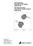
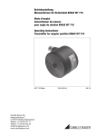
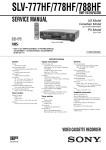
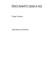
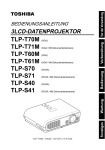
Betriebsanleitung
Messumformer für Stellung
KINAX SR 709
Operating Instructions
Transmitter for Position Feedback
KINAX SR 709
SR 709 Bde
Camille Bauer AG
Aargauerstrasse 7
CH-5610 Wohlen/Switzerland
Telefon +41 56 618 21 11
Telefax +41 56 618 35 35
info@camillebauer.com
www.camillebauer.com
138 611-04
06.10
KINAX SR 709
Messumformer für Stellung
Stellungsmelder für Ventilanbau nach NAMUR
0102
Verwendung
II 2 G
Der Stellungs-Rückmelder KINAX SR 709 (Bilder 1 und 2) dient
zum Erfassen von Hüben an Ventilen, Drosselklappen, Schiebern
und anderen Stellgliedern und formt diese Messgrösse in einen
eingeprägten, dem Messwert proportionalen Gleichstrom um.
Der Stellungs-Rückmelder besteht aus einem KINAX DrehwinkelMessumformer und einem vorgeschalteten Getriebe, das einen
Weg in einen Drehwinkel 0 … 90° umsetzt. Beide Teile sind in
einem robusten Aluminiumguss-Gehäuse zusammengefasst,
dessen Form und Verbindungsteile zum Stellglied von der NAMUR
empfohlen wurden.
Merkmale / Nutzen
● Messeingang: Weg, Hub
Messgrösse
Weg, Hub
Messbereich-Grenzen
0 … 10 bis 0 … 140
Bild 1. Stellungs-Rückmelder KINAX SR 709, Anschlusshebel in
Ruhestellung nach unten gerichtet, entspricht Ausgangsstrom 0/4 mA.
● Einstellung des Messbereiches durch Verändern der Hebelübersetzung, Feinabgleich durch Potentiometer / Optimale Anpassung
der Messspannen an individuelle Bedürfnisse
● Messausgang: Gleichstromsignal (eingeprägt, 2-, 3- oder 4-Drahtanschluss)
● Kapazitives Abtastsystem / Verschleissfrei
● Anbaugerät im Feldgehäuse aus Aluminiumguss mit NAMUR-Anbausatz für Stellglieder
● Ist lieferbar in Zündschutzart «Eigensicherheit» Ex ia IIC T6 / Einsatz
innerhalb des explosionsgefährdeten Bereiches möglich (siehe «Tabelle
3: Angaben über Explosionsschutz»)
Beschreibung
Bild 3. Minimale Hubeinstellung am Anschlusshebel.
Camille Bauer
20
10
88
Bild 2. Stellungs-Rückmelder KINAX SR 709, Anschlusshebel in
Ruhestellung nach oben gerichtet, entspricht Ausgangsstrom 0/4 mA.
140
Der Abgriff des Ventil-Hubes erfolgt durch einen geschlitzten
Hebel. Die Anpassung an Hübe zwischen 10 und 140 mm wird
durch eine äussere Hebelübersetzung und durch eine innere Zahnradübersetzung erreicht. Die äussere Hebelübersetzung lässt sich
so einstellen, dass die innere Schaltachse bei vollem Hub einen
Drehwinkel von ca. 90° durchläuft. Für diesen Drehwinkel von 90°
ist der eingebaute Messumformer KINAX 3W2 ausgelegt.
Bild 4. Maximale Hubeinstellung am Anschlusshebel.
Datenblatt SR 709 Ld – 06.10
3
KINAX SR 709
Messumformer für Stellung
Tabelle 1:
Technische Daten
Messeingang
Messgrösse:
Weg, Hub
Messbereich-Grenzen:
0 … 10 bis 0 … 140 mm
Nennspannungen UN
Toleranz-Angaben
24 … 60 V DC/AC
DC – 15 … + 33%
AC ± 15%
85 … 230 V DC/AC
möglich nur bei der
Standard-Ausführung, Nicht Ex,
mit Galvanischer Trennung,
mit Allstrom-Netzteil
(DC und 45 … 400 Hz)
Messausgang
Ausgangsgrösse IA:
Eingeprägter Gleichstrom
proportional zum Messwert
Nullpunktvariation:
Ca. ± 5%
Endwertvariation:
Ca. + 5 / –30%
Strombegrenzung:
IA max. 40 mA
Normbereiche:
0…1 mA,
3- oder 4-Drahtanschluss
Leistungsaufnahme:
< 0,9 W bzw. < 1,8 VA
Hilfsenergieeinfluss:
≤ 0,1% innerhalb der zulässigen
Hilfsenergie-Toleranz
Nur Gleichspannung1:
12 … 33 V
(möglich bei der Standard-Ausführung, Nicht Ex, ohne Galvanische
Trennung)
0…5 mA,
3- oder 4-Drahtanschluss
12 … 30 V
(erforderlich bei der Ex-Ausführung,
Zündschutzart «Eigensicherheit»
Ex ia IIC T6, ohne Galvanische
Trennung)
0…10 mA,
3- oder 4-Drahtanschluss
4…20 mA, 2-Drahtanschluss oder
0…20 mA, 3- oder 4-Drahtanschluss
(durch Potentiometer einstellbar)
4…20 mA,
3- oder 4-Drahtanschluss
0…20 mA, 4-Drahtanschluss
Nicht-Normbereiche:
Aussenwiderstand (Bürde):
0…> 1,00 bis 0…< 20 mA
3- oder 4-Drahtanschluss
Rext max. [kΩ] =
12 V
IA [mA]
(bei Geräten mit DC/AC-Hilfsenergie
durch Allstrom-Netzteil, mit Galvanischer Trennung)
Rext max. [kΩ] =
IA [mA]
IA = Ausgangssignal-Endwert
Max. Stromaufnahme:
Ca. 5 mA + IA
Hilfsenergieeinfluss:
< 0,2% innerhalb der zulässigen
Hilfsenergie-Toleranz
Mechanische Belastbarkeit
Vibrationsbeständigkeit:
20 … 200 Hz,
10 g dauernd, 15 g während 2 h
200 … 500 Hz,
5 g dauernd, 10 g während 2 h
Schock:
3 ×50 g je 10 Stösse
in allen Richtungen
Gebrauchslage:
Beliebig
Gehäuseangaben
Werkstoff:
Metall (Alu)
Stopfbuchsen:
2 Stopfbuchsen PG 11 aus Metall
Zum Anschliessen der elektrischen Leitungen befinden sich in dem
Rückenteil (Haube) 4 Schraubklemmen und 1 Erdungsklemme.
< 0,3% p.p.
Genauigkeitsangaben
Linearitätsfehler:
10% p.p.
H [V] – 12 V
(bei Geräten mit DC-Hilfsenergie,
ohne Galvanische Trennung)
Restwelligkeit des
Ausgangsstromes:
Max. Restwelligkeit:
Die Schraubklemmen eignen sich für max. 1,5 mm2 Drahtquerschnitte und sind nach dem Entfernen des Deckels zugänglich.
≤ 0,5%
Rückenteil
(Haube)
Hilfsenergie H
Gleich- und
Wechselspannung:
Schraubklemmen
Nennspannungen und ToleranzAngaben siehe «Tabelle 1»
Deckel
Erdungsklemme
Stopfbuchsen
1
Gegen Falschpolung geschützt. Der niedrigste Spannungswert darf
12 V nicht unterschreiten.
4
Bild 5. KINAX SR 709 mit Schraubklemmen und Stopfbuchsen.
Datenblatt SR 709 Ld – 06.10
Camille Bauer
KINAX SR 709
Messumformer für Stellung
Befestigung:
Unmittelbare Befestigung
Stossspannungsfestigkeit:
1 kV, 1,2/50 μs, 0,5 Ws
IEC 255-4, Kl. II
Zul. Gleichtaktspannung:
100 V, 50 Hz
oder
Befestigung mit NAMUR-Anbausatz
(siehe Bilder 9 und 10)
Gewicht:
Umgebungsbedingungen
Ca. 1,1 kg
Vorschriften
Elektromagnetische
Verträglichkeit:
Die Normen DIN EN 50 081-2 und
DIN EN 50 082-2 werden eingehalten
Eigensicher:
Nach EN 60 079-11: 2007
Prüfspannung:
2,2 kVeff, 50 Hz, 1 Min.
zwischen…
… Hilfsenergie und Gehäuse
… Hilfsenergie und Messausgang
(bei DC/AC-Hilfsenergie, mit Galvanischer Trennung, mit AllstromNetzteil)
500 Veff, 50 Hz, 1 Min.
alle elektrischen Anschlüsse gegen
Gehäuse (bei DC-Hilfsenergie, ohne
Galvanische Trennung)
Gehäuseschutzart:
IP 54 nach EN 60 529
Klimatische Beanspruchung: Standard-Ausführung
Temperatur – 25 bis + 70 °C
Rel. Feuchte im Jahresmittel
≤ 90%
oder
Ausführung mit erhöhter Klimafestigkeit
Temperatur – 40 bis + 70 °C
Rel. Feuchte im Jahresmittel
≤ 95%
Ex-Ausführung
Temperatur
– 40 bis + 60 °C bei T6
bzw. – 40 bis + 75 °C bei T5
Rel. Feuchte im Jahresmittel
≤ 95%
Betriebshöhe:
2000 m max.
Transport- und
Lagerungs-Temperatur:
– 40 bis 80 °C
Tabelle 2: Aufschlüsselung der Varianten
Bezeichnung
*Sperrcode
KINAX SR 709
Bestell-Code 709 - xxxx xx
unmöglich
bei Sperrcode
Artikel-Nr./
Merkmal
709 –
Merkmale, Varianten
1. Ausführung
Standard, Messausgang nicht eigensicher
A
1
Ex ia IIC T6, Messausgang eigensicher, ATEX
B
2
Ex ia IIC T6, Messausgang eigensicher, FTZU Tschechien
B
6
EEx ia IIC T6, Messausgang eigensicher, Ungarn
B
7
Sonstige Ausführungen auf Anfrage
B
9
2. Montagelage
Lage des Hebels bei Ruhestellung:
Unten, enspricht 0/4 mA (normal)
0
Oben, entspricht 0/4 mA
1
Nachträgliche Änderung nicht möglich!
Camille Bauer
Datenblatt SR 709 Ld – 06.10
5
KINAX SR 709
Messumformer für Stellung
Bezeichnung
KINAX SR 709
*Sperrcode
unmöglich
bei Sperrcode
Artikel-Nr./
Merkmal
Bestell-Code 709 - xxxx xx
709 –
Merkmale, Varianten
3. Ausgangssignal (Messausgang)
0 … 1 mA / 3- oder 4-Drahtanschluss
A
0 … 5 mA / 3- oder 4-Drahtanschluss
B
0 … 10 mA / 3- oder 4-Drahtanschluss
C
4 … 20 mA / 2-Drahtanschluss oder
0 … 20 mA / 3- oder 4-Drahtanschluss (mit Potentiometer einstellbar)
C
D
4 … 20 mA / 3- oder 4-Drahtanschluss
E
0 … 20 mA / 4-Drahtanschluss
Nur in Ausführung Standard mit DC/AC-Hilfsenergie (Allstrom-Netzteil)
D
B
F
Nichtnorm, 3- oder 4-Drahtanschluss
0 … > 1,00 bis 0 … < 20
[mA]
Z
Hilfsenergie DC/AC mit Galvanischer Trennung,
zwingend mit 4-Drahtanschluss,
DC-Hilfsenergie ohne Galvanische Trennung,
mit (2-), 3- oder 4-Drahtanschluss.
Bei 2-Drahtanschluss nur Zeile D möglich, kombiniert mit
Hilfsenergie 12 … 33 (30) V DC!
4. Hilfsenergie
24 … 60 V DC/AC, mit Galvanischer Trennung, mit Allstrom-Netzteil
E
BC
1
85 … 230 V DC/AC, mit Galvanischer Trennung, mit Allstrom-Netzteil
E
BC
2
12 … 33 V DC, ohne Galvanische Trennung
F
BD
A
12 … 30 V DC (Ex), ohne Galvanische Trennung
F
AD
B
Zeilen 1, 2 und A nur bei Ausführung Standard
Zeilen 1 und 2: DC/AC-Hilfsenergie bei Ausgangssignal «Auswahl-Kriterium 3,
Zeile D» nicht möglich!
5. Klimatische Beanspruchung
Normale Klimafestigkeit
0
Erhöhte Klimafestigkeit bei der Standard-Ausführung,
ohne Galvanische Trennung
Temperatur – 40 bis + 70 °C,
relative Feuchte im Jahresmittel ≤ 95% statt ≤ 90%
BE
1
Erhöhte Klimafestigkeit bei der Standard-Ausführung,
mit Galvanischer Trennung, mit Allstrom-Netzteil
Temperatur – 40 bis + 70 °C,
relative Feuchte im Jahresmittel ≤ 95% statt ≤ 90%
BF
2
Erhöhte Klimafestigkeit bei der Ex-Ausführung,
ohne Galvanische Trennung
Temperatur – 40 bis + 60 °C bei T6 bzw. – 40 bis + 75 °C bei T5,
relative Feuchte im Jahresmittel ≤ 95% statt ≤ 90%
AE
3
6. Anbausatz
Ohne Anbausatz
0
Mit NAMUR-Anbausatz Nr. 866 288
1
* Zeilen mit Buchstaben unter «unmöglich» sind nicht kombinierbar mit vorgängigen Zeilen mit gleichem Buchstaben unter «Sperrcode».
6
Datenblatt SR 709 Ld – 06.10
Camille Bauer
KINAX SR 709
Messumformer für Stellung
Tabelle 3: Angaben über Explosionsschutz
II 2 G
Zündschutzart «Eigensicherheit»
Kennzeichen
Gerät
Messausgang
Bestell-Code
SR 709 - 2 mit
eingebautem
KINAX 3W2
708 - 2
SR 709 - 6 mit
eingebautem
KINAX 3W2
708 - 6
SR 709 - 7 mit
eingebautem
KINAX 3W2
708 - 7
Baumusterprüfbescheinigung
ZELM 10 ATEX 0427 X
Ex ia IIC T6
Ex ia IIC T6
Montageort
des Gerätes
Bescheinigungen
= 30 V
= 160 mA
=1W
= 10 nF
=0
Ui
Ii
Pi
Ci
Li
Innerhalb
des explosionsgefährdeten Bereiches
Tschechien
FTZU 98 Ex 0280
Ungarn
BKI Nr. Ex-98.C.535 X
Ex ia IIC T6
Elektrische Anschlüsse
2-, 3- oder 4-Drahtanschluss ohne Galvanische Trennung
4-Drahtanschluss mit Galvanischer Trennung, mit AllstromNetzteil
–
A
A und H
+
H
3-Drahtanschluss
(diverse mA-Signale)
2-Drahtanschluss
(4 … 20 mA)
–
+
21
–
+
+
21
21
–
–
–
+
= Messausgang
H
= AC/DC-Hilfsenergie
Rext
Rext
+
A
Rext = Aussenwiderstand
+
+
Rext
–
43
43
43
–
+
+
–
Brücke
A
+
–
~ ~
H
+
+
–
43
21
–
4-Drahtanschluss
(diverse mA-Signale)
A
= Messausgang
als 2-Drahtanschluss
(4…20 mA, Signal im
Mess-Speise-Kreis)
als 3- oder 4-Drahtanschluss (diverse
mA-Signale)
H
+
Rext
–
+
A
–
H
4-Drahtanschluss
(diverse mA-Signale)
Camille Bauer
= DC-Hilfsenergie
H = 12 … 33 V
bzw. H = 12 … 30 V
bei Ex-Ausführung
Rext = Aussenwiderstand
Normales Zubehör
1 Betriebsanleitung, dreisprachig: Deutsch, Französisch,
Englisch
1 Ex-Bescheinigung, nur bei Geräten in Ex-Ausführung
Datenblatt SR 709 Ld – 06.10
7
KINAX SR 709
Messumformer für Stellung
Messumformer mit dem Bestell-Code 709 – ..D (siehe «Tabelle
2: Aufschlüsselung der Varianten») sind sowohl für den 2-Drahtanschluss mit dem Ausgangsstrom 4…20 mA als auch für den
3- bzw. 4-Drahtanschluss mit dem Ausgangsstrom 0…20 mA
geeignet.
Einstell-Elemente
Zero
Bei einem allfälligen Wechsel im Anschliessen des Gerätes (siehe
«Elektrische Anschlüsse») müssen jedoch Anfangs- und Endwert
des Messbereiches, ZERO und SPAN, neu eingestellt werden.
Span
S1
Bild 6.
ZERO
SPAN
S1
Lage der Einstell-Elemente.
= Potentiometer für Nullpunkt
= Potentiometer für Messbereich-Endwert
= Nicht eingebaut
Mass-Skizzen
98
105
M6
70°
8,1
25
+0
,
0 1
90
104
70
15,5
130
PG 11
14
18
2
31
Bild 7. KINAX SR 709, Lage des Anschlusshebels bei Ruhestellung nach unten gerichtet, entspricht Ausgangsstrom 0/4 mA.
8
Datenblatt SR 709 Ld – 06.10
Camille Bauer
KINAX SR 709
Messumformer für Stellung
98
8,1
25
+0
,
0 1
105
90
70°
104
70
M6
15,5
130
PG 11
31
18
2
14
Bild 8. KINAX SR 709, Lage des Anschlusshebels bei Ruhestellung nach oben gerichtet, entspricht Ausgangsstrom 0/4 mA.
2 Befestigungsbügel
oder
Schraube M8
Ø
–
35
70
20
90
Anbaulasche
Bild 9. KINAX SR 709, Anbau nach NAMUR-Empfehlung.
Camille Bauer
Datenblatt SR 709 Ld – 06.10
9
KINAX SR 709
Messumformer für Stellung
105
32
43
Ø
–3
43
20
6,5
20
13
90
130
48
5
9
80
90
4
12
Bild 10. NAMUR-Anbausatz.
Auf uns ist Verlass.
Camille Bauer AG
Aargauerstrasse 7
CH-5610 Wohlen / Schweiz
Telefon: +41 56 618 21 11
Telefax: +41 56 618 35 35
info@camillebauer.com
www.camillebauer.com
Änderungen vorbehalten • Ausgabe 06.10 • Datenblatt SR 709 Ld
Sicherheitshinweise, die unbedingt beachtet werden müssen, sind
in dieser Betriebsanleitung mit folgendenden Symbolen markiert:
Geräte dürfen nur fachgerecht entsorgt werden!
Betriebsanleitung
Messumformer
für Drehwinkel
KINAX 3W2
Camille Bauer AG
Aargauerstrasse 7
CH-5610 Wohlen/Switzerland
Telefon +41 56 618 21 11
Telefax +41 56 618 35 35
e-mail: info@camillebauer.com
http://www.camillebauer.com
57-3W2 Bd
993 304-03
06.10
Inhaltsverzeichnis
1. Erst lesen, dann … ...................................................................................... 1
2. Kurzbeschreibung ........................................................................................ 1
3. Lieferumfang ................................................................................................ 1
4. Aufschlüsselung der Varianten ..................................................................... 1
5. Technische Daten ......................................................................................... 2
6. Montage ....................................................................................................... 2
7. Elektrische Anschlüsse................................................................................. 3
8. Anfangs- und Endwert des Messbereiches einstellen ................................. 3
9. Umstellung von 2-Drahtanschluss
in 3- bzw. 4-Drahtanschluss oder umgekehrt .............................................. 3
10. Drehrichtung umkehren bei Geräten mit Messbereichen > 150
° ........... 3
KINAX 3W2 mit
Spezial-Antriebswelle
vorn und hinten.
Vorn: Ø 2 mm,
Länge 12 mm.
Hinten: Ø 2 mm,
Länge 6 mm.
KINAX 3W2 mit
Spezial-Antriebswelle
vorn und hinten.
Vorn: Ø 6 mm,
Länge 12 mm.
Hinten: Ø 2 mm,
Länge 6 mm.
KINAX 3W2 mit
Spezial-Antriebswelle
vorn und hinten.
Vorn: Ø 1/4˝,
Länge 12 mm.
Hinten: Ø 2 mm,
Länge 6 mm.
Bild 1
11. Mass-Skizzen ............................................................................................... 4
12. Konformitätserklärung .................................................................................. 4
1. Erst lesen, dann …
Der einwandfreie und gefahrlose Betrieb setzt voraus, dass die
Betriebsanleitung gelesen und die in den Abschnitten
6. Montage
7. Elektrische Anschlüsse
enthaltenen Sicherheitshinweise beachtet werden.
Bei einem Eingriff in das Gerät erlischt der Garantieanspruch!
Der Umgang mit diesem Gerät sollte nur durch entsprechend geschultes Personal
erfolgen, das das Gerät kennt und berechtigt ist, Arbeiten in regeltechnischen
Anlagen auszuführen.
Bild 2
4. Aufschlüsselung der Varianten
2. Kurzbeschreibung
Der Messumformer KINAX 3W2 erfasst kontaktlos die Winkelstellung einer Welle und
formt sie in einen eingeprägten, dem Messwert proportionalen Gleichstrom um.
Ausführungen in Zündschutzart «Eigensicherheit Ex ia IIC T6» mit eigensicherem
Messausgang ergänzen die Baureihe des Messumformers.
Erklärung der Bestell-Ziffern 1. bis 4.
Beschreibung
1.
3. Lieferumfang
Messumformer, eine der sechs Varianten (Bild 1)
3 Spannklammern (Bild 2)
Je 1 Betriebsanleitung (Bild 3) in Deutsch, Französisch und Englisch
1 Ex-Bescheinigung (Bild 3), nur bei Geräten in Ex-Ausführung
2.
KINAX 3W2 mit
Standard-Antriebswelle
nur vorn,
Ø 2 mm, Länge 6 mm.
KINAX 3W2 mit
Spezial-Antriebswelle
nur vorn,
Ø 6 mm, Länge 12 mm.
Bild 3
KINAX 3W2 mit
Spezial-Antriebswelle
nur vorn,
Ø 1/4˝, Länge 12 mm.
Bestell-Code
Ausführung des Messumformers
(mit Standard-Antriebswelle nur vorn,
Ø 2 mm, Länge 6 mm, siehe «Anmerkung»
708-
Standard, Messausgang nicht eigensicher
1
Ex ia IIC T6,
Messausgang eigensicher
ATEX
2
Kundenbezogen,
Messausgang eigensicher
(Japan)
(auf Anfrage)
5
Ex ia IIC T6,
Messausgang eigensicher
FTZU
(Tschechien)
6
EEx ia IIC T6
Messausgang eigensicher
BKI (Ungarn)
7
Drehrichtung
Kalibriert für Drehrichtung Uhrzeigersinn
1
Kalibriert für Drehrichtung Gegenuhrzeigersinn
2
V-Kennlinie
3
Kalibriert für Drehrichtung beidseitig und markiert
4
11
Beschreibung
3.
Bestell-Code
Vibrationsbeständigkeit:
5 g je 2 h in 3 Richtungen
f ≤ 200 Hz
Schock:
3 ×50 g je 10 Stösse
in allen Richtungen
Messbereich (Messeingang)
°
1
0 … 30
°
2
0 … 60
°
3
0 … 90
°
4
0 … 10
0 … 180
0 … 270
Zulässige statische
Belastung der Welle:
Antriebswellen Ø
Richtung
2 mm
5
°
6
°
Nichtnorm 0 … ≥ 5 bis 0 … < 270
6 mm bzw. 1/4˝
radial max.
16 N
83 N
axial max.
25 N
130 N
9
°
V-Kennlinie
4.
Mechanische Belastbarkeit
Gebrauchslage:
A
Ausgangssignal (Messausgang)
/ Anschlussart
(Hilfsenergie 12 … 33 V DC
bzw. 12 … 30 V DC bei Ex-Ausführung
Beliebig
Vorschriften
0 … 1 mA / 3- oder 4-Drahtanschluss
A
0 … 5 mA / 3- oder 4-Drahtanschluss
B
0 … 10 mA / 3- oder 4-Drahtanschluss
C
4 … 20 mA / 2-Drahtanschluss oder
0 … 20 mA / 3- oder 4-Drahtanschluss
D
4 … 20 mA / 3- oder 4-Drahtanschluss
E
Nichtnorm / 3- oder 4-Drahtanschluss
0 … > 1,00 bis 0 … < 20 mA
Z
Prüfspannung:
500 Veff, 50 Hz, 1 Min.
alle elektrischen Anschlüsse gegen Gehäuse
Gehäuseschutzart:
IP 50 nach EN 60 529
Umgebungsbedingungen
Klimatische Beanspruchung: Standard-Ausführung
Temperatur – 25 bis + 70 °C
Rel. Feuchte im Jahresmittel ≤ 90%
oder
Ausführung mit erhöhter Klimafestigkeit
Temperatur – 40 bis + 70 °C
Rel. Feuchte im Jahresmittel ≤ 95%
Ex-Ausführung
Temperatur – 40 bis + 60 °C bei T6
bzw. – 40 bis + 75 °C bei T5
Anmerkung: Die noch weiter festgelegten Bestell-Ziffern befassen sich mit Besonderheiten, u.a. mit Spezial-Antriebswellen, vgl. Bild 1.
5. Technische Daten
Betriebshöhe:
2000 m max.
Transport- und
Lagerungs-Temperatur:
– 40 bis 80 °C
Messeingang
1
°
Vorzugsbereiche
0…10, 0…30, 0…60, 0…90,
°
0…180 oder 0…270
6. Montage
Messausgang
Normbereiche:
0…1 mA, 3- oder 4-Drahtanschluss
0…5 mA, 3- oder 4-Drahtanschluss
0…10 mA, 3- oder 4-Drahtanschluss
4…20 mA, 2-Drahtanschluss
oder
0…20 mA, 3- oder 4-Drahtanschluss durch Potentiometer einstellbar
4…20 mA, 3- oder 4-Drahtanschluss
Aussenwiderstand (Bürde):
Alle sechs Messumformer-Varianten (Bild 1), die sich äusserlich durch die Ausführung der Antriebswellen unterscheiden, lassen sich entweder unmittelbar oder
mit 3 Spannklammern am Messobjekt montieren. Beide Montagearten und die
zugehörigen Bohr-Ausschnitts-Pläne sind Inhalt der Tabelle 1.
Tabelle 1:
Montagearten2
Ø 3,2
M3
4,5 tief
0…> 1,00 bis 0…< 20 mA
3- oder 4-Drahtanschluss
Rext max. [kΩ] =
Bohr-Ausschnitts-Pläne für
Anbauteil (am Messobjekt)
0°
Eingeprägter Gleichstrom, proportional zum Drehwinkel
12
Ausgangsgrösse IA:
Nicht-Normbereiche:
Gegen Falschpolung geschützt. Der niedrigste Spannungswert darf 12 V nicht
unterschreiten.
30 ±0,1
0…≥ 5 bis 0… ≤ 270
unmittelbar
Messbereiche:
H [V] – 12 V
IA [mA]
+ 0,021
20 + 0
H = Hilfsenergie
IA = Endwert der Ausgangsgrösse
Grundgenauigkeit:
Fehlergrenze ≤ 0,5% für Bereiche 0…≤ 150
°
Fehlergrenze ≤ 1,5% für Bereiche von 0…> 150 bis
0…270
°
Hilfsenergie H
Gleichspannung1:
10% p.p.
Max. Stromaufnahme:
ca. 5 mA + IA
Werkstoff
12
+ 0,025
40 + 0
12…33 V
(möglich bei der Standard-Ausführung, Nicht Ex)
12…30 V
(erforderlich bei der Ex-Ausführung, Zündschutzart
Eigensicherheit Ex ia IIC T6)
Max. Restwelligkeit:
Gehäuse (Grundteil):
65 ±0,1
Messbereich
°
Bezugswert:
0
12
mit 3 Spannklammern
M4
Genauigkeitsangaben
Metall (Alu)
Oberfläche chromatisiert
2
gezeigt am KINAX 3W2 mit Standard-Antriebswelle nur vorn, ∅ 2 mm, Länge 6 mm.
Die «unmittelbare» Montageart verlangt 3 Schrauben M3, wohingegen die «mit
Spannklammern» 3 Schrauben M4 erfordert. Die Schrauben gehören nicht zum
Lieferumfang, da ihre Längen durch die von Fall zu Fall schwankende Dicke des
Anbauteils am Messobjekt bestimmt werden.
Bei der Festlegung des Montageortes (Messortes) ist zu berücksichtigen, dass die Angaben unter «Umgebungsbedingungen»,
Abschnitt «5. Technische Daten», eingehalten werden.
Anbauteil (am Messobjekt) mit Ausschnitt und Durchgangslöchern nach dem
zutreffenden Bohr-Ausschnitts-Plan «Tabelle 1» versehen. Danach den Messumformer montieren.
Brücke
OU
T
Beim Festziehen und Ausrichten ist darauf zu achten, dass die Lage
des Messumformer-Nullpunktes und die Nullstellung des Messobjektes übereinstimmen.
+
V
–
Rext.
Diese Deckungsgleichheit lässt sich durch Drehen des Messumformers
erreichen.
OU
T
–
+
+
V
Rext. +
A
OU
T
–
+
V
Rext. +
–
A
–
Daher wird bei der «unmittelbaren» Montageart empfohlen, die
3 Durchgangslöcher (3,2 mm Ø) als Langlöcher auszuführen.
+ –
+ –
+ –
A und H
H
H
Die Montageart «mit Spannklammern» bietet offensichtlich die
Möglichkeit, den Messumformer zu drehen.
2-Drahtanschluss
(4…20 mA)
Der elektrische Nullpunkt wird bei Drehwinkel-Messumformern mit
Bereichen 0 bis …
° sowohl auf der Vorderseite als auch auf der Rückseite markiert (vgl. obere Abbildung). Er ist dagegen bei Winkeltransmittern mit V-Kennlinien und bei Geräten mit Drehrichtung beidseitig
nur auf der Vorderseite angebracht (vgl. untere Abbildung).
Vorderseite
Rückseite
(1)
(1)
(2)
(2)
H
Rext.
3-Drahtanschluss
(diverse mA-Signale)
4-Drahtanschluss
(diverse mA-Signale)
= Messausgang …
… als 2-Drahtanschluss (4…20 mA, Signal im Mess-Speise-Kreis)
… als 3- oder 4-Drahtanschluss (diverse mA-Signale)
= DC-Hilfsenergie H = 12…33 V bzw. H = 12…30 V bei Ex-Ausführung
= Aussenwiderstand
Bild 6. Anschlusspläne für 2-, 3- oder 4-Drahtanschluss.
ZERO
SPAN
S1
OU
T
+
V
8. Anfangs- und Endwert des
Messbereiches einstellen
–
(1)
(2)
A
–
(1) = Nullpunkt-Markierung auf
dem Gehäuse
(2) = Nullpunkt-Markierung auf der
Scheibe der Antriebswelle
Die «grobe» Einstellung des Messbereich-Anfangswertes, die darin besteht,
die Nullstellung des Messobjektes auf den äusserlich markierten Nullpunkt des
Messumformers auszurichten, wurde bereits unter «6. Montage» beschrieben.
In diesem Abschnitt wird dagegen die genaue Einstellung, der Feinabgleich,
sowohl des Anfangswertes (Nullpunkt/ZERO) als auch des Endwertes (Spanne/
SPAN) behandelt.
Messumformer in Betrieb nehmen. Dazu einfach die Hilfsenergie einschalten.
7. Elektrische Anschlüsse
Zum Anschliessen der elektrischen Leitungen hat der Messumformer auf seiner
Rückseite 3 Lötstützpunkte (3), siehe Bild 4. Die Schutzart der Lötstützpunkte ist
IP 00 nach EN 60 529.
Die ZERO/SPAN-Dichtungsstopfen (4) herausziehen (Bild 7, links). Messobjekt in
Nullstellung bringen, d.h. in die Position, in der der KINAX 3W2 den Ausgangsstrom
0 mA (bei einem 3- oder 4-Drahtanschluss) bzw. 4 mA (bei dem 2-Drahtanschluss)
ausgeben soll.
Weicht der Ausgangsstrom mehr als 2% von seinem Anfangswert ab, dann zunächst
die «grobe» Nullpunkteinstellung, siehe Abschnitt «6. Montage», wiederholen.
Danach Potentiometer «ZERO» (Bild 7, rechts) mit einem Uhrmacher-Schraubenzieher
(Ø 2,3 mm) so drehen, dass genau der gewünschte Ausgangsstrom fliesst.
(3)
(4)
Bild 4
Es ist zu beachten, …
… dass die Daten, die zur Lösung der Messaufgabe erforderlich sind,
mit denen auf dem Typenschild (Bild 5) des KINAX 3W2 übereinstimmen (Range/Messeingang, Output/Messausgang, Supply
Voltage/Hilfsenergie)!
… dass der Gesamtwiderstand in der Messausgangsleitung (in
Serie geschaltete Empfangsgeräte plus Leitung) den maximalen
Aussenwiderstand Rext. max. nicht überschreitet! Rext. max. siehe
«Messausgang», Abschnitt «5. Technische Daten»!
… dass bei der Verlegung der Messausgangsleitung verdrillte Kabel
verwendet werden und diese möglichst getrennt von Starkstromleitungen zu verlegen sind!
Im übrigen landesübliche Vorschriften bei der Installation und Auswahl
des Materials der elektrischen Leitungen befolgen!
Bei Geräten in der Zündschutzart «Eigensicherheit» mit eigensicherem
Messausgang sind zusätzlich die Angaben der Ex-Bescheinigung sowie
die nationalen Vorschriften für die Errichtung von elektrischen Anlagen
in explosionsgefährdeten Bereichen zu berücksichtigen!
KINAX 3W2
Supply
Range: 0…30º
Type: 708-112D 0
Voltage
Output: 0/4…20 mA
Ord: 999/888888/776/997
12…33V Rotation Sense CW/CCW: >>
Camille Bauer AG
Aargauerstr. 7
CH-5610 Wohlen
Switzerland
Bild 5. Beispiel eines Typenschildes.
Leitungen anschliessen, dazu die einzelnen Adern nach dem jeweils zutreffenden
Anschlussplan (Bild 6) anlöten.
Lötstützpunkte (3) nicht überhitzen!
Möglichst kleinen Lötkolben verwenden!
Bild 7. Einstell-Elemente «ZERO», «SPAN» und «S1».
Links: Einstell-Elemente durch Dichtungsstopfen (4) abgedeckt.
Rechts: Einstell-Elemente zugänglich.
Sodann Messobjekt in Endlage drehen, d.h. in die Stellung, in der der KINAX 3W2
den ihm zugedachten Ausgangsstrom-Endwert, siehe Typenschild, haben soll.
Potentiometer «SPAN» mit dem erwähnten Schraubenzieher derart drehen, dass
genau der gewünschte Ausgangsstrom-Endwert abgegeben wird.
Danach wieder eine Kontrolle des Nullpunktes vornehmen, allenfalls mit dem
ZERO-Potentiometer korrigieren und nochmal den Endwert prüfen.
9. Umstellung von 2-Drahtanschluss
in 3- bzw. 4-Drahtanschluss oder
umgekehrt
Messumformer mit dem Bestell-Code 708 – ...D (siehe Abschnitt «4. Aufschlüsselung
der Varianten») sind sowohl für den 2-Drahtanschluss mit dem Ausgangsstrom
4…20 mA als auch für den 3- bzw. 4-Drahtanschluss mit dem Ausgangsstrom
0…20 mA geeignet.
Bei einem allfälligen Wechsel im Anschliessen des Gerätes (siehe Anschlusspläne
im Bild 6) müssen jedoch Anfangs- und Endwert des Messbereiches neu eingestellt werden.
10. Drehrichtung umkehren
bei Geräten mit Messbereichen > 150
°
Winkeltransmitter mit Messbereichen > 150
° haben für die Drehrichtungsumkehr einen Schalter, der mit S1 bezeichnet ist und auch durch eine Öffnung auf der
Rückseite betätigt werden kann (Bild 7).
Bei einer Richtungsumkehr den Dichtungsstopfen (4), der den Schalter S1 abdeckt, herausziehen. Sodann den Schalter mit dem Uhrmacher-Schraubenzieher
(Ø 2,3 mm) mit einer Vierteldrehung umschalten, und Anfangs- und Endwert des
Messbereiches neu einstellen.
13
14
Camille Bauer AG
Switzerland
Aargauerstrasse 7
CH-5610 Wohlen
Messumformer für Stellung
Transmitter for position feedback
Kinax SR 709
Hersteller/
Manufacturer:
Anschrift /
Address:
Produktbezeichnung/
Product name:
Typ / Type:
EN 55011 : 2007+A2:2007
IEC
IEC
IEC
IEC
IEC
IEC
EN 61000-6-2 : 2005
–0,005
–0,014
11
Ø6 g6 –0,012
–0,004
Ø6 g6
7
48
1
120°
11
26,1
7
26,1
Bild 13. KINAX 3W2 mit Spezial-Antriebswelle vorn und hinten.
Vorn: ∅ 1/4ʺ, Länge 12 mm. Hinten: ∅ 2 mm, Länge 6 mm.
12. Konformitätserklärung
Ø 40 f7
Ø2
Ø2
Ø1/4˝
–0,005
(6,35 g6) –0,014
Ø 40 f7
120°
Ø 20 f7
M3
4,5 tief
Ø 20 f7
1
Qualitätsmanager / Quality manager
– 0,008
– 0,014
J. Brem
48
Ø 40 f7
Ø 20 f7
30 ±0,1
11
Leiter Technik / Head of engineering
12
1
M. Ulrich
26,1
7
Unterschrift / signature:
120°
Wohlen, 12. August 2009
30 ±0,1
48
Ort, Datum /
Place, date:
30 ±0,1
12
The explosion protected variant of this product has been manufactured according the
European directive 94/9
M3
4,5 tief
IEC 61010-1: 2001
26,1
EN 61010-1: 2001
M3
4,5 tief
Die explosionsgeschützte Ausführung dieses Produkts stimmt mit der Europäischen
Richtlinie 94/9/EG überein.
Ø 40 f7
Ø 20 f7
30 ±0,1
11 6
EN/Norm/Standard IEC/Norm/Standard
2006/95/EC
E l e k t r i s c h e B e t r i e b s m i t t e l z u r V e r we n d u n g i n n e r h a l b b e s t i m m t e r S p a n n u n g s grenzen – Niederspannungsrichtlinie – CE-Kennzeichnung : 95
E l e c t r i c a l e q u i p m e n t f o r u s e wi t h i n c e r t a i n v o l t a g e l i m i t s – L o w V o l t a g e D i r e c tive – Attachment of CE marking : 95
Bild 12. KINAX 3W2 mit Spezial-Antriebswelle nur vorn,
∅ 1/4ʺ, Länge 12 mm.
R i c h t l i n i e / D i r e c t i ve
Bild 10. KINAX 3W2 mit Spezial-Antriebswelle nur vorn,
∅ 6 mm, Länge 12 mm.
2006/95/EG
Ø 40 f7
Bild 8. KINAX 3W2 mit Standard-Antriebswelle nur vorn,
Ø 2 mm, Länge 6 mm.
Nr. / No.
Ø1/4˝
(6,35 g6)
61000-4-2: 1995+A1:1998+A2:2001
61000-4-3: 2006+A1:2007
61000-4-4: 2004
61000-4-5: 2005
61000-4-6: 2008
61000-4-11: 2004
7
EN 61000-6-4 : 2007
11
Störaussendung /
Emission
Störfestigkeit /
Immunity
1
M e s s ve r f a h r e n /
Measurement methods
7
Fachgrundnorm /
Generic Standard
48
11
EMV /
EMC
120°
Ø 20 f7
Ø2
Ø 40 f7
120°
Ø 20 f7
1
Elektromagnetische Verträglichkeit - EMV-Richtlinie
Electromagnetic compatibility - EMC directive
48
R i c h t l i n i e / D i r e c t i ve
7
2004/108/EG
2004/108/EC
120°
Nr. / No.
30 ±0,1
1
The above mentioned product has been manufactured according to the regulations of the following European directives proven through compliance with the following standards:
30 ±0,1
48
Das bezeichnete Produkt stimmt mit den Vorschriften folgender Europäischer Richtlinien
überein, nachgewiesen durch die Einhaltung folgender Normen:
SR709_CE-konf.DOC
Dokument-Nr./
Document.No.:
EG - KONFORMITÄTSERKLÄRUNG
EC DECLARATION OF CONFORMITY
11. Mass-Skizzen
M3
4,5 tief
12
6
–0,008
–0,014
26,1
Bild 9. KINAX 3W2 mit Spezial-Antriebswelle vorn und hinten.
Vorn: Ø 2 mm, Länge 12 mm. Hinten: Ø 2 mm, Länge 6 mm.
M3
4,5 tief
12
6
Ø2
–0,004
–0,012
26,1
Bild 11. KINAX 3W2 mit Spezial-Antriebswelle vorn und hinten.
Vorn: ∅ 6 mm, Länge 12 mm. Hinten: ∅ 2 mm, Länge 6 mm.
M3
4,5 tief
12
6
KINAX SR 709
Transmitter for Position Feedback
Position transmitter with NAMUR valve fitting
0102
Application
II 2 G
The position feedback transmitter KINAX SR 709 (Fig. 1 and 2)
is used to measure and transmit linear displacement (stroke) on
various types of control valves and other control devices. The
output is a load independent DC signal. The position feedback
transmitter consists of a KINAX angle transmitter and a reduction
gear which converts a linear movement into an angle of rotation of
0 … 90°. Both parts are contained in a robust cast aluminium
housing. The mounting part to the control valve is based on
NAMUR recommendations, (standards working group for measuring and process control in the chemical industry).
Features / Benefits
● Measuring input: Movement, stroke
Measured variable
Movement, stroke
Measuring range limits
0 … 10 to 0 … 140
Fig. 1. Position feedback transmitter KINAX SR 709 showing the
operating lever in the lower zero position, corresponding output
current 0/4 mA.
● Setting of the measuring range is achieved via adjusting the lever
system pivot point. More precise calibration is via zero and span
potentiometers / Optimum adjustment of zero and span can be made
to meet individual requirements
● Measuring output: DC current signal (load-independent, 2, 3 or 4-wire
connection)
● Capacitive scanning system / Non-wearing
● Unit in field type housing in cast aluminium with NAMUR mounting
part for fitting to control valve
● Available in type of protection “Intrinsic safety” Ex ia IIC T6 / Can be
mounted within the hazardous area (see “Table 3: Data on explosion
protection”)
Description
Fig. 3. Operating lever set for minimum operating angle.
15
88
140
Fig. 2. Position feedback transmitter KINAX SR 709 showing the
operating lever in the upper zero position, corresponding output
current 0/4 mA.
20
10
The pick-up of the stroke movement is made by means of a
slotted lever. The adaption to strokes between 10 and 140 mm is
made with an external lever transmission and by an internal gear
ratio. The external lever transmission can be adjusted in such a
way, that the internal cam shaft makes an angle of rotation of
approx. 90° for a full stroke. The measuring range of the built-in
angle transmitter KINAX 3W2 then corresponds with this angular
rotation of 90°.
Fig. 4. Operating lever set for maximum operating angle.
Data sheet SR 709 Le – 06.10
Camille Bauer
KINAX SR 709
KINAX SR 709
Messumformer für Stellung Transmitter for Position Feedback
Table 1:
Technical data
Measuring input
Measured variable:
Movement, stroke
Measuring range limits:
0 … 10 to 0 … 140 mm
Nominal voltages UN
Tolerances
24 … 60 V DC/AC
DC – 15 … + 33%
AC ± 15%
85 … 230 V DC/AC
only possible with
standard version, non-Ex,
with electric isolation,
with AC/DC power pack
(DC and 45 … 400 Hz)
Measuring output
Output variable IA:
Load-independent DC current,
proportional to the input angle
Zero point correction:
Approx. ± 5%
Span adjustment:
Approx. + 5 / –30%
Current limitation:
IA max. 40 mA
Standard ranges:
0…1 mA,
3 or 4-wire connection
Power consumption:
< 0.9 W resp. < 1.8 VA
Power supply effect
on accuracy:
≤ 0.1% within the admissible power
supply tolerance
DC voltage only1:
12 … 33 V
(possible with standard version,
non-Ex, without electric isolation)
0…5 mA,
3 or 4-wire connection
12 … 30 V
(necessary with Ex version,
type of protection “Intrinsic safety”
Ex ia IIC T6, without electric isolation)
0…10 mA,
3 or 4-wire connection
4…20 mA, 2-wire connection or
0…20 mA, 3 or 4-wire connection
(adjustable with potentiometer)
4…20 mA,
3 or 4-wire connection
0…20 mA, 4-wire connection
Non-standard ranges:
External resistance (load):
0…> 1.00 to 0…< 20 mA
3 or 4-wire connection
Rext max. [kΩ] =
12 V
IA [mA]
IA = Output signal end value
Approx. 5 mA + IA
Power supply effect
on accuracy:
Mechanical withstand
Permissible vibration:
20 … 200 Hz,
10 g continuous, 15 g for 2 h
200 … 500 Hz,
5 g continuous, 10 g for 2 h
Shock:
3 ×50 g every 10 impulses
in all 3 axes
Mounting position:
Any
Housing data
Material:
Metal (aluminium)
Cable glands:
2 cable glands PG 11 in metal
The screw terminals accept gauges up to 1.5 mm2 and are
accessible after removing the cover.
≤ 0.5%
Rear
(cover)
Power supply H
DC und AC voltage:
< 0.2% within the admissible power
supply tolerance
There are 4 screw terminals and a grounding terminal in the rear
cover for connecting the electrical leads.
< 0.3% p.p.
Accuracy
Linearity error:
Max. current consumption:
H [V] – 12 V
(for instruments with DC power
supply, without electric isolation)
Residual ripple in
output current:
10% p.p.
IA [mA]
(for instruments with DC/AC power
supply by AC/DC power pack, with
electric isolation)
Rext max. [kΩ] =
Max. residual ripple:
Nominal voltages and tolerances see
“Table 1”
Screw terminals
Cover
Ground terminal
Cable glands
1
Polarity reversal protection. The voltage must not fall below 12 V.
16
Fig. 5. KINAX SR 709 with screw terminals and cable glands.
Datenblatt
Data
sheet SR
SR 709
709 Ld
Le – 06.10
Camille Bauer
KINAX SR 709
KINAX SR 709
Transmitter for Position Feedback Messumformer für Stellung
Mounting:
Directly
Impulse voltage withstand:
or
Weight:
Fixing with NAMUR mounting part
(see Fig. 9 and 10)
Permissible commonmode voltage:
Approx. 1.1 kg
Environmental conditions
Electromagnetic
compatibility:
Standard version
Temperature – 25 to + 70 °C
Annual mean relative humidity
≤ 90%
The standards DIN EN 50 081-2 and
DIN EN 50 082-2 are observed
Intrinsically safe:
Acc. to EN 60 079-11: 2007
Test voltage:
2.2 kVeff, 50 Hz, 1 min.
between…
… power supply and housing
… power supply and measuring
output
(with DC/AC power supply, with
electric isolation, with AC/DC power
pack)
500 Veff, 50 Hz, 1 min.
all electric connections to housing
(with DC power supply, without
electric isolation)
Housing protection:
100 V, 50 Hz
Climatic rating:
Regulations
IP 54 acc. to EN 60 529
1 kV, 1.2/50 μs, 0.5 Ws
IEC 255-4, Cl. II
or
Version with improved climatic
rating
Temperature – 40 to + 70 °C
Annual mean relative humidity
≤ 95%
Ex version
Temperature
– 40 to + 60 °C at T6
resp. – 40 to + 75 °C at T5
Annual mean relative humidity
≤ 95%
Altitude:
2000 m max.
Transportation and
storage temperature:
– 40 to 80 °C
Table 2: Specification and ordering information
*Blocking
Code
Description
KINAX SR 709
Order Code 709 - xxxx xx
No-go with
Article No./
blocking code
Feature
709 –
Features, Selection
1. Version
Standard, measuring output non intrinsically safe
A
1
Ex ia IIC T6, measuring output intrinsically safe, ATEX
B
2
Ex ia IIC T6, measuring output intrinsically safe, FTZU Czech republic
B
6
EEx ia IIC T6, measuring output intrinsically safe, Hungary
B
7
Other versions on request
B
9
2. Mounting position
Lever in spring loaded position:
Lower end position corresponding to 0/4 mA (normal)
0
Upper end position corresponding 0/4 mA
1
Later changes not possible!
17
Camille
Bauer
Data
sheet SR
SR 709
709 Ld
Le – 06.10
Datenblatt
Camille Bauer
17
KINAX SR 709
KINAX SR 709
Messumformer für Stellung Transmitter for Position Feedback
*Blocking
Code
Description
KINAX SR 709
No-go with
Article No./
blocking code
Feature
Order Code 709 - xxxx xx
709 –
Features, Selection
3. Output signal (measuring output)
0 … 1 mA / 3 or 4-wire connection
A
0 … 5 mA / 3 or 4-wire connection
B
0 … 10 mA / 3 or 4-wire connection
C
4 … 20 mA / 2-wire connection or
0 … 20 mA / 3 or 4-wire connection (adjustable with potentiometer)
C
D
4 … 20 mA / 3 or 4-wire connection
E
0 … 20 mA / 4-wire connection
DC/AC power supply only (AC/DC power supply)
D
B
F
Non-standard, 3 or 4-wire connection
0 … > 1.00 to 0 … < 20
[mA]
Z
DC/AC electrically insulated power supply only for 4-wire connection,
DC non-electrically insulated power supply for (2), 3 or 4-wire connection.
Only line D is possible for 2-wire connection in conjunction with power supply
voltage 12 … 33 (30) V DC!
4. Power supply
24 … 60 V DC/AC, with electric isolation, with AC/DC power supply
E
BC
1
85 … 230 V DC/AC, with electric isolation, with AC/DC power supply
E
BC
2
12 … 33 V DC, without electric isolation
F
BD
A
12 … 30 V DC (Ex), without electric isolation
F
AD
B
Lines 1, 2 and A for standard version only
Lines 1 and 2: Power supply DC/AC not possible with output signal “Feature 3,
line D”!
5. Climatic rating
Standard climatic rating
0
Improved climatic rating at standard version,
without electric isolation
Temperature – 40 to + 70 °C,
annual mean relative humidity ≤ 95% instead of ≤ 90%
BE
1
Improved climatic rating at standard version,
with electric isolation, with AC/DC power supply
Temperature – 40 to + 70 °C,
annual mean relative humidity ≤ 95% instead of ≤ 90%
BF
2
improved climatic rating at Ex version,
without electric isolation
Temperature – 40 to + 60 °C at T6 resp. – 40 to + 75 °C at T5,
annual mean relative humidity ≤ 95% instead of ≤ 90%
AE
3
6. Mounting set
Without mounting set
0
With mounting set No. 866 288
1
* Lines with letter(s) under “No-go” cannot be combined with preceding lines having the same letter under “Blocking code”.
18
Datenblatt
Data
sheet SR
SR 709
709 Ld
Le – 06.10
Camille Bauer
KINAX SR 709
KINAX SR 709
Transmitter for Position Feedback Messumformer für Stellung
Table 3: Data on explosion protection
II 2 G
Type of protection «Intrinsically safe»
Marking
Instrument
Measuring output
Order Code
SR 709 - 2
with built-in
KINAX 3W2
708 - 2
SR 709 - 6
with built-in
KINAX 3W2
708 - 6
SR 709 - 7
with built-in
KINAX 3W2
708 - 7
Type Examination Certificate
ZELM 10 ATEX 0427 X
Ex ia IIC T6
Ex ia IIC T6
Mounting location
of device
Certificates
= 30 V
= 160 mA
=1W
= 10 nF
=0
Ui
Ii
Pi
Ci
Li
Czech republic
FTZU 98 Ex 0280
Within
the hazardous area
Hungary
BKI Nr. Ex-98.C.535 X
Ex ia IIC T6
Electrical connections
4-wire connection and electrically insulated AC/DC power
supply
Non-electrically insulated 2, 3 or 4-wire connection
–
A
A and H
+
H
3-wire connection
(different mA-signals)
2-wire connection
(4 … 20 mA)
–
+
21
–
+
+
21
21
–
–
–
+
= Measuring output
H
= AC/DC power supply
Rext
Rext
+
A
Rext = External resistance
+
+
Rext
–
43
43
43
–
+
+
–
Jumper
A
+
–
~ ~
H
+
+
–
43
21
–
4-wire connection
(different mA-signals)
A
= Measuring output
as 2-wire connection
(4…20 mA, signal in
output/powering)
as 3 or 4-wire
connection (different
mA-signals)
H
+
Rext
–
+
A
–
H
4-wire connection
(different mA-signals)
19
Camille
Bauer
= DC power supply
H = 12 … 33 V
resp. H = 12 … 30 V
with Ex version
Rext = External resistance
Standard accessories
1 Operating Instructions in three languages: German, French,
English
1 Ex approval (for instruments in Ex version only)
Data
sheet SR
SR 709
709 Ld
Le – 06.10
Datenblatt
Camille Bauer
19
KINAX SR 709
Transmitter
for Position
Feedback
Messumformer
für Stellung
Transmitter with Ordering Code 709 – ..D (see «Table 2: Specification and ordering information”) can be used for a 2-wire connection
and an output current of 4…20 mA or for 3 and 4-wire connections
and an output current of 0…20 mA.
Settings
Zero
If the mode of connection is changed (see “Electrical connections»),
the beginning and end of the measuring range, i.e. ZERO and
SPAN, have to be recalibrated.
Span
S1
Fig. 6.
ZERO
SPAN
S1
Locations of the settings.
= Potentiometer for zero point
= Potentiometer for full-scale measuring range
= Not fitted
Dimensional drawings
98
105
M6
70°
8.1
25
+0
,
0 1
90
104
70
15.5
130
PG 11
14
18
2
31
Fig. 7. Position of the KINAX SR 709 operating lever in the lower zero position, corresponding output current 0/4 mA.
20
Datenblatt
Data
sheet SR
SR 709
709 Ld
Le – 06.10
Camille Bauer
KINAX SR 709
KINAX SR 709
Transmitter for Position Feedback Messumformer für Stellung
98
8.1
25
+0
,
0 1
105
90
70°
104
70
M6
15.5
130
PG 11
31
18
2
14
Fig. 8.Position of the KINAX SR 709 operating lever in the upper zero position, corresponding output current 0/4 mA.
2 shackles
or
M8 bolt
Ø
–
35
70
20
90
Mounting bracket
Fig. 9. KINAX SR 709 with fitting recommended by NAMUR.
21
Camille
Bauer
Data
sheet SR
SR 709
709 Ld
Le – 06.10
Datenblatt
Camille Bauer
21
KINAX SR 709
KINAX SR 709
Messumformer für Stellung Transmitter for Position Feedback
105
32
43
Ø
–3
43
20
6.5
20
13
90
130
48
5
9
80
90
4
12
Fig. 10. NAMUR mounting set.
Auf uns
ist Verlass.
Rely
on us.
AG
Camille Bauer Ltd
Aargauerstrasse 7
Schweiz
CH-5610 Wohlen / Switzerland
Telefon: +41
56 56
618618
21 21
11 11
Phone:
+41
Telefax: +41
56 56
618618
35 35
35 35
Fax:
+41
info@camillebauer.com
www.camillebauer.com
Subect
Änderungen
to change
vorbehalten
without •notice
Ausgabe
• Edition
06.1006.10
• Datenblatt
• Data SR
sheet
709
SRLd709 Le
Safety precautions to be strictly observed are marked with following
symbols in the Operating Instructions:
The instruments must only be disposed of in the
correct way!
Operating Instructions
Transmitter
for angular position
KINAX 3W2
Camille Bauer LTD
Aargauerstrasse 7
CH-5610 Wohlen/Switzerland
Phone +41 56 618 21 11
Fax +41 56 618 35 35
e-mail: info@camillebauer.com
http://www.camillebauer.com
57-3W2 Be
997 223-03
06.10
Contents
1. Read first and then … ................................................................................. 1
2. Brief description ........................................................................................... 1
3. Scope of supply ........................................................................................... 1
4. Specification and ordering information ........................................................ 1
5. Technical data .............................................................................................. 2
6. Mounting ...................................................................................................... 2
7. Electrical connections .................................................................................. 3
8. Setting the beginning and end of the measuring range ............................... 3
9. Adaptation from 2-wire connection to
3- or 4-wire connection and vice versa ........................................................ 3
10. Reverseing the rotation for instruments
° ............................................................... 3
with measuring ranges > 150
KINAX 3W2 with
special drive shaft
at front and rear.
At front: Ø 2 mm,
length 12 mm.
At rear: Ø 2 mm,
length 6 mm.
KINAX 3W2 with
special drive shaft
at front and rear.
At front: Ø 6 mm,
length 12 mm.
At rear: Ø 2 mm,
length 6 mm.
KINAX 3W2 with
special drive shaft
at front and rear.
At front: Ø 1/4˝,
length 12 mm.
At rear: Ø 2 mm,
length 6 mm.
Fig. 1
11. Dimensional drawings .................................................................................. 4
12. Declaration of conformity ............................................................................. 4
1. Read first and then …
The proper and safe operation of the device assumes that the
Operating Instructions are read carefully and the safety warnings given in the various Sections
6. Mounting
7. Electrical connections
are observed.
Unauthorized repair or alteration of the unit invalidates the warranty!
Fig. 2
Fig. 3
The device should only be handled by appropriately trained personnel who are
familiar with it and authorised to work in control technique installations.
4. Specification and ordering information
Significance of the digits 1. to 4.
2. Brief description
The KINAX 3W2 transmitter converts the angular position of a shaft into a load
independent direct current signal, proportional to the angular position.
Description
1.
Explosion-proof “Intrinsically safe Ex ia IIC T6” versions with I.S. measuring
output rounds off this series of transmitters.
3. Scope of supply
Transmitter, one of the six versions (Fig. 1)
3 clamps (Fig. 2)
1 ea. Operating Instructions (Fig. 3) in English, French, German
1 Ex approval (Fig. 3), only for Ex version devices
2.
KINAX 3W2 with
standard drive shaft
at front only,
Ø 2 mm, length 6 mm.
KINAX 3W2 with
special drive shaft
at front only,
Ø 6 mm, length 12 mm.
KINAX 3W2 with
special drive shaft
at front only,
Ø 1/4˝, length 12 mm.
Order code
Version of the transmitter
(with standard drive shaft at front only,
Ø 2 mm, length 6 mm, see “Note”
708-
Standard, measuring output non intrinsically safe
1
Ex ia IIC T6,
Measuring output intrinsically safe
ATEX
2
Customized,
Measuring output intrinsically safe
(Japan)
(on request)
5
Ex ia IIC T6,
Measuring output intrinsically safe
FTZU
(Czech republic)
6
EEx ia IIC T6
Measuring output intrinsically safe
BKI (Hungary)
7
Sense of rotation
Calibrated for sense of rotation clockwise
1
Calibrated for sense of rotation counterclockwise
2
V characteristic
3
Calibrated for both senses of rotation and marked
4
23
Description
3.
Order code
Measuring range (measuring input)
°
1
0 … 30
°
2
0 … 60
°
3
0 … 90
°
4
°
5
0 … 10
0 … 180
0 … 270
Permissible vibrations:
5 g every 2 h in 3 directions
f ≤ 200 Hz
Shock:
3 ×50 g
10 shocks each in 3 directions
Admissible static
loading of shaft:
Drive shafts dia.
Sense
6
°
Non-standard 0 … ≥ 5 to 0 … < 270
9
°
V characteristic
4.
Mechanical withstand
Mounting position:
A
Output signal (measuring output)
Connection mode
(Power supply 12 … 33 V DC
resp. 12 … 30 V DC with Ex version
/
2 mm
6 mm resp. 1/4˝
radial max.
16 N
83 N
axial max.
25 N
130 N
Any
Regulations
Test voltage:
500 Veff, 50 Hz, 1 min.
all electrical connections against housing
A
Housing protection:
IP 50 acc. to EN 60 529
0 … 5 mA / 3- or 4-wire connection
B
Environmental conditions
0 … 10 mA / 3- or 4-wire connection
C
Climatic rating:
4 … 20 mA / 2-wire connection or
0 … 20 mA / 3- or 4-wire connection
D
4 … 20 mA / 3- or 4-wire connection
E
Non-standard / 3- or 4-wire connection
0 … > 1.00 to 0 … < 20 mA
Z
0 … 1 mA / 3- or 4-wire connection
Standard version
Temperature – 25 to + 70 °C
Annual mean relative humidity ≤ 90%
or
Version with improved climatic rating
Temperature – 40 to + 70 °C
Annual mean relative humidity ≤ 95%
Ex version
Temperature – 40 to + 60 °C at T6
resp. – 40 to + 75 °C at T5
Note: The remaining order code digits concern special features, e.g. the drive
shaft special, see Fig. 1.
5. Technical data
Measuring input
– 40 to 80 °C
1
°
6. Mounting
Measuring output
Standard ranges:
0…1 mA, 3- or 4-wire connection
0…5 mA, 3- or 4-wire connection
0…10 mA, 3- or 4-wire connection
4…20 mA, 2-wire connection
or
0…20 mA, 3- or 4-wire connection adjustable with
potentiometer
4…20 mA, 3- or 4-wire connection
0…> 1.00 to 0…< 20 mA
3- or 4-wire connection
Rext max. [kΩ] =
Table 1:
Mounting versions2
Drilling and cut-out diagrams
for mounting transmitters)
Ø 3.2
M3
4.5 low
0°
Load-independent DC current, proportional to the
input angle
All six versions of the transmitter (Fig. 1) which differ in appearance by the type of
shaft can be mounted either directly or by means of 3 mounting clips to the item
being measured. Both methods of mounting and the relevant drilling and cut-out
plans can be seen from Table 1.
12
Output variable IA:
External resistance (load):
Polarity reversal protection. The voltage must not fall below 12 V.
30 ±0.1
0…≥ 5 to 0… ≤ 270
Preferred range
0…10, 0…30, 0…60, 0…90,
0…180 or 0…270
°
Non-standard ranges:
2000 m max.
Transportation and
storage temperature:
directly
Measuring ranges:
Altitude:
+ 0.021
H [V] – 12 V
IA [mA]
20 + 0
H = Power supply
IA = Output signal end value
Limit of error ≤ 0.5% for ranges 0…≤ 150
°
Limit of error ≤ 1.5% for ranges from 0…> 150 to
0…270
°
65 ±0.1
Measuring range
Basic accuracy:
0°
Reference value:
12
Accuracy
with 3 clamps
M4
+ 0.025
40 + 0
Power supply H
DC voltage1:
12…33 V
(possible with standard version, non-Ex)
12…30 V
(necessary with Ex version, type of protection
“Intrinsic safety” Ex ia IIC T6)
Max. residual ripple:
10% p.p.
Max. current consumption:
Approx. 5 mA + IA
Material
Housing (main part):
24
Metal (aluminium)
Surface chromated
2
For the example of KINAX 3W2 with standard drive shaft at front only, ∅ 2 mm, length
6 mm.
Three M3 screws are needed for the “directly” mounted versions and three M4
screws for those “with clamps”. The screws are not supplied, because the required
length varies according to the thickness of the mounting surface.
When deciding where to install the transmitter (measuring location), take care that the “Ambient conditions” given in Section
“5. Technical data” are not exceeded.
Make the cut-out and drill the holes in the item onto which the transmitter is to be
mounted according to the corresponding drilling and cut-out diagram given in
Table 1 and then fit the transmitter.
Jumper
OU
T
Pay attention when aligning and tightening the transmitter that the transmitter zero and the zero of the item being measured coincide.
+
V
–
Rext.
Alignment is achieved by rotating the transmitter.
OU
T
–
+
+
V
Rext. +
A
OU
T
–
+
V
–
Rext. +
–
A
–
To facilitate alignment in the case of “direct” mounting, it is recommended to elongate the 3 mounting holes (diam. 3.2 mm).
+ –
+ –
+ –
A and H
H
H
When using mounting clips, the clips permit the transmitter to be
rotated to the correct position.
2-wire connection
(4…20 mA)
3-wire connection
(different mA-signals)
4-wire connection
(different mA-signals)
The electrical zero of angular transmitters with measuring ranges
0 to …
° is marked on both the front and the back (see upper
illustration). It is only marked on the front, however, in the case of angular
transmitters with ranges having a V characteristic and at instruments
with both senses of rotation, see lower illustration.
Front view
(1)
ZERO
(2)
(2)
SPAN
(2)
8. Setting the beginning and end of the
measuring range
S1
OU
T
(1)
H
Rext.
= Measuring output …
… as 2-wire connection (4…20 mA, signal in output/powering circuit)
… as 3- or 4-wire connection (different mA-signals)
= DC power supply H = 12…33 V resp. H = 12…30 V with Ex version
= External resistance
Fig. 6. Connection diagrams for 2-, 3- or 4-wire connection.
Rear view
(1)
A
+
V
–
The coarse adjustment of the beginning of the measuring range consists in aligning
the zero of the measured device with the external zero mark on the transmitter.
The procedure was described in Section “6. Mounting”. This Section concerns
the fine adjustment not only of the beginning of the range (ZERO), but also of the
end of the scale (SPAN).
(1) = Zero point mark
on the housing
(2) = Zero point mark
on the disk of shaft
Firstly, switch on the power supply to the transmitter.
Remove the ZERO/SPAN sealing plug (4) (Fig. 7, left). Place the measured device
at its zero position, i.e. the position at which the KINAX 3W2 should produce 0 mA
(3- or 4-wire connection) resp. 4 mA (2-wire connection) at its output.
Should the output current differ by more than 2% from its initial value, repeat the
coarse zero setting procedure described in Section “6. Mounting”.
7. Electrical connections
There are 3 soldering posts (3) on the back of the transmitter for attaching the
electrical connections (see Fig. 4). The soldering posts suffice Protection Class
IP 00 according to EN 60 529.
Then adjust the “ZERO” potentiometer (Fig. 7, right) using a watchmaker’s screwdriver (2.3 mm diam.) so that the desired output current flows.
(4)
(3)
Fig. 4
Fig. 7. Adjustments «ZERO», «SPAN» and «S1».
Left: Adjustments covered by the sealing plug (4)
Right: Adjustments exposed.
Note that, …
… the data required to carry out the prescribed measurement must
correspond to those marked on the nameplate of the KINAX 3W2
(Range, Output, Supply voltage)!
… the total loop resistance connected to the output (receiver plus
leads) does not exceed the maximum permissible value Rext.! See
“Measuring output” in Section “5. Technical data” for the maximum
values of Rext!
… twisted cores must be use for the measured variable input and output
leads and routed as far away as possible from power cables!
In all other respects, observe all local regulations when selecting the
type of electrical cable and installing them!
In the case of “Intrinsically safe” explosion-proof versions with I.S.
measuring output, the supplementary information given on the Ex approval and also local regulations applicable to electrical installations
in explosion hazard areas must be taken into account!
KINAX 3W2
Supply
Range: 0…30º
Type: 708-112D 0
Voltage
Output: 0/4…20 mA
Ord: 999/888888/776/997
12…33V Rotation Sense CW/CCW: >>
Camille Bauer AG
Aargauerstr. 7
CH-5610 Wohlen
Switzerland
Fig. 5. Example of a nameplate.
Solder the connections as shown in the corresponding wiring diagram (Fig. 6).
Do not excessively heat the soldering posts (3)!
Solder using a small pencil bit soldering iron!
Now rotate the measured device to its opposite limite position, i.e. the position
at which the KINAX 3W2 should produce the prescribed full-scale output current
(see rating plate.
Adjust the “SPAN” potentiometer with the screwdriver as before until precisely the
prescribed full-scale output current is measured at the output.
Now recheck the zero value and readjust on the ZERO potentiometer and then
recheck the full-scale value.
9. Adaptation from 2-wire connection to
3- or 4-wire connection and vice versa
Transmitters with the ordering code 708 – ...D (see Section “4. Specification
and ordering information”) are designed for either a 2-wire connection with an
output range of 4…20 mA or a 3- or 4-wire connection with an output range of
0…20 mA.
If, however, a transmitter be changed from one to the other (see wiring diagrams in
Fig. 6), the beginning and end of the measuring range must be readjusted.
10. Reversing the rotation for instruments
with measuring ranges > 150 °
A switch is provided on angular transmitters with a measuring range > 150 ° for
reversing the direction of rotation. It is marked S1 and can be operated through
the opening in the rear part of the transmitter (Fig. 7).
To reverse the direction of rotation, remove the sealing plug (4) covering the switch
S1. Then operate the switch by turning it a quarter of a turn with a watchmakers
screwdriver (2.3 mm ∅), and reset the beginning and end of the measuring range.
25
26
Camille Bauer AG
Switzerland
Aargauerstrasse 7
CH-5610 Wohlen
Messumformer für Stellung
Transmitter for position feedback
Kinax SR 709
Hersteller/
Manufacturer:
Anschrift /
Address:
Produktbezeichnung/
Product name:
Typ / Type:
EN 55011 : 2007+A2:2007
IEC
IEC
IEC
IEC
IEC
IEC
EN 61000-6-2 : 2005
Ø1/4˝
–0.005
(6.35 g6) –0.014
11
Ø6 g6 –0.012
–0.004
Ø6 g6
7
48
1
120°
11
26.1
7
26.1
Fig. 13. KINAX 3W2 with special drive shaft at front and at rear.
At front: ∅ 1/4ʺ, length 12 mm. At rear: ∅ 2 mm, length 6 mm.
12. Declaration of conformity
Ø 40 f7
Ø2
Ø2
–0.005
Ø1/4˝
–0.014
(6.35 g6)
Ø 40 f7
120°
Ø 20 f7
M3
4.5 low
Ø 20 f7
1
Qualitätsmanager / Quality manager
– 0.008
– 0.014
J. Brem
48
Ø 40 f7
Ø 20 f7
30 ±0.1
11
Leiter Technik / Head of engineering
12
1
M. Ulrich
26.1
7
Unterschrift / signature:
120°
Wohlen, 12. August 2009
30 ±0.1
48
Ort, Datum /
Place, date:
30 ±0.1
12
The explosion protected variant of this product has been manufactured according the
European directive 94/9
M3
4.5 low
IEC 61010-1: 2001
26.1
Die explosionsgeschützte Ausführung dieses Produkts stimmt mit der Europäischen
Richtlinie 94/9/EG überein.
M3
4.5 low
EN 61010-1: 2001
Ø 40 f7
Ø 20 f7
30 ±0.1
11 6
EN/Norm/Standard IEC/Norm/Standard
2006/95/EC
E l e k t r i s c h e B e t r i e b s m i t t e l z u r V e r we n d u n g i n n e r h a l b b e s t i m m t e r S p a n n u n g s grenzen – Niederspannungsrichtlinie – CE-Kennzeichnung : 95
E l e c t r i c a l e q u i p m e n t f o r u s e wi t h i n c e r t a i n v o l t a g e l i m i t s – L o w V o l t a g e D i r e c tive – Attachment of CE marking : 95
Fig. 12. KINAX 3W2 with special drive shaft at front only,
∅ 1/4ʺ, length 12 mm.
R i c h t l i n i e / D i r e c t i ve
Fig. 10. KINAX 3W2 with special drive shaft at front only,
∅ 6 mm, length 12 mm.
2006/95/EG
Ø 40 f7
Fig. 8. KINAX 3W2 with standard drive shaft at front only,
Ø 2 mm, length 6 mm.
Nr. / No.
61000-4-2: 1995+A1:1998+A2:2001
61000-4-3: 2006+A1:2007
61000-4-4: 2004
61000-4-5: 2005
61000-4-6: 2008
61000-4-11: 2004
7
EN 61000-6-4 : 2007
11
Störaussendung /
Emission
Störfestigkeit /
Immunity
1
M e s s ve r f a h r e n /
Measurement methods
7
Fachgrundnorm /
Generic Standard
48
11
EMV /
EMC
120°
Ø 20 f7
Ø2
Ø 40 f7
120°
Ø 20 f7
1
Elektromagnetische Verträglichkeit - EMV-Richtlinie
Electromagnetic compatibility - EMC directive
48
R i c h t l i n i e / D i r e c t i ve
7
Nr. / No.
120°
2004/108/EG
2004/108/EC
30 ±0.1
1
The above mentioned product has been manufactured according to the regulations of the following European directives proven through compliance with the following standards:
30 ±0.1
48
Das bezeichnete Produkt stimmt mit den Vorschriften folgender Europäischer Richtlinien
überein, nachgewiesen durch die Einhaltung folgender Normen:
SR709_CE-konf.DOC
Dokument-Nr./
Document.No.:
EG - KONFORMITÄTSERKLÄRUNG
EC DECLARATION OF CONFORMITY
11. Dimensional drawings
M3
4.5 low
12
6
–0.008
–0.014
26.1
Fig. 9. KINAX 3W2 with special drive shaft at front and at rear.
At front: Ø 2 mm, length 12 mm. At rear: Ø 2 mm, length 6 mm.
M3
4.5 low
12
6
Ø2
–0.004
–0.012
26.1
Fig. 11. KINAX 3W2 with special drive shaft at front and at rear.
At front: ∅ 6 mm, length 12 mm. At rear: ∅ 2 mm, length 6 mm.
M3
4.5 low
12
6