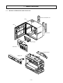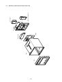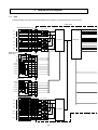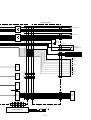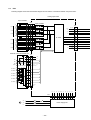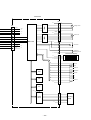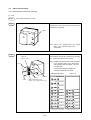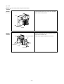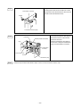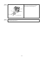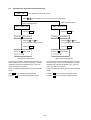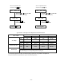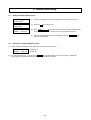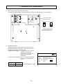
1
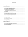
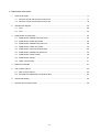
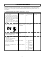
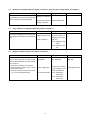
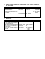
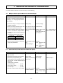
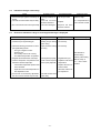
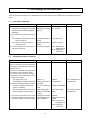
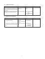
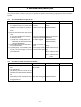
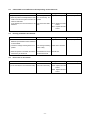
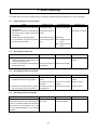
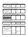
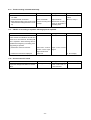
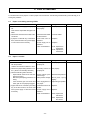
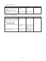
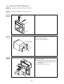
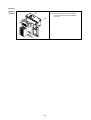
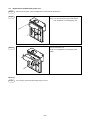
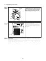
Instruction Manual
MICROJECT RECORDER
(PHA/PHC)
TROUBLESHOOTING
GUIDE
TN510410-E
CONTENTS
I. Troubleshooting Guide and Countermeasure
1.
The recorder is inoperative................................................................................................................
1
1.1
Nothing is displayed when the power supply switch is turned on. .............................................
2
1.2
Nothing is displayed when the power is turned on, and only the carriage motor is energized. ...
2
1.3
Only underline is displayed when the power is on.....................................................................
2
1.4
Display is abnormal when the power is on. ...............................................................................
2
1.5
Japanese characters are displayed in the English mode.
English characters are displayed in the Japanese mode. ..........................................................
3
Display is dim. .........................................................................................................................
3
Trouble about indication of measured value .....................................................................................
4
2.1
Multiple channels provide burnout or abnormal display.............................................................
4
2.2
Some channels provide burnout or abnormal display. ..............................................................
4
2.3
Indication changes excessively. ...............................................................................................
5
2.4
Erroneous indication is large or overrange/underrange is displayed. ........................................
5
Error display on the front panel .........................................................................................................
6
3.1
Chart End is displayed. ............................................................................................................
6
3.2
Carriage Abnormal is displayed. ...............................................................................................
6
3.3
Ink End is displayed. ................................................................................................................
7
3.4
Battery Alarm is displayed. .......................................................................................................
7
Abnormal test pattern print ................................................................................................................
8
4.1
The recorder does not print at all. .............................................................................................
8
4.2
One color or some colors are not printed. .................................................................................
8
4.3
Chart width is not sufficient to allow printing to the chart end. ...................................................
9
4.4
Printing characters are blurred. ................................................................................................
9
4.5
Print color is not correct............................................................................................................
9
1.6
2.
3.
4.
-i-
5.
Error on recording ............................................................................................................................. 10
5.1
Some channels are not recorded. ............................................................................................ 10
5.2
Recording is scaled out. ........................................................................................................... 10
5.3
Recording position is deviated. ................................................................................................. 10
5.4
Recording is printed step-like. .................................................................................................. 10
5.5
Recording is intermittent. Continuous recording is impossible. ................................................. 11
5.6
Trend recording is possible, but characters are not printed. ...................................................... 11
5.7
Recording color is changed midway through recording. ............................................................ 11
5.8
Recording and printing is duplicated. ........................................................................................ 11
5.9
Ink is blurring or smudging. ...................................................................................................... 11
5.10 Trend recording is dotted turbulently. ....................................................................................... 12
5.11 ON/OFF of recording is repeated. Message print is repeated. ................................................. 12
5.12 Unusual sound is heard. .......................................................................................................... 12
6.
7.
8.
Error on chart feed ............................................................................................................................ 13
6.1
Paper is not fed by pressing FEED. ......................................................................................... 13
6.2
Paper is not fed. ....................................................................................................................... 13
6.3
Paper will not thread. ............................................................................................................... 14
6.4
Paper is not properly folded. .................................................................................................... 14
Error on key action ............................................................................................................................ 15
7.1
Key operation is impossible. ..................................................................................................... 15
7.2
No setting can be made since your password slipped in mind. ................................................. 15
7.3
Closing the door turns recording ON/OFF or changes display. ................................................. 15
Other errors ...................................................................................................................................... 16
8.1
External control is impossible.
[Record ON/OFF, Selection of chart speed, Momentary value list printing] ................................ 16
8.2
Alarm signal is not outputted. ................................................................................................... 16
- ii -
II. Maintenance Information
1.
2.
3.
Name of each part ............................................................................................................................ 17
1.1
Structure of PHA and the name of each unit............................................................................. 17
1.2
Structure of PHC and the name of each unit ............................................................................ 18
Internal block diagram ....................................................................................................................... 20
2.1
PHA ......................................................................................................................................... 20
2.2
PHC ........................................................................................................................................ 22
Replacement of components ............................................................................................................ 24
3.1
Replacement of Model PHA main board .................................................................................. 24
3.2
Replacement of PHA relay board ............................................................................................. 26
3.3
Replacement of Model PHA power unit .................................................................................... 28
3.4
Replacement of PHC CPU board ............................................................................................. 30
3.5
Replacement of AI board of Model PHC ................................................................................... 33
3.6
Replacement of Model PHC power unit. ................................................................................... 35
3.7
Replacement of input module .................................................................................................. 36
3.8
Replacement of Rope .............................................................................................................. 37
3.9
Option unit mounting ................................................................................................................ 41
4.
Method of initial start ......................................................................................................................... 51
5.
Use of TEST channel ........................................................................................................................ 52
5.1
Shift to TEST channel .............................................................................................................. 52
5.2
Zero/span fine adjustment of measured value .......................................................................... 53
6.
Internal data setting .......................................................................................................................... 55
7.
Selection of PHC power switch ......................................................................................................... 56
- iii -
I. Troubleshooting Guide
and Countermeasure
1. The recorder is inoperative
The recorder does not start with the power turned ON. Since the display unit is unusual, no setting can be carried out.
If something unusual which may affect the recorder's functions occurs, the troubleshooting guide below will help you in
solving problems.
1.1
Nothing is displayed when the power supply switch is turned on.
Check
Check the input voltage to AC terminal.
PHA: 85 to 300V AC
Probable Causes
Power supply is not
properly connected.
PHC: 85 to 150 V AC or 150 to 300 V AC
The PHC power must conform to the specifi-
Suggested Remedy
Reference Page
Connect the power ac- II. 7. Selection of PHC
cording to the specifica- power switch.
tions.
cations, or the power supply may be damaged.
1) Check the power spec. against the specifi
cations on the nameplate.
2) Since the PHC uses a selection power
switch on the rear panel, check the switch
position.
Check the connected terminals of the power.
(PHA)
AC AC G
Terminals are not properly connected.
Connect properly.
(PHC)
AC
AC
G
Replace. (250V AC, 1A)
Check fuses for burnout (only PHA). (Since Burn out.
the PHC fuses are contained within the power
unit, they are impossible to check.)
Pull the main unit from the case and check the The power unit is faulty.
5V power supply on:
Replace.
PHA: Main board CN6 or CN7
PHC: AI board CN5
5V power supply is not outputted: the power Card is defective.
unit is faulty or card is damaged.
5V power supply is normally outputted: the Main unit is defective.
main unit is faulty.
PHA: Replace the main
board.
PHC: Replace the AI
board.
PHA: Replace the relay
board or display
unit.
PHC: Replace the CPU
board or display
unit.
-1-
1.2
Nothing is displayed when the power is turned on, and only the carriage motor is energized.
Check
Probable Causes
If the system can start recording by pressing
the RECORD key, the power may not be sup-
Fluorescent character
Suggested Remedy
Reference Page
Connect properly.
display is not wired yet.
plied to a fluorescent character display.
Fluorescent character
display is defective.
1.3
Replace display unit.
Only underline is displayed when the power is turned on.
Check
Probable Causes
Suggested Remedy
The power is supplied but the control signal is
not supplied to the fluorescent character dis-
Fluorescent display
cable is disconnected.
Check cable. If cable
Card is damaged.
play unit.
PHA: replace the main
play.
Reference Page
is disconnected, replace the whole dis-
board.
PHC: replace the CPU
unit.
1.4
Display is abnormal when the power is turned on.
Check
Probable Causes
Suggested Remedy
Reference Page
Control signal to the fluorescent display is ab-
The battery is not properly installed.
Reinstall the battery
and start again.
II. 4. The method of
normal. Such errors may occur due to faulty
CPU or RAM error data or even when the bat-
Replace the battery
(TK7C9980P1) and
See the Manual, Chap.
8.
initial start
tery is removed.
1) Check that the battery is fit in position.
2) Check the battery voltage. (2.5V or more)
3) Make an initial start.
4) If the above remedy cannot correct the error, a card is probably damaged.
Battery voltage drop.
The card is damaged.
make an initial start.
PHA: Replace the
main board.
PHC: Replace the
CPU board.
-2-
1.5
Japanese characters are displayed in the English mode. English characters are displayed in
the Japanese mode.
Check
Probable Causes
Suggested Remedy
Selection of English/Japanese is made by
internal parameter settings.
The internal parameter
Set properly and make
an initial start.
setting is wrong.
1) After the setting has been changed, make
an initial start.
2) If not corrected by the remedy, the card is
Reference Page
II. 6. Internal data
setting method
II. 4. The method of
initial start
The card is damaged.
probably defective.
PHA: Replace the
main board.
PHC: Replace the
CPU board.
1.6
Display is dim.
Check
Probable Causes
Suggested Remedy
In the case where key action is possible but
part of the display is dim, the fluorescent dis-
Fluorescent display
tube is defective.
Replace the display
play unit is defective.
Where key action is impossible, the card may
Card is damaged.
PHA: Replace the main
board.
1) Turn off the power once and turn it on again.
2) Check if the keys can be manipulated by
pressing the SELECT key.
be damaged.
unit.
PHC: Replace the CPU
board.
-3-
Reference Page
2. Trouble with the indication of a measured value
For trouble with the indication of measured values, see the following:
2.1
Multiple channels provide burnout or abnormal display.
Check
Probable Causes
Suggested Remedy
Reference Page
If the signal is not properly inputted, a thermocouple or a resistance bulb provides burnout display. Or a voltage signal provides abnormal display.
1) Check if the wiring to the input terminal is
properly connected.
Wrong wiring.
Connect properly.
2) Check if the input terminal and the main
connector are properly connected.
The input terminal unit
Install correctly.
is not correctly installed.
A/D conversion module
Replace A/D conver-
II. 3. Replacement of
sion module.
After replacement, ad-
A/D converter module
3) When the following related channels (such
as CH1 - CH4 and CH2 - CH5) are abnor-
is faulty.
mal, any of the A/D converter modules may
be faulty.
just the input.
(Internally parallel processed channel)
CH1 & CH4:
CH7 & CH10
CH2 & CH5:
CH3 & CH6:
CH8 & CH11
CH9 & CH12
4) A/D converter control circuit and power
supply may be defective.
Power supply is defective.
Card is damaged.
Replace.
PHA: replace the main
board.
PHC: replace the AI
board.
2.2
Some channels provide burnout or abnormal display.
Check
1) Check if wiring to the input terminal is properly connected.
2) Check the input signal for disconnection.
3) Check the input signal setting pins.
If it exceeds the max. allowable input volt-
Probable Causes
Suggested Remedy
Wrong wiring.
Wire properly.
Wrong wiring.
Setting of input setting
Wire properly.
Reference Page
Set properly.
Manual, Chap. 5.
Replace.
After replacement,
II. 3.7 Replacement of
A/D converter module
pin is wrong.
age, the A/D converter module may be
destroyed.
Thermocouple, resistance
thermometer bulb ................... ± 10V
50mV, 500mV range .............. ± 10V
5V, 50V range ........................ ± 100V
4) The A/D converter module may be faulty.
The A/D converter
module is defective.
make an input adjustment.
-4-
2.3
Indication changes excessively.
Check
Probable Causes
1) Check if the input signal is excessively deflected.
Input signal deflects violently.
Use an input filter.
Manual, chap.7
2) The A/D converter module may be faulty.
The A/D converter
module is defective.
Replace.
II. 3.7 Replacement of
3) The control circuit of the card may be faulty.
The card is damaged.
Replace the main
board or AI board.
2.4
Suggested Remedy
Reference Page
A/D converter module
Erroneous indication is large or overrange/underrange is displayed.
Check
1) Check the input signal.
2) Check the input signal setting pin.
3) Check the following parameters on the input signal setting screen:
Probable Causes
Suggested Remedy
Input signal is abnormal.
Setting of input setting
Input the correct signal.
Set correctly.
pin is wrong.
Input parameter setting
Set correctly.
Reference Page
is wrong.
・ The type of signal is correct.
・ Rooter is ON.
See Manual for:
・ The industry value is set correctly.
・ The differential operation is specified.
Rooter setting
Industry value setting
4) Regulate the measurement value input.
5) Check if cold junction compensation error
affects the thermocouple input.
・ Cold contact temperature equals to that
Not regulated properly.
Regulate the input.
Cold contact temperature is poorly adjusted.
Adjust the cold contact
temperature.
Replace the A/D converter module.
of the terminals.
・ Adjust the cold contact temperature in
fine adjustment mode.
6) If errors are not corrected by adjustment,
the A/D converter module may be faulty.
After that, make an input adjustment.
The A/D converter module is faulty.
-5-
Manual, Chap. 9.
II. 5. Use of TEST
channel
3. Error display on the front panel
When the recorder causes an error, it self-diagnoses the contents of the error, and displays an error message on the front
panel.
3.1
Chart End is displayed.
Check
Probable Causes
Suggested Remedy
Chart paper is short.
Set a new chart paper.
Chart paper is not properly set.
Set correctly.
ity.
PHA: Check the chart end detector photo
The sensor is malfunc-
Clean the sensor.
sensor for impurity.
PHC: Check the chart end detector
tioning.
Sensor fixture is bent or
Repair or replace.
sensor for bends.
3) If each of the above is found usual, the
broken.
The card is damaged.
PHA: Main board or
1) Check the remaining chart paper and the
setting state of chart paper. If the paper
runs short, chart end will be displayed in-
Reference Page
termittently.
2) Check the sensor system for abnormal-
card may be abnormal.
repeating board.
PHC: Replace the
CPU board.
3.2
Carriage Abnormal is displayed
Check
Probable Causes
Suggested Remedy
Reference Page
When the power is turned on or while the recorder is recording, an error is sensed that
the carriage unit is not returned to the Home
position (Left end).
Once errors are detected, the carriage is not
reset until the power is turned on again.
1) Turn off the power, and turn it on again.
2) When the recorder head does not completely move, check if:
・ the carriage cable is cut
・ the carriage motor cable is connected.
3) When the recorder head moves, check if:
・ the head is installed correctly (hits
against something).
・ the carriage cable is wound or loosen.
・ the home position sensor is impure.
4) If each of the above items is not found
faulty, the carriage motor may be faulty,
or the power supply or card may be faulty.
Rope is cut.
Signal cables are not
connected.
Replace.
Connect cables.
It is not installed correctly.
Install the head correctly.
Rope setting is faulty.
Sensor is contaminated
Wind rope correctly.
or dusty.
Carriage motor is faulty.
Power supply is faulty.
Card is damaged.
Clean.
Replace.
Replace the power supply unit.
PHA: main board or
repeating board
PHC: Replace the
CPU board.
-6-
II.3.8 Replacement of
carriage cable
II.3.8 Replacement of
carriage cable
3.3
Ink End is displayed.
Check
Probable Causes
Suggested Remedy
The recorder detects ink shortage by counting the number of dots of ink injection. To re-
Ink alarm Clear is not
Carry out Ink Alarm
carried out.
Clear.
The card unit is faulty.
PHA: Replace the main
Reference Page
See Manual
place an ink head, an Ink Alarm Clear action
is required.
If display does not disappear with the ink alarm
clear action, the card unit may be faulty.
board.
PHC: Replace the CPU
board.
3.4
Battery Alarm is displayed.
Check
Probable Causes
1) Check if the battery voltage is dropped, or
connection is not wrong.
Battery voltage is
dropped.
Suggested Remedy
Replace the battery .
Connect correctly.
Battery connection is
wrong.
2) If display does not disappear by battery
replacement, the card unit may be defec-
The card unit is defective.
tive.
PHA: Replace the
main board.
PHC: Replace the
CPU board.
-7-
Reference Page
See Manual, Chap. 8.
4. Abnormal test pattern print
f any problems about recording or printing occur, print the test pattern. Take remedy by judging from how the test pattern
is printed.
4.1
The recorder does not print at all.
Check
1) Check the ink injection sound.
If the injection sound is not heard, head
installation is not complete, or the connector pin at the rear of the head is probably
broken.
Probable Causes
Suggested Remedy
Head installation is incomplete.
Install the head correctly.
Head connector pin is
broken.
Replace the head.
The cap is not detached.
Detach the cap and in-
Ink leaks from the head.
A nozzle is clogged.
stall head
Replace the head.
Reference Page
2) Remove the head from the main unit and
check :
a) if the cap is left attached to the head.
b) if ink does not leak.
c) Extrude ink. If the test pattern is not
printed in full color, the head nozzle may
be clogged with particles.
3) Check that the head driven cable connector is not disconnected.
4) Try printing again. And if it is still not printing at all, the power supply or card unit
may be defective.
Replace the head
Cable connection is
poor.
Connect cable correctly.
Power supply is faulty.
The card unit is faulty.
Replace the power supply:
PHA: replace the main
board.
PHC: replace the CPU
board.
4.2
One color or some colors are not printed.
Check
Probable Causes
1) Check the connector pin at the rear of the
The head connector
head.
2) Try to extrude ink.
pin is broken.
Suggested Remedy
Replace the head.
Bring blotting cloth into contact with the
head end to check that all colors are printed
out.
Repeat this procedure several times until
The nozzle is clogged.
all colors are printed. If not, the nozzle may
be clogged with dust.
-8-
Replace the head.
Reference Page
4.3
Chart width is not sufficient to allow printing to the chart end.
Check
1) Adjust the head position.
2) When the position is well adjusted, the chart
width is too narrow to print to the end, so
make an initial start.
If not adjusted, the card unit seems to be
defective.
Probable Causes
The head position is
not sufficiently ad-
Suggested Remedy
Reference Page
Adjust the head position. Manual, Chap. 9.
justed.
The card unit is defective.
PHA: Replace the main
board.
PHC: Replace the CPU
board.
4.4
Printing characters are blurred.
Check
1) Check the head backlash.
Deflection per dotted line seems attributed
to the backlash.
2) Check the carriage traveling arbor for impurities.
3) When ink injection is unstable, remove the
head and try to extrude ink.
4.5
Probable Causes
Suggested Remedy
Backlash is deflected.
Adjust the backlash.
The carriage traveling
arbor is dirty.
Clean with a soft cloth.
Air bubbles are mixed
Extrude ink.
Reference Page
Manual, Chap. 9.
in the head nozzle.
Print color is not correct.
Check
Probable Causes
Suggested Remedy
1) Make an initial start.
2) If not corrected, the card unit seems faulty.
The card unit is faulty.
PHA: replace the main
board.
PHC: replace the CPU
board.
-9-
Reference Page
5. Error in recording
For trouble about trend record or digital printing, the following troubleshooting guide will help you in solving problems.
5.1
Some channels are not recorded.
Check
Probable Causes
1) Print the test pattern to check if all colors
are printed out.
The head is faulty.
2) Check that no channel is recorded beyond
the left and right margins (overrange/
Recording beyond the
range.
underrange).
3) Check if the input setting is skipped.
Input setting is wrong.
4) Try an initial start. If it is still not recorded,
the card unit may be faulty.
The card unit is defective.
Suggested Remedy
Reference Page
Check the test pattern.
See Chap. 5.2 " below.
Set properly.
PHA: Replace the main
board.
PHC: Replace the CPU
board.
5.2
Recording is scaled out.
Check
1) Check if the indication of the measured
value is overranged or underranged, and
check the value for burnout.
2) Check if the measured values displayed
are within the range.
5.3
Suggested Remedy
Input is unusual.
Reference Page
2. Abnormal measured
values
Recording range is not
properly set.
Set the range properly.
Probable Causes
Suggested Remedy
Recording position is deviated.
Check
1) Check if the displayed measured values
are aligned with the recording position.
2) Check if the recording format is properly
set. (Auto range, zoom, zone record)
5.4
Probable Causes
2.Abnormal measured
values
Error of measured
value.
Recording position is
deviated.
Recording format is
Reference Page
Correct the recording
position.
Manual, Chap. 9
Set the format properly.
Manual, Chap. 7
improperly set.
Recording is printed step-like.
Check
Probable Causes
Check the industrial value settings.
Industrial value resoluIf the industrial values are set to integers between tion is low.
1 and 10, recording is printed out in steps since
the resolution is in an increment of 10. In this
case, add decimal points like 1.0 to 10.0 to raise
resolution.
- 10 -
Suggested Remedy
Add decimal point to increase the resolution .
Reference Page
5.5
Recording is intermittent. Continuous recording is impossible.
Check
Probable Causes
Recording is continuous in the range of
Chart speed is high.
Suggested Remedy
Reference Page
Decrease the speed.
300mm/H with PHA, and 400mm/H with
PHC. If recording is beyond this range, it is
intermittent.
5.6
Trend recording is possible, but characters are not printed.
Check
The recording chart speed is too high to print
characters.
Probable Causes
Suggested Remedy
Chart speed is high.
Decrease the speed.
Reference Page
Continuous: 300mm/H with PHA,
400mm/H with PHC
Dot:
5.7
50mm/H
Recording color is changed midway through recording.
Check
Probable Causes
Orange, green and purple are formed by mixing, as follows:
Orange (CH1, CH6)
Green (CH2, CH7)
Ink is short.
Suggested Remedy
Reference Page
Replace the head.
Red - Blue
Yellow - Blue
Purple (CH3, CH8)
Blue - Red
If any of the colors above are missing, the recording color looks different.
5.8
Recording and printing is duplicated.
Check
It may be influenced by the head backlash.
Probable Causes
Influence of backlash.
Suggested Remedy
Adjust head backlash.
If the carriage arbor is
Reference Page
Manual, Chap. 9
dirty, clean it.
5.9
Ink is blurring or smudging.
Check
Probable Causes
Suggested Remedy
1) Check the type or quality of the recording
chart.
Chart is not properly
set.
Use the standard re-
Trend recording lines
Deviate the recording
range or separate the
cording chart.
If the quality of the recording chart is different, ink may dry late or may be smudging.
Type of standard recording chart
PHA: PEX00BL1-1000B
PHC: PEX00DL1-5000B
2) Check if the trend recording lines of some
channels overlap and are not printed.
3) Try to extrude ink.
overlap.
Air bubbles are contained in the head
nozzle.
- 11 -
recording zone.
Extrude ink.
Reference Page
5.10 Trend recording is dotted turbulently.
Check
1) Check if indication of measured values is
not drifted.
2) Check if backlash is matched.
3) When dotted recorder is used, check if multichannel trend recording lines does not over-
Probable Causes
Suggested Remedy
2. Abnormal measured
Indication is drifted.
Error on backlash.
Trend recording lines
overlap.
lap
Reference Page
Adjust backlash.
values
Manual, Chap. 9
Deviate the recording
range or separate the
recording zone.
5.11 ON/OFF of recording is repeated. Message print is repeated.
Check
Probable Causes
Suggested Remedy
Reference Page
If the external control RECORD START/
STOP contacts are unstable or the chart end
comes out or don't come out, recording ON/
OFF is repeated. When Message Print is
specified at the beginning of recording, Message printing is repeated.
1) Remove the external control unit.
2) Check if the Chart End is displayed.
RECORD START/
STOP contact input
Input correct contact
signal.
signal is abnormal.
Chart end.
3. Error display.
5.12 Unusual sound is heard.
Check
Probable Causes
Suggested Remedy
Inspect the carriage travel arbor for contami-
Traveling arbor is dirty.
Use a soft cloth to
nation.
clean the arbor.
- 12 -
Reference Page
6. Error in chart feed
For troubles about chart paper is not fed or paper does not advance the following troubleshooting chart will help you in
solving the problems.
6.1
Paper is not fed by pressing FEED.
Check
Probable Causes
Suggested Remedy
1) Check if the recording paper is properly
set.
Recording paper is not
set properly.
Set properly.
2) Check if the chart feed motor cable is disconnected.
Chart feed motor cable
is disconnected.
Connect cables.
3) If paper is not fed with any of the above
items, the chart feed motor, power supply
Chart feed motor is
defective.
Replace.
Power supply unit is
defective.
Replace.
Card unit is defective.
PHA: Replace the
main board.
Reference Page
Chart feed is impossible with paper set
afloat.
or card unit is found to be faulty.
PHC: Replace the
CPU board.
6.2
Paper is not fed.
Check
Probable Causes
1) Check if the chart perforation is aligned
Recording chart is not
with the sprockets.
Check if the chart end is broken or bent.
Suggested Remedy
Set properly.
properly set.
2) Check if the paper setting direction is correct. (Chart is set vertically with PHC)
Recording chart is not
properly set.
Set properly.
3) Check the following items with PHC.
・ Paper retainer at the rear of chart cas-
Paper retainer pres-
Decrease the pressure.
sette is too strong.
・ Main frame plate spring pressure is too
sure is large.
Plate pressure is large.
Bend plate spring
strong.
・ Chart cassette gear and chart feed
Gear engagement is
slightly.
Adjust the gear position.
motor gear are not properly engaged.
4) If paper feed is not corrected by checking
not proper.
Chart feed motor is de-
Replace.
any of the above items, the chart feed
motor, power supply or card unit is found
fective.
Power supply unit is
Replace.
to be faulty.
defective
Card unit is defective.
PHA: Replace the
main board.
PHC: Replace the
CPU board.
- 13 -
Reference Page
6.3
Paper will not thread.
Check
Probable Causes
Suggested Remedy
Chart paper is not
properly set.
Set correctly.
Paper contacts with the
head.
Set the head properly.
Check
Probable Causes
Suggested Remedy
1) Check the type or material of chart paper.
Some chart paper cannot be well folded
Chart paper is not properly set.
Use the standard chart
paper.
The chart paper is not
Set it properly by fold-
properly set.
ing a length of 2-3
sheets at each perfo-
1) Check if the chart paper is properly set:
Check if the chart paper end does not tear
or bend.
Check if the sprocket is not leaned.
2) Check if the head comes in contact with
chart paper.
6.4
Reference Page
Manual, Chap. 5.
Paper is not properly folded.
depending upon the material of chart paper.
Types of standard chart paper:
PHA: PEXOOBL1-1000B
PHC: PEXOODL1-5000B
2) Check if the chart paper is properly set.
3) Leaving the chart paper set for a long time
may make it difficult to fold.
It has been left unused
for a long time.
- 14 -
rated line.
Feed paper a little with
FEED and then proceed to recording.
Reference Page
7. Error in key action
7.1
Key operation is impossible.
Check
Probable Causes
Suggested Remedy
1) Confirm that key action is impossible dur-
Key is used during
printing.
Press the LIST key to
stop list printing.
Error is being caused.
Clear the Error state.
The card unit is defective.
PHA: Replace the main
ing printing.
It is impossible to use the key while a daily
Reference Page
report, an integrated list or a momentary
value list, etc. is printing.
2) Check if error messages are displayed.
If an error such as Chart End or Carriage
Abnormal is caused, the setting screen
does not appear.
3) Make an initial start.
If not corrected by the above remedies, the
unit card is found faulty.
board,
PHC: Replace the CPU
board.
7.2
No setting can be made since your password slipped in mind
Check
Probable Causes
Make an initial start.
Make an initial start.
7.3
Suggested Remedy
Reference Page
II. 4. Initial Start
Closing the door turns recording ON/OFF or changes display.
Check
The back door may come in contact with the
key switch.
Probable Causes
Door is faulty.
- 15 -
Suggested Remedy
Replace.
Reference Page
8. Other errors
8.1
External control is impossible. [Record ON/OFF, Selection of chart speed, Momentary value
list printing]
Check
Probable Causes
1) Check if the external control unit is prop-
The external control
erly installed.
Check if the connector pin is properly con-
unit is not properly installed.
nected.
2) Check if D11 or D12 is specified with mes-
Message print is speci-
Change the Message
sage printing.
3) Check if an alarm latch is specified.
fied.
Used for alarm latch
print.
Turn the alarm latch
OFF.
OFF.
8.2
Suggested Remedy
Reference Page
Install properly.
Alarm signal is not outputted.
Check
Probable Causes
Suggested Remedy
1) Check if the alarm output unit is properly
installed.
The unit is not properly
Install the unit properly.
installed.
Check that the connector pin is properly
connected.
2) Check if the alarm output contact capacity
is sufficient.
Relay contacts: 240VAC/3A,
30V DC/3A
If the output power exceeds the contact
capacity, it may cause damage to the sys-
The alarm output power
Install relays with a
exceeds the specified
contact capacity.
large contact capacity
external to the system.
The alarm unit is defec-
Replace the alarm unit.
tive.
tem.
- 16 -
Reference Page
II. Maintenance Information
1. Name of each part
1.1
Structure of PHA and the name of each unit
External control/alarm unit
Case
Door
Input terminal
Power supply
Main board
Repeating board
Display unit
– 17 –
Door
Case
AI board
Power supply
Rear panel
External control/alarm unit
Input terminal
1.2
Structure of PHC and the name of each unit
– 18 –
CPU board
PHC unit
Display unit
Chart cassette
– 19 –
2. Internal block diagram
2.1
PHA
Following diagram shows the internal block diagram of PHA and the connections between component units.
Main board
Input terminals (CH1∼6)
B6
CH1
CH2
CH3
CH4
CH5
CH6
i+
i–
i0
i+
i–
i0
RCJ1
CH1 input module
CH2 input module
A9
A10
B10
CH3 input module
A12
B12
B11
i+
i–
i0
i+
i–
i0
i+
i–
i0
CN4
A5
A6
B5
A7
RCJ2
CH4 input module
i/o cpu1
B8
B7
A8
CH5 input module
B4
B3
A4
CH6 input module
A1
B1
A2
i+
i–
i0
External control and
alarm unit
12 V
CN7
12 V
5V
A1,B1
A6,B6
12 V
5V
A9
Di1
Di2
Di3
COM
B8
A8
A2,B2
0V
12 V
ALARM1
B5
ALARM2
A5
ALARM3
B4
ALARM4
A4
ALARM5
B3
ALARM6
A3
0V
A7,B7
0V
Alarm unit
CN6
12 V
ALARM7
B5
ALARM8
A5
ALARM9
B4
ALARM10
A4
ALARM11
B3
ALARM12
A3
0V
A7,B7
Input terminals (CH7∼12) CN5
B6
CH7
CH8
CH9
i+
i–
i0
i+
i–
i0
RCJ1
A12
B12
B11
A7
CH10
CH11
CH12
i+
i–
i0
i+
i–
i0
i+
i–
i0
RCJ2
CH7 input module
A5
A6
B5
A9
A10
B10
i+
i–
i0
0V
CH8 input module
CH9 input module
CH10 input module
B8
B7
A8
B4
B3
A4
A1
B1
A2
CH11 input module
CH12 input module
– 20 –
i/o cpu2
Main cpu
Repeating board
A17,B17
12 V
A15
CN1
CN1
CN5
1,2
3
B15
4
A16
5
B16
6
CN8
A3,B3
12 V
A1
M
Carriage motor
M
Chart motor
1,2
3
B1
4
A2
5
B2
6
A19
A27
5V
A20
B29
HP
detecting
sensor
B19
0V
A25
Soldering
5V
Chart end
detecting sensor
0V
A23
B25
B23
CN4
A24
5V
B24
A6,B6
A7,B7
A22
A8,B8
0V
B22
B4
ENTRY
A4
RECORD
B3
▽
A3
DISPLAY
B2
ROM
△
A2
LIST
B1
A14,B14
5V
SELECT
5V
A1
FEED
A21,B21
A18,B18
A28,B28
0V
RAM
A5,B5
0V
0V
A7,B7
RTC
100 V
CN2
A32
Head
driver
B2
A31
A3
B30
B3
A30
A1
B32
B1
0V
5 V 0 V 12 V 0 V 100V 0V AC AC
CN8
3
4
5
6
1
2
7
8
AC
Power supply unit
A2
B31
AC
G
– 21 –
Recording
head
2.2
PHC
Following diagram shows the internal block diagram of PHC and the connections between component units.
Analog input board
Input terminals
CN2
1
CH1
CH2
CH3
i+
i–
i0
RCJ1
Input modules
4
CN3
3
2
6
CH4
CH5
CH6
A9, B9
0V
5
10
12 V
A8, B8
0V
A7, B7
5V
A3, A4, B3
0V
A1, B1
A2, B2
9
8
11
i+
i–
i0
i+
i–
i0
i+
i–
i0
A10, B10
100 V
7
i+
i–
i0
i+
i–
i0
RCJ2
i/o CPU
14
13
12
17
16
15
20
19
18
External control and alarm unit
CN1
12 V
12 V
5V
A1, B1
A6, B6
12 V
5V
A9
Di1
B8
Di2
A8
Di3
A2, B2
COM
0V
12 V
ALARM 1
B5
ALARM 2
A5
ALARM 3
B4
ALARM 4
A4
ALARM 5
B3
ALARM 6
A3
0V
A7, B7 0 V
5V
CN5
1
0V
2
0V
3
12 V 100 V 0 V
4
5
6
5V
7
0V
8
AC
Power supply unit
AC
G
– 22 –
AC
9
AC
10
CPU board
CN1
1, 2
12 V
3
CN6
4
A10, B10
A9, B9
M
Carriage motor
M
Chart motor
5
100 V
6
0V
A8, B8
12 V
A7, B7
0V
12 V
CN2
1, 2
3
4
5
6
Main CPU
A3, A4, B3
5V
A1, B1
A2, B2
0V
5V
HP sonsor
0V
Chart end
detecting sensor
0V
Fluorescent display
CN3
5V
B6
B5
0V
A6
A1
FEED
B1
LIST
A2
DISPLAY
B2
RECORD
ROM
A3
ENTER
B3
▽
A4
△
RAM
B4
SELECT
0V
A5
RTC
100 V
A2
B2
Head
driver
A3
B3
A1
0V
– 23 –
B1
Recording
head
3. Replacement
3.1
Replacement of Model PHA main board
Step 1
Turn off the power.
Step 2
Remove the right and left lock screws by turning
them counterclockwise.
Step 3
Grip the paper feed frame by hand and pull it firmly
toward you, and the main unit can be removed.
Step 4
Remove the external control/alarm units from the
rear panel of the main unit for easy re-assembly.
– 24 –
Step 5
Disconnect the cable from the power unit.
Step 6
Remove 8 lock screws and remove the main
board.
Mounting
Step 7
For mounting procedures, reverse the procedures in step 1 to step 7.
– 25 –
3.2
Replacement of PHA relay board
Step 1
Turn off the power.
Step 2
Remove the right and left lock screws by turning
them counterclockwise.
Step 3
Grip the paper feed frame and pull it firmly toward
you, and the main unit can be removed.
Step 4
Remove all connectors (4) from the relay board
and main unit.
Connector
– 26 –
Step 5
Step 6
Remove 2 screws and remove the relay board
from the main unit
Note) Use care when removing screws to avoid
dropping the screw nuts inside of the
machine.
Remove the remaining 4 cables by soldering. Now, The removing procedure has been completed.
Mounting
Step 7
Solder 4 cables according to the color and number given below:
A combination of color and number
➀-black, ➁-red, ➂-blue, √ -orange
Step 8
Mount the relay board on the main unit.
After checking that the detector unit of the photo
sensor is aligned with the recording head, install
two screws.
Photo sensor
Step 9
From the next procedures, reverse the order to step 4.
– 27 –
3.3
Replacement of Model PHA power unit
Step 1
Turn off the power and remove receptacles.
Step 2
Remove the right and left lock screws by turning
them counterclockwise.
Step 3
Grip the paper feed frame and pull it firmly toward
you.
This detaches it from the main unit.
Step 4
Disconnect the cables from the main board.
Step 5
Remove 4 screws from the corner of the main
board.
Since the GND is attached to the screws below the
left , use care about it when mounting the unit.
– 28 –
Step 6
Disconnect the cable from the power terminal, and
remove the power unit.
Now, the removing procedures are completed.
Mounting
Step 7
Mount by reversing the replacement order.
– 29 –
3.4
Replacement of PHC CPU board
Step 1
Turn off the power supply.
Step 2
Open the front panel and remove the main unit as shown below.
Step 3
Hold the paper feed unit drawing levers by fingers
and pull the paper feed unit toward you.
Step 4
Loosen the lockscrew (M4) inside the unit by using
a driver.
Step 5
Press down the rectangular hole of the bottom
base and pull it toward you, the main unit can be
removed.
– 30 –
Step 6
Remove Miller sheet
Miller sheet
Step 7
Remove two screws fixing the CPU board.
Step 8
Use care when mounting the flexible cables on
the display and the chart paper to prevent tear.
Remove the remaining 3 screws.
Flexible cable
Connector
– 31 –
Step 9
Remove gland plane and remove 3 cables by
soldering.
• Battery cable
• Chart end sensor cable
• Sensor cable for head position detection
Now, it completes removing step.
Mounting
Step 10
Reverse the preceding steps when mounting.
– 32 –
3.5
Replacement of AI board of Model PHC
Step 1
Turn off the power and disconnect a receptacle.
Step 2
Remove all terminals from the rear of the unit.
Step 3
Flat head screw
Remove flat head screws of the power switch.
Step 4
Remove 2 screws from the rear panel plate, and
remove the rear panel plate.
Note) Use care not to drop nuts.
Rear panel plate
Step 5
Remove the connectors from the power unit and
remove the AI board.
Note) When electrical units are mounted, remove
the support for electrical units and remove
the AI board.
Now, it completes removing steps.
– 33 –
Mounting
Step 6
For mounting, reverse the preceding steps.
Note) Keep in mind that spacers should be
mounted when the rear panel plate is
mounted.
– 34 –
3.6
Replacement of Model PHC power unit.
Step 1
Remove the AI board. (refer to Replacement of AI board for Model PHC)
Step 2
Remove 2 screws fixing to the rear panel plate.
Note) Use care when removing screws fixed to
both ends them to avoid dropping nuts.
Step 3
Remove the power unit.
Finally, it is completed by removing the power
cables
Mounting
Step 4
For mounting, reverse the preceding steps to mount.
– 35 –
3.7
Replacement of input module
Step 1
Gland plane
Step 2
Replacement of input module
Remove any defective input module by using a
solder absorbing device, replace it with new one
(by soldering).
Input module
Step 3
Removing card and gland plain:
For Model PHA, the input modules are mounted on
the main board, and the AI board for Model PHC.
Since the gland plain is connected to the card,
remove the card. The following shows an example
of the AI card as well as the AI card.
CH1 CH2 CH3 CH4 CH5 CH6
Input calibration
Perform calibration of the channel of which the input module was replaced. For input calibration, refer to
Instruction Manual, Chapter 5.
When CH1, CH4, CH7 or CH10 is replaced, it is indispensable to make a calibration of cold junction compensation. Refer to II. 5 Use of TEST channel.
– 36 –
3.8
Replacement of Rope
3.8.1 Replacement of PHA
Step 1
Remove the paper feed frame by turning lock
screws (on the right and left) counter-clockwise.
Step 2
Pull the paper feed frame forward to remove the
main unit.
Since a bearing from the tension fixtures hooks the
case, pull the main unit forward while pressing it
inside with a small tool like a driver.
Tension fixture and the bearing are described in ≈ .
Step 3
Remove the display unit
• Loosen two screws on both sides.
• Remove the connector in the rear.
↓
Remove the display unit.
– 37 –
Step 4
Attach the left-handed wire to the pulley through
the bearing.
Ball insertion hole
Wire
Wire
Pulley
Ball
Bearing
Pulley
Carrier
Step 5
Wind wire attached to the pulleys
Step 6
Attach the right-hand wire to the pulley side
through the bearing.
Bearing
– 38 –
Step 7
Hold down Part A , wind the wire on the
pulley, and insert the wire ball into the
pulley hole.
Tension spring
Tension fixture
Bearing
Part A
Ball
Step 8
Check wire for winding.
Left wire
Right wire
Move the carrier to the both sides.
Step 9
Reassemble by reversing steps ➀, ➁ and ➂.
– 39 –
3.8.2 Replacement of PHC rope
➀
Motor unit
(Longer wire)
(Red)
Wire
(Black)
(Shorter wire)
FPC
➁
Carrier unit
Wore
Cable insertion direction
– 40 –
3.9
Option unit mounting
3.9.1 Alarm/external control unit mounting
(1) PHA
Step 1
Turn off the power prior to work.
Step 2
Remove the two blind seals which are attached to
the right of the rear of the main unit, so that the two
connectors are exposed.
Seal
Note: Alarm 1 to 12, external control 1 to 3: 2 seals
Alarm 1 to 6, external control 1 to 3: 1
seal (lower)
Step 3
Insert two plugs from the alarm/external control
unit and alarm unit into the connectors on the main
unit. Fasten them with two lock screws.
Alarm unit
(Alarm 7 to 12)
Note: Install the alarm/external control unit (alarm
1 to 6, external control 1 to 3) to the lower
part and alarm unit plug (alarm 7 to 12) to
the upper part.
If they are not properly installed, the
external controls will not function.
Screw
Alarm/external control
21
CHART SPEED CHANGE
12
22
Alarm/external control unit
(Alarm 1 to 6, external control 1 to 3)
RECORD START
41
ALARM 7
42
ALARM 8
43
ALARM 9
44
ALARM 10
45
ALARM 11
46
24
25
26
27
36
19
ALARM 6
35
18
ALARM 5
34
17
ALARM 4
33
16
ALARM 3
32
15
ALARM 2
31
14
ALARM 1
28
13
– 41 –
23
DATA PRINT
29
Screw
Connector
11
Plug
Alarm unit
ALARM 12
(2) PHC
Step 1
Turn off the power and proceed as follows.
Step 2
Tear the blind seal from the main unit’s rear panel,
so the connector is exposed.
Seal
Step 3
Alarm/external unit
Connector
Plug
Screw
– 42 –
Insert the alarm/external control unit plug into the
connector on the main unit.
Fasten them together with three lock screws.
3.9.2 RS485 transmission card mounting
(1) RHA
Step 1
Turn off the power.
Step 2
Tear the seal from the rear upper left of the main
unit. The transmission terminal mounting hole is
blocked by this seal.
Seal
Step 3
Remove the two lock screws by turning them
counterclockwise.
Step 4
To remove the main unit, hold down the paper feed
frame with your hand and pull it forward.
– 43 –
Step 5
Bring the transmission connector close to the
mounting hole at the rear of the main unit. Place
the projection at the terminal top into the main unit,
and affix it with the attached screws.
Transmission connector
Screws
Transmission terminal (RD)
Step 6
Connector
Internal printed circuit board
Plug
Insert the transmission card plug into
the black connector of the internal
printed circuit board.
Affix the transmission card with two
lock screws. Relay the transmission
plug to the transmission connector.
Transmission
connector
Transmission card
Screws
Transmission plug
Step 7
Reverse the procedures described in steps 3 and 4 to return the main unit to the case.
– 44 –
(2) PHC
To add the RS-485 transmission function, observe the mounting procedures of the RS-485 transmission card
Step 1
Turn off the power.
Step 2
Open the front door to remove the main unit from the case as shown below.
Step 3
To withdraw the paper feed unit, hold the left and
right paper feed unit drawer levers with your
fingers and pull it forward.
Step 4
Loosen the main unit internal lock screws (M4) with
a screwdriver.
Step 5
Place a finger on the rectangle that is on the lower
base plate to pull it forward.
The main unit can now be separated from the
case.
– 45 –
Step 6
Insert the RS-485 transmission card plug into the
connector of the internal printed circuit board.
Affix them with two lock screws (M2 x 5).
Connector
Plug
Support
Screws
Transmission card
Step 7
• After work has been completed, return the main unit to the case and affix with lock screws.
• Reinstall the paper feed unit.
– 46 –
3.9.3 Fluorescent lamp unit mounting
(1) PHA
Step 1
Turn off the power.
Step 2
Remove the fluorescent lamp unit by turning the
right and left lock screws counterclockwise.
Step 3
To remove the main unit from the case, hold the
paper feed frame and pull it forward.
Step 4
Remove the right and left mounting screws from
the display unit. Remove the display unit from the
main unit.
– 47 –
Step 5
Remove the connector from the display unit and
main unit.
Step 6
Place the fluorescent lamp unit onto the rear of the
display unit and affix with two mounting screws.
Step 7
Relay the display unit to the main unit connectors
(2).
Step 8
Reassemble the main unit by reversing the procedures in steps 2, 3 and 4.
– 48 –
(2) PHC
Step 1
Turn off the power.
Step 2
To remove the paper feed unit, hold the right and
left paper feed unit drawer levers and proceed to
pull it forward.
Step 3
Loosen the main unit internal lock screws (M4) with
a driver.
Step 4
Place your finger on the rectangle on the lower
base plate and pull it forward.
The main unit can now be removed from the case.
Step 5
Affix the lighting device unit to the rear of the main
unit with two mounting screws.
– 49 –
Step 6
Connect the lighting device unit cable to the left
connector on the main unit upper printed circuit
board.
Keep the cable in the space provided between the
main unit and motor.
Step 7
Fix the lamp unit to the front panel of the main unit
with two screws.
Step 8
Insert the lamp cable connector into the lighting
unit.
Step 9
Reassemble the main unit by reversing the procedures in steps 2, 3 and 4.
– 50 –
4. Method of initial start
If an error occurs in the recorder’s internal memory when the battery is removed or when parts are faulty, the recorder
cannot be started even if the power is turned on again.
The following steps should be observed to make an initial start:
(1) Hold down the
keys simultaneously and turn on the power.
(2) The internal memory data is completely initialized by the procedures above.
• Clock resetting is required.
• Head zero-span adjustment or backlash adjustment is required.
• Set again since the input type or range setting values are initialized.
If the displayed characters are wrong, select the Japanese or English mode you, desire as described in II. 6.
– 51 –
5. Use of TEST channel
A TEST channel is provided for input calibration and testing at the factory.
5.1
Shift to TEST channel
ADJUST CH
ZERO SPAN
Allow the input calibration panel to be displayed according to the Manual.
SEL
TEST = OFF
The test channel is displayed.
The following display is selected by
ENT
TEST CH
or
keys.
TEST = ZERO TUNE
TEST = SPAN TUNE
Zero point of input calibration
Span point of input calibration
value can be moved. value
can be moved.
Zero point of input calibration
Span point of input calibration
value can be moved. value
can be moved.
OFF
Select Channel No.
ENT
TEST CH1 OFF
23.0°C
Select the channel number and press the ENT key.
The corresponding channel data will be displayed.
The displayed channels correspond as follows:
PHA: CHI to CH12: CH1 to CH12 of the measured values
CH13: Cold contact compensation temperature 1 (for CH1 to 3 compensation)
CH14: Cold contact compensation temperature 2 (for CH4 to 6 compensation)
CH15: Cold contact compensation temperature 3 (for CH7 to 9 compensation)
CH16: Cold contact compensation temperature 4 (for C10 to 12 compensation)
PHC: CH1 to CH6: CH1 to CH6 of the measured values
CH7: Cold contact compensation temperature 1 (for CH1 to 3 compensation)
CH8: Cold contact compensation temperature 2 (for CH4 to 6 compensation)
– 52 –
5.2
Zero/span fine adjustment of measured value
TEST = OFF
Fine adjustment of measured value.
Press
keys to display zero point or span point fine adjustment.
(Span point adjustment)
(Zero point adjustment)
TEST = ZERO TUNE
TEST = SPAN TUNE
Press the ENT key.
TEST Ch
ZERO TUNE
Press the
TEST Ch
Press the ENT key.
TEST Ch
or
key
SPAN TUNE
Press the
or
key
to set calibration object channel.
to set calibration object channel.
Press the ENT key.
Press the ENT key.
ZERO TUNE
TEST Ch
SPAN TUNE
<Span point fine adjustment>
<Zero point fine adjustment>
The current input value corresponding to the input type
and unit setting for each channel is displayed. Add the
specified span point fine adjustment input. (For input
value, see Table on next page.)
The current input value corresponding to the input type
and unit setting for each channel is displayed. Add the
specified span point fine adjustment input. (For input
value, see Table on next page.)
Adjust if the displayed values deviate from the specified
values.
Adjust if the displayed values deviate from the specified
values.
Press
Press the
key to increase the displayed value.
Press the
key to decrease the displayed value.
Press the
key to increase the displayed value.
key to decrease the displayed value.
– 53 –
Set to the specified value
Set to the specified value
and press the ENT key.
and press the ENT key.
TEST = ZERO TUNE
TEST = SPAN TUNE
Press the
or
key to turn OFF
Press the
the fine adjustment display.
or
key to turn OFF
the fine adjustment display.
TEST = OFF
TEST = OFF
Press the ENT key
Press the ENT key
to end fine adjustment.
to end fine adjustment.
TEST Ch
OFF
TEST Ch
OFF
Input values for zero/span fine adjustment of measured values
Zero fine adjustment
Type of input
DC voltage
Thermocouple bulb
Thermocouple
Span fine adjustment
Input value
Display value
Input value
Display value
50V
0V
0.00V
50V
50.00V
5V
0V
0.000V
5V
5.000V
500mV
0mV
0.0mV
500mV
500.0mV
50mV
0mV
0.00mV
50mV
50.00mV
Pt
100Ω
0.0°C
313.59Ω
600.0°C
JPt
100Ω
0.0°C
317.28Ω
600.0°C
K
0mV
0.0°C
54.807mV
1370.0°C
The input type is also available for types other than K. Select the span point input
value according to the corresponding thermocouple type.
The terminal temperature should be measured during cold junction compensation fine adjustment.
Zero point should be compensated for by the measured temperature.
– 54 –
6. Internal data setting
6.1
Shift to absolute address mode
ADJUST CH■
ZERO SPAN
(1) Allow input calibration panel to be displayed according to Manual, Chap. 9.
ADJUST CH0
ZERO SPAN
(2) Press the
RAM READ/WRITE
ADDR. 0 DATA. 80
(3) Press FEED ,
at the same time to select the absolute address mode,
so the write/read process is carried out in or from the internal memory.
key to set to CH 0.
(4) After the absolute address action is completed, press the DISPLAY key to
return to the initial state.
6.2
Selection of Japanese/English mode
(1) Select the absolute address mode and set the contents of the address to 8.
RAM READ/WRITE
ADDR. 8 DATA. 69
Japanese: 78
English: 69
(2) Turn off the power once. Hold down the
,
keys simultaneously and turn on the power. (initial start)
Since making an initial start initializes all parameters, resetting is required.
– 55 –
7. Selection of PHC power switch
(1) Power supply voltage changeover switch setting
The switch is located beneath the nameplate (shown in part A) of the PHC rear panel. It is set as below:
AC
85 to 150VAC
50/60Hz
Power supply voltage
changeover switch
AC
G
Name plate (A)
AC85 to 150V
AC150 to 300V
(Upper)
(Lower)
Name plate (B)
Be sure to change the switch
over with the power OFF.
(2) Nameplate attachment
After the power supply voltage has been changed, be sure to
change the voltage in the nameplate. (Power in excess of the
specified value will destroy the instrument.)
➀ Specification nameplate .... Nameplates as shown below are
attached to the upper and
internal parts of the main case.
Rewrite the power supply
specification.
➁ Power supply nameplate ... Attach the following nameplates
to Part (A) and Part (B) shown
above.
AC85 to 1500
TK7E2256P1
AC150 to 3000
TK7E2256P2
}
A and B nameplates - 1 set
– 56 –
Type
Source
Ser. No.
Mid.
PHCG2221-NAOYY
85 to 132V AC 50/60Hz
NID1234T
O/A
9102
Fuji Electric Systems Co. Ltd.
Japan
Head Office
Gate City Ohsaki, East Tower, 11-2, Osaki 1-chome,
Shinagawa-ku, Tokyo 141-0032, Japan
http://www.fesys.co.jp/eng
Instrumentation Div.
International Sales Dept.
No.1, Fuji-machi, Hino-city, Tokyo 191-8502, Japan
Phone: 81-42-585-6201, 6202 Fax: 81-42-585-6187
http://www.fic-net.jp/eng