1
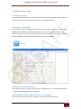
Configuration software OEM user manual SA F E Gosafe 797 GO Configuration Software OEM User manual 1 Configuration software OEM user manual Content 1. General Note ......................................................................................................................... 7 1.1 The aim of this document............................................................................................ 7 1.2Copyright ...................................................................................................................... 7 1.3Reference materials ..................................................................................................... 7 E 2. Software Overview ................................................................................................................ 8 2.1Software usage ............................................................................................................. 8 2.2Software operation ...................................................................................................... 8 SA F 2.3Structure of the software ............................................................................................. 8 2.4installation of the USB driver for the software ............................................................ 8 3. The usage of software ......................................................................................................... 11 3.1software starting ........................................................................................................ 11 3.2Device connection ...................................................................................................... 11 3.3Reading and writing the parameter ........................................................................... 12 3.3.1 Device Configuration page ............................................................................. 13 GO 3.3.1.1 OEM Password & Confirm Password................................................... 13 3.3.1.2 Time Zone Country & Time Zone......................................................... 14 3.3.1.3 PIN ....................................................................................................... 14 3.3.1.4 SMSC .................................................................................................... 14 3.3.1.5 APN ...................................................................................................... 14 3.3.1.6 Upload Data ......................................................................................... 15 3.3.1.7 Movement Sensor ............................................................................... 15 3.3.1.8 Movement Sensor Parameter ............................................................. 15 3.3.1.9Com Port Baud Rate & Mode ............................................................... 16 3.3.1.10Output GPS data from USB................................................................. 16 2 Configuration software OEM user manual 3.3.1.11 Immobilize ......................................................................................... 16 3.3.1.12 Mileage .............................................................................................. 16 3.3.1.13 Set Mileage ........................................................................................ 17 3.3.1.14 Extend Flash Set................................................................................. 17 3.3.1.15 interval............................................................................................... 17 E 3.3.1.16 reset parameter and system ............................................................. 17 3.3.2SMS Server page .............................................................................................. 18 3.3.2.1 SMS server NO. .................................................................................... 18 SA F 3.3.2.2SMS upload mode0 .............................................................................. 18 By this you decide disable or enable the SMS upload mode0. ....................... 18 3.3.2.3mode0................................................................................................... 18 3.3.2.4SMS upload mode1 .............................................................................. 19 By this, disable or enable the SMS upload mode0. ......................................... 19 3.3.2.5mode1................................................................................................... 19 3.3.2.3mode0................................................................................................... 19 GO 3.3.2.3mode0................................................................................................... 19 3.3.3 TCP/UDP page ................................................................................................ 20 3.3.3.1Heart Beat Interval ............................................................................... 20 3.3.3.2TCP Server ............................................................................................ 21 3.3.3.3Domain and TCP port and UDP port..................................................... 21 3.3.3.4TCP upload mode0 ............................................................................... 21 3.3.3.5 .............................................................................................................. 21 3.3.3.6TCP upload mode1 ............................................................................... 21 3.3.3.8TCP upload Buffer ................................................................................. 22 3.3.3.9 .............................................................................................................. 22 3 Configuration software OEM user manual 3.3.3.10TCP upload by distance ...................................................................... 22 3.3.3.11 UDP upload mode.............................................................................. 22 3.3.4 Phone page ..................................................................................................... 23 3.3.4.1SMS forwarding .................................................................................... 23 3.3.4.2 Voice Monitor NO................................................................................ 24 E 3.3.4.3 Hotline NO. .......................................................................................... 24 3.3.5User page......................................................................................................... 25 3.3.5.1 User phone NO. ................................................................................... 25 SA F 3.3.5.2User Password &confirm password ................................................... 25 3.3.5.3User upload Mode0 .............................................................................. 26 3.3.5.4 .............................................................................................................. 26 3.3.5.5User upload Mode1 .............................................................................. 26 3.3.5.7Hyperlink with GPS data ....................................................................... 26 3.3.5.8Hyperlink with base station data.......................................................... 27 3.3.5.9User command mask ............................................................................ 27 GO 3.3.6Alarm page ...................................................................................................... 28 3.3.6.1Alert mask............................................................................................. 28 3.3.6.6Alarm time ............................................................................................ 29 3.3.6.7interval.................................................................................................. 29 3.3.6.8over speed mask................................................................................... 30 3.3.6.9 over speed parameter ......................................................................... 30 3.3.6.10 Anti-jamming mask............................................................................ 30 3.3.6.11Imobilizer when anti-jamming ........................................................... 30 3.3.6.12paramete anti-jamming...................................................................... 30 3.3.6.12.1 Jamming channel and threshold ............................................ 30 4 Configuration software OEM user manual 3.3.6.13angle change alert mask ..................................................................... 31 3.3.6.13.1angle change time and degree ................................................ 31 3.3.6.14speed change alert ............................................................................. 31 3.3.6.14.1Speed change alert time and degree ...................................... 31 3.3.7Shortcut page .................................................................................................. 32 E 3.3.8 Dynamic page ................................................................................................. 32 3.3.9Geo-fence page ............................................................................................... 33 3.3.9.1enable/disable Gen-fence .................................................................... 33 SA F 3.3.9.2User geo-fence mask ............................................................................ 33 3.3.10G797 page...................................................................................................... 34 3.3.10.1 ............................................................................................................ 35 3.3.10.2 ............................................................................................................ 35 3.3.10.3 ............................................................................................................ 36 3.4Import and export the parameter .............................................................................. 37 3.5 note of Apnlist.txt file ................................................................................................ 37 GO 3.6note of Config.xml file ................................................................................................ 37 Document History 5 Configuration software OEM user manual GOSAFE product protocol Version number V2.1 Made by Imran Khan Audit Stella Issuing date 2011-07-15 GO SA F E Name of document 6 Configuration software OEM user manual 1. General Note 1.1 The aim of this document Gosafe provide this document to describe the functions and operation environment of configuration software, with the aim of providing a better understanding of using scope and approaches of the configuration software for the OEM manufacture, What’s more, this document also provides necessary maintaining and updating information for G797 1.2Copyright E configuration software. This document is a confidential document, Gosafe reserves all rights to this document and the information contained herein. Any individual or organization is strictly prohibited to reproduction, use or disclosure to the third party without permission. Otherwise, we hold SA F the right to investigate the legal responsibility. Company address: B301-306, 69 Guangpu West Road, Science & Technology Park, Guangzhou, China. Tel: +86-20-66679696 E-mail: info@gosafesystem.com Website: www.gosafesystem.com 1.3Reference materials GO G797 protocol and G797 user manual 7 Configuration software OEM user manual 2. Software Overview 2.1Software usage The Intended audiences of this document arethe distributor and reseller of G797. Who use the G797 device, this document also provides a fast configuration tool. 2.2Software operation E This software can be operatedon both the PC and the compatible machine, it can be used with Microsoft windows (compatible windows 7), at first, you should decompress the software, and then click the Iconsdirectly, then you can see the main menu of the software, GO SA F you can configure the device as you need. The specific is as following: 2.3Structure of the software The software consists of three parts, which are configuration file —config.xml; APN list file —apnlist.txt and executable file —G797.exe. 2.4installation of the USB driver for the software Please connect our device to your computer, you will see the below picture: 8 SA F E Configuration software OEM user manual GO Then choose the options as the below picture show you Then click the ‘next’ button to go to the below picture, and we choose as the below picture show you. Please note that when you are choosing the ‘Browse’ button, you should choose the configuration file folder. You should choose the configuration file folder which has the 9 Configuration software OEM user manual SA F E “Anytracking USB.inf” document. GO Then press ‘next’ button, you will see the below picture. Finally the installation is finish and we get the below picture. 10 SA F E Configuration software OEM user manual Note: If you have not do the installation of the USB driver, the device will cannot be connected to your computer. 3. The usage of software GO 3.1software starting Clicking the executable file G797.exe directly, entering into the main screen of the configuration software. 3.2Device connection The software will check the USB port automatically after started, if the device disconnect, it will remained you to connect the device with PC; If the device connect, the device will detect main information of device. This device can be drawn out in the course of usage, and it can connect with PC again. When it connected successful, the software will display the basic information of the device as following: 11 SA F E Configuration software OEM user manual If connection fails, you can set the serial port and Baud rate by hand (default baud rate is 9600), after finished, please click “Connect” button, then it can connect successfully. Look at GO the following picture: 3.3Reading and writing the parameter The software contains nine setting pages, there are both reading and writing button on each page. Each parameter has itself “check “button, after being selected, filling the correct parameter, click the “write” button, and then you can write the parameter into the device. 12 Configuration software OEM user manual GO SA F E 3.3.1 Device Configuration page The device configuration page contains the main setting for the device. The details of the setting are as follows: 3.3.1.1 OEM Password & Confirm Password The device contain OEM password and the default password is 0123456789. This password can be changed by selecting this parameter. It is recommended that don’t change the OEM password. 13 Configuration software OEM user manual 3.3.1.2 Time Zone Country & Time Zone The device can be set for the time zone. This time zone setting is only for the user. When user receives the SMS it will contain time and this time will be same as what time zone set in this parameter. 3.3.1.3 PIN The PIN is for the SIM card if the SIM card doesn’t have any PIN then no need to set this pin SA F 3.3.1.4 SMSC E code here. If the SIM card contain PIN code then it must be set here. SMSC is a message center number of the SIM card inside the device. Normally device take the SMSC number automatically from the SIM card but if device is not reply back to SMS this means that device is not able to read the SMSC number from the SIM card. In this case please set the SMSC number. The format of the SMSC is +Country Code SMSC number. Example: China mobile SMSC number is 13800200500. So the SMSC number must be set like +8613800200500 GO 3.3.1.5 APN The G797 are designed in such a way that it can read its memory to configure the APN automatically. Device need all the information need to store in its memory regarding the APN. The APN parameter is to set the APN List in the memory of the device. Reseller and Distributer can set all the APN list of their country in the file and configure it to the device. The APN list can be edit by pressing the Edit APN button. It will open a text file which contain all the APN list if set country APN is not available it can be added as follows: [ yyyy ] MCC=xxx; MNC=xx; APN=xxxxxxxx; USER NAME=xxxxxx; PW=xxxxxxx; MCC=xxx; MNC=xx; APN=xxxxxxxx; USER NAME=xxxxxx; PW=xxxxxxx; 14 Configuration software OEM user manual yyyy is country name MCC & MNC can get from the GSM service provider or can find from this link http://en.wikipedia.org/wiki/Mobile_Network_Code# Note that every GSM service provider has its own MCC and MNC. If the MCC and MNC is not correct the device will not set the APN. APN: access point name E USER NAME: this is the user name of the APN if there is no user name can leave this blank PW: This is the password for the APN. If there is no password for the APN can leave this blank In the above example there are two GSM operator added. If there are more operators then SA F just add more lines with their APN details. 3.3.1.6 Upload Data It can select what data device will upload to the server. There are four options 1. Device status 2. Mileage 3. AD (temperature & Power status) 4. Geo-Fence 5. OBDII GO 6. Fuel consumption 3.3.1.7 Movement Sensor The system can enable disable the movement sensor. Note: The upload modes are depended on movement sensor. If the movement sensor is disabled the user will not receive “Move Alarm” and also the system will keep one upload mode. 3.3.1.8 Movement Sensor Parameter The movement sensor parameters are to set the sensitivity of the movement sensor. Here we have three parameters 15 Configuration software OEM user manual 1. Stop to Move: Moving Last Time: This is time in seconds mean if the device moves for set time. Value range (1 ~ 255) 2. Move Thrash hold: This number of movement in the set time. Value range (1~255) 3. Move to Stop: This is time means if the vehicle stops for more than set time here will again send the move alarm to the user. If it stops less than set time here then it will 3.3.1.9Com Port Baud Rate & Mode E not send the move alarm to user. Value range (1~255) The device communication port baud rate can be set here. Click on the drop down menu to SA F select the baud rate. Default is 9600 The output mode can also be selected here. Click on the drop down menu and here we have three options 1. Normal:_______________ 2. GPS: 3. Debug: GO 3.3.1.10Output GPS data from USB Turn ON or OFF the GPS data output via USB. 3.3.1.11 Immobilize Enable disable the immobilizer feature. 3.3.1.12 Mileage Enable disable mileage calculation feature. 16 Configuration software OEM user manual 3.3.1.13 Set Mileage The system can store the mileage of the vehicle which is 0 when the tracker is just installed and can add the future GPS mileage automatically in it. And you can also set the initial mileage on the tracker. Please note that the number we have to enter here is in meters. The default value is 0. 3.3.1.14 Extend Flash Set E The system has internal memory which can record < 7000 records which can be sent to the SA F server on different mode. The extend flash memory is for storing overflow records. Parameter 1 0: over flow: when the RAM overflows, flash memory will store overflowed data. 1: All: the flash will store all the vehicle data (which is the default). Parameter 2 -----Flash data upload channel T: TCP channel (which is the default). D: UDP channel Parameter 3-----Flash upload option GO 0: Auto: upload automatically when GPRS signal exist (which is the default). 1: Request: upload by this command”EFR”. 2: Timer: upload by interval 3.3.1.15 interval When the flash upload option is 2: Timer. Then you need to set the interval time, the range can be 30~900S, 15~59M, 1~240H. Note: the default is 30M. 3.3.1.16 reset parameter and system Reset parameters means all the parameters will change to the factory default. Reset system means restart the device. 17 Configuration software OEM user manual E 3.3.2SMS Server page You can set the SMS server NO. and SMS server upload mode on this page. SA F 3.3.2.1 SMS server NO. You can get this NO. From your SIM card provider. This must be right, or you cannot get any messages from the device. 3.3.2.2SMS upload mode0 By this you decide disable or enable the SMS upload mode0. GO 3.3.2.3mode0 Parameter 1 G: GPS data: the message will tell you the location by showing you the longitude and latitude. S: Base station data: the message will tell you the location by showing you the base station data. L: Voice monitor: the device will can the voice monitor number by interval. Parameter 2 T: Text: the location datas’ format is text. Parameter 3 It is the interval of uploading the SMS. The value can be 30~900S, 15~59M, 1~240H. 18 Configuration software OEM user manual 3.3.2.4SMS upload mode1 3.3.2.5mode1 3.3.2.3mode0 SA F Parameter 1 E By this, disable or enable the SMS upload mode0. G: GPS data: the message will tell you the location by showing you the longitude and latitude. S: Base station data: the message will tell you the location by showing you the base station data. L: Voice monitor: the device will can the voice monitor number by interval. Parameter 2 T: Text: the location data’s’ format is text. Parameter 3 GO It is the interval of uploading the SMS. The value is 30~900S, 15~59M, 1~240H. 3.3.2.3mode0 Parameter 1 G: GPS data: the message will tell you the location by showing you the longitude and latitude. S: Base station data: the message will tell you the location by showing you the base station data. L: Voice monitor: the device will can the voice monitor number by interval. Parameter 2 T: Text: the location data’s’ format is text. Parameter 3 19 Configuration software OEM user manual It is the interval of uploading the SMS. The value can be 30~900S, 15~59M, 1~240H. GO SA F E 3.3.3 TCP/UDP page This page is used to set the parameter of TCP and UDP; please refer to protocol of G797. 3.3.3.1Heart Beat Interval This is for setting the heart beat data uploading interval. Note that the number is seconds. 20 Configuration software OEM user manual 3.3.3.2TCP Server Set the TCP Server address. The TCP port and UDP port are both necessary to set. 3.3.3.3Domain and TCP port and UDP port Set the Domain name if you do not know the server’s IP. The TCP port and UDP port are both 3.3.3.4TCP upload mode0 SA F Disable and enable the TCP upload mode0. E necessary to set. 3.3.3.5 Parameter 1 G: GPS data: the GPS data will be uploaded by the TCP channel. S: Base station data: the Base station data will be uploaded by the TCP channel. Parameter 2 T: Text: the data’s format will be text. GO B: Binary: the data’s format will be binary. Parameter 3 Data save interval can be set. The value is 30~900S, 15~59M, 1~240H. 3.3.3.6TCP upload mode1 See also TCP upload mode0. 21 Configuration software OEM user manual 3.3.3.8TCP upload Buffer You can set the quantity of records in every packet. When the records reach what you set, the device will upload the data automatically by the TCP channel. Note you have to enable the TCP Upload Buffer firstly. 3.3.3.9 by the TCP channel. SA F 3.3.3.10TCP upload by distance E The device will keep uploading automatically once it reach on certain percent of 1kb, like 30% The device will keep uploading automatically once it reach on certain distance by the TCP channel. 3.3.3.11 UDP upload mode Same explanation like the TCP upload mode. The only difference is that the upload channel GO changes to UDP channel. 22 Configuration software OEM user manual GO SA F E 3.3.4 Phone page This page is used to set phone list, including SMS forwarding list; monitor list and hotline list. 3.3.4.1SMS forwarding Our device can transfer the SMS from certain No. to certain No. it is usually used to set transferring the SMS from the telecommunication company to the user, for example, the payment reminder SMS. 23 Configuration software OEM user manual 3.3.4.2 Voice Monitor NO. Only the voice monitor No. can get the call from the device that can call automatically when it gets voice monitor command. And only when these numbers call the device, the device can automatically pick up the call to let you monitor. Once you set any No. of the list SA F E “”, then any phone No. can monitor the device. 3.3.4.3 Hotline NO. The Hotline No. can achieve two way communications with the device. Once you set any No. of the list “”, then any phone No. can achieve two way communication GO with the device. 24 Configuration software OEM user manual GO SA F E 3.3.5User page This page is used for setting user information, including user phone number; user password and user upload mode. 3.3.5.1 User phone NO. Set the user phone No. If you want to send some command to the device by the user phone, you have to set the same user phone No. 3.3.5.2User Password &confirm password Set the user password and confirm it. When the user needs to send the command to the device, the password is the essential part of the command. For details, see the command list. 25 Configuration software OEM user manual 3.3.5.3User upload Mode0 Enable and disable user upload mode0. 3.3.5.4 E Parameter 1 G: GPS data: the GPS data will be uploaded to the user phone No. S: Base station data: the Base station data will be uploaded to the user phone No. SA F L: Voice Monitor: it will can the user by interval to the user monitor. Parameter 2 T: Text: the location’s format will be text. W: Hyperlink: the location’s format will be hyperlink. Parameter 3 GO Data upload interval and voice monitor interval can be set. The value is 30~900S, 15~59M, 1~240H. 3.3.5.5User upload Mode1 Same explain as the user upload0. This another user upload mode to choose. 3.3.5.7Hyperlink with GPS data This is the setting for the hyperlink which user receives if he set the W mode. The default setting is Google map link but this can be changed to specific map link like Bing, Yandex or open street map. And you have to give the setting parameters. And this one is for the GPS data. 26 Configuration software OEM user manual 3.3.5.8Hyperlink with base station data This is the setting for the hyperlink which user receives if he set the W mode. The default setting is nothing but this can be changed to specific format. And you have to give the setting parameters. And this one is for the LBS data. For details, see the protocol. Generally 3.3.5.9User command mask E speaking, do not set this one. GO SA F This is used to allow which command the user can use. 27 Configuration software OEM user manual GO SA F E 3.3.6Alarm page This page is used to set alert mask, over speed parameter and anti-jamming parameter. 3.3.6.1Alert mask Here we have five alarms to choose. And there are four destinations to send these alarms, the user, the SMS server, the TCP server, the UDP server. See the below picture. 28 Configuration software OEM user manual 1. With the below picture, that means power alarm will be sent to the user. 2. With below picture, that means the power alarm will be sent to the SMS server only. It E will not be sent to the user, the TCP server, the UDP server. 3. With below picture, that means the power alarm will be sent to the SMS server and the TCP server. The move alarm will be sent to the user and the SMS server. The over-speed alarm will be sent to the SMS server only. The anti-jamming alarm will be sent to all the SA F four destinations. The Geo-fence alarm will be sent to the TCP server and the UDP server. GO 3.3.6.6Alarm time You can set the alarm times. This is for all the alarm. But to different destination, it can be different. You can set to the user two times. And at the same time, it can be 4 times to the SMS server, 0 times to the TCP server and 0 times to the UDP server. 3.3.6.7interval If we set the alarm 2 or more than 2 times, there must have the interval. So you can set the interval here. They are paired like the below picture shows. 29 Configuration software OEM user manual 3.3.6.8over speed mask Enable and disable the over speed alarm/alert. 3.3.6.9 over speed parameter Set the speed. If we set like the below pictures, the over speed alarm/alert is enabled. Once the vehicle speed is 80 or more than 80KM/H, the device will send the over speed alert. If SA F E the vehicle speed is 120 or more than 120KM/H, the device will send the over speed alarm. 3.3.6.10 Anti-jamming mask Enable and disable anti-jamming mask. 3.3.6.11Imobilizer when anti-jamming Enable and disable immobilizing the car when anti-jamming. 3.3.6.12paramete anti-jamming GO Like all in the soft ware, if you want to set any of them, you have to countermark like the below picture. If you leave it like the below picture, then it does not work no matter what you do with the parameters. Even you make it like the picture 2; the anti-jamming is still off. Picture 1 Picture 2 3.3.6.12.1 Jamming channel and threshold This is for setting on what kind of phenomenon will be considered as anti-jamming. 30 Configuration software OEM user manual 3.3.6.13angle change alert mask Enable and disable the angle change alert 3.3.6.13.1angle change time and degree E This is for setting on what kind of phenomenon to send the angle change alert. For example, if you set it like the below picture, then if the vehicle changes the angle more than 90 degree SA F in two seconds or less than 2 seconds, the device will send the angle change alert. 3.3.6.14speed change alert Enable and disable the angle change alert. 3.3.6.14.1Speed change alert time and degree This is for setting on what kind of phenomenon to send the speed change alert. For example, if you set it like the below picture, then if the vehicle changes the speed more than 100 GO degree in 4 seconds, the device will send the speed change alert. 31 Configuration software OEM user manual SA F E 3.3.7Shortcut page You can set shortcut for the commands on this page, there are 10 shortcuts,each one corresponds with different command. The specific corresponding parameter command can also be saved in the cmd list of config.xml file in advance. GO 3.3.8 Dynamic page You can set Dynamic upload mode 0 or mode1 for each status. There are six statuses to choose. If you set the front pages, that are the SMS Server page, the TCP and UDP page and user page, with different mode. Then on the corresponding status, if you choose mode0, all the front three pages set will work at mode0. Note: the condition is the three front pages mode have been set and enabled. 32 Configuration software OEM user manual SA F E 3.3.9Geo-fence page On the Geo-fence page, you can set enable/disable geo-fence and user mask of geo-fence. 3.3.9.1enable/disable Gen-fence We have total 28 Geo-fences can store in the device memory. Then you can choose some of them or all to let them work. If you choose it like the below picture, then only number 8, GO 9,17,18,26 and 27 will work. The others won’t work. 3.3.9.2User geo-fence mask This means you can choose on which geo-fence the user can get the alarm if there is any alarm. 33 Configuration software OEM user manual GO SA F E 3.3.10G797 page 34 Configuration software OEM user manual 3.3.10.1 Max Acceleration at Emergency and Max Acceleration at Accident is used for setting 3D G-force sensor. E Max Acceleration at Emergency: Parameter 1:acceleration speed threshold,unit 0.1g, Range :0-80, that is 0-8g. 0 means disable emergency acceleration detect feature Parameter 2: the duration of reaching acceleration threshold;unit:0.1S;range 2-20,that SA F is from 0.2Sto 2S Max Acceleration at Accident: Parameter: acceleration speed threshold,unit:0.1g, range :0-80; that is 0-8g. 0 means disable accident acceleration detect feature 3.3.10.2 GO Query Extend Flash Model: Check Flash model, just for query, cannot be set. Query Fuel Consumption: Check fuel consumption, just for query, cannot be set. 35 Configuration software OEM user manual SA F E 3.3.10.3 This one is for setting OBDII data uploading. It will decide which OBDII data can be uploaded. When you check your vehicle’s protocol, and you know which one is open by the vehicle manufacturer, you can just choose one of the 15 OBP data which have not been used for any OBDII data uploading, and then input the OBDII code you decide to upload. Click it like the GO below picture, then press the “write” button. In the future, you will get this OBDII data. 36 Configuration software OEM user manual 3.4Import and export the parameter Clicking the “import” button which is on the left side of the configuration software, Selecting the last exported configuration file, this can import the parameter to the software, and then click WriteAll button , you can write all the parameter into the device, after you finish, click the Export button, select the aim file to save your parameter into the file. 3.5 note of Apnlist.txt file Apnlist.txttion is made up of a lot of sections, each section represents one country. The [ yyyy ] E format is as following: SA F MCC=xxx; MNC=xx; APN=xxxxxxxx; USER NAME=xxxxxx; PW=xxxxxxx; MCC=xxx; MNC=xx; APN=xxxxxxxx; USER NAME=xxxxxx; PW=xxxxxxx; yyyy is country name, there are two mobile operators. 3.6note of Config.xml file <Setting>node application name is the name of procedure isAutoConnect means if the configuration can connect automatically. Delay is the delay of read-write of the serial port (the non-professional user can ignore this) GO <tznlist>node is made up of a lot of elements, each element contains country and tn these two prosperity, one country can correspond multiple tn <cmdlist>node is made of a lot of elements, each contains command and parameter these two prosperity 37