1
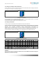
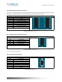
CANopen IO Module
User’s Manual
CANOPEN-16DI-16DO-6AIx-4AOx-2E
CANopen IO Module User’s Manual
!!! Warning!!!
Cybelec reserves the right to change any information contained in this manual without notice.
April 2005
Issue 1.0
2
CANopen IO Module User’s Manual
Content
PAGE
REFERENCE .................................................................................................................................................. 6
DEFINITIONS ............................................................................................................................................... 6
GENERAL INFORMATION .......................................................................................................................... 7
3.1
MANUAL HISTORY............................................................................................................................. 7
3.2
SAFETY GUIDELINES ......................................................................................................................... 7
3.2.1 Introduction ........................................................................................................................................... 7
3.2.2 Intended Use ......................................................................................................................................... 7
3.2.3 Transport and Storage ........................................................................................................................... 7
3.2.4 Installation ............................................................................................................................................. 7
3.3
IO MODULE CONFIGURATION TABLE........................................................................................... 8
4
TECHNICAL DATA ....................................................................................................................................... 9
4.1
GENERAL INFORMATION................................................................................................................. 9
4.1.1 Features.................................................................................................................................................. 9
4.2
IO MODULE INTERFACES............................................................................................................... 10
4.2.1 Power Supply ....................................................................................................................................... 10
4.2.2 Field Bus Connection ........................................................................................................................... 10
4.2.3 Display Elements.................................................................................................................................. 10
4.2.4 Setting the IO Module Address (Module ID) ....................................................................................... 11
4.2.5 Setting the Baud Rate .......................................................................................................................... 11
4.2.6 Digital Input and Output Connectors .................................................................................................. 12
4.2.7 Analog Input and Output Connector................................................................................................... 12
4.2.8 Encoder Input Connectors................................................................................................................... 12
5
CANOPEN-16DI-16DO-6AIx-4AOx-2E ....................................................................................................... 13
5.1
Technical Data .................................................................................................................................... 14
5.2
Dimensions.......................................................................................................................................... 15
6
MOUNTING ................................................................................................................................................ 16
6.1
MOUNTING INSTRUCTIONS.......................................................................................................... 16
6.2
SPACING ............................................................................................................................................ 16
7
NETWORK TOPOLOGY ............................................................................................................................. 17
8
NETWORK INITIALISATION AND SYSTEM BOOT-UP .......................................................................... 18
8.1
NMT STATE MACHINE .................................................................................................................... 18
8.2
INITIALISATION PROCEDURE ....................................................................................................... 18
9
OBJECT DESCRIPTION ............................................................................................................................. 19
9.1
Digital Input Module........................................................................................................................... 19
9.2
Digital Output Module ........................................................................................................................ 20
9.3
Analogue Input Module ...................................................................................................................... 21
9.4
Analogue Output Module.................................................................................................................... 22
10
OBJECT DICTIONARY .......................................................................................................................... 23
10.1
GENRAL INFORMATION OBJECTS ................................................................................................ 23
10.1.1 – Object 1000h: Device Type ............................................................................................................. 23
10.1.2 – Object 1001h: Error Register .......................................................................................................... 23
10.1.3 – Object 1003h: Pre-defined Error Field............................................................................................ 23
10.1.4 – Object 1008h: Manufacturer Device Name ..................................................................................... 24
10.1.5 – Object 1009h: Manufacturer Hardware Version.............................................................................. 24
10.1.6 – Object 100Ah: Manufacturer Software Version ............................................................................... 24
10.1.7 – Object 1017h: Producer Heartbeat time ......................................................................................... 24
10.1.8 – Object 1018h: Identity Object ......................................................................................................... 24
10.2
SYNC OBJECTS.................................................................................................................................. 26
10.2.1 – Object 1005h: COB-ID SYNC ......................................................................................................... 26
10.2.2 – Object 1006h: Communication Cycle Period .................................................................................. 26
10.2.3 – Object 1007h: Synchronous Windows Length ................................................................................. 26
10.3
EMERGENCY OBJECTS .................................................................................................................... 27
10.3.1 – Object 1014h: COB-ID EMCY ........................................................................................................ 27
10.3.2 – Object 1015h: Inhibit Time Emergency .......................................................................................... 27
10.4
PDO OBJECTS ................................................................................................................................... 28
10.4.1 – Object 1400h: Receive PDO Communication Parameter ................................................................ 28
10.4.2 – Object 1401h: Receive PDO Communication Parameter ................................................................ 28
1
2
3
3
CANopen IO Module User’s Manual
10.4.3 – Object 1404h: Receive PDO Communication Parameter ................................................................ 29
10.4.4 – Object 1600h: Receive PDO Mapping Parameter ........................................................................... 29
10.4.5 – Object 1601h: Receive PDO Mapping Parameter ........................................................................... 30
10.4.6 – Object 1604h: Receive PDO Mapping Parameter ........................................................................... 30
10.4.7 – Object 1800h: Transmit PDO Communication Parameter.............................................................. 31
10.4.8 – Object 1801h: Transmit PDO Communication Parameter.............................................................. 31
10.4.9 – Object 1802h: Transmit PDO Communication Parameter.............................................................. 32
10.4.10 – Object 1804h: Transmit PDO Communication Parameter............................................................ 32
10.4.11 – Object 1805h: Transmit PDO Communication Parameter............................................................ 33
10.4.12 – Object 1A00h: Transmit PDO Mapping Parameter ...................................................................... 33
10.4.13 – Object 1A01h: Transmit PDO Mapping Parameter ...................................................................... 34
10.4.14 – Object 1A02h: Transmit PDO Mapping Parameter ...................................................................... 34
10.4.15 – Object 1A04h: Transmit PDO Mapping Parameter ...................................................................... 35
10.4.16 – Object 1A05h: Transmit PDO Mapping Parameter ...................................................................... 35
10.5
MANUFACTURER DEVICE PROFILE .............................................................................................. 37
10.5.1 – Object 2000h: Operating Parameters Axis ...................................................................................... 37
10.5.2 – Object 2001h: Overflow Counter..................................................................................................... 39
10.5.3 – Object 2010h: Preset Value for Multi Sensor Device 32Bits ............................................................ 39
10.5.4 – Object 2020h: Position for Multi Sensor Devices 32Bits.................................................................. 39
10.5.5 – Object 2030h: Speed Value 16Bits .................................................................................................. 40
10.6
DEVICE PROFILE FOR GENERIC IO MODULE ............................................................................. 41
10.6.1 – Object 6000h: Read State 8 Input Lines.......................................................................................... 41
10.6.2 – Object 6002h: Polarity 8 Input Lines .............................................................................................. 41
10.6.3 – Object 6005h: Enable Digital input Interrupts................................................................................ 42
10.6.4 – Object 6006h: Input Interrupt Mask 8 – any change ...................................................................... 42
10.6.5 – Object 6007h: Input Interrupt Mask 8 – low to high....................................................................... 42
10.6.6 – Object 6008h: Input Interrupt Mask 8 – high to low....................................................................... 43
10.6.7 – Object 6020h: Read State 1 Input Line 1-16 ................................................................................... 43
10.6.8 – Object 6030h: Polarity 1 Input Line 1-16........................................................................................ 44
10.6.9 – Object 6050h: Interrupt Mask 1 Input Line 1-16 – any change ...................................................... 44
10.6.10 – Object 6060h: Interrupt Mask 1 Input Line 1-16 – low to high .................................................... 45
10.6.11 – Object 6070h: Interrupt Mask 1 Input Line 1-16 – high to low .................................................... 45
10.6.12 – Object 6200h: Write State 8 Output Lines..................................................................................... 46
10.6.13 – Object 6202h: Polarity 8 Output Lines.......................................................................................... 46
10.6.14 – Object 6206h: Fault Mode 8 Output Lines.................................................................................... 46
10.6.15 – Object 6207h: Fault State 8 Output Lines ..................................................................................... 47
10.6.16 – Object 6220h: Write State 1 Output Line 1-16 .............................................................................. 47
10.6.17 – Object 6401h: Read Analog Input 12 Bits ..................................................................................... 48
10.6.18 – Object 6411h: Write Analog Output 12 Bits.................................................................................. 48
10.6.19 – Object 6421h: Analog Input Interrupt Trigger Selection.............................................................. 49
10.6.20 – Object 6422h: Analog Interrupt Source ........................................................................................ 49
10.6.21 – Object 6423h: Global Analog Interrupt Enable............................................................................. 50
10.6.22 – Object 6424h: Analog Input Interrupt Upper Limit ..................................................................... 50
– Object 6425h: Analog Input Interrupt Lower Limit .................................................................................. 50
10.6.23 – Object 6426h: Analog Input Interrupt Delta................................................................................. 51
10.6.24 – Object 6443h: Analog Output Fault Mode .................................................................................... 51
10.6.25 – Object 6444h: Default Analog Output Fault State Unconverted ................................................... 52
10.6.26 – Object 67FEh: Error Behavior....................................................................................................... 52
10.6.27 – Object 67FFh: Device Type for multi profile devices .................................................................... 53
11
ACCESSORIES......................................................................................................................................... 54
11.1
OVERVIEW ......................................................................................................................................... 54
11.2
POWER SUPPLY PLUG...................................................................................................................... 54
11.2.1 General Information .......................................................................................................................... 54
11.2.2 Order Data......................................................................................................................................... 54
11.2.3 Technical Data ................................................................................................................................... 54
11.3
DIGITAL PLUG.................................................................................................................................. 55
11.3.1 General Information .......................................................................................................................... 55
11.3.2 Order Data......................................................................................................................................... 55
11.3.3 Technical Data ................................................................................................................................... 55
11.4
ANALOG PLUG.................................................................................................................................. 55
11.4.1 General Information .......................................................................................................................... 55
4
CANopen IO Module User’s Manual
11.4.2 Order Data......................................................................................................................................... 55
11.4.3 Technical Data ................................................................................................................................... 55
11.5
ENCODER INPUT PLUG .................................................................................................................. 56
11.5.1 Order Data......................................................................................................................................... 56
11.6
RJ45 CABLES...................................................................................................................................... 56
11.6.1 General Information .......................................................................................................................... 56
11.6.2 Order Data......................................................................................................................................... 56
11.6.3 Technical Data ................................................................................................................................... 56
12
NOTES..................................................................................................................................................... 57
5
CANopen IO Module User’s Manual
1
REFERENCE
CiA DS-301
Application Layer and Communication Profile Version 4.01
CiA DS-401
Device Profile for Generic IO Modules Version 2.1
CiA DS-406
Device Profile for Encoder Version 2.0
2
DEFINITIONS
CAN
Controller Area Network
CiA
CAN in Automation e. V. CAN-Bus international manufacturer and user organization
CAL
CAN Application Layer. The Application layer for CAN as specified by CiA
COB
Communication Object is a CAN message. Data must be sent across a CAN network
inside a COB.
COB-ID
COB-Identifier. Each CAN message has a single identifier. There are 2032 different
identifiers in a CAN network.
NMT
Network Management. One of the services of the application layer. It performs
initialization, configuration and error handling in a CAN network.
PDO
Process Data Object.
SDO
Service Data Object.
6
CANopen IO Module User’s Manual
3
3.1
GENERAL INFORMATION
MANUAL HISTORY
Revision
1.0
3.2
Date
14.03.2005
Comments
Preliminary revision, DBu
SAFETY GUIDELINES
3.2.1 Introduction
IO Modules devices have been designed developed or manufactured for conventional use in industry. They were
not designed, developed and manufactured for any use involving serious risks or hazards that without the
implementation of exceptionally stringent safety precautions could lead to death, injury, serious physical damage
or loss of any other kind. Such risks and hazards include in particular the use of these devices to monitor nuclear
reactions in nuclear power plants, as well as flight control systems, flight safety, the control of mass transportation
systems, medical life support systems, and the control of weapons systems.
When using IO Modules with programmable logic controllers and when using operating and monitoring devices
as control systems in conjunction with a Soft PLC, the safety precautions applying to industrial control systems
(e.g. the provision of safety devices such as emergency stop circuits, etc.) in accordance with applicable national
and international regulations must be observed. The same applies for all other devices connected to the system,
such as drives. All tasks such as installation, commissioning and service may only be carried out by qualified
personnel. Qualified personnel are persons who are familiar with the transport, mounting, installation,
commissioning and operation of the product and have the appropriate qualifications. National accident
prevention guidelines must be followed. The safety guidelines, connection descriptions and limit values listed in
the technical data must be read carefully before installation and commissioning and must be observed.
3.2.2 Intended Use
Electronic devices are generally not fail-safe. In the event of a failure on the IO Modules, operating or monitoring
device or uninterruptible power supply, the user is responsible for ensuring that other devices that may be
connected, such as motors, are made safe.
3.2.3 Transport and Storage
During transport and storage, devices must be protected from excessive stress (mechanical load, temperature,
humidity, aggressive atmosphere).
3.2.4 Installation
• The installation must take place according to the documentation.
• The IO Modules are only allowed to be installed without voltage applied and by qualified personnel.
• General safety regulations and nationally applicable accident prevention guidelines must be observed.
• Electrical installation must be carried out according to the relevant guidelines (e.g. line cross section, fuse,
protective ground connection).
7
CANopen IO Module User’s Manual
3.3
IO MODULE CONFIGURATION TABLE
Type
Description
Ordering key 2)
Bus Coupler
CANopen Bus Coupler
CANOPEN-
Digital IO
Analog IO
Encoder
Revision
xDI-
xDO-
xAI
x-
xAO
x-
8 DI 24VDC - 8DO 24VDC 3A
8
8
16 DI 24VDC
16
0
16 DO 24VDC 3A
0
16
16 DI 24VDC - 16DO 24VDC 3A
16
16
32 DI 24VDC
32
0
32 DO 24VDC 3A
0
32
none
0
1)
0
1)
6AD 12Bit - 4DA 12Bit
6
1)
4
1)
12AD 12Bit
12
1)
0
1)
8DA 12Bit
0
1)
8
1)
xE-
None
0
2 Encoder Inputs
2
Configuration Table Revision Number
x
1.0
1) P for (O…10VDC) or N for (-10…10VDC)
2) Ordering key example: CANOPEN-16DI-16DO-6AIP-4AON-2E-1.0
Option available today
Option that may be available in the future
Table: IO Module Configuration table
8
CANopen IO Module User’s Manual
4
TECHNICAL DATA
4.1
GENERAL INFORMATION
The IO Module from Cybelec offers the flexibility of a modular IO system and provides a solution for a wide
range of applications. Thanks to the flat structure with a height of just 40mm, the module can also be used in
particularly low terminal boxes.
The IO Modules is more than a remote IO system; it is a complete control solution.
The main characteristics of the Cybelec IO Module are the followings:
•
•
•
•
Low cost.
Adaptable.
Flexible.
Powerful.
4.1.1 Features
24VDC Supply
Status
indication
Field bus
connection
DIP switch
for node ID
and baud rate
Fig: CANOPEN-16DI-16DO-6AIx-4AOIx-2E
The device is comprised of:
•
•
•
•
24VDC Supply connector.
Display elements (LEDs) for status display of the operation, the bus communication, as well as for fault
messages and diagnosis.
CAN bus and RS232 bus connector.
DIP switch for node ID and baud rate.
9
CANopen IO Module User’s Manual
4.2
IO MODULE INTERFACES
In the following section, a description is given for all interfaces and plugs which an IO Module can have.
4.2.1 Power Supply
Input voltage: 24VDC ± 15%.
The supply voltage is internally protected, so that the device cannot be damaged if there is an overload or if the
voltage supply is connected incorrectly.
Supply Voltage
Pin
1
2
Accessorie
1690420000
Description
24VDC
GND
Weidmüller Connector (BLZF 3.5/2)
Fig: Supply Voltage Connection
4.2.2 Field Bus Connection
Field Bus Connection
Pin
1
2
3
4
5
6
7
8
Description
CAN_H
CAN_L
GND
RS232_RX (In)
RS232_TX (Out)
GND
Fig: Field bus connector
4.2.3 Display Elements
The operating condition of the field bus device is signaled via LEDs.
Display Elements
LED
CAN_ERR
RUN
TX-OVERFL
RX-OVERFL
Description
Device generate an Error
Device state: Pre-operational (Blinking);
Operational(On), Stop Mode(Flashing)
CAN transmitter buffer is full.
CAN receiver buffer is full.
Fig: Display elements
10
CANopen IO Module User’s Manual
4.2.4 Setting the IO Module Address (Module ID)
The DIP switches are used both for setting the baud rate of the field bus device and for setting the module ID.
This module ID is necessary for calculating the COB IDs.
DIP Switch Configurator
Fig: Setting the device node address
The binary significance of the individual DIP switches increases according to the switch number, i.e. the module
ID 1 is set by DIP1=’ON’, the module ID 8 by DIP4=’ON’, etc.
The nodes of the Cybelec-IO-System can have module IDs from 1 to 127.
4.2.5 Setting the Baud Rate
The device supports 9 different Baud rates. DIP Switches are used to set the baud rate.
The device changes to the configuration mode using the set module ID=0 (all DIP switches off) with subsequent
power On. The current set baud rate is displayed in this status. The baud rate display is shown by the LED group
(CAN-ERR, RUN, TX-OVERFL, RX-OVERFL), whereby CAN-ERR=Switch1, RUN=Switch2, TXOVERFL=Switch3, RX-OVERFL=Switch4. The current set baud rate is displayed by the corresponding LEDs.
Now the new baud rate can be set using the DIP switch, by turning the corresponding DIP switches to ‘ON’.
The set configuration is saved by turning DIP8 to ‘ON’. Following saving, all four LEDs are turned ‘On’.
DIP Switch Configurator
Fig: Example: Saving the baud rate 125kBit
DIP
1 (LSB)
2
3
4
(MSB)
5
6
7
8
9
Function
Baud rate
Baud rate
Baud rate
1
MBit
0
0
0
800
kBit
1
0
0
500
kBit
0
1
0
250
kBit
1
1
0
125
kBit
0
0
1
100
kBit
1
0
1
50
kBit
0
1
1
20
kBit
1
1
1
10
kBit
0
0
0
is displayed
by LED
CAN-ERR
RUN
TX-OVERFL
Baud rate
0
0
0
0
0
0
0
0
1
RX-OVERFL
Acceptance
CAN Bus
Termination
off' -> 'on': Accepting the configuration settings
On -> Add a terminal resistor of 120 O to the CAN bus.
Once the baud rate setting is completed, switch off the operating voltage.
Caution!
Only the last IO module of a CANopen network need to set the CAN Bus Termination trough the
DIP Switch 9 (cf. Network Topology).
11
CANopen IO Module User’s Manual
4.2.6 Digital Input and Output Connectors
Input 1 (I1) and respectively Input 2 (I2) are connected to fast interrupt inputs. Those fast interrupts may be used
for latching or preloading positions with Encoder Inputs (cf. Manufacturer Device Profile).
Digital Input and Output Connectors
B1
24V
0V
Ix
Ox
B2
24V
0V
Ix
Ox
Description
24VDC
GND
24VDC Input (Typ: Sink)
24VDC Output (Typ: Source)
Description
24VDC
GND
24VDC Input (Typ: Sink)
24VDC Output (Typ: Source)
Fig: Digital Input and Output Connectors
4.2.7 Analog Input and Output Connector
Analog Input and Output Connector
B3
AIx
REF
0V
AOx
0V
Description
0..10 / ±10VDC Input 1)
10V Reference voltage
AGND
0..10 / ±10VDC 1)
AGND
Fig: Analog Input and Output Connector
1) Cf. to the “IO Module Configuration table”.
4.2.8 Encoder Input Connectors
Encoder Input Connectors (E1 - E2)
Pin
1
2
3
4
5
6
7
8
9
Description
GND
A\
B\
I\
5VDC
A
B
I
GND
Fig: Encoder Input Connectors
12
CANopen IO Module User’s Manual
5
CANOPEN-16DI-16DO-6AIx-4AOx-2E
Fig: CANOPEN-16DI-16DO-6AIx-4AOx-2E Front view
Fig: CANOPEN-16DI-16DO-6AIx-4AOx-2E Rear view
13
CANopen IO Module User’s Manual
5.1
Technical Data
Description
CANOPEN-16DI-16DO-6AIx-4AOx-2E
Digital Channels
16 inputs, 16 outputs
Analog Channels
6 inputs, 4 outputs
Encoder Interfaces
2 encoder inputs
Bus Interface
CAN IO Slave
Supply Voltage
24VDC
Digital Inputs
16
Rated Voltage
24VDC
Input Filter
No
Input Circuit
Additional Functions
Sink
2 Fast Interrupts Inputs, Protection against over-voltage
Digital Outputs
16
Rated Voltage
24VDC
Nominal Output Current
3A per Output
Total Current
Output Circuit
Output Protection
Additional Functions
Max.10A per Connector (B2L 3.5/20)
Source
Thermal cutoff for over-current or short circuit, Integrated protection for
switching inductances
Pulse width modulation, Overload current controlled by software
Analog Inputs
6
Input
0..10V / ±10V 1)
Digital Converter Resolution
12 Bit
Conversion Time
<1ms for all channels
Output Format
DWORD
Basic Accuracy
±0.25% at 25°C
Input Protection
Protection against over-voltage
Analog Outputs
4
Output
0..10V / ±10V (-25/+60mA) 1)
Digital Converter Resolution
12Bit
Conversion Time
<1ms for all channels
Basic Accuracy
±0.25% at 25°C
Output Protection
No
Encoder Inputs
2
Encoder connections
AA\,BB\,II\
Sensor supply voltage
5 VDC (Max. 100mA / per Encoder)
Bit width
32 Bit
Maximum frequency
75 Mhz
Additional Functions
Latch, Preload, (cf. Manufacturer Device Profile)
Interface
Field bus interface
CAN IO Slave
Wiring
RJ45 S/STP Cat.5
Maximum Baud Rate
1 Mbit/s
General Information
Certification
(CE)
Status Display
IO function for each channel, status
Diagnostics
IO Function
Yes, with LEDs
CAN Interface
Yes, with LEDs
14
CANopen IO Module User’s Manual
Mechanical Characteristics
Dimensions in mm (WxHxD)
112x116x26.1
Weight
xxx g
Protection
IP 40
Operating/Storage Temperature
0 to 50°C / -20 to +70°C
Humidity
5 - 95%, non-condensing
Table: CANOPEN-16DI-16DO-6AIx-4AOx-2E
1) Cf. to the “IO Module Configuration table” to order the corresponding device.
5.2
Dimensions
Fig: CANOPEN-16DI-16DO-6AIx-4AOx-2E Dimensions in mm
15
CANopen IO Module User’s Manual
6
MOUNTING
6.1
MOUNTING INSTRUCTIONS
The IO Module can be snapped directly onto a carrier rail in accordance with the European standard EN 50022
(DIN35).
Carrier rails have different mechanical and electrical properties. For the optimal system setup on a carrier rail,
certain marginal terms must be observed.
•
The material must be non-corrosive.
•
Most components have a contact to the carrier rail to ground electro-magnetic disturbances. In order to
avoid corrosion, this tin-plated carrier rail contact must not form a galvanic cell with the material of the
carrier rail which generates a differential voltage above 0.5V.
•
The carrier rail must optimally support the EMC measures integrated into the system and the shielding
of the IO Module connections.
•
A sufficiently stable carrier rail should be selected and, if necessary, several assembly points (every 20 cm)
should be used in order to prevent bending and twisting (torsion).
•
The geometry of the carrier rail must not be altered in order to secure the safe hold of the components.
In particular, when shortening or mounting the carrier rail, it must not be crushed or bent…
6.2
SPACING
The spacing between adjacent components, cable conduits, casing and frame sides must be maintained for each
IO Module.
0
min. 20
116
55.5
min. 20
112
Fig: Spacing in mm
16
CANopen IO Module User’s Manual
7
NETWORK TOPOLOGY
To build a simple CANopen network, you need a master (for example an ELITE device) and connection cables
(RJ45 S/STP Cat.5) in addition to CANOPEN IO Modules.
The CANopen Network is constructed as a line structure with matching resistors (120 Ohm). In systems having
more than two stations, all subscribers are wired in parallel.
All net subscribers communicate at the same baud rate. In the network, all IO Modules nodes operate as slaves.
The master operation is taken over by a central control system, such as the ELITE device.
CAN Network are terminated
with a 120 Ohm resitor inside the
ELITE device.
RJ45 S/STP Cat.5 Cable
The CAN Network must be
terminated with a 120 Ohm resistor
trough the DIP switch 9 (ON) on the
last IO module of the CAN Network.
Fig: Network Topology
Caution!
Take care that you have set correctly all node ID and baud rate for each IO Module on the
CANopen Network.
17
CANopen IO Module User’s Manual
8
NETWORK INITIALISATION AND SYSTEM BOOT-UP
8.1
NMT STATE MACHINE
8.2
INITIALISATION PROCEDURE
18
CANopen IO Module User’s Manual
9
OBJECT DESCRIPTION
9.1
Digital Input Module
There are different access methods defined.
The following table lists the objects for 8-bit access.
Index
6000h
6001h
6002h
6003h
6004h
6005h
6006h
6007h
6008h
Object Code
Array
Array
Array
Var
Array
Array
Array
Name
Read State 8 Input Lines
Reserved
Polarity 8 Input Lines
Filter Constant 8 Input Lines (Not Implemented)
Reserved
Enable Digital Input Interrupts
Input Interrupt Mask 8 – any change
Input Interrupt Mask 8 – low to high
Input Interrupt Mask 8 – high to low
The Figure shows the relationship between the digital input objects for an 8-bit access.
19
Data Type
Unsigned8
Unsigned8
Unsigned8
Unsigned8
Unsigned8
Unsigned8
Unsigned8
CANopen IO Module User’s Manual
9.2
Digital Output Module
There are different access methods defined.
The following table lists the objects for 8-bit access.
Index
6200h
6201h
6202h
6203h
6204h
6205h
6206h
6207h
6208h
Object Code
Array
Array
Array
Array
Array
Name
Write State 8 Output Lines
Reserved
Polarity 8 Output Lines
Reserved
Reserved
Reserved
Fault Mode 8 Output Lines
Fault State 8 Output Lines
Filter Constant 8 Output Lines (Not Implemented)
The Figure shows the relationship between the digital output objects for an 8-bit access.
20
Data Type
Unsigned8
Unsigned8
Unsigned8
Unsigned8
Unsigned8
CANopen IO Module User’s Manual
9.3
Analogue Input Module
There are different access methods defined.
The following table lists the objects for 16-bit access.
Index
6401h
6421h
6422h
6423h
6424h
6425h
6426h
Object Code
Array
Array
Array
Var
Array
Array
Array
Name
Read Analog Input 12 Bits
Analog Input Interrupt Trigger Selection
Analog Interrupt Source
Global Analog Interrupt Enable
Analog Input Interrupt Upper Limit
Analog Input Interrupt Lower Limit
Analog Input Interrupt Delta
The Figure shows the relationship between the analogue input objects for a 16-bit access.
21
Data Type
Integer16
Unsigned8
Unsigned32
Unsigned8
Integer32
Integer32
Integer32
CANopen IO Module User’s Manual
9.4
Analogue Output Module
There are different access methods defined.
The following table lists the objects for 16-bit access.
Index
6411h
6443h
6444h
Object Code
Array
Array
Array
Name
Write Analog Output 12 Bits
Analog Output Fault Mode
Default Analog Output Fault State unconverted
The Figure shows the relationship between the analogue input objects for a 16-bit access.
22
Data Type
Integer16
Unsigned8
Intgerer32
CANopen IO Module User’s Manual
10 OBJECT DICTIONARY
10.1 GENRAL INFORMATION OBJECTS
10.1.1 – Object 1000h: Device Type
The device type specifies the kind of device. The lower 16 bit contains the device profile number and the upper 16
bit additional information.
INDEX
NAME
Object Code
Data Type
Access
PDO Mapping
Default Value
1000h
Device Type
VAR
Unsigned32
RO
No
0x000F0191
10.1.2 – Object 1001h: Error Register
The error register is a field of 8 bits, each for a certain error type. If an error occurs the bit has to be set.
INDEX
NAME
Object Code
Data Type
Access
PDO Mapping
Default Value
1001h
Error Register
VAR
Unsigned8
RO
No
0x00
Bit Number
0
1
2
3
4
5
6
7
Description
Generic Error
Communication error (overrun, error state)
device profile specific
Reserved
manufacturer specific
10.1.3 – Object 1003h: Pre-defined Error Field
This object holds errors that have occurred on the device and have been signaled via Emergency Object. It is an
error history. Writing to sub index 0 deletes the entire error history.
INDEX
NAME
Object Code
Number of Elements
1003h
Pre-defined Error Field
ARRAY
9
SUB-INDEX
NAME
Data Type
Access
PDO Mapping
Default Value
0
Number of Errors
Unsigned32
RW
No
0x00000000
SUB-INDEX
NAME
Data Type
Access
PDO Mapping
Default Value
1-8
Standard Error Field 1-8
Unsigned32
RO
No
0x00000000
23
CANopen IO Module User’s Manual
10.1.4 – Object 1008h: Manufacturer Device Name
Contains the device name.
INDEX
NAME
Object Code
Data Type
Access
PDO Mapping
Default Value
1008h
Manufacturer Device Name
VAR
Visible String
RO
No
CANOPEN-16DI-16DO-6AIx-4AOx-2E 1)
1) Cf. to the “IO Module Configuration table”.
10.1.5 – Object 1009h: Manufacturer Hardware Version
Contains the device hardware version.
INDEX
NAME
Object Code
Data Type
Access
PDO Mapping
1009h
Manufacturer Hardware version
VAR
Visible String
RO
No
10.1.6 – Object 100Ah: Manufacturer Software Version
Contains the device software version.
INDEX
NAME
Object Code
Data Type
Access
PDO Mapping
100Ah
Manufacturer Software version
VAR
Visible String
RO
No
10.1.7 – Object 1017h: Producer Heartbeat time
The producer heartbeat time defines the cycle time of the heartbeat. If the time is 0 it is not used. The time has to
be a multiple of 1 msec
INDEX
NAME
Object Code
Data Type
Access
PDO Mapping
Default Value
1017h
Producer Heartbeat time
VAR
Unsigned16
RW
No
0x0000
10.1.8 – Object 1018h: Identity Object
This object contains general information about the device.
Sub-Index 1 contains a unique value allocated to each manufacturer.
Sub-Index 2 identifies the manufacturer specific product code (device version).
Sub-Index 3 contains the revision number. Bit 31-16 is the major revision number and Bit 15-0 the minor revision
number.
Sub-Index 4 identified a manufacturer specific serial number.
INDEX
NAME
Object Code
Number of Elements
1018h
Identity Object
ARRAY
4
SUB-INDEX
NAME
Data Type
1
Vendor ID
Unsigned32
24
CANopen IO Module User’s Manual
Access
PDO Mapping
Default Value
RO
No
0x00000000
SUB-INDEX
NAME
Data Type
Access
PDO Mapping
Default Value
2
Product Code
Unsigned32
RO
No
0x00000000
SUB-INDEX
NAME
Data Type
Access
PDO Mapping
Default Value
3
Revision Number
Unsigned32
RO
No
0x00000000
SUB-INDEX
NAME
Data Type
Access
PDO Mapping
Default Value
4
Serial Number
Unsigned32
RO
No
0x00000000
25
CANopen IO Module User’s Manual
10.2 SYNC OBJECTS
10.2.1 – Object 1005h: COB-ID SYNC
COB-ID of the Synchronization object. If bit 31 is set the device consumes SYNC message and if bit 30 is set the
device produce SYNC message. The meaning of other bits is equal to the other communication objects.
INDEX
NAME
Object Code
Data Type
Access
PDO Mapping
Default Value
10058h
COB-ID SYNC
VAR
Unsigned32
RW
No
0x80000080
10.2.2 – Object 1006h: Communication Cycle Period
This entry defines the communication cycle period in µs. It is 0, if not used.
INDEX
NAME
Object Code
Data Type
Access
PDO Mapping
Default Value
1006h
Communication Cycle Period
VAR
Unsigned32
RW
No
0x00000000
10.2.3 – Object 1007h: Synchronous Windows Length
It contains the length of the time window for synchronous messages in µs. It is 0, if not used.
INDEX
NAME
Object Code
Data Type
Access
PDO Mapping
Default Value
1007h
Synchronous Windows Length
VAR
Visible String
RW
No
0x00000000
26
CANopen IO Module User’s Manual
10.3 EMERGENCY OBJECTS
10.3.1 – Object 1014h: COB-ID EMCY
COB-ID used for emergency message (Emergency Server).
INDEX
NAME
Object Code
Data Type
Access
PDO Mapping
Default Value
1014h
COB-ID EMCY
VAR
Unsigned32
RW
No
80h + Node-ID
10.3.2 – Object 1015h: Inhibit Time Emergency
Inhibit Time used for emergency message (Emergency Server).
The time has to be a multiple of 100 msec.
INDEX
NAME
Object Code
Data Type
Access
PDO Mapping
Default Value
1015h
Inhibit Time Emergency
VAR
Unsigned16
RW
No
0x0000
27
CANopen IO Module User’s Manual
10.4 PDO OBJECTS
10.4.1 – Object 1400h: Receive PDO Communication Parameter
It contains the communication parameters of the first PDO the device is able to receive.
Sub-index 0 contains the number of PDO-parameters implemented. Sub index 1 describes the COB-ID. If bit 31 is
set the PDO is disabled. The transmission mode is defined by sub-index 2.
An inhibit time can be defined on sub-index 3 in 100 µs.
INDEX
NAME
Object Code
Number of Elements
1400h
1st Receive PDO Communication Parameter (RPDO1)
ARRAY
3
SUB-INDEX
NAME
Data Type
Access
PDO Mapping
Default Value
1
COB-ID
Unsigned32
RW
No
0x200h + Node-ID
SUB-INDEX
NAME
Data Type
Access
PDO Mapping
Default Value
2
Transmission Type
Unsigned8
RW
No
0x01
SUB-INDEX
NAME
Data Type
Access
PDO Mapping
Default Value
3
Inhibit Time
Unsigned16
RW
No
0x0000
10.4.2 – Object 1401h: Receive PDO Communication Parameter
It contains the communication parameters of the first PDO the device is able to receive.
Sub-index 0 contains the number of PDO-parameters implemented. Sub index 1 describes the COB-ID. If bit 31 is
set the PDO is disabled. The transmission mode is defined by sub-index 2.
An inhibit time can be defined on sub-index 3 in 100 µs.
INDEX
NAME
Object Code
Number of Elements
1401h
2nd Receive PDO Communication Parameter (RPDO2)
ARRAY
3
SUB-INDEX
NAME
Data Type
Access
PDO Mapping
Default Value
1
COB-ID
Unsigned32
RW
No
0x300h + Node-ID
SUB-INDEX
NAME
Data Type
Access
PDO Mapping
Default Value
2
Transmission Type
Unsigned8
RW
No
0x01
SUB-INDEX
NAME
Data Type
Access
3
Inhibit Time
Unsigned16
RW
28
CANopen IO Module User’s Manual
PDO Mapping
Default Value
No
0x0000
10.4.3 – Object 1404h: Receive PDO Communication Parameter
It contains the communication parameters of the first PDO the device is able to receive.
Sub-index 0 contains the number of PDO-parameters implemented. Sub index 1 describes the COB-ID. If bit 31 is
set the PDO is disabled. The transmission mode is defined by sub-index 2.
An inhibit time can be defined on sub-index 3 in 100 µs.
!!Only first 4 pdo have predefined cob!!
INDEX
NAME
Object Code
Number of Elements
1404h
5 Receive PDO Communication Parameter (RPDO5)
ARRAY
3
SUB-INDEX
NAME
Data Type
Access
PDO Mapping
Default Value
1
COB-ID
Unsigned32
RW
No
0x500h + Node-ID
SUB-INDEX
NAME
Data Type
Access
PDO Mapping
Default Value
2
Transmission Type
Unsigned8
RW
No
0x01
SUB-INDEX
NAME
Data Type
Access
PDO Mapping
Default Value
3
Inhibit Time
Unsigned16
RW
No
0x0000
10.4.4 – Object 1600h: Receive PDO Mapping Parameter
It contains the mapping parameters of the first PDO the device is able to receive.
Sub-index 0 contains the number of the mapped data objects. All further entries define the data by its index, subindex and length.
INDEX
NAME
Object Code
Number of Elements
1600h
1st Receive PDO Mapping Parameter (RPDO1)
ARRAY
1..2
SUB-INDEX
NAME
Data Type
Access
PDO Mapping
Default Value
1
1st mapped Object
Unsigned32
RW
No
0x62000108 Digital Output 1-8
SUB-INDEX
NAME
Data Type
Access
PDO Mapping
Default Value
2
2nd mapped Object
Unsigned32
RW
No
0x62000208 Digital Output 9-16
29
CANopen IO Module User’s Manual
10.4.5 – Object 1601h: Receive PDO Mapping Parameter
It contains the mapping parameters of the first PDO the device is able to receive.
Sub-index 0 contains the number of the mapped data objects. All further entries define the data by its index, subindex and length.
INDEX
NAME
Object Code
Number of Elements
1601h
2nd Receive PDO Mapping Parameter (RPDO2)
ARRAY
1..4
SUB-INDEX
NAME
Data Type
Access
PDO Mapping
Default Value
1
1st mapped Object
Unsigned32
RW
No
0x64110110 Analog Output 1
SUB-INDEX
NAME
Data Type
Access
PDO Mapping
Default Value
2
2nd mapped Object
Unsigned32
RW
No
0x64110210 Analog Output 2
SUB-INDEX
NAME
Data Type
Access
PDO Mapping
Default Value
3
3rd mapped Object
Unsigned32
RW
No
0x64110310 Analog Output 3
SUB-INDEX
NAME
Data Type
Access
PDO Mapping
Default Value
4
4 mapped Object
Unsigned32
RW
No
0x64110410 Analog Output 4
10.4.6 – Object 1604h: Receive PDO Mapping Parameter
It contains the mapping parameters of the first PDO the device is able to receive.
Sub-index 0 contains the number of the mapped data objects. All further entries define the data by it's index, subindex and length.
INDEX
NAME
Object Code
Number of Elements
1604h
5 Receive PDO Mapping Parameter (RPDO5)
ARRAY
1..2
SUB-INDEX
NAME
Data Type
Access
PDO Mapping
Default Value
1
1st mapped Object
Unsigned32
RW
No
0x20000208 Control Axis 1 Byte
SUB-INDEX
NAME
Data Type
Access
PDO Mapping
Default Value
2
2nd mapped Object
Unsigned32
RW
No
0x20000408 Control Axis 2 Byte
30
CANopen IO Module User’s Manual
10.4.7 – Object 1800h: Transmit PDO Communication Parameter
It contains the communication parameters of the first PDO the device is able to transmit.
Sub-index 0 contains the number of PDO-parameters implemented. Sub index 1 describes the COB-ID. If bit 31 is
set the PDO is disabled. The transmission mode is defined by sub-index 2.
An inhibit time can be defined on sub-index 3 in 100 µs.
INDEX
NAME
Object Code
Number of Elements
1800h
1st Transmit PDO Communication Parameter (TPDO1)
ARRAY
3
SUB-INDEX
NAME
Data Type
Access
PDO Mapping
Default Value
1
COB-ID
Unsigned32
RW
No
0x180h + Node-ID
SUB-INDEX
NAME
Data Type
Access
PDO Mapping
Default Value
2
Transmission Type
Unsigned8
RW
No
0x01
SUB-INDEX
NAME
Data Type
Access
PDO Mapping
Default Value
3
Inhibit Time
Unsigned16
RW
No
0x0000
10.4.8 – Object 1801h: Transmit PDO Communication Parameter
It contains the communication parameters of the second PDO the device is able to transmit.
Sub-index 0 contains the number of PDO-parameters implemented. Sub index 1 describes the COB-ID. If bit 31 is
set the PDO is disabled. The transmission mode is defined by sub-index 2.
An inhibit time can be defined on sub-index 3 in 100 µs.
INDEX
NAME
Object Code
Number of Elements
1801h
2nd Transmit PDO Communication Parameter (TPDO2)
ARRAY
3
SUB-INDEX
NAME
Data Type
Access
PDO Mapping
Default Value
1
COB-ID
Unsigned32
RW
No
0x280h + Node-ID
SUB-INDEX
NAME
Data Type
Access
PDO Mapping
Default Value
2
Transmission Type
Unsigned8
RW
No
0x01
SUB-INDEX
NAME
Data Type
Access
PDO Mapping
3
Inhibit Time
Unsigned16
RW
No
31
CANopen IO Module User’s Manual
10.4.9 – Object 1802h: Transmit PDO Communication Parameter
It contains the communication parameters of the actual PDO the device is able to transmit.
Sub-index 0 contains the number of PDO-parameters implemented. Sub index 1 describes the COB-ID. If bit 31 is
set the PDO is disabled. The transmission mode is defined by sub-index 2.
An inhibit time can be defined on sub-index 3 in 100 µs.
INDEX
NAME
Object Code
Number of Elements
1802h
3rd Transmit PDO Communication Parameter (TPDO3)
ARRAY
3
SUB-INDEX
NAME
Data Type
Access
PDO Mapping
Default Value
1
COB-ID
Unsigned32
RW
No
0x380h + Node-ID
SUB-INDEX
NAME
Data Type
Access
PDO Mapping
Default Value
2
Transmission Type
Unsigned8
RW
No
0x01
SUB-INDEX
NAME
Data Type
Access
PDO Mapping
3
Inhibit Time
Unsigned16
RW
No
10.4.10 – Object 1804h: Transmit PDO Communication Parameter
It contains the communication parameters of the actual PDO the device is able to transmit.
Sub-index 0 contains the number of PDO-parameters implemented. Sub index 1 describes the COB-ID. If bit 31 is
set the PDO is disabled. The transmission mode is defined by sub-index 2.
An inhibit time can be defined on sub-index 3 in 100 µs.
!!Only first 4 pdo have predefined cob!!
INDEX
NAME
Object Code
Number of Elements
1804h
5 Transmit PDO Communication Parameter (TPDO5)
ARRAY
3
SUB-INDEX
NAME
Data Type
Access
PDO Mapping
1
COB-ID
Unsigned32
RW
No
SUB-INDEX
NAME
Data Type
Access
PDO Mapping
Default Value
2
Transmission Type
Unsigned8
RW
No
0x01
SUB-INDEX
NAME
Data Type
Access
PDO Mapping
3
Inhibit Time
Unsigned16
RW
No
32
CANopen IO Module User’s Manual
10.4.11 – Object 1805h: Transmit PDO Communication Parameter
It contains the communication parameters of the actual PDO the device is able to transmit.
Sub-index 0 contains the number of PDO-parameters implemented. Sub index 1 describes the COB-ID. If bit 31 is
set the PDO is disabled. The transmission mode is defined by sub-index 2.
An inhibit time can be defined on sub-index 3 in 100 µs.
!!Only first 4 pdo have predefined cob!!
INDEX
NAME
Object Code
Number of Elements
1805h
6 Transmit PDO Communication Parameter (TPDO6)
ARRAY
3
SUB-INDEX
NAME
Data Type
Access
PDO Mapping
1
COB-ID
Unsigned32
RW
No
SUB-INDEX
NAME
Data Type
Access
PDO Mapping
Default Value
2
Transmission Type
Unsigned8
RW
No
0x01
SUB-INDEX
NAME
Data Type
Access
PDO Mapping
3
Inhibit Time
Unsigned16
RW
No
10.4.12 – Object 1A00h: Transmit PDO Mapping Parameter
It contains the mapping parameter for the PDOs the device is able to transmit.
Sub-index 0 contains the number of the mapped data objects. All further entries define the data by its index, subindex and length.
The structure of a mapping entry is:
INDEX
NAME
Object Code
Number of Elements
1A00h
1st Transmit PDO Mapping Parameter (TPDO1)
ARRAY
1..2
SUB-INDEX
NAME
Data Type
Access
PDO Mapping
Default Value
1
1st mapped Object
Unsigned32
RW
No
0x60000108 Digital Input 1-8
SUB-INDEX
NAME
Data Type
Access
PDO Mapping
Default Value
2
2nd mapped Object
Unsigned32
RW
No
0x60000208 Digital Input 9-16
33
CANopen IO Module User’s Manual
10.4.13 – Object 1A01h: Transmit PDO Mapping Parameter
It contains the mapping parameter for the PDOs the device is able to transmit.
Sub-index 0 contains the number of the mapped data objects. All further entries define the data by its index, subindex and length.
The structure of a mapping entry is:
INDEX
NAME
Object Code
Number of Elements
1A01h
2nd Transmit PDO Mapping Parameter (TPDO2)
ARRAY
1..4
SUB-INDEX
NAME
Data Type
Access
PDO Mapping
Default Value
1
1st mapped Object
Unsigned32
RW
No
0x64010110 Analog Input 1
SUB-INDEX
NAME
Data Type
Access
PDO Mapping
Default Value
2
2nd mapped Object
Unsigned32
RW
No
0x64010210 Analog Input 2
SUB-INDEX
NAME
Data Type
Access
PDO Mapping
Default Value
3
3rd mapped Object
Unsigned32
RW
No
0x64010310 Analog Input 3
SUB-INDEX
NAME
Data Type
Access
PDO Mapping
Default Value
4
4 mapped Object
Unsigned32
RW
No
0x64010410 Analog Input 4
10.4.14 – Object 1A02h: Transmit PDO Mapping Parameter
It contains the mapping parameter for the PDOs the device is able to transmit.
Sub-index 0 contains the number of the mapped data objects. All further entries define the data by it's index, subindex and length.
The structure of a mapping entry is:
INDEX
NAME
Object Code
Number of Elements
1A02h
3rd Transmit PDO Mapping Parameter (TPDO3)
ARRAY
1..2
SUB-INDEX
NAME
Data Type
Access
PDO Mapping
Default Value
1
1st mapped Object
Unsigned32
RW
No
0x64010510 Analog Input 5
SUB-INDEX
NAME
Data Type
Access
PDO Mapping
2
2nd mapped Object
Unsigned32
RW
No
34
CANopen IO Module User’s Manual
Default Value
0x64010610 Analog Input 6
10.4.15 – Object 1A04h: Transmit PDO Mapping Parameter
It contains the mapping parameter for the PDOs the device is able to transmit.
Sub-index 0 contains the number of the mapped data objects. All further entries define the data by its index, subindex and length.
The structure of a mapping entry is:
INDEX
NAME
Object Code
Number of Elements
1A04h
5 Transmit PDO Mapping Parameter (TPDO5)
ARRAY
1..3
SUB-INDEX
NAME
Data Type
Access
PDO Mapping
Default Value
1
1st mapped Object
Unsigned32
RW
No
0x20000108 Status Axis 1
SUB-INDEX
NAME
Data Type
Access
PDO Mapping
Default Value
2
2nd mapped Object
Unsigned32
RW
No
0x20200120 Position Axis 1
SUB-INDEX
NAME
Data Type
Access
PDO Mapping
Default Value
3
3rd mapped Object
Unsigned32
RW
No
0x20300110 Speed Axis 1
10.4.16 – Object 1A05h: Transmit PDO Mapping Parameter
It contains the mapping parameter for the PDOs the device is able to transmit.
Sub-index 0 contains the number of the mapped data objects. All further entries define the data by its index, subindex and length.
The structure of a mapping entry is:
INDEX
NAME
Object Code
Number of Elements
1A05h
6 Transmit PDO Mapping Parameter (TPDO6)
ARRAY
1..3
SUB-INDEX
NAME
Data Type
Access
PDO Mapping
Default Value
1
1st mapped Object
Unsigned32
RW
No
0x20000308 Status Axis 2
SUB-INDEX
NAME
Data Type
Access
PDO Mapping
Default Value
2
2nd mapped Object
Unsigned32
RW
No
0x20200220 Position Axis 2
SUB-INDEX
NAME
Data Type
3
3rd mapped Object
Unsigned32
35
CANopen IO Module User’s Manual
Access
PDO Mapping
Default Value
RW
No
0x20300210 Speed Axis 2
36
CANopen IO Module User’s Manual
10.5 MANUFACTURER DEVICE PROFILE
10.5.1 – Object 2000h: Operating Parameters Axis
This object contains the Status and Control Byte of Axis 1 & 2.
INDEX
NAME
Object Code
Number of Elements
2000h
Operating Parameters Axis
ARRAY
4
SUB-INDEX
NAME
Data Type
Access
PDO Mapping
1
Status Byte Axis 1
Unsigned8
RW
Yes
SUB-INDEX
NAME
Data Type
Access
PDO Mapping
2
Control Byte Axis 1
Unsigned8
RW
Yes
SUB-INDEX
NAME
Data Type
Access
PDO Mapping
3
Status Byte Axis 2
Unsigned8
RW
Yes
SUB-INDEX
NAME
Data Type
Access
PDO Mapping
4
Control Byte Axis 2
Unsigned8
RW
Yes
Satus Byte for Axis 1 (S1: Index:0x2000 Sub-Index:0x1)
Bit Description
0 LATC_VAL
1
LATC_EXT_VAL
2
CNT_SET_ACK
3
UNDERFLOW
4
OVERFLOW
5
6
7
Not used
Not used
Not used
Function
Acknowledge bit for EN_LATC (C1.0)
Latch Mode:
This bit is set with a positive edge at input I (Encoder Index Pulse)
It is reset when EN_LATC is reset
Preload Mode:
This bit is set with a positive edge at input I (Encoder Index Pulse)
It is reset when EN_LATC is reset
Acknowledge bit for EN_LATC_EXT (C1.1)
Latch Mode:
This bit is set with a positive edge at input I1 (Input Connector B1)
It is reset when EN_LATC is reset
Preload Mode:
This bit is set with a positive edge at input I1 (Input Connector B1)
It is reset when EN_LATC is reset
Acknowledge bit for CNT_SET (C1.2)
It is reset when CNT_SET is reset
UNDERFLOW=1 with a counter overflow of 0x00000000 to 0xFFFFFFFF
UNDERFLOW=0 if counter < 0xAAAAAAAA
UNDERFLOW=0 if positive edge on ResetUnderflow (C1.3)
UNDERFLOW=0 if OVERFLOW=1
OVERFLOW=1 with a counter overflow of 0xFFFFFFFF to 0x00000000
OVERFLOW=0 if counter < 0x55555555
OVERFLOW=0 if positive edge on ResetOverflow (C1.4)
OVERFLOW=0 if UNDERFLOW=1
37
CANopen IO Module User’s Manual
Control Byte for Axis 1 (C1: Index:0x2000 Sub-Index:0x2)
Bit Description
0 EN_LATC_VAL
1
EN_LATC_EXT
2
3
4
5
6
CNT_SET
RESET_UNDERFLOW
RESET_OVERFLOW
Not used
OPMODE
7
Not used
Function
The Encoder zero mark is released
Latch Mode:
With a positive edge at input I (Encoder Index Pulse) the counter reading
is transferred to the latch register (Object index 0x2010 Sub-index 1)
Preload Mode:
With a positive edge at input I (Encoder Index Pulse) the counter is
loaded with the set value (Object index 0x2010 Sub-index 1)
The confirmation is de-selected for the negative edge of EN_LATC
The external latch input is released
Latch Mode:
With a positive edge at input I1 (Input Connector B1) the counter reading
is transferred to the latch register (Object index 0x2010 Sub-index 1)
Preload Mode:
With a positive edge at input I1 (Input Connector B1) the counter is
loaded with the set value (Object index 0x2010 Sub-index 1)
The confirmation is de-selected for the negative edge of EN_LATC_EXT
With a positive edge, the counter is initialized on the set value (Object index 0x2010 Sub-index 1)
With a positive edge the status bit UNDERFLOW (S1.4) is reset
With a positive edge the status bit OVERFLOW (S1.5) is reset
0=Latch Mode
1=Preload Mode
The counter is latched by a trigger signal
The counter is loaded with the set value by a trigger signal
Satus Byte for Axis 2 (S2: Index:0x2000 Sub-Index:0x3)
Bit Description
0 LATC_VAL
1
LATC_EXT_VAL
2
CNT_SET_ACK
3
UNDERFLOW
4
OVERFLOW
5
6
7
Not used
Not used
Not used
Function
Acknowledge bit for EN_LATC (C2.0)
Latch Mode:
This bit is set with a positive edge at input I (Encoder Index Pulse)
It is reset when EN_LATC is reset
Preload Mode:
This bit is set with a positive edge at input I (Encoder Index Pulse)
It is reset when EN_LATC is reset
Acknowledge bit for EN_LATC_EXT (C2.1)
Latch Mode:
This bit is set with a positive edge at input I2 (Input Connector B1)
It is reset when EN_LATC is reset
Preload Mode:
This bit is set with a positive edge at input I2 (Input Connector B1)
It is reset when EN_LATC is reset
Acknowledge bit for CNT_SET (C2.2)
It is reset when CNT_SET is reset
UNDERFLOW=1 with a counter overflow of 0x00000000 to 0xFFFFFFFF
UNDERFLOW=0 if counter < 0xAAAAAAAA
UNDERFLOW=0 if positive edge on ResetUnderflow (C2.3)
UNDERFLOW=0 if OVERFLOW=1
OVERFLOW=1 with a counter overflow of 0xFFFFFFFF to 0x00000000
OVERFLOW=0 if counter < 0x55555555
OVERFLOW=0 if positive edge on ResetOverflow (C2.4)
OVERFLOW=0 if UNDERFLOW=1
Control Byte for Axis 2 (C2: Index:0x2000 Sub-Index:0x4)
Bit Description
0 EN_LATC_VAL
1
EN_LATC_EXT
2
3
4
5
6
CNT_SET
RESET_UNDERFLOW
RESET_OVERFLOW
Not used
OPMODE
7
Not used
Function
The Encoder zero mark is released
Latch Mode:
With a positive edge at input I (Encoder Index Pulse) the counter reading
is transferred to the latch register (Object index 0x2010 Sub-index 2)
Preload Mode:
With a positive edge at input I (Encoder Index Pulse) the counter is
loaded with the set value (Object index 0x2010 Sub-index 2)
The confirmation is de-selected for the negative edge of EN_LATC
The external latch input is released
Latch Mode:
With a positive edge at input I2 (Input Connector B1) the counter reading
is transferred to the latch register (Object index 0x2010 Sub-index 2)
Preload Mode:
With a positive edge at input I2 (Input Connector B1) the counter is
loaded with the set value (Object index 0x2010 Sub-index 2)
The confirmation is de-selected for the negative edge of EN_LATC_EXT
With a positive edge, the counter is initialized on the set value (Object index 0x2010 Sub-index 2)
With a positive edge the status bit UNDERFLOW (S2.4) is reset
With a positive edge the status bit OVERFLOW (S2.5) is reset
0=Latch Mode
1=Preload Mode
The counter is latched by a trigger signal
The counter is loaded with the set value by a trigger signal
38
CANopen IO Module User’s Manual
10.5.2 – Object 2001h: Overflow Counter
This parameter is the internal overflow counter. (16->32bits overflow counter)
INDEX
NAME
Object Code
Number of Elements
2001h
Overflow Counter
ARRAY
2
SUB-INDEX
NAME
Data Type
Access
PDO Mapping
1
Overflow Counter Axis 1
Integer32
RO
No
SUB-INDEX
NAME
Data Type
Access
PDO Mapping
2
Overflow Counter Axis 2
Integer32
RO
No
10.5.3 – Object 2010h: Preset Value for Multi Sensor Device 32Bits
This object contains the Preset position value for Axis 1 & Axis 2. The Data width is 32Bits
INDEX
NAME
Object Code
Number of Elements
2010h
Preset Value for Multi Sensor Device 32Bits
ARRAY
2
SUB-INDEX
NAME
Data Type
Access
PDO Mapping
1
Preset / Latch Value Axis 1
Unsigned32
RW
Yes
SUB-INDEX
NAME
Data Type
Access
PDO Mapping
2
Preset / Latch Value Axis 2
Unsigned32
RW
Yes
10.5.4 – Object 2020h: Position for Multi Sensor Devices 32Bits
This object contains the Output Position value for Axis 1 & Axis 2. The Data width is 32Bits
INDEX
NAME
Object Code
Number of Elements
2020h
Position for Multi Sensor Devices 32Bits
ARRAY
2
SUB-INDEX
NAME
Data Type
Access
PDO Mapping
1
Position Value Axis 1
Unsigned32
RO
Yes
SUB-INDEX
NAME
Data Type
Access
PDO Mapping
2
Position Value Axis 2
Unsigned32
RO
Yes
39
CANopen IO Module User’s Manual
10.5.5 – Object 2030h: Speed Value 16Bits
This object contains the Output speed value for Axis 1 & Axis 2. The Data width is 16Bits
INDEX
NAME
Object Code
Number of Elements
2030h
Speed Value 16Bits
ARRAY
2
SUB-INDEX
NAME
Data Type
Access
PDO Mapping
1
Speed Value Axis 1
Integer16
R=
Yes
SUB-INDEX
NAME
Data Type
Access
PDO Mapping
2
Speed Value Axis 2
Integer16
RO
Yes
40
CANopen IO Module User’s Manual
10.6 DEVICE PROFILE FOR GENERIC IO MODULE
10.6.1 – Object 6000h: Read State 8 Input Lines
Reads a group of 8 inputs lines as a byte of information.
INDEX
NAME
Object Code
Number of Elements
6000h
Read State 8 Input Lines
ARRAY
2
SUB-INDEX
NAME
Data Type
Access
PDO Mapping
0
Number of elements
Unsigned8
RO
No
SUB-INDEX
NAME
Data Type
Access
PDO Mapping
1
Digital Inputs 1-8
Unsigned8
RO
Yes
SUB-INDEX
NAME
Data Type
Access
PDO Mapping
2
Digital Inputs 9-16
Unsigned8
RO
Yes
10.6.2 – Object 6002h: Polarity 8 Input Lines
Defines the polarity of a group of 8 input lines.
INDEX
NAME
Object Code
Number of Elements
6002h
Polarity 8 Input Lines
ARRAY
2
SUB-INDEX
NAME
Data Type
Access
PDO Mapping
0
Number of elements
Unsigned8
RO
No
SUB-INDEX
NAME
Data Type
Access
PDO Mapping
1
Polarity for Digital Inputs 1-8
Unsigned8
RW
No
SUB-INDEX
NAME
Data Type
Access
PDO Mapping
2
Polarity for Digital Inputs 9-16
Unsigned8
RW
No
41
CANopen IO Module User’s Manual
10.6.3 – Object 6005h: Enable Digital input Interrupts
Globally enable or disable input interrupts.
INDEX
NAME
Object Code
Data Type
Access
PDO Mapping
Default Value
6005h
Enable Digital Input Interrupts
VAR
Unsigned8
RW
No
0x00
10.6.4 – Object 6006h: Input Interrupt Mask 8 – any change
Determines which input port lines activate an interrupt. Done for groups of 8 lines and for any change of a digital
input line. By default, every input activates an interrupt.
INDEX
NAME
Object Code
Number of Elements
6006h
Input Interrupt Mask 8 – any change
ARRAY
2
SUB-INDEX
NAME
Data Type
Access
PDO Mapping
0
Number of elements
Unsigned8
RO
No
SUB-INDEX
NAME
Data Type
Access
PDO Mapping
1
Input Interrupt Mask 8 – any change for Digital Inputs 1-8
Unsigned8
RW
No
SUB-INDEX
NAME
Data Type
Access
PDO Mapping
2
Input Interrupt Mask 8 – any change for Digital Inputs 9-16
Unsigned8
RW
No
10.6.5 – Object 6007h: Input Interrupt Mask 8 – low to high
Determines which input port lines activate an interrupt. Done for Groups of 8 lines and for a change from low to
high of a digital input line. The values are in 'OR' connection to the values of object 6006h.
INDEX
NAME
Object Code
Number of Elements
6007h
Input Interrupt Mask 8 – low to high
ARRAY
2
SUB-INDEX
NAME
Data Type
Access
PDO Mapping
0
Number of elements
Unsigned8
RO
No
SUB-INDEX
NAME
Data Type
Access
PDO Mapping
1
Input Interrupt Mask 8 – low to high for Digital Inputs 1-8
Unsigned8
RW
No
42
CANopen IO Module User’s Manual
SUB-INDEX
NAME
Data Type
Access
PDO Mapping
2
Input Interrupt Mask 8 – low to high for Digital Inputs 9-16
Unsigned8
RW
No
10.6.6 – Object 6008h: Input Interrupt Mask 8 – high to low
Determines which input port lines activate an interrupt. Done for groups of 8 lines and for a change from high to
low of a digital input line. The values are in an 'OR' connection to the values of object 6006h.
INDEX
NAME
Object Code
Number of Elements
6008h
Input Interrupt Mask 8 – high to low
ARRAY
2
SUB-INDEX
NAME
Data Type
Access
PDO Mapping
0
Number of elements
Unsigned8
RO
No
SUB-INDEX
NAME
Data Type
Access
PDO Mapping
1
Input Interrupt Mask 8 – high to low for Digital Inputs 1-8
Unsigned8
RW
No
SUB-INDEX
NAME
Data Type
Access
PDO Mapping
2
Input Interrupt Mask 8 – high to low for Digital Inputs 9-16
Unsigned8
RW
No
10.6.7 – Object 6020h: Read State 1 Input Line 1-16
Reads single input line information. A maximum of 16 bit inputs are addressable at one index.
INDEX
NAME
Object Code
Number of Elements
6020h
Read State 1 Input Line 1-16
ARRAY
16
SUB-INDEX
NAME
Data Type
Access
PDO Mapping
0
Number of elements
Unsigned8
RO
No
SUB-INDEX
NAME
Data Type
Access
PDO Mapping
1
Digital Input 1
Unsigned8
RO
Yes
to
SUB-INDEX
NAME
Data Type
Access
PDO Mapping
16
Digital Input 16
Unsigned8
RO
Yes
43
CANopen IO Module User’s Manual
10.6.8 – Object 6030h: Polarity 1 Input Line 1-16
Sets the polarity of a single input line. A maximum of 16 bit inputs are addressable at one index.
INDEX
NAME
Object Code
Number of Elements
6030h
Polarity 1 Input Line 1-16
ARRAY
16
SUB-INDEX
NAME
Data Type
Access
PDO Mapping
0
Number of elements
Unsigned8
RO
No
SUB-INDEX
NAME
Data Type
Access
PDO Mapping
1
Polarity Digital Input 1
Unsigned8
RW
Yes
to
SUB-INDEX
NAME
Data Type
Access
PDO Mapping
16
Polarity Digital Input 16
Unsigned8
RW
Yes
10.6.9 – Object 6050h: Interrupt Mask 1 Input Line 1-16 – any change
Sets the interrupt mask for 'any change' for a single input line. A maximum of 16 bit inputs are addressable at one
index.
INDEX
NAME
Object Code
Number of Elements
6050h
Interrupt Mask 1 Input Line 1-16 – any change
ARRAY
16
SUB-INDEX
NAME
Data Type
Access
PDO Mapping
0
Number of elements
Unsigned8
RO
No
SUB-INDEX
NAME
Data Type
Access
PDO Mapping
1
Interrupt Mask 1 Input Line 1-16 – any change for Digital Input 1
Unsigned8
RW
Yes
to
SUB-INDEX
NAME
Data Type
Access
PDO Mapping
16
Interrupt Mask 1 Input Line 1-16 – any change for Digital Input 16
Unsigned8
RW
Yes
44
CANopen IO Module User’s Manual
10.6.10 – Object 6060h: Interrupt Mask 1 Input Line 1-16 – low to high
Sets interrupt mask for a single input line. A maximum of 16 bit inputs are addressable at one index.
INDEX
NAME
Object Code
Number of Elements
6060h
Interrupt Mask 1 Input Line 1-16 – low to high
ARRAY
16
SUB-INDEX
NAME
Data Type
Access
PDO Mapping
0
Number of elements
Unsigned8
RO
No
SUB-INDEX
NAME
Data Type
Access
PDO Mapping
1
Interrupt Mask 1 Input Line 1-16 – low to high for Digital Input 1
Unsigned8
RW
Yes
to
SUB-INDEX
NAME
Data Type
Access
PDO Mapping
16
Interrupt Mask 1 Input Line 1-16 – low to high for Digital Input 16
Unsigned8
RW
Yes
10.6.11 – Object 6070h: Interrupt Mask 1 Input Line 1-16 – high to low
Sets interrupt mask for a single input line. A maximum of 16 bit inputs are addressable at one index.
INDEX
NAME
Object Code
Number of Elements
6070h
Interrupt Mask 1 Input Line 1-16 – high to low
ARRAY
16
SUB-INDEX
NAME
Data Type
Access
PDO Mapping
0
Number of elements
Unsigned8
RO
No
SUB-INDEX
NAME
Data Type
Access
PDO Mapping
1
Interrupt Mask 1 Input Line 1-16 – high to low for Digital Input 1
Unsigned8
RW
Yes
to
SUB-INDEX
NAME
Data Type
Access
PDO Mapping
16
Interrupt Mask 1 Input Line 1-16 – high to low for Digital Input 16
Unsigned8
RW
Yes
45
CANopen IO Module User’s Manual
10.6.12 – Object 6200h: Write State 8 Output Lines
Sets a group of 8 output lines as a byte of information.
INDEX
NAME
Object Code
Number of Elements
6200h
Write State 8 Output Lines
ARRAY
2
SUB-INDEX
NAME
Data Type
Access
PDO Mapping
0
Number of elements
Unsigned8
RO
No
SUB-INDEX
NAME
Data Type
Access
PDO Mapping
1
Digital Outputs 1-8
Unsigned8
RW
Yes
SUB-INDEX
NAME
Data Type
Access
PDO Mapping
2
Digital Outputs 9-16
Unsigned8
RW
Yes
10.6.13 – Object 6202h: Polarity 8 Output Lines
Defines the polarity of a group of 8 output lines.
INDEX
NAME
Object Code
Number of Elements
6202h
Polarity 8 Output Lines
ARRAY
2
SUB-INDEX
NAME
Data Type
Access
PDO Mapping
0
Number of elements
Unsigned8
RO
No
SUB-INDEX
NAME
Data Type
Access
PDO Mapping
1
Polarity for Digital Outputs 1-8
Unsigned8
RW
No
SUB-INDEX
NAME
Data Type
Access
PDO Mapping
2
Polarity for Digital Outputs 9-16
Unsigned8
RW
No
10.6.14 – Object 6206h: Fault Mode 8 Output Lines
Output line fault mode. This defines the default output mode on detecting a fault condition. Defined for groups
of 8 lines (1 bit per line). This equals 1 if the output must revert to a predefined output state on fault detection.
Default mode is that the outputs do revert to a predefined output state.
INDEX
NAME
Object Code
Number of Elements
6206h
Fault Mode 8 Output Lines
ARRAY
2
46
CANopen IO Module User’s Manual
SUB-INDEX
NAME
Data Type
Access
PDO Mapping
0
Number of elements
Unsigned8
RO
No
SUB-INDEX
NAME
Data Type
Access
PDO Mapping
1
Fault Mode for Digital Outputs 1-8
Unsigned8
RW
No
SUB-INDEX
NAME
Data Type
Access
PDO Mapping
2
Fault Mode for Digital Outputs 9-16
Unsigned8
RW
No
10.6.15 – Object 6207h: Fault State 8 Output Lines
Output line fault state. This defines the default output state on detecting a fault condition. Defined for groups of 8
outputs. The corresponding bit must be set in the default output line mode.
INDEX
NAME
Object Code
Number of Elements
6207h
Fault State 8 Output Lines
ARRAY
2
SUB-INDEX
NAME
Data Type
Access
PDO Mapping
0
Number of elements
Unsigned8
RO
No
SUB-INDEX
NAME
Data Type
Access
PDO Mapping
1
Fault State for Digital Outputs 1-8
Unsigned8
RW
No
SUB-INDEX
NAME
Data Type
Access
PDO Mapping
2
Fault State for Digital Outputs 9-16
Unsigned8
RW
No
10.6.16 – Object 6220h: Write State 1 Output Line 1-16
Sets single output line information. A maximum of 16 bit outputs are addressable at one index.
INDEX
NAME
Object Code
Number of Elements
6220h
Write State 1 Output Line 1-16
ARRAY
16
SUB-INDEX
NAME
Data Type
Access
PDO Mapping
0
Number of elements
Unsigned8
RO
No
SUB-INDEX
NAME
Data Type
Access
1
Digital Output 1
Unsigned8
RW
47
CANopen IO Module User’s Manual
PDO Mapping
Yes
to
SUB-INDEX
NAME
Data Type
Access
PDO Mapping
16
Digital Output 16
Unsigned8
RW
Yes
10.6.17 – Object 6401h: Read Analog Input 12 Bits
Reads the value of the input channel 'n' (unconverted). Value is 12 bits wide. The value is always left adjusted.
INDEX
NAME
Object Code
Number of Elements
6401h
Read Analog Input 12 Bits
ARRAY
6
SUB-INDEX
NAME
Data Type
Access
PDO Mapping
0
Number of elements
Integer16
RO
No
SUB-INDEX
NAME
Data Type
Access
PDO Mapping
1
Analog Input 1
Integer16
RO
Yes
to
SUB-INDEX
NAME
Data Type
Access
PDO Mapping
6
Analog Input 6
Integer16
RO
Yes
10.6.18 – Object 6411h: Write Analog Output 12 Bits
Writes the value to the output channel 'n' (unconverted). Value is 12 bits wide. The value is always left adjusted.
INDEX
NAME
Object Code
Number of Elements
6411h
Write Analog Output 12 Bits
ARRAY
4
SUB-INDEX
NAME
Data Type
Access
PDO Mapping
0
Number of elements
Integer16
RO
No
SUB-INDEX
NAME
Data Type
Access
PDO Mapping
1
Analog Output 1
Integer16
RW
Yes
to
SUB-INDEX
NAME
4
Analog Output 4
48
CANopen IO Module User’s Manual
Data Type
Access
PDO Mapping
Integer16
RW
Yes
10.6.19 – Object 6421h: Analog Input Interrupt Trigger Selection
Determines which events cause an interrupt for a specific analog channel.
INDEX
NAME
Object Code
Number of Elements
6421h
Analog Input Interrupt Trigger Selection
ARRAY
6
SUB-INDEX
NAME
Data Type
Access
PDO Mapping
0
Number of elements
Unsigned8
RO
No
SUB-INDEX
NAME
Data Type
Access
PDO Mapping
1
Trigger Selection for Analog Input 1
Unsigned8
RW
No
to
SUB-INDEX
NAME
Data Type
Access
PDO Mapping
6
Trigger Selection for Analog Input 6
Unsigned8
RW
No
Bits set in the list below refer to ways in which interrupts may be triggered.
Bit Number
0
1
2
3*
4*
5
6
7
Description
upper limit exceeded
input below lower limit
input changed by more than delta
input reduced by more than negative delta
input increased by more than positive delta
Reserved
Reserved
Reserved
* not supported yet
10.6.20 – Object 6422h: Analog Interrupt Source
Determines which channel has produced an interrupt. Bits set relate to the number of any channels that have
produced interrupts.
INDEX
NAME
Object Code
Number of Elements
6422h
Analog Interrupt Source
ARRAY
2
SUB-INDEX
NAME
Data Type
Access
PDO Mapping
0
Number of elements
Unsigned32
RO
No
SUB-INDEX
NAME
Data Type
1
Analog Interrupt Source Channels 1-6
Unsigned32
49
CANopen IO Module User’s Manual
Access
PDO Mapping
RO
No
10.6.21 – Object 6423h: Global Analog Interrupt Enable
Globally enable/disable analogue input interrupts. By default, no analogue input activates an interrupt.
INDEX
NAME
Object Code
Data Type
Access
PDO Mapping
Default Value
6423h
Global Analog Interrupt Enable
VAR
Unsigned8
RW
No
0x00
10.6.22 – Object 6424h: Analog Input Interrupt Upper Limit
When enabled, interrupt triggered when analogue input rises above this value.
INDEX
NAME
Object Code
Number of Elements
6424h
Analog Input Interrupt Upper Limit
ARRAY
6
SUB-INDEX
NAME
Data Type
Access
PDO Mapping
0
Number of elements
Integer32
RO
No
SUB-INDEX
NAME
Data Type
Access
PDO Mapping
1
Upper Limit for Analog Input 1
Integer32
RW
No
to
SUB-INDEX
NAME
Data Type
Access
PDO Mapping
6
Upper Limit for Analog Input 6
Integer32
RW
No
– Object 6425h: Analog Input Interrupt Lower Limit
When enabled, interrupt triggered when analogue input falls below this value.
INDEX
NAME
Object Code
Number of Elements
6425h
Analog Input Interrupt Lower Limit
ARRAY
6
SUB-INDEX
NAME
Data Type
Access
PDO Mapping
0
Number of elements
Integer32
RO
No
SUB-INDEX
NAME
Data Type
Access
PDO Mapping
1
Lower Limit for Analog Input 1
Integer32
RW
No
50
CANopen IO Module User’s Manual
to
SUB-INDEX
NAME
Data Type
Access
PDO Mapping
6
Lower Limit for Analog Input 6
Integer32
RW
No
10.6.23 – Object 6426h: Analog Input Interrupt Delta
When enabled, interrupt triggered when analogue input changes by more than this value from previous reading
(rising or falling).
INDEX
NAME
Object Code
Number of Elements
6426h
Analog Input Interrupt Upper Delta
ARRAY
6
SUB-INDEX
NAME
Data Type
Access
PDO Mapping
0
Number of elements
Integer32
RO
No
SUB-INDEX
NAME
Data Type
Access
PDO Mapping
1
Delta Limit for Analog Input 1
Integer32
RW
No
to
SUB-INDEX
NAME
Data Type
Access
PDO Mapping
6
Delta Limit for Analog Input 6
Integer32
RW
No
10.6.24 – Object 6443h: Analog Output Fault Mode
Analog output fault mode. Defines whether an output reverts to a default output value on event of a fault.
INDEX
NAME
Object Code
Number of Elements
6443h
Analog Output Fault Mode
ARRAY
4
SUB-INDEX
NAME
Data Type
Access
PDO Mapping
0
Number of elements
Unsigned8
RO
No
SUB-INDEX
NAME
Data Type
Access
PDO Mapping
1
Fault Mode Analog Output 1
Unsigned8
RW
No
to
51
CANopen IO Module User’s Manual
SUB-INDEX
NAME
Data Type
Access
PDO Mapping
4
Fault Mode Analog Output 4
Unsigned8
RW
No
Value meaning:
Bit Number
0
1
2
Description
actual value rest
reverts to default value unconverted
reverts to default value converted
10.6.25 – Object 6444h: Default Analog Output Fault State Unconverted
Default output fault value (unconverted). If the fault mode flag is set, the output will revert to the value defined
here on detection of a fault.
INDEX
NAME
Object Code
Number of Elements
6444h
Default Analog Output Fault State Unconverted
ARRAY
4
SUB-INDEX
NAME
Data Type
Access
PDO Mapping
0
Number of elements
Integer32
RO
No
SUB-INDEX
NAME
Data Type
Access
PDO Mapping
1
Default Analog Output 1
Integer32
RW
No
to
SUB-INDEX
NAME
Data Type
Access
PDO Mapping
4
Default Analog Output 4
Integer32
RW
No
10.6.26 – Object 67FEh: Error Behavior
This object determines the state changing in the case of a communication or IO error.
INDEX
NAME
Object Code
Number of Elements
67FEh
Error Behavior
ARRAY
3
SUB-INDEX
NAME
Data Type
Access
PDO Mapping
0
Number of elements
Unsigned8
RO
No
SUB-INDEX
NAME
Data Type
Access
PDO Mapping
1
Communication Error
Unsigned8
RW
No
52
CANopen IO Module User’s Manual
SUB-INDEX
NAME
Data Type
Access
PDO Mapping
2
Output Error
Unsigned8
RW
No
SUB-INDEX
NAME
Data Type
Access
PDO Mapping
3
Input Error
Unsigned8
RW
No
Bit Number
0
1
2
Description
TO PRE-OPERATIONAL
NO STATE CHANGING
TO STOPPED
10.6.27 – Object 67FFh: Device Type for multi profile devices
Normally in DS401 this entry is reserved. If the profile is used in multi profile devices like defined in DS402, this
entry contains the device type, defined as Index 0x1000 in DS301.
INDEX
NAME
Object Code
Data Type
Access
PDO Mapping
Default Value
67FFh
Device Type for multi profile devices
VAR
Unsigned32
RO
No
0x00040196
53
CANopen IO Module User’s Manual
11 ACCESSORIES
11.1 OVERVIEW
Model number
xxxxxxx
xxxxxxx
xxxxxxx
xxxxxxx
xxxxxxx
xxxxxxx
xxxxxxx
xxxxxxx
xxxxxxx
xxxxxxx
xxxxxxx
xxxxxxx
Description
Power Supply Plug
Digital Plug
Analog Plug
Encoder Input Plug
RJ45 CAN Cable 0.3m S/STP Cat. 5
RJ45 CAN Cable 0.6m S/STP Cat. 5
RJ45 CAN Cable 1m S/STP Cat. 5
RJ45 CAN Cable 2m S/STP Cat. 5
RJ45 CAN Cable 5m S/STP Cat. 5
RJ45 CAN Cable 10m S/STP Cat. 5
RJ45 CAN Cable 20m S/STP Cat. 5
RJ45 CAN Cable 50m S/STP Cat. 5
Comments
Table: Model numbers for accessories
11.2 POWER SUPPLY PLUG
11.2.1 General Information
The single row 2 pins terminal is used to connect the supply voltage for Module-IO.
11.2.2 Order Data
Model number
xxxxxxx
Description
Weidmüller BLZF 3.5/2 Réf.: 1690420000
Image
Table: Power Supply Plug
11.2.3 Technical Data
Description
Number of pins
Type of terminal
Distance between contacts
Resistance between contacts
Nominal Voltage
Current Load
Connection Cross Section
xxxxxx
2
Cage clamps
3.5mm
<4.5mO
300V
Max. 10A / contact
0.08mm² - 1.5mm²
Table: Technical Data for the Power Supply Plug
54
CANopen IO Module User’s Manual
11.3 DIGITAL PLUG
11.3.1 General Information
The double row 20 pins terminal is used by digital inputs and outputs
11.3.2 Order Data
Model number
xxxxxxx
Description
Weidmüller B2L 3.5/20 Réf.: 1727710000
Image
Table: Digital Plug
11.3.3 Technical Data
Description
Number of pins
Type of terminal
Distance between contacts
Resistance between contacts
Nominal Voltage
Current Load
Connection Cross Section
xxxxxx
20
Cage clamps
3.5/2.5mm
<4.7mO
300V
Max. 5A / contact
0.08mm² - 1mm²
Table: Technical Data for the Digital Plug
11.4 ANALOG PLUG
11.4.1 General Information
The double row 16 pins terminal is used by analogs inputs and outputs
11.4.2 Order Data
Model number
xxxxxxx
Description
Weidmüller B2L 3.5/16 Réf.: 1727690000
Image
Table: Analog Plug
11.4.3 Technical Data
Description
Number of pins
Type of terminal
Distance between contacts
Resistance between contacts
Nominal Voltage
Current Load
Connection Cross Section
xxxxxx
16
Cage clamps
3.5/2.5mm
<4.7mO
300V
Max. 5A / contact
0.08mm² - 1mm²
Table: Technical Data for the Analog Plug
55
CANopen IO Module User’s Manual
11.5 ENCODER INPUT PLUG
11.5.1 Order Data
Model number
xxxxxxx
Description
DSUB9 Male
Image
Table: Encoder Input Plug
11.6 RJ45 CABLES
11.6.1 General Information
RJ45 Cables are used between ELITE device and alls CANOPEN-IO-MODULES
11.6.2 Order Data
Model number
xxxxxxx
xxxxxxx
xxxxxxx
xxxxxxx
xxxxxxx
xxxxxxx
xxxxxxx
xxxxxxx
Description
RJ45 CAN Cable 0.3m S/STP Cat. 5
RJ45 CAN Cable 0.6m S/STP Cat. 5
RJ45 CAN Cable 1m S/STP Cat. 5
RJ45 CAN Cable 2m S/STP Cat. 5
RJ45 CAN Cable 5m S/STP Cat. 5
RJ45 CAN Cable 10m S/STP Cat. 5
RJ45 CAN Cable 20m S/STP Cat. 5
RJ45 CAN Cable 50m S/STP Cat. 5
Image
Table: RJ45 Cables
11.6.3 Technical Data
Description
Type
Category
Class
Conductors
Shield
Cross Section
xxxxxx
Uninet 5502 4P
5e
D
4 x 2 x AWG24
S/STP
6.1mm
Table: Technical Data for RJ45 Cables
56
CANopen IO Module User’s Manual
12 NOTES
57