1
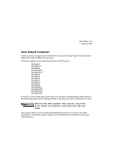
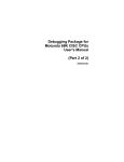
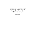
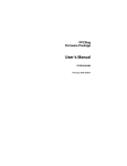
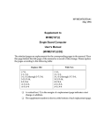
MVME197BUG/D1A1
August 1994
Supplement to
MVME197BUG
197Bug™ Debugging Package
User’s Manual
(MVME197BUG/D1)
The attached pages are replacements and/or additions to the user’s manual. They
correct minor errors and update some features.
Please replace the pages according to the following table and place this page behind
the title page of the user’s manual as a record of this change:
Replace Old
v/vi,
xvii/xviii,
1-3/1-4,
1-7/1-8,
1-11 through 1-14,
3-53 through 3-56,
3-63/3-64,
5-3/5-4,
5-73/5-74,
A-1 through A-4,
IN-5/IN-4,
IN-9/IN-10,
IN-13/IN-14
With New
v/vi,
xvii/xviii,
1-3/1-4,
1-7/1-8,
1-11 through 1-14,
3-53 through 3-56,
3-63/3-64,
5-3/5-4,
5-73/5-74,
A-1 through A-4,
IN-5/IN-4,
IN-9/IN-10,
IN-13/IN-14
❏
A vertical bar (|) in the margin of a replacement page indicates a text
change or addition.
❏
The supplement number is shown at the bottom of each replacement page.
Notice
While reasonable efforts have been made to assure the accuracy of this document,
Motorola, Inc. assumes no liability resulting from any omissions in this document, or
from the use of the information obtained therein. Motorola reserves the right to revise
this document and to make changes from time to time in the content hereof without
obligation of Motorola to notify any person of such revision or changes.
No part of this material may be reproduced or copied in any tangible medium, or
stored in a retrieval system, or transmitted in any form, or by any means, radio,
electronic, mechanical, photocopying, recording or facsimile, or otherwise, without the
prior written permission of Motorola, Inc.
Restricted Rights Legend
If the documentation contained herein is supplied, directly or indirectly, to the U.S.
Government, the following notice shall apply unless otherwise agreed to in writing by
Motorola, Inc.
Use, duplication, or disclosure by the Government is subject to restrictions as set forth
in subparagraph (c)(1)(ii) of the Rights in Technical Data and Computer Software
clause at DFARS 252.227-7013.
Motorola, Inc.
Computer Group
2900 South Diablo Way
Tempe, Arizona 85282-9602
The following conventions are used in this document:
bold
is used for user input that you type just as it appears. Bold is also used for
commands, options and arguments to commands, and names of programs,
directories, and files.
italic
is used for names of variables to which you assign values. Italic is also used for
comments in screen displays and examples.
courier
is used for system output (e.g., screen displays, reports), examples, and system
prompts.
<RETURN>
represents the carriage return key.
CTRL
represents the Control key. Execute control characters by pressing the CTRL
key and the letter simultaneously, e.g., CTRL-d.
MVME197BUG/D1A1
Related Documentation
The following publications are applicable to the MVME197 module series and may
provide additional helpful information. If not shipped with this product, they may be
purchased by contacting your Motorola sales office.
Document Title
MVME197LE Single Board Computer User’s Manual
Motorola
Publication Number
MVME197LE
MVME197LE Single Board Computer Support Information SIMVME197LE
MVME197DP and MVME197SP Single Board Computer
User’s Manual
MVME197
MVME197DP and MVME197SP Single Board Computer
Support Information
SIMVME197
MVME197LE, MVME197DP, and MVME197SP Single
Board Computers Programmer’s Reference Guide
MVME197PG
MVME197BUG 197Bug Diagnostic Firmware User’s
Manual
MVME197DIAG
MVME712M Transition Module and P2 Adapter Board
User’s Manual
MVME712M
MVME712-12, MVME712-13, MVME712A,
MVME712AM, and MVME712B Transition Module and
LCP2 Adapter Board User’s Manual
MVME712A
MC68040/MC68EC040/MC68CL040 Microprocessor
User’s Manual
M68040UM/AD
MC88110 Second Generation RISC Microprocessor User’s MC88110UM/AD
Manual
MC88410 Secondary Cache Controller User’s Manual
N otes
MC88410UM/AD
1. The support information manuals (SIMVME197LE and
SIMVME197) contain: the connector interconnect signal
information, parts lists, and the schematics for the
specific board indicated.
MVME197BUG/D1A1
List of Figures
FIGURES
Figure 1-1. Flow Diagram of 197Bug Start-Up for BOOT ROM.......................... 1-3
Figure 1-2. Flow Diagram of 197Bug Start-Up for FLASH-based
Debugger.................................................................................... 1-7
Figure 1-3. Flow Diagram of 197Bug Field Service Menu
Operational Mode ................................................................... 1-13
Figure 1-4. Network Boot Support Modules........................................................ 1-33
Figure A-1. Flow Diagram of 197Bug Field Service Menu
Operational Mode .................................................................... A-2
MVME197BUG/D1A1
xvii
xviii
MVME197BUG/D1A1
Start-Up Flow Diagrams
1
2
RESET
INITIALIZE MPU REGISTERS
SET PSR
CLEAR LINKER REGISTERS
CLEAR ASIC PROBE FLAG
CLEAR FPU STATUS
CLEAR CONFIDENCE TEST FLAG
ARE WE
THE MASTER
MPU?
YES
NO
CLEAR MASTER INDICATOR
(MPU REGISTER)
INITIALIZE BUSSWITCH ADDRESS
DECODERS
ENABLE ONBOARD I / O DEVICES
ENABLE ACCESS TO VMEBUS
SPIN UNTIL RELEASED BY MASTER MPU
GO TO FLASH
IS
FLASH
EMPTY?
NO
YES
SET MASTER INDICATOR (MPU REGISTER)
SET FLAG
SET UP BUSSWITCH SEMAPHORE IN
BUSSWITCH GPRS TO LOCK SLAVE MPU’S
EXTERNAL
CACHE OR
MULTIPLE
MPUS
RELEASE SLAVE MPU’S TO REQUEST BUS
NO
DELAY FOR SLAVE CHECK-IN
TO SEMAPHORE
YES
ENABLE EXTERNAL CONTROL
FUNCTIONS IN BUSSWITCH
DISABLE BOOT ROM DECODE AT ZERO
2
1
3
Figure 1-1. Flow Diagram of 197Bug Start-Up for BOOT ROM
(Sheet 1 of 4)
MVME197BUG/D1A1
1-3
1
1
197Bug General Information
3
4
DOUBLE
BUTTON
RESET?
YES
FUNCTIONAL
DEBUGGER
RAM FOUND?
NO
FLASH
EMPTY
FLAG SET?
YES
NO
JUMP TO FLASH FAIL LIGHT
YES
NO
CONFIGURE HARDWARE PER ROM
DEFAULT PARAMETERS
GO TO FLASH
(NOTE: NORMAL RESET PATH)
WAIT FOR ABORT BUTTON RELEASE
CLEAR BUSSWITCH ROM0 BIT TO
ENABLE DRAM DECODE
MEMORY TEST ON SPECIFIED
DEBUGGER WORK PAGE (64 KILOBYTES)
AS PER ROM PARAMETERS
(MEMORY SEARCH DIRECTIVES)
POWER-UP?
NO
YES
INVALIDATE MPU CACHES
CLEAR DEBUGGER WORK PAGE
SET POWER-UP INDICATOR
CLEAR WARM START FLAG
CONFIDENCE TEST
PENDING INTERRUPT CHECK
INITIALIZE DEBUGGER VARIABLES
(STACK, VECTOR TABLES, ETC.)
SET UP SINGLE MEMORY SUBSYSTEM
FIND AND TEST DEBUGGER
WORKSPACE RAM
INITIALIZE BOARD IDENTIFIER BLOCK
INITIALIZE EXCEPTION HANDLING
4
5
Figure 1-1. Flow Diagram of 197Bug Start-Up for BOOT ROM
(Sheet 2 of 4)
1-4
MVME197BUG/D1A1
Start-Up Flow Diagrams
1
RESET
INITIALIZE AS SLAVE MPU
INITIALIZE MPU REGISTERS
SET PSR
CLEAR LINKER REGISTERS
CLEAR ASIC PROBE FLAG
CLEAR FPU STATUS
CLEAR CONFIDENCE TEST FLAG
COMMAND
POINTER
SEMAPHORE
VALID?
INITIALIZE BUSSWITCH ADDRESS
DECODERS
ENABLE ONBOARD I / O DEVICES
ENABLE ACCESS TO VMEBUS
EXTERNAL
CACHE OR
MULTIPLE
MPUS?
2
NO
YES
EXECUTE COMMAND
NO
DOUBLE BUTTON
RESET?
NO
YES
YES
ENABLE EXTERNAL CONTROL
FUNCTIONS IN BUSSWITCH
ARE WE THE
MASTER MPU?
WAIT FOR ABORT BUTTON RELEASE
CLEAR BUSSWITCH ROM0 TO
ENABLE DRAM DECODE
YES
NO
INVALIDATE MPU CACHES
SPIN ON SEMAPHORE
UNTIL RELEASED BY MASTER
CONFIDENCE TEST
PENDING INTERRUPT CHECK
1
2
3
Figure 1-2. Flow Diagram of 197Bug Start-Up for FLASH-based Debugger
(Sheet 1 of 6)
MVME197BUG/D1A1
1-7
1
1
197Bug General Information
4
3
SET UP ALL RAM SUBSYSTEMS
ENABLE ONLY THE LARGEST DRAM
SUBSYSTEM AT ZERO
MOVE ALL OTHERS TO $80000000
TEMPORARILY
MAP AND ENABLE REMAINING MEMORY
SUBSYSTEMS
CONFIGURE ADDRESS DECODERS
MEMORY TEST ON SPECIFIED
DEBUGGER WORK PAGE (64 KILOBYTES)
AS PER NVRAM / ROM PARAMETERS
(MEMORY SEARCH DIRECTIVES)
FIND AND TEST DEBUGGER
WORK SPACE RAM
FUNCTIONAL
DEBUGGER
RAM FOUND?
YES
POWER-UP?
NO
NO
YES
JUMP TO FLASH FAIL LIGHT
CLEAR DEBUGGER WORK PAGE
SET POWER-UP INDICATOR
CLEAR WARM START FLAG
SET SYSFAIL NEGATE FLAG
DOUBLE BUTTON
RESET?
YES
NO
INITIALIZE DEBUGGER VARIABLES
(STACK, VECTOR TABLES, ETC.)
SET SYSFAIL NEGATE FLAG
CONFIGURE HARDWARE PER NVRAM
PARAMETERS
INITIALIZE BOARD IDENTIFIER BLOCK
INITIALIZE EXCEPTION HANDLING
CONFIGURE HARDWARE PER ROM
DEFAULT PARAMETERS
4
INITIALIZE CHARACTER I / O PORTS
CLEAR CHARACTER I / O BUFFERS
5
Figure 1-2. Flow Diagram of 197Bug Start-Up for FLASH-based Debugger
(Sheet 2 of 6)
1-8
MVME197BUG/D1A1
Start-Up Flow Diagrams
9
NO
10
ROM
BOOT ENABLED
AND ROM BOOT CODE
INSTALLED?
SYSTEM
MODE?
NO
YES
YES
HALT
WAIT 5 SECONDS
FOR ANY CHARACTER
TO HALT
GO TO TARGET STATE
EXECUTE ROM BOOT CODE
DISABLE AUTOBOOT CHECKS
NO HALT
AUTO BOOT
ENABLED?
EXECUTE SELFTEST
NO
YES
ST
FAILURE?
NO
YES
ATTEMPT AUTO BOOT
DISABLE AUTOBOOT CHECKS
IF AUTO BOOT
LOAD OKAY?
SYSFAIL NEGATE
FLAG TRUE?
NO
NO
YES
YES
GO TO TARGET STATE
EXECUTE AUTO BOOT CODE
NEGATE SYSFAIL
AUTO
BOOT CHECKS
DISABLED?
NETWORK BOOT
ENABLED?
NO
10
NO
YES
YES
GO TO MAIN (MONITOR)
GO TO MAIN (MONITOR)
Figure 1-2. Flow Diagram of 197Bug Start-Up for FLASH-based Debugger
(Sheet 5 of 6)
MVME197BUG/D1A1
1-11
1
1
197Bug General Information
MAIN
FIELD
SERVICE MENU
ENABLED?
YES
GO TO FIELD SERVICE MENU
NO
DISPLAY DEBUGGER PROMPT
NO
INPUT?
YES
GO TO MAIN
TARGET CODE
EXECUTION?
YES
NO
EXECUTE COMMAND
RESTORE TARGET STATE
EXECUTE TARGET CODE
EXCEPTION
SAVE TARGET STATE
DISPLAY TARGET REGISTERS
GO TO MAIN
Figure 1-2. Flow Diagram of 197Bug Start-Up for FLASH-based Debugger
(Sheet 6 of 6)
1-12
MVME197BUG/D1A1
Start-Up Flow Diagrams
FIELD
SERVICE
MENU
DISPLAY SERVICE
MENU
CONTINUE SYSTEM
START-UP
DISPLAY SYSTEM
TEST ERRORS
SELECT ALTERNATE
BOOT DEVICE
DUMP MEMORY
TO TAPE
GO TO SYSTEM
DEBUGGER
START CONVERSATION
MODE
INITIATE A SERVICE
CALL
EXIT CONCURRENT
MODE
ERROR
EXTENSIVE
SYSTEM SELF TEST
NO ERRORS
ERROR
AUTO BOOT
FROM SPECIFIED
DEVICE
NO ERRORS
GO TO TARGET STATE
EXECUTE “BOOTED” CODE
Figure 1-3. Flow Diagram of 197Bug Field Service Menu Operational Mode
MVME197BUG/D1A1
1-13
1
1
197Bug General Information
Comparison with M68000-Based Firmware
Those users who have used one or more of Motorola's other debugging
packages will find 197Bug very similar, after making due allowances for the
architectural differences between the M68000 and M88000 CPU architectures.
These are primarily reflected in the instruction mnemonics and addressing
modes of the assembler/disassembler, and in the use of registers instead of the
stack for the passing of arguments to or from the TRAP #496 handler. Some
effort has also been made to make the interactive commands more consistent.
For example, delimiters between commands and arguments may now be
commas or spaces interchangeably.
197Bug Implementation
FLASH-Based Debugger
197Bug is contained in the FLASH memory devices located on the MVME197
board. The FLASH devices are electrically re-writable and may be
reprogrammed without removing the physical devices from the MVME197
board. This allows the user to incorporate updated versions of the 197Bug as
they become available by simply loading the newer version into the FLASH
memory and overwriting the older version.
The PFLASH command (refer to the 197Bug Debugger Command Set chapter)
describes how to reprogram the FLASH memory contents. The executable
code is checksummed at every power-on or reset firmware entry. Users are
cautioned against reprogramming of the FLASH memory contents unless
rechecksum precautions are taken. Refer to the CS command description in
the 197Bug Debugger Command Set chapter for checksum information.
!
WARNING
Reprogramming any portion of FLASH memory will erase
everything currently contained in FLASH, including the
debugger. A valid version of 197Bug must be transferred
from RAM into the FLASH during FLASH reprogramming
in order for the debugger to operate.
The 197Bug Debugger Command Set chapter describes the
command set of the FLASH-based debugger.
BOOT ROM
A subset of 197Bug is also programmed into the BOOT ROM, which is an
EPROM or One-Time Programmable ROM on the MVME197 module. This
scaled-down 197Bug is referred to as the “BootBug”, or “197BBug”.
1-14
MVME197BUG/D1A1
Set Environment to Bug/Operating System
Set Environment to Bug/Operating System
ENV
ENV [;[D]]
The ENV command allows the user to interactively view/configure all Bug
operational parameters that are kept in Battery Backup RAM (BBRAM), also
known as Non-Volatile RAM (NVRAM). The operational parameters are
saved in NVRAM and used whenever power is lost.
Any time the Bug uses a parameter from NVRAM, the NVRAM contents are
first tested by checksum to ensure the integrity of the NVRAM contents. In the
instance of BBRAM checksum failure, certain default values are assumed as
stated in the examples below.
The bug operational parameters (which are kept in NVRAM) are not
initialized automatically on power up/warm reset. It is up to the Bug user to
invoke the ENV command. Once the ENV command is invoked and executed
without error, Bug default and/or user parameters are loaded into NVRAM
along with checksum data. If any of the operational parameters have been
modified, these new parameters will not be in effect until a reset/powerup
condition.
If the ENV command is invoked with no options on the command line, the user
is prompted to configure all operational parameters. If the ENV command is
invoked with the option D, ROM defaults will be loaded into NVRAM.
Programming the VMEbus to Local Peripheral Bus Map Decoders
The VMEbus slave map decoders allow a VMEbus master to view a block of
the local peripheral bus (usually memory) through a VMEbus window. The
following procedure can be used with the ENV command to configure the
VMEbus to Local Peripheral Bus (slave) map decoders. This is not the only
procedure that can be used to program the map decoders.
1.
Determine the local base address (for onboard DRAM memory this is the
Base Address of Local Memory) and size of the memory block to be
viewed through the VMEbus window. The following restrictions must be
considered when defining the local peripheral bus address of the block
and the block size.
The map decoder logic performs address translation by replacing a
portion of the VMEbus address with an address from the address
translation register. Therefore, translation is performed in increments of
the block size and the block size must be a power of 2 and located on a
power of 2 boundary. For example, a 32MB block cannot be addressed on
MVME197BUG/D1A1
3-53
3
197Bug Debugger Command Set
ENV
a 4MB boundary. However, any 4MB block of the 32MB memory can be
addressed on any 4MB boundary.
3
Also note that if the block size is not a power of 2, then rounding up to a
power of 2 boundary is necessary. For example, a 12MB block must be
accessed at 0, 16MB, 32MB, etc.
2.
Set the Slave Address Translation Address Register parameter with the
LOCAL base address of the block.
3.
Set the Slave Address Translation Select Register parameter with the 2's
compliment of the block size.
4.
Set the Slave Starting Address Register parameter with the starting
address of the VMEbus window.
5.
Set the Slave Ending Address Register parameter with the ending address
of the VMEbus window.
N ote
The VMEbus window size may be any number of 64KB
blocks up to the block size.
6.
If the VMEbus window is entirely below the 16MB boundary, enable A24
and/or A32 addressing. If the VMEbus window is entirely above the
16MB boundary, enable only A32 addressing. If the VMEbus window
spans the 16MB boundary, enable A32 addressing. If access is required to
the portion below the 16MB boundary using A24 addressing, the second
map decoder should be programmed to provide A24 access to the portion
of the VMEbus window below the 16MB boundary.
Set the Slave Control parameter to $01EF to enable A32 addressing, $01DF
to enable A24 addressing, and $01FF to enable A32 and A24 addressing.
Configuring ENV Parameters
The parameters to be configured are:
Bug or System environment [B/S] = S?
3-54
B
Disables automatic execution of extended confidence testing (ST)
on any reset and selects the 197-Bug> prompt in the debugger
command line mode. The SD command must be issued to allow
diagnostic execution.
S
Enables automatic execution of extended confidence testing (ST)
on any reset. Also, selects the 197-Diag> prompt, enabling
diagnostic test execution from the debugger command line.
MVME197BUG/D1A1
Set Environment to Bug/Operating System
ENV
Field Service Menu Enable [Y/N] = Y?
Y
N
Field service menu mode is selected. The menu operation is
explained in Appendix A. (Default)
Debugger command line mode is selected. The 197-Bug or 197Diag prompt will be displayed based on the Bug or System
environment parameter.
Remote Start Method Switch [G/M/B/N] = B?
The Remote Start Method Switch is used when the MVME197 is crossloaded from another VME-based CPU, to start execution of the crossloaded program.
G
M
B
N
Use the Global Control and Status Register (GCSR) in the
VMEchip2 to pass and start execution of cross-loaded program.
Use the Multiprocessor Control Register (MPCR) in shared RAM
to pass and start execution of cross-loaded program.
Use both the GCSR and the MPCR methods to pass and start
execution of cross-loaded program. (Default)
Do not use any Remote Start Method.
Probe System for Supported Disk/Tape Controllers [Y/N] = Y?
Y
N
Accesses will be made to the VMEbus to determine the presence
of supported controllers. (Default)
Accesses will not be made to the VMEbus to determine the
presence of supported controllers.
Negate VMEbus SYSFAIL* Always [Y/N] = N?
Y
N
Negate VMEbus SYSFAIL during board initialization.
Negate VMEbus SYSFAIL after successful completion or entrance
into the bug command monitor. (Default)
Local SCSI Bus Reset on Debugger Setup [Y/N] = Y?
Y
N
Local SCSI bus is reset on debugger setup.
Local SCSI bus is not reset on debugger setup.
Local SCSI Bus Negotiations Type [A/S/N] = A?
A
S
N
MVME197BUG/D1A1
Use Asynchronous negotiations on the Local SCSI bus.
Use Synchronous negotiations on the Local SCSI bus.
(None). Do not precede the SCSI data transfer with a type
negotiation. Do all data transfers in Asynchronous mode.
3-55
3
197Bug Debugger Command Set
ENV
Ignore CFGA Block on a Hard Disk Boot [Y/N] = Y?
Y
3
N
Enable the ignorance of the Configuration Area (CFGA) Block
(hard disk only).
Do not enable the ignorance of the Configuration Area (CFGA)
Block.
Auto Boot Enable [Y/N] = N?
Y
N
The auto boot function is enabled.
The auto boot function is disabled. (Default)
Auto Boot at power-up only [Y/N] = Y?
Y
N
Auto Boot is attempted at power up reset only. (Default)
Auto Boot is attempted at any reset.
Auto Boot Controller LUN = 00?
Refer to Appendix E for a listing of disk/tape controller modules currently
supported by the Bug. The default for this parameter is $0.
Auto Boot Device LUN = 00?
Refer to Appendix E for a listing of disk/tape devices currently supported
by the Bug. The default for this parameter is $0.
Auto Boot Abort Delay = 15?
Time in seconds that the Auto Boot sequence will delay before starting the
boot. The purpose is to allow the user the option of stopping the boot by
use of the Break key. The time value is from 0 through 255 seconds.
Auto Boot Default String [NULL for an empty string] = <none>
The user may specify a string (filename) which is passed on to the code
being booted. The maximum length of this string is 16 characters. The
default for this parameter is the null string.
ROM Boot Enable [Y/N] = N?
Y
N
The ROMboot function is enabled.
The ROMboot function is disabled. (Default)
ROM Boot at power-up only [Y/N] = Y?
3-56
Y
ROMboot is attempted at power up only. (Default)
N
ROMboot is attempted at any reset.
MVME197BUG/D1A1
Set Environment to Bug/Operating System
ENV
Master Address Translation Select #4 = 00000000?
This register defines which bits of the address are significant. A logical one
“1” indicates significant address bits, logical zero “0” is non-significant.
(Default is 0).
Master Control #4 = 00?
This defines the access characteristics for the address space defined with
this master address decoder. The default is $00.
Short I/O (VMEbus A16) Enable [Y/N] = Y?
Y
N
Yes, Enable the Short I/O Address Decoder. (Default)
Do not enable the Master Address Decoder.
Short I/O (VMEbus A16) Control = 01?
This defines the access characteristics for the address space defined with
the Short I/O address decoder. The default is $01.
F-Page (VMEbus A24) Enable [Y/N] = Y?
Y
N
Yes, Enable the F-Page Address Decoder. (Default)
Do not enable the F-Page Address Decoder.
F-Page (VMEbus A24) Control = 02?
This defines the access characteristics for the address space defined with
the F-Page address decoder. The default is $02.
ROM Speed Bank A Code = 03?
ROM Speed Bank B Code = 03?
These parameters are used to set up the ROM speed, which is dependent
on the MPU clock speed.
MPUCLK
ROM Speed A and B (Default values)
50
40
33
any other
3
2
2
7
PCC2 Vector Base = 05?
VMEC2 Vector Base #1 = 06?
VMEC2 Vector Base #2 = 07?
These parameters are the base interrupt vector for the component
specified. (Default: PCCchip2 = $05, VMEchip2 Vector 1 = $06, VMEchip2
Vector 2 = $07).
MVME197BUG/D1A1
3-63
3
197Bug Debugger Command Set
ENV
VMEC2 GCSR Group Base Address = D0?
This parameter specifies the group address ($FFFFXX00) in Short I/O for
this board. (Default = $D0).
3
VMEC2 GCSR Board Base Address = 00?
This parameter specifies the base address ($FFFFCEXX) in Short I/O for
this board. (Default = $00).
VMEbus Global Time Out Code = 01?
This controls the VMEbus timeout when systems controller. (Default $01 =
64 microseconds).
Local Peripheral Bus Time Out Code = 01?
This controls the local peripheral bus timeout. (Default $00 =64
microseconds).
VMEbus Access Time Out Code = 02?
This controls the local peripheral bus to VMEbus access timeout. (Default
$02 = 32 milliseconds).
3-64
MVME197BUG/D1A1
System Call Routines
Table 5-1. 197Bug System Call Routines (Continued)
Code
Function
Description
$0024
.WRITELN
Output line (pointer/count format)
$0025
.WRITDLN
Output line with data (pointer/count format)
$0026
.PCRLF
Output carriage return and line feed
$0027
.ERASLN
Erase line
$0028
.WRITD
Output string with data (pointer/count format)
$0029
.SNDBRK
Send break
$0043
.DELAY
Timer delay function
$0050
.RTC_TM
Time initialization for RTC
$0051
.RTC_DT
Date initialization for RTC
$0052
.RTC_DSP
Display RTC time and date
$0053
.RTC_RD
Read the RTC Registers
$0060
.REDIR
Redirect I/O of a TRAP #496 function
$0061
.REDIR_I
Redirect input
$0062
.REDIR_O
Redirect output
$0063
.RETURN
Return to 197Bug
$0064
.BINDEC
Convert binary to Binary Coded Decimal (BCD)
$0067
.CHANGEV
Parse value
$0068
.STRCMP
Compare two strings (pointer/count format)
$0069
.MULU32
Multiply two 32-bit unsigned integers
$006A
.DIVU32
Divide two 32-bit unsigned integers
$006B
.CHK_SUM
Generate checksum
$0070
.BRD_ID
Return pointer to board ID packet
$0071
.ENVIRON
Access boot environment parameters
$0073
.PFLASH
Program FLASH Memory
$0090
.SIOPEPS
Retrieve SCSI pointers (NOTE 3)
$0100
.FORKMPU
Fork MPU (Multiple MPU Configuration) (NOTE 2)
$0101
.FORKMPUR
Fork Idle MPU with Register Set (NOTE 2)
MVME197BUG/D1A1
5
5-3
System Calls
Table 5-1. 197Bug System Call Routines (Continued)
Code
5
Function
Description
$0110
.IDLEMPU
Idle MPU (Multiple MPU Configuration) (NOTE 2)
$0120
.IOINQ
Port Inquiry
$0124
.IOINFORM
Port Inform
$0128
.IOCONFIG
Port Configure
$012C
.IODELETE
Port Delete
$0130
.SYMBOLTA
Attach Symbol Table
$0131
.SYMBOLTD
Detach Symbol Table
$0140
.ACFSTAT
ACFAIL Status Inquiry
N otes
1. In most examples of commands and displays given in
this manual, 197Bug is used. However, the commands,
displays, and system calls apply to all 88K RISC
debugging packages, unless otherwise noted.
2. This utility is only available on multi-processor
modules such as the MVME197 series and the
MVME188 series.
3. This function applies only to modules with SCSI; does
not apply to MVME188 or MVME188A series modules.
5-4
MVME197BUG/D1A1
.PCRLF Function
.PCRLF
TRAP FUNCTION: .PCRLF - Print <CR><LF> sequence
CODE:
$0026
DESCRIPTION:
.PCRLF sends a <CR><LF> sequence to the default
output port.
ENTRY CONDITIONS:
5
No arguments required.
EXIT CONDITIONS DIFFERENT FROM ENTRY:
None
MVME197BUG/D1A1
5-73
System Calls
.PFLASH Function
.PFLASH
TRAP FUNCTION: .PFLASH - Program FLASH memory
CODE:
$0073
DESCRIPTION:
The purpose of this TRAP is to program FLASH memory
under program control. The address of the packet is
passed as an argument to the function. The address of the
packet is passed in the longword memory location
pointed to by the current stack pointer. The packet
contains the necessary arguments/data to program the
FLASH memory.
5
ENTRY CONDITIONS:
SP ==>
Address:
Starting address of control packet longword
EXIT CONDITIONS DIFFERENT FROM ENTRY:
None
FORMAT OF FLASH MEMORY CONTROL PACKET:
The FLASH Memory Control Packet must be longword/word (32-bit)
aligned.
31
$00
24
23
16
15
5
Status Word
8
7
0
Control Word
$04
Source Starting Address
$08
Number of Bytes to Program
$0C
Destination Starting Address
$10
Instruction Execution Address
Field descriptions:
Control/Status Word
Specifies control and status of the various phases of the FLASH memory
programming. This parameter has two 16-bit parts: bits #31 to #16 specify
status and bits #15 to #0 specify control.
5-74
MVME197BUG/D1A1
MVME197BUG SYSTEM
MODE OPERATION
A
General Description
To provide compatibility with the Motorola Delta Series systems, the
MVME197Bug has a special mode of operation for system environments.
If system mode is selected in the ENV parameters (default), extended
confidence tests are run automatically at power-up or at any reset of the
MVME197. A delay precedes this testing and the tests can be skipped by
typing “S” on the console keyboard. During this delay, control will be passed
to the debugger prompt or menu (see below) if errors are detected.
If the field service menu is enabled, a menu will be displayed instead of the
debugger prompt, if none of the alternate actions (AB, RB, NBO, etc.) has been
enabled via the ENV parameters. This allows several system start-up features
to be selected, such as:
1.
Continue System Start-Up
2.
Select Alternate Boot Device
3.
Go to System Debugger
4.
Initiate Service Call
5.
Display System Test Errors
6.
Dump Memory to Tape
The flow of menu mode operation is shown in Figure A-1. Upon either power
up or system reset, the MVME197 first executes a limited confidence test suite.
This is the same test suite that the Bug normally executes on power up when
not in the system mode. Upon successful completion of the limited confidence
tests, a five second period is allowed to interrupt the start-up sequence. By
typing any character the user can cause the module to deviate from the normal
start-up sequence and display one of the debugger prompts or display the
field service menu, permitting the selection of an alternate boot device, entry
to the debugger, etc., as described above. Upon selection of “continue startup” the module conducts a more extensive confidence test (ST). Successful
completion of the extended confidence test initiates the autoboot sequence,
with boot taking place either from the default device (refer to the 197Bug
Debugger Command Set chapter for information on entering/changing the
default boot device) or from the selected boot device if an alternate device has
been selected.
MVME197BUG/D1A1
A-1
A
MVME197Bug System Mode Operation
If the limited confidence test fails to complete correctly, the FAIL LED may
blink to indicate a failure and processing is suspended.
FIELD
SERVICE
MENU
DISPLAY SERVICE
MENU
CONTINUE SYSTEM
START-UP
DISPLAY SYSTEM
TEST ERRORS
SELECT ALTERNATE
BOOT DEVICE
DUMP MEMORY
TO TAPE
GO TO SYSTEM
DEBUGGER
START CONVERSATION
MODE
INITIATE A SERVICE
CALL
EXIT CONCURRENT
MODE
ERROR
EXTENSIVE
SYSTEM SELF TEST
NO ERRORS
ERROR
AUTO BOOT
FROM SPECIFIED
DEVICE
NO ERRORS
GO TO TARGET STATE
EXECUTE “BOOTED” CODE
Figure A-1. Flow Diagram of 197Bug Field Service Menu Operational Mode
A-2
MVME197BUG/D1A1
Menu Details
Error message explanations for the extended confidence test are given in the
heading for the failed test.
Menu Details
Following are more detailed descriptions of the menu selections.
Continue System Start Up
The only action required by the user is to enter a 1 followed by a carriage
return. The system then continues the start-up process by performing
extended confidence testing (ST) followed by a system boot from the device
specified by the ENV parameters active.
Select Alternate Boot Device
After entering a 2, the user is prompted with:
Enter Alternate Boot Device:
Controller:
Drive
:
File
:.
The selection of devices supported by the 197Bug is listed in Appendix E.
Entry of a selected device followed by a carriage return redisplays the menu
for another selection, normally “continue system start-up” at this point.
Go to System Debugger
When 3 is selected, this entry places the user in 197Bug diagnostic mode, if
system mode is selected, indicated by the prompt 197-Diag>. If desired, return
to the menu can be accomplished by typing “menu” when the Bug prompt
appears. If not in system mode, the 197-Bug> prompt will be displayed and the
user must type “SD” to enable diagnostic execution. When in 197-Diag mode,
operation is defined by the MVME197BUG 197Bug Diagnostic Firmware User’s
Guide.
Initiate Service Call
The initiate service call function (enter 4) is described in the following sections.
General Flow
Initiated by typing a 4 <CR> in response to the menu prompt, this function
is normally used to complete a connection to a service organization which
can then use the “dual console” mode of operation to assist a customer with
a problem. Interaction with the service call function proceeds as follows:
MVME197BUG/D1A1
A-3
A
A
MVME197Bug System Mode Operation
First, the system asks:
Modem Type:
0) Terminal
1) Manual
2) UDS-2122662
3) UDS-2122980 (Hayes)
4) UDS-2123382 (Hayes)
Your Selection ( )?.
Explanation:
UDS means that the modem is compatible with the UDS modem protocol
as used in internal Delta Series modems. The model number of this
modem is UDS 2122662.
Hayes means that the modem is compatible with a minimal subset of the
Hayes modem protocol. This minimum subset is chosen to address the
broadest spectrum of Hayes compatible modem products. Note that the
modem itself is not tested when Hayes protocol is chosen, while the
modem is tested with the UDS protocol choice.
Manual mode connects directly to the modem in an ASCII terminal mode,
allowing any nonstandard protocol modem to be used.
Terminal mode is used to connect any ASCII terminal in place of a modem,
via a null modem, or equivalent cable. It is useful in certain troubleshooting applications for providing a slave terminal without the necessity
of dialing through a modem.
When a selection of one of the above options is made (option 0 in this case),
the system asks:
Do you want to change the baud rate from 1200 (Y/N)?
Note that any question requiring a Y or N answer defaults to the response
listed furthest to the right in the line (i.e., a question with Y/N defaults to
NO if only a carriage return is entered. If the user answers Y to the baud
rate question, the system prompts:
Baud rate [300, 1200, 2400, 4800, 9600] 1200?
A-4
MVME197BUG/D1A1
Define Constant Directive 4-2
define macros 3-106
delay, timer 5-14
delete breakpoint 3-22
delete I/O port 5-46
delete macros 3-106
delimiter 2-2
Delta Series A-1
description of 197Bug 1-1
detach port 3-154
detach printer 3-149
detach symbol table 3-182, 5-91
detach/format port 3-150
Device Descriptor Packet 5-16
Device Descriptor Table 1-29, 3-84, 3-91
Device LUN (DLUN) 3-13, 3-19, 3-86,
3-92, 3-112, 3-127, 3-128, 3-144,
5-17
device LUN (DLUN) 3-82
device name 3-161
device parameters, default 1-32
device probe 3-84
device probe function 1-29
DI option 3-114, 3-117, 4-7
diagnostic directory 1-37, 3-176
diagnostic facilities 1-37
diagnostic mode A-3
diagnostic prompt 1-2, B-2
diagnostic, memory map 3-121
diagnostics 3-170
direct access device E-2, E-3
Directives 4-1
directory 3-176
directory, switch 3-176
disable ROMboot 3-159
Disassembled Source Line 4-3
disassembler 4-3
disassembler, one-line 3-48
disk access, physical 3-86
disk configuration 3-91
disk control 5-20
disk controller default configuration E-2
MVME197BUG/D1A1
disk I/O control 3-82
disk I/O error codes 1-32
disk I/O support 1-29
disk I/O via 197Bug commands 1-30
Disk I/O via 197Bug System Calls 1-31
disk IOT command parameters E-5
Disk type D-3
disk, configure 5-16
disk, format 5-22
disk, read/write 5-24
Disk/Tape Controller Default
Configurations E-2
Disk/Tape Controller Modules
Supported E-1
display macros 3-106
display memory 3-114
display offset registers 3-146
display registers 3-161
display symbol table 3-185
Display System Test Errors A-10
display time 5-82
Display Time and Date 3-190
divide integers 5-15
DLUN E-2, E-3, E-4, G-1
DMA Block of Memory Move 3-43
DMA command 3-43
Double Precision 3-114, 3-117, 3-172,
3-173
double precision real 2-8
Double-Button Reset 1-25
drive characteristics D-5
Drive data density D-3
Drive track density D-3
DS command 3-48, 4-7
DU command 3-49
Dump Memory to Tape A-10
Dump S-Records 3-49
dump utilities C-3
E
ECC 5-18
ECC data burst length D-2
IN-5
I
N
D
E
X
Index
I
N
D
E
X
ECHO command 3-51
Echo String 3-51
edit macros 3-109
EIA-232-D port connectors 1-18, 2-6
Embedded servo drive D-3
enable ROMboot 3-159
Enable/Disable Macro Expansion
Listing 3-111
encoding C-2
end of tape (EOT) 3-88
Enhanced small device interface (ESDI)
5-10
Entering a Source Line 4-8
entering and debugging programs 2-5
Entering and Modifying Source
Programs 4-7
Entering Branch Operands 4-8
entering debugger command lines 2-1
ENV command 3-53
Environment (ENV) command 1-20, 1-22
environment parameters, read/write 5-27
environment, configuring 3-54
environment, preserving 2-6
environment, set 3-53
EOT 5-23
EPROMs 3-159
erase line 5-30
error codes, disk I/O 1-32
error codes, network I/O 1-35
error correction code (ECC) 3-95
Error Handling Codes F-12
errors, system test A-10
escape character 3-191
ESDI Winchester hard drive E-2
Ethernet G-1
Ethernet driver 1-34
Ethernet interface 1-32
exception handler 5-12
exception handler semaphore 3-175
exception vectors used by 197Bug 2-6
EXEC command 1-17
executable instruction 4-2
IN-6
execute debugger 3-174
execute one line 3-185
execute user program 3-71
expansion of macros 3-111
exponent field 2-7
expression 2-2
expression as a parameter 2-2
Extended attributes mask D-2
Extended attributes word D-2
Extended confidence tests A-1
Extended parameters mask D-2
F
F option, IOT 3-91
field service menu A-1
file blocks, retrieve 5-66
file number 5-25, A-11
File Zero Structure A-10
file, open for read 5-64
filemark 3-88, 5-25
fill block of memory 3-10
fixed-length buffer 5-77
flag byte 3-87, 5-25
FLASH-Based Debugger 1-14
flexible diskette E-2, E-3
floating point data 3-172, 3-173
floating point instructions 2-7
floating point SFU 2-8
floating point support 2-7
floppy disk command parameters E-5
Floppy disk format D-3
Floppy disk size D-3
floppy drive E-2, E-3
FORK command 3-65
fork idle MPU 5-32
Fork Idle MPU at Address 3-65
Fork Idle MPU with Registers 3-66
fork MPU 5-31
FORKWR command 3-66
format 4-2
format disk 5-22
format/detach port 3-150
MVME197BUG/D1A1
local floppy drive E-3
local peripheral bus map decoders 3-53
logical block 1-29
Logical Unit Number (LUN) 1-30, 3-13,
3-86
longword F-10
loop, read 3-171
loop, write 3-23, 3-199
LUN 3-91
M
M 3-117
M= B-3
M68000 F-10
M88000 F-10
M88000 firmware 1-1
MA command 3-106
Machine-Instruction Operation Codes
4-1
Macro Define/Display/Delete 3-106
macro definitions 3-106, 3-109
macro definitions prompt B-3
Macro Edit 3-109
macros, edit 3-109
macros, expansion 3-111
macros, save/load 3-112
MACSI/Controller Error Codes F-11
MAE command 3-109
Main Processor Registers 4-4
MAL command 3-111
mantissa field 2-7
Manual mode A-4
Manual Mode Connection A-8
MAR command 3-112
mask, interrupt request 3-101
MAW command 3-112
MC88110 Assembly Language 4-1
MC88110 CMP instruction 5-88
MC88110 conditional TRAP instructions
5-1
MC88110 exception vectors 2-6
MC88110 instruction set 4-3
MVME197BUG/D1A1
MC88110 machine language 4-1
MC88110 Second Generation RISC
Microprocessor User's Manual 2-8
MC88110 TRAP instructions 2-6
MD command 3-114
media characteristics D-5
Memory Address 3-87
memory compare, block 3-8
Memory Display 3-114
memory fill, block 3-10
memory initialize, block 3-15
memory location D-1
Memory Map Diagnostic 3-121
Memory Modify 3-117
memory move, block 3-16
memory move, DMA block 3-43
memory requirements 1-27
memory search, block 3-28
Memory Set 3-123
memory verify, block 3-31
Memory Write 3-124
memory, dump to tape A-10
menu A-1
MENU command 3-116
Menu Details A-3
menu mode operation A-1
menu, help 3-76
Message Command A-6
meta symbols 2-2
MK48T08 5-83, 5-85
MM command 3-117
MMD command 3-121
mnemonics 4-1
Mnemonics and Delimiters 4-3
mode sense 1-29
mode, concurrent 3-33
mode, no concurrent 3-35
modem connection, manual A-8
modem functions 3-168
Modem ID 5-49
modify memory 3-117
modify offset registers 3-146
IN-9
I
N
D
E
X
Index
I
N
D
E
X
modify registers 3-172
Modulus 4-5
Mono 5-51
move block of memory 3-16
move DMA block of memory 3-43
MPU 5-32
MPU Clock Speed Calculation 1-27
MPU Execution/Status 3-174
MPU registers 3-162
MPU with registers, idle, fork at address
3-66
MPU, fork Idle 5-32
MPU, fork multiple 5-31
MPU, idle multiple 5-41
MPU, idle, fork at address 3-65
MS command 3-123
multiply integers 5-53
Multiprocessor
Address
Register
(MPAR) 1-36
Multiprocessor Control Register (MPCR)
method 1-35
multiprocessor support 1-35
MVME197 SCSI Firmware Status Codes
F-2
MVME197BUG 1-1
MVME320 E-2
MVME320 Controller-Dependent Status
Codes F-4
MVME323 E-2
MVME323 Controller-Dependent Status
Codes F-5
MVME327A E-3
MVME327A Controller-Dependent
Status Codes F-7
MVME328 E-3
MVME328 Controller-Dependent Status
Codes F-11
MVME350 E-4
MVME350 Controller-Dependent Status
Codes F-13
MVME374 (AMD AM7990 - LANCE)
H-2, H-3
IN-10
MVME376 G-1
MW command 3-124
N
N option 3-28, 3-117
NAB command 3-126
NBH command 3-127
NBO command 3-128
negation, SYSFAIL* 1-26
network boot control module 1-35
Network Boot Operating System 3-128
Network Boot Operating System and
Halt 3-127
network boot support modules 1-33
network boot, automatic 3-126
network control functions 5-61
network controllers supported G-1
network file open 5-64
network file retrieve 5-66
network header file I-1
Network I/O Control 3-132
network I/O error codes 1-35
Network I/O Physical 3-137
network I/O support 1-32
Network I/O Teach (Configuration)
3-139
network parameters, configure 5-54
Network Ping 3-144
network read/write 5-68
next instruction, go to 3-69
NIOC command 3-132
NIOP command 3-137
NIOT command 3-139
no autoboot 3-6
No Concurrent Mode 3-35
NOAB command 3-6
NOBR command 3-22
NOCM command 3-35
NOMA command 3-106
NOMAL command 3-111
Non- Volatile RAM (NVRAM) 3-53
NOPA command 3-149
MVME197BUG/D1A1
ROMboot function 3-159
RS command 3-173
RTC, storage 3-158
RUN command 3-174
S
S option 3-114, 3-117, 3-172, 3-173, 3-183
sample ROMboot routine 1-22
sanity check 3-180
Save/Load Macros 3-112
Scatter/Gather Errors F-12
scientific notation 2-8
SCSI Bus Status F-2
SCSI Command F-1
SCSI Common Command Set (CCS) E-2,
E-3
SCSI Errors F-12
SCSI pointers, retrieve 5-86
SCSI status codes F-2
SD command 3-176
search block of memory 3-28
search symbol table 3-185
sector 1-29
sector size D-1
sectors versus blocks 1-29
Sectors/track D-1
Select Alternate Boot Device A-3
self-test 3-170
send break 5-87
send to host 5-68
Sense Key F-1
separating characters 4-4
Sequential access device E-2, E-3
SERIAL PORT 1 2-5
SERIAL PORT 2 2-5
serial port status, input 5-44
Server IP Address 3-127, 3-128
service call, initiate A-3
Set Environment to Bug/Operating
System 3-53
set memory 3-123
set registers 3-173
MVME197BUG/D1A1
Set Time and DateSET command 3-177
SETUP command 1-17
Setup System Parameters SETUP 1-17
sign field 2-7
signed hexadecimal 4-3
Single Board Computers E-2
Single Precision 3-114, 3-117, 3-172, 3-173
single precision real 2-8
single quotes 4-6
SIOP Status F-3
slave map decoders 3-53
Small Computer System Interface (SCSI)
5-9
source code 4-7
source line 2-5, 4-1
Source Line Format 4-3
source program 4-1
Source Program Coding 4-2
Spare sectors count D-2
Special Function Unit (SFU) 2-7
Spiral offset D-1
square brackets 2-2
S-record content C-1
S-record example C-3
S-record types C-2
S-record, creating C-3
S-records 3-102
S-records, display 3-49
S-records, verify 3-194
Starting head number D-1
start-up 1-18
startup, continue A-3
static variable space 1-27
static variables 3-169
status codes, controller-dependent F-4,
F-5, F-7, F-11, F-13, H-2
status codes, SCSI F-2
status inquiry 5-5
status of MPU 3-174
status packet 5-5
status word F-1, H-1
IN-13
I
N
D
E
X
Index
I
N
D
E
X
Stepping rate code D-2
stop bits 5-51
String 3-127, 3-128
String Formats for I/O 5-1
String literals 4-5
string literals 2-3
string pool 3-106
string, echo 3-51
string, output 5-72, 5-92, 5-94
string, read 5-78
strings, compare 5-88
supervisor address space 2-4
Switch Directories 3-176
Switch Directories (SD) command 1-2
SYM command 3-179
symbol base address 5-89
symbol table 3-179, 3-182, 3-183
Symbol Table Attach 3-179
Symbol Table Detach 3-182
Symbol Table Display/Search 3-185
symbol table, attach 5-89
symbol table, detach 5-91
SYMS command 3-185
synchronous data link control (SDLC)
5-51
syntactic variables 2-2
syntax 4-2
SYSCALL 4-1
SYSCALL System Call Directive 4-6
SYSFAIL* assertion/negation 1-26
System Call Directive 4-2
System Call Routines 5-2
system calls 5-1
system calls, disk I/O 1-31
System Console 1-18, 5-49
system console terminal 3-33
system controller 3-169
System Fail (SYSFAIL*) 1-20
System ID Number A-5
System Menu 3-116, 3-170
System Mode 1-19, 3-116, 3-168, A-12
system test errors, display A-10
IN-14
T
T command 3-185
T option 3-103
T option, IOT 3-92
TA command 3-188
tape controller default configuration E-2
tape dump A-10
Tape Dump File Map Entries A-10
Tape Dump Utility A-10
target IP 3-161, 3-185, 3-192
target register 3-173
temporary breakpoint 3-69, 3-74, 3-192
Terminal Attach 3-188
terminal input/output control 1-27
terminal mode A-4
Terminal Mode Operation A-10
terminal screen 3-194
termination record C-2
TFTP Protocol Module 1-34
TIME command 3-190
time, display 3-190, 5-82
time, initialize 5-85
time, set 3-177
time-of-day clock 3-177, 3-190
timer delay 5-14
TM command 3-191
Trace 3-185
trace functions 3-185, 3-192
Trace to Temporary Breakpoint 3-192
Track density D-3
Track zero data density D-3
transaction address 3-121
Transparent Mode 3-191, A-8
TRAP 4-6
TRAP #496 2-6, 3-91, 5-1, F-1, H-1
TRAP #496 handler 1-1, 5-1
TRAP #496 system calls 1-31
trap exception commands 1-1
TT command 3-192
two-pass assembler 4-2
MVME197BUG/D1A1