1
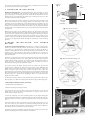
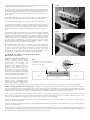
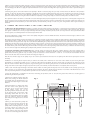
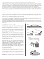
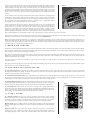
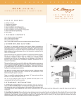
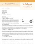
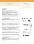
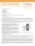
L
.
R
.
B
A
G
G
S
P
I
C
K
U
P
S
iMIX
INSTALLATION
MANUAL
&
USER'S
GUIDE
4 8 3
N .
F R O N T A G E
N I P O M O ,
C A
R D .
9 3 4 4 4
W W W . L R B A G G S . C O M
TABLE
OF
CONTENTS
1. Package Contents
2. Overview and Cautions
3. Strapjack Installation
4. iBeam installation: pin bridge guitars
5. iBeam installation: non-pin bridge guitars
6. iBeam installation: classical/nylon-string guitars
7. iBeam removal and repositioning
8. Element installation
9. iBeam gain control
10. Finishing the installation
11. User's guide (with controls diagram)
1.PAC K AG E
1
1
1
1
1
1
1
1
4
2
CO NT EN TS
(one) iMix preamp with pre-attached battery clip
(one) stereo pre-wired strapjack harness
(one) iBeam bridge plate transducer
(one) iBeam mounting fixture kit (not included with the iBeam Classical)
(one) Element undersaddle transducer
(one) Remote Control II soundhole controller
(one) flat cable for Remote Control II
(one) Battery Bag
(four) self-stick wire clips
(two) extra iBeam adhesive strips
2.OVERVIE W
AND
fig. 1
C AUTIONS
The L.R. Baggs iMix is an onboard stereo mixer that combines the iBeam
bridge plate transducer and the Element undersaddle pickup with an alldiscrete, class A, internal preamp. The system includes a soundhole-mounted
volume/mix control (the Remote Control II) and our Battery Bag.
We recommend that this system be installed by a professional dealer/installer.
We do not provide installation advice or support for home or hobbyist
installations. Installers: please read the instructions carefully before
proceeding. We will not be responsible for any damage to the guitar or personal injury resulting from installation, improper installation, use or
misuse of the product.
The iBeam fits x-braced guitars with at least three inches of flat open space directly under the saddle (see figure 1). Verify that this requirement is
met before making any alterations to the guitar.
If the space is too small to accommodate the iBeam, do not cut the iBeam to fit a tighter space.
The preamp requires a 9 volt battery, which is not included in this package.
There is a small slit under the iBeam cap about 1/2" from each end of the pickup. Do not poke anything into the slit.
The peel-and-stick adhesive is the best way to adhere the iBeam. It will hold the iBeam quite firmly, but will allow the pickup to be safely removed
at a later time. The use of any adhesive other than the provided self-stick pads is not recommended and will void the warranty.
Avoid unnecessary creasing or hard bending of the Element pickup.
Installation overview: The recommended installation procedure is to begin by installing the strapjack and plugging it (along with the Remote
Control II) into the correct preamp sockets. Following that, the iBeam should be installed, connected and tested to ensure optimum placement.
Then the Element should be installed, connected and tested to ensure proper sound and string balance. The preamp's gain setting should then be
adjusted so that the iBeam's level matches that of the Element. Finally, the preamp, Remote Control II and Battery Bag should be adhered to the
guitar and all wires should be secured with wire clips.
Each pickup should be installed and tested as if it were the only source in the system. Perfecting the sound of each pickup individually will
provide the most rewarding overall blend when you finally turn the mix knob
to 12:00 and hear the two sources together.
3.STR APJACK
fig. 2
tail
block
INSTALL ATION
Drilling the strapjack hole: For proper installation, this jack requires a clean
1/2" hole in the tail block of the instrument. If the guitar lacks this hole, start
by placing a piece of masking tape on the outside of the instrument over the
drilling area (to avoid chipping the finish), drill a small pilot hole in the tail
block and then follow with a step drill.
smaller
threaded
section
protrudes
Remove the strap ring, retaining nut and one washer from the end of the jack.
There should still be one star locking washer, one flat washer and a nut
remaining on the jack. Bring the jack down through the soundhole into the
body and insert it into the pre-drilled hole in the tail block. Using the internal
nut (be sure to include the flat and star washers), set the proper depth that
will allow the entire smaller threaded section to protrude from the instrument
(see figure 2).
fig. 3: primary location
With the jack in place, lay the remaining washer over the threads and attach
the external retaining nut until it’s tight. Finish by attaching the strap ring (it
should cover the retaining nut and washer). Asserting too much pressure may
crack the finish. Now bring the preamp into the guitar (do not adhere it yet),
connect a battery, and plug the strapjack cable into the "output" socket. Then
proceed to the appropriate iBeam installation instructions in the following
sections.
4 . i B E A M
GU ITARS
I N S TA L L AT I O N :
P I N
B R I D G E
4.1 General positioning guidelines: The iBeam is a highly sensitive pickup;
therefore, placement and the unique characteristics of the instrument are
critical factors in producing the outstanding results of which the iBeam is
capable. A few millimeters in any direction can have profound effects on the
quality of the sound. Because every guitar is different, we can tell you
approximately where the pickup should be placed, but we can not provide an
exact specification.
The iBeam is designed to attach to the bridge plate directly under the saddle
line and generally parallel to the saddle, with the attached peel-and-stick
adhesive. Good results should be consistently had by attaching the pickup as
shown in figure 3. However, because every guitar is unique, you may be
rewarded by searching for the optimum location.
fig. 4: alternative mounting area
In general, placing the iBeam directly under the saddle will provide the
greatest sense of immediacy, impact, snap and “string” sound. Offsetting the
pickup either toward the sound hole or toward the bridge pins in the area
shown in figure 4 will increase the amount of “body” in the sound and
generally have a more mellow and homogeneous tone with less midrange. We
have often achieved our very best results by placing the pickup as close to the
string ball-ends as is practical and offsetting it about 1 to 2 mm toward the
treble side of the saddle.
An alternative location that has often worked well, provided the x-braces are
wide enough, is to offset the pickup toward the front edge of the bridge plate.
4.2 Pin bridge installation (initial placement):
1. Assemble the mounting fixture.
2. Remove the strings from the pin holes.
3. Reach inside the hole and feel around under the bridge to be sure the
bridge plate is free from debris and obstructions. If you are unsure, stick a
mirror inside to inspect this area.
4. Place the stationary rod of the mounting fixture in the high-E bridge pin
hole and adjust the movable rod laterally in the slot until it drops into the lowE bridge pin hole as shown in figure 5. Tighten the nut to secure the movable
rod.
5. Place the adhesive dots on the fixture over the saddle (see figure 5), one on
each side of the big slot. Remove the adhesive backing from the dots and
position the iBeam over the fixture in the desired location. Stick the iBeam to
the adhesive dots on the fixture as shown in figure 6.
6. Remove the fixture and iBeam together from the bridge and remove the
adhesive backing from the bottom surface of the iBeam.
fig. 5
7. Insert the fixture holding the iBeam into the guitar. Find the high and low Estring bridge pin holes with the rods on the fixture.
fig. 6
8. Insert the rods into these holes and then elevate the fixture straight up until
the rods just poke out of the holes about 1/2". Grasp one of the rods from the
outside of the guitar and hold it. Do not pull up yet. While holding the one rod,
let go of the fixture inside of the guitar and grab the other rod on the outside
of the guitar.
9. Now pull straight up on the rods as shown in figure 7 to elevate the iBeam
until it contacts the bridge plate. Tug up on the rods to secure the pickup.
10. Pop the fixture off the iBeam inside the guitar and remove the fixture.
11. Press up firmly along the top surface of the iBeam, especially on the ends,
to secure it. It’s a good idea to press down on the bridge from the outside of
the guitar as you press up on the iBeam from the inside to equalize pressure
and avoid cracking the top. Wiggle the iBeam front to back a little as you
press.
12. Restring the guitar, connect the iBeam to the preamp's "iBeam" socket and
plug into your amp or PA. Connect the Remote to the preamp's "remote"
socket, turn the mix wheel completely to the iBeam, and test the pickup
placement. If the sound is satisfactory (see below for a definition of this),
secure the wire with a wire clip and turn to the Element installation in section
8. If the sound is unsatisfactory, see section 7. Do not test the pickup
placement without firmly securing the adhesive. Without completely securing
the pickup, the sound test will produce unreliable results.
fig. 7
The optimum location will deliver a sound that is focused and tight, with
proper string balance and good presence. It will capture enough of the string
resonance to be articulate, but will be mellowed by a full and strong body
resonance. Ultimately, it will accurately capture the distinct tone of the
instrument. An unsatisfactory location will often be characterized by a woofy
or nasal tone, poor string balance and a high sensitivity to feedback.
5.iBEAM INSTALL ATION: NON-PIN
BRIDGE GUITARS
5.1 General positioning guidelines: The
iBeam is a highly sensitive pickup;
therefore, placement and the unique
characteristics of the instrument are
critical factors in producing the
outstanding results of which the iBeam is
capable. A few millimeters in any
direction can have profound effects on
the quality of the sound. Because every
guitar is unique, you may be rewarded by
searching for the optimum location. With
non-pin bridge guitars, it is unlikely that
the first selected spot will be ideal.
fig. 8
This top-down view depicts the bridge with
the saddle removed. These pin hole locations
apply to all non-pin bridges.
saddle slot
drill pin hole here
iBeam
bridge
bridge
In general, placing the iBeam directly
under the saddle will provide the
greatest sense of immediacy, impact,
- 9 snap and “string” sound. Offsetting the
pickup either toward or away from the
sound hole will increase the amount of “body” in the sound and generally have a more mellow and homogeneous tone with less midrange.
tie block
5.2 Non-pin bridge installation (initial placement): Installation on non-pin bridge guitars requires that you remove the saddle, drill a small hole
in each end of the saddle slot, and insert guide pins to act as a reference when locating the iBeam. The hole locations will correspond to the small
slots in the bottom of each end of the iBeam (see figure 8). A good starting place is to drill the holes so that the iBeam will be centered under the
E strings. You will need an inspection light, inspection mirror, drill, 1/16" drill bit, matchsticks or toothpicks, and a short pencil.
1. Drill a 1/16" hole through the bridge at both ends of the saddle slot. If the guitar already has a hole in the saddle slot for a pickup, you may be
able to use this as one of the holes. The minimum distance between the holes should allow the notches in each end of the iBeam's base to nest
over the protruding matches or toothpicks that you will insert as a reference to place the iBeam.
2. Press the matches or toothpicks into the holes until they just protrude (1/16" to 1/8") into the guitar. These will act as locating pins for
determining the iBeam's placement.
3. Remove the adhesive backing from the iBeam and, holding the iBeam between your thumb and two middle fingers, use your index and little
fingers to locate the matches.
4. Hold the iBeam at a slight angle away from the inside of the guitar top, and, using the slot in one end of the bottom of the iBeam, locate one of
the protruding matches. Rotate the other end of the pickup until you find the other protruding match with the other slot. Then very lightly press
the adhesive against the bridge plate with just enough pressure to hold it in place.
5. Once you have tacked the pickup into place, insert an inspection mirror into the body to check the placement of the pickup. After confirming
that it is located correctly, remove the guide pins and press firmly with a little rocking motion over the surface of the top of the pickup to secure
it to the bridge plate. Be sure to apply an equal downward force to the top of the bridge when pressing up from the inside to prevent damage to
the guitar.
6. Restring the guitar, connect the iBeam to the preamp's "iBeam" socket and plug into your amp or PA. Connect the Remote to the preamp's
"remote" socket, turn the mix wheel completely to the iBeam, and test the pickup placement. If the sound is satisfactory (see below), secure the
wire with a wire clip and turn to the Element installation in section 8. If the sound is unsatisfactory, see section 7. Do not test the pickup
placement without firmly securing the adhesive. Without completely securing the pickup, the sound test will produce unreliable results.
The optimum location will deliver a sound that is focused and tight, with proper string balance and good presence. It will capture enough of the
string resonance to be articulate, but will be mellowed by a full and strong body resonance. Ultimately, it will accurately capture the distinct tone
of the instrument. An unsatisfactory location will often be characterized by a woofy or nasal tone, poor string balance and a high sensitivity to
feedback.
6. iBEAM
INSTALL ATION: CL ASSIC AL
GUITARS
6.1 General positioning guidelines: The iBeam is a highly sensitive pickup; therefore, placement is a critical factor in producing the outstanding
results of which the iBeam is capable. A few millimeters in any direction can have profound effects on the quality of the sound. In short, because
each guitar is different, we can tell you approximately where the pickup should be placed, but we can not provide an exact specification. With
classical guitars, it is unlikely that the first selected spot will be ideal.
The classical iBeam has a tunnel in the center of the pickup designed to clear the middle fan brace. The tunnel is wide enough to allow for some
lateral movement of the pickup.
We suggest that you initially position the pickup so it is laterally centered over the brace and that the entire pickup is offset towards (and parallel
to) the tie block by 2 to 5 mm. The idea is to blend the direct string sound with the sound of the body. The more centered the pickup is under the
saddle, the more string drive and "snap" the sound will have. Offsetting the pickup towards the tie block or even towards the sound hole by a few
millimeters will allow more body sound to mix with the string sound. If you desire more presence from the bass strings and wish to mellow out
the high strings, center the pickup under the bass strings and angle it so the center of the pickup's high string end is either in front of or behind
the saddle line by some amount. Reversing this will result in more presence for the high strings and less for bass. If you find that the small E string
does not have enough level, offsetting the pickup laterally towards it will increase its volume.
6.2 Classical installation (initial placement): Most classical guitars are fan braced. The most common bracing is the Torres pattern with 5
longitudinal braces. The iBeam is notched in the middle of the pickup to straddle the middle fan brace and will fit most Torres-pattern-braced
guitars. Classical bracing patterns vary, so before you proceed, check to ensure that there is a total of 3" of clean, flat area between the two
braces on both sides of the center brace under the bridge (see figure 9).
Note: Do not trim the edges of the pickup if you do not have space between the braces for the pickup. This will ruin the pickup and void the
warranty!
Installation on classical guitars requires that you remove the saddle, drill a small hole in each end of the saddle slot, and insert guide pins
(matchsticks or toothpicks work well) to act as a reference when placing the iBeam. The hole locations will correspond to the small slots in the
bottom of each end of the iBeam (see figure 8). A good starting place is to drill the guide pin holes so that the iBeam will be centered under the E
strings. You will need an inspection light, inspection mirror, drill, 1/16" drill bit, wooden matchsticks or toothpicks, and a short pencil.
1. Drill a 1/16" hole through the bridge at both ends of the saddle slot. If the guitar already has a hole in the saddle slot for a pickup, you may be
able to use this as one of the holes. The minimum distance between the holes should allow the notches in each end of the iBeam's base to nest
over the protruding matches or toothpicks that you will insert as a reference to place the iBeam.
2. Press the matchsticks or toothpicks into the holes until they just protrude (1/16" to 1/8") into the guitar. These will act as locating pins for
determining the iBeam's placement.
3. Remove the adhesive backing from the
iBeam and, holding the iBeam between
your thumb and two middle fingers, use
your index and little fingers to locate the
matches.
fig. 9
sound hole
alternate placement
range (light gray area)
4. Hold the iBeam at a slight angle away
from the inside of the guitar top, and,
using the slot in one end of the bottom
of the iBeam, locate one of the
protruding matches. Rotate the other end
of the pickup until you find the other
protruding match with the slot in the
other end of the iBeam. Then very lightly
press the adhesive against the bridge
plate with just enough pressure to hold it
in place.
5. Once you have tacked the pickup into
place, insert an inspection mirror into the
body to check the placement of the
pickup. After confirming that it is located
correctly, remove the guide pins and
press firmly with a little rocking motion
over the surface of the top of the pickup
to secure it to the bridge plate. Be sure to
tie block
iBeam default position
saddle
(dark gray area)
apply an equal downward force to the top of the bridge when pressing up from the inside to prevent damage to the guitar.
6. Restring the guitar, connect the iBeam to the preamp's "iBeam" socket and plug into your amp or PA. Connect the Remote to the preamp's
"remote" socket, turn the mix wheel completely to the iBeam, and test the pickup placement. If the sound is satisfactory (see below for a
definition of this), secure the wire with a wire clip and turn to section 8. However, with classical guitars, it is likely that the results will be less than
optimum at this position. If this is the case, we encourage you to experiment with alternative placements (see section 7). Do not test the pickup
placement without firmly securing the adhesive. Without completely securing the pickup, the sound test will produce unreliable results.
The optimum location will deliver a sound that is focused and tight, with proper string balance and good presence. It will capture enough of the
string resonance to be articulate, but will be mellowed by a full and strong body resonance. Ultimately, it will accurately capture the distinct tone
of the instrument. An unsatisfactory location will often be characterized by a woofy or nasal tone, poor string balance and a high sensitivity to
feedback.
7.iBEAM
REMOVAL
AND
REPOSITIONING
The adhesive used to secure the iBeam is very strong. Once you stick it down, it will increase its grip over about a week’s time. If you wish to
experiment with placement, it will be easier before the adhesive develops its full strength. To experiment with placement, begin by outlining the
pickup in its current position with a pencil; this will act as a reference of the initial location. Next, place three fingers along the length of the back
side of the pickup. Pull firmly with even pressure towards the soundhole until the adhesive gives way. Rock it up onto one edge and then lift up
one end to pull the adhesive away from the bridge plate. Do not pull up on the cap. Because the iBeam relies on a clean connection with the
guitar body, we do not recommend re-using the adhesive; instead, use a new strip.
To remove the adhesive from the bottom of the pickup, roll it off like carpet. After tacking the new pad to the bottom of the pickup, use the edge
of a pencil to press the adhesive firmly to the pickup. Two extra pads are included in the kit, and extra pads are available in packs of 10 for $5.00.
Inspect the bridge plate for any adhesive residue before you reposition the iBeam.
Now reposition and test the pickup. Remember that moving the pickup towards the saddle will increase presence and string response, while
moving it away from the saddle will increase warmth and body response. If the sound is satisfactory, secure the wire and continue to the next
section. If not, continue repositioning the iBeam as needed until you find the
proper location.
8.ELEMENT
INSTALL ATION
fig. 10
extension
8.1 Installation notes: For optimum performance of the Element, the bridge
slot must have a clean, flat surface free of any debris or over-spray from the
finish. The slot must be a minimum of .125” (1/8”) deep, but we suggest a
depth of at least .187" (3/16”) to avoid excessive saddle tilt.
The commonly-known 50/50 rule applies: The amount of saddle visible above
the bridge surface (with pickup installed) should be no greater than the
amount of saddle in the slot beneath the bridge surface; otherwise the
balance and output of the pickup may suffer.
8.2 Short saddle note: The first 1/8" of the Element pickup is not active. If you
do not have a minimum of 1/4" of saddle beyond the E strings, you may
experience low output on these strings. To remedy this, drill a small horizontal
hole in the end of the slot to extend the pickup further under the saddle (see
figure 10). To drill this hole without disrupting the floor of the saddle slot,
place a small jeweler's screwdriver under the tip of the drill bit. On short
saddles we also advise that the pickup exit hole be drilled into the end wall of
the saddle slot rather than the slot's floor (see figure 12) to likewise extend
saddle/pickup contact at the exit end. Again use the jeweler's screwdriver to
protect the saddle floor as you drill.
8.3 Installation: Remove the strings from the guitar. To duplicate the string
height exactly, scribe a line along the front edge of the saddle where it
extends above the bridge. The line will later be used as a guide when
removing material from the bottom of the saddle to compensate for the
thickness of the pickup (.037” total). Remove the saddle to drill the hole for the
pickup. The drill bit needs to be as large as the saddle slot will allow.
Inspect the inside of the guitar and note the position of the braces and the
iBeam in relation to the saddle slot. Drill at either end of the slot on the side
that will enable you to avoid all braces as you penetrate the top, as shown in
figure 13. Do not drill through the iBeam! Blow out the slot with compressed
air and check for remaining debris.
Important: Round the inside of the hole where it meets the bottom of the slot
with a small, sharp knife or small file to avoid pinching the pickup as the
saddle lies on it.
fig. 11
fig. 12
drill bit
jeweler's screwdriver
short saddle:
drill side wall
normal saddle:
drill floor
fig. 13
This view depicts the bridge at an angle that is
level with the guitar top and perpendicular to
the saddle slot. Note the rounded edge where
the hole has been drilled.
drill bit
slot
bridge
guitar top
brace
iBeam
fig. 14
Feed the pickup into the slot from inside the guitar with either side up.
Inserting a toothpick or similar object through the hole from the outside is
helpful in finding the location of the hole on the inside of the guitar.
Important: The fit of the saddle in the slot is the single most important factor
in this installation. It is crucial that the bottom of the slot and the lower
proper saddle-pickup contact
(saddle lean exaggerated)
surface of the saddle be flat to make even contact with the pickup. The saddle should fit
loosely enough in the slot that it can be pulled out with your fingertips. It will then have a
slight forward lean when the strings are under tension. It is absolutely necessary to
compensate for this slight lean by sanding a tilt in the bottom of the saddle so it still sits
flat on the pickup when the strings are at tension (see figure 14). If the saddle is too tight,
binds at all or is too loose, this will have a negative effect on the string balance and
output.
fig. 15
Set the saddle in the slot, noting how much material must be removed to compensate for
the thickness of the pickup. Sand the bottom surface of the saddle on a belt sander until
the scribe line is just above the bridge top. Finish sanding the bottom by hand. It is best to
do this against a machined flat surface with fine sandpaper. Use a straightedge with a
strong light source to inspect the flatness of your saddle.
Insert the pickup all the way into the slot, place the saddle on top of it, and temporarily
secure it with a piece of tape. Secure the wire with a wire clip as close to the exit hole as is
practical, with a one- to two-inch service loop. Failure to secure the wire may produce
boominess and feedback. Now plug the Element into the preamp's "pickup" socket,
restring the guitar, plug into your amp or PA and turn the mix knob completely to the
Element. Confirm that the EQ controls are at their default positions and test the Element,
paying careful attention to string balance. If the sound is satisfactory, proceed to the next section. If not, read on.
String balance problems are almost always the result of an uneven interface between the bottom of the saddle and the saddle slot. If the string
balance is uneven, check these surfaces to ensure that they are both completely flat.
Tip: A segmented packaging knife blade is a useful tool in determining the flatness of the saddle slot. Break off enough blade segments so as
much of the blade fits into the slot as possible. Briefly use a back-and-forth scraping motion to see if the slot bottom scrapes evenly. Any high or
low spots will be readily apparent. A minor low spot in the slot may be compensated for by shims under the pickup; however, for gaps over .005"
or multiple gaps, we recommend rerouting the slot.
9.iB EAM
G AIN
CO NTROL
The likelihood of the iBeam and Element gain levels being naturally equal is extremely low. Therefore we have provided a gain control that affects
only the iBeam channel, which is located on the upper right corner of the preamp. Setting this is an essential step in perfecting the mix. To adjust
this correctly, you will need a small Phillips screwdriver.
First, make sure everything is plugged in and turned on, and rotate the mix wheel completely to the Element. Now test the overall volume of the
Element by playing all the strings in your normal playing style. Then rotate the control completely to the iBeam and do the same. Note the
difference between the two pickups.
Now adjust the gain control accordingly. To increase the gain, rotate the screw clockwise; to decrease the iBeam gain, rotate the screw
counterclockwise.
Once the gain has been adjusted, again test both pickups individually, using the mix knob to pan between the two. If the outputs differ, repeat
these steps as necessary to make them equal.
10.FINISHING THE
INSTALL ATION
10.1 Preamp placement: The preamp should be mounted on the back surface of the guitar, with the pre-set controls on the unit accessible
through the soundhole (see figure 15). Clean all dust and oil from the area inside the guitar where the preamp will be mounted, remove the
adhesive backing and press the unit into place.
10.2 Remote Control II placement: Find a comfortable and convenient place to affix the Remote at the edge of the sound hole -- most users will
find it best to position the unit on the side of the soundhole that will be above the strings when playing. Clean the desired placement area
completely, peel off the adhesive backing, and stick once. See section 11.2 for usage details.
10.3 Battery Bag placement: Stick the double-sided adhesive to an easily accessible spot
inside of the guitar near the preamp. Insert the battery and battery clip into the bag. The
battery can then be changed by opening the flap on the bag and pulling out the battery.
GUIDE
iBeam mid cut: This dial adjusts the iBeam's midrange frequencies around 900Hz.
Rotating the control completely clockwise will give the iBeam full midrange output and
essentially deactivates this control. The counterclockwise end reduces this part of the
60 640
-9dB 0dB
MID
-9dB 0dB
MONO
REMOTE
iBeam low cut: This is a 12dB/octave low cut that adjusts the iBeam's low-end cutoff from
60Hz to 640Hz. Make sure that the mix control is panned completely to the iBeam before
testing.
MID
OUTPUT
11.1 Preamp controls: There are five controls along the right exterior of the preamp:
iBeam gain, iBeam low cut, iBeam mid cut, Element mid cut and stereo/mono. The gain
control is covered in section 9. Setting the rest of these controls properly is an essential
part of perfecting your sound. To set these controls, you will need a small screwdriver.
LO HI
LOW
CUT
PICKUP
11.USER'S
GAIN
iBEAM
10.4 Securing wires: Now secure all loose wires using the wire clips provided. There
should be one for each pickup, along with clips for the Battery Bag and Remote Control II.
Leave a small service loop for each wire, but make sure they will not hit the inside of the
guitar during on-stage movement (the pickups will sense this contact).
fig. 16
STEREO
ON
output by 9dB.
Element mid cut: This control has the same operation as the iBeam mid cut, but affects the Element. Be sure to have the mix control panned
completely to the Element when testing this setting.
Stereo/mono: This determines whether the output is summed to one mono channel or split into two signals. Stereo mode requires the use of a
standard stereo cable or stereo Y cable -- this mode puts the Element on the tip channel and the iBeam on the ring channel. If you use a mono
cable in stereo mode, only the Element will be present. This setting is useful for recording each pickup independently, creating separate blends
for two different sets of speakers (for example, the house speakers and stage monitors), or applying different effects to each channel. The
following section describes how the Remote Control II operates in stereo and mono modes.
11.2 Using the Remote Control II: In mono mode, the volume wheel controls the levels of both channels equally -- rotate the wheel towards the
neck to increase the master volume. The mix control determines the amount of each pickup in the overall blend. Rotate the wheel completely
towards the neck for 100% iBeam, and completely towards the saddle for 100% Element. The 12:00 position will give both pickups equal output.
For most applications, an equal blend of both sources should provide an effective balance between the iBeam's warmth, fidelity and body
sensitivity, and the Element's presence and stability. For recording or intimate venues (especially when soloing), favoring the iBeam may elicit a
warmer, richer, more natural tone. When playing in loud environments or with an ensemble, favoring the Element will provide more "cut," which
will help bring the guitar through the mix.
In stereo mode, each wheel becomes assigned to an individual pickup and controls the output of that source independently. In this instance, the
"vol" wheel controls the Element output and the "mix" wheel controls the iBeam.