1
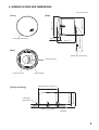
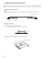
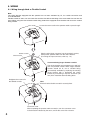
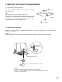
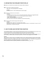
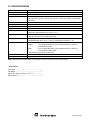
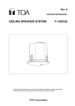
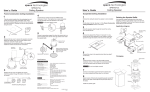
Rev. A
INSTRUCTION MANUAL
CEILING SPEAKER SYSTEM
F-2852CU2
Please follow the instructions in this manual to obtain the optimum results from this unit.
We also recommend that you keep this manual handy for future reference.
TABLE OF CONTENTS
1. SAFETY PRECAUTIONS ............................................................................... 3
2. GENERAL DESCRIPTION ............................................................................. 4
3. FEATURES .......................................................................................................... 4
4. NOMENCLATURE AND DIMENSIONS ..................................................... 5
5. MOUNTING HARDWARE INSTALLATION ............................................... 6
6. WIRING
6.1. Wiring through Hard or Flexible Conduit ........................................................... 8
6.2. Wiring with Naked Cables ................................................................................ 9
7. CABLE CONNECTION TO INPUT CONNECTOR ................................. 10
8. SPEAKER INSTALLATION ........................................................................... 11
9. REMOVING THE SPEAKER FOR MAINTENANCE
9.1. Detaching the Front Grille ............................................................................... 13
9.2. Removing the Speaker ................................................................................... 13
10. REPAINTING THE SPEAKER FRONT GRILLE ...................................... 14
11. INPUT OVERLOAD PROTECTION FUNCTION .................................... 14
12. SAFETY AGENCY COMPLIANCE ............................................................. 15
13. SPECIFICATIONS ............................................................................................ 16
Accessories ............................................................................................................. 16
2
1. SAFETY PRECAUTIONS
• Be sure to read the instructions in this section carefully before use.
• Make sure to observe the instructions in this manual as the conventions of safety symbols and messages
regarded as very important precautions are included.
• We also recommend you keep this instruction manual handy for future reference.
Safety Symbol and Message Conventions
Safety symbols and messages described below are used in this manual to prevent bodily injury and property
damage which could result from mishandling. Before operating your product, read this manual first and
understand the safety symbols and messages so you are thoroughly aware of the potential safety hazards.
WARNING
Indicates a potentially hazardous situation which, if mishandled, could
result in death or serious personal injury.
CAUTION
Indicates a potentially hazardous situation which, if mishandled, could
result in moderate or minor personal injury, and/or property damage.
WARNING
• Use the specified mounting hardware in
combination. Doing otherwise may cause the unit
or component to fall off, resulting in personal injury.
• Leave the installation to your TOA dealer because
the installation requires expert knowledge.
Improper installation may cause the unit to fall,
resulting in personal injury and/or property
damage.
• Should the following irregularity be found during
use, immediately stop operating the unit and
contact your nearest TOA dealer. Further attempt
to use under this condition may cause fire or
electric shock.
• Install the unit in a location that can structurally
support the weight of the unit and its mounting
hardware. Doing otherwise may result in the unit
falling down and causing personal injury and/or
property damage.
· If you detect smoke or a strange smell coming
from the unit
· If no tone sounds
• Do not use other methods than specified to mount
the unit. Extreme force is applied to the unit and
the unit could fall off, possibly resulting in personal
injuries.
• Attach the safety wire to the unit. If not attached,
the unit could fall off, resulting in personal injury.
CAUTION
• Avoid installing the unit in humid or dusty locations,
in locations exposed to the direct sunlight, near the
heaters, or in locations generating sooty smoke or
steam as doing otherwise may result in fire or
electric shock.
• Tighten each screw securely. Ensure that the unit
has no loose joints after installation to prevent
accidents that could result in personal injury.
• Do not operate the unit for an extended period of
time with the sound distorting. This is an indication
of a malfunction, which in turn can cause heat to
generate and result in a fire.
• Never hold the tweeter section as a handle to carry
the unit during installation. If the diffuser breaks off,
the unit could fall from an elevated position,
resulting in possible personal injury.
• Avoid touching the unit's sharp metal edge to
prevent injury.
3
2. GENERAL DESCRIPTION
The F-2852CU2 is a flush-mounted Ceiling Speaker System that offers a wide frequency range of high-quality
sound output. It is specifically designed to be mounted to a drop ceiling with use of the supplied tile bridge.
3. FEATURES
• Two-way bass-reflex speaker system designed to provide a wide frequency range and high power handling
capability.
• Ideal for locations that have high ceilings or require true-to-life sounds.
• Uniform sound output levels are achievable not only in the position directly under the speaker, but also over
a wide radius. (Coverage angle is approximately 110°.)
• Because the speaker is provided with both low- and high-impedance operating capability, it can be used in
many different applications. Front panel-mounted input selector switch permits easy verification and change
of current impedance settings.
• Easy installation. Can be quickly and accurately mounted to ceilings.
• Rotating front grille can be installed quickly and conveniently.
• Attractive exterior design specially created by an interior designer blends naturally with any architectural
space, enhancing the immediate area's sense of harmony.
4
4. NOMENCLATURE AND DIMENSIONS
Unit: mm (inches)
ø245 (9 41/64)
[Side]
Approx. 600 (23 5/8)
ø280 (11 1/32)
[Front]
38 (1 1/2)
Front grille (accessory)
236 (9 2/8)
[Rear]
Safety wire (accessory)
Safety wire hook
Mounting hole: ø250 (9 27/32)
Tile bridge
(accessory)
Max. 202 (7 61/64)
[Ceiling mounting]
Choke bracket
Max. 37 (1 29/64)
Connector cover
Ceiling tile
5
5. MOUNTING HARDWARE INSTALLATION
Before mounting the speaker, check the ceiling structure is of drop ceiling with 2-foot standard ceiling tiles.
[Installation view on Drop Ceilings]
Caution
Set the tile bridge so that both ends fit securely into the T-grids, even if the ceiling tile accidentally falls off.
Tile bridge (accessory)
T-grid
Ceiling tile
[Installation procedures]
Step 1. Cut a ø250 mm (9 27/32") hole in the ceiling.
Use the supplied paper pattern to position and trace the hole.
ø250 ±5 mm (9 27/32 ±13/64")
Ceiling tile
Step 2. Place the supplied tile bridge on the 2-foot tile as shown below.
Tile bridge (accessory)
2-foot tile
T-grid
6
Step 3. Attach a safety wire to prevent the speaker from accidentally falling.
To attach, tie one end of the supplied safety wire around the speaker's safety wire hook, and tie its
snap ring around a secure C-channel bar or suspension pipe.
Safety wire (accessory)
Secure C-channel bar or
suspension pipe
Tile bridge (accessory)
2-foot tile
T-grid
Ceiling tile
Safety wire (accessory)
Safety wire hook
Speaker unit
7
6. WIRING
6.1. Wiring through Hard or Flexible Conduit
Note
The choke bracket equipped with the speaker has not been evaluated by UL, for conduit connection and
UL514B Standard.
Flexible conduit of 3/8 or 1/2 inch trade size and the UL514B conduit fitting of the same trade size can also be
used. When using the UL514 listed conduit fitting, detach the equipped choke bracket and mount the conduit
fitting instead.
Loosen the screw to allow the speaker cable to pass through.
Flexible conduit
Choke bracket
Plug the wired input connector into the speaker's socket,
then pull the speaker cable from the choke bracket.
(For wiring the input connector, refer to p. 10.)
Accommodating larger diameter conduit
The choke bracket accommodates up to 3/8-inch
(9.5 mm) flexible conduit. When larger diameter
conduit should be fit, use a suitable fitting
commercially available by replacing the existing
choke bracket with it. Detaching the choke
bracket by unscrewing it exposes a 7/8-inch (22
mm) hole. Install the alternate fitting there.
Retighten the screw to fix
the flexible conduit.
Note
Ensure that the flexible conduit is securely fixed.
Connector cover
After completing the speaker cable connection, turn the connector cover
in the direction indicated by the arrow, and fix the cover with 2 screws.
8
6.2. Wiring with Naked Cables
Loosen the screw to allow the speaker cable to pass through.
Plug the wired input connector into the speaker's socket,
then pull the speaker cable from the choke bracket.
(For wiring the input connector, refer to p. 10.)
Choke bracket
Retighten the screw to fix
the speaker cable.
Note
Ensure that the speaker cable is securely fixed.
Connector cover
After completing the speaker cable connection, turn the connector cover
in the direction indicated by the arrow, and fix the cover with 2 screws.
9
7. CABLE CONNECTION TO INPUT CONNECTOR
Recommended cable types
• Solid copper wire:
ø1.0 – ø1.6 mm
(equivalent to AWG 18 – 14)
• Stranded copper wire: 0.75 – 2.5 mm2
(equivalent to AWG 18 – 14)
Cover mounting screw
Step 1. Loosen the 2 cover mounting screws, and rotate the
connector cover in the direction indicated by the
arrow in the figure at right.
Speaker unit
Connector cover
Removable input
connector
Step 2. Detach the removable input connector from the
speaker's socket, and loosen the screw of the
terminal to be used.
Speaker unit
Step 3. Insert the stripped cable end into the terminal and tighten the terminal screw with a screwdriver.
[If not bridging]
Note
If not making bridge connections,
be sure to tighten unused terminal
screws to avoid their vibration.
[If bridging]
From Amplifier
5 mm
(13/64")
To the
next speaker
10
8. SPEAKER INSTALLATION
Caution
Before mounting, check to be sure that the speaker's
4 mounting tabs are turned inside the unit as shown
in the figure.
If turned outward, the speaker cannot be inserted
through the mounting hole.
In
Out
Mounting tab
Step 1. Insert the speaker through the mounting hole till it
contacts the ceiling panel. While doing so, avoid
directly touching the speaker's diffuser section.
WARNING
Mounting hole
Never hold the tweeter section as a handle to
carry the speaker during installation. If the
tweeter section breaks off, the unit could fall
from an elevated position, resulting in possible
personal injury.
Tweeter section
Tweeter section
Step 2. Rotate and tighten the mounting tab axis screws (4 places) on the unit clockwise to their full stop in
order to grip the ceiling panel with the mounting tabs.
Mounting tab
Mounting tab axis screw
Use an electric screwdriver to tighten.
(Tightening torque: 6 – 10 kgf·cm)
11
Step 3. Set the input power.
Turn the input selector switch (on the unit's front) to
set it to the desired input impedance.
(Factory-preset to 170 Ω.)
Step 4. Attach the front grille.
Align the tabs (4 places) on the back side of the grille
with the corresponding notches in the unit, then rotate
the grille to full stop in the direction indicated by the
"LOCK" arrow.
Tip
The front grille employs a double-locking system that
clicks into place once partway through rotation, but
only locks into position at its point of full rotation.
Always be sure to rotate the grille to its full stop.
F-2852CU2
3.3kΩ
1.5W
0.2W
670Ω
7.5W
0.9W
330Ω
170Ω
83Ω
15W
30W
60W
1.9W
3.7W
7.5W
Speaker
unit
Notch (4 places)
LOCK
Front grille
(accessory)
12
Tab (4 places)
9. REMOVING THE SPEAKER FOR MAINTENANCE
9.1. Detaching the Front Grille
1
Turn the front grille counterclockwise to full stop, then lightly
pull it downward.
Tip
The front grille employs a double-locking system.
If the grille cannot be detached when lightly pulled downward,
it likely has not yet been fully rotated back to the detachment
position. In such cases, take care to rotate the grill fully
counterclockwise in order to release the lock.
Unlock
Front grille
2
Pull lightly.
9.2. Removing the Speaker
Rotate the 4 mounting tab axis screws counterclockwise. The mounting tabs rise as they turn, allowing the
speaker to be removed.
Caution
When loosening the mounting tab axis screws, support the speaker by hand to prevent it from falling.
Screw cap
Mounting tab
Mounting tab axis screw
Use an electric screwdriver to detach.
Caution
Be sure to set the screwdriver's torque for under 4 kgf·cm.
Failure to do so may cause the Screw cap and the Mounting tab to fall off
on the rear of ceiling panel.
13
10. REPAINTING THE SPEAKER FRONT GRILLE
Note: Be sure to detach the front grille from the speaker before repainting.
Step 1. Clean the front grille before painting.
Wipe with a soft cloth dampened in a detergent.
Caution
Do not use thinner or other volatile liquids to clean the grille.
Step 2. Spray on a uniform, thin coat of paint.
Cautions
• Avoid painting with a roller or brush, as the grille mesh holes could become clogged with paint.
• Use appropriate spray paints for the front grille (grille and frame) materials.
Grille: Rolled steel plate
Frame: Fire-resistant ABS resin (acrylic paint)
• Be sure to follow the directions indicated on the paint when painting.
Step 3. After the paint has dried, apply another light coat.
Caution
Repeating Step 2, apply two or more light coats of paint.
Application of one thick coat of paint all at once may cause drips or unevenness to show up in the
painted finish, or clog the mesh holes.
11. INPUT OVERLOAD PROTECTION FUNCTION
The F-2852CU2 features an internal input overload protection circuitry. If an extremely high input level is fed
to the unit, the protection circuitry automatically cuts off the signal to the speaker element.
A drastic reduction in sound volume indicates that the protection circuitry has been enabled.
In such cases, simply reduce the amplifier volume. The protection circuitry will automatically reset in
approximately 10 seconds. After reset, try to maintain the volume at a level slightly lower than before.
Caution
This protection circuitry does not completely protect the unit against extremely high input power levels.
Depending on the type or duration of excessive power input, the protection circuitry might not be enabled,
resulting in damage to the speaker element. Also, if the excessive power input continues for a long period of
time, the circuitry may not be capable of resetting to its original condition.
Use the system with care so that the speakers are not exposed to excessive power input.
14
12. SAFETY AGENCY COMPLIANCE
This product is for indoor use only.
• General signaling speaker, UL1480 Category UEAY and CAN/CSA C22.2 No. 205 Category UEAY7
Products Listed under these categories are suitable for use in general (non-fire alarm) signaling service in
conjunction with compatible Listed audio equipment, the combination of which is intended to be installed in
accordance with the applicable requirements of the National Electrical Code (NEC) and the local authority
having jurisdiction.
• Suitable for use in air-handling spaces (UL2043)
Fire Test for Heat and Visible Smoke Release for Discrete Products and their Accessories Installed in AirHandling Spaces (1998) - NFPA 70 National Electrical Code (NEC) 2002, Article 300-22 (c) and NFPA 90A
Installation of air-conditioning and ventilation systems, section 2-3.10.1 (a) exception 3.
[Output power vs. switch settings for 25 V and 70 V line operation]
The rotary switch on the F-2852CU2's front panel permits selection of speaker handling power on 25 V or 70
V line operation as shown in the table below.
Setting Position
1.5 W
7.5 W
70 V Line
15 W
30 W
60 W
0.2 W
0.9 W
25 V Line
1.9 W 3.7 W
7.5 W
15
13. SPECIFICATIONS
Enclosure
Rated Input
Power Handling Capacity
Impedance
Frequency Response
Sound Pressure Level
Speaker Component
UL Cord
Mounting Hole
Input Terminal
Usable Cable
Finish
Dimensions
Weight
Bass reflex type
60 W (High Impedance)
Continuous pink noise: 90 W (8 Ω), 60 W (16 Ω),
70 V line: 83 Ω (60 W), 170 Ω (30 W), 330 Ω (15 W), 670 Ω (7.5 W), 3.3 kΩ (1.5 W)
25 V line: 83 Ω (7.5 W), 170 Ω (3.7 W), 330 Ω (1.9 W), 670 Ω (0.9 W), 3.3 kΩ (0.2 W)
16 Ω, 8 Ω
60 – 20,000 Hz
91 dB (1 W, 1 m)
High frequency: Dome-type, Low frequency: 16 cm (6 1/2") cone-type
UL1480 (UEAY), UL2043, CAN/CSA C22.2 No.205 (UEAY7)
ø250 mm (9 27/32")
Maximum ceiling thickness: 37 mm (1 29/64")
Removable locking connector with screw-down terminals
(2 input terminals and 2 bridge terminals)
Solid copper wire:
ø1.0 – ø1.6 mm (equivalent to AWG 18 – 14)
Stranded copper wire: 0.75 – 2.5 mm2 (equivalent to AWG 18 – 14)
Enclosure:
Steel plate, plating
Baffle:
Fire-resistant ABS resin (resin material grade: UL-94 V-0 or
its equivalent), black
Rim:
Fire-resistant ABS resin (resin material grade: UL-94 V-0 or
its equivalent), white, paint
Punched net: Steel plate, white, paint
ø280 mm (11 1/32") x Depth 236 mm (9 2/8")
5.8 kg (including mounting accessories)
Note: The design and specifications are subject to change without notice for improvement.
• Accessories
Front grille ............................................................ 1
Tile bridge ............................................................ 1
Safety wire (approx. 60 cm or 23 5/8") .................. 1
Paper pattern ....................................................... 1
533-06-148-00