1
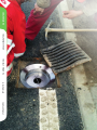
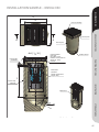
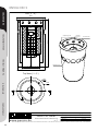
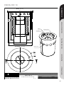
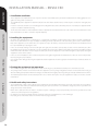
ENVIA CRC STORAGE TANKS INFILTRATION PUMPING STATIONS GREASE SEPARATORS OIL SEPARATORS OIL SEPARATOR – ENVIA CRC OIL SEPARATORS The ENVIA CRC is installable into commercially available gully-holes through various adapters. It is recommended to install these equipments in parking lots, or in road sections with existing hazards of oil-contamination or drift. This equipment can be installed both in already existing facilities and in those being under construction. GREASE SEPARATORS The technical advantages of the equipment – Installable also in existing storm water-drainage systems, – Made from corrosion proof materials, – Simple and fast installation with minimum tooling requirements, – Compact design – Fast installation ENVIA CRC / CRC + drift- and light liquid separator equipment installable in gully holes ENVIA® CRC / CRC + drift- and light liquid separator equipment installable in gully holes, for 5 mg/l TPH limit values for the territorial categories 2. 3. and 4. under Annex 2 of the Regulation 28/2004. (XII. 25.) KvVM. Rated output l/s Mass ø [mm] h [mm] m [kg] ENVIA® CRC 5 5 330 600 38 ENVIA® CRC 10 10 440 600 53 PUMPING STATIONS Article number Inclusive dimensionss INFILTRATION STORAGE TANKS 43 OIL SEPARATORS DESIGN AID – ENVIA CRC I. Product Description 1. The denomination and designation of the product Denomination: ENVIA® 5/10 drift and light liquid separator equipment that can be installed into open surface rainwater drainage conduits and ditches. Denomination:ENVIA® 5/10 GREASE SEPARATORS 2. The denomination of the manufacturer and distributor of the product Manufacturer: PURECO Environmental and Economic Service Kft. 1118 Budapest, Rétköz utca 5. Distributor: PURECO Environmental and Economic Service Kft. 1118 Budapest, Rétköz utca 5. 3. The name and address of the applicant (the rightful owner of the licence) PURECO Environmental and Economic Service Kft. 1118 Budapest, Rétköz utca 5. PUMPING STATIONS 4. The legal regulations on the basis of which the licence is issued, and the documentation that verifies the suitability of the product – Section 62 of Act no. LXXVIII of 1997 on the development and protection of built environment. – The Joint Decree no. 3/2003. (1.25) BM-GKM-KvVM on the specified rules of the technical requirements, suitability verification, marketing, and use of building products – The no 8001/2006. (K.V. Ért. 5.) KvVM information issued by the Minister of Environmental Protection and Water Conservancy on the approving organization that is entitled to issue or withdraw a technical licence for building concerning the building products used exclusively for water conservancy type of structures. – An expert’s opinion of the subject number 721/17/743701 entitled ”The Examination of ENVIA® drift and light liquid separator equipment” compiled by VITUKI Kht. in October 2007. – The Technical Conditions entitled ”ENVIA® 5/10 drift and light liquid separator equipment” and marked as ”PURECO-MF-2-2007”, which were issued by PURECO Kft on 8 August 2007. 5. The product’s usage area Before the rainwater that is contaminated with mineral oil and settling or floating drift is conducted to a receiver, the product is used for cleaning the rainwater drained away from the surface of public roads and motorways. INFILTRATION 6. The most important characteristics of the product concerning its application The ENVIA® 5/10 drift and light liquid separator equipment can be installed into punctual gully-holes (which may be existing ones or ones that are under construction). The pieces of equipment operate on the principle of physical phase separation; substances which are lighter than water come up to the surface floating, while the substances which are heavier than water settle, and the technological elements of the equipment hold these substances back and do not let them leave the equipment. The difference between the different types of equipment is only in their dimensions; their design and principle of operation is the same. STORAGE TANKS – The principle of operation The equipment has a cylindrical shape, and it can be installed in upright position to under gully-hole grills; the gully holes should have a minimum of ø350 mm free inner diameter. The water flows into the equipment at the top through an adapter which is placed into the gullyhole. Determined by the final weir wall, the water level is permanent here. The water which is to be cleared arrives to this place, and the part of its drift that can settle will be deposited here. The water gets into the cylindrical filter house, to which the coalescent filter material is fixed from the outside with fixing straps. The cylindrical filter chamber sits on the top of a drift-trap vessel below it, through a water- and oil-tight sealing. Water- and oil-tight sealing is used also at the fixing points to the weir wall side. The drift-trap vessel, similarly to the weir wall, is welded to the sole plate. The weir wall is actually the outer limiter wall of the cylinder-shaped equipment, fixed by welding to the fitting ring of the adapter on its upper side. The water goes out from the equipment through outlet recesses on the weir wall, and the treated water enters its receiving channel. Due to the hydraulical overloads which may occur, there are overflow boreholes in the submerging wall, and that way the coalescent filter and the submerging wall can be bypassed. 44 II. Sub-assemblies: OIL SEPARATORS –Filter-housing: It carries the process components, and a drift-storing/drift-trapping vessel forms also a part of it. This is also the place where retained materials are stored. The equipment can be moved by means of the lifting handle, which is on the top of the equipment. Filter frame, coalescent filter material: The water that enters the equipment gets rid of solid particles being in a suspended phase and of micro oil droplets unable to flow up, by flowing through the filter material. The filter material is fixed to a corrosion-proof steel frame in the following manner: the filter insert should be laid onto the inner, grilled superficies of the cylinder, and it must be fixed by three steel straps onto the frame on the outside. There is a lift-out handle on the top of the cylinder, by which it can be lifted out from or returned to the filter chamber GREASE SEPARATORS – Coalescent filter material The water flows onto the filter surface through the whole cross-section evenly; there is no „dead area” from the perspective of the utilisation of the filter material; the filter insert works on the basis of coalescence: it retains floating materials/particles together with the oil-contamination that adheres to them, it stores them in its material; it also binds the micro oil droplets being in a suspended phase on its surface and, after the required size of the oil drop is reached, it causes these drops to flow up to the surface. – Drift-trap vessel: This is an area suitable for storing settling materials. The necessity of emptying is indicated by the fill-level of the storing area. – Submerging wall: It is a structurally integrated element; its task is to retain the oil flown up by the filter insert or by itself, in the dead flow area in front of the filter insert and between the insert and the submerging wall. Nominal capacity Type Inclusive dimensions PUMPING STATIONS – Weir wall: The weir wall is welded to the fitting ring of the adapter on its top. The water leaves the equipment through the outlet recesses being on the weir wall, and thus the treated water (effluent) reaches the recipient channel. The types of the separator equipment ENVIA® CRC 5/10, their nominal capacities, inclusive dimensions and masses are summarized in table 1. Mass [l/s] Ø [mm] h [mm] m[kg] ENVIA181 CRC 5 5 330 600 38 ENVIA® CRC 10 10 440 600 53 The types of the ENVIA® CRC 5/10 drift and light liquid separator equipment INFILTRATION 7. The technical requirements, methods of examination, and checking of the product According to Annex 2 of Decree no. 28/2004. (XII. 25.) KvVM on water pollutant materials discharge limits and certain rules concerning their application, the quality of effluent waste water (the concentration of organic solvent extract /OSE/) from the ENVIA® CRC 5 and ENVIA® CRC 10 pieces of separator equipment correspond to the specified limit value for area category 2² (5 mg/l). Other technical requirements and the methods of examination and checking of the product is included in sections 5 and 6 of the Technical Conditions marked as ”PURECO-MF-2-2007”. STORAGE TANKS 8.The most important technical conditions of using the product By taking into consideration the MSZ EN 752-2:1999 and MI-10-455-2:1988, a designer specialist has to select the pieces of separator equipment on the basis of peak flow rates of the rainwater to be drained from the catchment area. By taking into consideration the MSZ EN 752-2:1999 and MI-10-455-2:1988, a designer specialist has to select the pieces of separator equipment on the basis of calculations of peak flow rates of the rainwater that has to be drained from the given catchment area. 2. Receivers of other protected areas When placing the equipment, the given location and the possibilities of installation determine the type of the necessary adapter and fitting element. Any contaminating materials which probably may have got into the structure have to be removed before the installation of the equipment. Attention must be paid to ensure unimpeded flow during operation; if there is a great amount of drift floating on the surface of the water in the gully-hole, it has to be removed from the equipment. The adequate cleaning effect of the equipment can be ensured only by regular inspection and maintenance. The separated, settled sludge 45 OIL SEPARATORS therefore has to be removed from the equipment, and the periodical cleaning of the filter units is also necessary. Covered surfaces must not be cleaned with chemicals and/or with substances which enhance the emulsification and/or solution of oil. Due to the weir-submerging wall combination used, the equipment is capable of withholding dangerous materials to a certain extent in the case of some unexpected occurrences, but it is necessary to remove the materials withheld and to carry out overall maintenance after such events. Other important technical conditions of using the product (transportation, build-in, installation, and maintenance) are specified in sections 6 and 8 of the Technical Conditions marked as ”PURECO-MF-2-2007”. GREASE SEPARATORS 9.The method of verifying the suitability of the product The ”Second option” (3) based on the ”Supplier Suitability Statement” in accordance with Section 2/ii of Annex 4 of the Joint Decree no. 3/2003. (I. 25.) BM GKM-KvVM, i.e.: the first examination of the design by a designated test laboratory; production control by the manufacturer 10. The frequency of the supplementary inspection carried out by the organization which issued the ÉME (Technical Licence for Building) On one occasion during the validity of ÉME. 11. The basis of issuing ÉME 1. The application of PURECO Kft of the reference number 385-2/2007, which was received by VITUKI Kht. on 9 May 2007. 2. The Technical Conditions entitled ”ENVIA® CRC 5/10 and light liquid separator equipment” and marked as ”PURECO-MF-2-2007”, which was issued by PURECO Kft on 8 August 2007. 3. An expert’s opinion of the subject number 721/17/743701 entitled ”The Examination of ENVIA® drift and light liquid separator equipment” compiled by VITUKI Kht. in October 2007. PUMPING STATIONS III. The conditions of using ÉME INFILTRATION 1.In the course of its production and application the product should comply with the contents of the Technical Conditions pursuant to point II. 2. of this licence. 2. The licensee has to inform the applier (designer, builder, operator) about the contents of this ÉME (Technical Licence for Building) by making this licence and the Technical Conditions available for the applier. 3. By observing the regulations concerning business secrets, the licence holder of ÉME has to ensure that this ÉME is accessible and obtainable during the validity period of this ÉME. 4.The licensee is obliged to maintain records continuously about the places of application of the product, and about the problems and complaints which occur. 5. Data changes concerning the licence have to be reported to VITUKI Kht. by the licensee within 15 days. 6. The ÉME no. É-41/2007 applies to products that have data and technical characteristics identical with those that are included in the Technical Conditions marked as ”PURECO-MF-2-2007” issued by the licensee. STORAGE TANKS The application was submitted and judged in accordance with the regulations of Joint Decree no. 3/2003. (I. 25.) BM-GKM-KvVM. 46 INSTALLATION SAMPLE – ENVIA CRC OIL SEPARATORS 600 500 GREASE SEPARATORS 500 Cast Iron Greetings Concrete plate A A Concrete gully A-A ( 1 : 10 ) Outflow element 50 Hydrotec ERTIMA Class D400 Gap width: 36 mm Material: Concrete/Cast iron Weight: ca. 103 kg DIN 4052 PUMPING STATIONS Concrete plate 500x600x50 160 500 ENVIA CRC 5 330x605 700 Material: Stainles Steel Weight: 38 kg Concrete Gully d500x700 INFILTRATION Ø330 ENVIA CRC 5 450 550 Anyag: Tömeg: w w w .p u re c o .h u Rajzszám: STORAGE TANKS Effluent DN200 ENVIA CRC Combi KO33 21 kg CRC-5-801 T íp u s : ENVIA CRC 5 installation Pontszerű vízelvezetőbe telepíthető könnyűfolyadék-leválasztó IN F O R M Á C IÓ S A N Y A G Ez a terv a PURECO Környezetvédelmi Kft. szellemi tulajdona. A jelen terven ábrázolt termék engedély nélküli felhasználása, másolása, harmadik félnek való átadása tilos. 47 OIL SEPARATORS ENVIA CRC 5 A-A ( 1 : 5 ) 340 GREASE SEPARATORS 90 Sampling point 53 Influent 605 Overflow ear PUMPING STATIONS 113 Effluent holes Ø211 Ø330 Top View ( 1 : 5 ) 254 INFILTRATION 340 STORAGE TANKS A A ENVIA CRC drift and light liquid separator installable in gully holes TYP: w ww.pureco.hu ENVIA CRC com bi In fo rm atio n a l d ra w in g M= 1:5 Cleaning capacity: 5 Total flow: l/s l/s Effeciency: 5 mg/l FOG Total weight: 38 kg This plan P U REC O Environm ental Ltd 's intellectu al p ro perty. The design o f this p ro d uct is sho w n w itho u t p erm ission, is p ro hib ited . 48 ENVIA CRC 10 OIL SEPARATORS A-A ( 1 : 5 ) Ø470 160 GREASE SEPARATORS Influent Sampling point Overflow ear 183 PUMPING STATIONS Ø245 Ø440 Top View ( 1 : 5 ) Effluent holes 470 INFILTRATION 355 A A STORAGE TANKS ENVIA CRC drift and light liquid separator installable in gully holes TYP: w ww.pureco.hu Cleaning capacity: ENVIA CRC 10 10 Total flow: Pro d u ctio n d ra w in g M= 1:5 l/s l/s Effeciency: 5 mg/l FOG Total weight: 45 kg This plan P U REC O Environm ental Ltd 's intellectu al p ro perty. The design o f this p ro d uct is sho w n w itho u t p erm ission, is p ro hib ited . 49 OIL SEPARATORS INSTALLATION MANUAL – ENVIA CRC 1. Installation conditions GREASE SEPARATORS • These equipment are installed in the case of a point collection of stormwaters; they should be installed either in existing gully holes or in gully holes being under construction. • The installability of the equipment is determined by the size of the water-catchment area, as well as by the construction of the gully hole or shaft. • In order to ensure the avoidance of overloading (and exceeding limit values at the same time) please do not install your equipment without prior consultation and dimensioning. • The mode and circumstances of the installation must be settled by the manufacturer when the order is placed, as the manufacturer needs these information to be able to select the required adapter(s). 2. Installing the equipment PUMPING STATIONS • We deliver the equipment from our warehouse in a ready-made, assembled condition, without the need for any kind of adjustment. Please do not disassemble it. The type of adapters and fitting elements is determined on the basis of the given location, and the installability of the equipment, so we deliver these as a separate unit upon the delivery event, based on the information the manufacturer had been provided with upon placing the order. • In the case of already existing receivers: first the grill of the gully hole should be opened, safely secured or removed from its place; then the adapter is put to its place, and fixed in a secure and stable manner; then the equipment should be lowered into the shaft by holding it with the handle in the water collection tray; it should be placed into the adapter to ensure a full water tightness by properly seating the equipment over the whole surface. • In the case of new installations, we recommend to purchase the gully hole grill from the manufacturer, as this can ensure a simple installation by using the proper adapter. • Care must be taken during positioning the equipment that the equipment should not get injured or deformed, as it makes its future use impossible. 3. Putting the equipment into operation • The commissioning process of the equipment consists of removing any contaminations that may have entered the structure. • The joining surfaces must be checked also inside the equipment: correct joining and tightness must be ensured. If the filter insert got dislocated during transportation within its housing, it should be fixed in its right position by pushing it vertically downwards until collision. • The installed system must be checked visually: if there are no visible outer injuries on it, the equipment is ready to receive the contaminated waters. INFILTRATION 4. Health and safety instructions STORAGE TANKS • The in-detail health-, safety-, and security provisions pertaining to the installation time must be observed, on the basis of local conditions, with view to the time of the year and the weather at the given period, as well as in accord with the designer’s provisions specified in the design documents of related works. • Before work is started, work tools must be checked for injuries or damages; only properly trained personnel may perform work, under continuous technical supervision and guidance. • It is dangerous to stand on installed mechanical systems, and it is also forbidden due to a risk of damages! • Protective gloves and helmets must be worn when work is being performed! 50 USER MANUAL – ENVIA CRC OIL SEPARATORS INTRODUCTION This present operation instructions contain general information on the operation of sludge trapping and mineral-oil separating equipment type ENVIA CRC, manufactured and distributed by PURECO KFT.; they provide support to the operator of the equipment, enabling it to carry out this task even on its own safely from the environmental perspective. If the provisions of this document are met, the distributor undertakes to warrant the compliance of the discharged wastewater with the relevant provisions. This equipment is responsible for cleaning waters contaminated by mineral oils or by settling or suspended particles before such waters are introduced to their respective receiving bodies. GREASE SEPARATORS Regular inspection and maintenance are preconditions for the effective operation of the equipment. The responsibility for damages due to insufficient or a completely missing maintenance and inspection shall rest with the operator, therefore you are kindly asked to carefully study and observe the provisions of this document. The operator is responsible for the surveillance of the equipment, so these tasks must be carried out even if the regular (6-monthly) maintenance is outsourced by a contract to Pureco Kft. The equipment functions on the basis of the physical phase-separation principle: agents lighter than water flow up to the surface, while those heavier than water settle down, and the respective parts of the process design do not allow that such agents leave the system. After the installation is complete, construction debris and earth fallen into the equipment must be removed; with this the equipment is ready for operation. The loads occurring as a result of the composition and the volume of wastewater must always be in compliance with the design- and dimensioning values. PUMPING STATIONS For the cleaning of covered surfaces, neither chemicals nor such agents that cause oils to emulsify or to get solved should be used. Introducing, by pumping, waters contaminated by oil to the oil separator equipment should be avoided, but if it cannot be avoided, only such pumps should be used that work on the principle of the extrusion of volumes. This equipment is not designed to retain detergents („washing agents”) or materials harmful to waters (e.g. acids, alkali, or mineral salts). DESCRIPTION OF THE OIL SEPARATOR EQUIPMENT This present equipment can be installed in drain traps/gully holes, where it can function as a trap of hydrocarbons mixed with contaminating storm waters (typically oils and oil derivatives) and as a trap of settling and floating materials. The task of the equipment is to ensure the removal of oil and drift from stormwater for a long time and by appropriate efficiency, therefore it should not contain parts sensitive to failures. INFILTRATION This equipment is a light-liquid separator that can be installed in point-like drain traps/gully holes. Its task is to settle down the settleable materials that float in the stormwater arriving from a relatively small water catchment area (about 250 m2 belong to one drain trap), to cause contaminants to flow up to the surface, and to retain such materials. STORAGE TANKS Operating principle: The equipment has a cylindrical shape, and it can be installed in upright position to under gully-hole grills; the gully holes should have a minimum of ø350 mm free inner diameter. The water flows into the equipment via the gully-hole grill, through a suitable, inserted adapter. The water enters thus a cylindrical filter chamber, onto which a coalescent filter material should be fixed on the outer surfaces, by securing straps. The cylindrical filter chamber can be lifted out from the equipment by a lifting rod. The cylindrical filter chamber sits on the top of a drift-trap vessel below it, through a water- and oil-tight sealing. Water- and oil-tight sealing is used also at the fixing points to the weir wall side. The drift-trap vessel, similarly to the weir wall, is welded to the sole plate. The weir wall is actually the outer limiter wall of the cylindershaped equipment, fixed by welding to the fitting ring of the adapter on its upper side. The water goes out from the equipment through outlet recesses on the weir wall, and the treated water enters its receiving channel. 51 Sub-assemblies OIL SEPARATORS Filter housing This is actually the shell of the equipment itself. It carries the process components, there is a handle on its top to lift out the equipment from its place, and a drift-storing/drift-trapping vessel forms also a part of it. This is also the place where retained materials are stored. Floating and settled materials can be removed, and the equipment can be emptied by scooping out or by sniffing out the materials, or simply by pouring out after the equipment has been lifted out from its place. GREASE SEPARATORS Filter frame, coalescent filter material: The water that enters the equipment gets rid of solid particles being in a suspended phase and of micro oil droplets unable to flow up, by flowing through the filter material. The filter material is fixed to a corrosion-proof steel frame in the following manner: the filter insert should be laid onto the inner, grilled superficies of the cylinder, and it must be fixed by three steel straps onto the frame on the outside. There is a lift-out handle on the top of the cylinder, by which it can be lifted out from or returned to the filter chamber. Coalescent filter material: The water flows onto the filter surface through the whole cross-section evenly; there is no „dead area” from the perspective of the utilisation of the filter material; the filter insert works on the basis of coalescence: it retains floating materials/particles together with the oil-contamination that adheres to them, it stores them in its material; it also binds the micro oil droplets being in a suspended phase on its surface and, after the required size of the oil drop is reached, it causes these drops to flow up to the surface. Depending on the contamination level of the filter material, the filter insert must be cleaned from time to time. Cleaning means that the filter material is washed by clean, cold water, after it has been removed from the filter frame. It is forbidden to use any types of detergents, high-pressure washing equipment, steam-razors, or hot water, as these cause damages to the filter material! The treatment and disposal of materials washed out from the filter in the cleaning process must be in compliance with legal rules pertaining to hazardous wastes! After washing is completed in accordance with the above description, the filter insert can be returned onto the filter frame; first it should be fixed by straps, then the assembly may be returned into the filter housing. Care must be taken to ensure that it sits up correctly! PUMPING STATIONS The colour of the filter-insert material is turquoise-blue, which may become discoloured by the retained materials. The filter insert must be replaced by a new one when its original colour cannot be restored after it has been washed out. Drift-trap vessel: This is an area suitable for storing settling materials; it actually stores the retained materials. The necessity of emptying is indicated by the fill-level of the storing area; it can be measured by a measuring stick. Submerging wall: It is a structurally integrated element; its task is to retain the oil flown up by the filter insert or by itself, in the dead flow area in front of the filter insert and between the insert and the submerging wall. INFILTRATION Weir wall: The weir wall acts also as the outer limiting wall of the cylinder-shaped equipment, which is welded to the fitting ring of the adapter on its top. The water leaves the equipment through the outlet recesses being on the weir wall, and thus the treated water (effluent) reaches the recipient channel. MAINTENANCE, OPERATIONS: STORAGE TANKS Settling materials and floating particles: The separated and settled sludge must be removed from the equipment from time to time (with a frequency as the operation requires). With view to the fact that even several months may pass without the need to remove it, depending on the utilisation level of the equipment, (and the separated sludge may turn to be a hard layer during this time), it is not enough to remove only the liquid phase from the equipment. In the cleaning process it must be ensured that the hardened layer is broken up and removed, so the equipment is cleaned completely. In the operation care must be taken to ensure that the water should flow unimpededly into the equipment. If there are large pieces of drift in large quantities on the surface in the equipment or in the gully hole, these must be removed from the system. Contaminants settled onto or adhering to the filter insert (e.g. leaves of trees, plastic bags, etc.) reduce the flow surface, causing clogging during the operations; after such particles are removed, the equipment can work again without disturbances. 52 OIL SEPARATORS In the cleaning process the structure itself, as well as the stainless steel fittings must be washed. For the cleaning of these parts, it is recommended to use high-pressure cleaning equipment, by either continually sucking away the washing water and the contamination, or the washing should take place in a closed area to prevent the effluent washing water from entering the environment or the channels. From time to time it must be checked if the discharge can take place freely. Should any obstacles be found here, that must be removed immediately; otherwise the water level gets swelled up in the equipment, preventing the further uptake of new water by the equipment. Emergency events: If an emergency event occurs in the water-catchment area of the water that goes into the equipment, the equipment is able to contain spilled hazardous wastes, as a result of its combination of submerging and weir walls, up to the volume of the storing area in front of the equipment; anyhow, immediate action must be taken, the retained materials must immediately be removed, and an overhaul of the equipment (as described above) is needed. Please, give us a call! GREASE SEPARATORS HEALTH AND SAFETY PROVISIONS: The general accident-prevention rules must be observed in the maintenance works of the equipment, with special view to the provisions for the treatment of hazardous waste; works must be carried out only under supervision! Increased attention must be paid to the danger of skidding! During maintenance, it is strictly FORBIDDEN to smoke or to use naked flames! When work is being carried out, the equipment must be cordoned off! The material removed from the oil separator (oil, oily sludge) is considered to be hazardous waste, which must be treated in accordance with the relevant provisions! Such materials must be disposed of by such companies only that hold authorative licences for such operations. The Employer or the responsible Operator shall be obliged to check if such a licence is held by the assigned company! An operation log must be maintained on the operation of the equipment, in which the following data must be recorded: inspections performed, maintenance and other operations; the events when hazardous wastes are disposed of, and the removed quantities. PUMPING STATIONS INFILTRATION STORAGE TANKS 53