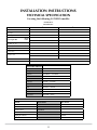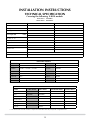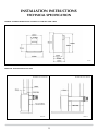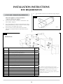
1
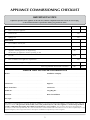
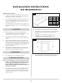
E-Studio & E-box
™
™
Balanced Flue
With upgradable control valve
Instructions for Use,
Installation and Servicing
For use in GB, IE (Great Britain and Eire)
This appliance has been certified for use in countries other than those stated. To install this appliance in these countries, it is essential to obtain the
translated instructions and in some cases the appliance will require modification. Contact Gazco for further information.
IMPORTANT
Do not attempt to burn rubbish on this fire. This appliance must only be operated with the glass window secured firmly in
position. The front casing of this appliance will become hot whilst in operation, it is therefore recommended that a suitable guard
should be used for the protection of young children, the elderly or infirm.
Please read these instructions carefully before installation or use. Keep them in a safe place for future reference and when
servicing the fire.
The commissioning sheet on page 3 must be completed by the Installer.
PR0776 Issue 5 (September 2008)
CONTENTS
Covering the following models:
8692BFCHUC
P8692BFCHUC
8692MCUC
P8692MCUC
8692PBUC
8692PBUC
Appliance commissioning checklist
3
user instructions
4
instaLlation Instructions
11
Technical Specifications
11
Site Requirements
14
Installation
16
Commissioning
23
Servicing Instructions
24
Servicing Requirements
24
Fault Finding
24
How to replace parts
26
Basic spare parts list
31
Service Record
32
2
APPLIANCE COMMISSIONING CHECKLIST
IMPORTaNT NOTICE
Explain the operation of the appliance to the end user, hand the completed instructions to them for safe keeping,
as the information will be required when making any guaranteed claims.
FLUE CHECK
Pass
Fail
1.
Flue is correct for appliance
2.
Flue flow test N/A
3.
Spillage test
N/A
GAS CHECK
1.
Gas soundness & let by test
2.
Standing pressure test
mb
3.
Appliance working pressure (on High Setting)
mb
NB All other gas appliances must be operating on full
4.
Gas rate
5.
Does ventilation meet appliance requirements
6.
Have controls been upgraded (Upgradeable models only)
m3/h
N/A
8455 Standard
YES
NO
8456 Programmable Thermostatic and Timer
YES
NO
DEALER AND INSTALLER INFORMATION
Dealer . . . . . . . . . . . . . . . . . . . . . . . . . . . . . . . . . . . . . . . . . . . . . . . . . . . . . . . . . . . . . . . . . . . . . Installation Company . . . . . . . . . . . . . . . . . . . . . . . . . . . . . . . . . . . . . . . . . . . . . . . . .
. . . . . . . . . . . . . . . . . . . . . . . . . . . . . . . . . . . . . . . . . . . . . . . . . . . . . . . . . . . . . . . . . . . . . . . . . . . . . . . ................................................................................
. . . . . . . . . . . . . . . . . . . . . . . . . . . . . . . . . . . . . . . . . . . . . . . . . . . . . . . . . . . . . . . . . . . . . . . . . . . . . . . ................................................................................
Contact No.. . . . . . . . . . . . . . . . . . . . . . . . . . . . . . . . . . . . . . . . . . . . . . . . . . . . . . . . . . . . . . Engineer . . . . . . . . . . . . . . . . . . . . . . . . . . . . . . . . . . . . . . . . . . . . . . . . . . . . . . . . . . . . . . . . . . . Date of Purchase. . . . . . . . . . . . . . . . . . . . . . . . . . . . . . . . . . . . . . . . . . . . . . . . . . . . . . . Contact No.. . . . . . . . . . . . . . . . . . . . . . . . . . . . . . . . . . . . . . . . . . . . . . . . . . . . . . . . . . . . . . . Model No.. . . . . . . . . . . . . . . . . . . . . . . . . . . . . . . . . . . . . . . . . . . . . . . . . . . . . . . . . . . . . . . . Corgi Reg No.. . . . . . . . . . . . . . . . . . . . . . . . . . . . . . . . . . . . . . . . . . . . . . . . . . . . . . . . . . . . Serial No.. . . . . . . . . . . . . . . . . . . . . . . . . . . . . . . . . . . . . . . . . . . . . . . . . . . . . . . . . . . . . . . . . Date of Installation . . . . . . . . . . . . . . . . . . . . . . . . . . . . . . . . . . . . . . . . . . . . . . . . . . . . Gas Type . . . . . . . . . . . . . . . . . . . . . . . . . . . . . . . . . . . . . . . . . . . . . . . . . . . . . . . . . . . . . . . . . This product is guaranteed for 2 years from the date of installation, as set out in the terms and conditions of sale between Gazco and your
local Gazco dealer. This guarantee will be invalid, to the extent permitted by law, if the above Appliance Commissioning Checklist is
not fully completed by the installer and available for inspection by a Gazco engineer. The guarantee will only be valid during the
second year, to the extent permitted by law, if the annual service recommended in the Instructions for Use has been completed by a Corgi
registered engineer, and a copy of the service visit report is available for inspection by a Gazco engineer.
3
USER INSTRUCTIONS
knob is pointing to pilot
the pilot has not lit,
does.
1. general
. The pilot should now light. If
repeat the procedure until it
• Keep the control knob pressed for 10 seconds and then release it, the pilot should stay alight. If the pilot goes out,
repeat the procedures until it does.
2.3
If the pilot will not light after repeated attempts, contact the
retailer or installer from whom the appliance was
purchased.
• Turn the right-hand control to point to main burner
The fire can now be controlled using the left-hand
control knob.
,
• Turn the left hand control knob to point to low fire the main burner will light on low. The burner can
now be controlled between low and high settings. Turn the
control knob anticlockwise to increase the flame height and
clockwise to decrease the flame height.
1.1
Installation and servicing must only be carried out by a
competent person.
1.2
In all correspondence, please quote the appliance type and
serial number, which can be found on the databadge
adjacent to the control knob.
1.3
Ensure that curtains are not positioned above the fire, and
that there is a 300mm minimum clearance between the
sides of the fire and any curtains.
1.4
This product is guaranteed for 2 years from the date of
installation, as set out in the terms and conditions of sale
between Gazco and your local Gazco dealer. Please consult
with your local Gazco dealer if you have any questions. In
all correspondence always quote the Model Number and
Serial Number.
1.5
Parts of this appliance become hot during normal use. It is
therefore recommended that a suitable fire guard be used
for protection of young children and the infirm.
1.6
If any cracks appear in the glass panel do not use the
appliance until the panel has been replaced.
3.1
To turn the fire off, locate the control valve, turn the lefthand control knob until it points to off ( ). The main burner
will go out leaving the pilot burning.
2. LIGHTING THE APPLIANCE
3.2
To turn the pilot off, locate the control valve, turn the right
hand control knob until it points to off ( ), the pilot will
go out.
2.1
3. TURNING THE APPLIANCE OFF
Locate the control valve on the appliance. There are two
control knobs on the valve, the right hand knob controls the
pilot ignition and the left hand knob controls the main
burner.
4. UPGRADING YOUR FIRE
2.2 If your appliance has already been upgraded to battery
remote control, please refer to the instructions provided
with the upgrade to operate the remote control. The
following instructions will work for either situation.
1
AR0914
• Ensure that the left-hand control knob is pointing to off (
).
• Ensure that the right hand control knob is pointing to
off ( ).
• Press in the right hand control knob and rotate it anticlockwise until a click is heard (keep pressing in) and the
.
4
4.1
Your fire is fitted with a control valve that can easily be
upgraded to battery powered remote control. This upgrade
can be fitted by anyone capable of simple DIY jobs and
requires no special training. This upgrade can be obtained
through your local Gazco stockist.
4.2
STANDARD REMOTE CONTROL This remote control can
control the fire after the pilot has been lit. It can turn the
main burner on and regulate it from low through to high
and back again. It can turn the main burner off leaving the
pilot burning GAZCO PART NUMBER 8455.
4.3
PROGRAMMABLE THERMOSTATIC AND TIMER REMOTE
CONTROL. This remote control can control the gas
appliance after the pilot has been lit. In MANUAL MODE it
can be used to turn the main burner on and manually
regulate it from low through to high and back again. It can
be used to turn the main burner off, leaving the pilot
burning. In AUTO MODE it will automatically regulate the
room temperature to a pre-set temperature. In
USER INSTRUCTIONS
TIMER MODE it will turn the fire on and off according to
pre-set programme and automatically regulate the room
temperature during the two periods. GAZCO PART NO.
8456.
3
CLEANING THE FIRE
ENSURE THE FIRE IS COLD BEFORE PROCEEDING
5.1
• Refer to the separate Frame Instructions to remove the
frame from the fire.
AR1465
AR1423
5A. CLEANING THE E-STUDIO
5.2
• Remove the glass window by unscrewing the 8 screws in
the glass window frame, Diagram 2
5.5
To clean the glass surface, Gazco recommends you use a
ceramic glass product generally sold for cleaning ceramic
hobs.
• Remove the ceramic coals or pebbles and fuel bed and
place on a dry clean surface
• Clean the burner and tray assembly using a vacuum
cleaner with a soft brush attachment
• Ensure all debris is removed from the ports
• Replace the ceramics by referring to section 6B
2
ADVICE ON HANDLING AND DISPOSAL OF FIRE
CERAMICS
AR1996
5.3
To clean the glass surface, Gazco recommends you use a
ceramic glass product generally sold for cleaning ceramic
hobs.
• Remove the granite chippings and place on a dry clean
surface. Do not remove the enamel back panel
• Use a damp cloth and mild non-abrasive cleaner on the
enamel back panel
• Clean the burner and tray assembly using a vacuum
cleaner with a soft brush attachment
• Ensure all debris is removed from the burner ports
• Replace the granite chippings by referring to Section 6A
for E-Studio.
5B. CLEANING THE E-BOX
5.4
• Remove the glass window by loosening the four screws in
the lower retaining bracket
• Remove the four top screws and retaining bracket. The
glass window can now be lifted clear. See diagram 3.
5
The fuel effect and side panels in this appliance are made
from Refractory Ceramic Fibre (RCF), a material which is
commonly used for this application.
Protective clothing is not required when handling these
articles, but we recommend you follow normal hygiene
rules of not smoking, eating or drinking in the work area
and always wash your hands before eating or drinking.
To ensure that the release of RCF fibres are kept to a
minimum, during installation and servicing a HEPA filtered
vacuum is recommended to remove any dust accumulated
in and around the appliance before and after working on it.
When servicing the appliance it is recommended that the
replaced items are not broken up, but are sealed within
heavy duty polythene bags and labelled as RCF waste.
RCF waste is classed as stable, non-reactive hazardous waste
and may be disposed of at a licensed landfill site.
Excessive exposure to these materials may cause temporary
irritation to eyes, skin and respiratory tract; wash hands
thoroughly after handling the material.
USER INSTRUCTIONS
5
6
6A. ARRANGeMENT OF THE
FUEL BED COMPONENTS - E STUDIO
A
ONLY USE THE CORRECT TYPE AND QUANTITY OF GRANITE
CHIPPINGS. Always follow the fuel bed layout as
stated in these instructions. NEVER change the
layout from that shown here.
6.1
AR1997
• Arrange the granite chippings in the areas highlighted in
Diagram 4. Granite chippings should be evenly distributed.
4
• Ensure that no chippings overhang or fill the pilot area,
Arrow B, Diagram 7.
NOTE: CHIPPINGS SHOULD NOT BE PLACED DIRECTLY
IN FRONT OF THE PILOT CROSS LIGHTING FLAME.
57
B
B
AR1997
• Lean the granite chippings against the burner ledges to
disguise the ledges, Diagram 5
5
AR1998
FITTING THE GLASS WINDOW - E-STUDIO
6.2
• Ensure that the fibre glass window seal on the box is
intact
• Replace the one-piece glass window frame, ensuring that
all 8 fixings are tight, Diagram 8.
AR1769
58
• Check that the port area. Arrow A, Diagram 6 is clear of
granite chippings. This can be easily done by gently running
a screwdriver or similar object along this area.
NOTE: IT IS IMPORTANT THE GRANITE CHIPPINGS DO
NOT COVER THE PORT AREA IN BETWEEN THE
BURNER LEDGES.
AR1996
6
NEVER OPERATE THE FIRE WHEN THE GLASS PANEL IS
REMOVED OR BROKEN
USER INSTRUCTIONS
• Refer to the separate Frame Instructions to replace the
frame on the fire
11
6B. ARRANGeMENT OF THE
FUEL BED COMPONENTS - E-BOX
NOTE: CERAMIC PARTS ARE FRAGILE. HANDLE WITH CARE
ONLY USE THE CORRECT TYPE AND QUANTITY OF CERAMIC
COMPONENTS
6.3 AR1362
•Place the rear panel against the rear of the box resting on
the shelf
•Slide one of the side panels into the box ensuring it
touches the rear panel
• Gently ease the front edge of the side panel behind the
flange so it lies flat against the wall of the box
• Repeat with the second side panel, Diagram 9
• Place the front coal centrally in the channel at the front
of the tray. The relationship between the front coal and the
flame baffle is shown, Diagram 12.
12
9
AR1363
AR1359
6.5
AR1360
• Locate the top panel on top of the sides and rear by lifting it up and forward inside the box
• Slide it backwards and down behind the side panels to rest on the rear panel, Diagram 10
There are three sizes of coal used. Small x3, medium x4
and large x1. For identification, Diagram 13.
13
5
10
LARGE
MEDIUM
SMALL
AR1379
AR1426
COAL LAYOUT
6.4
• Position the flame baffle centrally on the tray and ensure
the stepped lower edge engages against the rear edge of the
burner skin, Diagram 11
7
• Place the single large coal in the central dent of the front
coal resting against the flame baffle, Diagram 14.
USER INSTRUCTIONS
14
• Place the last two small coals to the left and right-hand
side of the bed in the two spaces, Diagram 18.
18
AR1364
• Place 2 medium-size coals either side of the first large
coal, in the recess between the flame baffle and the front
coal, Diagram 15.
AR1368
15
PEBBLE LAYOUT
• Position the pebble flame baffle centrally on the tray and
ensure the stepped lower edge engages against the rear
edge of the burner skin, Diagram 19.
19
AR1365
•
Place another two medium size coals behind the first three
coals and against the flame baffle, Diagram 16.
AR1406
16
• Place the front pebble piece centrally in the channel at
the front of the tray. See Diagram 20.
20
AR1366
• Place a small coal directly behind the first large coal, and
in between the centre of the last two medium coals resting
on the flame baffle, Diagram 17.
AR1407
17
6.6
AR1367
8
There are 10 loose pebbles in the set supplied. Each pebble
is individually marked. The quantity of each type is shown
below.
A1 x 3
A4 x 1
A2 x 1
A5 x 1
A3 x 3
A6 x1
• Place the four pebbles as identified resting between the
front ceramic and the flame baffle as shown in diagram 21.
USER INSTRUCTIONS
21
FITTING THE GLASS WINDOW - E-BOX
A4
A5
A3
AR1408
A6
6.9
• Ensure that the fibre glass window seal on the box is
intact, then lower the glass window into the lower retaining
bracket.
• Hold the window and position the upper retaining
bracket
• Secure using the 4 screws.
• Tighten the bottom and top screws to retain the window,
Diagram 24.
• Place the next four pebbles as shown resting between the
flame baffle and the first row of pebbles, Diagram 22.
24
22
AR1465
AR1423
A1
A1
A2
AR1409
• Place the remaining two A3 pebbles as shown in
Diagram 23.
• Refer to the separate Frame Instructions to replace the
frame on the fire.
NEVER OPERATE THE APPLIANCE WHEN THE GLASS
PANEL IS REMOVED OR BROKEN.
7. flame failure device
23
7.1
This is a safety feature incorporated on this appliance which
automatically switches off the gas supply if the pilot goes
out and fails to heat the thermocouple.
8. running in
A3
A3
8.1
AR1410
6.7
The coals/pebbles should evenly cover the whole bed with
the gaps between them kept equal. This will maximise the
performance of the product.
6.8
ENSURE THAT THE COALS/PEBBLES ARE POSITIONED
AS ABOVE. ONLY USE THE CORRECT AMOUNT OF
COALS/PEBBLES AS SPECIFIED IN THE DIAGRAMS.
The surface coating on the coals used in your GAZCO fire
will "burn off" during the first few hours of use producing a
harmless and temporary odour. This will disappear after a
short period of use. If the odour persists, ask your installer
for advice.
9. servicing
9.1
9
The fire must be serviced every 12 months by a qualified
Gas Engineer. In all correspondence always quote the
Model number and the Serial number which may be found
on the databadge.
USER INSTRUCTIONS
10. ventilation
10.1 This appliance requires no additional ventilation.
11. installation details
11.1 To assist in any future correspondence, your installer should
have completed the commissioning sheet at the front of this
book, this records the essential installation details of the
appliance. In all correspondence always quote the Model
number and Serial number.
12. HOT SURFACES
12.1 Parts of this appliance become hot during normal use. It is
therefore recommended that a suitable fire guard be used
for protection of young children and the infirm. Indeed, all
parts of the appliance should be treated as a 'working
surface' except for the control access panel.
10
INSTALLATION INSTRUCTIONS
TECHNICAL SPECIFICATION
Covering the following E-STUDIO models:
8692BFCHUC
P8692BFCHUC
I2H
I3P
Natural
Propane
G20
G31
Working Pressure
20mbar
37mbar
HIGH
Gross
Input kW
LOW
4.3kW
3.75kW
2.5kW
2.3kW
Gas Rate m3/hr
0.401
0.138
Efficiency Class
2
2
NOx Class
4
4
158
170R
8mm x 15mm
23mm x 15mm
GAS CATEGORY
Gas Type
Injector Size
Aeration Size
23mm x 15mm
Flue Outlet Size
100mmø / 152mmø
8mm
Gas Inlet
APPLICABLE FRONTS
FRONT
PART NUMBER
Designio
8272BFMA + 8272BFIR + 8272BFGP
Progress
8253BFMA + 8253BFIR
Dimension
8680MB
Steel
8695GP + 8695IR
Evolution
8258BS + 8258MB
Arts
8282MB + 8282HP + 8282P + 8282PBR
Steel
8695GP + 8695IR
Futura
8687BK
Fusion
8699GP + 8699IR
Winchester
8697MB + 8697P
APPLICABLE FRAME & FRONT COMBINATIONS
FINISH
ARTS FRAME
ARTS FRONT
Black
8283BFMB
8282MB
Brass
8283BFPBR
8282PBR
Brushed Steel
8283BFBS
Polished Steel
8283BFP
Highlight Polished
8282HP
Chrome
8282P
11
INSTALLATION INSTRUCTIONS
TECHNICAL SPECIFICATION
Covering the following E-BOX models:
8692 mcuc 8692PBuc
P8692 mcuc P8692PBUC
I2H
I3P
Natural
Propane
G20
G31
Working Pressure
20mbar
37mbar
HIGH
Gross Input kW
LOW
4.1kW
4.1kW
2.3kW
2.5kW
Gas Rate m3/hr
0.390
0.154
Efficiency Class
1
1
NOx Class
3
3
260
104
12mm x 15mm
6mm x 15mm
GAS CATEGORY
Gas Type
Injector Size
Aeration Size
23mm x 15mm
Flue Outlet Size
100mmø / 152mmø
8mm
Gas Inlet
APPLICABLE FRONTS
FRONT
PART NUMBER
FRONT
PART NUMBER
Designio
8272MA + 8272GP + 8272IR
Stockton
8696
Evolution
8258BS +8258MB + 8258BS
Yeoman
YM98906
Infinity
8256BS
Holyrood
8693MB + 8693PBB + 8693HP
Progress
8253MA + 8253IR
Spanish
8694MB + 8694PBB + 8694HP
Richmond
8679
Futura
8687BK
Dimension
8680MB
Fusion
8699GP + 8699IR
Arts
8282MB + 8282HP + 8282P + 8282PBR
Winchester
8697MB + 8697P
APPLICABLE FRAME & FRONT COMBINATIONS
FINISH
**ARTS FRAME
ARTS FRONT
HOLYROOD FRONT
SPANISH FRONT
Black
8283MB
8282MB
8693MB
8694MB
Brass
8283PBR
8282PBR
8693PBB
8694PBB
8693HP
8694HP
Black/Brass
Brushed Steel
8283BS
Polished Steel
8283P
Highlight Polished
8282HP
Chrome
8282P
** The Arts Frame must be used in conjunction with either the Arts, Holyrood or Spanish Front.
12
INSTALLATION INSTRUCTIONS
TECHNICAL SPECIFICATION
OVERALL EXTERNAL DIMENSIONS FOR BOTH E-STRUDIO AND E-BOX
AR1427
MININUM AND MAXIMUM FLUE SIZE
MINIMUM FLUE LENGTH
MAXIMUM FLUE LENGTH
AR1429
AR1428
13
INSTALLATION INSTRUCTIONS
SITE REQUIREMENTS
1.4
1. Flue and Chimney Requirements
NOTE: This appliance can only be installed in
conjunction with the flue supplied.
1.1
The flue must be sited in accordance with BS5440: Part 1
(latest edition), Diagram 1.
1.2
Any terminal which is less than 2 metres above any access
(level ground, balcony or above a flat roof to which people
have access) is to be fitted with a guard.
1.3
The flue must be securely fixed and fire precautions
followed in accordance with local and national codes of
practice.
The horizontal terminal can be reduced in length, Diagram
2.
2
AR0630
1
UK Dimensions
Dimension
Terminal Position
Minimum
Distance
(mm)
A*
Directly below an opening, air brick, opening widows etc
300 mm
B*
Above an opening, air brick, opening windows etc.
300 mm
C*
Horizontal to an opening, air brick, opening windows etc.
300 mm
D
Below gutters, soil pipes or drain pipes
300 mm
E
Below eaves
300 mm
F
Below balconies or car port roof
600 mm
G
From a vertical drain pipe or soil pipe
300 mm
H
From an internal or external corner
600 mm
I
Above ground, roof or balcony level
300 mm
J
From a surface facing the terminal (or boundary)
600 mm
K
From a terminal facing the terminal
600 mm
L
From an opening in the car port (e.g. door, window) into dwelling
1200 mm
M
Vertically from a terminal on the same wall
1500 mm
N
Horizontally from a terminal on the same wall
300 mm
O
From the wall in which the terminal is mounted
N/A
P
From a vertical structure on the roof
N/A
Q
Above intersection with roof
N/A
14
* In addition, the terminal should not be nearer than
300mm to an opening in the building fabric formed for the
purpose of accommodating a built-in element such as a
window frame.
H The reference to external corners does not apply to
building protrusions not exceeding 450mm, such as disused
chimneys on external walls.
INSTALLATION INSTRUCTIONS
SITE REQUIREMENTS
TIMBER FRAMED BUILDINGS
4
A
1.5 It will be necessary to provide additional clearance when
the flue passes through a wall containing any combustible
materials so as to prevent a fire hazard.
B
1.6 The hole through which the flue will pass, must have a steel
sleeve which is positioned so that an air gap of at least
25mm is maintained between the outer surface of the flue,
and any part of the sleeve.
C
E
1.7 For further guidance on the installation of gas appliances in
timber framed buildings, contact your local buildings control
authority.
2.3
Factory-sheathed/wrapped soft copper tubing with small
ridges which allow pipe movement are considered to be a
suitable alternative to a pipe sleeve, when recessing the unit
into a cavity wall the gas supply is best fed through the wall
from the outside. Soft soldered joints can only be used
outside the appliance.
2.4
This appliance is supplied complete with a factory fitted
isolation device incorporated into the inlet connection. No
further isolation device is therefore required.
560 mm
575 mm
237 mm
-
D
300 mm
-
E
420 mm
-
F
12 mm
-
The minimum opening dimensions are shown, Diagram 4.
4.3
This appliance can only be installed on an outside wall with
suitable clearances for the flue terminal and guard (if
required).
4.4
This appliance is not suitable for installation into a
combustible wall. All combustible material must be
removed from the area shown, Diagram 5.
5
720
150
4.5
This appliance requires no additional ventilation.
4. Appliance location
NOTE: It is recommended you construct the back panel of the
fireplace from natural materials cut into three or more
sections to prevent cracking. Resin-based materials may
not be suitable. This appliance is an effective heat
producer and attention must be paid to the construction
and finish of the fireplace.
4.1
B
C
4.2
3. ventilation
3.1
450 mm
860
Ensure that the gas supply is capable of delivering the
required amount of gas, and is in accordance with the rules
in force.
MAX
420 mm
300
2.2
MIN
A
AR0184
560
Before installation, ensure that the local distribution
conditions (identification of the gas type and pressure) and
the adjustment of the appliance are compatible.
DIMENSIONS
F
2. GAS SUPPLY
2.1
D
This appliance must stand on a non combustible hearth that
is at least 12mm thick. If the fire is greater than 50mm
above the floor, then no hearth is required, although due
consideration should be given to how the heat may affect
the floor material.
15
420
AR1227
The maximum depth of combustible shelf is 150mm at a
minimum height of 300mm above the fireplace opening.
INSTALLATION INSTRUCTIONS
INSTALLATION
1. UNPACKING
1.1
• Remove the appliance from its packaging, and check that
it is complete and undamaged
• Put the loose ceramic parts to one side so that they are
not damaged during installation.
4. INSTALLATION OF THE GAS SUPPLY
E-STUDIO BF
NAT GAS @ 20MB
PROPANE @ 37mb
8692BFCHUC
P8692BFCHUC
2. CONTROL UPGRADE
E-BOX BF
2.1
2.2
2.3
Your fire is fitted with a control valve that can be easily
upgraded to battery powered remote control. This upgrade
can be fitted by anyone capable of simple DIY jobs and
requires no special training. This upgrade can be obtained
through your local Gazco stockist.
NAT GAS @ 20MB
PROPANE @ 37mb
8692MCUC
P8692MCUC
8692PBUC
P8692PBUC
STANDARD REMOTE CONTROL This remote control can
control the fire after the pilot has been lit. It can turn the
main burner on and regulate it from low through to high
and back again. It can turn the main burner off leaving the
pilot burning. GAZCO PART NUMBER 8455.
PROGRAMMABLE THERMOSTATIC AND TIMER REMOTE
CONTROL. This remote control can control the gas
appliance after the pilot has been lit. In MANUAL MODE it
can be used to turn the main burner on and manually
regulate it from low through to high and back again. It can
be used to turn the main burner off, leaving the pilot
burning. In AUTO MODE it will automatically regulate the
room temperature to a pre-set temperature. In
TIMER MODE it will turn the fire on and off according to
pre-set programme and automatically regulate the room
temperature during the two periods. GAZCO PART NO.
8456.
TO CHANGE FROM ONE GAS TYPE TO ANOTHER A COMPLETE ENGINE ASSEMBLY WILL BE REQUIRED. SEE SECTION 12 REPLACING PARTS.
4.1
Before installation, ensure that the local distribution
conditions (identification of the type of gas and pressure)
and the adjustment of the appliance are compatible. See
table above.
4.2
The position of the gas inlet pipe is shown, Diagram 3.
3
3. SAFETY PRECAUTIONS
AR1467
3.1
This appliance must be installed in accordance with the
rules in force, and used only in a sufficiently ventilated
space. Please read all instructions before installation and use
of this appliance.
4.3
All supply pipes must be purged of any debris that may
have entered, prior to connection to the appliance.
3.2
These instructions must be left intact with the user.
4.4
3.3
Do not attempt to burn rubbish on this appliance.
The gas supply enters through the silicone panel located on
the rear of the outer box. This will need to be slit with a
sharp knife prior to passing the supply pipe through.
3.4
In your own interest, and those of safety, this appliance
must be installed by a competent person in accordance
with local and national codes of practice. Failure to install
the appliance correctly could lead to prosecution.
3.5
Keep all plastic bags away from young children.
5. PREPARING THE APPLIANCE
5.1
16
Remove the backing from the self-adhesive silicone sealing
strip and apply to the rear flange of the firebox ensuring that
the strip is positioned as close to the outer edge as is
practically possible, Diagram 1, arrow A.
INSTALLATION INSTRUCTIONS
INSTALLATION
1
3
A
B
AR1436
AR1435
5.2
Gas pipe entry must come through the rear right-hand side
of the box. The rubber seal must be cut using a sharp knife
to allow the isolating elbow to pass through it.
• Ensure the rubber is not damaged when doing this,
Diagram 1, arrow B.
A means of isolation is provided with the appliance. This
must be fitted to the supply pipe prior to installing the
firebox.
The appliance can either be recessed into an inner leaf of
the wall. A 75mm rebate surround must be used with this
method. Or it can be installed in front of the wall in
conjunction with a fire surround constructed of a studwork
frame, Diagram 2 for options.
6.2
A 152mm (6’) diameter hole is required to install the flue.
This can be achieved by either:
a) Core drill
b) Hammer and chisel.
It is advisable to drill small holes around the circumference
when using method b. Make good both ends of the hole.
2
6.3
It will now be necessary to construct a studwork frame to
house the appliance. The minimum depth of the aperture
must be 237mm. This includes an air gap of 5mm behind
the appliance. The sides must be lined with noncombustible material for the full depth of the aperture.
6.4
Combustible parts of the studwork frame must not be any
closer than the minimum dimensions shown in Diagram 4.
These dimensions need to be maintained even if the frame
work is protected by non combustible material.
6.5
Do not pack the void around or above the appliance with
insulation material such as mineral wool.
4
AR1428
AR1429
AR1430
6. non recessed installation
6.1
• Mark the position of the flue on the inner wall by
measuring from the top of the finished hearth level,
Diagram 3.
AR1431
17
INSTALLATION INSTRUCTIONS
INSTALLATION
6.6
The void into which the appliance is fitted must be
ventilated to prevent a build up of heat. If the void is sealed
then it will be necessary to fit vents at both low and high
levels of approximately 50cm2. These vents should take cold
air from the room and return warm air back into the room.
8. Installation of the appliance
8.1
The flue can be cut to length, measure the thickness of the
wall the flue is passing through, then deduct 12mm. This is
the length required when measuring from the line on the
flue label. This must be level with the outside wall face
when fitted, Diagram 7.
This method of installation requires structural alteration to
the intended location. A suitable supporting lintel must be
installed to maintain the structural integrity of the
surrounding blockwork.
7
7. recessed installation
7.1
Mark the position of the lintel so that it sits centrally over
the intended installation. Remove the blockwork and install
the lintel using mortar to ensure a strong bond with the
surrounding wall, Diagram 5.
AR0630
5
8.2
There is a cardboard fitment in the terminal. This is to
support the flue whilst it is cut to length. REMOVE THE
REMAINDER OF THE CARDBOARD AFTER CUTTING TO
SIZE
• Remove the compression elbow from the appliance and
connect it to the gas supply pipe, taking note of its
orientation
• Attach the flue to the appliance and seal using the
aluminium tape provided
8.3
As the appliance is positioned into the opening of the
enclosure, pass the flue pipe through the hole in the wall. It
will be necessary to pass the supply pipe with the elbow
through the silicone panel on the right hand side of the box.
• Secure the appliance in place using screws and rawl
plugs provided
• PURGE THE SUPPLY PIPE. This is essential to expel any
debris that may block the gas controls. Connect the elbow
to the appliance inlet pipe.
8.4
• Connect a suitable pressure gauge to the test point
located on the inlet elbow and turn the gas on
• Light the appliance and check for leaks
• Turn the appliance to maximum and check that the
supply pressure is as stated on the databadge
• Turn the gas supply off and replace the test point screw
• Turn the gas on and check the test point for leaks
AR0705
7.2
With the lintel in position mark the width of the aperture
and remove the blockwork. If there is loose cavity insulation
this must be retained. This can be achieved by using
Rockwool or similar, Diagram 5.
7.3
Mark the position of the flue on the wall by measuring from
the top of the finished hearth level, Diagram 6.
6
AR1436b
7.4
A 152mm (6’) diameter hole is required to install the flue.
This can be achieved by either:
a) Core drill
b) Hammer and chisel
It is advisable to drill small holes around the circumference
when using method b. Make good both ends of the hole.
18
INSTALLATION INSTRUCTIONS
INSTALLATION
5
10
9A. ARRANGeMENT OF THE
FUEL BED COMPONENTS - E STUDIO
A
ONLY USE THE CORRECT TYPE AND QUANTITY OF GRANITE
CHIPPINGS. Always follow the fuel bed layout as
stated in these instructions. NEVER change the
layout from that shown here.
9.1
• Arrange the granite chippings in the areas highlighted in
Diagram 8. Granite chippings should be evenly distributed.
AR1997
8
• Ensure that no chippings over-hang or fill the pilot area,
Arrow B, Diagram 11.
NOTE: CHIPPINGS SHOULD NOT BE PLACED DIRECTLY
IN FRONT OF THE PILOT CROSS LIGHTING FLAME.
5
11
B
B
AR1997
• Lean the granite chippings against the burner ledges to
disguise the ledges, Diagram 9
59
AR1998
FITTING THE GLASS WINDOW - E-STUDIO
AR1769
• Check that the port area. Arrow A, , Diagram 10 is clear
of granite chippings. This can be easily done by gently
running a screwdriver or similar object along this area.
NOTE: IT IS IMPORTANT THE GRANITE CHIPPINGS DO
NOT COVER THE PORT AREA IN BETWEEN THE
BURNER LEDGES.
• Ensure that the fibre glass window seal on the box is
intact.
• Replace the one-piece glass window frame ensuring that
all 8 fixings are tight, Diagram 12.
5
12
AR1769
19
NEVER OPERATE THE FIRE WHEN THE GLASS PANEL IS
REMOVED OR BROKEN
• Refer to the separate Frame Instructions to replace the
frame on the fire
INSTALLATION INSTRUCTIONS
INSTALLATION
15
9B. ARRANGeMENT OF THE
FUEL BED COMPONENTS - E-BOX
NOTE: CERAMIC PARTS ARE FRAGILE. HANDLE WITH CARE
ONLY USE THE CORRECT TYPE AND QUANTITY OF CERAMIC
COMPONENTS
9.2 • Place the rear panel against the rear of the box resting on the shelf.
•Slide one of the side panels into the box ensuring it touches the rear panel.
• Gently ease the front edge of the side panel behind the
flange so it lies flat against the wall of the box.
• Repeat with the second side panel, Diagram 13
AR1362
13
• Place the front coal centrally in the channel at the front
of the tray. The relationship between the front coal and the
flame baffle is shown, Diagram 16.
16
AR1363
AR1359
AR1360
6.5
• Locate the top panel on top of the sides and rear by lifting it up and forward inside the box.
• Slide it backwards and down behind the side panels to rest on the rear panel, Diagram 14.
There are three sizes of coal used. Small x3, medium x4
and large x1. For identification, Diagram 17.
17
5
14
LARGE
MEDIUM
SMALL
AR1379
AR1426
COAL LAYOUT
9.3
• Position the flame baffle centrally on the tray and ensure
the stepped lower edge engages against the rear edge of the
burner skin, Diagram 15
20
• Place the single large coal in the central dent of the front
coal resting against the flame baffle, Diagram 18.
INSTALLATION INSTRUCTIONS
INSTALLATION
21
18
AR1367
AR1364
• Place the last two small coals to the left and right-hand
side of the bed in the two spaces, Diagram 22
• Place 2 medium size coals either side of the first large
coal, in the recess of the front coal between the flame baffle
and the front coal, Diagram 19.
22
19
AR1368
PEBBLE LAYOUT
AR1365
• Place another two medium size coals behind the first
three coals and against the flame baffle, Diagram 20.
• Position the pebble flame baffle centrally on the tray and
ensure the stepped lower edge engages against the rear
edge of the burner skin, Diagram 23
23
20
AR1406
AR1366
• Place a small coal directly behind the first large coal, and
in between the centre of the last two medium coals resting
on the flame baffle, Diagram 21
21
• Place the front pebble piece centrally in the channel at
the front of the tray. See Diagram 24
INSTALLATION INSTRUCTIONS
INSTALLATION
27
24
A3
A3
AR1407
AR1410
9.4
There are 10 loose pebbles in the set supplied. Each pebble
is individually marked. The quantity of each type is shown
below.
A1 x 3
A4 x 1
A2 x 1
A5 x 1
A3 x 3
A6 x1
9.5
The coals/pebbles should evenly cover the whole bed with
the gaps between them kept equal. This will maximise the
performance of the product.
9.6
ENSURE THAT THE COALS/PEBBLES ARE POSITIONED
AS ABOVE. ONLY USE THE CORRECT AMOUNT OF
COALS/PEBBLES AS SPECIFIED IN THE DIAGRAMS.
• Place the four pebbles as shown resting between the
front ceramic and the flame baffle, Diagram 25
FITTING THE GLASS WINDOW - E-BOX
25
A4
A5
A3
AR1408
A6
9.7
• Ensure that the fibre glass window seal on the box is
intact, then lower the glass window into the lower retaining
bracket.
• Hold the window and position the upper retaining
bracket
• Secure using the 4 screws.
• Tighten the bottom and top screws to retain the window,
Diagram 28.
28
• Place the next four pebbles as identified resting between
the flame baffle and the first row of pebbles as shown in
Diagram 26
26
AR1465
A1
A1
•
A2
• Refer to the separate Frame Instructions to replace the
frame on the fire
NEVER OPERATE THE APPLIANCE WHEN THE GLASS
PANEL IS REMOVED OR BROKEN.
AR1409
Place the remaining two A3 pebbles as shown in Diagram
27.
22
AR1423
INSTALLATION INSTRUCTIONS
INSTALLATION / COMMISSIONING
10. LIGHTING THE APPLIANCE
11. commissioning
10.1 • Locate the control valve on the fire. There are two control knobs on the valve, the right-hand knob controls the
pilot ignition and the left hand knob controls the main
burner.
10.2 If your fire has already been upgraded to battery remote
control, please refer to the instructions provided with the
upgrade to operate the remote control. The
following instructions will work for either situation.
2
AR0914
• Ensure that the left-hand control knob is pointing to off (
).
• Ensure that the right hand control knob is pointing to
off ( ).
• Press in the right hand control knob and rotate it anticlockwise until a click is heard (keep pressing in) and the
. The pilot should now light. If
knob is pointing to pilot
the pilot has not lit,
repeat the procedure until it
does.
• Keep the control knob pressed for 10 seconds and then release it, the pilot should stay alight. If the pilot goes out,
repeat the procedures until it does.
• Turn the right-hand control to point to main burner
The fire can now be controlled using the left-hand
control knob.
,
• Turn the left hand control knob to point to low fire the main burner will light on low. The burner can
now be controlled between low and high settings. Turn the
control knob anticlockwise increase the flame height and
clockwise to decrease the flame height.
.
THE YELLOW FLAMES WILL APPEAR WHEN THE FIRE HAS GAINED SUFFICIENT HEAT - TYPICALLY 10 TO 20 MINUTES.
23
11.1
Check all ceramics, doors etc.
11.2
Check flame picture
11.3
Check gas pressure
SERVICING INSTRUCTIONS
SERVICING / FAULT FINDING CHARTS
1. SERVICING REQUIREMENTS
SYSTEM OK
GO TO THE NEXT
CHART - IGNITION
FUNCTIONAL CHECK 2
There is a blockage in the system, check the inlet test point,
the mag seating and valve.
Purge the gas pipes and retry.
No
Has the system got
any air in it?
Yes
Yes
Yes
Is the gas pressure correct?
No
Correct and
retry.
Check alignment of pilot
burner head, change the
ignition lead.
See Replacing Parts, section 7.
24
Check isolation tap and
gas meter, retry.
No
Is the gas turned on to the
appliance?
No
Will the pilot light
with a match?
Yes
Yes
Is the control being
operated correctly?
No
Consult User
Instructions and retry.
No
Does the pilot light?
Yes
Operate the valve.
Is there a spark?
No
Ensure there is no debris around the pilot assembly,
(e.g. soot, etc.) which could short the spark, clean the area.
PILOT WILL NOT LIGHT
IGNITION FUNCTIONAL CHECK 1
Yes
This appliance must be serviced at least once a year by a
competent person.
All tests must be serviced by best practice as described by the
current CORGI recommendations.
1.1 Before any tests are undertaken on the appliance, conduct
a gas soundness test for the property to ensure that there
are no gas leaks prior to starting work.
1.2 Before any tests are undertaken on the appliance it is also
recommended to fully check the operation of the appliance.
1.3 Special checks
1.3.1 Check the flue terminal position complies with the
requirements, and that the terminal is not obstructed.
1.3.2 Clean away any debris under the burner.
1.3.3 Check the condition of ceramics, pilot and burner
cover gasket.
1.4 Correct any faults found during the initial tests and then
re-commission the appliance conducting the usual safety
checks.
1.5 Advise the customer of any remedial action taken.
25
Replace the valve.
No
Is the electrode wire
detachable from the piezo
in the valve?
No
Replace the electrode.
Yes
Correct and retry.
Reset the electrode gap, retry.
Is the valve being
operated correctly?
Yes
Remove the electrode lead from
the piezo. Place a small insulated
screwdriver close to the piezo
connection and operate the
valve. Does a spark jump from
the piezo to the valve body?
Check for defective or
damaged control knob spindle
or cam operation. Check for
correct location of piezo
components. Correct and retry.
Replace the electrode
lead and retry.
Yes
Yes
No
No
Remove the electrode lead
from electrode with insulated
pliers. Hold the tip 3.5mm from the
pilot pipework, is there a spark
when the valve ‘clicks’?
No
Has ignition lead
become detached or is
connection poor?
Yes
Is the gap between
electrode and
thermocouple 4.0mm?
Yes
From Ignition Fault
Finding Chart 1
Consult the users
instructions, retry. Ensure there is no debris around the pilot assembly,
(e.g. soot etc.) which could short the spark, clean the area.
NO SPARK
IGNITION FUNCTIONAL CHECK 2
Yes
Change the
pilot injector.
No
Is the pilot flame of the
correct length?
Yes
With the pilot
running is the gas
pressure as stated on
the databadge?
No
Will pilot
stay alight?
Is thermocouple
connection good
in back of valve?
SYSTEM OK
Change mag
unit.
No
Will pilot
stay alight?
No
Yes
Replace thermocouple.
No
No
Yes
No
Problem is with the
pipework or
fittings which lead
to the fire. Correct
and retry.
Yes
No
Yes
Run for 3 mins, turn
off, time interval until
mag unit shuts with a
click. Is this greater
than 7 seconds?
Tighten the
connection and retry.
Run for 3 mins,
turn off, time interval
until mag unit shuts
with a click. Is this
greater than 7
seconds?
Yes
With the fire running
on full is the gas at
the pressure stated
on the databadge?
Light the pilot and keep the control knob pushed in
at least 10 seconds before letting go.
Ensure there is no debris around the pilot assembly,
(e.g. soot etc.)
PILOT WILL NOT STAY LIT OR FIRE GOES OUT IN USE
FLAME FAILURE FUNCTIONAL CHECK 3
Yes
SERVICING INSTRUCTIONS
FAULT FINDING CHARTS
SERVICING INSTRUCTIONS
REPLACING PARTS
52
1. GENERAL
1.1
All principal components can be replaced without removing
the appliance from its installation, although it is essential
that the gas supply to the appliance is turned off at the
isolation device before proceeding further.
1.2
Before replacing some of the components it will first be
necessary to remove the burner assembly from the
appliance by following the instructions below.
1.3
If for any reason the flue has to be removed from the
appliance, the seal must be replaced in the inner spigot.
AR1999
2. REMOVING THE BURNER UNIT
• Carefully remove the enamel back panel by rotating it
out of the fire box, Diagram 3
53
Ensure the appliance is cold before proceeding
2.1
• Turn the gas supply off at the isolation device. Then
disconnect the supply pipe.
• Remove the frame from the appliance by referring to the
separate frame instructions supplied.
2A. E-STUDIO
AR1880b
• Remove the one-piece glass window frame by removing
the eight fixing screws, Diagram 1
51
TAKE EXTREME CARE WHILST REMOVING THESE
PANELS NOT TO SCRATCH OR CHIP THE PANEL ON
THE SIDES OF THE FIREBOX
• Unscrew the 3 fixings in the rear liner support, Diagram
4, and lift this part out of the appliance.
54
AR1996
• Remove the granite chippings from the appliance.
• Remove the top inner baffle by unscrewing the two fixing
screws located on the front edge of the top plate, Diagram2
AR2000
26
• Remove the left and right-hand burner baffle brackets by
unscrewing the two fixings located on the burner tray top,
Diagram 5
SERVICING INSTRUCTIONS
REPLACING PARTS
55
• Remove the ceramic coals and fuel bed and place on a
dry clean surface
• Remove the ceramic panels from inside the appliance
• Remove the two screws securing the front U channel on
the burner assembly. This is to gain access to the burner
retaining screws, Diagram 8.
8
AR2001
• Remove the 11 screws that fix the burner assembly into
the appliance, Diagram 6. The burner assembly can now
be removed by lifting it up and out of the appliance.
56
AR1432
2.14 • Remove the 11 screws in the burner tray securing the
burner assembly to the appliance. The burner assembly can
now be removed by lifting it up and out of the appliance,
Diagram 9.
9
AR1980
2B. E-BOX
• Remove the glass window by loosening the four screws in
the lower retaining bracket then remove the four top screws
and retaining bracket. The glass window can now be lifted
clear, Diagram 7
AR1433
3. Pilot unit
7
AR1465
The pilot unit assembly consists of three components which
can be individually changed, these are:1) Pilot Injector
2) Electrode
3) Thermocouple
Note: On the E-Box, access is provided for the removal of the
pilot without removing the engine assembly. It is easier,
however, to change the pilot by removing the whole
assembly.
AR1423
27
SERVICING INSTRUCTIONS
REPLACING PARTS
4A. Pilot injector - E-STUDIO
4.1
5. ELECTRODE
• Undo the pilot pipe from the bulkhead fitting and from
the underside of the pilot unit, Diagram 10
5.1
5
10
• Pull the ignition lead from the electrode and undo the
retaining nut, Diagram 12
12
AR2002
• Remove the pipe and the injector drops out from the
pilot unit. Take care not to loose or damage the injector.
4.2
To replace the injector:
• Reverse the above procedure
• Check for gas leaks.
AR1349
• Replace with new electrode. Do not over tighten the nut
as this could break the new component
• Replace the ignition lead
6. Thermocouple
4B. Pilot injector - E-BOX
4.3
6.1
• Undo the pilot pipe from the valve and from the under
side of the pilot unit, Diagram 11
• Disconnect the thermocouple from the gas valve,
Diagram 13
13
11
A
AR1434
AR1434
• Remove the pipe and the injector drops out from the
pilot unit. Take care not to loose or damage the injector.
4.4
To replace the injector:
• Reverse the above procedure
• Check for gas leaks
• Undo the thermocouple nut in the pilot unit by half a
turn. This will release the thermocouple.
For E-Studio
28
6.2
• Remove the sealing plate, Diagram 14, by removing the
pozi head screw.
NOTE: The sealing plate needs to be re-sealed after the
new thermocouple is fitted.
SERVICING INSTRUCTIONS
REPLACING PARTS
5
14
16
AR2003
AR0916
WHEN REPLACING WITH A NEW THERMOCOUPLE
TAKE CARE TO BEND THE NEW COMPONENT TO THE
EXACT SHAPE OF THE ORIGINAL ONE
• Disconnect the ignition lead from the valve and
electrode.
6.3
When replacing the thermocouple into the pilot unit ensure
the component is pushed fully into the hole. There is a stop
on the thermocouple to set the height.
(For E-Studio, the sealing plate needs also to be removed,
Diagram 14)
• Lock the retaining nut just enough to grip the
thermocouple
• Replace with a new ignition lead following the same
route as the old one.
(For E-Studio, replace the sealing plate and re-seal with
relevant sealant).
•Replace the valve cover check the operation of the new
ignition lead.
7.3
• Refit the burner unit
7. IGNITION LEad
7.1
• Remove the burner unit. Refer to section 2
• Undo the single screw that secures the left hand side of
the control cover, Diagram 15.
7.4 • Replace the fire frame
8. piezo
15
8.1
The piezo assembly used on this appliance is not
serviceable and is unlikely to fail. If a new piezo is required
it will be necessary to change the gas valve, refer to section
9.
9. gas valve
AR0915
9.1
• Remove the thermocouple from the valve, Diagram 17,
Arrow A.
7.2 To release the right hand side of the control cover:
• Insert the narrow blade screwdriver into the slot shown
in Diagram 16
• Undo the pilot pipe from the gas valve, Diagram 17,
Arrow B.
• Lever it gently and pull from the right hand side at the
same time. The cover will now come off, there is a small
cylindrical metal spacer inside the cover. This must be kept
and replaced on the fixing screw during re-assembly.
• Undo the inlet pipe from the valve, Diagram 17, Arrow C.
• Undo the feed pipe from the valve, Diagram 17, Arrow
D.
• Disconnect the ignition lead from the pilot unit. (For
E-Studio, the sealing plate needs to be removed, Diagram
14)
29
SERVICING INSTRUCTIONS
REPLACING PARTS
• Undo the two screws securing the valve to the bracket,
Diagram 17, Arrow E. The valve can now be removed.
19
17
E
AR1433
D C A
B
AR1434
10. Mag unit
• Rotate the injector until it is fully removed
• Replace with the correct replacement injector. When ordering, always state the model, gas type and serial
number.
• Reassemble and turn the gas supply on, check for any
leaks
10.1 Undo the thermocouple nut, Diagram 18, Arrow A.
12. changing between gas types
18
The following parts must be changed when converting an appliance from one gas type to another:
E-BOX
BURNER
ASSEMBLY
DATABADGE
A
AR1434
After removing the retaining nut, the mag unit can be
tapped out and a replacement fitted.
• Replace the mag unit retaining nut and tighten. Note this is a gas-tight seal
• Replace the thermocouple and check for gas leaks
NG
A8692
NG
GZ6398
LPG
AP8692
LPG
GZ6960
PR0393EBF
Note: The control valve will be set for the particular appliance and
gas type. In all instances, when ordering new parts, be sure to
quote the appliance type and serial number.
Use only genuine Gazco replacement parts. Non-standard
components will invalidate the guarantee and may be
dangerous.
• Undo the mag unit retaining nut at the back of the
control valve behind the thermocouple nut
E-STUDIO
10.2 After reassembly, carry out the flame failure functional
check as detailed in the flow chart, especially the mag unit
drop out time.
11. Main injector
11.1 • Undo the two nuts securing the injector pipe, Diagram
19
30
SERVICING INSTRUCTIONS
REPLACING PARTS
13A. spare parts list - E-STUDIO
13B. spare parts list - E-BOX
PART DESCRIPTION
PART NUMBER
CERAMIC PARTS
COAL
PEBBLE
Stone chippings
CE0647
Front Coal / Pebble
CE0490
CE0502
Vitreous Enamel Liner
GZ6847
Flame Baffle
CE0491
CE0503
Side Panel LH
CE0518
CE0562
NATURAL GAS PARTS
Main Burner Injector
IN0060
Side Panel RH
CE0519
CE0563
Pilot Assembly
PI0069
Rear Panel
CE0497
CE0517
Aeration Plate
GZ3966
Top Panel
CE0523
CE0552
Coal Set / Peble Set
CE0496
CE0504
NATURAL GAS PARTS
LPG PARTS
Main Burner Injector
IN0066
Main Injector
IN0001
Pilo Assembly
PI0070
Pilot Assembly
PI0069
Aeration Plate (NG)
GZ3867
LPG PARTS
MISCELLANEOUS PARTS
Gas Valve
GC0088
Main Injector
IN0056
Ignition Lead
GC0090
Pilot Assembly
PI0070
Magnetic Unit
GC0092
Aeration Plate (LPG)
GZ2016
Control Cover
GC0087
MISCELLANEOUS
Upgrade Kit - standard
8455
Gas Valve
GC0088
Upgrade Kit - Thermostatic
8456
Ignition lead
GC0090
Window Seal
FA0461
Magnetic Unit
GC0092
Thermocouple
PI0074
Control Cover
GC0087
Burner Tray Gasket
CE0513
Upgrade Kit Standard
8455
Upgrade Kit Thermostatic
8456
Window Seal
FA0461
Burner cover Gasket
CE0528
Burner Tray Gasket
CE0513
31
SERVICE RECORDS
1ST SERVICE
2ND SERVICE
Date of Service:...........................................................................
Date of Service:...........................................................................
Next Service Due:.......................................................................
Next Service Due:.......................................................................
Signed:........................................................................................
Signed:........................................................................................
Dealer's Stamp/CORGI Registration Number
Dealer's Stamp/CORGI Registration Number
3RD SERVICE
4TH SERVICE
Date of Service:...........................................................................
Date of Service:...........................................................................
Next ServiceDue:........................................................................
Next Service Due:.......................................................................
Signed:........................................................................................
Signed:........................................................................................
Dealer's Stamp/CORGI Registration Number
Dealer's Stamp/CORGI Registration Number
5TH SERVICE
6TH SERVICE
Date of Service:...........................................................................
Date of Service:............................................................................
Next Service Due:.......................................................................
Next Service Due:.......................................................................
Signed:........................................................................................
Signed:........................................................................................
Dealer's Stamp/CORGI Registration Number
Dealer's Stamp/CORGI Registration Number
7TH SERVICE
8TH SERVICE
Date of Service:...........................................................................
Date of Service:...........................................................................
Next Service Due:.......................................................................
Next Due:........................................................................
Signed:........................................................................................
Signed:........................................................................................
Dealer's Stamp/CORGI Registration Number
Dealer's Stamp/CORGI Registration Number
9TH SERVICE
10TH SERVICE
Date of Service:...........................................................................
Date of Service:...........................................................................
Next Due:........................................................................
Next Service Due:.......................................................................
Signed:........................................................................................
Signed:........................................................................................
Dealer's Stamp/CORGI Registration Number
Dealer's Stamp/CORGI Registration Number
32
Gazco Limited, Osprey Road, Sowton Industrial Estate, Exeter, Devon, England EX2 7JG
Tel: Technical Customer Services (01392) 261950 Fax: (01392) 261951
E-mail: technicalservices@gazco.com
A member of the Stovax Group