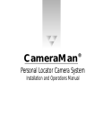
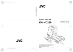
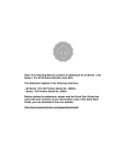
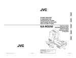
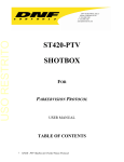
1
CameraMan 1-CCD General Pan/Tilt Camera System Installation and Operations Manual Headquarters: 8493 Baymeadows Way Jacksonville, FL 32256 800-532-8034 904-737-1367 904-731-0958 support@parkervision.com http://www.parkervision.com customer support phone fax e-mail web site CameraMan1-CCD General Pan/Tilt Camera System Installation and Operations Manual 2000 ParkerVision, Inc. Table of Contents MEET YOUR CAMERAMAN ............................... 1-1 GENERAL INFORMATION ...................................................... 1-1 ▼ ▼ About this Manual...........................................................1-1 Support Information........................................................1-1 PRODUCT INFORMATION ...................................................... 1-2 Equipment Checklist ........................................................1-2 Product Description .........................................................1-2 ▼ Upgrade Packages...........................................................1-3 ▼ ▼ Student Camera Upgrade Package ...................................... 1-3 Presenter Camera Upgrade Package.................................... 1-3 Personal Locator Camera Upgrade Package......................... 1-3 Deluxe Camera Upgrade Package........................................ 1-3 ▼ Recommended Accessories .............................................1-4 1-CCD Camera Control Keypad ...................................................... 1-4 SHOT Director ..................................................................... 1-4 CameraMan Tally Light...................................................... 1-4 SCRIPT Viewer Display ......................................................... 1-4 CAMERA SYSTEM COMPONENTS ................................. 1-5 1-CCD CameraMan Camera...........................................1-5 ▼ CameraMan Connector Box ..........................................1-5 ▼ CameraMan Power Supply ............................................1-5 ▼ Connection Accessories ...................................................1-5 ▼ Restraining the Cable Connections.................................. 2-2 Connecting the Video Output ......................................... 2-2 ▼ Connecting to the RS-232 Port........................................ 2-3 ▼ Connecting the Power Supply ......................................... 2-4 ▼ ▼ CONNECTING CAMERA CONTROL DEVICES .............................. 2-5 ▼ ▼ Camera Control Keypad or Tracking System Keypad....... 2-5 SHOT Director................................................................. 2-5 SWITCH CONFIGURATION..................................................... 2-6 ▼ Configuration Table ........................................................ 2-7 SYSTEM STARTUP ............................................................... 2-8 ▼ ▼ Powering Up................................................................... 2-8 Setting Up Gen Lock ....................................................... 2-8 APPENDICES ......................................................... 3-1 A: MULTIPLE CAMERA APPLICATIONS .................................... 3-1 ▼ Daisy-chain Network Configuration ................................. 3-1 B: CAMERA SPECIFICATIONS................................................. 3-2 ▼ ▼ 1-CCD General Pan/Tilt Camera ...................................... 3-2 CameraMan Clearance.................................................. 3-2 Connection Jacks.............................................................1-6 C: TYPICAL SYSTEM DIAGRAM ............................................. 3-3 D: PIN-OUT DIAGRAMS ....................................................... 3-4 E: FIELD OF VIEW SPECIFICATIONS ......................................... 3-5 F: TROUBLESHOOTING......................................................... 3-6 G. WARRANTY INFORMATION .............................................. 3-7 INSTALLATION AND STARTUP ............................ 2-1 INDEX ................................................................... 4-1 CAMERAMAN JACKS AND SWITCHES ................................... 1-6 ▼ MOUNTING YOUR CAMERAMAN CAMERA ............................ 2-1 CONNECTING TO THE CAMERA SYSTEM .................................. 2-2 CameraMan 1-CCD Camera System Installation and Operations Manual iii Section 1 Meet Your CameraMan General Information Your new CameraMan 1-CCD General Pan/Tilt Camera is unmatched in quality, flexibility and expandability, providing you with one of the best video communications cameras in the industry. About this Manual Copyright Information This manual will introduce you to your new CameraMan, explain how to install, connect and configure it, and how to use it in single and multi-camera network applications. In the appendices you'll find diagrams and charts containing technical specifications. The following terms are registered trademarks of ParkerVision, Inc. registered in the United States of America: Throughout this manual, you will see the following icons: ! This icon alerts you to important instructions in the operation and maintenance of your CameraMan system. This icon alerts you to tips or noteworthy suggestions in the operation, use or maintenance of your CameraMan system. Support Information The manufacturer reserves the right to change specifications and warranty at any time without notice or obligation. Refer all warranty and servicing issues to ParkerVision Customer Support at 1-800-532-8034. • • • • • Visibly Better System II IMAGE WhisperDRIVE Plus General Pan/Tilt Camera System The following terms are registered logos of ParkerVision, Inc., registered in the United States of America: • • CameraMan ParkerVision Federal Law prohibits any commercial use of these registered trademarks and logos. No part of this manual may be copied or reproduced without express written consent of ParkerVision, Inc. 1999 ParkerVision, Inc. DURACELL is a registered trademark of Duracell, Inc. CameraMan 1-CCD Camera System Installation and Operations Manual 1-5 Meet Your CameraMan Product Information ParkerVision designed the 1-CCD General Pan/Tilt Camera System for use in a variety of applications. This section provides information on products and packages offered by ParkerVision. You will also find information on upgrade packages and recommended accessories. Equipment Checklist Your 1-CCD General Pan/Tilt Camera System should include the following components: • One 1-CCD CameraMan camera • One CameraMan connector box (not included in Presenter Systems) • One CameraMan power supply • One RS-485 T-connector • One 3' CameraMan communications cable • One 25' CameraMan keypad cable • One 1-CCD Installation and Operations Manual Product Description You can control 1-CCD CameraMan's pan/tilt functions, zoom perspective and IMAGE settings using ParkerVision's Camera Control Keypad, SHOT Director, or Tracking System Keypad. These accessories provide multi-camera control and store up to 99 presets per camera. The camera has a standard 12x lens and offers advanced camera setup functionality and gen locking for glitch-free video switching. 1-6 CameraMan 1-CCD Camera System Installation and Operations Manual Meet Your CameraMan Upgrade Packages The following upgrade packages are available from ParkerVision: Student Camera Upgrade Package Best for: Distance Learning applications. This system allows the camera to respond to a signal from a button on a hard-wired tabletop microphone. To make the camera focus on them, the student presses the button, the camera instantly responds and the gate on the microphone opens. my turn ™ Table-top microphone Includes: Programmable Response Module for distributed preset control and Camera Control Keypad. Presenter Camera Upgrade Package Best for: Distance Learning, Telemedicine and Videoconferencing applications. This system gives presenters and instructors the ability to provide dynamic presentations while the camera automatically follows their every move. Includes: Tracking Ring Package, Tracking System Keypad and Main Docking Station. Tracking Ring Package for Presenter and Deluxe Systems Personal Locator Camera Upgrade Package Best for: Videoconferencing applications. This system gives each videoconferencing participant the power to be instantly identified by the camera with the touch of a MY TURNTM button on individually controlled wireless keypads. Includes: Three RF Personal Locator Keypads and one RF Chairperson Locator Keypad for distributed preset control. Deluxe Camera Upgrade Package This system combines the distributed preset control of the Personal Locator System and the autoTRACKTM presentation capabilities of the Presenter Camera System. Personal Locator Keypad for Personal Locator and Deluxe Systems Includes: Three RF Personal Locator Keypads, one RF Chairperson Locator Keypad, Tracking Ring Package, Tracking System Keypad and Main Docking Station. CameraMan 1-CCD Camera System Installation and Operations Manual 1-7 Meet Your CameraMan Recommended Accessories The following accessories are available from ParkerVision: Camera Control Keypad Camera Select 1 2 3 Camera Controls SHOT Director 1-CCD Camera Control Keypad IN Whether you use it in wireless, RF, or hard-wired mode, the keypad enables you to control the pan, tilt, zoom, focus, iris, gain, and location presets for up to three cameras. The keypad comes standard with the Student Camera System. PAN/TILT ZOOM OUT 1 2 3 4 5 6 7 8 9 0 IMAGE auto IMAGE ENTER Location Presets Some applications require precise and flexible camera control. ParkerVision's SHOT Director is a joystick controller designed to give you the ultimate in single and multi-camera control by allowing you to adjust the pan, tilt, zoom, focus, iris and location presets on up to 16 cameras from one location. SHOT Director is available in standard or autoTRACKTM-equipped models. C a m e ra M a n P A R K E R V I S I O N ® SHOT Director CameraMan Tally Light The CameraMan Tally Light provides a high-intensity visual indication of which camera is selected in a multiple-camera application. You simply install it into the interface on the rear of the camera. The bright red indicator mounts to the top of a flexible shaft, allowing precise adjustment and positioning of the light for the best possible studio-wide observation. CameraMan Tally Light You can control the Tally Light through ParkerVision's CONTROL Center, STUDIO software, or through an external contact closure connected to a side-mounted Phoenix connector. All current 1-CCD cameras are compatible with the Tally Light and previous models are factory-upgradeable. SCRIPT Viewer Display Adding a full-feature teleprompting display that moves with the camera is now available with the addition of ParkerVision's powerful SCRIPT Viewer system. The 12" active-matrix, full-color displays are available separately and mount easily to the camera. Contact your reseller for more information on the complete SCRIPT Viewer system. 1-8 CameraMan 1-CCD Camera System Installation and Operations Manual SCRIPT Viewer Display Meet Your CameraMan 1-CCD Camera System Components This section describes the components that are included with your 1-CCD camera system. 1-CCD CameraMan Camera The CameraMan camera is the primary component and the basis for all of ParkerVision's CameraMan camera systems. CameraMan Connector Box 1-CCD CameraMan Camera The connector box should be attached to the back of the camera. This box is the connection point for all RS-232, RS-485, power and video signals. The only time you would need to remove this box is when you are connecting this camera to a Main Docking Station (included with the Presenter and Deluxe Camera Systems). ! If you purchased a Presenter or Deluxe Camera System, you do not need a connector box. Connector Box CameraMan Power Supply The power supply enables use with 120 VAC sources. ! International Models include a 50/60Hz, 100-240V power supply. Power Supply Connection Accessories • RS-485 T-connector • 3' CameraMan communication cable • 25' CameraMan Keypad cable Top of Tconnector with RS-485 cables. Front and back of T-connector CameraMan 1-CCD Camera System Installation and Operations Manual 1-9 Meet Your CameraMan CameraMan Jacks and Switches All of the connection jacks and configuration switches described below appear on the back of your CameraMan. Do not use telephone cords or jacks for any of the following connections. They are wired differently. ! Connection Jacks Gen Lock Connector • PVI COM Jack – A standard 6-conductor RJ-11 jack used by ParkerVision keypads as a communication interface to the camera system. For example, a hard-wired keypad attaches here. • RS-485 Jack – A standard 4-conductor modular telephone jack used for RS-485 communications between the camera and other ParkerVision devices. You can use this jack to network multiple cameras or to connect appropriate ParkerVision-approved peripherals using a ParkerVision T-connector. • Auxiliary Communication Port – Provides communications to select ParkerVision peripherals and provides capability for future expansion. • RS-232 Port – A standard DB-9 female connector that provides RS-232 communications to external devices such as PCs or other vendor control systems. • S-VIDEO Jack – A standard min-DIN jack that provides direct S-VIDEO video output. S-VIDEO cable is not provided. • Cable Restrainer – Helps keep cables from becoming dislodged or hindering the pan and tilt of the camera. • Composite Video Jack – A standard BNC-type jack that provides direct composite video output. Video cable is not provided. • DC Power Jack - Power input for the CameraMan camera. Plug only a ParkerVision power supply (included) into this jack. Do not use any other type of power supply. This item is not used with Presenter Systems. • Power – Use this switch to power on/off the CameraMan camera. • Tally Light Port – Provides output and external control for the CameraMan Tally Light. • Gen Lock Connector – Provides input and external control for setting up Gen Lock. If you purchased a Presenter or Deluxe Camera System, refer to their respective manuals for information on the Main Docking Station that replaces the connector box. ! 1-10 S-VI DEO SWI TCH BA NK -A- SWI TCH BA NK -BCOM POSI TE 1 2 3 4 5 6 7 8 BAS E UNI T AD DRESS 1 2 3 4 5 6 7 8 UP DOWN Back of 1-CCD camera with connector box attached and configuration plate removed. CameraMan 1-CCD Camera System Installation and Operations Manual Ports and Jacks TALLY LIGHT INTERFACE Tally Light Port TALLY LIGHT INTERFACE Section 2 Installation and Startup Mounting Your CameraMan Camera You can mount your CameraMan camera on any flat, non-slick, nonmetal surface with a minimum supporting area of 8" x 8". Follow the instructions below: 1. ! 2. ! 3. ! ! Check your selected camera location to ensure that you have enough camera and cable clearance space for the CameraMan camera to pan and tilt without obstruction. Do not mount the camera upside down or with more than a 10 degree angle from horizontal. Refer to Appendix E, Field of View Specifications, to assist you with positioning the CameraMan camera to achieve optimum optical views. Locate the zero-degree position mark labeled "Front" on the bottom of the base unit. This mark helps ensure that the base unit is calibrated correctly. Point this indicator mark in the direction that best reflects the center of travel for the camera. (This is usually the center of the room.) 18.0” x 12.0” 22.0” 3.0” x Lift the unit by its base, not by its tilt assembly. To ensure that the mounting surface is not prone to vibrations, fasten the camera to a flat, rigid surface using a 1/4"-20 UNC cap screw that does not extend into the base platform by more than 0.4". (The cap screw is not included.) To use a 3/8"16 UNC cap screw, remove the insert provided in the mounting screw hole. To avoid overtightening, tighten this screw by hand. If necessary, use a non-hardening threadlock to prevent the screw from loosening. Overtightening can prevent the camera from panning properly and may damage the unit. Never attempt pan or tilt movement by hand. Always use a control device. Always operate the camera indoors and follow the temperature and humidity specifications outlined in Appendix B, Camera Specifications. Zero degree pan position mark 3/8"-16 UNC Mounting Screw Hole with 1/4"-20 UNC insert. CameraMan 1-CCD Camera System Installation and Operations Manual 2-11 Installation and Startup Connecting to the Camera System This section provides connection instructions. Refer to the left-side connection ports. Restraining the Cable Connections For the following camera connections: • Run the cables through the cable restrainer from left to right. • Tighten the cable restrainer to prevent any cables from dislodging. This should result in the cables being located approximately in the center of the camera, instead of near the edge. PVI COM RS-232 RS-485 A UX A S-VI DEO OUT COM POSITE VID EO OUT DC POWER POWER ! To relieve stress on the camera and the cable connections, fasten all cables using the cable restrainer on the back of the camera. Feed cables from left to right through the restrainer. Connecting the Video Output ! CameraMan supports both composite and S-VIDEO formats, although you can use only one at a time. For composite format, connect to the BNC jack on the Connector Box on the back of the camera, labeled COMPOSITE VIDEO OUT, using a standard coaxial cable with a BNC connector (not provided). ! Verify that the Video Select switch is set to COMPOSITE. The switch is located behind the switch plate on the back right of the camera. Refer to the "Switch Configuration" topic in this section. For S-VIDEO format, connect to the S-VIDEO jack on the back of the camera using a standard S-VIDEO cable (not provided). S-VIDEO and Composite Video Out Jacks 2-12 CameraMan 1-CCD Camera System Installation and Operations Manual Installation and Startup ! Verify that the Video Select switch is set to S-VIDEO. The switch is located behind the switch plate on the back right of the camera. Refer to the "Switch Configuration" topic in this section. For video output specifications, refer to Appendix B, Camera Specifications. Connecting to the RS-232 Port COM light CameraMan provides for RS-232 communications using the DB-9 jack on the back of the camera, labeled RS-232. You can use this port to control the camera using external devices such as a PC or other vendor-control system such as AMXTM and CrestonTM. Our RS-232 protocol is available by calling Customer Support at (800)532-8034. Connect to this port using a standard computer cable with a DB-9 connector. This port operates with No Parity and software handshaking using ParkerVision High Reliability or Basic protocols. ! Verify the protocol being used by checking the Protocol switch on the camera. Refer to the "Switch Configuration" topic in this section. The COM light above the RS-232 port is used to indicate communication activity. For the DB-9 pin-out port information, refer to Appendix D, Pin-out Diagrams. CameraMan 1-CCD Camera System Installation and Operations Manual 2-13 Installation and Startup Connecting the Power Supply You can mount the power supply with any orientation or on top of a table or roll-about unit. Follow the steps below: 1. Verify that the power switch located on the back of the camera is turned off. 2. Plug the 5.5mm female connector of the power supply into the DC POWER jack on the back of the camera. 3. Connect the other end of the power supply into a 120 VAC source. PVI COM RS-232 RS-485 AUX A S-VI DEO OUT COM POSITE VIDEO OUT DC POWER POWER ! 2-14 Do not modify the length of the AC or the DC wiring. CameraMan 1-CCD Camera System Installation and Operations Manual POWER Installation and Startup Connecting Camera Control Devices There are several ways to control your camera's movement. The following information explains how to connect and configure the optional Camera Control Keypad and the SHOT Director. Camera Control Keypad or Tracking System Keypad The optional Camera Control Keypad controls the camera's movement via wireless RF technology up to 60', or hard-wired connection up to 250'. If you choose to use a Camera Control Keypad in the hard-wired mode, follow the installation directions below: 678 0 1 23 45 DEF Connect the other end of the cable to the RJ-11 type jack on the back of the camera, labeled PVI COM. Camera Control Keypad connected via PVI COM Port 9A B 2. Connect one end of the 25' CameraMan Keypad Cable included with your camera to the RJ-11 type jack located in the battery compartment of the keypad. C 1. When the system is powered on, the light on the keypad illuminates momentarily and you will hear two beeps indicating that the keypad is ready for operation. The light located above the PVI COM port indicates communication activity. Use only the cable supplied by ParkerVision for the PVI COM port. Using non-ParkerVision cables such as telephone cords may cause damage. ! S-VIDEO SWITCH BANK -A- SWITCH BANK -BCOMPOSITE SHOT Director 1 2 3 4 5 6 7 8 BASE UNIT ADDRESS 1 2 3 4 5 6 7 8 T ALLY LIGHT IN T ERFA CE UP D OW N You can connect the optional SHOT Director joystick controller in hard-wired mode only. To connect the SHOT Director to your camera: 1. Connect one end of the RS-485 cable to one of the RS-485 jacks on the back of the SHOT Director. 2. Connect the other end of the cable to one of the following: SHOT Director connected via RS-485 LCD CONTRAST COM 1 ✦ For single camera applications, use the jack labeled RS-485 on the back of the CameraMan connector box. ✦ For multiple camera applications, use the T-connector. Use the 3' CameraMan communications cable (provided) to connect the T-connector the camera's RS-485 jack. Longer cables are available. LCD BRIGHT NESS RS-48 5 18 -2 0 VDC 1 CameraMan 1-CCD Camera System Installation and Operations Manual 2-15 Installation and Startup Switch Configuration Now that you have connected your camera to the power supply and control devices, you need to configure the camera to work in your specific application. To begin, remove the switch plate on the back right side of the camera by removing the two screws holding it in place. Behind the plate you will see all of the configuration switches. Refer to the next page for a table describing the switches. S-VI DEO SWI TCH BA NK -A- SWI TCH BA NK -BCOMPOSI TE 1 2 3 4 5 6 7 8 UP DOWN Video Out Switch S-VIDEO This diagram shows the default switch configuration of the camera as shipped. SWITCH BANK -A- SWITCH BANK -BCOMPOSITE 1 2 3 4 5 6 7 8 BASE UNIT ADDRESS Up 1 2 3 4 5 6 7 8 UP Down DOWN Switches A1 – A8 2-16 Base Unit Switches B1 – B8 Address Switch CameraMan 1-CCD Camera System Installation and Operations Manual BA SE UNI T AD DRESS 1 2 3 4 5 6 7 8 TALLY LIGHT INTERFACE Installation and Startup Configuration Table ! Switch Number A1 A2 A3 A4 A5 & A6 A7 A8 After changing any switch settings, turn off the camera and then turn it back on to activate the change. Description Lens Select Sub-carrier Coarse Adjustment -Lens Converter Type -Baud Rate Memory Lock DOWN Position Normal UP Position Adapter Factory Default DOWN 0° 180° DOWN Use this switch to change the sub-carrier phase from 0° to 180°. -Wide --- DOWN DOWN NOT USED Use this switch with switch A1 to select the type of lens adapter being used. Always set to the DOWN position. -9600 Lock -19200 Unlock DOWN UP UP NOT USED Use this switch to configure the camera's baud rate for the RS-232 and RS-485 ports. For the majority of applications, use this switch in the UP (Unlock) position to prevent programmed settings from being accidentally overriden. Use this switch to set the video source to composite (DOWN) or S-VIDEO (UP). You must choose one source, you cannot use them simultaneously. Function Use this switch with Personal Locator and Deluxe Camera Systems to indicate the use of a lens adapter. Refer to their manuals for more information. Video Out Composite/SVIDEO Composite S-VIDEO DOWN Base Unit Address -- -- -- Zero (0) Use this 16-position rotary switch to set the unique identification number of your camera. If you use the optional keypad, SHOT Director, or another control system, refer to the documentation provided with those accessories for proper configuration. For setting up a camera network, refer to Appendix A, Multiple Camera Applications. B1 Protocol High Reliability Basic DOWN B2 Data Source Local Remote DOWN B3 B4 Digital Zoom RF Command Off Enable On Disable DOWN DOWN Use this switch to select the communication protocol to be used by the RS-232 and RS-485 ports. The High Reliability protocol includes some advanced error checking that is not performed in the Basic protocol. Use this switch to determine whether the camera will receive data from a local source such as a keypad, or from a remote source, such as a SHOT Director. Use this switch to turn on or off the digital zoom feature. Use this switch to enable/disable the camera to respond to commands sent from an RF Keypad. When using multiple cameras networked on the RS-485 bus, only one camera should have its RF receiver enabled. Set switch B4 on the other cameras to Disable (UP). ! ! B5 Preset Save B6 & B7 B8 -Interlink Manual Gain, Iris and Focus -Enable Auto Settings DOWN -Disable DOWN DOWN Use this switch to determine how the preset settings will be saved. DOWN saves your Manual Gain, Iris and Focus settings. UP saves only the Auto settings for presets and autoTRACK views. NOT USED Use this switch in multi-camera applications. The DOWN position passes all commands through the RS-485 communication bus to the appropriate camera. This switch has no effect in a single camera application. CameraMan 1-CCD Camera System Installation and Operations Manual 2-17 Installation and Startup System Startup Once you have made all of the necessary connections and configured the camera to your application, you are ready to turn on the system. Powering Up To turn on the system: 1. Switch the Power button on the back of the camera to the ON position. The camera should automatically enter its positioncalibration mode and stop at the zero-degree pan/tilt point. 2. Verify that the camera is now facing in the direction the FRONT label was pointing during mounting. Refer to the "Mounting Your CameraMan Camera" topic in this section. 3. If you are using the optional Camera Control Keypad, make sure its address is the same as the address on the camera. Also verify that the camera's pan and tilt functions are working properly. If the camera does not move, refer to the Troubleshooting section of your Camera Control Keypad or SHOT Director manual. PVI COM RS -2 32 RS-48 5 AUX A S-VI DEO OUT COM POSITE VID EO OUT DC POWER POWER POWER Setting Up Gen Lock Refer to either of the following manuals for instructions on adjusting gen lock timing parameters: • CameraMan 1-CCD Camera Control Keypad Operations Manual • SHOT Director Installation and Operations Manual 2-18 CameraMan 1-CCD Camera System Installation and Operations Manual Section 3 Appendices A: Multiple Camera Applications If your application requires that you have more than one CameraMan, you will need to set them up in a daisy-chain network configuration. Daisy-chain Network Configuration To daisy-chain your cameras: 1. 2. 3. SWI TCH BA NK -BCOMPOSI TE 1 2 3 4 5 6 7 8 BA SE UNI T ADDRESS 1 2 3 4 5 6 7 8 TALLY LIGHT INTERFACE Camera 1 Pin 3 . . . . Pin 3 Pin 4 . . . . Pin 4 Do not use a standard phone cable. These are wired differently and may cause damage. BASE UNIT ADDRESS Using the BASE UNIT ADDRESS rotary switch located on the back of the camera, configure each camera with a unique base unit address. EXAMPLE: Camera 1 set with address 0, camera 2 set with address 1, etc. 4. S-VI DEO SWI TCH BA NK -A- UP DOWN Connect each camera using a 4-conductor cable with 4-position modular handset plugs wired straight-through: Pin 1 . . . . Pin 1 Pin 2 . . . . Pin 2 ! BASE UNIT ADDRESS To connect the cameras together, plug one end of the CameraMan communication cable into the ParkerVision Tconnector and plug the other end into the RS-485 port on the back of the camera. S-VI DEO SWI TCH BA NK -A- SWI TCH BA NK -BCO MPOSI TE 1 2 3 4 5 6 7 8 BA SE UNI T ADDRESS 1 2 3 4 5 6 7 8 TALLY LIGHT INTERFACE UP DOWN T-Connector Camera 2 In order to control each camera with your Camera Control Keypad, the rotary switch inside the keypad battery compartment must match the lowest base unit address in your system. Only one base unit should have its RF enabled. Refer to the "Switch Configuration" topic of Section 2, Installation and Statup. BASE UNIT ADDRESS S-VIDEO SWI TCH BA NK -A- SWI TCH BA NK -BCOM POSITE EXAMPLE: If the BASE UNIT ADDRESS switches are set according to the illustration to the right, the rotary switch inside the keypad should be set to 0. The Camera Control Keypad can control up to 3 cameras. Refer to the "Camera Control Keypad" topic of Section 2, Installation and Startup. 1 2 3 4 5 6 7 8 BA SE UNI T AD DRESS 1 2 3 4 5 6 7 8 TALLYLIGHT INTERFACE UP DOWN Camera 3 CameraMan 1-CCD Camera System Installation and Operations Manual 3-2 Appendices B: Camera Specifications This device complies with part 15 of the FCC rules. Operation is subject to the condition that this device does not cause harmful interference. FCC identifier: JFECM003-AA 1-CCD General Pan/Tilt Camera Image Sensor ................................ 1/3" IT CCD Picture Elements............................ NTSC: 768 (H) x 494 (V) PAL: 752 (H) x 582 (V) Angle of View ............................... Hor: 48.8° to 4.3° Vert: 37.6° to 3.3° Lens Converter Options ................. Wide Angle (.65x) Shortest Subject Dist ..................... 10 mm (wide) to 800 mm (tele) Hor. Resolution ............................. NTSC: 460+ TV lines PAL: 450+ TV lines Vert. Resolution............................. NTSC: 350+ TV lines PAL: 400+ TV lines Min. Illumination ........................... 7 lux F1.8: More than 50 IRE S/N Ratio ...................................... More than 48 dB White Balance ............................... Auto/TTL Auto Tracing/Preset Electronic Shutter .......................... NTSC: 27 steps (1/60 to 1/10000 sec) PAL: 28 steps 1/50 to 1/10000 sec) Flickerless ...................................... Automatic Focus Control ................................ Automatic or Manual Image Control .............................Automatic or Manual Mechanical Devices .....................WhisperDRIVE PlusTM rated for 5000 hrs of continuous motion Temperature ............................... 32° to 100°F (0° to 37.78°C) Video Out (75 ohm) .................... Composite or S-VIDEO NTSC VBS: 1.0 Vp-p Composite Y: 1.0 Vp-p Sync Negative C: Burst 0.286 Vp-p PAL VBS: 1.0 Vp-p Composite Y: 1.0 Vp-p Sync Negative C: Burst 0.300 Vp-p RS-232 Port ................................. DB-9 female connector RS-485 Port ................................. Bus up to 16 cameras (4 Pos. RJ handset port) Power ......................................... US: 120V, 60Hz AC INT: 100-240VAC, 50-60Hz 100W maximum consumption Genlock ...................................... VBS Genlock Phase Control.............................. H/SC Phase control Humidity ..................................... 0 to 95% non-condensing Dimensions ................................. US: 9.25"L x 12.75"W x 10.75"H INT: 23.5cmL x 32.38cmW x 27.31cmH Weight........................................ 14 lbs. (6.35 Kg) Tilt ..............................................±25° (speed: 1°/sec to 50°/sec) Pan .............................................359° (speed: 1°/sec to 65°/sec) Location Presets ..........................125 via software or CCK Location Preset Accuracy ............... ± .125° CameraMan Clearance The minimum dimension for the CameraMan is a circular diameter of 22". This accounts for both camera and cable clearance. Refer to the "Mounting Your CameraMan Camera" topic of section 2, Installation and Startup. CameraMan 1-CCD Camera System Installation and Operations Manual 3-3 Appendices C: Typical System Diagram Below is a typical setup for your CameraMan camera. The items in the diagram are not to scale. Power Supply PVI COM 1 2 RS-485 RS-232 Composite Video Out AMX™ OR Creston™ IN 1 2 3 4 5 6 7 8 9 0 Video Output aut o IMAGE ENTER Locat ion Presets C am eraM an ® P A R K E R V I S I O N Camera Control 3-4 S-Video Out 3 CameraMan 1-CCD Camera System Installation and Operations Manual Appendices D: Pin-out Diagrams You'll find the following pin-out connections on the back of the CameraMan connection box. Y 4 1 RS-485 Four position Module Handset Pin Signal___ 1 2 3 4 Ground Signal A Signal B Ground Pin Signal___ 1 2 3 4 5 6 12v 12v Ground Signal A Signal B Ground C C Ground Y Ground S-VIDEO Connector Video (1Vpp) 6 1 PVI COM RJ-11 Ground Composite Video BNC Connector + 18v DC 5 9 1 6 9-pin Female DB-9 Sub Pin Signal____ 2 3 5 1,4, 6-9 Transmit Receive Ground Not used Ground 5.5mm DC Power Connector CameraMan 1-CCD Camera System Installation and Operations Manual 3-5 Appendices E: Field of View Specifications The following reference charts represent the size of your field of view and angle of view from various distances and magnifications, and with different lenses. 9.07 ft Standard Lens: 12x zoom (f.l. = 5.4 to 64.8mm): 6.81 ft 48.8° 37.6° Full Zoom Horizontal (ft) Vertical (ft) .75 .58 1.13 .86 1.50 1.15 1.88 1.44 2.25 1.73 2.63 2.02 3.00 2.30 3.38 2.59 3.75 2.88 4.13 3.17 4.51 3.46 4.88 3.74 5.26 4.03 4.3° No Zoom Horizontal (ft) Vertical (ft) 14.28 10.33 21.42 15.49 28.56 20.65 35.70 25.82 42.84 30.98 49.98 36.15 57.12 41.31 64.26 46.47 71.40 51.64 78.53 56.80 85.67 61.96 92.81 67.13 99.95 72.29 10 feet 18.14 ft 13.62 ft 20 feet 3.3° Wide Angle Lens Adapter: 0.65x (f.l. = 3.4 to 42.1 mm): Distance from Lens (feet) 10 15 20 25 30 35 40 45 50 55 60 65 70 Example of distance's impact on field of view taken from a standard lens table (10 feet and 20 feet) Full Zoom Horizontal (ft) Vertical (ft) 1.16 0.88 1.74 1.32 2.32 1.76 2.90 2.20 3.48 2.64 4.05 3.07 4.63 3.51 5.21 3.95 5.79 4.39 6.37 4.83 6.95 5.27 7.53 5.71 8.11 6.15 zoom Angle of View No Zoom Horizontal (ft) Vertical (ft) 9.07 6.81 13.61 10.21 18.14 13.62 22.68 17.02 27.22 20.43 31.75 23.83 36.29 27.23 40.83 30.64 45.36 34.04 49.90 37.45 54.43 40.85 58.97 44.26 63.51 47.66 no zoom Distance from Lens (feet) 10 15 20 25 30 35 40 45 50 55 60 65 70 no zoom = wide angle (more scenery, Above – Vertical angle of view Below – Horizontal angle of view less specific detail) zoom = narrow angle (less scenery, more specific detail) zoom no zoom Angle of View 3-6 71.05° 54.62° 6.63° 5.03° CameraMan 1-CCD Camera System Installation and Operations Manual Appendices F: Troubleshooting If you experience problems with your CameraMan system, use the following troubleshooting steps for assistance. If you are unable to resolve the problem, contact ParkerVision Customer Support at (800) 532-8034. ! As you go through this section, make notes about error messages or operation anomalies to discuss with Support personnel if you need to contact them. Please be near the equipment when calling. Problem The camera's video is not working properly. Solution 1. Verify that the VIDEO SELECT switch on the back of the camera is set properly. 2. Verify that the appropriate video connection is being used on the back of the camera— either S-VIDEO or COMPOSITE VIDEO OUT, BUT NOT BOTH. 3. Verify that the video output of the camera is connected to the appropriate video input on the switcher, CODEC, or monitor. 4. Verify that the video cables are good. Try a different one if possible. 5. Verify that the monitor(s) is working. S-VIDEO COMPOSITE S-VI DEO SWITCH BA NK -ABA SE UNI T AD DRESS 1 2 3 4 5 6 7 8 TALLY LIGHT INTERFACE UP DOWN Problem There are no communications through the RS-232 port. Solution 1. Verify that the cable is wired correctly. 2. Verify that Switch Bank B - Switch 1 (PROTOCOL SELECT) on the back of the camera is set properly. 3. Verify that Switch Bank A – Switch 7 (BAUD RATE) on the back of the camera is set properly. 4. Verify that the BASE UNIT ADDRESS switch is set properly. 5. Does the COM light above the RS-232 port on the back of the camera blink when you send a command through this port? If no, change the cable and retry. ! SWITCH BA NK -BCOMPOSI TE 1 2 3 4 5 6 7 8 S-VIDEO SWITCH BANK -A- SWITCH BANK -BCOMPOSITE 1 2 3 4 5 6 7 8 BASE UNIT ADDRESS Up 1 2 3 4 5 6 7 8 UP Down DOWN BASE UNIT ADDRESS Verify that you are not using a null-modem cable. CameraMan 1-CCD Camera System Installation and Operations Manual 3-7 Appendices G. Warranty Information This appendix provides warranty information on the CameraMan 1-CCD General Pan/Tilt Camera System. ParkerVision One-Year Limited Warranty The Warranty is voided if... • • • • • • • • • • ParkerVision warrants to the end user that this product will be free from defects in material and/or workmanship for a one-year period commencing on the date of delivery, except where expressly noted. Proof of Purchase: ParkerVision’s authorized Dealer’s dated bill of sale must be retained as evidence of the date of purchase and to establish warranty eligibility. ParkerVision will correct all defects in material or workmanship, or any failure of the system to perform to specifications during the warranty period, at no charge for parts and labor. The original purchaser must notify ParkerVision, in writing, before the warranty period has expired in the event of a defect in material or workmanship, or failure of the system to perform to specifications. If damage occurs during shipment from the ParkerVision factory, ParkerVision must be notified within five working days of receipt of the product in order to make a claim. ParkerVision is not obligated at any time to provide the purchaser with a substitute unit. The warranty is not extended due to purchasing new products and/or upgrading your original product. The warranty is non-transferable. Purchaser’s failure to make a claim as provided above or continued use of the product shall constitute an unqualified acceptance of such product and a waiver by purchaser of all claims. • • • • • • The product is damaged in shipping other than the original shipment from the ParkerVision factory. The product is used outside of the specifications or operating guidelines, as outlined in the ParkerVision product manuals. The product has sustained physical damage from misuse or abuse. The product has sustained damage due to a natural disaster such as fire, lightning, earthquake, etc. The product is damaged by non-ParkerVision peripherals. A person not authorized by ParkerVision has attempted to/or has serviced the equipment. The product’s identification (serial numbers, trademarks, etc.) is removed, defaced, or altered. Return Policies Contact your authorized ParkerVision Reseller for return procedures. Product Warranty Registration Form Extended Service and Support • For details on extended service and support, please contact ParkerVision's Customer Service Department. • • 3-8 The warranty period begins the day your ParkerVision product is received. Product Warranty Registration is required to ensure your product receives prompt attention if warranty work is ever necessary. Please see your product warranty registration form, which is packaged with every product, for details on enrolling. CameraMan 1-CCD Camera System Installation and Operations Manual Appendices CameraMan 1-CCD Camera System Installation and Operations Manual 3-9 Section 4 Index A AC/DC, 2-3 accessories, 1-4 connection, 1-5 AMX, 2-3 angle of view, 3-2 appendices, 3-1 auxiliary communication port, 1-6 B base unit address, 3-1, 3-6 baud rate, 3-6 C cable restrainer, 1-6, 2-2 camera clearance, 3-2 components, 1-5 control devices, 2-4 control keypad, 2-4 mounting instructions, 2-1 power supply, 2-3 specifications, 3-2 weight, 3-2 camera applications multiple, 3-1 camera connection ports, 2-2 camera control keypad, 1-4 cameras daisy-chain, 3-1 checklist equipment, 1-2 CODEC, 3-6 COM light, 3-6 components camera, 1-5 composite video jack, 1-6, 2-2 composite video out, 3-6 configuration multiple camera applications, 3-1 configuration, switch, 2-5 connecting power to the camera, 2-3 connecting to the camera system, 2-2 connection accessories, 1-5 connection ports, 2-2 connections auxiliary communication port, 1-6 composite video jack, 1-6 DC power jack, 1-6 gen lock, 1-6 jacks and switches, 1-6 PVI COM, 1-6 RS-232, 1-6 RS-232 communications, 2-3 RS-485, 1-6 S-VIDEO jack, 1-6 tally light port, 1-6 video output, 2-2 connector box, 1-5 CONTROL Center, 1-4 control devices for the camera, 2-4 Creston, 2-3 customer support, 3-6 D DC power jack, 1-6 deluxe camera upgrade, 1-3 diagrams camera setup, 3-3 CameraMan 1-CCD Camera System Installation and Operations Manual 4-10 Index connector box, 3-4 pin-outs, 3-4 dimensions, 3-2 distance learning, 1-3 upgrade packages, 1-3 installation and setup, 2-1 instructions for connecting to the camera system, 2-2 introduction to CameraMan, 1-1 E J electronic shutter, 3-2 equipment checklist, 1-2 jacks auxiliary communication port, 1-6 composite video, 1-6 DC power, 1-6 gen lock, 1-6 PVI COM, 1-6 RS-232 port, 1-6 RS-485, 1-6 S-VIDEO, 1-6 tally light port, 1-6 jacks and switches, 1-6 JFECM003-AA identifier, 3-2 joystick, SHOT Director, 2-4 F field of view specifications, 3-5 flickerless, 3-2 focus control, 3-2 G gen lock connector, 1-6 gen lock, setting up, 2-7 general information, 1-1 genlock, 3-2 guarantee, warranty information, 3-7 H help customer support, 1-1; 3-6 troubleshooting, 3-6 horizontal resolution, 3-2 how to use this manual, 1-1 humidity, 3-2 I icons used in this manual, 1-1 illumination, 3-2 image control, 3-2 image sensor, 3-2 indicator light, 1-4 information about this manual, 1-1 customer support, 1-1 general, 1-1 product, 1-2 K keypad Camera Control, 2-5 Tracking System, 1-3 keypads Camera Control, 1-4 RF tracking, 1-3 L lens wide angle, 3-5 lens options, 3-2 location preset accuracy, 3-2 location presets, 3-2 M main docking station, 1-3, 1-6 mechanical devices, 3-2 minimum illumination, 3-2 mounting your camera, 2-1 multiple camera applications, 3-1 MY TURN, 1-3 CameraMan 1-CCD Camera System Installation and Operations Manual 4-11 Index N S networking daisy-chain, 3-1 multiple cameras, 3-1 no parity, 2-3 NTSC, 3-2 S/N ratio, 3-2 SCRIPT Viewer display, 1-4 setting up gen lock, 2-7 setting up your camera, 2-1 setup and installation, 2-1 shortest subject distance, 3-2 SHOT Director, 1-4 SHOT Director joystick controller connection, 2-4 shutter, 3-2 specifications camera, 3-2 field of view, 3-5 starting up the system, 2-7 student camera package upgrade, 1-3 STUDIO software, 1-4 support customer, 3-6 support information, 1-1 S-VIDEO, 3-6 S-VIDEO jack, 1-6, 2-2 switch configuration, 2-5 table, 2-6 switches base unit address, 3-1 switches and jacks, 1-6 system diagram, 3-3 system startup, 2-7 P PAL, 3-2 pan, 3-2 Personal Locator camera upgrade, 1-3 phase control, 3-2 picture elements, 3-2 pin-out diagrams, 3-4 ports auxiliary communication, 1-6 composite video, 1-6 connections, 2-2 DC power jack, 1-6 gen lock, 1-6 PVI COM, 1-6 RS-232, 1-6, 3-2 RS-485, 1-6, 3-2 S_VIDEO, 1-6 tally light, 1-6 power specifications, 3-2 power supply, 1-5 power supply, camera, 2-3 powering up, 2-7 Presenter camera upgrade package, 1-3 preset control, 1-3 product information, 1-2 protocol, 3-6 PVI COM jack, 1-6 PVI COM port, 2-4 R resolution, 3-2 RS-232 port, 1-6, 2-3, 3-2 RS-485 jack, 1-6 RS-485 port, 3-2 T tally light, 1-4 tally light port, 1-6 telemedicine, 1-3 temperature, 3-2 tilt, 3-2 tracking ring, 1-3 tracking system keypad, 2-4 tracking, RF keypad, 1-3 troubleshooting, 3-6 U UNC cap screw, 2-1 upgrade information, 1-3 using multiple cameras, 3-1 4-12 CameraMan 1-CCD Camera System Installation and Operations Manual Index V VAC source, 2-3 VAC sources, 1-5 vertical resolution, 3-2 video out, 3-2 video output connections, 2-2 videoconferencing, 1-3 W warranty information, 3-7 white balance, 3-2 wide angle lens, 3-5 Z zoom, 3-5 CameraMan 1-CCD Camera System Installation and Operations Manual 4-13 2000 ParkerVision, Inc. Literature Part Number L1204101 (REF# LPMCPT1B) Revision D