1
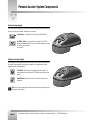
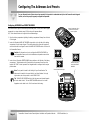
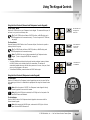
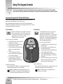
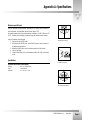
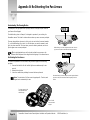
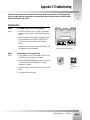
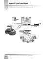
CameraMan
®
Personal Locator Camera System
Installation and Operations Manual
Table Of Contents
I. Meet Your Personal Locator
▼ Congratulations on your Purchase . . . . . . . . . . . . . . . . . . . . . . . . . . . . . . 1
▼ Product Description . . . . . . . . . . . . . . . . . . . . . . . . . . . . . . . . . . . . . . . . 1
▼ Personal Locator System Components
• Personal Locator Keypad . . . . . . . . . . . . . . . . . . . . . . . . . . . . . . . . . . 2
• Chairperson Locator Keypad . . . . . . . . . . . . . . . . . . . . . . . . . . . . . . . 2
▼ Locator Keypad Controls. . . . . . . . . . . . . . . . . . . . . . . . . . . . . . . . . . . . . 3
II. Configure Your Personal Locator
▼ Configuring the Addresses and Presets . . . . . . . . . . . . . . . . . . . . . . . . . . 4
▼ Start-Up and Set-Up
• Start-Up . . . . . . . . . . . . . . . . . . . . . . . . . . . . . . . . . . . . . . . . . . . . . . 5
• Setting Up the Videoconference. . . . . . . . . . . . . . . . . . . . . . . . . . . . . 5
III. Use Your Personal Locator
▼ Using the Keypad Controls
• Using the Back Controls . . . . . . . . . . . . . . . . . . . . . . . . . . . . . . . . . . 6
• Using the Front Controls (Chairperson and Personal Locator Keypads). . 7
• Using the Front Controls (Chairperson Locator Keypads) . . . . . . . . . . . 7
• Programming/Changing the MY TURN and GROUP buttons. . . . . . . . . 8
IV. Appendices
▼ A: Specifications . . . . . . . . . . . . . . . . . . . . . . . . . . . . . . . . . . . . . . . . . . 9
▼ B: Re-Orienting the Pan Arrows. . . . . . . . . . . . . . . . . . . . . . . . . . . . . . . 10
▼ C: Troubleshooting. . . . . . . . . . . . . . . . . . . . . . . . . . . . . . . . . . . . . . . . 11
▼ D: Typical System Diagram . . . . . . . . . . . . . . . . . . . . . . . . . . . . . . . . . . 12
he terms Visibly Better, System II, IMAGE, WhisperDRIVE Plus, Personal Locator System, MY
TURN, SHAREVIEW and General Pan/Tilt Camera System are registered trademarks of
ParkerVision, Inc. in the United States of America. The terms CameraMan and ParkerVision are
registered logos in the United States of America. Any commercial Use of these registered
trademarks and logos is prohibited by federal law.
The manufacturer reserves the right to change specifications and warranty at any time without
notice or obligation.
Refer all Warranty and Servicing to the ParkerVision Consumer Center listed in the back of the
installation and operations manual that came with your CameraMan camera.
No part of this manual may be copied or reproduced without express written consent of
ParkerVision, Inc. © 1997 ParkerVision, Inc.
8493 Baymeadows Way
Jacksonville, FL 32256
800-532-8034
904-737-1367
904-731-0958
support@parkervision.com
http://www.parkervision.com
CameraMan® Personal Locator Camera System Installation and Operations Manual • © 1998 ParkerVision, Inc.
phone
fax
e-mail
website
Congratulations On Your Purchase
Your new CameraMan Personal Locator Camera System will help make your videoconferences more dynamic and effective by
giving you and your videoconferencing participants the ability to appear, and be heard on screen whenever you desire to
participate in the conversation.
This manual covers the connection, configuration and use of your new Personal Locator
Camera System. Along with basic pan, tilt, zoom, and IMAGE control of your CameraMan
camera, the Personal Locator System includes ParkerVision’s Personal Locator Keypads and a
Chairperson Locator Keypad, which provides each participant with distributed preset control.
This manual is designed to be used in conjunction with the installation and operations manual
that came with your 1-CCD or 3-CCD CameraMan Camera. If you have questions about the
installation, configuration or use of the camera, refer to that manual.
Your Personal Locator Camera System should
include these components:
•
•
•
•
One 1-CCD or 3-CCD Chairperson Locator Keypad
Three 1-CCD or 3-CCD Personal Locator Keypads
One Personal Locator Camera System Operations Manual
One Personal Locator Quick Reference Card
You’ll see three icons in this manual:
This icon alerts you to important instructions in the operation and maintenance of
your Personal Locator System.
This icon alerts you to tips or noteworthy suggestions in the operation, use or
maintenance of your Personal Locator System
This icon refers you to the 1-CCD or 3-CCD General Pan/Tilt Camera installations
and operations manual that came with your camera.
Product Description
The CameraMan Personal Locator Camera System is a robotic camera system with distributed
preset control used in videoconferencing applications. The Personal Locator Camera System
consists of the CameraMan Camera, 3 wireless RF Personal Locator Keypads, and 1 wireless RF
Chairperson Locator Keypad.
Note: If you have purchased this as an upgrade, it will include all components except
the camera.
This system gives each videoconferencing participant the power to be instantly identified by the
camera with the touch of a MY TURN button on individually controlled keypads. When the MY
TURN button is pressed, the CameraMan automatically zooms, pans and tilts to focus on that
participant. The Locator Keypads also provide each videoconference participant with camera
control capabilities, eliminating the need for a single camera operator. The system can
accommodate up to 99 Personal Locator Keypads.
The 1-CCD Personal Locator Systems are also equipped with SHAREVIEW, a unique technology
that allows two participants to share the camera view. Once activated, the camera will
automatically calculate the proper view for the active participants.
© 1998 ParkerVision, Inc. • Meet Your Personal Locator Camera System
Page 1
Personal Locator System Components
Personal Locator Keypad
The Personal Locator Keypad gives each videoconference participant distributed preset control.
So at any time during the meeting, individuals can choose from:
Group Button– A wide-angle shot of the group, or SHAREVIEW, or
MY TURN™ Button– A close-up shot of themselves The MY TURN
feature gives distributed camera control so that each participant can easily
control how they are viewed
on the screen.
Chairperson Locator Keypad
The Chairperson Locator Keypad provides the same Group, and MY TURN™ shot features as
the Personal Locator Keypads, but also gives the chairperson, or meeting leader, override
capabilities with the following buttons:
LOCK Button– When pressed, the meeting leader can “lock-out” the
other participants from using their MY TURN buttons and controlling the
camera
UNLOCK Button– Returns control back to the other videoconference
participants.
Note: Your Personal Locator System includes three Personal Locator Keypads and one
Chairperson Locator Keypad
Page 2
CameraMan® Personal Locator Camera System Installation and Operations Manual • © 1998 ParkerVision, Inc.
Locator Keypad Controls
▼ Battery Compartment– Takes two N-Size batteries with
a lifespan of four to six months with average use.
▼ Preset Number Rotary Switches– Used to assign
a distributed Location Preset to each the keypad.
Note: The keypad will indicate that the battery is
low with a three second continuous beep when any
of the buttons are pressed. At that time, the
batteries should be replaced.
▼ Zoom (IN/OUT)- Used to adjust the
tightness of the camera view.
▼ Base Unit Address Rotary Switch– Selects
which CameraMan Camera the keypad will
control.
▼ Image (Bright/Dark)-
Used to adjust the
brighteness of the picture.
▼ autoIMAGE- Used to enable the camera to
▼ PAN/TILT- Used to
automatically adjust the image setting to
compensate for varying light levels.
control the camera’s
up/down, and left/right
movement.
▼ FOCUS (3-CCD Keypads only)- Used to adjust
the focal point of the camera.
Note: 1-CCD cameras are auto-focus, so the
keypads do not have manual focus buttons.
© 1998 ParkerVision, Inc. • Meet Your Personal Locator Camera System
Page 3
Configuring The Addresses And Presets
For your Personal Locator System to work as expected, it is important to understand exactly how the Personal Locator Keypads
function, so that they may be properly configured and operated.
Configuring ADDRESSES and PRESET NUMBERS
Battery Compartment Lid on
Personal and Chairperson
Locator Keypads
The Personal Locator System is a distributed preset based system, in that, each Locator Keypad
corresponds to a unique location preset (1-99) and a specific camera address
(0-F). Follow these directions to configure the two address settings.
1. Open the battery compartment by sliding the battery compartment lid away from the front
of the Keypad.
2. Locate the 16-position BASE UNIT ADDRESS rotary switch on the right side of the battery
compartment in each Locator Keypad. This switch selects which camera the keypad will
control and should be configured to match the BASE UNIT ADDRESS switch on the back of
the CameraMan Camera.
See Also: For information on how to configure the BASE UNIT ADDRESS on
your CameraMan Camera, refer to the installation and operations manual that
came with the camera.
3. Locate the two 10-position PRESET NUMBER rotary switches on the left side of the battery
compartment. These determine which Preset Location the camera will recall once that
keypad’s MY TURN™ button is pressed. Each keypad should be configured with a unique
preset number.
Note: The top switch is used for the first digit of your Preset Number. The
bottom switch is used for the second digit of your Preset Number. For single
digit numbers, turn the top switch to zero. RANGE: 01-99
First Preset Number Digit
Address must match
camera’s BASE UNIT
ADDRESS
Second Preset Number Digit
Tip: The BASE UNIT ADDRESS switch in both the camera and Locator Keypads
are color coded in black. The two PRESET NUMBER switches in the Locator
Keypads are color coded in red. All of these have a blue housing.
Page 4
CameraMan® Personal Locator Camera System Installation and Operations Manual • © 1998 ParkerVision, Inc.
Start-Up And Set-Up
Once all necessary connections and configurations are made, you are ready to turn on the system, and set up your videoconference
Note: It is assumed that the CameraMan camera has been installed and connected using the General Pan/Tilt Installations and
Operations Manual.
Start-Up
1. Switch the power button on the back of the CameraMan Camera to the ON position. The
CameraMan Camera should automatically enter its position calibration mode and then stop
at the zero degree point.
2. Verify that the base is now facing in the direction you pointed the “FRONT” label when
mounting.
3. Insert the supplied batteries into all the keypads, making sure that proper polarity is observed.
4. Press the PAN/TILT arrows on the bottom of each keypad to verify that each will control
the camera’s movement.
5. One at a time, program the camera preset for each Locator Keypad, as described on the
pages 8 and 9.
6. One at a time, press the MY TURN™ Button on each keypad to verify that each will control
the camera properly. If not, refer to the troubleshooting section of this manual.
MY TURN™ Button Application Shot
Setting up the Videoconference
There are many different size groups that may utilize your videoconferencing room. Since you
must program each Personal Locator Keypad individually, you may want to consider two
options in setting up the room:
FACILITATOR Setup
For most videoconferences, especially large groups, we recommend that, prior to the meeting,
the facilitator or meeting leader:
1. Set up the videoconference room with its Chairperson and Personal Locator Keypads.
2. Place a Chairperson Locator Keypad in a designated location and place all Personal
Locator Keypads at the remaining seats.
3. One at a time, set each MY TURN button individually for each particular location.
This way, when the videoconferencing participants enter the room, all the Personal Locator
Keypads and the Chairperson Locator Keypad will be set to zoom in on every individual
participant when they press their MY TURN button.
Use Facilitator Setup for large videoconferences,
and when equipment is in a fixed position.
PARTICIPANT Setup
For very small videoconferences, or for videoconferencing rooms where equipment does not
remain in a stationary or fixed position, each participant can set their own MY TURN button
location wherever it is most convenient. Since the Chairperson and Personal Locator Keypads
must be programmed individually, each videoconferencing participant will want to set their
individual location preset one at a time. Once each MY TURN button is set, you will be ready
to start your meeting.
Note: Once the Locator Keypads are configured and the Location Presets are stored, the
keypads need to remain in the same location and not be interchanged with each other.
Use Participant Setup for small videoconferences
© 1998 ParkerVision, Inc. • Configure Your Personal Locator Camera System
Page 5
Using The Keypad Controls
Now that you’ve configured the Keypads and set up the conference room, you can begin using your Chairperson, and Personal
Locator Keypads.
Using the Back Controls
Zoom Perspective
The ZOOM buttons control the camera lens’ functions to zoom in or out for tighter or wider views.
• Press and hold the ZOOM IN button for the camera to zoom in for a tighter view.
• Press and hold the ZOOM OUT button for the camera to zoom out for a wider view.
Tip: The ZOOM perspective can be stored into memory to be recalled by the
MY TURN button or the GROUP button.
IMAGE Setting
The IMAGE setting either automatically or manually adjusts the picture brightness in the
video frame.
• Automatic Setting
Press the autoIMAGE button to enable automatic operation of the camera’s IMAGE function.
Tip: The autoIMAGE setting can be stored into memory to be recalled by the
MY TURN button or the GROUP button.
• Manual Setting
By pressing either IMAGE button, the camera’s IMAGE control will become a manual
adjustment.
• Press and release the top IMAGE button to brighten the picture.
• Press and release the bottom IMAGE button to darken the picture.
Back of 1-CCD Personal, and
Chairperson Locator Keypad
Tip: The IMAGE setting can be stored into memory to be recalled by the MY
TURN button or the GROUP button. (see pages 8 and 9)
Tip: For example, you may want to use the Manual IMAGE setting when you
are not fully satisfied that the video image is as dark or light as it could be.
Otherwise, the autoIMAGE setting will automatically adjust itself to the lighting
conditions in all areas of the room.
PAN/TILT Arrows
Press the up or down, right or left PAN/TILT arrows to pan and tilt the camera in the desired
direction.
Tip: A PAN/TILT position can be stored into the camera’s memory to be recalled by
the MY TURN button or the GROUP button.
FOCUS Setting (on 3-CCD models only)
Adjust the focus up/down buttons to obtain the sharpest picture on the 3-CCD camera.
Tip: The focus setting can be stored in a location preset, and recalled using the MY
TURN or group buttons.
Page 6
Back of 3-CCD Personal, and
Chairperson Locator Keypad
CameraMan® Personal Locator Camera System Installation and Operations Manual • © 1998 ParkerVision, Inc.
Using The Keypad Controls
Using the Front Controls (Personal and Chairperson Locator Keypads)
The MY TURN™ Button
Press the MY TURN button on your Chairperson Locator Keypad. The camera will then pan, tilt
and zoom in on you to show a close-up view.
Press MY TURN once
for single-person
camera shot
Tip: The MY TURN button will store a PAN/TILT position, an IMAGE setting and a
ZOOM perspective into the camera’s memory. (To set or change the MY TURN view,
see page 8)
The Group Button
Press and release the GROUP button twice. The camera will pan, tilt and zoom to provide a
wide-angle shot of the group.
Tip: The GROUP button will store a PAN/TILT position, an IMAGE setting and a
ZOOM perspective into the camera’s memory.
Press GROUP twice
for wide-angle
camera shot
Note: The GROUP view can only be programmed with the Chairperson Locator
Keypad. (To set or change the GROUP view, see page 10.)
SHAREview
• To activate SHAREview and share the picture with another participant, press and release
the GROUP button once to include yourself in the camera-view. The camera will
automatically calculate where you and the other person are in the room, then pan, tilt and
zoom so you both appear on the screen.
• To de-activate SHAREview, press and release the GROUP button again.
Press GROUP once
for SHAREview
Using the Front Controls (Chairperson Locator Keypads)
The Lock Button
Press the LOCK button of the Chairperson Locator Keypad when you want to control the flow
of the meeting and “lock-out” or disable all other participants from using their Personal Locator
Keypads.
Note: When the system is “LOCKED”, the Chairperson Locator Keypad is the only
Locator Keypad which can control the camera.
Note: When the LOCK button is activated, the LOCK light on the front panel of the
autoTRACK Camera will illuminate.
The Unlock Button
Press the UNLOCK button of the Chairperson Locator Keypad to restore access to all the
Personal Locator Keypads.
Note: After pressing the UNLOCK button, make sure the LOCK light on the front
panel of the autoTRACK Camera is off.
© 1998 ParkerVision, Inc. • Use Your Personal Locator Camera System
Page 7
Using The Keypad Controls
To set up your videoconference, you will need to adjust the camera-view associated with each keypad’s MY TURN and GROUP
buttons. After the initial setup, modification of these features is not required for system operation, but they are available if needed.
Programming/Changing the MY TURN and GROUP Buttons
The MY TURN & GROUP buttons will store and recall a PAN/TILT position and a ZOOM
perspective with an IMAGE setting from the camera’s memory.
After programming the initial camera-views, you may want to allow the participants to
customize the MY TURN view to their needs. Use the following procedures to set, or change
the camera-view associated with each keypad.
The GROUP Button
The MY TURN Button
Press the MY TURN button on your Keypad. The camera will
then pan, tilt and zoom in on you to show a close-up view.
If you would like to alter this view, or if the camera goes to
another location, you will need to reset the MY
TURN button to focus on your location.
To Set Or Change The MY TURN Button
1. Use the PAN/TILT arrows to position yourself in
the middle of the video frame.
2. Only when desired, use the ZOOM buttons to
set the needed zoom perspective.
3. Only when desired, use the manual IMAGE
buttons to set the needed light/dark
contrast.
4. On 3-CCD Keypads, adjust the FOCUS
control to obtain optimum image sharpness
(1-CCD cameras are autofocus)
5. Press and hold the MY TURN button until
you hear two beeps from the keypad
indicating the new setting has been stored in
the camera’s memory.
To Recall The MY TURN View
Press and release the MY TURN button. The camera will then recall the
information previously stored with the MY TURN button.
Note: Each Keypad stores an individual location preset in the
camera’s memory. The camera does not follow the keypad, but
will recall the location preset stored with the MY TURN button.
Page 8
Press the GROUP button twice on your Keypad. The
camera will show a wide-angle shot of all the
participants in the videoconference. If you would like to
alter the image in this view, you will need to reset the
GROUP button. If the camera goes to another location
altogether you will need to reset the GROUP button to
focus on the appropriate GROUP view.
To Set Or Change The GROUP Button:
1. Use the PAN/TILT arrows to position the camera to
the desired location.
2. Only when desired, use the ZOOM buttons to set
the needed zoom perspective.
3. Only when desired, use the manual IMAGE buttons
to set the needed light/dark contrast.
4. On 3-CCD Keypads, adjust the FOCUS control to
obtain optimum image sharpness (1-CCD cameras
are autofocus).
5. Press and hold the GROUP button until you hear two
beeps from the keypad indicating the new setting
has been stored in the camera’s memory.
To Recall The GROUP View:
Press and release the GROUP button twice. The camera will then recall
the information previously stored with the GROUP button.
Note: The GROUP view can only be adjusted with the
Chairperson Locator Keypad.
CameraMan® Personal Locator Camera System Installation and Operations Manual • © 1998 ParkerVision, Inc.
Appendix A: Specifications
Maximum pan/tilt travel
Once the CameraMan Camera is installed, maximum PAN/TILT settings can be configured to
suit the application. The CameraMan Camera has a pan range of 359°,
but comes programmed with factory default settings, as illustrated, of ± 90° of PAN and ± 25°
of TILT. If desired, use the following procedure to change the maximum position settings:
Using the Chairperson Locator Keypad:
1. Press and hold the UNLOCK button.
2. While holding the UNLOCK button, use the Pan/Tilt arrows to move the camera to
the maximum desired position.
3. Release the UNLOCK button to set the maximum position for that direction.
4. Listen for two beeps.
5. If desired, repeat steps 1-4 to until all maximum positions (left, right, up and down)
are set.
Specifications
180° Default Pan Settings
50° Default Tilt Settings
Chairperson and Personal Locator Keypads
RF Range . . . . . . . . . . . . . . .60 ft. from Camera (typical)
Power . . . . . . . . . . . . . . . . .2 N cell batteries
Dimensions . . . . . . . . . . . . . .4.7” L x 3.0” w x 1.9” H
359° Maximum Pan Settings
© 1998 ParkerVision, Inc. • Appendices
Page 9
Appendix B: Re-Orienting the Pan Arrows
Understanding The Panning Motion
The examples on the right explain when you might want to re-configure the pan arrows on
your Camera Control Keypad.
The default setting, shown in Example 1, is designed to operate as if you are facing the
CameraMan camera. This is best for videoconferences where you are an on-screen participant.
There may be applications, however, in which you do not need to face the camera (example
2), so the default setting will not work. You find that when you want the camera to move
right, the picture moves left. This is best when you are the meeting moderator, and do not
plan to appear as an on-screen participant.
Default Setting: On-screen image moves the same direction
you press on the pan arrows. Best when facing the camera.
Tip: In a typical application,you will only need to adjust the pan arrows on the
Personal and Chairperson Locator Keypads at the beginning of the videoconference.
Re-Orienting the Pan Arrows
To re-orient the operation of the PAN arrows, using a Locator Keypad, use the following
procedure:
1. Press and hold both the Pan Left and Pan Right arrows simultaneously for two
seconds.
2. Release the two buttons
3. Listen for an audible beep indicating the reversal has been performed.
Note: The orientation of the Pan arrows is keypad specific. Therefore, each
keypad can be customized by its user.
Re-oriented Setting: On-screen image moves the opposite direction
you press on the pan arrows. Best when facing away from the
camera
To change, press the left
and right PAN arrows
simultaneously.
Back of 3-CCD
Personal Locator
Keypad
Page 10
CameraMan® Personal Locator Camera System Installation and Operations Manual • © 1998 ParkerVision, Inc.
Appendix C: Troubleshooting
Should you have any problems with your CameraMan Personal Locator Camera System, please refer to the following guide. After
referring to the guide, should you have any questions or problems, please contact your authorized reseller or ParkerVision Product
Support at (800) 532-8034 or (904) 737-1367.
TROUBLESHOOTING
Problem:
The CameraMan Camera’s Video is not working properly.
Solution:
1. Verify that the VIDEO SELECT switch on the back of the CameraMan
Camera is set properly. (see page 7 of the General Pan/Tilt Operations
Manual)
2. Verify that the appropriate video connection is being used on the back
of the CameraMan Camera, either S-VIDEO or COMPOSITE VIDEO
OUT. (see page 10 of the General Pan/ Tilt Camera Operations
Manual)
3. Verify that there is a solid connection between the Video Cable to both
the CameraMan Camera and the destination.
Problem:
The Locator Keypad will not control the camera.
Solution:
1. If the LOCK light on the front of the CameraMan Camera is ON, press
the UNLOCK button on the Chairperson Locator Keypad.
2. Verify that the BASE UNIT ADDRESS switch on the back of the camera
is set identical to the BASE UNIT ADDRESS switch in the battery
compartment of the keypad.
3. Verify that the RF switch on the back of the base unit is in the ENABLE
position.
Configuration Panel on back of CameraMan
Lock Button
Base Unit
Address Rotary
Switch
4. Try new batteries in the Locator Keypad
© 1998 ParkerVision, Inc. • Appendices
Page 11
Appendix D: Typical System Diagram
Below is a typical setup for your Presenter Camera System. The items in the diagram are not to scale.
Page 12
CameraMan® Personal Locator Camera System Installation and Operations Manual • © 1998 ParkerVision, Inc.
Notes
© 1998 ParkerVision, Inc. • Appendices
Page 13
© 1998 ParkerVision, Inc.
Literature Part Number LPMCPL13
Revision B