1
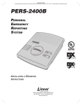
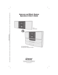
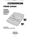
DESCRIPTION
MegaCode Series
MDT, MDT-2, MDT-4
DIGITAL TRANSMITTERS
Installation Instructions
MDT
(800) 421-1587 • www.linearcorp.com
INSTR,INST,MDT SERIES
Linear P/N: 207779 D
Material: 20 Lb. Mead Bond
Size: 8.500" x 11.000"
Ink: Black
Scale: 1-1
Side 1 of 2
STEP 1 Receiver Installation. Connect the receiver to the
garage door operator as described in the receiver’s Installation
Instructions. Apply power to the operator before programming.
The MegaCode series of digital transmitters are wireless radio controls
designed for use with automatic garage door and gate openers. The
MegaCode radio format provides unparalleled security. The system
can be programmed to more than a million different codes.
MegaCode transmitters and receivers do not contain a typical “coding
switch” as in Linear’s standard digital receivers. Each transmitter is
pre-set at the factory to a unique code. The receiver is programmed by
sending a signal to it from the transmitter(s) that are going to be used
with it. This stores the transmitter’s code into the receiver’s memory.
The receiver will retain its memory even without power. The receiver
will activate only from these “memorized” transmitters. Please refer to
the receiver’s instructions for maximum transmitter capability.
The transmitters are powered from two Type 2032 lithium “button cell”
batteries. When the batteries get low, the bright red LED light on the
transmitter will start to dim as the unit is activated. When the red LED
no longer lights when the transmitter is activated, the batteries should
be replaced.
STEP 2A MDR/MDRNR/MDR2 Program button and LED
Location. Locate the program button and LED on the side of the
receiver case.
CHANNEL ONE
PROGRAMMING
BUTTON
MDT - Single-channel transmitter with a button on the front and the
top (both buttons perform the same function).
MDT-2 - Three-channel transmitter with two buttons on the front and
one button on the top (each button performs a separate function).
MDT-4 - Five-channel transmitter with four buttons on the front and
one button on the top (each button performs a separate function).
MDT
MDT-2
MDT-4
STEP 2B M D R M / M D R M 2 P r o g r a m b u t t o n a n d L E D
Location. Locate the program button and LED on the back of the
receiver case.
C H A N N E L O N E
P R O G R A M M IN G
B U T T O N
PROGRAMMING
LED
CHANNEL TWO
PROGRAMMING
BUTTON
CONNECT RECEIVER TO GARAGE DOOR OPERATOR
STEP 3 Program receiver. Momentarily press the receiver’s
program button (channel one or two). The red programming LED
will light if there’s room in the receiver’s memory for another
transmitter. The LED stays on for about 5 seconds. A transmitter
must be entered while the LED is on. Press the desired
transmitter button. The LED will flicker indicating that the receiver
has accepted the transmitter.
➥ NOTE: Be sure to press the receiver program button for less than
2 seconds.
➥ WARNING! Door operator will not activate when the receiver
is being programmed from the transmitter, but the door
operator will activate the next time the transmitter is activated
after programming.
➥ NOTE: The programming LED also monitors radio signals entering
the receiver. It is common to see an occasional blink from the LED.
The LED will also light when any transmitter tuned to the receiver’s
frequency (programmed into the receiver or not) is activated.
WHEN RECEIVER
IS READY, PRESS THE DESIRED
TRANSMITTER BUTTON
C H A N N E L T W O
P R O G R A M M IN G
B U T T O N
P R O G R A M M IN G
L E D
STEP 4 Add additional transmitters. Repeat Step 3 for each
transmitter used with the receiver. Be sure to press the receiver’s
program button each time a new transmitter or a different
transmitter button on a multi-button transmitter is pressed.
If the LED doesn’t come on when the receiver’s program button is
pressed, the receiver’s memory is full. Use the erase function (Step 7)
to remove transmitters form the receiver’s memory.
CH 1
CH2
CHANNEL 1
PROGRAMMING
BUTTON
CHANNEL 2
PROGRAMMING
BUTTON
LED WILL LIGHT
WHEN RECEIVER
IS READY
RECEIVER LED
WILL FLICKER
AS TRANSMITTER
IS ENTERED INTO
MEMORY
CH1
CH2
THEN PRESS TRANSMITTER BUTTON
WITH MULTI-BUTTON
TRANSMITTERS PRESS
THE DESIRED BUTTON
PRESS CHANNEL 1 OR CHANNEL 2
PROGRAM BUTTON FIRST
STEP 5 Review memory. Press and hold the receiver’s
program button (channel one or two) until the LED begins to flash
(about 3 seconds) and then release the button. Count the number
of flashes. The number of flashes equals the number of
transmitters programmed into that channel of the receiver.
➥ NOTE: Don’t hold down the programming button longer than
5 seconds, the receiver’s memory for that channel will be
erased (Step 7).
STEP 6 Test receiver. Be sure door area is clear. Activate
each transmitter. The receiver relay should click (relay output
models only) and the operator should activate. Wait 2 seconds
between each activation.
STEP 7 Erasing receiver memory. Transmitters may be
erased from the receiver’s memory by pressing and holding the
receiver’s program button (channel one or two) for 5 seconds or
more. After the LED blinks (count of transmitters) it will blink one
more time for channel one and twice for channel 2 as the
receiver’s memory for that channel is erased. All transmitters
for each receiver channel are erased at the same time.
CH1
CH1
CH2
CH1
CH2
CH2
CH1
CH2
PRESS PROGRAM BUTTON
(CHANNEL 1 OR 2)
FOR THREE SECONDS
THEN RELEASE
WARNING!
BE SURE DOOR
AREA IS CLEAR
OF OBSTRUCTIONS
LED WILL FLASH, COUNTING THE
TOTAL NUMBER OF TRANSMITTERS
PROGRAMED TO THAT CHANNEL
INFO 1A Opening battery compartment. To access the
transmitter’s batteries remove the battery access screw on the
back of the unit. Flip the unit over so that the front is facing you.
Use a small screwdriver to open the battery compartment.
FLIP
TRANSMITTER
OVER
INSTR,INST,MDT SERIES
Linear P/N: 207779 D
Material: 20 Lb. Mead Bond
Size: 8.500" x 11.000"
Ink: Black
Scale: 1-1
Side 2 of 2
REMOVE BATTERY
ACCESS SCREW
PRESS TRANSMITTER
BUTTON TO TEST
INFO 1B Replacing transmitter batteries. Replace the two
batteries with two Type 2032 lithium batteries or equivalent. The
batteries stack on top of each other with the (+) sides facing the
front of the transmitter. Replace with new batteries then close the
battery compartment, replace battery access screw and test
transmitter.
REPLACE
WITH TWO
TYPE 2032
BATTERIES
PRESS PROGRAM BUTTON
(CHANNEL 1 OR 2)
FOR FIVE SECONDS OR MORE
LED WILL FLASH, COUNTING THE
TOTAL NUMBER OF TRANSMITTERS
PROGRAMED TO THAT CHANNEL.
THEN IT WILL BLINK ONE MORE TIME
AS THE TRANSMITTERS ARE ERASED
FROM THAT CHANNEL
INFO 2 Visor Clip Removal. The visor clip can be removed
by removing the three screws as shown. Slide the clip off the
retaining plate and reattach the plate to the transmitter.
REMOVE VISOR CLIP
BY REMOVING THREE
SCREWS
SIDE UP
32
20
SWING BATTERY
COMPARTMENT OPEN
➥ NOTE: The same transmitter (or the same transmitter button on
multi-button transmitters) cannot be programmed into both
receiver channels 1 and 2.
➥ NOTE: If the receiver’s LED flashes continuously when a
transmitter isn’t being activated, the receiver is too close to an
electrical noise source. Move the receiver away from the noise
source or call technical services for assistance.
CH1
CH2
CONTINUOUSLY FLASHING LED MAY
INDICATE ELECTRICAL NOISE
INTERFERRENCE
LIMITED WARRANTY
IMPORTANT !!!
This product is warranted to the consumer against defects in material and
workmanship for one year from the date of purchase. This warranty applies
to first retail buyers of new devices. Warrantor will repair, or at its option,
replace, any device it finds that requires service under this warranty, and
will return the repaired or replaced device to the consumer at the
warrantor’s cost. For warranty service and shipping instructions contact
warrantor at the address shown below. Devices must be sent to warrantor
for service at owner’s expense. The remedies provided by this warranty
are exclusive. Implied warranties under state law are to the one year period
of this written warranty. Some states do not allow limitations on how long
an implied warranty lasts, so the above limitation may not apply to you. In
order to be protected by this warranty, save your proof of purchase and
send copy with equipment should repair be required. This warranty gives
you specific legal rights, and you may also have other rights which vary
from state to state.
All products returned for warranty service require a Return Product
Authorization Number (RPA#). Contact Linear Technical Services at
1-800-421-1587 for an RPA# and other important details.
Linear radio controls provide a reliable communications link and fill an
important need in portable wireless signaling. However, there are some
limitations which must be observed.
✶ For U.S. installations only: The radios are required to comply with FCC
Rules and Regulations as Part 15 devices. As such, they have limited
transmitter power and therefore limited range.
✶ A receiver cannot respond to more than one transmitted signal at a time
and may be blocked by radio signals that occur on or near their operating
frequencies, regardless of code settings.
✶ Changes or modifications to the device may void FCC compliance.
✶ Infrequently used radio links should be tested regularly to protect against
undetected interference or fault.
✶ A general knowledge of radio and its vagaries should be gained prior to
acting as a wholesale distributor or dealer, and these facts should be
communicated to the ultimate users.
Copyright © 1999 Linear Corporation
207779 D