1
Owner's Manual
Manual
del Propietario
®
ROOM AI CONDITIONER
ACONDICiONADOR DE AIRE DE VENTANA
Model,
Modelo
Sears, Roebuck
www.sears.com
580. 72089
and Co., Hoffman
Estates,
IL 60179 U.S.A.
TABLE OF CONTENTS
WARRANTY
SAFETY
Features ................................................................
10
..............................
2
..............................................................
2
................................
10
Display ........................................................... t 1
3
....................................................................
Using the Air Conditioner
Remote Control ..............................................12
important Safety instructions .............................
3
ELECTRICAL
INSTALLING
REQUIREMENTS
THE POWER
MAINTENANCE
........4
CORD
Air Filter Cleaning .........................................13
4
Air Conditioner
INSTALLATION
installation
...............................................
13
Cleaning ........................... '13
.........................................................
5
How to Remove the Front Grille .........................
13
Requirements
...............................5
How to Replace the Front Grille ......................13
installation .................................................................
6
TROUBLESHOOTING
.........................................
14
How to Install .......................................................
6
Before Calling for Service ......................... 14
Removal from Window ..............................................
8
OPERATION
REPAIR
....................................................................
9
PARTS
..........................................
16
How and Why ...................................................................
9
Normal Sounds
g
.............................................................
SERVICE
NUMBERS
...............
Back Cover
Capacity and Running Time ........................ 9
FULL ONE YEAR WARRANTY
ROOM AIR CONDITIONER
WARRANTY SERVICE lS AVAILABLE
CONTACTING
SEARS SERVICE AT
1-800-4-MY-HOME_o
ON
For one year from the date of purchase, when this
air conditioner is operated and maintained for
normal room cooling according to instructions in this
owner's manual, Sears will repair this air
conditioner, free of charge, if defective in material or
workmanship..
FULL FIVE-YEAR WARRANTY ON
SEALED REFRIGERATION SYSTEM
BY
Warranty coverage applies only to air conditioners
used for non-commercial, private household
purposes.
This warranty applies only while this product is in
use in the United States
This warranty gives you specific legal rights, and
you may also have other right which vary from state
to state.
For five years from the date of purchase, when this
air conditioner is operated and maintained for
normal room cooling according to instructions in this
owner's manual, Sears will repair the sealed
refrigeration system (consistingof refrigerant,
connecting tubing, and compressor), free of charge,
if defective in material or workmanship..
_2_
Sears, Roebuck
and Co., D/817WA,
Hoffman
Estates,
IL 60179 U.S.A.
iMPORTANT
SAFETY INSTRUCTIONS
The safety instructions below will tell you how to use your room air conditioner to avoid harm to yourself or
damage to your ROOM AIR CONDITIONER.
FOR YOUR SAFETY
Do not store or use gasoline or other flammable
vapors and ]iquidsin the vicinity of this or any other
appliance.. Read product labels for flammability and
other warnings.
_
PREVENT
Avoid fire hazard or electric shock..
Do not use an extension cord or an adapter plug..
Do not remove any prong from the power cord..
Grounding type
wall rece
ACCIDENTS
To reduce the risk of fire, electrical shock, or injury
to persons when using your air conditioner, follow
basic precautions, includingthe following:
• Be sure the electrical service is adequate for the
model you have chosen..
• if the air conditioner is to be installed in a window,
you witl probably want to clean both sides of the
glass first.. If the window is a triple-track type with a
screen panel included, you may want to remove
the screen completely before installation..
• Be sure the air conditioner has been securely and
correctly installedaccording to the separate
installationinstructionsprovided with this manual
Save this manual and installation instructions for
possible future use in removing or reinstalling this
unit.
Do not, under any
circumstances, cut,
remove, or bypass
the grounding prong
from this plug.
Power suppfy cord _1,
with 3-prong
grounding plug
ENERGY SAVING IDEAS
• The capacity of the room air conditioner must fit
the room size for efficient and satisfactory
operation.
° Use g_oves when handling the air conditioner
Be careful to avoid cuts from sharp metal fins on
front and rear coils..
• Install the room air conditioner on the shady side
of your home.. A window that faces north is best
because it is shaded most of the day..
_ii_
• Do not block air flow inside with blinds, curtains, or
furniture, or outside with shrubs, enclosures, or
other buildings.
ELECTRICAL
INFORMATION
The complete electrical rating of your new room air
conditioner is stated on the serial plate. Refer to the
rating when checking the electrical requirements.
• Be sure the air conditioner is properly grounded
To minimize shock and fire hazards, proper
grounding is important.. The power cord is
equipped with a three-prong grounding plug for
protection against shock hazards.
oKeep blinds and drapes in other windows dosed
during the sunniest part of the day
• Clean the air filter as recommended in the
MAINTENANCE section of this manual
• Your air conditioner must be plugged into in a
properly grounded wall receptacle. If the wall
receptacle you intend to use is not adequately
grounded or protected by a time delay fuse or
circuit breaker, have a qualified electrician install
the proper receptacle..
° Proper insulation and weather stripping in your
home will help keep warm air out and cool air inl.
,, External house shading with trees, plants or
awnings will hetp reduce the air conditioner's work
load..
. Do not run air conditioner with a protective
covering. This could result in mechanical damage
within the air conditioner
,, Do not use an extension
plug.
. Close the floor and wall registers and the fireplace
damper so cool air does not escape up the
chimney and into the duct work.,
. Operate heat producing appliances such as
ranges, washers, dryers, and dishwashers during
the coolest part of the day
cord or an adapter
-3-
OBSERVEALLLOCALCODESAND
ORDINANCES.
_WARNING
DO NOT_UNDER ANY CIRCUMSTANCES_
REMOVETHEPOWERSUPPLYCORD
GROUND PRONG.
ELECTRICAL GROUND
THIS APPLIANCE.
A 115-vott 60 Hz,
properly grounded
A time delay fuse
is recommended.
IS REQUIRED
ON
AC only, 15A fused and
electrical supply is required,
or time delay circuit breaker
Use a dedicated circuit,
RECOMMENDED
GROUNDING
Shock Hazard
Plug into a grounded
3 prong outlet.
Do not remove ground prong.
Do not use an adapter,
serving only this appliance.
DO NOT USE AN EXTENSION
Electrical
CORD.
METHOD
For your personal safety, this appliance must
be grounded° This appliance has a power
supply cord with a 3-prong grounding plug° To
minimize possible shock hazard, the cord must
be plugged into a mating grounding type walt
receptacle and grounded in accordance with
the National Electrical Code (ANSI/NFPA 70)
latest edition and all local codes and
ordinances, if a mating wall receptacle is not
available, it is the personal responsibility and
obligation of the customer to have a properly
grounded 3-prong wall receptacle instaifed by a
qualified electrician°
Do not use an extension
cord_
Failure to follow these instructions
can result
in death, fire, or electrical shock.
3-prong ..._
grounding _"
0,u0
N
¢]
Power
supply
cord
J
grounding
type wall
receptacle
, _p
Ground
prong
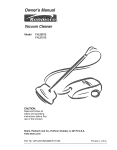
You can choose between two methods below according to your window stoot shape and preference.,
USING SLIT "A"
Fasten the stopper using 2 screw holes, and lead
out the power cord throughslit "A",
USING
SLIT
"B"
Fasten the stopper using left screw hole, and rotate
properly to lead the power cord out through slit "B"
:i
Power
:
!
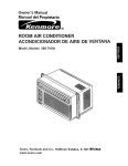
INSTALLATION
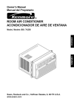
INSTALLATION REQUIREMENTS
HARDWARE
Your air conditioner wil! instalfinto standarddouble hung
windowswith actuatclear openingwidths of 25 to36
inches (635mm to 914rnrn)(FIG t)
Lower sash must open sufficiently to allow a clear
vertical opening of 15 inches (381mm). Side louvers
and the rear of the air conditioner must have clear
air space to allow enough airflow through the
condenser for heat removal. The rear of the unit
must be outdoors, not inside a building or garage.
i /"--
Sash
25" tO 36" _lit
t5 rain ]nner silt_ J j--"
I I
.-"1_1,./--
lnleriorwall
"'-J
1""
Window
Offset
FIG. "t
FIG, 2
ELECTRICAL
SERVICE
Check your available electrical service. The power
supply available must be the same as that shown
on the unit nameplate (found on right side of cabinet)
ITEM
All models are equipped with a 3-prong service plug
to provide proper service and safe positive
grounding., Do not change ptug in any way Do not
use an adapter plug. If your present wall outlet does
not match your plug, call a qualified electrician to
make the necessary corrections,
SAVE CARTON and this OWNER'S MANUAL for
future reference. The carton is the best way to store
unit during winter or when not in use.
A
NAME OF PARTS
SiDE CURTAIN
B
SILL SUPPORT
C
BOLT
LOCK NUT
D
E
F
G
SCREW:
sCREW:
25/64"
5i8"
SCREW:
5/8"
-5_
2
2
13
3
FOAM STRIP
5
1
I
J
FOAM SEAL
1
L BRACKET
1
TOOLS:
"Tight Fitting gloves
• Standard screwdriver
., PhiIlips screwdriver
• Pliers
. Sharp knife
• 3/8-inch open end wrench or adjustable
• 1/4-inch hex socket and ratcher
• Tape measure
,, EIectfic drill
,, 1/4-inch drill bit
° Make sure air conditioner does not fall during
installation.
2
2
H
REQUIRED
To avoid risk of personal injury, property damage,
or product damage due to the weight of this
device and sharp edges that may be exposed:
• Air conditioners covered in this manual pose an
excessive weight hazard Two or more people
are needed to move and install the unit,
To prevent injury or strain, use proper lifting and
carrying techniques when moving unit.
• Carefully inspect location where air conditioner
will be installed, Be sure it will support the
weight of the unit over an extended period of
time.
• Handle air conditioner with care. Wear
protective gloves whenever lifting or carrying the
unit.,AVOID the sharp metal fins of front and
rear coils.
Q'TY
wrench
INSTALLATION
Upperguide
Pick a location which will allow you to blow the cold
air into the area you want.. Windows used for
installation must be strong enough to support the
weight of the air conditioner. Good installation with
special attention to the proper position of the unit
will lessen the chance that service wilt be needed.
ITEM E
L
When cooling more than one room, installation
locationis very important, To cool your rooms, cold
air must be blown from the air conditioner in a
straight path.
_Open
the window
window inner sill.
HOW TO INSTALL
tf the air conditioner is blocked by a storm window frame,
see step 19 on page 8 before beginning to install
D
Remove the screws which fasten the cabinet at
both sides and at the back. Save side screws.
Discard back screws.
Mart{ a line on center of the
Carefully place the cabinet on the window inner sill
and align the center of the cabinet front with the
center tine marked in the window inner silt.
:
_Window
sill
FIG. 7
FIG. 3
_
Slide the unit out of the cabinet by gripping the
base pan handle and pull forward while bracing the
cabinet.
_Pull
the bottom window sash down behind the
upper guide until they meet.
NOTE: Do not pull the window sash down so tightly
that the movement of side curtain is restricted,,
Window sash
Upper guide
Foam
seal"
Side curtain
FIG. 4
_Cut
the FOAM SEAL (ITEM l) to fit the
underside of the window sash. Peel off the backing
and attach the FOAM SEAL as shown in Fig 5,
_
Loosety assemble the sill supports using the
parts in FIG. 9.
FIG. 5
,.ooo,
o. oo
"_
_
Insert the side curtain (iTEM A) into the upper
guide and lower guide of the air conditioner,, Fasten
the curtains to the unit with screws (ITEM E)
f/ITEM C
ITEM g
'_--u
'" _TEMD
FIG. 9
Q Select the position that wilt place the sill supports
near the outermost point on sill (FIGo 10)
Attach the sill supports to the cabinet track hole
closest to the selected position using screw (ITEM E).
Lower guide
, ,, _.
_,
_] Attach the L BRACKET (ITEM J) with screw
(ITEM G)., (FIG, 14)
/ ]II ,TEM
_&
_
'
/
FIGo 14
'N
CaNnel
_]
DRAINAGE
Be sure to insertthe drain pipe into base pan before
installation.,
The air conditioner must be installed with a slight tilt
downward to the outside for proper water drainage°
The air conditioner will drain the excess condensed
water through the drain pipe (FIG, I5)
_
Place the sill supports with the cabinet on the
window sill's selected position
_ti]
The cabinet
should be installed with a very
slight tilt (about 1/4") downward
(FIG 11),,
toward the outside
Adjust the bolts and the nuts of sill supports
the cabinet.,
DRAINp_BASE
to level
'-'-In.,,_
PAN REAR
BASE PAN BOTTOM
FIG. 15
_
J
_
_-----TEMB
fo
FIG. 11
Slide the chassis into the cabinet. (FIG. 16)
CAUTION: For security purposes, reinstall side
screws you removed in step I.
[_r
_
Attach the cabinet to the inner sill by driving the
screws (_TEM F) through the front angle into the
window inner sill (FIG, 12),,
i I:I Ir
Screw
"_,,_
Screw
FIGo 16
_Cut
the foam strip (ITEM H) to the proper length
and insert between the upper window sash and the
lower window sash,, (FIG, 17)
I_
. -- Lower Guide
tTEM F
ITEMB
[]Pull
FIG. 12
each side curtain fully to each side of
FIGo 17
window opening
Attach each side curtain to the window sash using
screws (ITEM G). (FIG, 13)
_The
vent control handle must be straightened
before the decorative front is attached
Putl out part @ to align with part (_.
ITEM G
.Part(
FIG. t8
FIG. 13
-7_
_
FRONT INSTALLATION
Top of wood strip should be approximately 3/4"
higher than the storm window frame to help
condensation to drain properly to the outside
• Install a second wood strip (approximately 6" long by
1V2"wide and same thicknessas first strip) in the
center of the outer sill flush against the back of the
inner sill Screw the L brackets into thisstrip
This will raise the L bracket as shown in F1G 22,
Install the front grille(packed separately) onto the
cabinet as follows:
• Hook upper tabs of front grille into slots on the
cabinet top° (FIG, 19)
o Push front gritle's tips towards the cabinet in order
to snap side tabs into the cabinet, (FIG,, 19)
• Open the inlet grille., (FIG, 20)
• installthe screw (ITEM E) through the front grille.
(FIGo 20)
oCtese inlet grille. (FIG.,21)
1 1/2" min
WOOD STRIP MOUNTED
ON TOP OF INNER S_LL
(38ram)
__
--_-
_L,
J"
INNER
]
4 _
]L BRACKET
INSIDE
_
3/4"
CLEARANCE V
WINDOW
I FRAME
J
J OUTER
l
I S LL
1
OUTSIDE
FIG, 22
Front lnstaflation
Front Installation
Front installation
REMOVAL
FIG, 19
FROM WINDOW
• Turn off and unplug the air conditioner
. Remove the front grille, See HOW TO REMOVETHE
FRONT GRILLE Referto page 13
. Unscrew the sidescrews that you installed in Step 15
• Slide the air conditionerout ef thecabinet,
BE CAREFUL NOT TO DROP IT, Held onto it firmly the
whole way slidingit out Once removed,set it safety out
of the way
- Remove the L bracketfrom window frame and the sash
seal from betweenthe windows
• Unscrew the sidecurtainsfrom the window frame Fold
themback to thesides of the cabinet
=Remove screws attachingcabinet to inner sill Be careful
not te tot cabinet fall once screws are removed
• Removecabinet from windowopening,
• Place air conditionerinto cabinet Reinstallside screws
and Front Grille
• Place unit and all assemblyhardwarein air conditioner
shippingcarton, and store in clean, dry place
_.t
FIG. 21
_IF
AIR CONDITIONER IS BLOCKED BY
STORM WINDOW FRAME
, If storm windowpresents interference, fasten a 2'*
wide wood strip to the inner window sill across the full
width of the sill The wood strip should be thick
enough to raise the height of the window silt so that
the unit can be installedwithout interference from the
the storm window frame. See FfG 22
-8-
° Air conditioners covered in this manual pose an
excessive weight hazard. Two or more people
are needed to move and install the unit.
To prevent injury or strain, use proper lifting and
carrying techniques when moving unit
• When handling the air conditioner, be careful to
avoid cuts from sharp metal fins on front and
rear coils,,
• Make sure air conditioner does not fall during
removal.
HOW AND WHY
Your room air conditioner provides the following
functions to make hot weather living more
comfortable:
-- Compressor
The modern high efficiency
compressor may have a high
pitched hum or pulsating
noise that cycles on and off.
• Cools and circulates room air..
° Lowers humidity by removing excess moisture..
• Filters out summertime dust, dirt, and some
airborne impurities.
-- Unit Vibration
The air conditioner performs these functions by
drawing room air through a filter which traps dust
and dirt particles. The air then passes over a
cooling coil which refrigerates the air and removes
excess moisture. The same air is then returned to
the room- cooler, dder, and cleaner. Moisture
removed from the room air is carried to the outside
and evaporated..
The unit may vibrate
and make noise
because of poor wall
or window construction..
Fan
You may hear air
movement from
the fan.
Your air conditioner is designed to be easy to
operate and to provide plenty of cooling power.
NORMAL
SOUNDS
FIG. 23
Aside from the regular fan motor and compressor
sounds coming from your air conditioner, you will
once in a while hear a pinging sound. This is the
result of moisture being picked up from the air in the
room and thrown against the air conditioner's fen.
This is normal and should not be cause for concern..
Also, do not be alarmed if you hear a slight hissing
or gurgling sound coming from your air conditioner
after it is off,. These are normal coolant noises.
You may hear droplets of water hitting
the condenser causing a pinging or
clicking sound..
FIG,
CAPACITY AND RUNNING TIME
Proper unit size is importantin deciding the desired
comfort for the area you want to cool..An
undersized unit will not have the capability to cool,
leaving the area uncomfortably warm. The proper
size is determined by the number of square feet in
the area to be cooled, indoor and outdoor
temperature and humidity.
Whenever the heat or humidity load is above normal
the air conditioner must run longer and more often
to keep the desired temperature you have selected,
Under heavy heat load conditions the air conditioner
may need to run constantly to keep the temperature
you want
At times using the MED FAN setting to circulate the
room air may make it comfortable even though the
air is not being cooled, This will decrease your cost
of use.
-9-
23
USING THE AIR CONDgTIONER
FEATURES
r!'_i_-[_
TO reduce the risk of fire, electric
shock, or injury to persons, read the important
SAFETY instructions section before operating this
appliance
To begin operating the air conditioner
installation, follow these steps:
after
1. Plug in the air conditioner. (To prevent electrical
hazards, do not use an extension cord or an
adapter plug..)
2. Set the exhaust vent to the CLOSE position..
3. Set the TEMP Control to the coolest setting.,
4 Set the MODE control at the highest COOL level
5. Adjust the louvers for comfortable
32714
6 5
air flow.
6 Once the room has cooled, adjust the TEMP and
Mode Control to the setting you find most
comfortable
NOTE : If the air conditioner is turned off, wait 3
minutes before restarting.. This allows pressure
inside the compressor to equalize. Failure to wait 3
minutes before restarting may cause inefficient
operation
if you move the TEMP Control to a warmer, then
immediately back to a cooler setting, the unit will
shut off. Wait 3 minutes before restarting.
18
179
8
I3
16
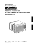
FIG.
1 Cabinet
2o Vertical Air
Direction Louvers
3, Horizontal Air
Direction Louvers
4. inlet Grille
5o Air Filter
6. Front Grille
7 Control Board
8 Power Cord
9, Evaporator
10o Condenser
VENT CONTROL
The Vent Control allows the air conditioner to
either recirculate inside air (CLOSE) or exhaust
air to the outside (OPEN) (FIG 25)
- The CLOSE position is used when maximum
cooling is desired It may also be used for air
recircuration without cooling when the air
conditioner is set in the FAN positiOn,r
"The OPEN position removes stale air from the
room and exhausts it to the outside Fresh air is
drawn into the room through your home's
normal air passages,,
,, The OPEN or CLOSE position can be used with
any fan selection,
24
Coil
t 1 Compressor
12 Base pan
- 13 Brace
14 Upper Guide
15., Curtain
16 Remote Control
17 Air Purifying
18 Case, Filter
Filter
PULL
OPEN
/ PUSH
CLOSE
FgG. 25
-10-
DISPLAY
FAN SPEED
• Every timeyou push this button, it advancesthe setting as follows: {High-, Low -, Med-, High}
/r__-'_-;_
_
_-"
--
REMOTE
SIGNAL
PbAS MAire
"
(.MODE
_'-_NQ
_
_
;
po_
[
RECEIVER
f- POWER
| o To turn theair conditionerON,
|
push the button.To turnthe
air conditionerOFF,push
the button again
- This buttontakespriorityover
any otherbutton
._-
.___
CONTROL
_
air conditioneris on the
. Whenyoufirst turn it on, the
Highcool modeand theTemp
at 72°F
TEMPERATURE
SETTING
- Every time you push this button, it willshift among
• This button can automaticallycontrol
COOL, ENERGY SAVER and FAN
the temperature of the room
- ENERGY SAVER:
The temperature can be set within a
range of 60°F to 86°F by increments of I°F
• The fan stops when the compressor stops cooling
Approximately every 3 minutes the fan will turn on and
check the room air to determine if cooling is needed
TIMER
- SHUT-OFF TIME
• If unitis running,Timer setsnumberof hoursuntilshut-off
, Everytime you pushTimerbutton,it advancestheTimersettingas follows:1 Hour_*2 Hours.....
12 Hoursmaximum
- STARTTIME
• If unitis off, Timer setsnumberof hoursbeforeunitstarts
• Everytime youpush Timerbutton,it advancestheTimersettingas follows:1 Hour_,2 Hours.....
HORIZONTAL
AIR DIRECTION
CONTROL
The horizontal air direction is adjusted by moving
the vertical louvers right and teft with your
fingertips, (FIG 26)
12 Hoursmaximum
VERTICAL AIR DIRECTION CONTROL
The vertical air direction isadjusted by moving the
horizontal louvers up and down with your fingertips,
(FIG,. 27)
%
FiG. 27
REMOTE
CONTROL
NOTE: The Remote Control will not operate properly if strong light shines on the sensor window
Conditioner or if there are obstacles between the Remote Control and the Air Conditioner,,
of the Air
Every time you push button, you will hear a beep from the Air Conditioner°
POWER
• To turn the air conditioner ON, push the button To turn the air conditioner OFF,
push the button again This button takes priority over any other button
When you first turn it on. the air conditioner is en the High cool mode and the Temp
at 72=F
AIR PURIFIER .........
Press the Air Purifier button Operation witl start at low speed when the button is pressed
and stop when the button is pressed again
• Set the fan speed with lhe remote control
• You can select Air Purifier function without cooling
Increase fan speed by pressing Fan Speed button
TEMPERATURE
|
|
"..-
Fan speed will at first be low
SETTING
• This buttoncan automatically control the temperatureof lhe room
The temperature can be set within a rangeof 60°F to 86°F by increments of I°F
FAN SPEED
SLEEP
MODE
• Every time you push this button it advances the setting as follows:
{High -. Low -* Med -, High}
SLEEP MODE
• Press the Sleep button to set the time you want the unit to turn off automatically
• For your sleeping cernfort, once Timer is set. the Temperature setting will raise by 2F
after 30 min, and 2"F after another 30 min
. Every time you push this button, the remaining time will be set as follows
(1Hour -, 2Hours -, 3Hours . 4Hours , 5Hours . 6Hours
. 7Hours
-, 1Hour., 2Hours -. )
-, 0Hours
TIMER
\
- SHUT-OFF TIME
• tf unit is running, Timer sefs number of hours unW shut-off
• Every time you push Timer button, [t advances the Timer setting as follows: 1 Hour--
2 Hours --_
-' 12 Hours maximum
- START TIME
• It unit is off, Timer sets number or hours before unit starts
', Every time you push Timer button, it advances the Timer setting as fotlows: 1 Hour _ 2 Hours
MODE
•
4. t2 Hours maximum
--
- Every time you push this button, it witt shift among COOL. ENERGY SAVER and FAN
- ENERGY SAVER
,, The fan stops when the compressor stops cooling
Approximately
every 3 minutes lhe fan will turn on and check the room air le de,ermine if coo}ing is needed
HOW TO iNSERT
BATTERgES
D
the back
emove the cover
remote controller,
from
of the
insert two batteries.
° Be sure that the (+) and (-) directions
are correcL
° Be sure that both batteries are new
_
Re-attach
" Do not use rechargeabte
Such batteries
batteries
differ from standard dry cells in
shape, dimensions, and
performance,
_)
the cover.
-12-
- Remove the batteries from the
remote controller if the air
conditioner is not going to be used
for an extended length of time°
AiR FILTER
CLEANING
To ensure continued peak efficiency, the condenser
coils (outdoor side at the unit) should be checked
periodically and cleaned if they become clogged
with soot or dirt from the atmosphere. Brush or
vacuum exterior coils to remove debris from fins.
The Air Filter will become dirty as it removes dust
irom the inside air tt should be washed at least
every 2 weeks tf the Air Fiiter remains full of dust,
the air flow wi!t decrease and the cooling capacity
wifl be reduced, possibly damaging the uniL
,, Pull the inlet grille forward, grasping both tabs,
then pull out the air filter (FIG, 28)
o Wash the Air Filter under the faucet with warm
water Be sure to shake off aIi the water before
replacing
the filter
FIG.
31
(FIG 29)
HOWTO REMOVE THE FRONT GRILLE
• Open the inlet grille downward,
o Remove the screw securing
the Front Grille
• Push the grille up from the bottom and pull the top
of the griile away from the case to lift the top tabs
out of their slots.
,I
FIG.
28
FiG.
29
AiR PURiFYiNG FILTER CLEANING
//_
CAUTION:
To touch
avoid Air
possible
minor
electric
shock,
do not
Purifying
Filter
within
10 seconds after opening inter grille,
The Air Purifying filter behind the air filter should be
checked and cleaned once every 3 months or more often
if necessary
,, After removing the air filter, pull Air Purifying filter
slightty fop._ard to remove
• Dip the Air Purifying fitter into water mixed with neutral
detergent for 20_.30 minutes
o The Air Purifying Filter must be completely dry before
reinstalling it into the Air Conditioner
,, Re-install the Air Purifying filter to the original position
HOW TO REPLACE
FRONT GRILLE
: ":
Attach the front grilie to the cabinet by inserting the
tabs on the grille into the slots on the front of the
cabinet. Push the grille in until it snaps into place.
';,:3 "
AnR CONDUT ONER
THE
CLEANnNG
Clean the front grille and inlet grille by wiping with a
cloth dampened in a mild detergent solution
The cabinet may be washed with mild soap or
detergent and lukewarm water, then polished with
liquid appliance wax
FIG,
-13-
33
BEFORE CALLING FOR SERVICE
Check the following list to be sure a service call is realty necessary
help you avoid an unneeded service call
THE AIR CONDITIONER
Check
A quick reference
to this manual may
WILL NOT OPERATE
Then...
if,..
Wail plug disconnected.
House fuse bbwn or circuit breaker t_iDPed.
Poweris OFF.
Unitwas turnedoff and lhen on too quickly.
TEMP Controlset warmer lhan roomtemperature.
_ ush p!ug firmlyinto wail outlet.
Replaceluse with time dela2/_lypeor resetcircuit breaker.
Pushthe Powerbutton:
L Set unit off and wait3 minutes beforerestarting_
I Set TEMP Controlto lower temperature.
AIR FROM UNIT DOES NOT FEEL COLD ENOUGH.
Check
Then...
if,..
FAN SPEED set at LOW.
TEMP Control settoowarm.
Roomtemperature below70'_F(2t°C).
Temperaturesensingtubetouchingevaporatorcoil.
locatedbehind front gdlle
t Push FAN SPEED buttonto set at HI.
_Cooling may not occur until room temperaturerisesabove 70=F(21°C).
away
evaporalercoil
I Straighlen
Set TEMP tube
Control
to afrom
lower
lemp_erature.
THEAIRCONDITIONER
COOUNG,
BUTROOMISTOOWARM- ICEFORMING
ONCOOLING
COILBEHINDFRONTGRILLE.
Check if..,
Then...
Outdoor temperaturebetow70_F(2t _C)
To defrostthe coil,set the MODE to FAN
Air filtermay be dirty
Clean air filter, Referto Maintenancesectionof owner'smanual
TEMP Controlset too cold lot night-timecooling
.............Todeirostthecoil.sel the MODE to FAN or "High Coot"with'ihe......................
TEMPcontrolto hiqhertemperature.
THE AIRCONDITIONER
COOLING,BUTROOMIS TOOWARM.
Check if...
Then...
TEMP Controlset toowarm,
Frontof unit is blockedby drapes,blinds,furniture,etc
Air distributionis restricted,
I Dirtyair
filter- air restricted, open. Cotd air escapes,
Doors,windows,registers,etc.
Unitrecentlyturnedon in hot _oom
THE AIR CONDITIONER
Check if...
TURNS
WHEN
if...
UNIT
Clean
air filter.Refer to registers,etc.
Maintenancesectionof owner's manual.
Closedoors,windows,
Allowadditionaltimeto removestoredheattromwails,ceiling,floor,andfurniture,
ON AND OFF RAPIDLY.
Then...
I Outside temperatureis extremely hot
NOISE
Check
Set TEMPControl to lower temperature.
Clearblockage in front el unil
t Set FAN SPEED on HI to brfngair past coolingceils faster
]
tS COOLINGo
Then..
I W__
Soundof fan hittingwaterItemthemoistureremovalsystem, This
is normalwhen
humidityis high.Closedoors,windows,and
registers,!
Referio
installationinsi_ctions
or Checkwith installer.
WATER DRIPPING
Check if,..
INSIDE
ROOM
WHEN
! The air c°nditi°ner is impr°perlyinstalled
WATER DRIPPING
Check if...
OUTSIDE
WHEN
The unit is removinglargequantitiesof moisture
from humid room
UNIT IS COOLING.
Then...
I t°linstatlafion
Tilt air c°nditi°ner
instructionsor
slightlyt°
check
the°utside
withinstaller
t° aii°w water drainage Refer
UNIT IS COOLING.
Then...
] This is normalduring excessivelyhumid days
L
-14-
-!5-
Room Air Conditioner
To order' Parts call Toll Free
Model No. 580.72089200
CAUTION:
1-800-4-MY-HOME
Use the Kenmore
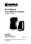
CABINET
part number
& FRONT
on all orders,
GRILLE
3-A
6-A
5-A
1-A
12/01
- 16-
(1-800-469-4663)
not the illustration
ASSEMBLY
number.
580 72089200
CAUTION:
Use the Kenmore
CABINET
ILLUSTRATION
part number
& FRONT
on all orders, not the illustration
GRILLE
number
ASSEMBLY
PART NUMBER
DESCRIPTION
1 _A
3530A20043A
FRONT
2-A
3530A20046A
INLET GRILLE
3 _A
5231A20006A
AIR FILTER ASSEMBLY
4-A
4458A20019A
VANE
5 -A
4758A20016A
LOUVER
6 -A
4758A20016B
LOUVER
7 -A
3091AR2317J
CABINET
8 -A
4974AR3328C
UPPER GUIDE
9-A
3850A20242S
LABEL, ENERGY
3828A20133P
MANUAL OWNER'S
NUMBER
# = Functional
GRILLE
ASSEMBLY
Parts
* = Non-illustrated
Parts
17 -
12/01
580 72089200
CAUTION:
Use the Kenmore
part number
CONTROL
IO-B
9-B
_
on all orders, not the illustration
number,,
BOX ASSEMBLY
3-B
6-B
.......
w
7-B
14-B
2-B
13-B
15-B
t2/01
8-B
- 18 -
580,72089200
CAUTION: Use the Kenmore part number on all orders, not the illustration number,,
CONTROL
PART NUMBER
DESCRIPTION
4994A10029A
CONTROL
2-B
3720A10061A
PANEL CONTROL
3-B
3550A30114A
COVER CONTROL
4-B
6871A20167A
PWB ASSEMBLY,
AC
5-B
6871A20168B
PWB ASSEMBLY
DC
6-B
6120AR2359V
CAPACITOR
7-B
6609A10003G
H,,V ASSEMBLY
6411A20011F
POWER CORD ASSEMBLY
9-B
6323A20004D
THERMISTOR
ASSEMBLY
10-B
6631AR3843U
CONNECTOR
ASSEMBLY
11 -B
6850A90001G
CABLE FLAT
12-B
6631A30003A
CONNECTOR
13-B
6601A30002A
SWITCH
ASSEMBLY
14-B
6711A20053B
REMOTE
CONTROL
15-B
3790A20021B
WINDOW
DISPLAY
ILLUSTRATION
NUMBER
I-
B
8-B
# = Functional
BOX ASSEMBLY
#
#
BOX
BOX
ASSEMBLY
Parts
* = Nonqllustrated
Parts
- 19 -
t2/01
580,72089200
CAUTION:
Use tl3e Kenmore
part number
AIR HANDLING
on atl orders, not the illustration
number.
& CYCLE PARTS
17-C
11-C
9-C
12-C
6"0
--
8-C
4-0
7-C
16-C
t5-C
19-C
12/01
- 20 -
580.,72089200
CAUTION:
Use the Kenmore
part number on all orders, not the illustration
AIR HANDLING
PARTS
PART NUMBER
DESCRIPTION
1-C
3041A20021N
BASE PAN WELD ASSEMBLY
2-C
5238A20007A
AIR GUIDE LOWER
3-C
4681A20027X
MOTOR
4-C
5900A20020A
FAN, TURBO
ILLUSTRATION
NUMBER
# = Functional
& CYCLE
number.
ASSEMBLY
I
5-C
#
3H02932B
CLAMP SPRING
6-C
#
4948A10014A
ORIFICE
7-C
#
5421A10026A
EVAPORATOR
8-C
4998A10012A
SHROUD
9-C
5900AR1167B
FAN
10-C
5403A20043M
CONDENSER
11-C
4800A30002A
BRACE
12-C
5238A20009A
AIR GUIDE UPPER
13-C
4900A20003A
VENTILATION
14-C
4H02023A
DRAIN RUBBER
15-C
4HO1029D
WASHER
16-C
3H02773A
DRAIN PiPE
17-C
3530A20009H
GRILLE ASSEMBLY,
18-C
3110A20042A
FILTER CASE
19_ C
5983A10009H
PLASMA FILTER ASSEMBLY
.lu
ASSEMBLY
S
S
l
ASSEMBLY
DAMPER
RUBBER
REAR
Parts
* = Non-illustrated
Parts
-21-
12/01
58072089200
CAUTION:
Use the Kenmore
part number on all orders, no__tt
the illustration
COMPRESSOR
©
8-D
number.
PARTS
" 9-D
Q
-}!
12-D
7-D
!3-D
6-D
_'
-10-D
5-D
2-D
11-D
4-D
3-D
1-o
12/O1
- 22 -
580 72089200
CAUTION:
Use the Kenmore part number on all orders, not the illustration
COMPRESSOR
ILLUSTRATION
NUMBER
PARTS
PART NUMBER
DESCRIPTION
4984AR4335A
ISOLATOR,
5416Ag0007A
COMPRESSOR
3 _D
4810AR4155B
BRACKET,
WASHER
4 - D
1NHA0801206
HEXAGON
NUTS
5 - D
4986A30001A
GASKET
6750A30001 N
OVERLOAD
7- D
3550A30048A
TERMINAL
8 -D
4H01058A
GASKET
9 -D
4H00947A
TERMINAL
10 - D
5211A10074D
TUBE ASSEMBLY
DISCHARGE
t1- D
5211A20228F
TUBE ASSEMBLY
SUCTION
12 - D
5211A20470B
TUBE ASSEMBLY
EVAPORATOR
13 - D
5211AR3332Y
TUBE ASSEMBLY
CONNECTOR
1- D
2 _D
6 - D
# = Functional
number°
#
#
COMP
PROTECTOR
COVER
NUT
COVER NUT
Parts
* = Non-ilJustrated
Parts
-23-
12/01
58072089200
CAUTION:
Use the Kenmore
part number
mNSTALLAT_ON
I
! 2/01
i
!,
on all orders, not the illustration
KIT ASSEMBLY
number,
580,72089200
CAUTION:
Use the Kenmore
part number
INSTALLATgON
ILLUSTRATION
NUMBER
# = Functional
on all orders, nott the illustration
number.
KBT ASSEMBLY
PART NUMBER
DESCRIPTZON
1- E
4959AR3402A
SIDE CURTAIN
ASSEMBLY
2 - E
4959AR3402B
SIDE CURTAIN
ASSEMBLY
3 -E
4810AR3240A
SILL SUPPORT
BRACKET
4 -E
1BHD1004006
BOLT
5 -E
1NHC1000006
NUT
6 - E
4HO1785B
L BRACKET
Parts
* = Non-itIustrated
Parts
- 25 -
12/01
INDICE DE MATERIAS
GARANT{A
................................................
SEGURIDAD
Ca_acte risticas
.............................. 26
26
....................................... 34
Uso del equipo de aire acondicionado
,34
Despliegue ............................................
Contro remoto ......................................
35
36
........................................................
27
MANTENIMIENTO
lmportantes instruccionesde seguridad .....27
....................................... 37
Limpieza del filtro de! aire .....................
REQUERIMIENTOS
ELI_CTRICOS
..........28
INSTALAClON
DEL CABLE ELECTRICA
INSTALAClON
................................................. 29
Umpieza del equipo de aire acondicionado .....37
C6mo sacar la rejitla frontal ...............
28
CSmo a reemplaza
CORRECClON
Requerimientos para instalaciOn ......... 29
InstaflaciSn ....................................................30
de la ventana ...............
DE FALLAS
....................
38
LISTA DE PARTES
....................................
16-25
32
PARA PEDIR SERVIClO
OPERAClON
37
et grille anterior ...... 37
Anles de Uamar para servicio ...................... 38
C6mo instalarlo .............................................
30
La eliminacion
37
....... Cubierta Trasera
..........................................................
33
C6mo y por qu_ .....................................
33
Sonidos normates ..................................... 33
Capacidad ytiempo
de funcionamiento
33
GARANT{A
DE UN ANO POR EL
EQUIPO DE AIRE ACONDIClONADO
DE HABITAClON
Durante un afio compteto a partir de fa fecha de
compra, si este equipo de aire acondicionado recibe
mantenimiento y se utiliza para el enfriamiento
normal de habitacion segL_nlas instrucciones
indicadas en este manual del propietado, Sears
reparara gratuitamente este equipo de aire
acondicionado, si tiene algen defecto en materiales
o fabricaci6n
GARANT{A TOTAL DE CJNCO AltOS
POR EL SISTEMA DE REFRtGERACl6N
HERMETICAMENTE
SELLADO
Durante cinco afios a partir de la fecha de compra,
si este equipo de aire acondicionado
recibe
mantenimiento y se utiliza para el enfriamiento
normal de habitaci6n segQn las instrucciones
indicadas en este manual del propietario, Sears
reparara gratuitamente el sistema de refrigeraci6n
hermeticamente sellado (que consiste en el agente
refrigerante, los tubos de conexi6n y el compresor),
si tiene alglJn defecto en materiales o fabricaci6n
EL SERVIClO DE GARANTIA ES
DISPONIBLE CONTACTANDO
AL SERVIClO
SEARS AL 1-800-4-MY-HOME e
La proteccion de garantia cubre unicamente a los
equipos de aire acondicionado usados para uso
domestico y no para uso comercial
Esta garantia s61otiene validez mientras el producto
se este usando en los Estados Unidos.
Esta garantia le da derechos legales especfficos y
usted puede tenet otros derechos que varian de
estado en estado,
Sears, Roebuck
and Co., D/817WA,
Hoffrnan
Estates,
_L 60179 U,S,A,
- 26 -
IMPORTANTES
INSTRUCCIONES
DE SEGURIDAD
Las siguientes instrucciones de seguridad le indicaran c6mo usar su equipo de aire acondicionado de
habitaci6n para evitar dafios para usted mismo y para su EQUIPO DE AIRE ACONDICIONADQ
_
PeR SU SEGURIDAD
No almacene ni use gasotina u otros vapores y
Iiquidos inflamables cerca de _ste e cualquier otro
electrodemestico, Lea las etiquetas de los
productos para ver si contienen advertencias sobre
el carActer inftamabte de los mismos y otras
advertencias+
_i_
Evitelos petigrosdeincendiosY
descargasel_ctriCSSr
No useun cablede extensi6nni un
enchufeadaptsdor,No elimineningunade lasespigas
del enchufedel cord6nde alimentaci6nelectrica.
PARA PREVENIR ACCIDENTES
Para reducir el riesgo de incendios, descargas
electricas o lesiones personales al usar su equipo
de aire acondicionado, tome tas precauciones
bAsicas, entre las que est#,n las siguientes:
• Asegflrese de que la alimentaci6n el_ctrica sea la
apropiada para eI modelo que usted ha etegido,
• Si el equipo de aire acondicionado debe instalarse
en una ventana, a usted probablemente le
conviene limpiar primero ambos lades del vidrio
Si fa ventana es del tipo de tres paneles con un
panel incluido de pantalia, le conviene sacar la
ventana completamente antes de la instafaci6n
+Asegt)rese de que el equipo de aire
acondicionado ha side instatado correctamente y
con seguridad segun se sefiata en tas
instrucciones separadas de instalaci6n que vienen
en este manual Conserve este manual y las
instrucciones de instalaci6n para usados
posiblemente en el future al sacar o volver a
instalar esta unidad.
• Use guantes al manejar el equipo de aire
acondicionado, tenga cuidado pare evitar cortadas
con las aliladas aletas meta.licas que se hallan en
los serpentines frontales y posteriores.
tNFORMACION
ELECTRICA
En ta placa de sede del fabricante se indica cu_t es
Is capaddad el_ctdcanominal completade su nuevo
equipo de sire acondicionadopara habitaci6n Consutte
esta placa cuandovaya a verificarlos requerimientos
etectricos
° Asegt_resede que el equipo de aire acondicionado
tenga una conexi6ncorrecta a tierra.Para reduciral
minimo los riesgos de descargase!_ctricase incendio,
es importanteconectar el equipocorrectamentea tierra.
E!cord6nde siimentscionelectrics esta'equipadocon
un enchufe de tres espigascon csnexi6na tierrapara
protegeflecontra desgos de descargasel_ctricas..
• Su equipo de aire acondicionadodebe enchufarseen
una toma de corriente de pared que tengs una conexiSn
correctaa tierra Si la toms de cornentede pared que
usted piensausar no est,. conectadacorrectamentea
tierrao no estA protegidacon un fusiblede acci6n
retardadao con un interrupterde circuito,haga que un
eiectricistacalificadote instale la toma de corrientede
pared en forma correcta
° No ponga a funcionarel equipo de aire acondicionado
con una cubierta protectoraexterior encima Estopodda
ocasionardafios mecAnicosdentrodel aire
acondicionsdo
,,No use un cable de extensi6n ni un enchufe
adaptador.
Toma decorrlente
de paredcon
conexi6n
a tierra
En ninguna
1
circunstanciacorte,
|
exlraiga o intente
|
eliminar la espigs de |
conexi6n a tierrade estet
enchufe,
j
Cordonde alimentaci6n
el_ctricacon
enchufede tres espigas con
conexi6na tierra
\\
IDEAS PARA AHORRAR ENERG[A
• La capacidad det equipo de aire acondicionado
debe corresponder al tamafio de fa habitaci6n
para e! funcionamiento eficiente y satisfactorio del
equipo.
- lnstale et equipo de aire acondicionado de
habitacion en el lado sombreado de su hogar,, Una
ventana orientada hacia e! norte es ta mejor
porque tiene sombra la mayor parte del dia.,
- No bloquee el flujo de aire hacia el interior con
persianas, cortinas o muebles; o la parte de
afuera con arbustos, paredes u otras
construcciones+
• Cierre el regulador de tiro de la chimenea, las
rejillas de calefacci6n det piso y la pared, de tal
modo que el sire fr[o no se escape ni por la
chimenea ni per los conductos,
• Mantenga las persianas y las cortinas de otras
ventanas cerradas durante ta parte mas soleada
del dia.
• Limpie et filtro del aire como se recomienda en ta
secci6n "MANTENIMIENTQ" de este manual,
• El aistamiento correcto y las juntas herm6ticas en
puertas y ventanas en su hogar fe ayudaran a
mantener el aire caliente afuera y el aire frio
adentro,
- AI dafle sombra extemamente a la casa con
_,rboles, plantas o toldos ayudara a reducir la
carga de trabajo del equipo de aire acondicionado,
. Opere los aparatos que producen calor como, por
ejempto, homes, lavadoras, secadoras y
lavaptatos durante la parte mas ffia det dia
- 27 -
RESPETE TODOS LOS CODIGOS Y
REGLAM ENTOS.
ADVERTENClA
BAJO NINGUNA ClRCUNSTANCIA CORTE,
QUITE O EVITE EL USO DE LA CONEXION A
TIERRA DE ESTA CLAVIJA.
ESTE APARATO NECESITA SER
CONECTADO A TIERRA.
Se requiere una a]imentaci6n ei_ctrica CA,
adecuadamente conectada a tiena con un fusible
Petigro de cheque electrico
de t5 A, de 60 Hz y de 115 V.. Se recomienda un
fusible de retardo o un disyuntor de circuito que
alimente sotamente a este aparato
Conecte en una conexi6n de pared de 3 terminales
No quite ta terminal de conexi6n a tierra
No use adaptadores
No use cable electrico de extensi6n
NO USE CABLE ELI_CTRICO DE EXTENSI(DN.
MI_TODO RECOIVIENDADO DE CONEXION A
TIERRA
Si no se siguen estas instrucciones, puede
ocasionarse la muerte, un incendio o un choque
etectrico
Por su propia seguridad este aparato debe
conectarse a tierra. Este aparato viene equipado
con un cable de alimentaci6n y una clavija de tres
terminates Para reducir at mb,ximo e! petigro de
choque electrico, et cable debe estar conectado a
una conexi6n de pared con conexi6n a tierra, y
esta conexion debe hacerse de acuerdo con la
L_ltimaedici6n del C6digo Eiectrico Nacional
(ANSlINFPA 70), asi como con los c6digos y
reglamentos locales. Si no existe una conexi6n
de pared adecuada, el ctiente tiene la
responsabilidad y fa obligaci6n de mandar
instalar, con un electricista calificado, una
conexi6n de pared adecuada de tres terminales
con conexi6n a tierra..
Cabte de alimentaci6n con
ctavija dotada de conexi6n
I
a tierra de 3 terminales
Toma de corriente _
de pared
con
conexi6n a tierra
_'}
t*<P..--, II __
1
!
IL / I
t._
1
Terminal de
conexi6n a tierra
[
Baje ninguna circunstancia
evite el use de la cene×i6n
corte, quite o
a tierra de esta clavija
Puede escoger entre los dos m6todos abajo descritos de acuerdo a la forma del taburete de su venlana y su
preferencia.
UTILtZANDO
LA RANURA
"A"
Aprete el obturador usando 2 hoyos de tornillo, y
saque et cable electrico a traves de la ranura "A".
UTILIZANDO
LA RANURA
"B"
Aprete el obturador usando el hoyo izquierdo de
tornillo, y gire apropiadamente para sacar el cable
et_ctrico a traves de la ranura "B"
Cable e_ectrica , •"
- 28 -
-
@
REQUERINII, ENTOS
tNSTALACION
INSTALACI6N
PARA
PIEZAS
DE MONTAJE
Su equipo de aire acondicionadose instalar,&en ventanas
estandar de doble panelcon anchosde aberturalibre de
635 mm a 914 mm {25 a 36 puigadas) (Figura 1)
El marco inferiordebe abrirseto suf_cientepara perrnitir
una aberturaverticallibre de 381 mm
(15 pufgadas).Las rejiilasdesviadoraslaterales y la parte
posteriordel equipe de aire acondicionadodeben tener
un espacio libre de aire para permitirsuficienteflujo de
aire a tray,s del condensadorpara asi etiminar el calor
La parte posteriorde ta unidaddebe quedaraI aire iibre,
no dentrode un edificio o garaje,
_.
2,,,io3o,,_.(
1
•
f_
t
--
5 rain Repisa._ i.
:
.'"."t_* "_"_
_-'7--
Pared }n}erior ..I
SERVlClO
..... t '"
Ven
if
aria
Rebajo
Anlepeche
Figura 2
Figura 1
ELECTRICO
Compruebecu_l es ta alimentacionel4ctdcaque llega a
su domicilio La atimentaci6net_ctricadisponibtedebe ser
ta misma que se muestraen la placadetfabdcante de la
unidad (que se hatlaen e! lade derechodel gabinetede
corrfenteattema)
Todos los modetosest_n equipadosconun enchufede
tres espigas para suministrarun serviciocorrectoy una
conexi6n a tierra seguray posiliva. No cambie el enchufe
de ningunaforma No use un enchufe adaptador Si su
toma de corrientede pared actual no puedeusarse con el
enchufe de!equipo, llame a un electdcistacalificadopara
que efectt)etas correccionesnecesarias.
CONSERVEL&CAJA y este MANUALDEL
PROPIETARIOpara que le sirra come referenciaen el
future.La caja es la meier manerade conservarla unidad
durante el inviemo o cuandono esta en usa
iTEM I
NOMBRE DE LA PtEZA
A I PANEL DEGUiA
_
D_
CANTIDAD
2
SOPORTE DE ANTEPECHO
PERNO
2
2
TUERCA
,,
25/64"
2
13
5/8"
3
_
Gj "roRNtLLO:
J
!_
DE_ADURA
5
I
.......
1
HERRAMIENTAS REQUERIDAS
•Guantes apretados
•Destornillador normal
•Destornillador Phillips
• Pinsas
•Cuchilfo filoso
o Llave inglesa o Itave abierta de 3/8"
o Llave hexagonal de cube y trinquete de 1/4
de pulgada
=Cinta para medir
=Taladro electrico
,, Broca de taladro de 114"
Para evitarel riesgode lesionespersonales,danesa
su propiedad,o danesal productodebidoal pesode
este equipoy los files a que seranexpuestos:
• El aire acondicionadodel que se habla en este
manualafirma peligrode peso excesivo
Dos o mas personasse requiempara mover e
instalarta unidad Paraevitar heridaso agotamlento,
usetecnicasapropiadaspara levntary mover la
unidad.
o Cuidadosamenteinspeccioneet lugar donde el aire
acondicionadoserapuesto,Asegureseque el Iugar
sostengaetpeso de la unidad sobreun periodode
tiempeprolongado.
, Mantengasu aire acondicionadoconculdado Use
guantesprotectorescuando levanteo muevala
unidad.EVfTE 1asaletasfilosasde metalen el
serpentindelanteroy de arras.
o Asegureseque el aire acondicionadono se caiga
durantela instalacion
- 29 -
....
INSTALACK)N
Escoja un lugar que le permita Ilevar et aire fdo al area
que desea Las ventanas que se usen para la
instataci6n deben toner Jaresistencia suficiente para
soportar el peso del equipo de aire acondicionado Una
buena instalaci6n con atencion especial a la correcta
posici6n de ]a unidad disminuir,_la probabilidad de que
sea necesario efectuar reparaciones.
Cuando se desea enfriar m_s de una habitaci6n, la
instalaci6n es muy importantepuesto que el aire frio no
dobta esquinas. Para enfriar sus habitaciones, el aire
fifo debe desplazarse desde el equipo de aire
acondicionado en una trayectoria recta°
COMO INSTALARLO
B Saque los tornillosque aseguran et gabinete
en ambos tados yen ta parte posterior
iTEM E
Flgura
6
D
Abra la ventana Marque una linea en et centre
de ta repisa de fa ventana (o en la posici6n deseada
del equipo de aire acondicionado)
Coloque
cuidadosamente el gabinete en la repisa de la ventana
y alinee la marca central en la parte frontal inferior con
la tinea central marcada en la repisa de la ventana
Guia
superior
Figura7
[]
Deslice la unidad sac&ndola de su gabinete
K_
agarrando el asa del recipiente de la base y tirando
de ella hacia delante mientras sostiene et gabinete
Tire del marco inferior de la ventana hacia abajo
detras de la guia superior hasta que se encuentre la guia
COnet marco
NOTA" No tire del marco de la veniana tan hacia abajo
que quede restringidc el movimiento def panel guia,,
Marco dela ventana
Guia superior
'I!
Figura 4
_
eepuma
_
Corte ia cinta de espuma (iTEM I) a ta
extension apropiada
Despegue el refuerzo y peguelo en el lade de abajo
del marco de la ventana..
_
Monte sin apretar el soporte de antepecho
usando las piezas indicadas en ia Figura 9,
. ---,Banda
Figura 5
_[_ Inserte los paneles de gufa (iTEM A) en Ia guia
--iTEM
superior y tas guias de marco dot equipo de aire
acendicionado.
Sujete las cortinas en la unidad con
los tomillos (iTEM E).
iTEM C
- 30 -
Figura £
_
Seleccionela posici6nen la que cotocarae! soporte
de antepechocerca del puntomas externoen el
antepecho(Figura 10) Fije el soporte de antepechoal
odficiodel cardl del gabineteen relaci6ncon la posici6n
seleccionadausandoet tornitlo(fTEM E)
_I
]
iTEM E
Guia
ir#erior
[]Code
la cinta de espuma para que tenga fa Iongitud
eorrectae ins6rtelaentre el marco superiorde la ventana
y et marco inferiorde la ventana.(Figura 14)
G
iTEM
#
. - -.
l
Figura14
_]
abinete
IaT__i_"?
[]
'1EXq'ERIOa Figura 10
Coloque el soporte de antepecho con el gabinete en
la posici6n seleccionada del antepeeho de ventana
[]El
gabinete debe instalarse con une inciinaci6n muy
DRENAJE
Primero,Asegerese de insertarel tube de drenaje en el
recipientede baseantes de la instalaci6n,El equipo de
aire acondicionadodebe instatarsecon una ligera
inclinaci6nhaciala parte exterior para permitir el drenaje
del agua Por Iogeneral, et equipo de aire acondicionado
puededrenar el agua condensadaa trav6sde la tubeda
de drenaje (Figura15)
I_ _AR_Pos'rE_or_
figera (cerca de 1/4 pulgada, 635 ram) hacia abajo y
hacia fuera (Figura 11)
Ajuste el perno y la tuerca del soporte de antepecho para
equilibrar el gabinete
TUBO DE
DRENAJE
_PARTE
||
DEL REC_PIENTE
DE BASE
INFERtOR DEL
_,
Figura 11
Rgura 15
[
Desliceel chasis metiendotodentrodel gabinete
(Figura16)
CUIDADO: Paragarantizar la seguridad,vuetvaa instalar
_stornitlosen los lados del gabinete
Fije el soporte de antepeeho al odficio del cardl det
"_..
gabinete en relaei6n con la posici6n seleccienada usando
et tornille (ITEM F) (Figura 12)
Tornillo
alimentaci6n
electrica
. Cord6n de
..,,_.
Tornillo
•
_
_mas
_r_J Despu6sde volver a instalar ta unidad en et
gabinete,habr_ un espacio libre entrela cara inferiorde
la unidady el antepechode la ventana.Use la cinta de
espuma(ITEM H) provistapara cubriresta abertura
baja
t_
iTEM
iTEM B
F
Figura
12
_
Estire cadacortina det lado completamentea cada
tadode abrir de ventana. Fije cada panel gufa
completamentea cada marco de la ventana usando
terni]los (ITEM G). (Figura 13)
_'
Figura 16
marco
Flgura17
_]Se debe instalarel asa antes de montar el panel
decorativo Antes de usar la caracteristicade ventifaci6n,
haga un kit de ventilaci6n pdmero, tire de la parte A
hastala linea horizontal con la parte B
Figura18
Figura 13
31 -
[] INSTALAClON
FRONTAL
Insta]e
la rejilla frontal con el gabinete
de la
siguiente manera:
° Tire de la rejilta frontal hacia debajo desde la parte
superior del gabinete
° Empuje las puntas de la rejilfa frontal hacia et
gabinete para insertar las leng etas de la rejilla
dentro del gabinete,
o Abra la rejilla de entrada
o Apriete el tomillo (ITEM E) a traves de la rejilla
frontal fijAndolo al recipiente de base
o Cierre la rejilla de entrada
de la contraventana, Yea la Figura 22r
La parte superior del list6n de madera debe ser
aproximadamente 3/4" rnas alto que el marco de la
contraventana o el list6n de rnadera (fuera de la casa)
para que el vapor ernanade de la unidad pueda drenar
adecuadamente hacia el exterior
• tnstale un segundo list6n de madera (de aproximadamente
6" de largo y 1" de ancho y del mismo grosor del primer
liston) en el centro det alf_izar exterior nivelado con la
parte posterior del alf#izar interior Atomilte los soportes L
entre ]a faja. Esto levantarA el soporte L como se muestra
en Ia Figura 22
1 I/2'
FRANJA DE MADERA
MONTADA
SOBRE
LA PARTE SUPERIOR
DEL DESCANSO
rain
.._(38mm)
. 3/4*PULG
_'.._
DE SEPARACION
'_'._T-I_,
r_}----'_-,-=,._T
_L.JI--,_-----VENTANA
_
ISUPPORT
4f'
ANTEPECHO
l
EN L
;
_
NTERIOR
%,,
....
_
_" _--'-
DE
_ HOJA OOBLE
L
JL
:,,'
INTERIOR
I
I
EXTERIOR
Figura 22
INSTALACION
Figura 19
FRONTAL
LA ELIMINAClON DE LA VENTANA
. Apague elacondicionadoraereo
• Quite e! grille anterior Vea COMO A REEMPLAZAEL GRILLE
ANTERIOR Refierasea pagina 37
• Destorniltee! tornil!odet lado qus usted instatoen el Paso 15
• Desliceel acondicionadoraereo fuera del gabinele TENGA
CUIDADOno A laGOTA Tenga en Io firmementela manera
entera que desliza Iuera Una vez quitado !o puso seguridad
fuera de la manera
• Quite et par_ntesisL del marcode venlana y el sel]o de banda
de entre el windows
• Deslornillelascortinas del tadodet marco de ventana
D6bIelosapoyana los lados del gabinete
• Quiteeltomilb conectargabineteat a]I_izalinterior Tongacuidado
noa permili6quegabinetelallaraunavezlomiHossequitan
• Quile gabinelede abrir de venlana
• Coloqueel acondicionadora_reo en el gabinefe Vuelva a
instalarlos torniHosdel lado y Grille Anterior
• Coloquela unidad y toda Ierreteria de la asamblea en el
cartonaereo del envio de! acondicionador,y en la tienda en
timpia,seca el iugar
S
fTEM E -
INSTALACION
FRONTAL
tNSTALACION
FRONTAL
Figura 20
Figura 2'1
_]SI EL ACONDIClONADOR
DEAIREESTA
BLOQUEADOPOREL MARCODE LA CONTRAVENTANA
• Si la contraventanainterfiere,fije un IistSnde maderade
2" de anchoal aff_izarinteriorde la ventana,que
atravieseIa anchuratotaJdef alf_izar El liston de
rnaderadebe ser suficientementegrueso para tevantar
(a alturadel alf6izarde ta ventanade tal maneraque la
unidad puedaser instaladasin la interferenciadel marco
- 32 -
• Et aire acondicionado de] que se habla en este
manual afirma petigro de peso excesivo
Dos o mas personas se requiere para mover e
instalar la unidad Para evitar heridas o
agotam]ento, use tecnicas apropiadas para
levntar y mover ta unidad
• AI manejar la unidad, tonga cuidado para evitar
corlarse con las alertas metb,licas afiladas que
est,_n en los serpentines frontal y posterior
, Asegurese que et aire acondicionado no se caiga
durante [a instatacion
c6Mo Y PORQUE
Enocasiones,
el usede MEDFANparahacercircularetaimper
tahabitaci6n
hacequeel ambienteseamaseonfortable
aun
cuandoel equiponoest_enffiandoel aire Mientras
m_s|iempo
y conmayortrecuencia
funcioneel equipode aire
acondidonado,
maseleeWcidad
consumir_
y mayoresseranlos
costosde suuse
Su equipo de aire acondicionado de habitaci6n
bdnda las siguientes funciones para hacer que la
vida en ctimas calidos sea mas conferrable:
o Enfria y hace circular el aire per la habitaci6n
• Disminuye la humedad eliminando la humedad
excesiva
° Fiitra el poivo, el sucio y atgunas impurezas
transportadas en el aire de! clima veraniego..
-- Compresor
Et modernocompresorde gran
eficienciapuede preducir un ruido
agudo de murmuiloo un ruido de
pulsaci6n que viene y se va.
E_equipo de aire acondicionado realiza estas
funciones hadendo pasar el aire del mealie
ambiente a trav_s de un filtro que atrapa las
partfculas de polvo y sucio. El aire pasa entonces
per un serpent[n de enfriamiento que refrigera el
aire y etimina et exceso de humedad. El mismo aire
regresa entonces ai enfdador, secador y limpiador
del aire del ambiente. La humedad extra[da del aire
ambiente es Ilevada al exterior y evaporada.
Su aire acondicionado est,. disefiado para operar y
suministrar una enorme potencia de enfriamiento.
SONIDOS NORMALES
--Vibraciones de la
unidad
La unidad puede vibrar y
hacer ruido debido a fa
deficienteconstrucci6n
Ustedpuede
escucharel
movimientodel
aire proveniente
det ventilador
Ftgur 23
Adem_s de los sonidos regulares dei motor det
ventilador y el compresor que salen de su equipo
de aire acondicionado, usted escuchar_, de vez en
cuando un sonido metalico.. Este sonido es
producido per la humedad que es recogida del aire
en el ambiente yes lanzada contra el ventilador del
equipo de aire acondicionado Esto es algo normal
que no debeser motive de preocupaci6n.. De iguai
mode, no se alarme si usted escucha un tigero
sonido de sitbido o borboteo proveniente de su
equipo de aire acondicionado despu6s que Io
apaga Estos son ruidos normales de] refrigerante
CAPACIDAD
Y TIEMPO
FUNCIONAMtENTO
I Ventilador
Usted puede escuchargotas de agua que caen
sobreel condensador causandoun sonido
metalicoo un sonido de chasquide
DE
Figura 23
AIdecidircu_ldebesertacomodidad
deseadaparae!&reaque
ustedquiereenfdar,es importante
determinareltamafiocorrecto
de la unidadUnaunidadpequenanotendralacapacidadpara
enfdar,dejandola areacalurosa.El tamafioadecuadoes
deterrninado
perel nt]merode metroscuadradosquetieneel
&teaquasedeseaenfder,asicomeperla temperatura
interiory
exteriory perla humedadUnaunidaddemasiadograndesi
enfda,poreno deshumedece,
dejandolaareaiday humeda
SiemprequalacargatOrmica
del ventilador
est#perencimade
Ionormal,el equipode aireacondidonado
debefuncionarm&s
liempoparamantenerla temperatura
deseadaquaustedha
seteccionado
Bajocondiciones
deunacargatermicamuy
pesada,puedesernecesafioqueefequipodeaire
acondicionado
funcioneconstantemente
paramantenerIa
temperatura
deseada
33 -
CARACTERiSTICAS
USO OEL EQUIPO DE AIRE
ACONDIC!ONADO
_Para
reducir el riesgo de incendio,
descargas electrica o tesiones personales, tea las
IMPORTANTES
INSTRUCC]ONES
DE
SEGURIDAD antes de operar este aparalo,
Para comenzar a utilizar el equipo de aire
acondicionado,
siga estos pasos:
1. Enchufe el equipo de aire acondicionado,
(Para
prevenir riesgos de descargas el_ctricas, no use
un cable de extensi6n ni un enchufe adaptador )
2, Ajuste el extractor de aire en la posici6n CLOSE
3. Aiuste el control de MODE al rnas alto nivel
fresco
4
32
14
4 Ajuste el control det ventilador al mas alto nivet,
5, Ajuste ias rejillas desviadoras para tograr un flujo
confortable de aire,
6, Una vez que la habitaci0n se haya enfriado,
ajuste el control de temperatura TEMP a la
graduacion que usted considere mas confortabie.
NOTA: Si se apaga ei aire acondicionado,
espere 3
minutos antes de vofver a encenderlo, Esto permite
que se estabilice la presi6n dentro del compresor,,
Si no sigue estas instruccJones, el equipo podr[a
funcionar con poca eficiencia.
Si usted mueve e[ TEMP el control a un warmer,
entonces inmediatamente
espalda a una colocaci6n
mAs fresca, la unidad apagarA,. Espere 3 minutos_
11
t2 10
13
16
CONTROL
Figura 24
1,, Gabinete
2_ Deflector vertical
9_ Evaporador
t 0 Condensador
de aire
3, Deflector horizontal
de aire
11, Compresor
I2 Recipiente de base
13 Puntai
4, Toma de aire
5_ Filtro del aire
6. Parrilla frontal
t4, Guia superior
4 5. Cortina
16, Control remoto
7, Tablero de control
8. Cord6n de
t7, Filtro purificador
aire
alimentaci6n
eiectrica
18. Caja filtro
de
DE VENTILACt(_N
El control de ventitacion permite que el equipo de aire
acondicionado haga recircular el aire en el interior de la
habitaci6n (CLOSE) o saque el aire hacia el exterior
(OPEN),,
(Figura 27)
- La posici0n CLOSE sirve cuando se desea un
enfriamiento maximo Tambien puede usarse para
hacer recircular el aire sin enffiar la habitaci6n cuando
el equipo de aire acondicionado se ajusta en ]a
posici_n FAN,,
o La posici6n OPEN extrae el aire estancado de la
habitaci_n y Io expuisa hacia fuera El aire fresco es
Ilevado hacia el interior de la habitacion a traves de
los pasajes normales de aire que se hallan en los
hogares.
o La posici6n OPEN o CLOSE puede usarse con
cualquier selecci6n de venlifador
PULL OPEN / PUSH CLOSE
(TIRAR PARA ABRIR 1EMPUJAR PARA CERRAR)
Figura 25
- 34 -
DESPLIEGUE
VELOClDAD
DEL VENTILADOR
*Cada vez que presione este bot6n, el ajuste es como sigue: {Alto -, Bajo -, Medio _ Alto}
_-
"-
RECEPTOR
DE SEI_AL
ENECNDIDO/APAGADO
,, Para ENCENDER el sistema presione
el bot6n, y para APAGARLO presione
e! bot6n otra vez.
• Este bot6n tiene prioridad sobre todos
los otros botones.
,, Cuando Ud..Io enciende por primera
vez, el sistema est_ en el y la
temperaturaes de 72°F
CMODO
L
-Cado vez que presione este bot6n, cambiar_, entre
COOL(FRESCO), ENERGY SAVER(ECONOMICO)
FAN(VENTILADOR)
- AHORRADOR DE ENERG[A:
AJUSTE DE LA TEMPERATURA
y
• Este bot6n puede controlar la temperatura
del cuarto autom_.ticamenteo
La temperatura se puede ajustar de grado
en grado, desde 60"F hasta 86"F cada t"F
, El venti]ador se detiene cuando et compressor no sigue enfriando
Aproximadamente cada 3 minutos et ventilador se encendera, y necesitara verificar ]a temperatura det cuarto
para saber si es necesario mas enfriamientor
MARCADOR
DE ENCENDIDO/APAGADO
OPERACI(3N DE PARADA:
• Si la unidad corre, el numero de conjuntos de Retoi de horas hasta apag6
• Cada vez que presione este bot6n, cuando eI sisterna est_ operando, el marcador de tiempo se ajustar_,de la siguiente
manera: 1Hora -_ 2 Horas -_ 3 Horas .....
12 Horas m_ximas
- OPERACI6N DE INICIACION:
, Si la unidad esta apagada, el n0rnero de conjunios de Relojde horas antes de comienzos de unidad
• Cada vez que presione este bot6n, cuando el sistema est6 operando, el marcador de tLempose ajustar_ de la siguiente
manera: tHora., 2 Horas --, 3 HQras -, .... 12 Horas m_imas.
CONTROL
CONTROL DE DIRECCION VERTICAL DEL AIRE
La direcci6n vertical del aire se ajusta moviendo la
rejifla horizontal hacia delante o hacia atrAs..
(Figura. 27)
DE LA DIRECClON
La direcci6n horizontal del aire es ajustada rotando
la palanca vertical hacia ia derecha o hacia la
izquierda (Figura. 26)
\
Figura 27
Figura26
- 35 -
CONTROL
REMOTe
PrecauciOn:
El dispositiovo de control remote no funcionara adecuadamente
si la ventana sensora del
acondicionador de aire es expuesta a luz fuerte, o si hay obstacutos entre el dispositivo de control remote y
el acondicionador de aire, Cuando opere el aire acondicionado con el control remote, deber,_ air un pito,
ENECNDIDOIAPAGADO
• Para ENCENDER el sistema presione el botOn, y para APAGARLO presione el bolOn otra vez ..._
Este baton tiene prioridad sabre redes 1aselms bolones
f
Cuando Udle enciende per primera vez, el sistema eat& en e] y fa temperature es de 72°F
(
PURIFICADORDE AIRE __,
•
e,bo,oo,e
Po,,,ca,or,E
A,rE
a,ooc,oo
omEozar,
oe,a
vo,oc,dodj
primeramente cuando el bolOn es presionado y parar_, cuande el bol0n es nuevamenle
pres,onado
° AjusIe la velocidad del venlitador con el conb'ol remolo
• Usled puede seleccionar la lunciOn det Purificador de Aire sinenldar La velocidad --del'
ventilador sere ba a primeramente Aumente la velocidad det venliiador presionando el
I
baton de ta velocidad
delventilade,
• Es e be on puede controtar la temperatura del cuarto autom_licamente
La temperature se puede a ustar de grade en grade, desde 60'F hasla 86'F cada t F
w oc, o
1, __'/
!
1
I ___i
I :_E.
POWER
i
i
L
I
_
I .... __'_
_
_---'
|
.__*,
_
"'"=_"
_
,
,
L
_'
:
i
P
FAN SEED
,...,-,-,._--..,.
I
: SLEEP
_t,-.._
I I I ....
..................................... J I i_
t TIMER
• Presione el bat{_nde mode de dormir aulom_tico para seleccionar la hera en que desea
qua deaea qua la unidad se apague automaticamente
"Una vez qua et Retoj se pone. la Temperatura que pone levantar,_per 2' F despes de
30 min, y despues de 2'F despues de otto 30 min
• Cada vez qua presione asia bolon, el marcador de tiempo se ajustara, de la siguiente
manera: (1Here -, 2Hares _.-3HEras ,_4Hares _ 5Ho_'as _,6Hares -. 7Hares -0Hera _,1Hera -..2Horas .
}
_-_
!
"
TEMP _
...................
"1 It
"Cada vez que presione esta botOn el ajusle es come sigue:
{_,o
-.Baio-.
Med_o-.
_"oI
MoDe
DEDORM,R
"X
"_--_
i
,i
MODE
_
]
C'_J
i
_
I I
I l
,)
t
MARCADOR DE ENCENDIDO/APAGADO
- OPERACION DE PARADA:
• Si ta unidad carte, el numero de conjuntos de Reioi de betas hasta apago
• Cada vez que presione este baton, cuando El sislema este Eperando. et marcador de liempo se ajustara de la siguiente
manera: t Hera -, 2 Hares -, 3 Hares ....
12 Hares maximas
- OPERACION DE INICEACI(%I:
• Si la unidad Esla apagada, et namero de cenjunlos de Re!oi de hares anles de comienzos de unidad
•Cada vez que presionE este bot0n, cuando e_sistema asia- operando, el mafcador de tiempo se aiustar_i de la siguiente
manera; 1Hera -, 2 Hares • 3 Hares •
.12 Hares ma×imas
MODO
- Cede vez que Fesione esle bolbn cambia_';&entre COOL(FRESCO), ENERGY SAVER(ECONOMICO) y FAN(VENT_LADOR)
•,AHORRADOR DE ENERGiA:
"El ventilador se deliene cuando el compressor no sigue enlriando
Aproximadamenle cada 3 minutes at venfilador se encendera y necesilar_ veriticar la temperature det cuarto pera saber si es
necesario mas enfriamiento
come
D
uite
o No utilice bateris recargables,
Ostas son diferentes de forma, de
PONER LAS BATERIAS
la tapa de fa parte posterior de! telemando
dimension y use respecto
baterias secas usuaies
Pare ella haga destizar la tape segun Ia direcciOn det
_
_
la fiecha,
ntroduzca las dos batedas, asegur&ndose de que las
direcciones (+)y (-) estOn colocadas correctament
_
Use batedas nuevas
,/'_
Votvera cerrar,resbalando!a tapehastela posici5n
inicial
- 36 -
alas
• Seque las baterias def telemando
cuando el acondicionador
no vaya
a ser usado durante un largo
per[ode,
LIMPIEZA DEL FILTRO DEL AIRE
EIfiltrode[aire se ir_ ensuciandoa medidaque va
atrapandoel po]voprovenientedel aire interior Es
prec,isolavar el filtro del aire al menoscada dos
semanas S[ el filtro de] aire permanecelieno de polvo,el
flujode aire disminuir_y se reducir&la capacidadde
enfriamientodetequipo, conposibles daSospara la
unidad (Figura28)
• Tire de la rejilla de entradahacia delanteagarrando
ambaslong,eras y tire del tiltro dot aire hasta sacaflo
, Laveel filtro del aire en agua tibia a Aseg0rese de
eliminartodaet agua sacudiendoel filtro antes de voEver
a ponerlo en su posici6n, (Figura29)
La rejiifafrontaly ta rejillade entradadel aire puedentavarse
conun patiohumedecidoen una soluci6nde detergente
suave El gabinetepuedelavarseconun jab6no detergenle
suavey aguatibia,seguidamentepuedepulirseconcera
liquidaespecialparaelectrodom_sticos
Paraaseguraruna eiicienciam_ima continua,los
serpentinesdel condensader(tadode enfrentede la unidad)
debenrevisarseperi6dicamentey limpiarsesi est_n
obstrdidosconhollfno con sucio de la atm6sfera,
Figura 31
C0MO A REEMPLAZA
GRILLE ANTERIOR
EL
* Saque el tornilloque mantiene la rejilla frontal en posici6n,
, Quite el tornilio que asegura te reja delantera
Figura 28
, Empuje la rejittahacia arriba de abajo y jate ta parte de
arfiba de la rejilla lejos de ta base para levantar tas
tenguetas de arriba hacia afuera de las ranuras
Figura 29
LtMPIEZA
ELFILTRO
DELPURIFICADOR
DEAIRE
PRECAUCION:
Z_
Para evitar posibles cheques 1
el_tricos, no toque el Fiftro del Purificador de l
Aire entre I0 segundes despu_s de abrir fa |
rejilla de entrada.
1
El filtm del Pufificadorde Aire detrasde! filtro de a#e debe set
revisadoy limpiadauna vezcada 3 meseso mas
lrecuentemenlesi fuesenecesario
• Despuesde removerel filtrode aire, hale suavemen_eel fillro
del Pufificadorde Airehacia adelante para removerlo
. Sumedaet filtrodel Pufificadorde Aidedentro dei agua
mezcladocondetergenteneutraldurante 20_,30minutes
, EtFiltro de! Purificadorde Airedebe ser secado
completamenteantes de reinslatarledentro del aire
aeondicionado
o Reinslaleel littledel Purificadorde Aire a laposici6noriginal
=_,
COMe A REEMPLAZA
Flgura 32
EL
GRILLE ANTERIOR
Pegue el panel frontal a la caja insertando los fijadores
en et panel adentro los det panel de ta caja,
#-
%
'= __
Figura 30
LiMPIEZA DEL EQUIPO DE AIRE
ACONDICIONADO
Figura 33
- 37-
ANTES
DE LLAMAR
PARA SERV!Cm.O
Cheque la siguiente lista pare asegurarse
si en realidad es necesario
este manual puede evitar una tlamada para servicio innecesaria
EL EQUIPO DE AIRE ACONDIClONADO
liamar para servicie.
Una referencia
rapida a
NO FUNClONA.
El enchufeno es_ conedade en _atomede corden[ede pared.
Conedael enchutel#memenleen la lama de conientede pared.
E1ludble est_ quemadoo e]interrupterde cffcuito se ha disparado
Reemplacee! fusibledafiadoconun fusiblede acci6nrelardadao majusleel
inlerrupterde circui{o.
El selectordelventiladorMODEasia.en la pesici6nde OFF.
Pongad selectoren laposici6nde COOL
Apaguelaunidady espere3 minu{osantesde vdver a encendeda.
La unidad seapag6y se volvi6a encenderdemadado rapide.
E1conlrolde temperatureTEMPse ajustomas c_}idoqua la
temperatureambiente
EL
AIRE
DE
LA
UNIDAD
NO
SALE
BASTANTE
Ei seledor a una i;osici6n mas LOW COOL
Gire elcontrolde temperaluraen ei senfidode los aguiasdE1re!ojhasmuna
graduaci_.n
m_s Ida (numeromas alia)
FRiO,
I Gire el selectora una posici6nHiGH COOL.
La (emperaturaarnbienteesta per debaio de los 70_' F (2t_'C)
No puEde preducirseel enlriamiento basle qua la lemperatura ambienteSUba
per andrea de los 70° F (2t"C).
El
tubesensor de lemperaluraesta locandoel Eerpenlinfifo qua esta j Greelconti'oldelemperaturaeneleenfidodelesagujasdelretoipara
Endereceel tube alejandolodelserpentin
13mntroldeternpera_uraTEMPseaLmtbdEmasiadocdidolnumemmasbaia).
siluado delr_s dd lillro delaire.
ELAIRE
ACONDICIONAD0
ENFRiA,
PER0
LAHABFFACION
SESENTE
DEMASIAD0
C/_UOA;
SEF0Ri_,IA
HEL0ENELSERPENT_N
DEENFRIAMEI#O
DETP_S
DELPANEL
DECORAltVO
FRONTAL
Latemperature
ambienteenelextE@rest,1per debajo@ bs 70°F(2I%)
E! fitlrodel aim puede estersucio
El cunkÙlde temperatureEeajust6 demasiado Idapare el
enffiamienle nocturne.
t Pare descongElarel serpenlin}loveel selectora laposici6nFAN.
Seguidamenlegire e!centralde temperalura
TEMPen elsenfidode losagujas
delmlojpare ttevadehasteuna graduaci6nmas calide,
Umpie el liltro Consulle lasecci6n"Manlenimientd' Paradescongelar,l_eveel
selecIora ta_posici6nFAN.
j Seguidarnenteaiusteel
Para descongelarel serpenlin,lleveet
selectorata
posici6nFAN.
controlde temperaturea
una
posici6nm#,sc;Jlida.
ELAIREACONDICIONADO
ENFRiA,
PERO
LAHABITACIi]N
SESENTEDEMASIADO
C_,UDA;
NOSEFORMA
HELOENELSERPENT(N
DE
ENFRIAMENTO
DEII_AS
DELPANEL
DEC0RATIVO
FRONTAL.
El fillrodEla{reesf4suciocon b quese_-estfinge
el llujodelaira.
El C0nirolde temperatu_'i'E_P segradeden posic{_ndemasiadecalida
La porteIron[elde laUnidadesl#_
bloqueadaper codinaslpersmnas.
mueblesEtC.u_stdneen _adistdbud6nde_aire.
[.as puedas,ventanas,rejiIlasdecalefacci6netc._tera,esl,inabierlascon
Io quase permiteel escapedet a_reIda.
La unidadacabadeencende_een unahabiladoncalien_e
Umpie el fillrodel aim. Conselle la secci6n "Manlenimienld'.
Gim elconti'olde lempera_umene_senddode _asagujasde{re_ojpareIIevadoa
una graduad6nm_s {ria.(Nfimemmasatto)
Elimineet bl_ueo eeffenlede _aunidad
CiEr_elos puedas,ven_anasreiillasdecalelecd6n,elcetera
Permi_aque Imnscurraun pacem_sde liempopareelimina_el"coloralmacEnado"
entas parades,el teche,etpisoy leemuebles.
EL EQUIPO DE AIRE ACONDIClONADO SE APAGA Y SE ENClENDE R,&PIDAMENTE o
I Latemperatureexle_orase_remadamEnleeaJiente
[ Idare,dgeraci6n
A_sle e{ MODem_s
en lave_ocidad
r2,pido. ALTApare hacErqua elaim posepor,a bebina
SE ESCUCHAN RUIDOS CUANDO LA UNIDAD EST,_ ENFRIANDO.
E__nido delvenliladoralchecarcenlraelaguedelsislemade
diminad6n de humedad,
Esloesnormatcuandola humededesalia CiE_relaspue_aE,venlanasy rejiiias
de cale!aeci6n.
Vibraci6nde laventana;inslalaci_ndelidenlE
Lea losinslruedonesde instalaci6no consul_ea_inslelador
EL AGUA GOTEA DENTRO DE LA HABITACION CUANDO LA UNIDAD EST,a,ENFRIANDO.
I Inst_aci6ninadecuada
[ dmnaje_1
It,dine _eramEnte
Etequi_ deaireaco_donado
parepermilkelij
agu&Lea!asins{mccbnes
deins_ala_hacialapale
o consu_le
aextent
linslaladoc
EL AGUA GOTEA AFUERA CUANDO LA UNIDAD EST/_ ENFRIANDO,
I habilad6nhumeda
La unidadest&extrayendogrEndescanlidadesde humEdadde una
..Esloes algar,armalduranlelosdies excEsivamenteh,bmedes
- 38-
i
Get
fixed,
at your
home
or ours!
For repair of major brand appliances in your own home.
no matter who made it, no matter who sold it!
1-800-4-MY-HOME
o
® Anytime, day or night
(1-800-469-4663)
www.sears.com
For repair of carry-in products like vacuums, lawn equipment,
and electronics, call for the location of your nearest
Sears Parts and Repair Center.
1-800-488-1222
Anytime,
day or night
_rww.sears.corn
For the replacement parts, accessories and owner's manuals
that you need to do-it-yourself,
call Sears PartsD_rectSM!
1-800-366-PART
(1-800_366-7278)
6 a.m. - ] ] pore, CST
7 days a week
www.sears.com/pa
rtsdire_
To purchase or inquire about a Sears Service Agreement
or Sears Maintenance
Agreement
1-800-827_6655
7 aom,-5 p_rn_ CST, Mona-Sat.
Para pedir servicio de reparaci6n a
dornicilio, y para ordenar piezas:
1-888-SU-NOGAR _'
(I -888-784-6427)
© Sears. Roebuck and Co
Part No,: 3828A20133P
Au Canada pour service en fran_ais:
1-87741 E-FOYER "_
(1-877-533-6937)
wWl_,sea.rS._
* Registered Trademark / "' Trademark / " Service Mark ol_Sears, Roebuck and Co
Marca Registrada / '" Marca de F_brica / _'_Ivlarca de Servicio de Sears. Roebuck and Co