1
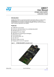
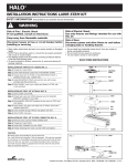
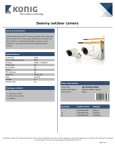
HALO L630 2C 2N POWER TRAC INSTALLATION INSTRUCTIONS
IMPORTANT SAFETY INSTRUCTIONS
When installing or using this track system, basic safety precautions
should always be followed, including the following:
8.
CAUTION: This track system is not intended for use with power supply cord or convenience receptacle adapter.
9
CAUTION: To reduce the risk of fire and electric shock, use only fixture assemblies marked for use with Halo track and track fittings
marked for use with L630 Series track.
1.
Read all of these instructions before installing the track system.
2.
Save these instructions and refer to them when additions to or
changes in the track configuration are made.
10. The track system is to be supplied by one or two 480V/277V 60Hz
single phase 3-wire system with a grounded neutral.
3.
Do not install this track in damp or wet locations.
4.
Do not install any part of a track system less than 5 feet above the
floor.
5.
Do not install any fixture assembly closer than 6 inches from any curtain or similar combustible material.
11. The mounting clips, screws or stems are to be mounted in pre-drilled
holes as follows:
4’ Track - two places - one at each end of track
8’ Track - Three places - one in the center and each end of the track
12’ Track - four places - one at each end of track and 4 feet from
each end
6.
Disconnect electrical power before adding to or changing the configuration of the track.
7.
Do not attempt to energize anything other than track lighting fixtures
on the track. To reduce the risk of fire and electric shock, do not
attempt to connect power tools, extension cords, appliances and the
like to the track.
If track requires field cutting, refer to field cutting instructions
12. CAUTION: The maximum capacity of L630 Track is 40A per circuit.
When installing, do not exceed the capacity of your circuits. Check
fuses and circuits carefully before installing.
SAVE THESE INSTRUCTIONS
INSTALLATION OF TRACK TO AN OUTLET BOX
Step 1.
Punch out proper knockout holes in ceiling plate for mounting to outlet box and to live end fitting (note that special smooth plastic finish
piece on metal ceiling plate requires caution in deterring location of
proper knockout before making holes). Remove flat head screw)s)
from back of live end fitting and use to fasten plate to fitting.
Step 2.
Remove cover from live end fitting. Place track with ceiling plate
attached over outlet box and mark on ceiling or wall the position of
the track mounting holes.
Step 3.
Drill mounting holes large enough for toggles and install track with furnished toggle bolts. If track is to be mounted on a solid surface, use
#8 screws (not supplied) instead of toggle bolts.
Step 4.
Fasten ceiling plate to outlet box with two screws. Pull wires from box
through open hole in live end as shown.
Step 5.
Cut and strip wires from box and fasten to screw terminals in live end
fitting (see detail). Push excess wire back into outlet box.
Step 6.
Replace cover on live end and tighten screw.
Figure 1
NEUTRAL
OUTLET
BOX
OUTLET
BOX
COVER
LIVE END
CONNECTOR
MOUNTING
SCREWS
LINE
COVER
SCREW
GREEN
GROUND
SCREW
NEUTRAL
LINE
TIGHTEN SCREW
AFTER INSERTING
IN TRACK
TRACK
Cooper Lighting • 1121 Highway 74 South • Peachtree City GA 30269 • 770-468-4800
703113
NEW CUT MUST BE
AT EXACT RIGHT
ANGLE (90°)
DEAD END FITTING
TO REMOVE, LOOSEN
SCREW AND SLIDE FITTING OUT
REDRILL MOUNTING
HOLE(S) IF NECESSARY
FIELD CUTTING TRACK TO SPECIAL LENGTHS
NOTE:
Cutting should be done preferably from the dead end of the
track.
Step 1.
Remove dead end fitting and pull copper bus bars and insulators flush or even with one end of the track.
Step 2.
With hacksaw, cut the flush end (the side with insulators and
bus bars even to end) to desired length. Be sure to allow 1/8”
for dead end fitting which must be reinstalled to the track end.
Step 3.
Remove all burrs from the track, insulators and copper bus
bars.
Step 4.
Push copper bus bars back into the insulators 3/8” from the
end of the insulators.
NOTE: After you complete Step 4, bus bar insulators should be
a minimum of 3/8” and a maximum of 1/2” from each end of the
insulator. If this is not the case, make appropriate modifications.
Step 5.
Reinstall the dead end and/or appropriate feed connector and
tighten the screw.
CAUTION: After track has been field cut, make certain that
each length of track that is 4 feet or less in length has one
mounting opening spaced a maximum of 6 inches from each
track end section. A single section of track that is greater than 4
feet in length must have mounting openings a maximum of 12
inches from each end of the track with additional openings a
minimum of every 4 feet long the length of the track section.
Additional openings may be provided as needed.
If additional mounting holes are required, follow this procedure:
Step 1. Locate desired mounting hole(s) on the inside of the
track section along the center line.
Step 2. Using 3/16” diameter drill bit, drill hole through the
track channel.
Caution: Take care that you do not damage the bus bar
insulators during the drilling operation. If you
accidentally damage any insulators, discard the track
section. DO NOT ATTEMPT TO USE IT IN THE
INSTALLATION.
Step 3. Remove all burrs and install track as described
above.
Additional Connectors Available
NOTE:
The T and X Connectors wiring patterns can be easily changed in the field by shifting jumping positions or eliminating wires. Several circuits
can be fed through any connector by removing two or more of the jumper wires and replacing them with feed wires. Separate instruction
sheets are packed with each connector.
L673
Straight connector for
straight runs.
L674
“L” connector for right
or left turns.
L675
“T” Connector for 3 leg
arrangements.
L676
X Connector for 4 leg
arrangements.
Cooper Lighting • 1121 Highway 74 South • Peachtree City GA 30269 • 770-468-4800
703113