1
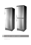
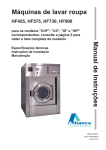
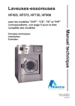
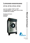
n.v.
IPSO - LSG
Instruction manual
HF455, HF575
Technical specifications
Installation instructions
Operating instructions
Maintenance
Nieuwstraat 146 - B-8560 Wevelgem (Belgium)
Tel. 056/41 20 54 - Fax 056/41 86 74
Part No. D0291
Contents
1 General safety instructions .............................................................
3
2 Technical data and dimensions .....................................................
4
Technical data ..............................................................................
4
Dimensions ..................................................................................
5
3 Installation and connection ............................................................
6
Ground .........................................................................................
6
Removing the transport brackets ...................................................
6
Water connection ..........................................................................
6
Water drain ...................................................................................
7
Main power connection ..................................................................
7
Automatic lubricator ......................................................................
8
Liquid soap connection .................................................................
9
Steam connection ......................................................................... 10
4 Operating instructions ................................................................... 11
5 Technical remarks ......................................................................... 13
Internal connection of the electrical heating ................................... 13
Tilt switch ..................................................................................... 13
6 Maintenance of the machine ......................................................... 14
Code: 249/00234/00
26/02/2003
Contents
1
General safety instructions
Ignoring any of the safety instructions can cause serious
personal injury and can also cause damage to the linen or the
machine
p
Read the installation and instruction manual carefully before connecting the
machine.
p
p
It is recommended that the machine be installed by qualified technicians.
p
The machine should be grounded according to the instructions in order to
eliminate the risk of electrocution.
p
p
Do not expose the machine to high humidity or extreme high or low temperatures.
p
p
Before starting repairs or maintenance, shut off all power and water supplies.
p
Always carefully read and follow the instructions on the packing of detergents.
Store these products out of the reach of children.
p
p
Always take into account the instructions on the labels of clothes.
The machine should be installed according to the installation instructions. (See
chapter 3)
Cut off all main water inlets, steam and electrical supplies at the end of each
operating day.
To prevent fire and explosion:
Keep the area around the machine free from inflammable or combustible
products.
Do not put fabrics that are treated with inflammable products into the machine.
These fabrics should be hand-washed or air-dried first.
Never allow children to play in the surroundings of a machine.
Remark:
p These instructions surely cannot prevent all risks of accidents. It is up to the user to act with the
utmost precaution.
p Do not hesitate to contact the dealer in case of a problem.
3
2
Technical data and dimensions
Technical data
HF 455
HF 575
40,9 kg
45 kg
50 kg
51,8 kg
57 kg
63,3 kg
980 mm
597 mm
450 Lit.
980 mm
775 mm
570 Lit.
1950 mm
1200 mm
1190 mm
1950 mm
1200 mm
1405 mm
Capacity (dry weight)
1/11
1/10
1/9
Cylinder
Diameter
Depth
Volume
Cabinet
Height
Width
Depth
Front loading
Diameter door opening
Door height - lower edge
Door height - center
395 mm
800 mm
1000 mm
Speed
Wash
Distribution
Spin
High spin
10--50 tr/min.
100 tr/min.
250--400 tr/min.
500--800 tr/min.
G-force
Spin
High spin
87
350
Motors (3-phase)
4p. 1470 rpm
7500W
Drain
Depend-O-Drain
3
Water-inlet
3/4"
Hard, soft, hot water
Steam connection
1/2"
Steam connection
Heating
27 kW
36 kW
X
X
X
Electric 220/380 V
Electric 380 V
Steam
Boiler fed
Boiler fed (with auxiliary heating)
Packing dimensions
(H x W x D)
With liquid soap pumps
Weight
Net
Gross
2100x1350x1430
2100x1550x1430
2100x1350x1630
2100x1350x1630
1000 kg
1200 kg
1100 kg
1300 kg
4
2
Afmetingen 455
p
p
p
p
p
p
p
p
p
p
A. Soft water connection 3/4"
B. Warm water connection 3/4"
C. Hard water connection 3/4"
D. Electrical connection
E. Electrical connection soap pumps
F. Main switch
G. Ventilation tub
H. Connection of the liquid soap hoses
I. Steam connection 1/2"
J. Water drain
5
2
Dimensions
p
p
p
p
p
p
p
p
p
p
A. Soft water connection 3/4"
B. Warm water connection 3/4"
C. Hard water connection 3/4"
D. Electrical connection
E. Electrical connection soap pumps
F. Main switch
G. Ventilation tub
H. Connection of the liquid soap hoses
I. Steam connection 1/2"
J. Water drain
6
3
Installation and connection
Ground
The machine must be placed on a flat, solid surface (metal base, concrete or solid
ground). It is recommended that the machine be anchored (M16) on the provided
places (A) in the base, especially in case of a plinth
(see Dimensions 2).
The machine must be placed entirely level. For easy maintenance it is recommended to keep a minimal distance of 600 mm between the wall and the back of the
machine.
If several machines are placed next to each another, there should be a minimal
distance of 30 mm between each machine.
Removing the transport brackets
To prevent damage during transportation, the machine has been equipped with
four red transport brackets (D) to eliminate every possible movement of the tub.
After the machine has been placed level, take off the service- and the back panel
to remove these transport brackets.
Important
The machine must never be activated before removing these transport
brackets.
Water connection
The machine is delivered with hoses with 3/4" connections. These hoses fit the
water inlet valves of the machine and the main water inlet taps. To ensure the
optimal functioning of the water inlet valves, the water pressure on the inlet
should be between 0,5 and 10 kg/cm² (7 and 145 psi). If the pressure is too low,
the cycle time will increase considerably.
In case of boiler fed machines, a minimum of hot water of 90°C should be available:
For the HFP455: 350 l. HFP575: 445l.
7
3
Water drain
The machine is equipped with a drain valve with 3" outer diameter (80 mm).
This drain valve should be connected to the drain by means of the drain
elbow which is delivered with the machine.
p The diameter of the main drain should be adapted to the water flow and
the number of machines. It should be sufficient to handle at least 160L/
min. per machine.
p It is necessary to connect the main drain at least on one side to an open
air-brake to allow ventilation.
p When the main drain has not been sufficiently deodorized, every
machine should be installed seperately with a deodorizer.
Electrical Connection
pRemove the cover plate at the back of the machine (see dimensions).
pConnect the power cable to the connectors R,S,T (3 x 220V) or R,S,T and
N (3 x 380V + N) and the ground wire.
Machine without electrical heating
Power of the breaker plugs:
220V 3AC
20 A
380V 3AC + N
20 A
Machine with electrical heating
Power of the breaker plugs:
27 kW
36 kW
220V 3AC
80 A
----
380V 3AC + N
63 A
80 A
After having connected the machine, check the spin direction of the drum. The drum should spin in the
direction of the arrow indicated on the door glass (clockwise). If the drum spins in the wrong sense, it can
cause damage to the motor and can cause water to splash out through the soap dispenser.
In case of a wrong spin direction, switch the position of the connectors of the motor circuit from R to S
and vice versa.
8
3
Automatic lubricator
The bearing house of the machine is equipped with a lubricating device (A)
which automatically lubricates the bearing during one year. Upon delivery
of the machine, this lubricator has not been brought into use. To this effect,
please put on the matching screw (B) in the foreseen opening of the
lubricator.
Ignoringthisinstructionwillinevitablycausedamagetothebearings!
9
3
Liquid soap connection (option)
Connection of the liquid soap
hoses
A rubber connection has been placed over the air break opening at the back
of the machine. There are 5 holes in this rubber connection, through each
of which a liquid soap hose can be driven (S1...S5). Press the hoses until they
appear well inside the soap dispenser.
The central gap in the rubber connection remains and serves as air breaker.
S1...S5
Electrical connection of
the liquid soap pumps
On machines equipped with a liquid soap connection, connect the wires
directly on the print board next to the ground wire connection (option).
Connect as indicated on the wiring diagram.
The two connectors on the right give a tension of 220V ~ (max. 4A) which
canbeappliedtodrive220V ~ soappumps.Ifmorethan
4A is required, an
external tension will have to be used. 6 connections have been provided,
of which one (S6) can be used to drive a waterproofing pump (e.g. for rain
coats, etc.).
The 220V can be transformed to other values to drive other type soap
pumps.
Example: pumps 24V ~.
Also, pumps with different operating tension can be combined.
Example: 5 pumps 220V ~ and 1 pump 24V ~.
With an external tension 24V DC
10
3
Steam connection
Machines with steam heating must have a steam valve between the steam
installation and the machine.
With direct steam injection into the machine
1.
2.
3.
3.
5.
6.
7.
Steam pipe
steam cut-off valve 3/8"
Pipe coupling 3/8"
Steam filter 3/8"
Magnetic steam valve 3/8"
Curve MF 3/8"
Steam hose with appropriate pipe coupling 3/8"
Added parts for steam heating with heat exchanger
3.
9.
10.
11.
12.
Double pipe coupling 1/2"
Condensation accumulator with filter 1/2"
Conical coupling MM 1/2"
Single window 1/2"
One-way valve 1/2"
M = inner wire, F = outer wire
The manufacturer is not responsible for damage or accidents caused by not following the installation instructions!
11
4
Operating instructions
Open the door
Press "A" and open the door.
A
Fill the drum
The machines have 5 wash programs. Sort the linen according to the quality and
the allowed wash temperature. Remove all nails, coins, etc. that can damage the linen
or the machine during the wash cycle. Turn sleeves of overcoats, shirts and blouses
inside out. To increase the wash action and thus the quality of the wash, it is
recommended to mix large and small pieces.
If the machine is filled less than 80% of the capacity, this could prevent a good
operation and can even damage the machine.
Overloading the machine can be the cause of low wash quality.
Close the door
Select program
Add detergent
Press the button of the desired program: (1-5)
Take the necessary soap compartments out of the soap dispenser and fill them with
the required detergents in function of the chosen program. Then put them back into
the soap dispenser, leaning against the axle of the drop valves.
See instruction manual PS 40 : “6 : Operating mode”.
Remark :
Bleach may never be added through the soap compartments. Use the external pump
at the back side of the machine for this purpose.
The dosing is to be programmed through soap inlet 4 (soap 4). See instruction
manual PS 40 : “ 4 : Programming mode”.
Liquid detergents can also be added through the external soap pumps. These soap
pumps are available as an option. Some machines are not equipped with a soap
dispenser, so that detergents can only be added this way.
Machines equipped with soap pumps do not have the bleach pump at the back of
the machine, but have it included in the group of pumps. See instruction manual
PS 40 : “ 4 : Programming mode”.
For more detailed information on the operation : see instruction manual PS 40.
12
4
Opening the door in case
of an emergency
A
To open the door in case of emergency (malfunction, etc.), remove the lock
cover plate (A). Subsequently,
insert a screwdriver from the left-hand side behind the lock mechanism (B) and
push back the black handle (C) while opening the doorhandle.
Before opening the door, be sure there is no water left in the tub, and
that the drum has come to a complete stop.
B
C
C
13
5
Technical remarks
Internal connections of the
electrical heating
Heating
s
3x220V
R5
3x380V
R5
27kW
3x3kW
3x3kW
3x3kW
s
s
s
LC1D1810
LC1D1810
LC1D1810
H
H
H
LC1D0901
LC1D0901
LC1D0901
36kW
3x4kW
3x4kW
3x4kW
----------------
----------------
s
s
s
LC1D1810
LC1D1810
LC1D1810
H
B = Black
Br = Brown
Gy = Grey
Tilt switch
1/2
1/2
Window
Bu = Blue
R = Red
W = White
The tilt switch is mounted on the solid part of the machine. There is a window around
the probe of the tilt switch that is mounted on the movable part of the machine.
When the machine goes out of balance by overloading or uneven distribution of
the linen, the tilt switch will interrupt this action to prevent damage to the machine.
1/3
Important
Probe
To guarantee good functioning, the probe should be centered horizontally
and vertically at 1/3 from the bottom of the tilt window (when machine drum
is empty).
14
6
Maintenance of the machine
General maintenance
Periodical maintenance
Repair and after-sales
service
p
Clean the entire cabinet of the machine regularly and remove all traces of soap,
etc....
p
p
p
Remove all detergent residue in the soap dispenser with hot water.
Clean the door gasket and remove all detergents and other products.
Shut off the main water, steam and power connections at the end of each day.
Do not change the setting of the water inlet taps on boiler fed machines once
these have been installed.
p
It is recommended to leave the door and the soap dispenser open after use, to
ventilate the machine.
p
The V-belts of the motors should be retightened after two to three months when
first used. This is necessary because these belts are subject to a one-time
stretching when first used. By ignoring this instruction, the belt starts to slip
after a few months and will brake shortly afterwards.
p
p
Check regularly if the filters of the water inlet are not blocked by calcification.
If a machine frequently skips the final spin, check whether the probe of the out
of balance switch is still in the appropriate position, that is horizontally
centered and vertically 1/3 from the bottom inside the window. (When the drum
is empty).
p
An obstructed drain can cause frequent interruption of spinning for safety
reasons.
p
The automatic lubricator needs to be replaced each year. (Order number: 212/
00002/00)
p
In case of important malfunctions and deficiencies which you cannot resolve
yourself, do not hesitate to contact the technical service of your distributor.
Data distributor: Name: ................................................................................
Address: .............................................................................
Tel.: ....................................................................................
Data machine: Type: ..................................................................................
Program: ............................................................................
Date of installation: .............................................................
Installed by: ........................................................................
Serial number: ....................................................................
Operation voltage and frequency: .........................................
The manufacturer reserves the right to change the content of this instruction manual, at all times and without previous notice.
15