1
CH A P T E R
7
Controlling Lightweight Access Points
This chapter describes the Cisco lightweight access points and explains how to connect them to the
controller and manage access point settings. It contains these sections:
•
Access Point Communication Protocols, page 7-2
•
Configuring Global Credentials for Access Points, page 7-5
•
Configuring Authentication for Access Points, page 7-9
•
Embedded Access Points, page 7-14
•
Autonomous Access Points Converted to Lightweight Mode, page 7-16
•
Cisco Workgroup Bridges, page 7-34
•
Configuring Backup Controllers, page 7-41
•
Configuring Failover Priority for Access Points, page 7-46
•
Configuring Country Codes, page 7-49
•
Migrating Access Points from the -J Regulatory Domain to the -U Regulatory Domain, page 7-55
•
Using the W56 Band in Japan, page 7-58
•
Dynamic Frequency Selection, page 7-58
•
Optimizing RFID Tracking on Access Points, page 7-59
•
Configuring Probe Request Forwarding, page 7-62
•
Retrieving the Unique Device Identifier on Controllers and Access Points, page 7-63
•
Performing a Link Test, page 7-64
•
Configuring Link Latency, page 7-67
•
Configuring Power over Ethernet, page 7-70
•
Configuring Flashing LEDs, page 7-74
•
Viewing Clients, page 7-74
Cisco Wireless LAN Controller Configuration Guide
OL-17037-01
7-1
Chapter 7
Controlling Lightweight Access Points
Access Point Communication Protocols
Access Point Communication Protocols
In controller software release 5.2 or later, Cisco lightweight access points use the IETF standard Control
and Provisioning of Wireless Access Points protocol (CAPWAP) to communicate between the controller
and other lightweight access points on the network. Controller software releases prior to 5.2 use the
Lightweight Access Point Protocol (LWAPP) for these communications.
CAPWAP, which is based on LWAPP, is a standard, interoperable protocol that enables a controller to
manage a collection of wireless access points. CAPWAP is being implemented in controller software
release 5.2 for these reasons:
•
To provide an upgrade path from Cisco products that use LWAPP to next-generation Cisco products
that use CAPWAP
•
To manage RFID readers and similar devices
•
To enable controllers to interoperate with third-party access points in the future
LWAPP-enabled access points can discover and join a CAPWAP controller, and conversion to a
CAPWAP controller is seamless. For example, the controller discovery process and the firmware
downloading process when using CAPWAP are the same as when using LWAPP. The one exception is
for Layer 2 deployments, which are not supported by CAPWAP.
You can deploy CAPWAP controllers and LWAPP controllers on the same network. The
CAPWAP-enabled software allows access points to join either a controller running CAPWAP or LWAPP.
The only exception is the Cisco Aironet 1140 Series Access Point, which supports only CAPWAP and
therefore joins only controllers running CAPWAP. For example, an 1130 series access point can join a
controller running either CAPWAP or LWAPP whereas an 1140 series access point can join only a
controller running CAPWAP.
Guidelines for Using CAPWAP
Follow these guidelines when using CAPWAP:
•
If your firewall is currently configured to allow traffic only from access points using LWAPP, you
must change the rules of the firewall to allow traffic from access points using CAPWAP.
•
Make sure that the CAPWAP UDP ports 5246 and 5247 (similar to the LWAPP UDP ports 12222
and 12223) are enabled and are not blocked by an intermediate device that could prevent an access
point from joining the controller.
•
If access control lists (ACLs) are in the control path between the controller and its access points,
you need to open new protocol ports to prevent access points from being stranded.
The Controller Discovery Process
In a CAPWAP environment, a lightweight access point discovers a controller by using CAPWAP
discovery mechanisms and then sends the controller a CAPWAP join request. The controller sends the
access point a CAPWAP join response allowing the access point to join the controller. When the access
point joins the controller, the controller manages its configuration, firmware, control transactions, and
data transactions.
Upgrade and downgrade paths from LWAPP to CAPWAP or from CAPWAP to LWAPP are supported.
An access point with an LWAPP image starts the discovery process in LWAPP. If it finds an LWAPP
controller, it starts the LWAPP discovery process to join the controller. If it does not find a LWAPP
controller, it starts the discovery in CAPWAP. If the number of times that the discovery process starts
Cisco Wireless LAN Controller Configuration Guide
7-2
OL-17037-01
Chapter 7
Controlling Lightweight Access Points
Access Point Communication Protocols
with one discovery type (CAPWAP or LWAPP) exceeds the maximum discovery count and the access
point does not receive a discovery response, the discovery type changes to the other type. For example,
if the access point does not discover the controller in LWAPP, it starts the discovery process in CAPWAP.
Note
If an access point is in the UP state and its IP address changes, the access point tears down the existing
CAPWAP tunnel and rejoins the controller. In previous software releases, the access point notifies the
controller, and the session continues with the changed IP address without tearing down the session.
Note
You must install software release 4.0.155.0 or later on the controller before connecting 1100 and 1300
series access points to the controller. The 1120 and 1310 access points were not supported prior to
software release 4.0.155.0.
Note
The Cisco controllers cannot edit or query any access point information using the CLI if the name of the
access point contains a space.
Note
Make sure that the controller is set to the current time. If the controller is set to a time that has already
occurred, the access point might not join the controller because its certificate may not be valid for that
time.
Access points must be discovered by a controller before they can become an active part of the network.
The lightweight access points support these controller discovery processes:
•
Layer 3 CAPWAP or LWAPP discovery—Can occur on different subnets from the access point
and uses IP addresses and UDP packets rather the MAC addresses used by Layer 2 discovery.
•
Over-the-air provisioning (OTAP)—This feature is supported by Cisco 4400 series controllers. If
this feature is enabled on the controller (on the controller General page), all associated access points
transmit wireless CAPWAP or LWAPP neighbor messages, and new access points receive the
controller IP address from these messages. This feature is disabled by default and should remain
disabled when all access points are installed.
Note
You can find additional information about OTAP at this link:
http://www.ciscosystems.com/en/US/products/ps6366/products_tech_note09186a008093d
74a.shtml
•
Locally stored controller IP address discovery—If the access point was previously associated to
a controller, the IP addresses of the primary, secondary, and tertiary controllers are stored in the
access point’s non-volatile memory. This process of storing controller IP addresses on an access
point for later deployment is called priming the access point.
•
DHCP server discovery—This feature uses DHCP option 43 to provide controller IP addresses to
the access points. Cisco switches support a DHCP server option that is typically used for this
capability. For more information about DHCP option 43, see the “Using DHCP Option 43 and
DHCP Option 60” section on page 7-24.
•
DNS discovery—The access point can discover controllers through your domain name server
(DNS). For the access point to do so, you must configure your DNS to return controller IP addresses
in response to CISCO-LWAPP-CONTROLLER.localdomain, where localdomain is the access point
Cisco Wireless LAN Controller Configuration Guide
OL-17037-01
7-3
Chapter 7
Controlling Lightweight Access Points
Access Point Communication Protocols
domain name. When an access point receives an IP address and DNS information from a DHCP
server, it contacts the DNS to resolve CISCO-LWAPP-CONTROLLER.localdomain. When the DNS
sends a list of controller IP addresses, the access point sends discovery requests to the controllers.
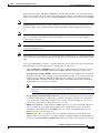
Verifying that Access Points Join the Controller
When replacing a controller, you need to make sure that access points join the new controller.
Using the GUI to Verify that Access Points Join the Controller
Follow these steps to ensure that access points join the new controller.
Step 1
Follow these steps to configure the new controller as a master controller.
a.
Click Controller > Advanced > Master Controller Mode to open the Master Controller
Configuration page.
b.
Check the Master Controller Mode check box.
c.
Click Apply to commit your changes.
d.
Click Save Configuration to save your changes.
Step 2
(Optional) Flush the ARP and MAC address tables within the network infrastructure. Ask your network
administrator for more information about this step.
Step 3
Restart the access points.
Step 4
Once all the access points have joined the new controller, configure the controller not to be a master
controller by unchecking the Master Controller Mode check box on the Master Controller
Configuration page.
Using the CLI to Verify that Access Points Join the Controller
Follow these steps to ensure that access points join the new controller.
Step 1
To configure the new controller as a master controller, enter this command:
config network master-base enable
Step 2
(Optional) Flush the ARP and MAC address tables within the network infrastructure. Ask your network
administrator for more information about this step.
Step 3
Restart the access points.
Step 4
To configure the controller not to be a master controller once all the access points have joined the new
controller, enter this command:
config network master-base disable
Cisco Wireless LAN Controller Configuration Guide
7-4
OL-17037-01
Chapter 7
Controlling Lightweight Access Points
Configuring Global Credentials for Access Points
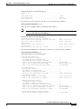
Viewing CAPWAP MTU Information
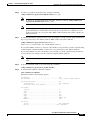
To view the maximum transmission unit (MTU) for the CAPWAP path on the controller, enter this
command. The MTU specifies the maximum size of any packet (in bytes) in a transmission.
show ap config general Cisco_AP
Information similar to the following appears:
Cisco AP Identifier.............................. 9
Cisco AP Name.................................... Maria-1250
Country code..................................... US - United States
Regulatory Domain allowed by Country............. 802.11bg:-A
802.11a:-A
AP Country code.................................. US - United States
AP Regulatory Domain............................. 802.11bg:-A
802.11a:-A
Switch Port Number .............................. 1
MAC Address...................................... 00:1f:ca:bd:bc:7c
IP Address Configuration......................... DHCP
IP Address....................................... 1.100.163.193
IP NetMask....................................... 255.255.255.0
CAPWAP Path MTU............................... 1485
...
Debugging CAPWAP
Use these CLI commands to obtain CAPWAP debug information:
•
debug capwap events {enable | disable}—Enables or disables debugging of CAPWAP events.
•
debug capwap errors {enable | disable}—Enables or disables debugging of CAPWAP errors.
•
debug capwap detail {enable | disable}—Enables or disables debugging of CAPWAP details.
•
debug capwap info {enable | disable}—Enables or disables debugging of CAPWAP information.
•
debug capwap packet {enable | disable}—Enables or disables debugging of CAPWAP packets.
•
debug capwap payload {enable | disable}—Enables or disables debugging of CAPWAP payloads.
•
debug capwap hexdump {enable | disable}—Enables or disables debugging of the CAPWAP
hexadecimal dump.
Configuring Global Credentials for Access Points
Cisco IOS access points are shipped from the factory with Cisco as the default enable password. This
password allows users to log into the non-privileged mode and execute show and debug commands,
posing a security threat. The default enable password must be changed to prevent unauthorized access
and to enable users to execute configuration commands from the access point’s console port.
In controller software releases prior to 5.0, you can set the access point enable password only for access
points that are currently connected to the controller. In controller software release 5.0 or later, you can
set a global username, password, and enable password that all access points inherit as they join the
controller. This includes all access points that are currently joined to the controller and any that join in
the future. If desired, you can override the global credentials and assign a unique username, password,
and enable password for a specific access point.
Cisco Wireless LAN Controller Configuration Guide
OL-17037-01
7-5
Chapter 7
Controlling Lightweight Access Points
Configuring Global Credentials for Access Points
Also in controller software release 5.0 or later, after an access point joins the controller, the access point
enables console port security, and you are prompted for your username and password whenever you log
into the access point’s console port. When you log in, you are in non-privileged mode, and you must
enter the enable password in order to use the privileged mode.
Note
These controller software release 5.0(or later) features are supported on all access points that have been
converted to lightweight mode, except the 1100 series. VxWorks access points are not supported.
The global credentials that you configure on the controller are retained across controller and access point
reboots. They are overwritten only if the access point joins a new controller that is configured with a
global username and password. If the new controller is not configured with global credentials, the access
point retains the global username and password configured for the first controller.
Note
You need to keep careful track of the credentials used by the access points. Otherwise, you might not be
able to log into an access point’s console port. If you ever need to return the access points to the default
Cisco/Cisco username and password, you must clear the controller’s configuration and the access point’s
configuration to return them to factory default settings. To clear the controller’s configuration, choose
Commands > Reset to Factory Default > Reset on the controller GUI, or enter clear config on the
controller CLI. To clear the access point’s configuration, enter clear ap config Cisco_AP on the
controller CLI. Once the access point rejoins a controller, it adopts the default Cisco/Cisco username and
password.
You can use the controller GUI or CLI to configure global credentials for access points that join the
controller.
Using the GUI to Configure Global Credentials for Access Points
Using the controller GUI, follow these steps to configure global credentials for access points that join
the controller.
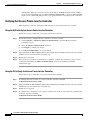
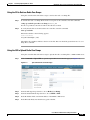
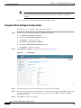
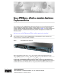
Step 1
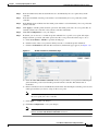
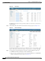
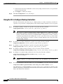
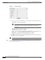
Click Wireless > Access Points > Global Configuration to open the Global Configuration page (see
Figure 7-1).
Figure 7-1
Global Configuration Page
Cisco Wireless LAN Controller Configuration Guide
7-6
OL-17037-01
Chapter 7
Controlling Lightweight Access Points
Configuring Global Credentials for Access Points
Step 2
In the Username field, enter the username that is to be inherited by all access points that join the
controller.
Step 3
In the Password field, enter the password that is to be inherited by all access points that join the
controller.
Step 4
In the Enable Password field, enter the enable password that is to be inherited by all access points that
join the controller.
Step 5
Click Apply to send the global username, password, and enable password to all access points that are
currently joined to the controller or that join the controller in the future.
Step 6
Click Save Configuration to save your changes.
Step 7
If desired, you can choose to override the global credentials for a specific access point and assign a
unique username, password, and enable password to this access point. Follow these steps to do so:
a.
Click Access Points > All APs to open the All APs page.
b.
Click the name of the access point for which you want to override the global credentials.
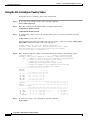
c.
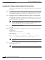
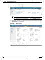
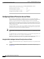
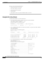
Click the Credentials tab. The All APs > Details for (Credentials) page appears (see Figure 7-2).
Figure 7-2
All APs > Details for (Credentials) Page
d.
Check the Over-ride Global Credentials check box to prevent this access point from inheriting the
global username, password, and enable password from the controller. The default value is
unchecked.
e.
In the Username, Password, and Enable Password fields, enter the unique username, password, and
enable password that you want to assign to this access point.
Note
The information that you enter is retained across controller and access point reboots and if
the access point joins a new controller.
f.
Click Apply to commit your changes.
g.
Click Save Configuration to save your changes.
Note
If you ever want to force this access point to use the controller’s global credentials, simply
uncheck the Over-ride Global Credentials check box.
Cisco Wireless LAN Controller Configuration Guide
OL-17037-01
7-7
Chapter 7
Controlling Lightweight Access Points
Configuring Global Credentials for Access Points
Using the CLI to Configure Global Credentials for Access Points
Using the controller CLI, follow these steps to configure global credentials for access points that join
the controller.
Step 1
To configure the global username, password, and enable password for all access points currently joined
to the controller as well as any access points that join the controller in the future, enter this command:
config ap mgmtuser add username user password password enablesecret enable_password all
Step 2
If desired, you can choose to override the global credentials for a specific access point and assign a
unique username, password, and enable password to this access point. To do so, enter this command:
config ap mgmtuser add username user password password enablesecret enable_password Cisco_AP
The credentials that you enter in this command are retained across controller and access point reboots
and if the access point joins a new controller.
Note
Step 3
If you ever want to force this access point to use the controller’s global credentials, enter this
command: config ap mgmtuser delete Cisco_AP. The following message appears after you
execute this command: “AP reverted to global username configuration.”
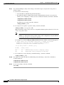
To save your changes, enter this command:
save config
Step 4
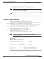
To verify that global credentials are configured for all access points that join the controller, enter this
command:
show ap summary
Information similar to the following appears:
Number of APs.................................... 1
Global AP User Name.............................. globalap
AP Name Slots AP Model
Ethernet MAC
Location
Port Country
-------- ------ ------------------- ------------------ ------------------ ---- ------HReap
2
AIR-AP1131AG-N-K9 00:13:80:60:48:3e default location 1
US
Note
Step 5
If global credentials are not configured, the Global AP User Name field shows “Not
Configured.”
To see the global credentials configuration for a specific access point, enter this command:
show ap config general Cisco_AP
Note
The name of the access point is case sensitive.
Cisco Wireless LAN Controller Configuration Guide
7-8
OL-17037-01
Chapter 7
Controlling Lightweight Access Points
Configuring Authentication for Access Points
Information similar to the following appears:
Cisco AP Identifier.............................. 0
Cisco AP Name.................................. HReap
...
AP User Mode..................................... AUTOMATIC
AP User Name..................................... globalap
...
Note
If this access point is configured for global credentials, the AP User Mode fields shows
“Automatic.” If the global credentials have been overwritten for this access point, the AP User
Mode field shows “Customized.”
Configuring Authentication for Access Points
You can configure 802.1X authentication between a lightweight access point and a Cisco switch. The
access point acts as an 802.1X supplicant and is authenticated by the switch using EAP-FAST with
anonymous PAC provisioning.
This feature is supported on the following hardware:
•
Cisco Aironet 1130, 1140, 1240, and 1250 series access points
•
All controller platforms running in local, hybrid-REAP, monitor, or sniffer mode. Bridge mode is
not supported.
Note
•
In hybrid-REAP mode, you cannot configure local switching with 802.1X authentication;
you can configure central switching only.
All Cisco switches that support authentication
Note
Refer to the Release Notes for Cisco Wireless LAN Controllers and Lightweight Access
Points for Release 5.2 for a list of supported switch hardware and minimum supported
software.
You can configure global authentication settings that all access points inherit as they join the controller.
This includes all access points that are currently joined to the controller and any that join in the future.
If desired, you can override the global authentication settings and assign unique authentication settings
for a specific access point.
Observe the following flow for configuring authentication for access points:
1.
If the access point is new, do the following:
a. Boot the access point with the installed recovery image.
b. If you choose not to follow this suggested flow and instead enable 802.1X authentication on the
switch port connected to the access point prior to the access point joining the controller, enter
the following command:
lwapp ap dot1x username username password password
Cisco Wireless LAN Controller Configuration Guide
OL-17037-01
7-9
Chapter 7
Controlling Lightweight Access Points
Configuring Authentication for Access Points
Note
If you choose to follow this suggested flow and enable 802.1X authentication on the
switch port after the access point has joined the controller and received the configured
802.1X credentials, you do not need to enter this command.
Note
This command is available only for access points that are running the 5.1 or 5.2 recovery
image.
c. Connect the access point to the switch port.
2.
Install the 5.1 or 5.2 image on the controller and reboot the controller.
3.
Allow all access points to join the controller.
4.
Configure authentication on the controller. See the “Using the GUI to Configure Authentication for
Access Points” section on page 7-10 or the “Using the CLI to Configure Authentication for Access
Points” section on page 7-12 for information on configuring authentication on the controller.
5.
Configure the switch to allow authentication. See the “Configuring the Switch for Authentication”
section on page 7-14 for information on configuring the switch for authentication.
Using the GUI to Configure Authentication for Access Points
Using the controller GUI, follow these steps to configure authentication for access points that join the
controller.
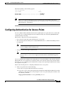
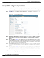
Step 1
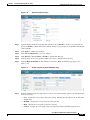
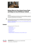
Click Wireless > Access Points > Global Configuration to open the Global Configuration page
(see Figure 7-3).
Figure 7-3
Global Configuration Page
Step 2
Under 802.1x Supplicant Credentials, check the 802.1x Authentication check box.
Step 3
In the Username field, enter the username that is to be inherited by all access points that join the
controller.
Cisco Wireless LAN Controller Configuration Guide
7-10
OL-17037-01
Chapter 7
Controlling Lightweight Access Points
Configuring Authentication for Access Points
Step 4
In the Password and Confirm Password fields, enter the password that is to be inherited by all access
points that join the controller.
Note
You must enter a strong password in these fields. Strong passwords have the following
characteristics:
- They are at least eight characters long.
- They contain a combination of upper- and lowercase letters, numbers, and symbols.
- They are not a word in any language.
Step 5
Click Apply to send the global authentication username and password to all access points that are
currently joined to the controller and to any that join the controller in the future.
Step 6
Click Save Configuration to save your changes.
Step 7
If desired, you can choose to override the global authentication settings and assign a unique username
and password to a specific access point. Follow these steps to do so:
a.
Click Access Points > All APs to open the All APs page.
b.
Click the name of the access point for which you want to override the authentication settings.
c.
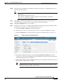
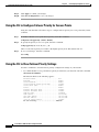
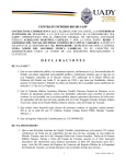
Click the Credentials tab to open the All APs > Details for (Credentials) page (see Figure 7-4).
Figure 7-4
All APs > Details for (Credentials) Page
d.
Under 802.1x Supplicant Credentials, check the Over-ride Global Credentials check box to
prevent this access point from inheriting the global authentication username and password from the
controller. The default value is unchecked.
e.
In the Username, Password, and Confirm Password fields, enter the unique username and password
that you want to assign to this access point.
Note
The information that you enter is retained across controller and access point reboots and
whenever the access point joins a new controller.
Cisco Wireless LAN Controller Configuration Guide
OL-17037-01
7-11
Chapter 7
Controlling Lightweight Access Points
Configuring Authentication for Access Points
f.
Click Apply to commit your changes.
g.
Click Save Configuration to save your changes.
Note
If you ever want to force this access point to use the controller’s global authentication
settings, simply uncheck the Over-ride Global Credentials check box.
Using the CLI to Configure Authentication for Access Points
Using the controller CLI, follow these steps to configure authentication for access points that join the
controller.
Step 1
To configure the global authentication username and password for all access points currently joined to
the controller as well as any access points that join the controller in the future, enter this command:
config ap dot1xuser add username user password password all
Note
Step 2
You must enter a strong password for the password parameter. Strong passwords have the
following characteristics:
- They are at least eight characters long.
- They contain a combination of upper- and lowercase letters, numbers, and symbols.
- They are not a word in any language.
If desired, you can choose to override the global authentication settings and assign a unique username
and password to a specific access point. To do so, enter this command:
config ap dot1xuser add username user password password Cisco_AP
Note
You must enter a strong password for the password parameter. See the note in Step 1 for the
characteristics of strong passwords.
The authentication settings that you enter in this command are retained across controller and access point
reboots and whenever the access point joins a new controller.
Note
Step 3
If you ever want to force this access point to use the controller’s global authentication settings,
enter this command: config ap dot1xuser delete Cisco_AP. The following message appears
after you execute this command: “AP reverted to global username configuration.”
To save your changes, enter this command:
save config
Cisco Wireless LAN Controller Configuration Guide
7-12
OL-17037-01
Chapter 7
Controlling Lightweight Access Points
Configuring Authentication for Access Points
Step 4
If you ever want to disable 802.1X authentication for all access points or for a specific access point, enter
this command:
config ap dot1xuser disable {all | Cisco_AP}
Note
Step 5
You can disable 802.1X authentication for a specific access point only if global 802.1X
authentication is not enabled. If global 802.1X authentication is enabled, you can disable 802.1X
for all access points only.
To view the authentication settings for all access points that join the controller, enter this command:
show ap summary
Information similar to the following appears:
Number of APs.................................... 1
Global AP User Name.............................. globalap
Global AP Dot1x User Name........................ globalDot1x
...
Note
Step 6
If global authentication settings are not configured, the Global AP Dot1x User Name field shows
“Not Configured.”
To view the authentication settings for a specific access point, enter this command:
show ap config general Cisco_AP
Note
The name of the access point is case sensitive.
Information similar to the following appears:
Cisco AP Identifier.............................. 0
Cisco AP Name.................................. HReap
...
AP Dot1x User Mode............................... AUTOMATIC
AP Dot1x User Name............................... globalDot1x
...
Note
If this access point is configured for global authentication, the AP Dot1x User Mode fields shows
“Automatic.” If the global authentication settings have been overwritten for this access point, the
AP Dot1x User Mode field shows “Customized.”
Cisco Wireless LAN Controller Configuration Guide
OL-17037-01
7-13
Chapter 7
Controlling Lightweight Access Points
Embedded Access Points
Configuring the Switch for Authentication
On the switch CLI, enter these commands to enable 802.1X authentication on a switch port:
Switch# configure terminal
Switch(config)# dot1x system-auth-control
Switch(config)# aaa new-model
Switch(config)# aaa authentication dot1x default group radius
Switch(config)# radius-server host ip_addr auth-port port acct-port port key key
Switch(config)# interface fastethernet2/1
Switch(config-if)# switchport mode access
Switch(config-if)# dot1x pae authenticator
Switch(config-if)# dot1x port-control auto
Switch(config-if)# end
Embedded Access Points
Controller software release 5.1 or later supports the AP801, which is the integrated access point on the
Cisco 800 Series Integrated Services Routers (ISRs). This access point uses a Cisco IOS software image
that is separate from the router Cisco IOS software image. It can operate as an autonomous access point
that is configured and managed locally, or it can operate as a centrally managed access point utilizing
the CAPWAP or LWAPP protocol. The AP801 is preloaded with both an autonomous Cisco IOS release
and a recovery image for the unified mode.
Note
Before you use an AP801 Series Lightweight Access Point with controller software release 5.2, you must
upgrade the software in the Cisco 800 Series Integrated Services Router (ISR) to Cisco IOS Release
12.4(22)T.
When you want to use the AP801 with a controller, you must enable the recovery image for the unified
mode on the access point by entering this CLI command on the router in privileged EXEC mode:
service-module wlan-ap 0 bootimage unified.
Note
If the service-module wlan-ap 0 bootimage unified command does not work successfully, make sure
that the software license is still eligible.
After enabling the recovery image, enter this CLI command on the router to shut down and reboot the
access point: service-module wlan-ap 0 reload. After the access point reboots, it discovers the
controller, downloads the full CAPWAP or LWAPP software release from the controller, and acts as a
lightweight access point.
Cisco Wireless LAN Controller Configuration Guide
7-14
OL-17037-01
Chapter 7
Controlling Lightweight Access Points
Embedded Access Points
Note
To use the CLI commands mentioned above, the router must be running Cisco IOS Release 12.4(20)T or
later. If you experience any problems, refer to the “Troubleshooting an Upgrade or Reverting the AP to
Autonomous Mode” section in the ISR configuration guide at this URL:
http://cisco.com/en/US/docs/routers/access/800/860-880-890/software/configuration/guide/admin_ap.h
tml#wp1061143
In order to support CAPWAP or LWAPP, the router must be activated with at least the Cisco Advanced
IP Services IOS license-grade image. A license is required to upgrade to this IOS image on the router.
Refer to this URL for licensing information:
http://cisco.com/en/US/docs/routers/access/800/860-880-890/software/activation/Software_Activation
_on_Cisco_Integrated_Routers.html
After the AP801 boots up with the recovery image for the unified mode, it requires an IP address to
communicate with the controller and to download its unified image and configuration from the
controller. The router can provide DHCP server functionality, the DHCP pool to reach the controller, and
setup option 43 for the controller IP address in the DHCP pool configuration. Use the following
configuration to perform this task:
ip dhcp pool pool_name
network ip_address subnet_mask
dns-server ip_address
default-router ip_address
option 43 hex controller_ip_address_in_hex
Example:
ip dhcp pool embedded-ap-pool
network 60.0.0.0 255.255.255.0
dns-server 171.70.168.183
default-router 60.0.0.1
option 43 hex f104.0a0a.0a0f
/* single WLC IP address(10.10.10.15) in hex format
*/
The AP801 802.11n radio supports lower power levels than the 802.11n radio in the Cisco Aironet 1250
series access points. The AP801 stores the radio power levels and passes them to the controller when the
access point joins the controller. The controller uses the supplied values to limit the user’s configuration.
The AP801 can be used in hybrid-REAP mode. Refer to Chapter 13 for more information on hybrid
REAP.
Note
For more information on the AP801, refer to the documentation for the Cisco 800 Series ISRs at this
URL:
http://www.cisco.com/en/US/products/hw/routers/ps380/tsd_products_support_series_home.html
Cisco Wireless LAN Controller Configuration Guide
OL-17037-01
7-15
Chapter 7
Controlling Lightweight Access Points
Autonomous Access Points Converted to Lightweight Mode
Autonomous Access Points Converted to Lightweight Mode
You can use an upgrade conversion tool to convert autonomous Cisco Aironet 1100, 1130AG, 1200,
1240AG, and 1300 Series Access Points to lightweight mode. When you upgrade one of these access
points to lightweight mode, the access point communicates with a controller and receives a configuration
and software image from the controller.
Refer to the Upgrading Autonomous Cisco Aironet Access Points to Lightweight Mode document for
instructions on upgrading an autonomous access point to lightweight mode. You can find this document
at this URL:
http://www.cisco.com/en/US/products/hw/wireless/ps430/prod_technical_reference09186a00804fc3dc
.html
Guidelines for Using Access Points Converted to Lightweight Mode
Keep these guidelines in mind when you use autonomous access points that have been converted to
lightweight mode:
•
Converted access points support 2006, 4400, and WiSM controllers only. When you convert an
autonomous access point to lightweight mode, the access point can communicate with Cisco 2006
series controllers, 4400 series controllers, or the controllers on a Cisco WiSM only.
•
Access points converted to lightweight mode do not support Wireless Domain Services (WDS).
Converted access points communicate only with Cisco wireless LAN controllers and cannot
communicate with WDS devices. However, the controller provides functionality equivalent to WDS
when the access point associates to it.
•
In controller software release 4.2 or later, all Cisco lightweight access points support 16 BSSIDs per
radio and a total of 16 wireless LANs per access point. In previous releases, they supported only 8
BSSIDs per radio and a total of 8 wireless LANs per access point. When a converted access point
associates to a controller, only wireless LANs with IDs 1 through 16 are pushed to the access point.
•
Access points converted to lightweight mode must get an IP address and discover the controller
using DHCP, DNS, or IP subnet broadcast.
•
After you convert an access point to lightweight mode, the console port provides read-only access
to the unit.
•
The 1130AG and 1240AG access points support hybrid-REAP mode. See Chapter 13 for details.
•
The upgrade conversion tool adds the self-signed certificate (SSC) key-hash to only one of the
controllers on the Cisco WiSM. After the conversion has been completed, add the SSC key-hash to
the second controller on the Cisco WiSM by copying the SSC key-hash from the first controller to
the second controller. To copy the SSC key-hash, open the AP Policies page of the controller GUI
(Security > AAA > AP Policies) and copy the SSC key-hash from the SHA1 Key Hash column
under AP Authorization List (see Figure 7-6). Then, using the second controller’s GUI, open the
same page and paste the key-hash into the SHA1 Key Hash field under Add AP to Authorization
List. If you have more than one Cisco WiSM, use WCS to push the SSC key-hash to all the other
controllers.
Cisco Wireless LAN Controller Configuration Guide
7-16
OL-17037-01
Chapter 7
Controlling Lightweight Access Points
Autonomous Access Points Converted to Lightweight Mode
Reverting from Lightweight Mode to Autonomous Mode
After you use the upgrade tool to convert an autonomous access point to lightweight mode, you can
convert the access point from a lightweight unit back to an autonomous unit by loading a Cisco IOS
release that supports autonomous mode (Cisco IOS release 12.3(7)JA or earlier). If the access point is
associated to a controller, you can use the controller to load the Cisco IOS release. If the access point is
not associated to a controller, you can load the Cisco IOS release using TFTP. In either method, the
access point must be able to access a TFTP server that contains the Cisco IOS release to be loaded.
Using a Controller to Return to a Previous Release
Follow these steps to revert from lightweight mode to autonomous mode using a wireless LAN
controller:
Step 1
Log into the CLI on the controller to which the access point is associated.
Step 2
Enter this command:
config ap tftp-downgrade tftp-server-ip-address filename access-point-name
Step 3
Wait until the access point reboots and reconfigure the access point using the CLI or GUI.
Using the MODE Button and a TFTP Server to Return to a Previous Release
Follow these steps to revert from lightweight mode to autonomous mode by using the access point
MODE (reset) button to load a Cisco IOS release from a TFTP server:
Step 1
The PC on which your TFTP server software runs must be configured with a static IP address in the range
of 10.0.0.2 to 10.0.0.30.
Step 2
Make sure that the PC contains the access point image file (such as c1200-k9w7-tar.123-7.JA.tar for a
1200 series access point) in the TFTP server folder and that the TFTP server is activated.
Step 3
Rename the access point image file in the TFTP server folder to c1200-k9w7-tar.default for a 1200
series access point.
Step 4
Connect the PC to the access point using a Category 5 (CAT5) Ethernet cable.
Step 5
Disconnect power from the access point.
Step 6
Press and hold the MODE button while you reconnect power to the access point.
Note
Step 7
The MODE button on the access point must be enabled. Follow the steps in the “Disabling the
Reset Button on Access Points Converted to Lightweight Mode” section on page 7-33 to check
the status of the access point MODE button.
Hold the MODE button until the status LED turns red (approximately 20 to 30 seconds), and release the
MODE button.
Cisco Wireless LAN Controller Configuration Guide
OL-17037-01
7-17
Chapter 7
Controlling Lightweight Access Points
Autonomous Access Points Converted to Lightweight Mode
Step 8
Wait until the access point reboots as indicated by all LEDs turning green followed by the Status LED
blinking green.
Step 9
After the access point reboots, reconfigure the access point using the GUI or the CLI.
Authorizing Access Points
In controller software releases prior to 5.2, the controller may either use self-signed certificates (SSCs)
to authenticate access points or send the authorization information to a RADIUS server (if access points
have manufactured-installed certificates [MICs]). In controller software release 5.2, you can configure
the controller to use a local significant certificate (LSC).
Authorizing Access Points Using SSCs
The Control and Provisioning of Wireless Access Points protocol (CAPWAP) secures the control
communication between the access point and controller by means of a secure key distribution requiring
X.509 certificates on both the access point and controller. CAPWAP relies on a priori provisioning of
the X.509 certificates. Cisco Aironet access points shipped before July 18, 2005 do not have a MIC, so
these access points create an SSC when upgraded to operate in lightweight mode. Controllers are
programmed to accept local SSCs for authentication of specific access points and do not forward those
authentication requests to a RADIUS server. This behavior is acceptable and secure.
Authorizing Access Points Using MICs
You can configure controllers to use RADIUS servers to authorize access points using MICs. The
controller uses an access point’s MAC address as both the username and password when sending the
information to a RADIUS server. For example, if the MAC address of the access point is 000b85229a70,
both the username and password used by the controller to authorize the access point are 000b85229a70.
Note
The lack of a strong password by the use of the access point’s MAC address should not be an issue
because the controller uses MIC to authenticate the access point prior to authorizing the access point
through the RADIUS server. Using MIC provides strong authentication.
Note
If you use the MAC address as the username and password for access point authentication on a RADIUS
AAA server, do not use the same AAA server for client authentication.
Cisco Wireless LAN Controller Configuration Guide
7-18
OL-17037-01
Chapter 7
Controlling Lightweight Access Points
Autonomous Access Points Converted to Lightweight Mode
Authorizing Access Points Using LSCs
You can use an LSC if you want your own public key infrastructure (PKI) to provide better security, to
have control of your certificate authority (CA), and to define policies, restrictions, and usages on the
generated certificates.
The LSC CA certificate is installed on access points and controllers. You need to provision the device
certificate on the access point. The access point gets a signed X.509 certificate by sending a certRequest
to the controller. The controller acts as a CA proxy and receives the certRequest signed by the CA for
the access point.
Note
Access points that are configured for bridge mode are not supported.
Using the GUI to Configure LSC
Using the controller GUI, follow these steps to enable the use of LSC on the controller.
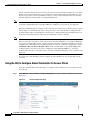
Step 1
Click Security > Certificate > LSC to open the Local Significant Certificates (LSC) page (see
Figure 7-5).
Figure 7-5
Local Significant Certificates (LSC) Page
Step 2
Click the General tab.
Step 3
To enable LSC on the system, check the Enable LSC on Controller check box.
Step 4
In the CA Server URL field, enter the URL to the CA server. You can enter either a domain name or an
IP address.
Step 5
In the Params fields, enter the parameters for the device certificate. The key size is a value from 384 to
2048 (in bits), and the default value is 2048.
Step 6
Click Apply to commit your changes.
Cisco Wireless LAN Controller Configuration Guide
OL-17037-01
7-19
Chapter 7
Controlling Lightweight Access Points
Autonomous Access Points Converted to Lightweight Mode
Step 7
To add the CA certificate into the controller’s CA certificate database, hover your cursor over the blue
drop-down arrow for the certificate type and choose Add.
Step 8
To provision the LSC on the access point, click the AP Provisioning tab and check the Enable AP
Provisioning check box.
Step 9
To add access points to the provision list, enter the access point MAC address in the AP Ethernet MAC
Addresses field and click Add.
Step 10
Note
To remove an access point from the provision list, hover your cursor over the blue drop-down
arrow for the access point and choose Remove.
Note
If you configure an access point provision list, only the access points in the provision list are
provisioned when you enable AP provisioning. If you do not configure an access point provision
list, all access points with a MIC or SSC certificate that join the controller are LSC provisioned.
Click Apply to commit your changes.
Using the CLI to Configure LSC
Using the controller CLI, follow these steps to enable the use of LSC on the controller.
Step 1
To enable LSC on the system, enter this command:
config certificate lsc {enable | disable}
Step 2
To configure the URL to the CA server, enter this command:
config certificate lsc ca-server http://url:port/path
where url can be either a domain name or IP address.
Note
Step 3
You can configure only one CA server. To configure a different CA server, delete the configured
CA server using the config certificate lsc ca-server delete command; then configure a different
CA server.
To add the LSC CA certificate into the controller’s CA certificate database, enter this command:
config certificate lsc ca-cert {add | delete}
Step 4
To configure the parameters for the device certificate, enter this command:
config certificate lsc subject-params country state city orgn dept email
Note
Step 5
The common name (CN) is generated automatically on the access point using the current
MIC/SSC format Cxxxx-MacAddr, where xxxx is the product number.
To configure a key size, enter this command:
config certificate lsc other-params keysize
The keysize is a value from 384 to 2048 (in bits), and the default value is 2048.
Cisco Wireless LAN Controller Configuration Guide
7-20
OL-17037-01
Chapter 7
Controlling Lightweight Access Points
Autonomous Access Points Converted to Lightweight Mode
Step 6
To add access points to the provision list, enter this command:
config certificate lsc ap-provision auth-list add AP_mac_addr
Step 7
Note
To remove access points from the provision list, enter this command: config certificate lsc
ap-provision auth-list delete AP_mac_addr.
Note
If you configure an access point provision list, only the access points in the provision list are
provisioned when you enable AP provisioning (in Step 8). If you do not configure an access
point provision list, all access points with a MIC or SSC certificate that join the controller are
LSC provisioned.
To configure the number of times that the access point attempts to join the controller using an LSC before
the access point reverts to the default certificate (MIC or SSC), enter this command:
config certificate lsc ap-provision revert-cert retries
where retries is a value from 0 to 255, and the default value is 3.
If you set the number of retries to a non-zero value and the access point fails to join the controller using
an LSC after the configured number of retries, the access point reverts to the default certificate.
If you set the number of retries to 0 and the access point fails to join the controller using an LSC, the
access point does not attempt to join the controller using the default certificate.
Note
Step 8
If you are configuring LSC for the first time, Cisco recommends that you configure a non-zero
value.
To provision the LSC on the access point, enter this command:
config certificate lsc ap-provision {enable | disable}
Step 9
To view the LSC summary, enter this command:
show certificate lsc summary
Information similar to the following appears:
LSC Enabled.......................................... Yes
LSC CA-Server........................................ http://10.0.0.1:8080/caserver
LSC AP-Provisioning.................................. Yes
Provision-List................................... Not Configured
LSC Revert Count in AP reboots................... 3
LSC Params:
Country..........................................
State............................................
City.............................................
Orgn.............................................
Dept.............................................
Email............................................
KeySize..........................................
4
ca
ss
org
dep
dep@co.com
390
LSC Certs:
CA Cert.......................................... Not Configured
RA Cert....................................... Not Configured
Cisco Wireless LAN Controller Configuration Guide
OL-17037-01
7-21
Chapter 7
Controlling Lightweight Access Points
Autonomous Access Points Converted to Lightweight Mode
Step 10
To view details about the access points that are provisioned using LSC, enter this command:
show certificate lsc ap-provision
Information similar to the following appears:
LSC AP-Provisioning........................... Yes
Provision-List................................ Present
Idx
--1
Mac Address
-----------00:18:74:c7:c0:90
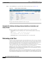
Using the GUI to Authorize Access Points
Using the controller GUI, follow these steps to authorize access points.
Step 1
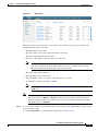
Click Security > AAA > AP Policies to open the AP Policies page (see Figure 7-6).
Figure 7-6
AP Policies Page
Step 2
If you want the access point to accept self-signed certificates (SSCs), manufactured-installed certificates
(MICs), or local significant certificates (LSCs), check the appropriate check box.
Step 3
If you want the access points to be authorized using a AAA RADIUS server, check the Authorize MIC
APs against auth-list or AAA check box.
Step 4
If you want the access points to be authorized using an LSC, check the Authorize LSC APs against
auth-list check box.
Step 5
Click Apply to commit your changes.
Step 6
Follow these steps to add an access point to the controller’s authorization list:
a.
Click Add to access the Add AP to Authorization List area.
b.
In the MAC Address field, enter the MAC address of the access point.
Cisco Wireless LAN Controller Configuration Guide
7-22
OL-17037-01
Chapter 7
Controlling Lightweight Access Points
Autonomous Access Points Converted to Lightweight Mode
c.
From the Certificate Type drop-down box, choose MIC, SSC, or LSC.
d.
Click Add. The access point appears in the access point authorization list.
Note
To remove an access point from the authorization list, hover your cursor over the blue drop-down
arrow for the access point and choose Remove.
Note
To search for a specific access point in the authorization list, enter the MAC address of the access
point in the Search by MAC field and click Search.
Using the CLI to Authorize Access Points
Using the controller CLI, follow these steps to authorize access points.
Step 1
To configure an access point authorization policy, enter this command:
config auth-list ap-policy {authorize-ap {enable | disable} | authorize-lsc-ap {enable | disable}}
Step 2
To configure an access point to accept manufactured-installed certificates (MICs), self-signed
certificates (SSCs), or local significant certificates (LSCs), enter this command:
config auth-list ap-policy {mic | ssc | lsc {enable | disable}}
Step 3
To add an access point to the authorization list, enter this command:
config auth-list add {mic | ssc | lsc} ap_mac [ap_key]
where ap_key is an optional key hash value equal to 20 bytes or 40 digits.
Note
Step 4
To delete an access point from the authorization list, enter this command:
config auth-list delete ap_mac.
To view the access point authorization list, enter this command:
show auth-list
Information similar to the following appears:
Authorize MIC APs against AAA ....................... disabled
Authorize LSC APs against Auth-List ................. disabled
Allow APs with MIC - Manufactured Installed C ....... enabled
Allow APs with SSC - Self-Signed Certificate ........ enabled
Allow APs with LSC - Locally Significant Cert ....... enabled
Mac Addr
----------------------00:12:79:de:65:99
00:16:36:91:9a:27
Cert Type
Key Hash
-----------------------------------------------------SSC
ca528236137130d37049a5ef3d1983b30ad7e543
MIC
593f34e7cb151997a28cc7da2a6cac040b329636
Cisco Wireless LAN Controller Configuration Guide
OL-17037-01
7-23
Chapter 7
Controlling Lightweight Access Points
Autonomous Access Points Converted to Lightweight Mode
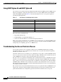
Using DHCP Option 43 and DHCP Option 60
Cisco Aironet access points use the type-length-value (TLV) format for DHCP option 43. DHCP servers
must be programmed to return the option based on the access point’s DHCP Vendor Class Identifier
(VCI) string (DHCP Option 60). Table 7-1 lists the VCI strings for Cisco access points capable of
operating in lightweight mode.
Table 7-1
VCI Strings For Lightweight Access Points
Access Point
VCI String
Cisco Aironet 1130 Series
Cisco AP c1130
Cisco Aironet 1140 Series
Cisco AP c1140
Cisco Aironet 1200 Series
Cisco AP c1200
Cisco Aironet 1240 Series
Cisco AP c1240
Cisco Aironet 1250 Series
Cisco AP c1250
Cisco AP801 Embedded Access Point
Cisco AP801
This is the format of the TLV block:
•
Type: 0xf1 (decimal 241)
•
Length: Number of controller IP addresses * 4
•
Value: List of the IP addresses of controller management interfaces
Refer to the product documentation for your DHCP server for instructions on configuring DHCP option
43. The Upgrading Autonomous Cisco Aironet Access Points to Lightweight Mode document contains
example steps for configuring option 43 on a DHCP server.
Troubleshooting the Access Point Join Process
Access points can fail to join a controller for many reasons: a RADIUS authorization is pending,
self-signed certificates are not enabled on the controller, the access point and controller’s regulatory
domains do not match, and so on.
Controller software release 5.2 enables you to configure the access points to send all CAPWAP-related
errors to a syslog server. You do not need to enable any debug commands on the controller because all
of the CAPWAP error messages can be viewed from the syslog server itself.
The state of the access point is not maintained on the controller until it receives a CAPWAP join request
from the access point. Therefore, it can be difficult to determine why the CAPWAP discovery request
from a certain access point was rejected. In order to troubleshoot such joining issues without enabling
CAPWAP debug commands on the controller, the controller collects information for all access points
that send a discovery message to this controller and maintains information for any access points that have
successfully joined this controller.
The controller collects all join-related information for each access point that sends a CAPWAP discovery
request to the controller. Collection begins with the first discovery message received from the access
point and ends with the last configuration payload sent from the controller to the access point.
Cisco Wireless LAN Controller Configuration Guide
7-24
OL-17037-01
Chapter 7
Controlling Lightweight Access Points
Autonomous Access Points Converted to Lightweight Mode
You can view join-related information for the following numbers of access points:
•
Up to 300 access points for 4400 series controllers, the Cisco WiSM, and the Catalyst 3750G
Integrated Wireless LAN Controller Switch
•
Up to three times the maximum number of access points supported by the platform for the 2100
series controllers and the Controller Network Module within the Cisco 28/37/38xx Series Integrated
Services Routers
When the controller is maintaining join-related information for the maximum number of access points,
it does not collect information for any more access points.
An access point sends all syslog messages to IP address 255.255.255.255 by default when any of the
following conditions are met:
•
An access point running software release 4.2 or later has been newly deployed.
•
An existing access point running a software release prior to 4.2 has been upgraded to 4.2 or a later
release.
•
An existing access point running software release 4.2 or later has been reset after clearing the
configuration.
If any of these conditions are met and the access point has not yet joined a controller, you can also
configure a DHCP server to return a syslog server IP address to the access point using option 7 on the
server. The access point then starts sending all syslog messages to this IP address.
You can also configure the syslog server IP address through the access point CLI, provided the access
point is currently not connected to the controller. The relevant command is lwapp ap log-server
syslog_server_IP_address.
When the access point joins a controller for the first time, the controller pushes the global syslog server
IP address (the default is 255.255.255.255) to the access point. After that, the access point sends all
syslog messages to this IP address, until it is overridden by one of the following scenarios:
•
The access point is still connected to the same controller, and the global syslog server IP address
configuration on the controller has been changed using the config ap syslog host global
syslog_server_IP_address command. In this case, the controller pushes the new global syslog server
IP address to the access point.
•
The access point is still connected to the same controller, and a specific syslog server IP address has
been configured for the access point on the controller using the config ap syslog host specific
Cisco_AP syslog_server_IP_address command. In this case, the controller pushes the new specific
syslog server IP address to the access point.
•
The access point gets disconnected from the controller, and the syslog server IP address has been
configured from the access point CLI using the lwapp ap log-server syslog_server_IP_address
command. This command works only if the access point is not connected to any controller.
•
The access point gets disconnected from the controller and joins another controller. In this case, the
new controller pushes its global syslog server IP address to the access point.
Whenever a new syslog server IP address overrides the existing syslog server IP address, the old address
is erased from persistent storage, and the new address is stored in its place. The access point also starts
sending all syslog messages to the new IP address, provided the access point can reach the syslog server
IP address.
You can configure the syslog server for access points and view the access point join information only
from the controller CLI.
Cisco Wireless LAN Controller Configuration Guide
OL-17037-01
7-25
Chapter 7
Controlling Lightweight Access Points
Autonomous Access Points Converted to Lightweight Mode
Configuring the Syslog Server for Access Points
Follow these steps to configure the syslog server for access points using the controller CLI.
Step 1
Perform one of the following:
•
To configure a global syslog server for all access points that join this controller, enter this command:
config ap syslog host global syslog_server_IP_address
Note
•
By default, the global syslog server IP address for all access points is 255.255.255.255.
Make sure that the access points can reach the subnet on which the syslog server resides
before configuring the syslog server on the controller. If the access points cannot reach this
subnet, the access points are unable to send out syslog messages.
To configure a syslog server for a specific access point, enter this command:
config ap syslog host specific Cisco_AP syslog_server_IP_address
Note
Step 2
By default, the syslog server IP address for each access point is 0.0.0.0, indicating that it is
not yet set. When the default value is used, the global access point syslog server IP address
is pushed to the access point.
To save your changes, enter this command:
save config
Step 3
To see the global syslog server settings for all access points that join the controller, enter this command:
show ap config global
Information similar to the following appears:
AP global system logging host.................... 255.255.255.255
Step 4
To see the syslog server settings for a specific access point, enter this command:
show ap config general Cisco_AP
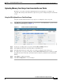
Viewing Access Point Join Information
Join statistics for an access point that sent a CAPWAP discovery request to the controller at least once
are maintained on the controller even if the access point is rebooted or disconnected. These statistics are
removed only if the controller is rebooted.
Use these CLI commands to view access point join information:
•
To see the MAC addresses of all the access points that are joined to the controller or that have tried
to join, enter this command:
show ap join stats summary all
Cisco Wireless LAN Controller Configuration Guide
7-26
OL-17037-01
Chapter 7
Controlling Lightweight Access Points
Autonomous Access Points Converted to Lightweight Mode
Information similar to the following appears:
Number of APs.............................................. 3
00:0b:85:1b:7c:b0.......................................... Joined
00:12:44:bb:25:d0.......................................... Joined
00:13:19:31:9c:e0.......................................... Not joined
•
To see the last join error detail for a specific access point, enter this command:
show ap join stats summary ap_mac
where ap_mac is the MAC address of the 802.11 radio interface.
Note
To obtain the MAC address of the 802.11 radio interface, enter this command on the access
point CLI: show interfaces Dot11Radio 0
Information similar to the following appears:
Is the AP currently connected to controller................
Time at which the AP joined this controller last time......
Type of error that occurred last...........................
disconnected
Reason for error that occurred last........................
the controller
Time at which the last join error occurred.................
•
Yes
Aug 21 12:50:36.061
AP got or has been
The AP has been reset by
Aug 21 12:50:34.374
To see all join-related statistics collected for a specific access point, enter this command:
show ap join stats detailed ap_mac
Information similar to the following appears:
Discovery phase statistics
- Discovery requests received..............................
- Successful discovery responses sent......................
- Unsuccessful discovery request processing................
- Reason for last unsuccessful discovery attempt...........
- Time at last successful discovery attempt................
- Time at last unsuccessful discovery attempt..............
Join phase statistics
- Join requests received...................................
- Successful join responses sent...........................
- Unsuccessful join request processing.....................
- Reason for last unsuccessful join attempt................
is pending for the AP
- Time at last successful join attempt.....................
- Time at last unsuccessful join attempt...................
Configuration phase statistics
- Configuration requests received..........................
- Successful configuration responses sent..................
- Unsuccessful configuration request processing............
- Reason for last unsuccessful configuration attempt.......
- Time at last successful configuration attempt............
- Time at last unsuccessful configuration attempt..........
2
2
0
Not applicable
Aug 21 12:50:23.335
Not applicable
1
1
1
RADIUS authorization
Aug 21 12:50:34.481
Aug 21 12:50:34.374
1
1
0
Not applicable
Aug 21 12:50:34.374
Not applicable
Last AP message decryption failure details
- Reason for last message decryption failure............... Not applicable
Cisco Wireless LAN Controller Configuration Guide
OL-17037-01
7-27
Chapter 7
Controlling Lightweight Access Points
Autonomous Access Points Converted to Lightweight Mode
Last AP disconnect details
- Reason for last AP connection failure.................... The AP has been reset by
the controller
Last join error summary
- Type of error that occurred last......................... AP got or has been
disconnected
- Reason for error that occurred last...................... The AP has been reset by
the controller
- Time at which the last join error occurred............... Aug 21 12:50:34.374
Using a Controller to Send Debug Commands to Access Points Converted to
Lightweight Mode
Enter this command to enable the controller to send debug commands to an access point converted to
lightweight mode:
debug ap {enable | disable | command cmd} Cisco_AP
When this feature is enabled, the controller sends debug commands to the converted access point as
character strings. You can send any debug command supported by Cisco Aironet access points that run
Cisco IOS software in lightweight mode.
Converted Access Points Send Crash Information to Controller
When a converted access point unexpectedly reboots, the access point stores a crash file on its local flash
memory at the time of the crash. After the unit reboots, it sends the reason for the reboot to the controller.
If the unit rebooted because of a crash, the controller pulls up the crash file using existing CAPWAP
messages and stores it in the controller flash memory. The crash info copy is removed from the access
point flash memory when the controller pulls it from the access point.
Converted Access Points Send Radio Core Dumps to Controller
When a radio module in a converted access point generates a core dump, the access point stores the core
dump file of the radio on its local flash memory at the time of the radio crash. It sends a notification
message to the controller indicating which radio generated a core dump file. The controller sends a trap
alerting the network administrator, and the administrator can retrieve the radio core file from the access
point.
The retrieved core file is stored in the controller flash and can subsequently be uploaded through TFTP
or FTP to an external server for analysis. The core file is removed from the access point flash memory
when the controller pulls it from the access point.
Cisco Wireless LAN Controller Configuration Guide
7-28
OL-17037-01
Chapter 7
Controlling Lightweight Access Points
Autonomous Access Points Converted to Lightweight Mode
Using the CLI to Retrieve Radio Core Dumps
Using the controller CLI, follow these steps to retrieve the radio core dump file.
Step 1
To transfer the radio core dump file from the access point to the controller, enter this command:
config ap crash-file get-radio-core-dump slot Cisco_AP
For the slot parameter, enter the slot ID of the radio that crashed.
Step 2
To verify that the file was downloaded to the controller, enter this command:
show ap crash-file
Information similar to the following appears:
Local Core Files:
lrad_AP1130.rdump0 (156)
The number in parentheses indicates the size of the file. The size should be greater than zero if a core
dump file is available.
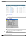
Using the GUI to Upload Radio Core Dumps
Using the controller GUI, follow these steps to upload the radio core dump file to a TFTP or FTP server.
Step 1
Click Commands > Upload File to open the Upload File from Controller page (see Figure 7-7).
Figure 7-7
Upload File from Controller Page
Step 2
From the File Type drop-down box, choose Radio Core Dump.
Step 3
From the Transfer Mode drop-down box, choose TFTP or FTP.
Step 4
In the IP Address field, enter the IP address of the TFTP or FTP server.
Step 5
In the File Path field, enter the directory path of the file.
Cisco Wireless LAN Controller Configuration Guide
OL-17037-01
7-29
Chapter 7
Controlling Lightweight Access Points
Autonomous Access Points Converted to Lightweight Mode
Step 6
In the File Name field, enter the name of the radio core dump file.
Note
Step 7
Step 8
The filename that you enter should match the filename generated on the controller. You can
determine the filename on the controller by entering the show ap crash-file command.
If you chose FTP as the Transfer Mode, follow these steps:
a.
In the Server Login Username field, enter the FTP server login name.
b.
In the Server Login Password field, enter the FTP server login password.
c.
In the Server Port Number field, enter the port number of the FTP server. The default value for the
server port is 21.
Click Upload to upload the radio core dump file from the controller. A message appears indicating the
status of the upload.
Using the CLI to Upload Radio Core Dumps
Using the controller CLI, follow these steps to upload the radio core dump file to a TFTP or FTP server.
Step 1
To transfer the file from the controller to a TFTP or FTP server, enter these commands:
•
transfer upload mode {tftp | ftp}
•
transfer upload datatype radio-core-dump
•
transfer upload serverip server_ip_address
•
transfer upload path server_path_to_file
•
transfer upload filename filename
Note
Step 2
If you are using an FTP server, also enter these commands:
•
transfer upload username username
•
transfer upload password password
•
transfer upload port port
Note
Step 3
The filename that you enter should match the filename generated on the controller. You can
determine the filename on the controller by entering the show ap crash-file command.
The default value for the port parameter is 21.
To view the updated settings, enter this command:
transfer upload start
Step 4
When prompted to confirm the current settings and start the software upload, answer y.
Cisco Wireless LAN Controller Configuration Guide
7-30
OL-17037-01
Chapter 7
Controlling Lightweight Access Points
Autonomous Access Points Converted to Lightweight Mode
Uploading Memory Core Dumps from Converted Access Points
By default, access points converted to lightweight mode do not send memory core dumps to the
controller. This section provides instructions to upload access point core dumps using the controller GUI
or CLI.
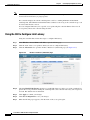
Using the GUI to Upload Access Point Core Dumps
Using the controller GUI, follow these steps to upload a core dump file of the access point.
Step 1
Click Wireless > Access Points > All APs > access point name > the Advanced tab to open the All APs
> Details for (Advanced) page (see Figure 7-8).
Figure 7-8
All APs > Details for (Advanced) Page
Step 2
To upload a core dump of the access point, check the AP Core Dump check box.
Step 3
In the TFTP Server IP field, enter the IP address of the TFTP server.
Step 4
In the File Name field, enter a name of the access point core dump file (such as dump.log).
Step 5
To compress the access point core dump file, check the File Compression check box. When you enable
this option, the file is saved with a .gz extension (such as dump.log.gz). This file can be opened with
WinZip.
Step 6
Click Apply to commit your changes.
Step 7
Click Save Configuration to save your changes.
Cisco Wireless LAN Controller Configuration Guide
OL-17037-01
7-31
Chapter 7
Controlling Lightweight Access Points
Autonomous Access Points Converted to Lightweight Mode
Using the CLI to Upload Access Point Core Dumps
Using the controller CLI, follow these steps to upload a core dump file of the access point.
Step 1
To upload a core dump of the access point, enter this command on the controller:
config ap core-dump enable tftp_server_ip_address filename {compress | uncompress} {ap_name |
all}
where
•
tftp_server_ip_address is the IP address of the TFTP server to which the access point sends core
dump files,
Note
•
filename is the name that the access points uses to label the core file,
•
compress configures the access point to send compressed core files whereas uncompress
configures the access point to send uncompressed core files, and
Note
•
Step 2
The access point must be able to reach the TFTP server.
When you choose compress, the file is saved with a .gz extension (for example,
dump.log.gz). This file can be opened with WinZip.
ap_name is the name of a specific access point for which core dumps are uploaded whereas all is all
access points converted to lightweight mode.
To save your changes, enter this command:
save config
Display of MAC Addresses for Converted Access Points
There are some differences in the way that controllers display the MAC addresses of converted access
points on information pages in the controller GUI:
•
On the AP Summary page, the controller lists the Ethernet MAC addresses of converted access
points.
•
On the AP Detail page, the controller lists the BSS MAC addresses and Ethernet MAC addresses of
converted access points.
•
On the Radio Summary page, the controller lists converted access points by radio MAC address.
Cisco Wireless LAN Controller Configuration Guide
7-32
OL-17037-01
Chapter 7
Controlling Lightweight Access Points
Autonomous Access Points Converted to Lightweight Mode
Disabling the Reset Button on Access Points Converted to Lightweight Mode
You can disable the reset button on access points converted to lightweight mode. The reset button is
labeled MODE on the outside of the access point.
Use this command to disable or enable the reset button on one or all converted access points associated
to a controller:
config ap reset-button {enable | disable} {ap-name | all}
The reset button on converted access points is enabled by default.
Configuring a Static IP Address on an Access Point Converted to Lightweight
Mode
After an access point converted to lightweight mode associates to a controller, enter this command to
configure a static IP address on the access point:
config ap static-ip enable ap-name ip-address mask gateway
Note
If you configure an access point to use a static IP address that is not on the same subnet on which the
access point’s previous DHCP address was, the access point falls back to a DHCP address after the
access point reboots. If the access point falls back to a DHCP address, the show ap config general
Cisco_AP CLI command correctly shows that the access point is using a fallback IP address. However,
the GUI shows both the static IP address and the DHCP address, but it does not identify the DHCP
address as a fallback address.
Supporting Oversized Access Point Images
Controller software release 5.0 or later allows you to upgrade to an oversized access point image by
automatically deleting the recovery image to create sufficient space. This feature affects only access
points with 8 MB of flash (the 1100, 1200, and 1310 series access points). All newer access points have
a larger flash size than 8 MB.
Note
As of August 2007, there are no oversized access point images, but as new features are added, the access
point image size will continue to grow.
The recovery image provides a backup image that can be used if an access point power-cycles during an
image upgrade. The best way to avoid the need for access point recovery is to prevent an access point
from power-cycling during a system upgrade. If a power-cycle occurs during an upgrade to an oversized
access point image, you can recover the access point using the TFTP recovery procedure.
Cisco Wireless LAN Controller Configuration Guide
OL-17037-01
7-33
Chapter 7
Controlling Lightweight Access Points
Cisco Workgroup Bridges
Follow these steps to perform the TFTP recovery procedure.
Step 1
Download the required recovery image from Cisco.com (c1100-rcvk9w8-mx, c1200-rcvk9w8-mx, or
c1310-rcvk9w8-mx) and install it in the root directory of your TFTP server.
Step 2
Connect the TFTP server to the same subnet as the target access point and power-cycle the access point.
The access point boots from the TFTP image and then joins the controller to download the oversized
access point image and complete the upgrade procedure.
Step 3
After the access point has been recovered, you may remove the TFTP server.
Cisco Workgroup Bridges
A workgroup bridge (WGB) is a mode that can be configured on an autonomous IOS access point to
provide wireless connectivity to a lightweight access point on behalf of clients that are connected by
Ethernet to the WGB access point. A WGB connects a wired network over a single wireless segment by
learning the MAC addresses of its wired clients on the Ethernet interface and reporting them to the
lightweight access point using Internet Access Point Protocol (IAPP) messaging. The WGB provides
wireless access connectivity to wired clients by establishing a single wireless connection to the
lightweight access point. The lightweight access point treats the WGB as a wireless client. See the
example in Figure 7-9.
Figure 7-9
WGB Example
Hub
Wired
clients
Switch
WGB
Access point
Controller
DHCP/ACS
/TFTB/FTP
Note
If the lightweight access point fails, the WGB attempts to associate to another access point.
Cisco Wireless LAN Controller Configuration Guide
7-34
OL-17037-01
Chapter 7
Controlling Lightweight Access Points
Cisco Workgroup Bridges
Guidelines for Using WGBs
Follow these guidelines for using WGBs on your network:
•
The WGB can be any autonomous access point that supports the workgroup bridge mode and is
running Cisco IOS Release 12.4(3g)JA or later (on 32-MB access points) or Cisco IOS Release
12.3(8)JEB or later (on 16-MB access points). These access points include the AP1120, AP1121,
AP1130, AP1231, AP1240, and AP1310. Cisco IOS Releases prior to 12.4(3g)JA and 12.3(8)JEB
are not supported.
Note
If your access point has two radios, you can configure only one for workgroup bridge mode.
This radio is used to connect to the lightweight access point. Cisco recommends that you
disable the second radio.
Note
The controller supports only Cisco WGB products. Linksys and OEM WGB devices are not
supported. Although the Cisco Wireless Unified Solution does not support the Linksys
WET54G and WET11B Ethernet Bridges, you can use these devices in a Wireless Unified
Solution configuration if you follow these guidelines:
1. Connect only one device to the WET54G or WET11B.
2. Enable the MAC cloning feature on the WET54G or WET11B to clone the connected
device.
3. Install the latest drivers and firmware on devices connected to the WET54G or WET11B.
This guideline is especially important for JetDirect printers because early firmware versions
might cause problems with DHCP.
Note: Because these devices are not supported in the Cisco Wireless Unified Solution, Cisco
Technical Support cannot help you troubleshoot any problems associated with them.
Perform one of the following to enable the workgroup bridge mode on the WGB:
– On the WGB access point GUI, choose Workgroup Bridge for the role in radio network on the
Settings > Network Interfaces page.
– On the WGB access point CLI, enter this command: station-role workgroup-bridge
Note
See the sample WGB access point configuration in the “Sample WGB Configuration”
section on page 7-37.
•
The WGB can associate only to lightweight access points.
•
Only WGBs in client mode (which is the default value) are supported. Those in infrastructure mode
are not supported. Perform one of the following to enable client mode on the WGB:
– On the WGB access point GUI, choose Disabled for the Reliable Multicast to WGB parameter.
– On the WGB access point CLI, enter this command: no infrastructure client.
Note
VLANs are not supported for use with WGBs.
Cisco Wireless LAN Controller Configuration Guide
OL-17037-01
7-35
Chapter 7
Controlling Lightweight Access Points
Cisco Workgroup Bridges
Note
•
See the sample WGB access point configuration in the “Sample WGB Configuration”
section on page 7-37.
These features are supported for use with a WGB:
– Guest N+1 redundancy
– Local EAP
– Open, WEP 40, WEP 128, CKIP, WPA+TKIP, WPA2+AES, LEAP, EAP-FAST, and EAP-TLS
authentication modes
•
These features are not supported for use with a WGB:
– Cisco Centralized Key Management (CCKM)
– Hybrid REAP
– Idle timeout
– Web authentication
Note
If a WGB associates to a web-authentication WLAN, the WGB is added to the exclusion
list, and all of the WGB wired clients are deleted.
•
The WGB supports a maximum of 20 wired clients. If you have more than 20 wired clients, use a
bridge or another device.
•
Wired clients connected to the WGB are not authenticated for security. Instead, the WGB is
authenticated against the access point to which it associates. Therefore, Cisco recommends that you
physically secure the wired side of the WGB.
•
With Layer 3 roaming, if you plug a wired client into the WGB network after the WGB has roamed
to another controller (for example, to a foreign controller), the wired client’s IP address displays
only on the anchor controller, not on the foreign controller.
•
If a wired client does not send traffic for an extended period of time, the WGB removes the client
from its bridge table, even if traffic is continuously being sent to the wired client. As a result, the
traffic flow to the wired client fails. To avoid the traffic loss, prevent the wired client from being
removed from the bridge table by configuring the aging-out timer on the WGB to a large value using
the following IOS commands on the WGB:
configure terminal
bridge bridge-group-number aging-time seconds
exit
end
where bridge-group-number is a value between 1 and 255, and seconds is a value between 10 and
1,000,000 seconds. Cisco recommends configuring the seconds parameter to a value greater than the
wired client’s idle period.
•
When you delete a WGB record from the controller, all of the WGB wired clients’ records are also
deleted.
•
Wired clients connected to a WGB inherit the WGB’s QoS and AAA override attributes.
Cisco Wireless LAN Controller Configuration Guide
7-36
OL-17037-01
Chapter 7
Controlling Lightweight Access Points
Cisco Workgroup Bridges
•
These features are not supported for wired clients connected to a WGB:
– MAC filtering
– Link tests
– Idle timeout
•
To enable the WGB to communicate with the lightweight access point, create a WLAN and make
sure that Aironet IE is enabled.
Sample WGB Configuration
Here is a sample configuration of a WGB access point using static WEP with a 40-bit WEP key:
ap#configure terminal
Enter configuration commands, one per line. End with CNTL/Z.
ap(config)#dot11 ssid WGB_with_static_WEP
ap(config-ssid)#authentication open
ap(config-ssid)#guest-mode
ap(config-ssid)#exit
ap(config)#interface dot11Radio 0
ap(config)#station-role workgroup-bridge
ap(config-if)#encry mode wep 40
ap(config-if)#encry key 1 size 40 0 1234567890
ap(config-if)#WGB_with_static_WEP
ap(config-if)#end
To verify that the WGB is associated to an access point, enter this command on the WGB:
show dot11 association
Information similar to the following appears:
ap#show dot11 associations
802.11 Client Stations on Dot11Radio0:
SSID [FCVTESTING] :
MAC Address
IP address
Device
000b.8581.6aee 10.11.12.1
WGB-client
ap#
Name
map1
Parent
-
State
Assoc
Using the GUI to View the Status of Workgroup Bridges
Follow these steps to view the status of WGBs on your network using the controller GUI.
Step 1
Click Monitor > Clients to open the Clients page (see Figure 7-10).
Cisco Wireless LAN Controller Configuration Guide
OL-17037-01
7-37
Chapter 7
Controlling Lightweight Access Points
Cisco Workgroup Bridges
Figure 7-10
Clients Page
The WGB field on the right side of the page indicates whether any of the clients on your network are
workgroup bridges.
Step 2
Click the MAC address of the desired client. The Clients > Detail page appears (see Figure 7-11).
Figure 7-11
Clients > Detail Page
The Client Type field under Client Properties shows “WGB” if this client is a workgroup bridge, and the
Number of Wired Client(s) field shows the number of wired clients that are connected to this WGB.
Step 3
To see the details of any wired clients that are connected to a particular WGB, follow these steps:
a.
Click Back on the Clients > Detail page to return to the Clients page.
b.
Hover your cursor over the blue drop-down arrow for the desired WGB and choose Show Wired
Clients. The WGB Wired Clients page appears (see Figure 7-12).
Cisco Wireless LAN Controller Configuration Guide
7-38
OL-17037-01
Chapter 7
Controlling Lightweight Access Points
Cisco Workgroup Bridges
Figure 7-12
Note
c.
WGB Wired Clients Page
If you ever want to disable or remove a particular client, hover your cursor over the blue
drop-down arrow for the desired client and choose Remove or Disable, respectively.
Click the MAC address of the desired client to see more details for this particular client. The Clients
> Detail page appears (see Figure 7-13).
Figure 7-13
Clients > Detail Page
The Client Type field under Client Properties shows “WGB Client,” and the rest of the fields on this
page provide additional information for this client.
Cisco Wireless LAN Controller Configuration Guide
OL-17037-01
7-39
Chapter 7
Controlling Lightweight Access Points
Cisco Workgroup Bridges
Using the CLI to View the Status of Workgroup Bridges
Follow these steps to view the status of WGBs on your network using the controller CLI.
Step 1
To see any WGBs on your network, enter this command:
show wgb summary
Information similar to the following appears:
Number of WGBs................................... 1
MAC Address
IP Address AP Name Status
----------------- ---------- -------- -----00:0d:ed:dd:25:82 10.24.8.73
a1
Assoc
Step 2
WLAN
---3
Auth Protocol Clients
----- --------- -------Yes
802.11b
1
To see the details of any wired clients that are connected to a particular WGB, enter this command:
show wgb detail wgb_mac_address
Information similar to the following appears:
Number of wired client(s): 1
MAC Address
IP Address AP Name Mobility
------------------- ---------- -------- --------00:0d:60:fc:d5:0b
10.24.8.75
a1
Local
WLAN
Auth
----- ----3
Yes
Using the CLI to Debug WGB Issues
Use the commands in this section if you experience any problems with the WGB.
1.
2.
To enable debugging for IAPP messages, errors, and packets, enter these commands:
•
debug iapp all enable—Enables debugging for IAPP messages.
•
debug iapp error enable—Enables debugging for IAPP error events.
•
debug iapp packet enable—Enables debugging for IAPP packets.
If you experience a roaming issue, enter this command:
debug mobility handoff enable
3.
4.
If you experience an IP assignment issue and DHCP is used, enter these commands:
•
debug dhcp message enable
•
debug dhcp packet enable
If you experience an IP assignment issue and static IP is used, enter these commands:
•
debug dot11 mobile enable
•
debug dot11 state enable
Cisco Wireless LAN Controller Configuration Guide
7-40
OL-17037-01
Chapter 7
Controlling Lightweight Access Points
Configuring Backup Controllers
Configuring Backup Controllers
A single controller at a centralized location can act as a backup for access points when they lose
connectivity with the primary controller in the local region. Centralized and regional controllers need
not be in the same mobility group. In controller software release 4.2 or later, you can specify a primary,
secondary, and tertiary controller for specific access points in your network. Using the controller GUI
or CLI, you can specify the IP addresses of the backup controllers, which allows the access points to fail
over to controllers outside of the mobility group.
In controller software release 5.0 or later, you can also configure primary and secondary backup
controllers (which are used if primary, secondary, or tertiary controllers are not specified or are not
responsive) for all access points connected to the controller as well as various timers, including heartbeat
timers and discovery request timers. To reduce the controller failure detection time, you can configure
the fast heartbeat interval (between the controller and the access point) with a smaller timeout value.
When the fast heartbeat timer expires (at every heartbeat interval), the access point determines if any
data packets have been received from the controller within the last interval. If no packets have been
received, the access point sends a fast echo request to the controller.
Note
You can configure the fast heartbeat timer only for access points in local and hybrid-REAP modes.
The access point maintains a list of backup controllers and periodically sends primary discovery requests
to each entry on the list. When the access point receives a new discovery response from a controller, the
backup controller list is updated. Any controller that fails to respond to two consecutive primary
discovery requests is removed from the list. If the access point’s local controller fails, it chooses an
available controller from the backup controller list in this order: primary, secondary, tertiary, primary
backup, secondary backup. The access point waits for a discovery response from the first available
controller in the backup list and joins the controller if it receives a response within the time configured
for the primary discovery request timer. If the time limit is reached, the access point assumes that the
controller cannot be joined and waits for a discovery response from the next available controller in the
list.
Note
When an access point’s primary controller comes back online, the access point disassociates from the
backup controller and reconnects to its primary controller. The access point falls back to its primary
controller and not to any secondary controller for which it is configured. For example, if an access point
is configured with primary, secondary, and tertiary controllers, it fails over to the tertiary controller when
the primary and secondary controllers become unresponsive and waits for the primary controller to come
back online so that it can fall back to the primary controller. The access point does not fall back from the
tertiary controller to the secondary controller if the secondary controller comes back online; it stays
connected to the tertiary controller until the primary controller comes back up.
Note
If you inadvertently configure a controller that is running software release 5.2 with a failover controller
that is running a different software release (such as 4.2, 5.0, or 5.1), the access point might take a long
time to join the failover controller because the access point starts the discovery process in CAPWAP and
then changes to LWAPP discovery.
Cisco Wireless LAN Controller Configuration Guide
OL-17037-01
7-41
Chapter 7
Controlling Lightweight Access Points
Configuring Backup Controllers
Using the GUI to Configure Backup Controllers
Using the controller GUI, follow these steps to configure primary, secondary, and tertiary controllers for
a specific access point and to configure primary and secondary backup controllers for all access points.
Step 1
Click Wireless > Access Points > Global Configuration to open the Global Configuration page (see
Figure 7-14).
Figure 7-14
Global Configuration Page
Step 2
From the Local Mode AP Fast Heartbeat Timer State drop-down box, choose Enable to enable the fast
heartbeat timer for access points in local mode or Disable to disable this timer. The default value is
Disable.
Step 3
If you chose Enable in Step 2, enter a number between 1 and 10 seconds (inclusive) in the Local Mode
AP Fast Heartbeat Timeout field to configure the fast heartbeat timer for access points in local mode.
Specifying a small heartbeat interval reduces the amount of time it takes to detect a controller failure.
The default value is 0 seconds, which disables the timer.
Step 4
From the H-REAP Mode AP Fast Heartbeat Timer State drop-down box, choose Enable to enable the
fast heartbeat timer for hybrid-REAP access points or Disable to disable this timer. The default value is
Disable.
Step 5
If you chose Enable in Step 4, enter a value between 1 and 10 seconds (inclusive) in the H-REAP Mode
AP Fast Heartbeat Timeout field to configure the fast heartbeat timer for hybrid-REAP access points.
Specifying a small heartbeat interval reduces the amount of time it takes to detect a controller failure.
The default value is 0 seconds, which disables the timer.
Step 6
In the AP Primary Discovery Timeout field, a value between 30 and 3600 seconds (inclusive) to
configure the access point primary discovery request timer. The default value is 120 seconds.
Cisco Wireless LAN Controller Configuration Guide
7-42
OL-17037-01
Chapter 7
Controlling Lightweight Access Points
Configuring Backup Controllers
Step 7
If you want to specify a primary backup controller for all access points, enter the IP address of the
primary backup controller in the Back-up Primary Controller IP Address field and the name of the
controller in the Back-up Primary Controller Name field.
Note
Step 8
The default value for the IP address is 0.0.0.0, which disables the primary backup controller.
If you want to specify a secondary backup controller for all access points, enter the IP address of the
secondary backup controller in the Back-up Secondary Controller IP Address field and the name of the
controller in the Back-up Secondary Controller Name field.
Note
The default value for the IP address is 0.0.0.0, which disables the secondary backup controller.
Step 9
Click Apply to commit your changes.
Step 10
If you want to configure primary, secondary, and tertiary backup controllers for a specific point, follow
these steps:
a.
Click Access Points > All APs to open the All APs page.
b.
Click the name of the access point for which you want to configure primary, secondary, and tertiary
backup controllers.
c.
Click the High Availability tab to open the All APs > Details for (High Availability) page (see
Figure 7-15).
Figure 7-15
d.
If desired, enter the name and IP address of the primary backup controller for this access point in
the Primary Controller fields.
Note
e.
All APs > Details for (High Availability) Page
Entering an IP address for the backup controller is optional in this step and the next two
steps. If the backup controller is outside the mobility group to which the access point is
connected (the primary controller), then you need to provide the IP address of the primary,
secondary, or tertiary controller, respectively. The controller name and IP address must
belong to the same primary, secondary, or tertiary controller. Otherwise, the access point
cannot join the backup controller.
If desired, enter the name and IP address of the secondary backup controller for this access point in
the Secondary Controller fields.
Cisco Wireless LAN Controller Configuration Guide
OL-17037-01
7-43
Chapter 7
Controlling Lightweight Access Points
Configuring Backup Controllers
Step 11
f.
If desired, enter the name and IP address of the tertiary backup controller for this access point in the
Tertiary Controller fields.
g.
Click Apply to commit your changes.
Click Save Configuration to save your changes.
Using the CLI to Configure Backup Controllers
Using the controller CLI, follow these steps to configure primary, secondary, and tertiary controllers for
a specific access point and to configure primary and secondary backup controllers for all access points.
Step 1
To configure a primary controller for a specific access point, enter this command:
config ap primary-base controller_name Cisco_AP [controller_ip_address]
Note
Step 2
The controller_ip_address parameter in this command and the next two commands is optional.
If the backup controller is outside the mobility group to which the access point is connected (the
primary controller), then you need to provide the IP address of the primary, secondary, or tertiary
controller, respectively. In each command, the controller_name and controller_ip_address must
belong to the same primary, secondary, or tertiary controller. Otherwise, the access point cannot
join the backup controller.
To configure a secondary controller for a specific access point, enter this command:
config ap secondary-base controller_name Cisco_AP [controller_ip_address]
Step 3
To configure a tertiary controller for a specific access point, enter this command:
config ap tertiary-base controller_name Cisco_AP [controller_ip_address]
Step 4
To configure a primary backup controller for all access points, enter this command:
config advanced backup-controller primary backup_controller_name backup_controller_ip_address
Step 5
To configure a secondary backup controller for all access points, enter this command:
config advanced backup-controller secondary backup_controller_name
backup_controller_ip_address
Note
Step 6
To delete a primary or secondary backup controller entry, enter 0.0.0.0 for the controller IP
address.
To enable or disable the fast heartbeat timer for local or hybrid-REAP access points, enter this command:
config advanced timers ap-fast-heartbeat {local | hreap | all} {enable | disable} interval
where all is both local and hybrid-REAP access points, and interval is a value between 1 and 10 seconds
(inclusive). Specifying a small heartbeat interval reduces the amount of time it takes to detect a controller
failure. The default value is disabled.
Cisco Wireless LAN Controller Configuration Guide
7-44
OL-17037-01
Chapter 7
Controlling Lightweight Access Points
Configuring Backup Controllers
Step 7
To configure the access point heartbeat timer, enter this command:
config advanced timers ap-heartbeat-timeout interval
where interval is a value between 1 and 30 seconds (inclusive). This value should be at least three times
larger than the fast heartbeat timer. The default value is 30 seconds.
Step 8
To configure the access point primary discovery request timer, enter this command:
config advanced timers ap-primary-discovery-timeout interval
where interval is a value between 30 and 3600 seconds. The default value is 120 seconds.
Step 9
To configure the access point discovery timer, enter this command:
config advanced timers ap-discovery-timeout interval
where interval is a value between 1 and 10 seconds (inclusive). The default value is 10 seconds.
Step 10
To configure the 802.11 authentication response timer, enter this command:
config advanced timers auth-timeout interval
where interval is a value between 10 and 600 seconds (inclusive). The default value is 10 seconds.
Step 11
To save your changes, enter this command:
save config
Step 12
To view an access point’s configuration, enter these commands:
•
show ap config general Cisco_AP
•
show advanced backup-controller
•
show advanced timers
Information similar to the following appears for the show ap config general Cisco_AP command:
Cisco AP Identifier..............................
Cisco AP Name....................................
Country code.....................................
Regulatory Domain allowed by Country.............
AP Country code..................................
AP Regulatory Domain.............................
Switch Port Number ..............................
MAC Address......................................
IP Address Configuration.........................
IP Address.......................................
...
Primary Cisco Switch Name........................
Primary Cisco Switch IP Address..................
Secondary Cisco Switch Name......................
Secondary Cisco Switch IP Address................
Tertiary Cisco Switch Name.......................
Tertiary Cisco Switch IP Address.................
...
1
AP5
US - United States
802.11bg:-AB
802.11a:-AB
US - United States
802.11bg:-A
802.11a:-N
1
00:13:80:60:48:3e
DHCP
1.100.163.133
1-4404
2.2.2.2
1-4404
2.2.2.2
2-4404
1.1.1.4
Information similar to the following appears for the show advanced backup-controller command:
AP primary Backup Controller .................... controller1 10.10.10.10
AP secondary Backup Controller ............... 0.0.0.0
Cisco Wireless LAN Controller Configuration Guide
OL-17037-01
7-45
Chapter 7
Controlling Lightweight Access Points
Configuring Failover Priority for Access Points
Information similar to the following appears for the show advanced timers command:
Authentication Response Timeout (seconds)........
Rogue Entry Timeout (seconds)....................
AP Heart Beat Timeout (seconds)..................
AP Discovery Timeout (seconds)...................
AP Local mode Fast Heartbeat (seconds)...........
AP Hreap mode Fast Heartbeat (seconds)...........
AP Primary Discovery Timeout (seconds)...........
10
1300
30
10
10 (enable)
disable
120
Configuring Failover Priority for Access Points
Each controller has a defined number of communication ports for access points. When multiple
controllers with unused access point ports are deployed on the same network and one controller fails, the
dropped access points automatically poll for unused controller ports and associate with them.
In controller software releases prior to 5.1, the backup controllers accept association requests in the
order the requests are received until all the ports are in use. As a result, the probability of an access point
finding an open port on a backup controller is determined by where in the association request queue it
is after the controller failure.
In controller software release 5.1 or later, you can configure your wireless network so that the backup
controller recognizes a join request from a higher-priority access point and if necessary disassociates a
lower-priority access point as a means to provide an available port.
Note
Failover priority is not in effect during the regular operation of your wireless network. It takes effect only
if there are more association requests after a controller failure than there are available backup controller
ports.
To configure this feature, you must enable failover priority on your network and assign priorities to the
individual access points. You can do so using the controller GUI or CLI.
By default, all access points are set to priority level 1, which is the lowest priority level. Therefore, you
need to assign a priority level only to those access points that warrant a higher priority.
Using the GUI to Configure Failover Priority for Access Points
Using the controller GUI, follow these steps to configure failover priority for access points that join the
controller.
Step 1
Click Wireless > Access Points > Global Configuration to open the Global Configuration page
(see Figure 7-16).
Cisco Wireless LAN Controller Configuration Guide
7-46
OL-17037-01
Chapter 7
Controlling Lightweight Access Points
Configuring Failover Priority for Access Points
Figure 7-16
Global Configuration Page
Step 2
From the Global AP Failover Priority drop-down box, choose Enable to enable access point failover
priority or Disable to disable this feature and turn off any access point priority assignments. The default
value is Disable.
Step 3
Click Apply to commit your changes.
Step 4
Click Save Configuration to save your changes.
Step 5
Click Wireless > Access Points > All APs to open the All APs page.
Step 6
Click the name of the access point for which you want to configure failover priority.
Step 7
Click the High Availability tab. The All APs > Details for (High Availability) page appears (see
Figure 7-17).
Figure 7-17
Step 8
All APs > Details for (High Availability) Page
From the AP Failover Priority drop-down box, choose one of the following options to specify the priority
of the access point:
•
Low—Assigns the access point to the level 1 priority, which is the lowest priority level. This is the
default value.
•
Medium—Assigns the access point to the level 2 priority.
•
High—Assigns the access point to the level 3 priority.
•
Critical—Assigns the access point to the level 4 priority, which is the highest priority level.
Cisco Wireless LAN Controller Configuration Guide
OL-17037-01
7-47
Chapter 7
Controlling Lightweight Access Points
Configuring Failover Priority for Access Points
Step 9
Click Apply to commit your changes.
Step 10
Click Save Configuration to save your changes.
Using the CLI to Configure Failover Priority for Access Points
Using the controller CLI, follow these steps to configure failover priority for access points that join the
controller.
Step 1
To enable or disable access point failover priority, enter this command:
config network ap-priority {enable | disable}
Step 2
To specify the priority of an access point, enter this command:
config ap priority {1 | 2 | 3 | 4} Cisco_AP
where 1 is the lowest priority level and 4 is the highest priority level. The default value is 1.
Step 3
To save your changes, enter this command:
save config
Using the CLI to View Failover Priority Settings
Use these commands to view the failover priority configuration settings on your network:
•
To confirm whether access point failover priority is enabled on your network, enter this command:
show network summary
Information similar to the following appears:
RF-Network Name............................. mrf
Web Mode.................................... Enable
Secure Web Mode............................. Enable
Secure Web Mode Cipher-Option High.......... Disable
Secure Shell (ssh).......................... Enable
Telnet...................................... Enable
Ethernet Multicast Mode..................... Disable
Ethernet Broadcast Mode..................... Disable
IGMP snooping............................... Disabled
IGMP timeout................................ 60 seconds
User Idle Timeout........................... 300 seconds
ARP Idle Timeout............................ 300 seconds
Cisco AP Default Master..................... Disable
AP Join Priority......................... Enabled
...
Cisco Wireless LAN Controller Configuration Guide
7-48
OL-17037-01
Chapter 7
Controlling Lightweight Access Points
Configuring Country Codes
•
To see the failover priority for each access point, enter this command:
show ap summary
Information similar to the following appears:
Number of APs.................................... 2
Global AP User Name.............................. user
Global AP Dot1x User Name........................ Not Configured
AP Name
------ap:1252
ap:1121
Slots
----2
1
AP Model
-----------------AIR-LAP1252AG-A-K9
AIR-LAP1121G-A-K9
Ethernet MAC
----------------00:1b:d5:13:39:74
00:1b:d5:a9:ad:08
Location
--------hallway 6
reception
Port
---1
1
Country
------US
US
Priority
------1
3
Configuring Country Codes
Controllers and access points are designed for use in many countries with varying regulatory
requirements. The radios within the access points are assigned to a specific regulatory domain at the
factory (such as -E for Europe), but the country code enables you to specify a particular country of
operation (such as FR for France or ES for Spain). Configuring a country code ensures that each radio’s
broadcast frequency bands, interfaces, channels, and transmit power levels are compliant with
country-specific regulations.
Generally, you configure one country code per controller, the one matching the physical location of the
controller and its access points. However, controller software release 4.1 or later allows you to configure
up to 20 country codes per controller. This multiple-country support enables you to manage access points
in various countries from a single controller.
Note
Although the controller supports different access points in different regulatory domains (countries), it
requires all radios in a single access point to be configured for the same regulatory domain. For example,
you should not configure a Cisco 1231 access point’s 802.11b/g radio for the US (-A) regulatory domain
and its 802.11a radio for the Great Britain (-E) regulatory domain. Otherwise, the controller allows only
one of the access point’s radios to turn on, depending on which regulatory domain you selected for the
access point on the controller. Therefore, make sure that the same country code is configured for both of
the access point’s radios.
For a complete list of country codes supported per product, refer to www.ciscofax.com or
http://www.cisco.com/en/US/prod/collateral/wireless/ps5679/ps5861/product_data_sheet0900aecd805
37b6a_ps6087_Products_Data_Sheet.html.
Guidelines for Configuring Multiple Country Codes
Follow these guidelines when configuring multiple country codes:
•
When the multiple-country feature is being used, all controllers intended to join the same RF group
must be configured with the same set of countries, configured in the same order.
•
When multiple countries are configured and the radio resource management (RRM) auto-RF feature
is enabled, the auto-RF feature is limited to only the channels that are legal in all configured
countries and to the lowest power level common to all configured countries. The access points are
always able to use all legal frequencies, but non-common channels can only be assigned manually.
Cisco Wireless LAN Controller Configuration Guide
OL-17037-01
7-49
Chapter 7
Controlling Lightweight Access Points
Configuring Country Codes
Note
If an access point was already set to a higher legal power level or is configured manually,
the power level is limited only by the particular country to which that access point is
assigned.
You can configure country codes through the controller GUI or CLI.
Using the GUI to Configure Country Codes
Follow these steps to configure country codes using the GUI.
Step 1
Step 2
Follow these steps to disable the 802.11a and 802.11b/g networks:
a.
Click Wireless > 802.11a/n > Network.
b.
Uncheck the 802.11a Network Status check box.
c.
Click Apply to commit your changes.
d.
Click Wireless > 802.11b/g/n > Network.
e.
Uncheck the 802.11b/g Network Status check box.
f.
Click Apply to commit your changes.
Click Wireless > Country to open the Country page (see Figure 7-18).
Figure 7-18
Country Page
Step 3
Check the check box for each country where your access points are installed.
Step 4
If you checked more than one check box in Step 3, a message appears indicating that RRM channels and
power levels are limited to common channels and power levels. Click OK to continue or Cancel to
cancel the operation.
Step 5
Click Apply to commit your changes.
Cisco Wireless LAN Controller Configuration Guide
7-50
OL-17037-01
Chapter 7
Controlling Lightweight Access Points
Configuring Country Codes
Step 6
If you selected multiple country codes in Step 3, each access point is assigned to a country. Follow these
steps to see the default country chosen for each access point and to choose a different country if
necessary.
Note
a.
If you ever remove a country code from the configuration, any access points currently assigned
to the deleted country reboot and when they rejoin the controller, they get re-assigned to one of
the remaining countries if possible.
Perform one of the following:
– Leave the 802.11a and 802.11b/g networks disabled.
– Re-enable the 802.11a and 802.11b/g networks and then disable only the access points for
which you are configuring a country code. To disable an access point, click Wireless > Access
Points > All APs, click the link of the desired access point, choose Disable from the Status
drop-down box, and click Apply.
b.
Click Wireless > Access Points > All APs to open the All APs page.
c.
Click the link for the desired access point.
d.
Click the Advanced tab to open the All APs > Details for (Advanced) page (see Figure 7-19).
Figure 7-19
All APs > Details for (Advanced) Page
e.
The default country for this access point appears in the Country Code drop-down box. If the access
point is installed in a country other than the one shown, choose the correct country from the
drop-down box. The box contains only those country codes that are compatible with the regulatory
domain of at least one of the access point’s radios.
f.
Click Apply to commit your changes.
g.
Repeat these steps to assign all access points joined to the controller to a specific country.
h.
Re-enable any access points that you disabled in Step a.
Step 7
Re-enable the 802.11a and 802.11b/g networks, provided you did not re-enable them in Step 6.
Step 8
Click Save Configuration to save your settings.
Cisco Wireless LAN Controller Configuration Guide
OL-17037-01
7-51
Chapter 7
Controlling Lightweight Access Points
Configuring Country Codes
Using the CLI to Configure Country Codes
Follow these steps to configure country codes using the CLI.
Step 1
To see a list of all available country codes, enter this command:
show country supported
Step 2
Enter these commands to disable the 802.11a and 802.11b/g networks:
config 802.11a disable network
config 802.11b disable network
Step 3
To configure the country codes for the countries where your access points are installed, enter this
command:
config country code1[,code2,code3,...]
If you are entering more than one country code, separate each by a comma (for example, config country
US,CA,MX). Information similar to the following appears:
Changing country code could reset channel configuration.
If running in RFM One-Time mode, reassign channels after this command.
Check customized APs for valid channel values after this command.
Are you sure you want to continue? (y/n) y
Step 4
Enter Y when prompted to confirm your decision. Information similar to the following appears:
Configured Country............................. Multiple Countries:US,CA,MX
Auto-RF for this country combination is limited to common channels and power.
KEY: * = Channel is legal in this country and may be configured manually.
A = Channel is the Auto-RF default in this country.
. = Channel is not legal in this country.
C = Channel has been configured for use by Auto-RF.
x = Channel is available to be configured for use by Auto-RF.
(-) = Regulatory Domains allowed by this country.
------------:+-+-+-+-+-+-+-+-+-+-+-+-+-+802.11BG
:
Channels
:
1 1 1 1 1
: 1 2 3 4 5 6 7 8 9 0 1 2 3 4
------------:+-+-+-+-+-+-+-+-+-+-+-+-+-+US (-AB)
: A * * * * A * * * * A . . .
CA (-AB)
: A * * * * A * * * * A . . .
MX (-NA)
: A * * * * A * * * * A . . .
Auto-RF
: C x x x x C x x x x C . . .
------------:+-+-+-+-+-+-+-+-+-+-+-+-+-+-+-+-+-+-+-+-+-+-+-+-+-+-+-+802.11A
:
1 1 1 1 1 1 1 1 1 1 1 1 1 1 1 1
Channels
: 3 3 3 4 4 4 4 4 5 5 6 6 0 0 0 1 1 2 2 2 3 3 4 4 5 5 6 6
--More-- or (q)uit
: 4 6 8 0 2 4 6 8 2 6 0 4 0 4 8 2 6 0 4 8 2 6 0 9 3 7 1 5
------------:+-+-+-+-+-+-+-+-+-+-+-+-+-+-+-+-+-+-+-+-+-+-+-+-+-+-+-+US (-AB)
: . A . A . A . A A A A A * * * * * . . . * * * A A A A *
CA (-ABN) : . A . A . A . A A A A A * * * * * . . . * * * A A A A *
MX (-N)
: . A . A . A . A A A A A . . . . . . . . . . . A A A A *
Auto-RF : . C . C . C . C C C C C . . . . . . . . . . . C C C C x
Step 5
To verify your country code configuration, enter this command:
show country
Cisco Wireless LAN Controller Configuration Guide
7-52
OL-17037-01
Chapter 7
Controlling Lightweight Access Points
Configuring Country Codes
Step 6
To see the list of available channels for the country codes configured on your controller, enter this
command:
show country channels
Information similar to the following appears:
Configured Country............................. Multiple Countries:US,CA,MX
Auto-RF for this country combination is limited to common channels and power.
KEY: * = Channel is legal in this country and may be configured manually.
A = Channel is the Auto-RF default in this country.
. = Channel is not legal in this country.
C = Channel has been configured for use by Auto-RF.
x = Channel is available to be configured for use by Auto-RF.
(-) = Regulatory Domains allowed by this country.
------------:+-+-+-+-+-+-+-+-+-+-+-+-+-+802.11BG
:
Channels
:
1 1 1 1 1
: 1 2 3 4 5 6 7 8 9 0 1 2 3 4
------------:+-+-+-+-+-+-+-+-+-+-+-+-+-+US (-AB)
: A * * * * A * * * * A . . .
CA (-AB)
: A * * * * A * * * * A . . .
MX (-NA)
: A * * * * A * * * * A . . .
Auto-RF
: C x x x x C x x x x C . . .
------------:+-+-+-+-+-+-+-+-+-+-+-+-+-+-+-+-+-+-+-+-+-+-+-+-+-+-+-+802.11A
:
1 1 1 1 1 1 1 1 1 1 1 1 1 1 1 1
Channels
: 3 3 3 4 4 4 4 4 5 5 6 6 0 0 0 1 1 2 2 2 3 3 4 4 5 5 6 6
: 4 6 8 0 2 4 6 8 2 6 0 4 0 4 8 2 6 0 4 8 2 6 0 9 3 7 1 5
------------:+-+-+-+-+-+-+-+-+-+-+-+-+-+-+-+-+-+-+-+-+-+-+-+-+-+-+-+US (-AB)
: . A . A . A . A A A A A * * * * * . . . * * * A A A A *
CA (-ABN) : . A . A . A . A A A A A * * * * * . . . * * * A A A A *
MX (-N)
: . A . A . A . A A A A A . . . . . . . . . . . A A A A *
Auto-RF : . C . C . C . C C C C C . . . . . . . . . . . C C C C x
------------:+-+-+-+-+-+-+-+-+-+-+-+-+-+-+-+-+-+-+-+-+-+-+-+-+-+-+-+-
Step 7
To save your settings, enter this command:
save config
Step 8
To see the countries to which your access points have been assigned, enter this command:
show ap summary
Information similar to the following appears:
Number of APs.................................... 2
AP Name Slots AP Model
-------- ------ ----------------ap1
2
AP1030
ap2
2
AIR-AP1242AG-A-K9
Ethernet MAC
----------------00:0b:85:5b:8e:c0
00:14:1c:ed:27:fe
Location
---------------default location
default location
Port
Country
------- -------1
US
1
US
Cisco Wireless LAN Controller Configuration Guide
OL-17037-01
7-53
Chapter 7
Controlling Lightweight Access Points
Configuring Country Codes
Step 9
If you entered multiple country codes in Step 3, follow these steps to assign each access point to a
specific country:
a.
Perform one of the following:
– Leave the 802.11a and 802.11b/g networks disabled.
– Re-enable the 802.11a and 802.11b/g networks and then disable only the access points for
which you are configuring a country code. To re-enable the networks, enter these commands:
config 802.11a enable network
config 802.11b enable network
To disable an access point, enter this command:
config ap disable ap_name
b.
To assign an access point to a specific country, enter this command:
config ap country code {ap_name | all}
Make sure that the country code you choose is compatible with the regulatory domain of at least one
of the access point’s radios.
Note
If you enabled the networks and disabled some access points and then run the config ap
country code all command, the specified country code is configured on only the disabled
access points. All other access points are ignored.
For example, if you enter config ap country mx all, information similar to the following appears:
To change country code: first disable target AP(s) (or disable all networks).
Changing the country may reset any customized channel assignments.
Changing the country will reboot disabled target AP(s).
Are you sure you want to continue? (y/n) y
AP Name
--------ap2
ap1
c.
Country
-------US
MX
Status
-------enabled (Disable AP before configuring country)
changed (New country configured, AP rebooting)
To re-enable any access points that you disabled in Step a, enter this command:
config ap enable ap_name
Step 10
If you did not re-enable the 802.11a and 802.11b/g networks in Step 9, enter these commands to
re-enable them now:
config 802.11a enable network
config 802.11b enable network
Step 11
To save your settings, enter this command:
save config
Cisco Wireless LAN Controller Configuration Guide
7-54
OL-17037-01
Chapter 7
Controlling Lightweight Access Points
Migrating Access Points from the -J Regulatory Domain to the -U Regulatory Domain
Migrating Access Points from the -J Regulatory Domain to the
-U Regulatory Domain
The Japanese government has changed its 5-GHz radio spectrum regulations. These regulations allow a
field upgrade of 802.11a 5-GHz radios. Japan allows three frequency sets:
•
J52 = 34 (5170 MHz), 38 (5190 MHz), 42 (5210 MHz), 46 (5230 MHz)
•
W52 = 36 (5180 MHz), 40 (5200 MHz), 44 (5220 MHz), 48 (5240 MHz)
•
W53 = 52 (5260 MHz), 56 (5280 MHz), 60 (5300 MHz), 64 (5320 MHz)
Cisco has organized these frequency sets into the following regulatory domains:
•
-J regulatory domain = J52
•
-P regulatory domain = W52 + W53
•
-U regulatory domain = W52
Regulatory domains are used by Cisco to organize the legal frequencies of the world into logical groups.
For example, most of the European countries are included in the -E regulatory domain. Cisco access
points are configured for a specific regulatory domain at the factory and, with the exception of this
migration process, never change. The regulatory domain is assigned per radio, so an access point’s
802.11a and 802.11b/g radios may be assigned to different domains.
Note
Controllers and access points may not operate properly if they are not designed for use in your country
of operation. For example, an access point with part number AIR-AP1030-A-K9 (which is included in
the Americas regulatory domain) cannot be used in Australia. Always be sure to purchase controllers
and access points that match your country’s regulatory domain.
The Japanese regulations allow the regulatory domain that is programmed into an access point’s radio to
be migrated from the -J domain to the -U domain. New access points for the Japanese market contain
radios that are configured for the -P regulatory domain. -J radios are no longer being sold. In order to
make sure that your existing -J radios work together with the new -P radios in one network, you need to
migrate your -J radios to the -U domain.
Country codes, as explained in the previous section, define the channels that can be used legally in each
country. These country codes are available for Japan:
•
JP—Allows only -J radios to join the controller
•
J2—Allows only -P radios to join the controller
•
J3—Uses the -U frequencies but allows both -U and -P radios to join the controller
Note
After migration, you need to use the J3 country code. If your controller is running software
release 4.1 or later, you can use the multiple-country feature, explained in the previous
section, to choose both J2 and J3. Then you can manually configure your -P radios to use the
channels not supported by J3.
Refer to the Channels and Maximum Power Settings for Cisco Aironet Lightweight Access Points
document for the list of channels and power levels supported by access points in the Japanese regulatory
domains.
Cisco Wireless LAN Controller Configuration Guide
OL-17037-01
7-55
Chapter 7
Controlling Lightweight Access Points
Migrating Access Points from the -J Regulatory Domain to the -U Regulatory Domain
Guidelines for Migration
Follow these guidelines before migrating your access points to the -U regulatory domain:
•
You can migrate only Cisco Aironet 1130, 1200, and 1240 lightweight access points that support the
-J regulatory domain and Airespace AS1200 access points. Other access points cannot be migrated.
•
Your controller and all access points must be running software release 4.1 or greater or software
release 3.2.193.0.
Note
Software release 4.0 is not supported. If you migrate your access points using software
release 3.2.193.0, you cannot upgrade to software release 4.0. You can upgrade only to
software release 4.1 or later or to a later release of the 3.2 software.
•
You must have had one or more Japan country codes (JP, J2, or J3) configured on your controller at
the time you last booted your controller.
•
You must have at least one access point with a -J regulatory domain joined to your controller.
•
You cannot migrate your access points from the -U regulatory domain back to the -J domain. The
Japanese government has made reverse migration illegal.
Note
You cannot undo an access point migration. Once an access point has been migrated, you
cannot return to software release 4.0. Migrated access points will have non-functioning
802.11a radios under software release 4.0.
Migrating Access Points to the -U Regulatory Domain
Follow these steps to migrate your access points from the -J regulatory domain to the -U regulatory
domain using the controller CLI. This process cannot be performed using the controller GUI.
Step 1
To determine which access points in your network are eligible for migration, enter this command:
show ap migrate
Information similar to the following appears:
These 1 APs are eligible for migration:
00:14:1c:ed:27:fe AIR-AP1242AG-J-K9ap1240
“J”Reg. Domain
No APs have already been migrated.
Step 2
Enter these commands to disable the 802.11a and 802.11b/g networks:
config 802.11a disable network
config 802.11b disable network
Step 3
Enter this command to change the country code of the access points to be migrated to J3:
config country J3
Step 4
Wait for any access points that may have rebooted to rejoin the controller.
Cisco Wireless LAN Controller Configuration Guide
7-56
OL-17037-01
Chapter 7
Controlling Lightweight Access Points
Migrating Access Points from the -J Regulatory Domain to the -U Regulatory Domain
Step 5
Enter this command to migrate the access points from the -J regulatory domain to the -U regulatory
domain:
config ap migrate j52w52 {all | ap_name}
Information similar to the following appears:
Migrate APs with 802.11A Radios in the “J” Regulatory Domain to the “U” Regulatory Domain.
The “J” domain allows J52 frequencies, the “U” domain allows W52 frequencies.
WARNING: This migration is permanent and is not reversible, as required by law.
WARNING: Once migrated the 802.11A radios will not operate with previous OS versions.
WARNING: All attached “J” radios will be migrated.
WARNING: All migrated APs will reboot.
WARNING: All migrated APs must be promptly reported to the manufacturer.
Send the AP list and your company name to: migrateapj52w52@cisco.com
This AP is eligible for migration:
00:14:1c:ed:27:fe AIR-AP1242AG-J-K9ap1240
Begin to migrate Access Points from “J”(J52) to “U”(W52). Are you sure? (y/n)
Step 6
Enter Y when prompted to confirm your decision to migrate.
Step 7
Wait for all access points to reboot and rejoin the controller. This process may take up to 15 minutes,
depending on access point. The AP1130, AP1200, and AP1240 reboot twice; all other access points
reboot once.
Step 8
Enter this command to verify migration for all access points:
show ap migrate
Information similar to the following appears:
No APs are eligible for migration.
These 1 APs have already been migrated:
00:14:1c:ed:27:fe AIR-AP1242AG-J-K9ap1240
Step 9
“U”Reg. Domain
Enter these commands to re-enable the 802.11a and 802.11b/g networks:
config 802.11a enable network
config 802.11b enable network
Step 10
Send an email with your company name and the list of access points that have been migrated to this email
address: migrateapj52w52@cisco.com. Cisco recommends that you cut and paste the output from the
show ap migrate command in Step 8 into the email.
Cisco Wireless LAN Controller Configuration Guide
OL-17037-01
7-57
Chapter 7
Controlling Lightweight Access Points
Using the W56 Band in Japan
Using the W56 Band in Japan
The Japanese government is formally permitting wireless LAN use of the frequencies in the W56 band
for 802.11a radios. The W56 band includes the following channels, frequencies, and power levels (in
dBm):
Channel
Frequency (MHz)
Maximum Power for
AIR-LAP1132AG-Q-K9
Maximum Power for
AIR-LAP1242AG-Q-K9
100
5500
17
15
104
5520
17
15
108
5540
17
15
112
5560
17
15
116
5580
17
15
120
5600
17
15
124
5620
17
15
128
5640
17
15
132
5660
17
15
136
5680
17
15
140
5700
17
15
All of the channels in the W56 band require dynamic frequency selection (DFS). In Japan, the W56 band
is subject to Japan’s DFS regulations. Currently, only the new 1130 and 1240 series access point SKUs
(with the -Q product code) support this requirement: AIR-LAP1132AG-Q-K9 and
AIR-LAP1242AG-Q-K9.
To set up a network consisting of only -P and -Q access points, configure the country code to J2. To set
up a network consisting of -P, -Q, and -U access points, configure the country code to J3.
Dynamic Frequency Selection
The Cisco UWN Solution complies with regulations that require radio devices to use dynamic frequency
selection (DFS) to detect radar signals and avoid interfering with them.
When a lightweight access point with a 5-GHz radio operates on one of the 15 channels listed in
Table 7-2, the controller to which the access point is associated automatically uses DFS to set the
operating frequency.
When you manually select a channel for DFS-enabled 5-GHz radios, the controller checks for radar
activity on the channel for 60 seconds. If there is no radar activity, the access point operates on the
channel you selected. If there is radar activity on the channel you selected, the controller automatically
selects a different channel, and after 30 minutes, the access point retries the channel you selected.
Note
After radar has been detected on a DFS-enabled channel, it cannot be used for 30 minutes.
Cisco Wireless LAN Controller Configuration Guide
7-58
OL-17037-01
Chapter 7
Controlling Lightweight Access Points
Optimizing RFID Tracking on Access Points
Note
The Rogue Location Detection Protocol (RLDP) and rogue containment are not supported on the
channels listed in Table 7-2.
Note
The maximum legal transmit power is greater for some 5-GHz channels than for others. When the
controller randomly selects a 5-GHz channel on which power is restricted, it automatically reduces
transmit power to comply with power limits for that channel.
Table 7-2
DFS-Enabled 5-GHz Channels
52 (5260 MHz)
104 (5520 MHz)
124 (5620 MHz)
56 (5280 MHz)
108 (5540 MHz)
128 (5640 MHz)
60 (5300 MHz)
112 (5560 MHz)
132 (5660 MHz)
64 (5320 MHz)
116 (5580 MHz)
136 (5680 MHz)
100 (5500 MHz)
120 (5600 MHz)
140 (5700 MHz)
Using DFS, the controller monitors operating frequencies for radar signals. If it detects radar signals on
a channel, the controller takes these steps:
•
It changes the access point channel to a channel that has not shown radar activity within the last 30
minutes. (The radar event is cleared after 30 minutes.) The controller selects the channel at random.
•
If the channel selected is one of the channels in Table 7-2, it scans the new channel for radar signals
for 60 seconds. If there are no radar signals on the new channel, the controller accepts client
associations.
•
It records the channel that showed radar activity as a radar channel and prevents activity on that
channel for 30 minutes.
•
It generates a trap to alert the network manager.
Optimizing RFID Tracking on Access Points
To optimize the monitoring and location calculation of RFID tags, you can enable tracking optimization
on up to four channels within the 2.4-GHz band of an 802.11b/g access point radio. This feature allows
you to scan only the channels on which tags are usually programmed to operate (such as channels 1, 6,
and 11).
You can use the controller GUI or CLI to configure the access point for monitor mode and to then enable
tracking optimization on the access point radio.
Using the GUI to Optimize RFID Tracking on Access Points
Using the controller GUI, follow these steps to optimize RFID tracking.
Step 1
Click Wireless > Access Points > All APs to open the All APs page.
Cisco Wireless LAN Controller Configuration Guide
OL-17037-01
7-59
Chapter 7
Controlling Lightweight Access Points
Optimizing RFID Tracking on Access Points
Step 2
Click the name of the access point for which you want to configure monitor mode. The All APs > Details
for page appears.
Step 3
From the AP Mode drop-down box, choose Monitor.
Step 4
Click Apply to commit your changes.
Step 5
Click OK when warned that the access point will be rebooted.
Step 6
Click Save Configuration to save your changes.
Step 7
Click Wireless > Access Points > Radios > 802.11b/g/n to open the 802.11b/g/n Radios page.
Step 8
Hover your cursor over the blue drop-down arrow for the desired access point and choose Configure.
The 802.11b/g/n Cisco APs > Configure page appears (see Figure 7-20).
Figure 7-20
802.11b/g/n Cisco APs > Configure Page
Step 9
To disable the access point radio, choose Disable from the Admin Status drop-down box and click
Apply.
Step 10
To enable tracking optimization on the radio, choose Enable from the Enable Tracking Optimization
drop-down box.
Step 11
From the four Channel drop-down boxes, choose the channels on which you want to monitor RFID tags.
Note
You must configure at least one channel on which the tags will be monitored.
Cisco Wireless LAN Controller Configuration Guide
7-60
OL-17037-01
Chapter 7
Controlling Lightweight Access Points
Optimizing RFID Tracking on Access Points
Step 12
Click Apply to commit your changes.
Step 13
Click Save Configuration to save your changes.
Step 14
To re-enable the access point radio, choose Enable from the Admin Status drop-down box and click Apply.
Step 15
Click Save Configuration to save your changes.
Using the CLI to Optimize RFID Tracking on Access Points
Using the controller CLI, follow these steps to optimize RFID tracking.
Step 1
To configure an access point for monitor mode, enter this command:
config ap mode monitor Cisco_AP
Step 2
When warned that the access point will be rebooted and asked if you want to continue, enter Y.
Step 3
To save your changes, enter this command:
save config
Step 4
To disable the access point radio, enter this command:
config 802.11b disable Cisco_AP
Step 5
To configure the access point to scan only the DCA channels supported by its country of operation, enter
this command:
config ap monitor-mode tracking-opt Cisco_AP
Step 6
Note
To specify the exact channels to be scanned, enter this command and the command in Step 6.
Note
To disable tracking optimization for this access point, enter this command: config ap
monitor-mode no-optimization Cisco_AP.
After you have entered the command in Step 5, you can enter this command to choose up to four specific
802.11b channels to be scanned by the access point:
config ap monitor-mode 802.11b fast-channel Cisco_AP channel1 channel2 channel3 channel4
Note
Step 7
In the United States, you can assign any value between 1 and 11 (inclusive) to the channel
variable. Other countries support additional channels. You must assign at least one channel.
To re-enable the access point radio, enter this command:
config 802.11b enable Cisco_AP
Step 8
To save your changes, enter this command:
save config
Cisco Wireless LAN Controller Configuration Guide
OL-17037-01
7-61
Chapter 7
Controlling Lightweight Access Points
Configuring Probe Request Forwarding
Step 9
To see a summary of all access points in monitor mode, enter this command:
show ap monitor-mode summary
Information similar to the following appears:
AP Name
Ethernet MAC
Status
------------------ -------------------- ---------AP1131:46f2.98ac
00:16:46:f2:98:ac
Tracking
Scanning Channel List
-----------------------1, 6, NA, NA
Configuring Probe Request Forwarding
Probe requests are 802.11 management frames sent by clients to request information about the
capabilities of SSIDs. By default, access points forward acknowledged probe requests to the controller
for processing. Acknowledged probe requests are probe requests for SSIDs that are supported by the
access point. If desired, you can configure access points to forward both acknowledged and
unacknowledged probe requests to the controller. The controller can use the information from
unacknowledged probe requests to improve location accuracy.
Using the controller CLI, follow these steps to configure probe request filtering and rate limiting.
Step 1
To enable or disable the filtering of probe requests forwarded from an access point to the controller, enter
this command:
config advanced probe filter {enable | disable}
If you enable probe filtering, the default filter setting, the access point forwards only acknowledged
probe requests to the controller. If you disable probe filtering, the access point forwards both
acknowledged and unacknowledged probe requests to the controller.
Step 2
To limit the number of probe requests sent to the controller per client per access point radio in a given
interval, enter this command:
config advanced probe limit num_probes interval
•
num_probes is the number of probe requests (from 1 to 100) forwarded to the controller per client
per access point radio in a given interval.
•
interval is the probe limit interval (from 100 to 10000 milliseconds).
The default value for num_probes is 2 probe requests, and the default value for interval is 500
milliseconds.
Step 3
To save your changes, enter this command:
save config
Step 4
To view the probe request forwarding configuration, enter this command:
show advanced probe
Information similar to the following appears:
Probe request filtering.......................... Enabled
Probes fwd to controller per client per radio.... 2
Probe request rate-limiting interval.......... 500 msec
Cisco Wireless LAN Controller Configuration Guide
7-62
OL-17037-01
Chapter 7
Controlling Lightweight Access Points
Retrieving the Unique Device Identifier on Controllers and Access Points
Retrieving the Unique Device Identifier on Controllers and
Access Points
The unique device identifier (UDI) standard uniquely identifies products across all Cisco hardware
product families, enabling customers to identify and track Cisco products throughout their business and
network operations and to automate their asset management systems. The standard is consistent across
all electronic, physical, and standard business communications. The UDI consists of five data elements:
•
The orderable product identifier (PID)
•
The version of the product identifier (VID)
•
The serial number (SN)
•
The entity name
•
The product description
The UDI is burned into the EEPROM of controllers and lightweight access points at the factory. It can
be retrieved through either the GUI or the CLI.
Using the GUI to Retrieve the Unique Device Identifier on Controllers and
Access Points
Follow these steps to retrieve the UDI on controllers and access points using the GUI.
Step 1
Click Controller > Inventory to open the Inventory page (see Figure 7-21).
Figure 7-21
Inventory Page
This page shows the five data elements of the controller UDI.
Step 2
Click Wireless > Access Points > All APs to open the All APs page.
Step 3
Click the name of the desired access point.
Cisco Wireless LAN Controller Configuration Guide
OL-17037-01
7-63
Chapter 7
Controlling Lightweight Access Points
Performing a Link Test
Step 4
Click the Inventory tab to open the All APs > Details for (Inventory) page (see Figure 7-22).
Figure 7-22
All APs > Details for (Inventory) Page
This page shows the inventory information for the access point.
Using the CLI to Retrieve the Unique Device Identifier on Controllers and
Access Points
Enter these commands to retrieve the UDI on controllers and access points using the CLI:
•
show inventory—Shows the UDI string of the controller. Information similar to the following
appears:
NAME: "Chassis"
, DESCR: "Cisco Wireless Controller"
PID: WS-C3750G-24PS-W24, VID: V01, SN: FLS0952H00F
•
show inventory ap ap_id—Shows the UDI string of the access point specified.
Performing a Link Test
A link test is used to determine the quality of the radio link between two devices. Two types of link-test
packets are transmitted during a link test: request and response. Any radio receiving a link-test request
packet fills in the appropriate fields and echoes the packet back to the sender with the response type set.
The radio link quality in the client-to-access point direction can differ from that in the access
point-to-client direction due to the asymmetrical distribution of transmit power and receive sensitivity
on both sides. Two types of link tests can be performed: a ping test and a CCX link test.
With the ping link test, the controller can test link quality only in the client-to-access point direction.
The RF parameters of the ping reply packets received by the access point are polled by the controller to
determine the client-to-access point link quality.
With the CCX link test, the controller can also test the link quality in the access point-to-client direction.
The controller issues link-test requests to the client, and the client records the RF parameters [received
signal strength indicator (RSSI), signal-to-noise ratio (SNR), etc.] of the received request packet in the
Cisco Wireless LAN Controller Configuration Guide
7-64
OL-17037-01
Chapter 7
Controlling Lightweight Access Points
Performing a Link Test
response packet. Both the link-test requestor and responder roles are implemented on the access point
and controller. Therefore, not only can the access point or controller initiate a link test to a CCX v4 or
v5 client, but a CCX v4 or v5 client can initiate a link test to the access point or controller.
The controller shows these link-quality metrics for CCX link tests in both directions (out: access point
to client; in: client to access point):
•
Signal strength in the form of RSSI (minimum, maximum, and average)
•
Signal quality in the form of SNR (minimum, maximum, and average)
•
Total number of packets that are retried
•
Maximum retry count for a single packet
•
Number of lost packets
•
Data rate of a successfully transmitted packet
The controller shows this metric regardless of direction:
•
Link test request/reply round-trip time (minimum, maximum, and average)
The controller software supports CCX versions 1 through 5. CCX support is enabled automatically for
every WLAN on the controller and cannot be disabled. The controller stores the CCX version of the
client in its client database and uses it to limit the features for this client. If a client does not support
CCXv4 or v5, the controller performs a ping link test on the client. If a client supports CCXv4 or v5, the
controller performs a CCX link test on the client. If a client times out during a CCX link test, the
controller switches to the ping link test automatically. See the “Configuring Cisco Client Extensions”
section on page 6-38 for more information on CCX.
Note
CCX is not supported on the AP1030.
Follow the instructions in this section to perform a link test using either the GUI or the CLI.
Using the GUI to Perform a Link Test
Follow these steps to run a link test using the GUI.
Step 1
Click Monitor > Clients to open the Clients page (see Figure 7-23).
Cisco Wireless LAN Controller Configuration Guide
OL-17037-01
7-65
Chapter 7
Controlling Lightweight Access Points
Performing a Link Test
Figure 7-23
Step 2
Clients Page
Hover your cursor over the blue drop-down arrow for the desired client and choose LinkTest. A link test
page appears (see Figure 7-24).
Note
You can also access this page by clicking the MAC address of the desired client and then clicking
the Link Test button on the top of the Clients > Detail page.
Figure 7-24
Link Test Page
This page shows the results of the CCX link test.
Note
Step 3
If the client and/or controller does not support CCX v4 or later, the controller performs a ping
link test on the client instead, and a much more limited link test page appears.
Click OK to exit the link test page.
Cisco Wireless LAN Controller Configuration Guide
7-66
OL-17037-01
Chapter 7
Controlling Lightweight Access Points
Configuring Link Latency
Using the CLI to Perform a Link Test
Use these commands to run a link test using the CLI.
1.
To run a link test, enter this command:
linktest ap_mac
When CCX v4 or later is enabled on both the controller and the client being tested, information
similar to the following appears:
CCX Link Test to 00:0d:88:c5:8a:d1.
Link Test Packets Sent...................................... 20
Link Test Packets Received................................. 10
Link Test Packets Lost (Total/AP to Client/Client to AP).... 10/5/5
Link Test Packets round trip time (min/max/average)......... 5ms/20ms/15ms
RSSI at AP (min/max/average)................................ -60dBm/-50dBm/-55dBm
RSSI at Client (min/max/average)............................ -50dBm/-40dBm/-45dBm
SNR at AP (min/max/average)................................. 40dB/30dB/35dB
SNR at Client (min/max/average)............................. 40dB/30dB/35dB
Transmit Retries at AP (Total/Maximum)...................... 5/3
Transmit Retries at Client (Total/Maximum).................. 4/2
Transmit rate: 1M
2M
5.5M
6M
9M 11M 12M 18M
24M
36M 48M 54M 108M
Packet Count:
0
0
0
0
0
0
0
0
0
2
0
18
0
Transmit rate: 1M
2M
5.5M
6M
9M 11M 12M 18M
24M
36M 48M 54M 108M
Packet Count:
0
0
0
0
0
0
0
0
0
2
0
8
0
When CCX v4 or later is not enabled on either the controller or the client being tested, fewer details
appear:
Ping Link Test to 00:0d:88:c5:8a:d1.
Link Test Packets Sent..........................
Link Test Packets Received......................
Local Signal Strength...........................
Local Signal to Noise Ratio.....................
2.
20
20
-49dBm
39dB
To adjust the link-test parameters that are applicable to both the CCX link test and the ping test, enter
these commands from config mode:
config > linktest frame-size size_of_link-test_frames
config > linktest num-of-frame number_of_link-test_request_frames_per_test
Configuring Link Latency
You can configure link latency on the controller to measure the link between an access point and the
controller. This feature can be used with all access points joined to the controller but is especially useful
for hybrid-REAP access points, for which the link could be a slow or unreliable WAN connection.
Note
Link latency is supported for use only with hybrid-REAP access points in connected mode.
Hybrid-REAP access points in standalone mode are not supported.
Link latency monitors the round-trip time of the CAPWAP heartbeat packets (echo request and response)
from the access point to the controller and back. This time can vary due to network link speed and
controller processing loads. The access point timestamps the outgoing echo requests to the controller
and the echo requests received from the controller. The access point sends this delta time to the controller
as the system round-trip time. The access point sends heartbeat packets to the controller at a default
interval of 30 seconds.
Cisco Wireless LAN Controller Configuration Guide
OL-17037-01
7-67
Chapter 7
Controlling Lightweight Access Points
Configuring Link Latency
Note
Link latency calculates the CAPWAP response time between the access point and the controller. It does
not measure network latency or ping responses.
The controller displays the current round-trip time as well as a running minimum and maximum
round-trip time. The minimum and maximum times continue to run as long as the controller is up or can
be cleared and allowed to restart.
You can configure link latency for a specific access point using the controller GUI or CLI or for all
access points joined to the controller using the CLI.
Using the GUI to Configure Link Latency
Using the controller GUI, follow these steps to configure link latency.
Step 1
Click Wireless > Access Points > All APs to open the All APs page.
Step 2
Click the name of the access point for which you want to configure link latency.
Step 3
Click the Advanced tab to open the All APs > Details for (Advanced) page (see Figure 7-25).
Figure 7-25
All APs > Details for (Advanced) Page
Step 4
Check the Enable Link Latency check box to enable link latency for this access point or uncheck it to
prevent the access point from sending the round-trip time to the controller after every echo response is
received. The default value is unchecked.
Step 5
Click Apply to commit your changes.
Step 6
Click Save Configuration to save your changes.
Step 7
When the All APs page reappears, click the name of the access point again.
Cisco Wireless LAN Controller Configuration Guide
7-68
OL-17037-01
Chapter 7
Controlling Lightweight Access Points
Configuring Link Latency
Step 8
When the All APs > Details for page reappears, click the Advanced tab again. The link latency results
appear below the Enable Link Latency check box:
•
Current—The current round-trip time (in milliseconds) of CAPWAP heartbeat packets from the
access point to the controller and back.
•
Minimum—Since link latency has been enabled or reset, the minimum round-trip time (in
milliseconds) of CAPWAP heartbeat packets from the access point to the controller and back.
•
Maximum—Since link latency has been enabled or reset, the maximum round-trip time (in
milliseconds) of CAPWAP heartbeat packets from the access point to the controller and back.
Step 9
To clear the current, minimum, and maximum link latency statistics on the controller for this access
point, click Reset Link Latency.
Step 10
After the page refreshes and the All APs > Details for page reappears, click the Advanced tab. The
updated statistics appear in the Minimum and Maximum fields.
Using the CLI to Configure Link Latency
Using the controller CLI, follow these steps to configure link latency.
Step 1
To enable or disable link latency for a specific access point or for all access points currently associated
to the controller, enter this command:
config ap link-latency {enable | disable} {Cisco_AP | all}
The default value is disabled.
Note
Step 2
The config ap link-latency {enable | disable} all command enables or disables link latency
only for access points that are currently joined to the controller. It does not apply to access points
that join in the future.
To view the link latency results for a specific access point, enter this command:
show ap config general Cisco_AP
Information similar to the following appears:
Cisco AP Identifier.............................. 1
Cisco AP Name.................................... AP1
...
AP Link Latency.................................. Enabled
Current Delay................................... 1 ms
Maximum Delay................................... 1 ms
Minimum Delay................................... 1 ms
Last updated (based on AP Up Time)........... 0 days, 05 h 03 m 25 s
The output of this command contains the following link latency results:
•
Current Delay—The current round-trip time (in milliseconds) of CAPWAP heartbeat packets from
the access point to the controller and back.
•
Maximum Delay—Since link latency has been enabled or reset, the maximum round-trip time (in
milliseconds) of CAPWAP heartbeat packets from the access point to the controller and back.
•
Minimum Delay—Since link latency has been enabled or reset, the minimum round-trip time (in
milliseconds) of CAPWAP heartbeat packets from the access point to the controller and back.
Cisco Wireless LAN Controller Configuration Guide
OL-17037-01
7-69
Chapter 7
Controlling Lightweight Access Points
Configuring Power over Ethernet
Step 3
To clear the current, minimum, and maximum link latency statistics on the controller for a specific access
point, enter this command:
config ap link-latency reset Cisco_AP
Step 4
To view the results of the reset, enter this command:
show ap config general Cisco_AP
Configuring Power over Ethernet
When an access point that has been converted to lightweight mode (such as an AP1131 or AP1242) or a
1250 series access point is powered by a power injector that is connected to a Cisco pre-Intelligent Power
Management (pre-IPM) switch, you need to configure Power over Ethernet (PoE), also known as inline
power.
The dual-radio 1250 series access points can operate in four different modes when powered using PoE:
•
20.0 W (Full Power)—This mode is equivalent to using a power injector or an AC/DC adapter.
•
16.8 W—Both transmitters are used but at reduced power. Legacy data rates are not affected, but the
M0 to M15 data rates are reduced in the 2.4-GHz band. Throughput should be minimally impacted
because all data rates are still enabled. The range is affected because of the lower transmit power.
All receivers remain enabled.
•
15.4 W—Only a single transmitter is enabled. Legacy data rates and M0 to M7 rates are minimally
affected. M8 to M15 rates are disabled because they require both transmitters. Throughput is better
than that received with legacy access points but less than the 20 and 16.8 W power modes.
•
11.0 W (Low Power)—The access point runs, but both radios are disabled.
These modes provide the flexibility of running the 1250 series access points with the available wired
infrastructure to obtain the desired level of performance. With enhanced PoE switches (such as the Cisco
Catalyst 3750-E Series Switches), the 1250 series access points can provide maximum features and
functionality with minimum total cost of ownership. Alternatively, if you decide to power the access
point with the existing PoE (802.3af) switches, the access point chooses the appropriate mode of
operation based on whether it has one radio or two.
Note
For more information on the Cisco PoE switches, refer to this URL:
http://www.cisco.com/en/US/prod/switches/epoe.html
Cisco Wireless LAN Controller Configuration Guide
7-70
OL-17037-01
Chapter 7
Controlling Lightweight Access Points
Configuring Power over Ethernet
Table 7-3 shows the maximum transmit power settings for 1250 series access points using PoE.
Table 7-3
Maximum Transmit Power Settings for 1250 Series Access Points Using PoE
Data Rates
2.4 GHz
802.11b
1
—
20
20
20
802.11g
1
—
17
17
17
802.11n MCS 0-7
1
Disabled
17
17
17
2
Enabled (default)
Disabled
14 (11 per Tx) 20 (17 per Tx)
802.11n MCS 8-15 2
—
Disabled
14 (11 per Tx) 20 (17 per Tx)
802.11a
1
—
17
17
17
802.11n MCS 0-7
1
Disabled
17
17
17
2
Enabled (default)
Disabled
20 (17 per Tx) 20 (17 per Tx)
—
Disabled
20 (17 per Tx) 20 (17 per Tx)
5 GHz
Number of
Cyclic Shift
Transmitters Diversity (CSD)
Maximum Transmit Power (dBm)1
Radio
Band
802.11n MCS 8-15 2
802.3af Mode ePoE Power
ePoE Mode
(15.4 W)
Optimized
(20 W)
Mode (16.8 W)
1. Maximum transmit power varies by channel and according to individual country regulations. Refer to the product
documentation for specific details.
Note
When powered with a non-Cisco standard PoE switch, the 1250 series access point operates under 15.4
Watts. Even if the non-Cisco switch or midspan device is capable of providing higher power, the access
point does not operate in enhanced PoE mode.
You can configure PoE through either the controller GUI or CLI.
Using the GUI to Configure Power over Ethernet
Using the controller GUI, follow these steps to configure PoE.
Step 1
Click Wireless > Access Points > All APs and then the name of the desired access point.
Step 2
Click the Advanced tab to open the All APs > Details for (Advanced) page (see Figure 7-26).
Figure 7-26
All APs > Details for (Advanced) Page
Cisco Wireless LAN Controller Configuration Guide
OL-17037-01
7-71
Chapter 7
Controlling Lightweight Access Points
Configuring Power over Ethernet
The PoE Status field shows the power level at which the access point is operating: High (20 W), Medium
(16.8 W), or Medium (15.4 W). This field is not configurable. The controller auto-detects the access
point’s power source and displays the power level here.
Note
Step 3
This field applies only to 1250 series access points that are powered using PoE. There are two
other ways to determine if the access point is operating at a lower power level. First, the “Due
to low PoE, radio is transmitting at degraded power” message appears under the Tx Power Level
Assignment section on the 802.11a/n (or 802.11b/g/n) Cisco APs > Configure page. Second, the
“PoE Status: degraded operation” message appears in the controller’s trap log on the Trap Logs
page.
Perform one of the following:
•
Check the Pre-Standard State check box if the access point is being powered by a high-power
Cisco switch. These switches provide more than the traditional 6 Watts of power but do not support
the intelligent power management (IPM) feature. These switches include:
– 2106 controller,
– WS-C3550, WS-C3560, WS-C3750,
– C1880,
– 2600, 2610, 2611, 2621, 2650, 2651,
– 2610XM, 2611XM, 2621XM, 2650XM, 2651XM, 2691,
– 2811, 2821, 2851,
– 3620, 3631-telco, 3640, 3660,
– 3725, 3745,
– 3825, and 3845.
•
Uncheck the Pre-Standard State check box if power is being provided by a power injector or by a
switch not on the above list.
Step 4
Check the Power Injector State check box if the attached switch does not support IPM and a power
injector is being used. If the attached switch supports IPM, you do not need to check this check box.
Step 5
If you checked the Power Injector State check box in the previous step, the Power Injector Selection and
Injector Switch MAC Address parameters appear. The Power Injector Selection parameter enables you
to protect your switch port from an accidental overload if the power injector is inadvertently bypassed.
Choose one of these options from the drop-down box to specify the desired level of protection:
•
Installed—This option examines and remembers the MAC address of the currently connected
switch port and assumes that a power injector is connected. Choose this option if your network
contains older Cisco 6-Watt switches and you want to avoid possible overloads by forcing a
double-check of any relocated access points.
If you want to configure the switch MAC address, enter the MAC address in the Injector Switch
MAC Address field. If you want the access point to find the switch MAC address, leave the Injector
Switch MAC Address field blank.
Note
Each time an access point is relocated, the MAC address of the new switch port fails to
match the remembered MAC address, and the access point remains in low-power mode. You
must then physically verify the existence of a power injector and reselect this option to cause
the new MAC address to be remembered.
Cisco Wireless LAN Controller Configuration Guide
7-72
OL-17037-01
Chapter 7
Controlling Lightweight Access Points
Configuring Power over Ethernet
•
Override—This option allows the access point to operate in high-power mode without first
verifying a matching MAC address. It is acceptable to use this option if your network does not
contain any older Cisco 6-Watt switches that could be overloaded if connected directly to a 12-Watt
access point. The advantage of this option is that if you relocate the access point, it continues to
operate in high-power mode without any further configuration. The disadvantage of this option is
that if the access point is connected directly to a 6-Watt switch, an overload occurs.
Step 6
Click Apply to commit your changes.
Step 7
Click Save Configuration to save your settings.
Using the CLI to Configure Power over Ethernet
Using the controller CLI, enter these commands to configure and view PoE settings.
•
If your network contains any older Cisco 6-Watt switches that could be accidentally overloaded if
connected directly to a 12-Watt access point, enter this command:
config ap power injector enable {Cisco_AP | all} installed
The access point remembers that a power injector is connected to this particular switch port. If you
relocate the access point, you must reissue this command after the presence of a new power injector
is verified.
Note
•
Make sure CDP is enabled before issuing this command. Otherwise, this command will fail.
See the “Configuring Cisco Discovery Protocol” section on page 4-69 for information on
enabling CDP.
To remove the safety checks and allow the access point to be connected to any switch port, enter this
command:
config ap power injector enable {Cisco_AP | all} override
It is acceptable to use this command if your network does not contain any older Cisco 6-Watt
switches that could be overloaded if connected directly to a 12-Watt access point. The access point
assumes that a power injector is always connected. If you relocate the access point, it continues to
assume that a power injector is present.
•
If you know the MAC address of the connected switch port and do not wish to automatically detect
it using the installed option, enter this command:
config ap power injector enable {Cisco_AP | all} switch_port_mac_address
•
To view the PoE settings for a specific access point, enter this command:
show ap config general Cisco_AP
Information similar to the following appears:
Cisco AP Identifier..............................
Cisco AP Name....................................
...
PoE Pre-Standard Switch..........................
PoE Power Injector MAC Addr......................
Power Type/Mode..................................
...
1
AP1
Enabled
Disabled
PoE/Low Power (degraded mode)
Cisco Wireless LAN Controller Configuration Guide
OL-17037-01
7-73
Chapter 7
Controlling Lightweight Access Points
Configuring Flashing LEDs
The Power Type/Mode field shows “degraded mode” if the access point is not operating at full
power.
•
To view the controller’s trap log, enter this command:
show traplog
If the access point is not operating at full power, the trap contains “PoE Status: degraded operation.”
Configuring Flashing LEDs
Controller software release 4.0 or later enables you to flash the LEDs on an access point in order to locate
it. All IOS lightweight access points support this feature.
Use these commands to configure LED flashing from the Privileged Exec mode of the controller.
Note
The output of these commands is sent only to the controller console, regardless of whether the commands
were issued on the console or in a TELNET/SSH CLI session.
1.
To enable the controller to send commands to the access point from its CLI, enter this command:
debug ap enable Cisco_AP
2.
To cause a specific access point to flash its LEDs for a specified number of seconds, enter this
command:
debug ap command “led flash seconds” Cisco_AP
You can enter a value between 1 and 3600 seconds for the seconds parameter.
3.
To disable LED flashing for a specific access point, enter this command:
debug ap command “led flash disable” Cisco_AP
This command disables LED flashing immediately. For example, if you run the previous command
(with the seconds parameter set to 60 seconds) and then disable LED flashing after only 20 seconds,
the access point’s LEDs stop flashing immediately.
Viewing Clients
You can use the controller GUI or CLI to view information about the clients that are associated to the
controller’s access points.
Using the GUI to View Clients
Using the GUI, follow these steps to view client information.
Step 1
Click Monitor > Clients to open the Clients page (see Figure 7-27).
Cisco Wireless LAN Controller Configuration Guide
7-74
OL-17037-01
Chapter 7
Controlling Lightweight Access Points
Viewing Clients
Figure 7-27
Clients Page
This page lists all of the clients that are associated to the controller’s access points. It provides the
following information for each client:
•
The MAC address of the client
•
The name of the access point to which the client is associated
•
The name of the WLAN used by the client
•
The type of client (802.11a, 802.11b, 802.11g, or 802.11n)
Note
•
The status of the client connection
•
The authorization status of the client
•
The port number of the access point to which the client is associated
•
An indication of whether the client is a WGB
Note
Note
Step 2
If the 802.11n client associates to an 802.11a radio that has 802.11n enabled, then the client
type shows as 802.11n(5). If the 802.11n client associates to an 802.11b/g radio with
802.11n enabled, then the client type shows as 802.11n (2.4).
Refer to the “Cisco Workgroup Bridges” section on page 7-34 for more information on the
WGB status.
If you want to remove or disable a client, hover your cursor over the blue drop-down arrow for
that client and choose Remove or Disable, respectively. If you want to test the connection
between the client and the access point, hover your cursor over the blue drop-down arrow for
that client and choose Link Test.
To create a filter to display only clients that meet certain criteria (such as MAC address, status, or radio
type), follow these steps:
a.
Click Change Filter to open the Search Clients page (see Figure 7-28).
Cisco Wireless LAN Controller Configuration Guide
OL-17037-01
7-75
Chapter 7
Controlling Lightweight Access Points
Viewing Clients
Figure 7-28
b.
Check one or more of the following check boxes to specify the criteria used when displaying clients:
•
MAC Address—Enter a client MAC address.
Note
c.
Note
Step 3
Search Clients Page
When you enable the MAC Address filter, the other filters are disabled automatically.
When you enable any of the other filters, the MAC Address filter is disabled
automatically.
•
AP Name—Enter the name of an access point.
•
WLAN Profile—Enter the name of a WLAN.
•
Status—Check the Associated, Authenticated, Excluded, Idle, and/or Probing check boxes.
•
Radio Type—Choose 802.11a, 802.11b, 802.11g, 802.11n, or Mobile.
•
WGB—Shows WGB clients associated to the controller’s access points.
Click Apply to commit your changes. The Current Filter parameter at the top of the Clients page
shows the filters that are currently applied.
If you want to remove the filters and display the entire client list, click Show All.
To view detailed information for a specific client, click the MAC address of the client. The Clients >
Detail page appears (see Figure 7-29).
Cisco Wireless LAN Controller Configuration Guide
7-76
OL-17037-01
Chapter 7
Controlling Lightweight Access Points
Viewing Clients
Figure 7-29
Clients > Detail Page
Cisco Wireless LAN Controller Configuration Guide
OL-17037-01
7-77
Chapter 7
Controlling Lightweight Access Points
Viewing Clients
This page shows the following information:
•
The general properties of the client
•
The security settings of the client
•
The QoS properties of the client
•
Client statistics
•
The properties of the access point to which the client is associated
Using the CLI to View Clients
Use these CLI commands to view client information.
•
To see the clients associated to a specific access point, enter this command:
show client ap {802.11a | 802.11b} Cisco_AP
Information similar to the following appears:
MAC Address
----------------00:13:ce:cc:8e:b8
•
AP Id
Status
------ ------------1
Associated
WLAN Id Authenticated
--------- ------------1
No
To see a summary of the clients associated to the controller’s access points, enter this command:
show client summary
Information similar to the following appears:
Number of Clients................................ 6
MAC Address
AP Name
Status
WLAN Auth Protocol Port Wired
----------------- ----------------- ------------- ---- ---- -------- ---- ----00:13:ce:cc:8e:b8
00:40:96:a9:a0:a9
00:40:96:ac:44:13
00:40:96:b1:fe:06
00:40:96:b1:fe:09
•
Maria-1242
CJ-AP1
CJ-AP1
CJ-AP1
CJ-AP1
Probing
Probing
Probing
Probing
Probing
N/A
N/A
N/A
N/A
N/A No
No
802.11a
No
802.11a
No
802.11a
No
802.11a
802.11a 1
1
1
1
1
No
No
No
No
No
To see detailed information for a specific client, enter this command:
show client detail client_mac
Information similar to the following appears:
Client MAC Address...............................
Client Username .................................
AP MAC Address...................................
Client State.....................................
Wireless LAN Id..................................
BSSID............................................
Channel..........................................
IP Address.......................................
Association Id...................................
Authentication Algorithm.........................
Reason Code......................................
Status Code......................................
Session Timeout..................................
Client CCX version...............................
Client E2E version...............................
00:40:96:b2:a3:44
N/A
00:18:74:c7:c0:90
Associated
1
00:18:74:c7:c0:9f
56
192.168.10.28
1
Open System
0
0
0
5
No E2E support
Cisco Wireless LAN Controller Configuration Guide
7-78
OL-17037-01
Chapter 7
Controlling Lightweight Access Points
Viewing Clients
Diagnostics Capability...........................
S69 Capability...................................
Mirroring........................................
QoS Level........................................
...
Supported
Supported
Disabled
Silver
Cisco Wireless LAN Controller Configuration Guide
OL-17037-01
7-79
Chapter 7
Controlling Lightweight Access Points
Viewing Clients
Cisco Wireless LAN Controller Configuration Guide
7-80
OL-17037-01