1
Acer
Aspire M5400(G)
Service Guide
PRINTED IN TAIWAN
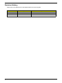
Revision History
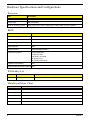
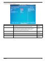
Please refer to the table below for the updates made on this service guide.
Date
ii
Chapter
Updates
Copyright
Copyright © 2010 by Acer Incorporated. All rights reserved. No part of this publication may be reproduced,
transmitted, transcribed, stored in a retrieval system, or translated into any language or computer language, in
any form or by any means, electronic, mechanical, magnetic, optical, chemical, manual or otherwise, without
the prior written permission of Acer Incorporated.
iii
Disclaimer
The information in this guide is subject to change without notice.
Acer Incorporated makes no representations or warranties, either expressed or implied, with respect to the
contents hereof and specifically disclaims any warranties of merchantability or fitness for any particular
purpose. Any Acer Incorporated software described in this manual is sold or licensed "as is". Should the
programs prove defective following their purchase, the buyer (and not Acer Incorporated, its distributor, or its
dealer) assumes the entire cost of all necessary servicing, repair, and any incidental or consequential
damages resulting from any defect in the software.
Acer is a registered trademark of Acer Corporation.
Intel is a registered trademark of Intel Corporation.
Pentium Dual-Core, Celeron Dual-Core, Core 2 Duo, Core 2 Quad, Celeron, and combinations thereof, are
trademarks of Intel Corporation.
Other brand and product names are trademarks and/or registered trademarks of their respective holders.
iv
Conventions
The following conventions are used in this manual:
SCREEN
MESSAGES
Denotes actual messages that appear on screen.
NOTE
Gives additional information related to the current topic.
WARNING
Alerts you to any physical risk or system damage that might result from doing
or not doing specific actions.
CAUTION
Gives precautionary measures to avoid possible hardware or software
problems.
IMPORTANT
Reminds you to do specific actions relevant to the accomplishment of
procedures.
v
Service Guide Coverage
This Service Guide provides you with all technical information relating to the BASIC CONFIGURATION
decided for Acer's "global" product offering. To better fit local market requirements and enhance product
competitiveness, your regional office MAY have decided to extend the functionality of a machine (e.g. add-on
card, modem, or extra memory capability). These LOCALIZED FEATURES will NOT be covered in this generic
service guide. In such cases, please contact your regional offices or the responsible personnel/channel to
provide you with further technical details.
FRU Information
Please note WHEN ORDERING FRU PARTS, that you should check the most up-to-date information available
on your regional web or channel. If, for whatever reason, a part number change is made, it will not be noted in
the printed Service Guide. For ACER-AUTHORIZED SERVICE PROVIDERS, your Acer office may have a
DIFFERENT part number code to those given in the FRU list of this printed Service Guide. You MUST use the
list provided by your regional Acer office to order FRU parts for repair and service of customer machines.
vi
Table of Contents
System Tour
Features
Block Diagram
System Components
Front Panel
Rear Panel
Hardware Specifications and Configurations
Power Management Function(ACPI support function)
System Utilities
CMOS Setup Utility
Entering CMOS setup
Navigating Through the Setup Utility
Setup Utility Menus
System Disassembly
Disassembly Requirements
Pre-disassembly Procedure
Removing the Side Panel
Removing the Heat Sink Fan Assembly
Removing the Processor
Removing the Memory Modules
Removing the VGA Card
Removing the Mode Card
Removing the Front Bezel
Removing the Rear USB Board
Removing the Hard Disk Drive
Removing the Optical Drive
Removing the Cables
Removing the removable HDD bay
Removing the Power Supply
Removing the Mainboard
System Troubleshooting
System Check Procedures
Beep Codes
Checkpoints
BIOS Recovery
Jumper and Connector Information
M/B Placement
Setting Jumper
FRU (Field Replaceable Unit) List
Aspire M5400(G) Exploded Diagram(AM350-ASSY)
Aspire M5400(G) Exploded Diagram(AM351-ASSY)
Aspire M5400(G) FRU List
1
1
4
5
5
6
7
11
12
12
13
13
14
27
27
28
29
30
32
33
34
35
36
37
38
40
41
42
43
45
47
48
49
50
53
54
54
56
67
68
69
70
vii
Chapter 1
System Tour
Features
Below is a brief summary of the computer’s many feature:
NOTE: The features listed in this section is for your reference only. The exact configuration of the system
depends on the model purchased.
Operating System
•
Microsoft Windows 7 Home Premium 64bit
•
Microsoft Windows 7 Home Premium 32bit
•
Microsoft Window 7 Home Basic 64bit
•
Microsoft Windows 7 Home Basic 32bit
•
Microsoft Windows 7 Starter 32bit
•
Microsoft Windows 7 Professional 32bit
•
Microsoft Windows XP Professional 32bit
•
Free DOS
•
Linpus XWindows 9.5
•
Lipus Linux cons
Processor
•
Socket Type: AMD Socket AM3
•
Socket Quantity: 1
•
Processor Type:
•
Support AM3 6-core Thuban CPU (140W)
Chipset
•
NB: RS880P
•
SB: AMD SB810
PCB
•
4 Layer uATX form factor 9.6in X 9.6in (24.38cm X 24.38cm)
Memory subsystem
•
Socket Type: DDR III Un-buffered DIMM connector
•
Socket Quantity: 4
•
•
2 channels, 2 DIMMs per channel.
Different colors for DIMM 0 and DIMM 1
•
1GB/2GB/4GB DDR3 1.5V 1333/1066 Un-buffered Non-ECC DIMM support
•
1 GB to 16GB Max memory support
•
Design Criteria:
Chapter 1
•
Must meet Intel Lynnfield and Clarkdale Chipset platform design guide
•
Support 1.5V DIMM
1
•
Dual channel should be enabled always when plug-in 2 same memory size DDRIII memory
module
Hard disk drive
•
Support up to two SATA ports
•
3.5"
•
Capacity and models are listed on AVLC
Optical disk drive
•
Support one SATA 5.25" standard ODD
•
Support DVD-ROM, DVD-SuperMulti, BD-combo, BD-rewrite
•
Maximum ODD depth to 185mm with bezel
•
Models are listed on AVLC
Graphics card
•
No mechanical retriction to support for double slot, full length graphics cards in the single PCIe X16 slot
Vedio
•
AMD RS880P on die graphic solution
•
Meet Microsoft Vista Premium graphic requirement
•
1 HDMI port and 1 D-sub port for Consumer model
•
1 D-sub port and 1 DVI-D port for Commercial model
•
Need to measure VGA follow Acer SOP
Audio
•
Chip : HD audio codec ALC662-VC HD codec 5.1
•
Connectors support:
•
Rear 3 jack follow HD audio definition (ALC662-VC)
•
Audio jacks color coding: should meet Microsoft Windows Logo Program Device Requirements:
Audio-0002
•
1 S/PDIF-out header (1*4)
•
1 front panel audio header (2*5)
•
1 internal speaker header (2*4)
•
Add HD de-pop CKT
Serial ATA controller
•
Slot Type: SATA connector
•
Six SATA ports:
•
2
•
4 for HDD
•
2 for ODD
Storage Type support:
•
1.HDD : Support RAID 0/1/5/10
•
2.Blue Ray ODD
•
3.AHCI mode supported for internal SATA port
Chapter 1
LAN
•
Controller: Realtek 8111E Gigabit Ethernet controller
•
RJ-45 Back panel port with Link/Activity LEDs
USB ports
•
Ports Quantity: 14 (should reserve more header for front DB)
•
6 ports for rear port
•
On-board: 4 2*5 headers
4 ports for front daughter board
2 ports for internal card reader
2 ports for Daughter board (Aspire M5400/M3400 only)
•
Connector Pin: standard Intel FPIO pin definition
Extension slot
•
Support one PCIe x 16 slot
•
Support two PCIe x 1 slots
•
Support one PCI slot
Rear I/O connectors
•
1 PS/2 Keyboard port
•
1 PS/2 Mouse port
•
1 HDMI port (need certification) for consumer models
•
1 D-sub port
•
1 DVI-D port for commercial models
•
6 USB ports
•
1 RJ45 LAN port
•
1 Com port for commercial models
•
5.1 channel phone jack (3 audio jacks)
On-board connectors
•
1 AM3 CPU socket
•
4 DDR3 memory sockets
•
1 PCI Express x16 slot
•
2 PCI Express x1 slot
•
1 PCI slots
•
6 SATA2 connectors
•
4 2x5-pin Intel FPIO specification USB pin connectors (follow Intel FPIO Standard Specification)
•
1 2x5-pin Intel FPIO spec Microphone In/ Headphone Out pin connector
•
1 1x4 S/PDIF out header (for ALC662 SKU)
•
1 3-pin CPU fan connector (co-lay with 4-pin CPU fan connector)
•
1 3-pin system fan connector with linear circuit
•
1 24-pin + 4-pin ATX interface PS3/PS2 SPS connector
•
1 2x7-pin front panel I/O header
•
1 Jumper for clear CMOS
•
1 on board buzzer
Chapter 1
3
•
2 reserved 2-pin GPIO connector
System BIOS
•
Size: 8Mbit
•
AMI Kernel with Acer skin/copyright
Power supply
4
•
300W/500W in stable mode (Acer Assign System Power Unit)
•
Support 82+ PSU for EnergyStar 5.0 complaint
•
Design for RS880P+SB810 series chipset compatible system
•
Voltage design should be covered +5V, +3.3V, +12V, +5VSB, -12V (attention to 12V output capability)
•
Demand for both PFC/Non-PFC solutions (two different quotations are needed)
•
PS2 style
Chapter 1
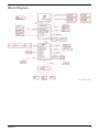
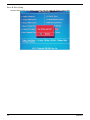
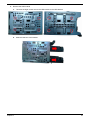
Block Diagram
Chapter 1
5
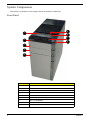
System Components
This section is a virtual tour of the system’s interior and exterior components.
Front Panel
9
1
8
7
2
6
3
4
5
6
No.
Component
1
USB 2.0 ports
2
Acer logo
3
Optical drive button
4
Optical drive button (Removable HDD bay for AM551 bezel)
5
Removable HDD bay
6
Power button
7
16 in 1 Card Reader
8
Headphone/Speaker-out/line-out jack
9
Microphone-in jack
Chapter 1
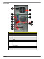
Rear Panel
1
14
2
13
3
12
4
5
11
10
9
6
7
8
No.
Chapter 1
Component
1
Power connector
2
PS2 keyboard port
3
HDMI port
4
VGA port
5
USB 2.0 ports
6
Mic-in
7
Line-out
8
Expansion slot (graphics card and TV tuner card and Mode card)
9
Line-in
10
USB 2.0 ports
11
LAN connector
12
System FAN
13
PS2 mouse port
14
Fan aperture
7
Hardware Specifications and Configurations
Processor
Item
Specification
Processor Type
Support AM3 6-core Thuban CPU (140W)
Socket Type
AMD Socket AM3
Minimum operating speed
0 MHz (If Stop CPU Clock in Sleep State in BIOS Setup is set to Enabled.)
BIOS
Item
Specification
BIOS code programer
AMI Kernel with Acer skin
BIOS version
P01-A0
BIOS ROM type
SPI ROM
BIOS ROM size
8Mb
Support protocol
SMBIOS(DMI)2.4/DMI2.0
Device Boot Support
Support BBS spec
1st priority: HDD
2nd priority: CD-ROM
3th priority: LAN
4th priority: USB device
Support to LS-120 drive
YES
Support to BIOS boot block feature YES
IOS Hotkey List
Hotkey
Function
Description
Del
Enter BIOS Setup Utility
Press while the system is booting to enter BIOS Setup Utility.
Main Board Major Chips
Item
Specification
North Bridge
RS880P
South Bridge
SB810
Audio controller
ALC662-VC
LAN controller
Realtek 8111E Gigabit Ethernet controller
HDD controller
RS880P
8
Chapter 1
Memory Combinations
Slot
Memory
Total Memory
Slot 1
1MB,2GB,4GB
1G ~4GB
Slot 2
1MB,2GB,4GB
1G ~4GB
Slot 3
1MB,2GB,4GB
1G ~4GB
Slot 4
1MB,2GB,4GB
1G ~4GB
Maximum System Memory Supported
1G~16GB
System Memory
Item
Specification
Memory slot number
4 slot
Support Memory size per socket
1GB/2GB/4GB
Support memory type
DDRIII
Support memory interface
DDRIII 1066/1333MHz
Support memory voltage
1.5V
Support memory module package
240-pin DDRIII
Support to parity check feature
Yes
Support to error correction code (ECC) feature No
Memory module combinations
You can install memory modules in any combination as long as
they match the above specifications.
Audio Interface
Item
Specification
Audio controller
ALC662-VC
Audio channel
codec 5.1
Audio function control
Enable/disable by BIOS Setup
Mono or stereo
Stereo
Compatibility
Support host audio controller from the Intel ICH series chipset, and also from
any other HDA compatible audio controller. With EAX/Direct Sound 3D/I3DL2/
A3D compatibility, and excellent software utilities like environment sound
emulation, multiple bands of software equalizer and dynamic range control,
optional Dolby, Digital Live, DTS CONNECT, and Dolby Home Theater
programs, provides an excellent home entertainment package and game
experience for PC users.
Sampling rate
192 KHz (max.)
Microphone/Headphone jack
Supported
Chapter 1
9
SATA Interface
Item
Specification
SATA controller
RS880P
Number of SATA channel
SATA X 6
Support mode
RAID/AHCI/IDE mode option
USB Port
Item
Specification
Universal HCI
USB 2.0/1.1
USB Class
Support legacy keyboard for legacy mode
USB Connectors Quantity
6 back real ports
4 ports for front daughter board
4 ports reserved
Environmental Requirements
Item
Specification
Temperature
Operating
+5°C ~ +35°C
Non-operating
-20 ~ +60°C (Storage package)
Humidity
Operating
15% to 80% RH
Non-operating
10% to 90% RH
Vibration
Operating (unpacked)
5 ~ 500 Hz: 2.20g RMS random, 10 minutes per axis in all 3 axes.
5 ~500 Hz: 1.09g RMS random, 1 hour per axis in all 3 axes.
Power Management
Devices
S1
S3
S4
S5
Power Button
V
V
V
V
USB Keyboard/Mouse
V
V
N/A
N/A
PME
Disabled
Disabled
Disabled
Disabled
RCT
Disabled
Disabled
Disabled
Disabled
WOR
Disabled
Disabled
Disabled
Disabled
10
•
Devices wake up from S3 should be less than.
•
Devices wake up from S5 should be less than 10 seconds.
Chapter 1
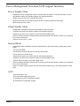
Power Management Function(ACPI support function)
Device Standby Mode
•
Independent power management timer for hard disk drive devices(0-15 minutes,time step=1minute).
•
Hard Disk drive goes into Standby mode(for ATA standard interface).
•
Disable V-sync to control the VESA DPMS monitor.
•
Resume method:device activated (keyboard for DOS, keyboard &mouse for Windows.
•
Resume recovery time 3-5sec
Global Standby Mode
•
Global power management timer(2-120minutes,time step=10minute).
•
Hard disk drive goes into Standby mode(for ATA standard interface).
•
Disable H-sync and V-sync signals to control the VESA DPMS monitor.
•
Resume method: Resume to original state by pushing external switch Button,modem ring in,keyboard
an mouse for APM mode.
Resume recovery time :7-10sec
•
Suspend Mode
•
Independent power management timer(2-120minutes,time step=10minute)or pushing extern switch
button.
CPU goes into SMM
•
•
CPU asserts STPCLK# and goes into the Stop Grant State.
•
LED on panel turns amber colour.
•
Hard disk drive goes into SLEEP mode (for ATA standard interface).
•
Disable H-sync and V-sync signals to control the VESA DPMS monitor.
•
Ultra I/O and VGA chip go into power saving mode.
•
Resume method: Resume to original state by pushing external switch Button,modem ring in,keyboard
an mouse for APM mode
•
Return to original state by pushing external switch button,modem ring in and USB keyboard for ACPI
mode.
ACPI
•
ACPI specification 1.0b
•
S0,S1,S2 and S5 sleep state support.
•
On board device power management support.
•
On board device configuration support.
Chapter 1
11
Chapter 2
System Utilities
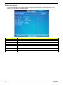
CMOS Setup Utility
CMOS setup is a hardware configuration program built into the system ROM, called the complementary metaloxide semiconductor (CMOS) Setup Utility. Since most systems are already properly configured and
optimized, there is no need to run this utility. You will need to run this utility under the following conditions.
•
When changing the system configuration settings
•
When redefining the communication ports to prevent any conflicts
•
When modifying the power management configuration
•
When changing the password or making other changes to the security setup
When a configuration error is detected by the system and you are prompted ("Run Setup"
message) to make changes to the CMOS setup
NOTE: If you repeatedly receive Run Setup messages, the battery may be bad. In this case, the system
cannot retain configuration values in CMOS. Ask a qualified technician for assistance.
•
CMOS setup loads the configuration values in a battery-backed nonvolatile memory called CMOS RAM. This
memory area is not part of the system RAM which allows configuration data to be retained when power is
turned off.
Before you run the CMOS Setup Utility, make sure that you have saved all open files. The system reboots
immediately after you close the Setup.
NOTE: CMOS Setup Utility will be simply referred to as “BIOS”, "Setup", or "Setup utility" in this guide.
The screenshots used in this guide display default system values. These values may not be the same
those found in your system.
Chapter 2
12
Entering CMOS setup
1.
Turn on the server and the monitor.
If the server is already turned on, close all open applications, then restart the server.
2.
During POST, press Delete.
If you fail to press Delete before POST is completed, you will need to restart the server.
The Setup Main menu will be displayed showing the Setup’s menu bar. Use the left and right arrow keys
to move between selections on the menu bar.
Navigating Through the Setup Utility
Use the following keys to move around the Setup utility.
•
Left and Right arrow keys – Move between selections on the menu bar.
•
Up and Down arrow keys – Move the cursor to the field you want.
•
PgUp and PgDn keys – Move the cursor to the previous and next page of a multiple page menu.
•
Home – Move the cursor to the first page of a multiple page menu.
•
End – Move the cursor to the last page of a multiple page menu.
+ and - keys – Select a value for the currently selected field (only if it is user-configurable). Press
these keys repeatedly to display each possible entry, or the Enter key to choose from a pop-up
menu.
NOTE: Grayed-out fields are not user-configurable.
•
•
Enter key – Display a submenu screen.
NOTE: Availability of submenu screen is indicated by a (>).
•
13
Esc – If you press this key:
•
On one of the primary menu screens, the Exit menu displays.
•
On a submenu screen, the previous screen displays.
•
When you are making selections from a pop-up menu, closes the pop-up without making a
selection.
•
F1 – Display the General Help panel.
•
F6 – Press to load optimized default system values.
•
F7 – Press to load fail-safe default system values.
•
F10 – Save changes made the Setup and close the utility.
Chapter 2
Setup Utility Menus
The Setup Main menu includes the following main setup categories.
Parameter
Description
Product Information
This page shows the relevant information of the main board
Standard CMOS Features
This setup page includes all the items in standard compatible BIOS
Advanced BIOS Features
This setup page includes all the items of Award special enhanced features
Advanced Chipset Features
This setup page includes all advanced chipset features
Integrated Peripherals
This setup page includes all onboard peripherals
Power Management Setup
This setup page includes all the items of Green function features
PC Health Status
This setup page is the System auto detect Temperature, voltage, and fan speed
Frequency/Voltage Control
This setup page is the System Frequency setup
BIOS Security Features
Change, set or disable password. It allows you to limit access to the System
Load Default Setting
Load Default Setting indicates the value of the system parameters which the system would be
in best performance configuration
Save & Exit Setup
Save CMOS value settings to CMOS and exit setup
Exit Without Saving
Abandon all CMOS value changes and exit setup
In the descriptive table following each of the menu screenshots, settings in boldface are the default and
suggested settings.
Chapter 2
14
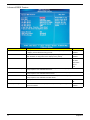
Product Information
The Product Information menu displays basic information about the system. These entries are for your
reference only and are not user-configurable.
Parameter
Description
Processor Type
Type of CPU installed on the system.
Processor Speed
Speed of the CPU installed on the system.
System Memory
Total size of system memory installed on the system.
Product Name
Product name of the system.
System Serial Number
Serial number of the system.
System BIOS Version
Version number of the BIOS setup utility.
BIOS Release Date
Date when the BIOS setup utility was released
Asset Tag Number
Asset tag number of this system.
15
Chapter 2
Standard CMOS Features
Parameter
Description
System Date
Set the date following the weekday-month-day-year format.
System Time
Set the system time following the hour-minute-second format.
Halt On
Determines whether the system will stop for an error during the POST.
Option
All, But Keyboard
No Errors
All Errors
Chapter 2
16
Advanced BIOS Feature
Parameter
Description
Option
Quick Boot
Allows you to decrease the time it takes to boot the computer by shortening
or skipping certain standard booting process.
Enabled
Quiet Boot
When enabled, the BIOS splash screen displays during startup.
Enabled
When disabled, the diagnostic screen displays during startup.
Disabled
Specifies the boot order from the available devices.
Hard Disk
1st/2nd/3rd/4th Boot Device
Disabled
CD^DVD
Removable
Device
LAN
Hard Disk Drive Priority
Press Enter to access the Hard Disk Drive Priority submenu and specify the boot device
priority sequence from available hard drives.
Optical Disk Drives Priority
Press Enter to access the Optical Disk Drive Priority submenu and specify the boot device
priority sequence from available CD/DVD drives.
Removable Device Priority
Press Enter to access the Removable Device Priority submenu and specify the boot device
priority sequence from available removable drives.
Bootup Num-Lock
Selects power on state for Num Lock.
USB Beep Message
Enables or disables BIOS to display error beeps or messages during USB
device enumeration.
On
Off
17
Disabled
Enabled
Chapter 2
Advanced Chipset Features
Parameter
Description
Option
AMD Cool’n’ Quiet
When enabled, this feature allows the OS to reduce power consumption.
Enabled
When disabled, the system operates at maximum CPU speed.
Disabled
Enables or disables the Virtualization Technology (VT) availability. If
enabled, a virtual machine manager (VMM) can utilize the additional
hardware virtualization capabilities provided by this technology.
Enabled
AMD-V
Disabled
Note: A full reset is required to change the setting.
ASF
Enables or disables ASF
Enabled
Disabled
Primary Video
Select a Video memory size
Auto
UMA Frame buffer Size
Select a Frame buffe size
Auto
Surround view
Enables or disables Surrande view
Enabled
Disabled
Chapter 2
18
Integrated Peripherals
Parameter
Description
Onboard SATA Controller
Enables or disables the onboard SATA controller.
Option
Enabled
Disabled
Onboard SATA Mode
Select an operating mode for the onboard SATA.
RAID
Native IDE
Onboard USB Controller
Enables or disables the onboard USB controller.
Enabled
Legacy USB Support
Enables or disables support for legacy USB devices.
Enabled
Disabled
Disabled
USB Storage Emulation
Enables or disables support for legacy USB devices.
Onboard Graphics Controller
Enables or disables the onboard USB controller.
Enabled
Disabled
Enabled
Disabled
Onboard Graphics Mode
select a mode of the onboard graphics
UMA
Onboard Audio Controller
Enables or disables the onboard audio controller.
Enabled
Disabled
Onboard LAN Controller
Enables or disables the onboard LAN controller.
Enabled
Onboard LAN Option ROM
Enables or disables the load of embedded option ROM for
onboard network controller.
Enabled
Onboard Floppy Controller
Enables or disables the onboard Floppy controller.
Enabled
Serial Port1 Address
select a port base on address
3F8/IRQ4
Serial Port1 Mode
select the mode
Normal
Serial Port2 Address
select a port base on address
2F8/IRQ3
Serial Port2 Mode
select the mode
Normal
Parallel Port Address
select a port base on address
378
Parallel Port Mode
select the mode
Normal
Disabled
Disabled
Disabled
19
Chapter 2
Power Management Setup
Parameter
Description
Option
ACPI Suspend Mode
Select an ACPI state.
S3 (STR)
Deep power off mode
Select the Deep power off Mode
S1 (POS)
Enabled
Disabled
Power On by RTC Alarm
Enables or Disables to wake up the system by RTC Alarm Function
Enabled
Power On by PCIE Devices
Enables or disables to wake up the system from a power saving mode
through an event on PCI Express device.
Enabled
Power On by PCI Devices
Enables or disables to wake up the system from a power saving mode
through an event on PCI device.
Enabled
Power On by Modem Ring
Enables or disables to wake up the system from a power saving mode
through Modem Ring.
Enabled
Wake Up by PS/2 KB/
Mouse
Enables or disables to wake up the system from a power saving mode
using a PS2 keyboard or mouse.
Enabled
Wake Up by USB KB/
Mouse
If enabled, press any key or click the mouse will wake system from S1/
S3 state.
Enabled
Restore On AC Power Loss
Enables or disables the system to reboot after a power failure or
interrupt occurs.
Power Off
Disabled
Disabled
Disabled
Disabled
Disabled
Disabled
Power On
Last State
Chapter 2
20
PC Health Status
Parameter
Description
system Shutdown
Temperature
Select the system Shutdown Temperature
CPU Shutdown Temperature
Select the system Shutdown Temperature
Option
Enabled
Disabled
Enabled
Disabled
Smart FAN
Enables or disables the smart system fan control function.
Enabled
Disabled
21
Chapter 2
Frequency/Voltage Control
Parameter
Description
Option
Spread Spectrum
Enables or disables the reduction of the mainboard’s EMI.
Enabled
Note: Remember to disable the Spread Spectrum feature if you are
overclocking. A slight jitter can introduce a temporary boost in clock
speed causing the overclocked processor to lock up.
Disabled
Chapter 2
22
BIOS Security Features
Parameter
Description
Supervisor Password
Indicates the status of the supervisor password.
User Password
Indicates the status of the user password.
Change Supervisor
Password
Supervisor password prevents unauthorized access to the BIOS Setup Utility.
Press Enter to change the Supervisor password.
Setting a supervisor password
1.
Use the up/down arrow keys to select Change Supervisor Password menu then press Enter.
A password box will appear.
2.
Type a password then press Enter.
The password may consist up to six alphanumeric characters (A-Z, a-z, 0-9)
3.
Retype the password to verify the first entry then press Enter again.
4.
Press F10.
5.
Select Yes to save the new password and close the Setup Utility.
Changing the supervisor password
1.
Use the up/down arrow keys to select Change Supervisor Password menu then press Enter.
2.
Type the original password then press Enter.
3.
Type a new password then press Enter.
4.
Retype the password to verify the first entry then press Enter again.
5.
Press F10.
6.
Select Yes to save the new password and close the Setup Utility.
Removing a supervisor password
23
1.
Use the up/down arrow keys to select Change Supervisor Password menu then press Enter.
2.
Enter the current password then press Enter.
3.
Press Enter twice without entering anything in the password fields.
Chapter 2
Load Default Settings
The Load Default Settings menu allows you to load the default settings for all BIOS setup parameters. Setup
defaults are quite demanding in terms of resources consumption. If you are using low-speed memory chips or
other kinds of low-performance components and you choose to load these settings, the system might not
function properly.
Chapter 2
24
Save & Exit Setup
The Save & Exit Setup menu allows you to save changes made and close the Setup Utility.
25
Chapter 2
Exit Without Saving
The Exit Without Saving menu allows you to discard changes made and close the Setup Utility.
Chapter 2
26
Chapter 3
System Disassembly
This chapter contains step-by-step procedures on how to disassemble the desktop computer for maintenance
and troubleshooting.
Disassembly Requirements
To disassemble the computer, you need the following tools:
•
Wrist grounding strap and conductive mat for preventing electrostatic discharge
•
Flat-blade screwdriver
•
Philips screwdriver
•
Hex screwdriver
•
Plastic flat-blade screwdriver
Plastic tweezers
NOTE: The screws for the different components vary in size. During the disassembly process, group the
screws with the corresponding components to avoid mismatch when putting back the components.
•
Chapter 3
27
Pre-disassembly Procedure
Before proceeding with the disassembly procedure, perform the steps listed below:
28
1.
Turn off the system and all the peripherals connected to it.
2.
Unplug the power cord from the power outlets.
3.
Unplug the power cord from the system.
4.
Unplug all peripheral cables from the system.
5.
Place the system unit on a flat, stable surface.
Chapter 3
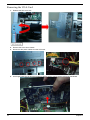
Removing the Side Panel
1.
Remove the two screws located on the rear edge of the side panel.
2.
Slide the side panel toward the back of the chassis until the tabs on the cover disengage with the slots on
the chassis.
3.
Lift the side panel away from the server and put it aside for reinstallation later.
Chapter 3
29
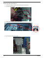
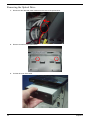
Removing the Heat Sink Fan Assembly
WARNING:The heat sink becomes very hot when the system is on. NEVER touch the heat sink with any metal
or with your hands.
30
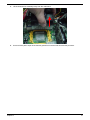
1.
Disconnect the fan cable from the mainboard.
2.
Use a long-nosed screwdriver to loosen the four screws on the heat sink, in the order as shown below.
Chapter 3
3.
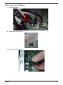
Lift the heat sink fan assembly away from the mainboard.
4.
Use an alcohol pad to wipe off the thermal grease from both the heat sink and the processor.
Chapter 3
31
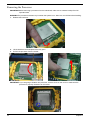
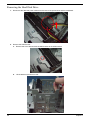
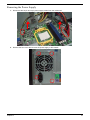
Removing the Processor
IMPORTANT:Before removing a processor from the mainboard, make sure to create a backup file of all
important data.
WARNING:The processor becomes very hot when the system is on. Allow it to cool off first before handling.
1.
Release the load lever.
2.
Lift the load lever and load plate to the fully open.
3.
Pull out the processor from the socket.
IMPORTANT: If you are going to install a new processor, note the arrow on the corner to make sure the
processor is properly oriented over the socket.
32
Chapter 3
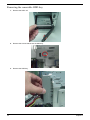
Removing the Memory Modules
IMPORTANT:Before removing any DIMM from the memory board, make sure to create a backup file of all
important data.
1.
Press the holding clips on both sides of the DIMM slot outward to release the DIMM(1,2).
2.
Gently pull the DIMM upward to pull it away from the M/B(3).
3
1
Chapter 3
2
33
Removing the VGA Card
34
1.
Release the Slot cover lock.
2.
Remove the screw from chassis.
3.
Disconnect the power cables from the VGA card.
4.
One finger Press the clip and the same time Gently pull the card to remove it from the mainboard.
Chapter 3
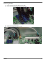
Removing the Mode Card
1.
Gently pull the Mode card to remove it from the mainboard.
Chapter 3
35
Removing the Front Bezel
36
1.
Remove the side panel. Refer to the previous section for instructions.
2.
Disconnect the LED cable.
3.
Release the front bezel from the chassis interior.
4.
Pull the bezel away from the chassis.
Chapter 3
Removing Rear USB Board
1.
Remove USB cable
2.
Release the screw of rear usb.
3.
Remove the rear usb board.
Chapter 3
37
Removing the Hard Disk Drive
38
1.
Disconnect the data and power cables from the rear of the optical drive and the mainboard.
2.
Remove the HDD bracket
a.
Remove the screw that secures the HDD bracket to the ODD bracket.
b.
Lift the bracket up and turn it over.
Chapter 3
3.
Remove the HDD module
a.
Remove the eight screws secure the HDD module to the HDD bracket.
b.
Slide the HDD out of the bracket.
Chapter 3
39
Removing the Optical Drive
40
1.
Disconnect the data and power cables from the rear of the optical drive.
2.
Remove screw from the optical drive.
3.
Pull the drive out of the drive.
Chapter 3
Removing Cables
1.
Remove power switch and LED cables from slot of M/B
2.
Remove HDD Data and ODD Data cables from slot of M/B.
3.
Remove USB1/2/3 cable from M/B.
4.
Remove FIO cable and Audio cable from M/B
Chapter 3
41
Removing the removable HDD bay
42
1.
Remove the HDD rail
2.
Remove the screws that secure the HDD bay.
3.
Remove the HDD bay.
Chapter 3
Removing the Power Supply
1.
Disconnect the 24-pin and 4-pin power supply cables from the mainboard.
2.
Remove the four screw that secures the power supply to the chassis.
Chapter 3
43
3.
44
Lift the power supply module out of the chassis.
Chapter 3
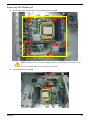
Removing the Mainboard
1.
Remove the eight screws that secure the mainboard to the chassis.
7
2
4
6
8
1
3
6
Note:Circuit boards >10 cm² has been highlighted with the yellow rectangle as above image
shows.
Please detach the Circuit boards and follow local regulations for disposal.
2.
Lift the board from the chassis.
Chapter 3
45
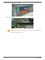
3.
Punching in IO Shield then you can remove it.
4.
Remove the RTC battery.
Note:RTC battery has been highlighted with the yellow circle as above image shows.Please detach the
RTC battery and follow local regulations for disposal.
46
Chapter 3
Chapter 4
System Troubleshooting
This chapter provides instructions on how to troubleshoot system hardware problems.
Hardware Diagnostic Procedure
IMPORTANT:The diagnostic tests described in this chapter are only intended to test Acer products. NonAcerproducts, prototype cards, or modified options can give false errors and invalid
systemresponses.
1.
Obtain the failing symptoms in as much detail as possible.
2.
Verify the symptoms by attempting to recreate the failure by running the diagnostic tests or repeating
thesame operation.
3.
Refer to “Power System check” and “Beep Codes” to determine which corrective action to perform.
Chapter 4
47
System Check Procedures
Power System Check
If the system will power on, skip this section. Refer to System External Inspection.
If the system will not power on, do the following:
•
Check if the power cable is properly connected to the system and AC source.
•
Check if the voltage selector switchis set to the correct voltage setting.
System External Inspection
1.
Inspect the LED indicators on the front panel, which can indicate the malfunction.
2.
Make sure that air flow is not blocked.
3.
Make sure nothing in the system is making contact that could short out power.
4.
If the problem is not evident, continue with System Internal Inspection.
System Internal Inspection
1.
Turn off the system and all the peripherals connected to it.
2.
Unplug the power cord from the power outlets.
3.
Unplug the power cord from the system.
4.
Unplug all peripheral cables from the system.
5.
Place the system unit on a flat, stable surface.
6.
Remove the system covers.For instructions on removing system covers, refer to “System Disassembly”.
7.
Verify that components are properly seated.
8.
Verify that all cable connectors inside the system are firmly and correctly attached to their appropriate
connectors.
9.
Verify that all components are Acer-qualified and supported.
10. Replace the system covers.
11. Power on the system.
12. If the problem with the system is not evident, you can try viewing the POST messages and BIOS event
logs during the system startup.
48
Chapter 4
Beep Codes
Beep codes are used by the BIOS to indicate a serious or fatal error to the end user. Beep codes are used
when an error occurs before the system video has been initialized. Beep codes will be generated by the
system board speaker, commonly referred to as the PC speaker.
AMIBIOS displays the checkpoints in the bottom right corner of the screen during POST. This display method
is limited, since it only displays checkpoints that occur after the video card has been activated.
Not all computers using AMIBIOS enable this feature. In most cases, a checkpoint card is the best tool for
viewing AMIBIOS checkpoints.
Beep Symptom
Cause and Description
One short beep
System is ready.
System is OK.
Continuous one long beep
Memory not installed or memory error.
One long beep and two short beeps then
repeat.
VGA not installed or VGA error.
Graphics card error/not installed, graphics card memory
error or graphics card BIOS checksum error.
One long beep then two short beep
BIOS damaged.
BIOS is damaged, BIOS POST jumps to Boot Block to
execute the default procedures.
Two short beeps
CMOS damaged.
CMOS checksum error or CMOS battery loss occurs.
Chapter 4
49
Checkpoints
A checkpoint is either a byte or word value output to I/O port 80h.The BIOS outputs checkpoints throughout
bootblock and Power-On Self Test (POST) to indicate the task the system is currently executing. Checkpoint
sare very useful in aiding software developers or technicians in debugging problems that occur during the preboot process.
Viewing BIOS checkpoints
Viewing all checkpoints generated by the BIOS requires acheckpoint card, also referred to as a POST card or
POST diagnostic card. These are ISA or PCI add-in cards that show the value of I/O port 80h on a LED
display. Checkpoints may appear on the bottom right corner of the screen during POST. This display method
islimited, since it only displays checkpoints thatoccur after the video card has been activated.
Bootblock Initialization Code Checkpoints
The Bootblock initialization code sets up the chipset,memory, and other components before system memory is
available. The following table describes the type of checkpoints that may occur during the bootblock
initialization portion of the BIOS.
NOTE: Please note that checkpoints may differ between different platforms based on system
configuration.Checkpoints may change due to vendor requirements,system chipset or option ROMs
from add-in PCI devices.
Checkpoint
Description
Before D0
If boot block debugger is enabled, CPU cache-as-RAM functionality is enabled at this point.
Stack will be enabled from this point.
D0
Early Boot Strap Processor (BSP) initialization like microcode update, frequency and other
CPU critical initialization. Early chipset initialization is done.
D1
Early super I/O initialization is done including RTC and keyboard controller. Serial port is
enabled at this point if needed for debugging. NMI is disabled. Perform keyboard controller
BAT test. Save power-on CPUID value in scratch CMOS. Go to flat mode with 4GB limit and
GA20 enabled.
D2
Verify the boot block checksum. System will hang here if checksum is bad.
D3
Disable CACHE before memory detection. Execute full memory sizing module. If memory
sizing module not executed, start memory refresh and do memory sizing in Boot block code.
Do additional chipset initialization. Re-enable CACHE. Verify that flat mode is enabled.
D4
Test base 512KB memory. Adjust policies and cache first 8MB. Set stack.
D5
Bootblock code is copied from ROM to lower system memory and control is given to it. BIOS
now executes out of RAM. Copies compressed boot block code to memory in right
segments. Copies BIOS from ROM to RAM for faster access. Performs main BIOS
checksum and updates recovery status accordingly.
D6
Both key sequence and OEM specific method is checked to determine if BIOSrecovery is
forced. Main BIOS checksum is tested. If BIOS recovery is necessary,control flows to
checkpoint E0. See Bootblock Recovery Code Checkpoints sectionfor more information.
D7
Restore CPUID value back into register. The Bootblock-Runtime interface module is moved
to system memory and control is given to it. Determine whether to execute serial flash.
D8
The Runtime module is uncompressed into memory. CPUID information is stored in memory.
D9
Store the Uncompressed pointer for future use in PMM. Copying Main BIOS into memory.
Leaves all RAM below 1MB Read-Write including E000 and F000 shadow areas but closing
SMRAM.
50
Chapter 4
Checkpoint
Description
DA
Restore CPUID value back into register. Give control to BIOS POST (ExecutePOSTKernel).
See POST Code Checkpoints section of document for more information.
DC
System is waking from ACPI S3 state.
E1-E8 ECEE
OEM memory detection/configuration error. This range is reserved for chipset vendors &
system manufacturers. The error associated with this value may be different from one
platform to the next.
Chapter 4
51
Bootblock Recovery Code Checkpoints
The Bootblock recovery code gets control when the BIOS determines that a BIOS recovery needs to occur
because the user has forced the update or the BIOS checksum is corrupt. The following table describes the
type of checkpoints that may occur during the Bootblock recovery portion of the BIOS.
NOTE: Checkpoints may differ between different platforms based on system configuration. Checkpoints
maychange due to vendor requirements, system chipset or option ROMs from add-in PCI devices.
Checkpoint
Description
E0
Initialize the floppy controller in the super I/O. Some interrupt vectors are initialized. DMA
controller is initialized. 8259 interrupt controller is initialized. L1 cache is enabled.
E9
Set up floppy controller and data. Attempt to read from floppy.
EA
Enable ATAPI hardware. Attempt to read from ARMD and ATAPI CDROM.
EB
Disable ATAPI hardware. Jump back to checkpoint E9.
EF
Read error occurred on media. Jump back to checkpoint EB.
F0
Search for pre-defined recovery file name in root directory.
F1
Recovery file not found.
F2
Start reading FAT table and analyze FAT to find the clusters occupied by the recovery file.
F3
Start reading the recovery file cluster by cluster.
F5
Disable L1 cache.
FA
Check the validity of the recovery file configuration to the current configuration of the flash
part.
FB
Make flash write enabled through chipset and OEM specific method. Detect proper flash
part. Verify that the found flash part size equals the recovery file size.
F4
The recovery file size does not equal the found flash part size.
FC
Erase the flash part
FD
Program the flash part.
FF
The flash has been updated successfully. Make flash write disabled. Disable ATAPI
hardware. Restore CPUID value back into register. Give control to F000 ROM at
F000:FFF0h.
52
Chapter 4
BIOS Recovery
1.
Copy the target BIOS rom file to a USB disk. Rename the target BIOS to “amiboot.rom”.Plug the USB disk
to computer that you want to recovery the system BIOS.
2.
Power on the system, BIOS recovery will be done. Wait for about 3 minutes the system will reboot
automatically after flash update completed successfully.
3.
Press “Del” Key to enter BIOS Setup.
4.
Choose “ Load Default Settings ” and press “ Enter ” key.
4-1.Choose “ OK ” and press “Enter ” key.
5.
Choose “Save & Exit Setup ” and press “Enter” key.
5-1.Choose “ OK ” and press “Enter ” key.
6.
AMIBIOS Recovery is finished.
Chapter 4
53
Chapter 5
Jumper and Connector Information
M/B Placement
Chapter 5
54
No
55
Label
Description
No
Label
Description
1
CPU Socket
AM3 938 socket for
CPU
2
PWR2
CPU Power
connector
3
CPU_FAN
CPU fan power
header
4
DIMM
CONN,DIMM,DDRIII,
1.5V,Blu,1mm,G/
F,G,DIP-240
5
MB_ID1~2
GPIO connector
6
PWR1
M/B main power
connector
7
SATA1~6
SATA data transfe
connector
8
F_PANEL
Front panel switch/
LED
9
F_USB2~4
Card reader USB
headers
10
F_USB1
Front panel USB
headers
11
SYS_FAN
SYS fan header
12
SPI
SPI header
?13
HBIOS_WP
BIOS write protect
header
14
CLR_CMOS
Clear CMOS jumpers
15
SPDIF_OUT
SPDIF out header
16
F_AUDIO
Front panel audio
header
17
PCI1
PCI socket
18
PCIE_1X1
PCIE_1x1 socket
19
PCIE_1X
PCIE_1x socket
20
PCI-E1_16X
PCIE_x16socket
Chapter 5
Jumper Setting
The section explains how to set jumper for correct configuration of the mainboard.
Setting Jumper
Use the motherboard jumpers to set system configuration options. Jumpers with more Than one pin are
numbered. When setting the jumpers, ensure that the jumper caps are Placed on the correct pins.
Internal header pin definition
Jumper/Header Name
Function
Definition
CPU FAN HEADER
1: SENSE
2: POWER
3: GND
SYS FAN HEADER
1: SENSE
2: POWER
3: GND
CPU_FAN (3 PIN)
Header_1X3
1
2
3
CPU_FAN
SYS_FAN (3 PIN)
Yellow is symbol, Red is Pin 1 of symbol.
CLEAR CMOS HEADER
1-2:CLEAR_CMOS
(1:Ground, 2:RTC_RSTJ)
2-3:NORMAL
(3:VCC_RTC)
CLR_CMOS (3 PIN)
Yellow is symbol, Red is Pin 1 of symbol.
Chapter 5
56
Jumper/Header Name
Function
Definition
System Recover HEADER
1:SYS_RECOVER
2: GND
OBR
Yellow is symbol, Red is Pin 1 of symbol.
F_USB1, F_USB2, F_USB3,
F_USB4
FRONT USB HEADER (2X5)
1. VCC5
2. VCC5
3. D14. D05. D1+
6. D0+
7. GND
8. GND
9. KEY
10. GND
Yellow is symbol, Red is Pin 1 of symbol.
FRONT PANEL AUDIO HEADER (2X5)
F_AUDIO
1: A_MIC2_L
2: GND_AUDIO
3: A_MIC2_R
4: FP_AUD_DETECT
5: A_LINE2_R
6: A_MIC2_JD
7: GND_AUDIO
8: KEY
9: A_LINE2_L
10: A_LINE2_JD
Yellow is symbol, Red is Pin 1 of symbol.
57
Chapter 5
Jumper/Header Name
Function
FRONT 1394 HEADER
F_1394
Definition
1. 1394_TPA0P_C
2. 1394_TPA0N_C
3. GND
4. GND
5. 1394_TPB0P_C
6. 1394_TPB0N_C
7. 1394_POW_CON_A
8. 1394_POW_CON_A
9. KEY
10. GND
Yellow is symbol, Red is Pin 1 of symbol.
Front panel header
F_PANEL
1: HDD+ (PU 5V_S0)
2: PWRLED_PN2(PU
5V_S5)
3: HDD_LED
4: PWRLED_PN4(PU
5V_S5)
5: GND
6: PANSWHJ_C
7: SYS_RSTJ
8: GND
9: FP_9(PU 5V_S0)
10: KEY
11: NC
12: FP_LANLED
13: NC
14: LAN_LED
Yellow is symbol, Red is Pin 1 of symbol.
TPM
Chapter 5
TPM Header
1: LCLK
2: GND
3: LFRAMEn
4: KEY
5: LRESETn
6: NC
7: LAD3
8: LAD2
9: VDD(3.3V)
10: LAD1 11: LAD0
12: GND
13: NC
14: NC
15: NC
16: SERIRQ
17: GND
18: CLKRUNin
19: LPCPDn
20: NC
58
Jumper/Header Name
Function
Printer Header
LPT
Definition
1: STRBJ
2: AFDJ
3: PRP_D0
4: PRERRJ
5:PRP_D1
6: INITJ
7: PRP_D2
8: SLINJ
9: PRP_D3
10: GND
11: PRP_D4
12: GND
13: PRP_D5
14: GND
15: PRP_D6
16: GND
17: PRP_D7
18: GND
19: PACKJ
20: GND
21: PBUSY
22: GND
23: PE
24: GND
25: PSLCT
26:NC
Yellow is symbol, Red is Pin 1 of symbol.
Audio internal speaker header
SPEAKER
1: MONO_L
2: GND
3: MONO_R
4: KEY
5: GND
6: GND
7: VCC3
8: VCC5
Yellow is symbol, Red is Pin 1 of symbol.
59
Chapter 5
Jumper/Header Name
Function
Definition
1: VCC (5V_SYS)
2: KEY
3: A_SPDIF_OUT1
4: GND
SPDIF_OUT, SPDIF_OUT1
Yellow is symbol, Red is Pin 1 of symbol.
1. JDCD2J
2. JSIN2
3. JSOUT2
4. JDTR2J
5. GND
6. JDSR2J
7. JRTS2J
8. JCTS2J
9. JRI2J
10. KEY
COM2
COM2
1
3
5
7
9
2
4
6
8
X
Header_2X5_K10
@Commercial
Yellow is symbol, Red is Pin 1 of symbol.
Chapter 5
60
USB CONNECTORS (Stacked)(Black)
USB_X4
Pin
61
Signal Name
"11,21,31,41"
VCC_USB1
12
USBP3N_R
13
USBP3P_R
14
Ground
22
USBP2N_R
23
USBP2P_R
24
Ground
32
USBP5N_R
33
USBP5P_R
34
Ground
42
USBP4N_R
43
USBP4P_R
44
Ground
"45,46,47,48,
49,50"
Ground
Chapter 5
11.2.2LAN-USB_X2
Pin
Signal Name
"1, 5"
VCC_USB0 (5V)
2
USBP7N_R
3
USBP6N_R
"4, 8"
GND
6
USBP6N_R
7
USBP6P_R
"23,24,25,26,
27,28,29,30"
Ground
9
AVDD18
10
MDI0+
11
MDI0-
12
MDI1+
13
MDI1-
14
MDI2+
15
MDI2-
16
MDI3+
17
MDI3-
18
GND
19
ACT_LED
20
LAN_LINK_LED
21
100_LED
22
1G_LED
NOTE: Pins 9-18 for RJ-45 LAN Jack pin definition, 19-22 for LAN LED definition
Chapter 5
62
Audio Back Panel Connectors
AUDIO1A (MIC)
Pin
Signal Name
1
GND_AUDIO
2
A_MIC1_L
3
A_MIC1_JD
4
GND_AUDIO
5
A_MIC1_R
AUDIO1B (Line in)
Pin
Signal Name
31
GND_AUDIO
32
A_LOUT_L
33
A_LOUT_JD
34
GND_AUDIO
35
A_LOUT_R
AUDIO1C (Line out)
Pin
Signal Name
21
GND_AUDIO
22
A_LINE1_L
23
A_LINE1_JD
24
GND_AUDIO
25
A_LINE1_R
IDE / SATA
40-pin (2x20) IDE Headers
Pin
63
Signal Name
Pin
Signal Name
1
IDERST
2
Ground
3
PIDE_D7
4
PIDE_D8
5
PIDE_D 6
6
PIDE_D 9
7
PIDE_D 5
8
PIDE_D 10
9
PIDE_D 4
10
PIDE_D 11
11
PIDE_D 3
12
PIDE_D 12
13
PIDE_D 2
14
PIDE_D 13
15
PIDE_D 1
16
PIDE_D 14
17
PIDE_D 0
18
PIDE_D 15
19
Ground
20
Key
21
PIDE_DREQ
22
Ground
23
PIDE_IOWJ
24
Ground
25
PIDE_IORJ
26
Ground
27
PIDE_RDY
28
Ground
29
PIDE_PACKJ
30
Ground
31
PIDE_IRQ
32
N/C
Chapter 5
Pin
Signal Name
Pin
Signal Name
33
PIDE_A1
34
PD_DMA66
35
PIDE_A0
36
PIDE_A2
37
PIDE_CS1J
38
PIDE_CS3J
39
PATA_LEDJ
40
Ground
1x7-pin SATA Headers
Pin
Signal Name
1
GND
2
SATA_TX0+_
3
SATA_TX0-_C
4
GND
5
SATA_RX0-_C
6
SATA_RX0+_C
7
GND
8
KEY
9
KEY
VGA
Pin
Signal Name
1
R
2
G
3
B
4
ID0
5
GND
6
GND
7
GND
8
GND
9
NC (5V_VGA)
10
GND
11
ID1
12
SDA
13
HSYNC
14
VSYNC
15
SCL
HDMI
Pin
Chapter 5
Signal Name
1
HDMI_TXDP2_C
2
GND
64
Pin
Signal Name
3
HDMI_TXDN2_C
4
HDMI_TXDP1_C
5
GND
6
HDMI_TXDN1_C
7
HDMI_TXDP0_C
8
GND
9
HDMI_TXDN0_C
10
HDMI_TXCP_C
11
GND
12
HDMI_TXCN_C
13
NC
14
NC
15
HDMI_DDCCLK_C
16
HDMI_DDCDATA_C
17
GND
18
5V_HDMI_C
19
HP_DET_C
20
GND
21
GND
DVI-D
Pin
Signal Name
Pin
Signal Name
1
DVI_TXDN2_C
13
NC
2
DVI_TXDP2_C
14
5V_HDMI_C
3
GND
15
GND
4
NC
16
HP_DET_C
5
NC
17
DVI_TXDN0_C
6
HDMI_DDCCLK_C
18
DVI_TXDP0_C
7
HDMI_DDCDATA_C
19
GND
8
NC
20
NC
9
DVI_TXDN1_C
21
NC
10
DVI_TXDP1_C
22
GND
11
GND
23
DVI_TXCP_C
12
NC
24
DVI_TXCN_C
PS2
Pin
65
Signal Name
Pin
Signal Name
1
KB_DA
10
KBVCC (5V_DUAL)
2
NC
11
MS_CK
3
GND
12
NC
4
KBVCC (5V_DUAL)
13
GND
5
KB_CK
14
GND
6
NC
15
GND
Chapter 5
Pin
Signal Name
Pin
Signal Name
7
MS_DA
16
GND
8
NC
17
GND
9
GND
COM
Pin
Chapter 5
Signal Name
1
JDCD1J
2
JSIN1
3
JSOUT1
4
JDTR1J
5,10,11
GND
6
JDSR1J
7
JRTS1J
8
JCTS1J
9
JRI1J
66
Chapter 6
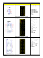
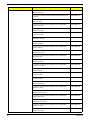
FRU (Field Replaceable Unit) List
This chapter offers the FRU (Field Replaceable Unit) list in global configuration of the Aspire M5400(G)
desktop computer. Refer to this chapter whenever ordering the parts to repair or for RMA (Return Merchandise
Authorization).
NOTES:
chapter 6
•
When ordering FRU parts, check the most up-to-date information available on your regional web
or channel. For whatever reasons a part number is changed, it will NOT be noted on the printed
Service Guide. For Acer authorized service providers, your Acer office may have a different part
number code from those given in the FRU list of this printed Service Guide. You MUST use the
local FRU list provided by your regional Acer office to order FRU parts for service.
•
To scrap or to return the defective parts, follow the local government ordinance or regulations on
how to dispose it properly, or follow the rules set by your regional Acer office on how to return it.
•
This document will be updated as more information about the FRU list becomes available.
67
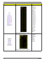
Aspire M5400(G) Exploded Diagram(AM551 ASSY)
NOTE: This section will be updated when more information becomes available.
ITEM
NAME
Q’TY
ITEM
NAME
Q’TY
1
CHASSIS ASM
1
5
FRONT BEZEL
1
2
TOP-COVER
1
6
HDD COVER
1
3
ODD
1
7
SIDE COVER
1
4
REMOVABLE HDD CARRIER
2
8
POWER
1
68
Chapter 6
Aspire M5400(G) Exploded Diagram(AM550 ASSY)
NOTE: This section will be updated when more information becomes available.
ITEM
NAME
Q’TY
ITEM
NAME
Q’TY
1
CHASSIS ASM
1
5
FRONT BEZEL
1
2
TOP-COVER
1
6
HDD COVER
1
3
ODD
1
7
SIDE COVER
1
4
REMOVABLE HDD CARRIER
2
8
POWER
1
Chapter 6
69
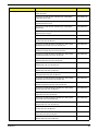
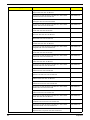
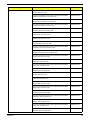
Aspire M5400(G) FRU List
Category
Part Number
Acer P/N
MB Kit
Mainboard FRS880F consumer
MB.SE109.001
Mainboard FRS880F consumer Support 140W CPU
MB.SE109.003
Rear I/O Shielding for MB
TBD
Micro-Tower chassis HM090H for AM550
HS.13100.117
Micro-Tower chassis HM090K for AM551
HS.13100.124
Aspire Bezel AM550
PZ.11900.175
Aspire Bezel AM551
PZ.11900.182
Fan Cooler K8_M2 FXC PKP482 Fan8025
HI.12900.026
Fan Cooler K8_M2 AVC Z7UB008 AVC fan7015
HI.12900.001
Cooler AMD AVC Z8UH408002 (for 125W/140W)
HI.12900.021
System Fan KDE 1209/GP 92*92*25 (Rohs)
HI.S150F.002
AMD Phenom II 965
KC.PM202.965
AMD Phenom II 955
KC.PM202.955
AMD Phenom II B95
KC.PH202.B95
AMD Phenom II 740
KC.PH202.740
AMD Phenom II 720
KC.PH202.720
AMD Phenom II B75
KC.PH202.B75
IO Shielding
Chassis
Bezel
CPU Cooler
System Fan
CPU
70
Chapter 6
Category
Part Number
Acer P/N
AMD Phenom II 555
KC.PH202.555
AMD Phenom II 550
KC.PM202.550
AMD Phenom II B55
KC.PH202.B55
AMD Athlon II x4 640
KC.AM202.640
AMD Athlon II x4 635
KC.AM202.635
AMD Athlon II x4 605e
KC.AE202.605
AMD Athlon II x3 445
KC.AM202.445
AMD Athlon II x3 440
KC.AM202.440
AMD Athlon II x2 255
KC.AT202.255
AMD Athlon II x2 250
KC.AT202.250
AMD Athlon II x2 B24
KC.AT202.B24
AMD Athlon II 160u
KC.AU202.160
SEMPRON 140
KC.SMP02.140
DDRIII 1333MHz 1GB
KN.1GB0H.015
DDRIII 1333MHz 1GB
TBD
DDRIII 1333MHz 1GB
KN.1GB0B.030
DDRIII 1333MHz 1GB
KN.1GB0B.036
DDRIII 1333MHz 1GB
TBD
DDRIII 1333MHz 1GB
KN.1GB01.031
DDRIII 1333MHz 1GB
KN.1GB07.002
DDRIII 1333MHz 1GB
KN.1GB0C.008
DDRIII 1333MHz 1GB
KN.1GB0F.005
DDRIII 1333MHz 2GB
KN.2GB0H.009
DDRIII 1333MHz 2GB
KN.2GB03.018
DDRIII 1333MHz 2GB
KN.2GB0B.014
DDRIII 1333MHz 2GB
KN.2GB0B.024
DDRIII 1333MHz 2GB
TBD
DDRIII 1333MHz 2GB
KN.2GB01.025
DDRIII 1333MHz 2GB
KN.2GB07.002
DDRIII 1333MHz 2GB
KN.2GB0C.005
DDRIII 1333MHz 2GB
KN.2GB0F.004
DDRIII 1333MHz 4GB
TBD
DDRIII 1333MHz 4GB
TBD
DDRIII 1333MHz 4GB
TBD
DDRIII 1333MHz 4GB
TBD
Memory
Chapter 6
71
Category
Part Number
Acer P/N
HDD
HDD HGST 3.5" 7200rpm 160GB HDT721016SLA380
Saturn SATA II LF F/W:31B
KH.16007.023
HDD HGST 3.5" 7200rpm 160GB Jupiter
KH.16007.027
HDD HGST 3.5" 7200rpm 320GB HDT721032SLA380
Saturn SATA II LF F/W:31B
KH.32007.006
HDD HGST 3.5" 7200rpm 320GB Jupiter
KH.32007.011
HDD HGST 3.5" 7200rpm 500GB Jupiter
KH.50007.012
HDD HGST 3.5" 7200rpm 640GB Satum SATA II LF
KH.64007.001
HDD HGST 3.5" 7200rpm 640GB Jupiter
KH.64007.002
HDD HGST 3.5" 7200rpm 1000GB HDT721010SLA360
Saturn SATA II 16MB LF F/W:31B
KH.01K07.002
HDD HGST 3.5" 7200rpm 1000GB Jupiter
KH.01K07.003
HDD SEAGATE 3.5" 7200rpm 160G
KH.16001.041
HDD SEAGATE 3.5" 7200rpm 320G
KH.32001.015
HDD SEAGATE 3.5" 7200rpm 500G
KH.50001.012
HDD SEAGATE 3.5" 7200rpm 640G
KH.64001.002
HDD SEAGATE 3.5" 7200rpm 1000G
KH.01K01.007
HDD SEAGATE 3.5" 7200rpm 1500G
KH.15K01.002
HDD WD 3.5" 7200rpm 160G
KH.16008.025
HDD WD 3.5" 7200rpm 320G
KH.32008.016
HDD WD 3.5" 7200rpm 500G
KH.50008.014
HDD WD 3.5" 7200rpm 640G
KH.64008.003
HDD WD 3.5" 7200rpm 750G
KH.75008.005
HDD WD 3.5" 7200rpm 1000G
KH.01K08.004
HDD WD 3.5" 5400rpm 1000G
KH.01K08.005
HDD WD 3.5" 5400rpm 1000G
KH.01K08.008
HDD WD 3.5" 5400rpm 1500G
KH.15K08.001
HDD WD 3.5" 5400rpm 2000G
KH.02K08.001
ODD HLDS DVD-ROM HH 16X DH20N LF+HF Black Bezel
SATA w/Win7
KV.0160D.016
ODD PLDS DVD-ROM HH DL 16X DH-16D5SH LF+HF
Black Bezel SATA w/Win7
KV.0160F.002
ODD TSST DVD-ROM w/Win7
KV.01601.001
ODD HLDS Super-Multi DRIVE HH 16X GH41N Black Bezel
SATA HF + Win 7
KU.0160D.049
ODD PLDS Super-Multi DRIVE HH 16X DH-16AASH Black
Bezel SATA HF+Win7
KU.0160F.009
ODD
72
Chapter 6
Category
Part Number
Acer P/N
ODD TSST Super-Multi with LF
KU.01601.007
ODD PLDS BD ROM HH DL 4X DH-4O3S LF Standard
Bezel SATA
KV.0040F.002
ODD HLDS BD COMBO HH 6X CH-20N (H/F) Black Bezel
SATA w/ WIN7
KO.0060D.005
ODD PLDS BD COMBO HH 6X DH-6E2S Black Bezel SATA
w/ Win 7
KO.0060F.002
ODD HLDS BD RW HH 6X BH30N Black Bezel SATA HF
+Win7
KU.0060D.004
ODD HLDS BD RW HH 6X BH20F Black Bezel SATA (Win7
FW)
KU.0060D.005
288-1N143-010AC NV GT340 1GB DDR5 DVI+HDMI+VGA
ATX (HYNIX)
VG.PCPT3.401
288-1N143-110AC GEFORCE GT340 1GB GDDR5
SAMSUNG (128BITS) VGA DVI HDMI ATX BRACKET
ROHS
VG.PCPT3.402
288-30N58-010AC NV GT330 2GB DDR2 DVI+HDMI+VGA
ATX (SAMSUNG)
VG.PCPT3.301
288-30N58-110AC NV GT330 2GB DDR2 DVI+HDMI+VGA
ATX (HYNIX)
VG.PCPT3.302
288-5N118-010AC NV GT320 1GB sDDR3 DVI+HDMI+VGA
ATX (SAMSUNG)
VG.PCPT3.201
288-5N118-110AC NV GT320 1GB sDDR3 DVI+HDMI+VGA
ATX (HYNIX)
VG.PCPT3.202
288-6N118-010AC GEFORCE GT320 1GB DDR3
SAMSUNG (128BITS) VGA DVI HDMI ATX BRACKET
ROHS WITH CU COOLER
VG.PCPT3.221
288-1N141-A00AC NV 315 512MB sDDR3 DVI+HDMI ATX
(SAMSUNG)
VG.PCPT3.153
288-1N141-000AC NV 315 512MB sDDR3 DVI+HDMI+VGA
ATX (SAMSUNG)
VG.PCPT3.151
288-1N141-000AC NV 315 512MB sDDR3 DVI+HDMI+VGA
ATX (HYNIX)
VG.PCPT3.152
288-40N44-020AC GEFORCE 310 512MB DDR2
SAMSUNG (64BITS) VGA DVI HDMI ATX BRACKET ROHS
VG.PCPT3.101
288-40N44-120AC GEFORCE 310 512MB DDR2 HYNIX
(64BITS) VGA DVI HDMI ATX BRACKET ROHS
VG.PCPT3.102
HD5750 1GB GDDR 5 (128BITS) HYNIX DVI DVI HDMI DP
W/ATX BKT ROHS
VG.APC57.501
288-1E160-000AC HD5750 1GB GDDR 5 (128BITS)
SAMSUNG DVI HDMI VGA W/ATX BKT ROHS
VG.APC57.502
288-2E142-100AC HD5570 1GB DDR3 (128BITS) Hynix DVI
HDMI VGA W/ATX BKT ROHS
VG.APC55.702
288-2E142-100AC HD5570 1GB DDR3 (128BITS) Samsung
DVI HDMI VGA W/ATX BKT ROHS
VG.APC55.701
VGA
Chapter 6
73
Category
Part Number
Acer P/N
ATI HD4650 1GB DSUB/HDMI/DVI ATX
VG.APC46.501
288-1E127-010AC HD5450 512MB SDDR 3 (64BITS)
SAMSUNG DUAL DVI PASSIVE W/ATX BKT ROHS
VG.APC54.5P1
288-1E127-110AC HD5450 512MB SDDR 3 (64BITS)
HYNIX DUAL DVI PASSIVE W/ATX BKT ROHS
VG.APC54.5P2
288-1E145-A01AC HD5450 512MB SDDR 3 (64BITS)
SAMSUNG DVI HDMI W/LP BKT ROHS
VG.APC54.511
288-1E145-001AC HD5450 512MB SDDR 3 (64BITS)
SAMSUNG DVI HDMI VGA W/ATX BKT ROHS
VG.APC54.501
288-1E145-101AC HD5450 512MB SDDR 3 (64BITS)
HYNIX DVI HDMI VGA W/ATX BKT ROHS
VG.APC54.502
AMD RADEON HD5450 512MB (64BIT) DDR3 DVI HDMI
VGA ATX BRACKET ROHS
VG.ECS54.501
Avermedia H751-A TV Tuner Card PCIe Hybrid ATSC, S/W
Encoder
TU.10500.045
Avermedia H751-D TV Tuner Card PCIe Hybrid DVB-T, S/W
Encoder
TU.10500.048
16-in-1 CR Reealtek RTS-5181, 720mm USB cable for 2010
M5
CR.10400.116
16-in-1 CR RI236 UT330-LK, 720mm USB cable for 2010 M5
CR.10400.115
D-1156I#/A7A, Modem PCI card, LSI Universal Modem (PCI)
56K V.92 - Pinball (P40)
FX.10100.004
WN7600R, WLAN PCI-Ex1 card 802.11 b/g/n 1T x 2R, Ralink
1T x 2R, RT2790+RT2720
NI.10200.008
WN7601R, Ralink RT3090, 802.11b/g/n 1x1 WLAN PCI-E x1
card
NI.10200.037
TV-Tuner
Card Reader
Modem
WLAN
74
Chapter 6
Category
Part Number
Acer P/N
Power Supply
Non-PFC 250W (30L) EuP
PY.25009.014
Non-PFC 250W (30L) EuP
PY.25008.031
PFC 250W (30L) EuP
PY.25009.015
PFC 250W (30L) EuP
PY.25008.032
Non-PFC 300W (30L) EuP
PY.3000B.015
Non-PFC 300W (30L) EuP
PY.30008.028
FR 300W (30L) 82+ EuP
PY.30009.019
FR 300W (30L) 82+ EuP
PY.30008.029
FR 500W (30L) 82+ EuP
PY.50008.004
FR 500W (30L) 82+ EuP
PY.5000B.003
Acer 0810 Project PS2 Optical mouse
MS.11200.013
Logitech 0810_USB Optical mouse USB M-UAY-ACR2
MS.11200.014
Lite-On PS2 optical mouse PS2 SM-9620
MS.11200.017
Lite-On USB optical USB SM-9625
MS.11200.018
Lite-on Optical mouse USB SM-9625S with new color ACMT-018
MS.11200.048
Chicony RF2.4G mouse RF2.4G MG-0766
MS.11200.015
Chicony 2.4G Dangle Receiver external receiver
RV.11000.010
Neosonica Speaker Acer logo /LF /0810 / 9M-20A200-000
SP.10600.011
Neosonica Speaker USB with new color AC-MT-018
SP.10600.027
Philips Remote Controller RC2604307/01BG for EMEA ;pair
with RV.11000.007
RT.11300.021
Philips Vista receiver OVU71
RV.11000.007
Philips Remote Controller RC2604301/01B MSFT code
EMEA;pair with OVU430008
RT.11300.023
Philips Remote Controller RC2604302/01B MSFT code
US;pair with OVU430008
RT.11300.022
Philips Win7 OVU430008 with IR blaster
RV.11000.023
SMK Transceiver Win7 RXX6000-4111E with IR Blaster
RV.11000.024
SMK Remote Controller US RRS9003-3406E SMK Quatro
Pulse;with Battery Pack
RT.11300.025
Mouse
Speaker
Remote control
Chapter 6
75
Category
Part Number
Acer P/N
SMK Remote Controller Japan RRS9003-3407EC Quatro
Pulse
RT.11300.026
Keyboard CHICONY KG-0766 RF2.4 Standard 104KS Black
US w/o Aspire logo
KB.RF403.061
Keyboard CHICONY KG-0766 RF2.4 Standard 104KS Black
Traditional Chinese w/o Aspire logo
KB.RF403.062
Keyboard CHICONY KG-0766 RF2.4 Standard 104KS Black
Simplified Chinese w/o Aspire logo
KB.RF403.063
Keyboard CHICONY KG-0766 RF2.4 Standard 104KS Black
US International w/o Aspire logo
KB.RF403.064
Keyboard CHICONY KG-0766 RF2.4 Standard 104KS Black
Arabic/English w/o Aspire logo
KB.RF403.065
Keyboard CHICONY KG-0766 RF2.4 Standard 104KS Black
Thailand w/o Aspire logo
KB.RF403.066
Keyboard CHICONY KG-0766 RF2.4 Standard 105KS Black
Spanish w/o Aspire logo
KB.RF403.067
Keyboard CHICONY KG-0766 RF2.4 Standard 105KS Black
Portuguese w/o Aspire logo
KB.RF403.068
Keyboard CHICONY KG-0766 RF2.4 Standard 105KS Black
Canadian French w/o Aspire logo
KB.RF403.069
Keyboard CHICONY KG-0766 RF2.4 Standard 107KS Black
Brazilian Portuguese w/o Aspire logo
KB.RF403.070
Keyboard CHICONY KG-0766 RF2.4 Standard 105KS Black
German w/o Aspire logo
KB.RF403.072
Keyboard CHICONY KG-0766 RF2.4 Standard 105KS Black
Italian w/o Aspire logo
KB.RF403.073
Keyboard CHICONY KG-0766 RF2.4 Standard 105KS Black
French w/o Aspire logo
KB.RF403.074
Keyboard CHICONY KG-0766 RF2.4 Standard 105KS Black
Swedish w/o Aspire logo
KB.RF403.075
Keyboard CHICONY KG-0766 RF2.4 Standard 105KS Black
UK w/o Aspire logo
KB.RF403.076
Keyboard CHICONY KG-0766 RF2.4 Standard 105KS Black
Dutch w/o Aspire logo
KB.RF403.077
Keyboard CHICONY KG-0766 RF2.4 Standard 105KS Black
Swiss/G w/o Aspire logo
KB.RF403.078
Keyboard CHICONY KG-0766 RF2.4 Standard 105KS Black
Belgium w/o Aspire logo
KB.RF403.079
Keyboard CHICONY KG-0766 RF2.4 Standard 105KS Black
Icelandic w/o Aspire logo
KB.RF403.080
Keyboard CHICONY KG-0766 RF2.4 Standard 105KS Black
Norwegian w/o Aspire logo
KB.RF403.081
Keyboard CHICONY KG-0766 RF2.4 Standard 104KS Black
Hebrew w/o Aspire logo
KB.RF403.082
Keyboard
76
Chapter 6
Category
Chapter 6
Part Number
Acer P/N
Keyboard CHICONY KG-0766 RF2.4 Standard 105KS Black
Polish w/o Aspire logo
KB.RF403.083
Keyboard CHICONY KG-0766 RF2.4 Standard 105KS Black
Slovenian w/o Aspire logo
KB.RF403.084
Keyboard CHICONY KG-0766 RF2.4 Standard 105KS Black
Slovak w/o Aspire logo
KB.RF403.085
Keyboard CHICONY KG-0766 RF2.4 Standard 104KS Black
Russian w/o Aspire logo
KB.RF403.086
Keyboard CHICONY KG-0766 RF2.4 Standard 105KS Black
Hungarian w/o Aspire logo
KB.RF403.087
Keyboard CHICONY KG-0766 RF2.4 Standard 104KS Black
Greek w/o Aspire logo
KB.RF403.088
Keyboard CHICONY KG-0766 RF2.4 Standard 105KS Black
Danish w/o Aspire logo
KB.RF403.089
Keyboard CHICONY KG-0766 RF2.4 Standard 104KS Black
Czech w/o Aspire logo
KB.RF403.090
Keyboard CHICONY KG-0766 RF2.4 Standard 105KS Black
Romanian w/o Aspire logo
KB.RF403.091
Keyboard CHICONY KG-0766 RF2.4 Standard 105KS Black
Turkish w/o Aspire logo
KB.RF403.092
Keyboard CHICONY KG-0766 RF2.4 Standard 105KS Black
Spanish Latin w/o Aspire logo
KB.RF403.093
Keyboard CHICONY KG-0766 RF2.4 Standard 105KS Black
Turkish-Q w/o Aspire logo
KB.RF403.094
Keyboard CHICONY KG-0766 RF2.4 Standard 105KS Black
Nordic w/o Aspire logo
KB.RF403.095
Keyboard CHICONY KG-0766 RF2.4 Standard 105KS Black
Czech/Slovak
KB.RF403.285
Keyboard CHICONY KG-0766 RF2.4 Standard 105KS Black
English/Canadian French w/o Aspire logo
KB.RF403.288
Keyboard CHICONY KG-0766 RF2.4 Standard 105KS Black
Arabic/French w/o Aspire logo
KB.RF403.521
Keyboard CHICONY KG-0766 RF2.4 Standard 105KS Black
Kazakh w/o Aspire logo
KB.RF403.522
Keyboard CHICONY KG-0766 RF2.4 Standard 104KS Black
Turkmen w/o Aspire logo
KB.RF403.523
Keyboard CHICONY KG-0766 RF2.4 Standard 109KS
Japanese with J1 layout
KB.RF403.283
Keyboard CHICONY KB-0759 PS/2 Standard 104KS Black
US w/o eKey
KB.PS203.284
Keyboard CHICONY KB-0759 PS/2 Standard 104KS Black
Traditional Chinese w/o eKey
KB.PS203.285
Keyboard CHICONY KB-0759 PS/2 Standard 104KS Black
Simplified Chinese w/o eKey
KB.PS203.286
77
Category
78
Part Number
Acer P/N
Keyboard CHICONY KB-0759 PS/2 Standard 104KS Black
US International w/o eKey
KB.PS203.287
Keyboard CHICONY KB-0759 PS/2 Standard 104KS Black
Arabic/English w/o eKey
KB.PS203.288
Keyboard CHICONY KB-0759 PS/2 Standard 104KS Black
Thailand w/o eKey
KB.PS203.289
Keyboard CHICONY KB-0759 PS/2 Standard 105KS Black
Spanish w/o eKey
KB.PS203.290
Keyboard CHICONY KB-0759 PS/2 Standard 105KS Black
Portuguese w/o eKey
KB.PS203.291
Keyboard CHICONY KB-0759 PS/2 Standard 105KS Black
Canadian French w/o eKey
KB.PS203.292
Keyboard CHICONY KB-0759 PS/2 Standard 107KS Black
Brazilian Portuguese w/o eKey
KB.PS203.293
Keyboard CHICONY KB-0759 PS/2 Standard 105KS Black
German w/o eKey
KB.PS203.295
Keyboard CHICONY KB-0759 PS/2 Standard 105KS Black
Italian w/o eKey
KB.PS203.296
Keyboard CHICONY KB-0759 PS/2 Standard 105KS Black
French w/o eKey
KB.PS203.297
Keyboard CHICONY KB-0759 PS/2 Standard 105KS Black
Swedish w/o eKey
KB.PS203.298
Keyboard CHICONY KB-0759 PS/2 Standard 105KS Black
UK w/o eKey
KB.PS203.299
Keyboard CHICONY KB-0759 PS/2 Standard 105KS Black
Dutch w/o eKey
KB.PS203.300
Keyboard CHICONY KB-0759 PS/2 Standard 105KS Black
Swiss/G w/o eKey
KB.PS203.301
Keyboard CHICONY KB-0759 PS/2 Standard 105KS Black
Belgium w/o eKey
KB.PS203.302
Keyboard CHICONY KB-0759 PS/2 Standard 105KS Black
Icelandic w/o eKey
KB.PS203.303
Keyboard CHICONY KB-0759 PS/2 Standard 105KS Black
Norwegian w/o eKey
KB.PS203.304
Keyboard CHICONY KB-0759 PS/2 Standard 104KS Black
Hebrew w/o eKey
KB.PS203.305
Keyboard CHICONY KB-0759 PS/2 Standard 105KS Black
Polish w/o eKey
KB.PS203.306
Keyboard CHICONY KB-0759 PS/2 Standard 105KS Black
Slovenian w/o eKey
KB.PS203.307
Keyboard CHICONY KB-0759 PS/2 Standard 105KS Black
Slovak w/o eKey
KB.PS203.308
Keyboard CHICONY KB-0759 PS/2 Standard 104KS Black
Russian w/o eKey
KB.PS203.309
Keyboard CHICONY KB-0759 PS/2 Standard 105KS Black
Hungarian w/o eKey
KB.PS203.310
Chapter 6
Category
Chapter 6
Part Number
Acer P/N
Keyboard CHICONY KB-0759 PS/2 Standard 104KS Black
Greek w/o eKey
KB.PS203.311
Keyboard CHICONY KB-0759 PS/2 Standard 105KS Black
Danish w/o eKey
KB.PS203.312
Keyboard CHICONY KB-0759 PS/2 Standard 104KS Black
Czech w/o eKey
KB.PS203.313
Keyboard CHICONY KB-0759 PS/2 Standard 105KS Black
Romanian w/o eKey
KB.PS203.314
Keyboard CHICONY KB-0759 PS/2 Standard 105KS Black
Turkish w/o eKey
KB.PS203.315
Keyboard CHICONY KB-0759 PS/2 Standard 105KS Black
Spanish Latin w/o eKey
KB.PS203.316
Keyboard CHICONY KB-0759 PS/2 Standard 105KS Black
Turkish-Q w/o eKey
KB.PS203.317
Keyboard CHICONY KB-0759 PS/2 Standard 105KS Black
Arabic/French w/o eKey
KB.PS203.318
Keyboard CHICONY KB-0759 PS/2 Standard 104KS Black
Kazakh w/o eKey
KB.PS203.319
Keyboard CHICONY KB-0759 PS/2 Standard 104KS Black
Turkmen w/o eKey
KB.PS203.320
Keyboard CHICONY KB-0759 PS/2 Standard 105KS Black
Nordic w/o eKey
KB.PS203.321
Keyboard CHICONY KB-0759 PS/2 Standard 104KS Black
Simplified Chinese w/o eKey , w/i farmer PC label
KB.PS203.322
Keyboard CHICONY KB-0759 PS/2 Standard 104KS Black
US w/o eKey , w/i farmer PC label
KB.PS203.323
Keyboard CHICONY KB-0759 PS/2 Standard 105KS Black
English/Canadian French
KB.PS203.328
Keyboard CHICONY KB-0759 PS/2 Standard 105KS Black
Czech/Slovak
KB.PS203.331
Keyboard CHICONY KB-0759 PS/2 Standard 109KS Black
Japanese with J1 layout
KB.PS203.330
Keyboard LITE-ON SK-9620 PS/2 Standard 104KS Black US
w/o eKey
KB.PS20B.069
Keyboard LITE-ON SK-9620 PS/2 Standard 104KS Black
Traditional Chinese w/o eKey
KB.PS20B.070
Keyboard LITE-ON SK-9620 PS/2 Standard 104KS Black
Simplified Chinese w/o eKey
KB.PS20B.071
Keyboard LITE-ON SK-9620 PS/2 Standard 104KS Black US
International w/o eKey
KB.PS20B.072
Keyboard LITE-ON SK-9620 PS/2 Standard 104KS Black
Arabic/English w/o eKey
KB.PS20B.073
Keyboard LITE-ON SK-9620 PS/2 Standard 104KS Black
Thailand w/o eKey
KB.PS20B.074
Keyboard LITE-ON SK-9620 PS/2 Standard 105KS Black
Spanish w/o eKey
KB.PS20B.075
79
Category
80
Part Number
Acer P/N
Keyboard LITE-ON SK-9620 PS/2 Standard 105KS Black
Portuguese w/o eKey
KB.PS20B.076
Keyboard LITE-ON SK-9620 PS/2 Standard 105KS Black
Canadian French w/o eKey
KB.PS20B.077
Keyboard LITE-ON SK-9620 PS/2 Standard 107KS Black
Brazilian Portuguese w/o eKey
KB.PS20B.078
Keyboard LITE-ON SK-9620 PS/2 Standard 105KS Black
German w/o eKey
KB.PS20B.080
Keyboard LITE-ON SK-9620 PS/2 Standard 105KS Black
Italian w/o eKey
KB.PS20B.081
Keyboard LITE-ON SK-9620 PS/2 Standard 105KS Black
French w/o eKey
KB.PS20B.082
Keyboard LITE-ON SK-9620 PS/2 Standard 105KS Black
Swedish w/o eKey
KB.PS20B.083
Keyboard LITE-ON SK-9620 PS/2 Standard 105KS Black UK
w/o eKey
KB.PS20B.084
Keyboard LITE-ON SK-9620 PS/2 Standard 105KS Black
Dutch w/o eKey
KB.PS20B.085
Keyboard LITE-ON SK-9620 PS/2 Standard 105KS Black
Swiss/G w/o eKey
KB.PS20B.086
Keyboard LITE-ON SK-9620 PS/2 Standard 105KS Black
Belgium w/o eKey
KB.PS20B.087
Keyboard LITE-ON SK-9620 PS/2 Standard 105KS Black
Icelandic w/o eKey
KB.PS20B.088
Keyboard LITE-ON SK-9620 PS/2 Standard 105KS Black
Norwegian w/o eKey
KB.PS20B.089
Keyboard LITE-ON SK-9620 PS/2 Standard 104KS Black
Hebrew w/o eKey
KB.PS20B.090
Keyboard LITE-ON SK-9620 PS/2 Standard 105KS Black
Polish w/o eKey
KB.PS20B.091
Keyboard LITE-ON SK-9620 PS/2 Standard 105KS Black
Slovenian w/o eKey
KB.PS20B.092
Keyboard LITE-ON SK-9620 PS/2 Standard 105KS Black
Slovak w/o eKey
KB.PS20B.093
Keyboard LITE-ON SK-9620 PS/2 Standard 104KS Black
Russian w/o eKey
KB.PS20B.094
Keyboard LITE-ON SK-9620 PS/2 Standard 105KS Black
Hungarian w/o eKey
KB.PS20B.095
Keyboard LITE-ON SK-9620 PS/2 Standard 104KS Black
Greek w/o eKey
KB.PS20B.096
Keyboard LITE-ON SK-9620 PS/2 Standard 105KS Black
Danish w/o eKey
KB.PS20B.097
Keyboard LITE-ON SK-9620 PS/2 Standard 104KS Black
Czech w/o eKey
KB.PS20B.098
Keyboard LITE-ON SK-9620 PS/2 Standard 105KS Black
Romanian w/o eKey
KB.PS20B.099
Chapter 6
Category
Chapter 6
Part Number
Acer P/N
Keyboard LITE-ON SK-9620 PS/2 Standard 105KS Black
Turkish w/o eKey
KB.PS20B.100
Keyboard LITE-ON SK-9620 PS/2 Standard 105KS Black
Spanish Latin w/o eKey
KB.PS20B.101
Keyboard LITE-ON SK-9620 PS/2 Standard 105KS Black
Turkish-Q w/o eKey
KB.PS20B.102
Keyboard LITE-ON SK-9620 PS/2 Standard 105KS Black
Arabic/French w/o eKey
KB.PS20B.103
Keyboard LITE-ON SK-9620 PS/2 Standard 104KS Black
Kazakh w/o eKey
KB.PS20B.104
Keyboard LITE-ON SK-9620 PS/2 Standard 104KS Black
Turkmen w/o eKey
KB.PS20B.105
Keyboard LITE-ON SK-9620 PS/2 Standard 105KS Black
Nordic w/o eKey
KB.PS20B.106
Keyboard LITE-ON SK9620 PS/2 Standard 104KS Black
Thailand with 2.5m cable
KB.PS20B.108
Keyboard LITE-ON SK9620 PS/2 Standard 105KS Black
English/Canadian French
KB.PS20B.109
Keyboard LITE-ON SK-9620 PS/2 Standard 105KS Black
Czech/Slovak w/o eKey
KB.PS20B.107
Keyboard LITE-ON SK-9620 PS/2 Standard 109KS
Japanese with J1 layout
KB.PS20B.110
Keyboard CHICONY KU-0760 USB Standard 104KS Black
US w/o eKey
KB.USB03.192
Keyboard CHICONY KU-0760 USB Standard 104KS Black
Traditional Chinese w/o eKey
KB.USB03.193
Keyboard CHICONY KU-0760 USB Standard 104KS Black
Simplified Chinese w/o eKey
KB.USB03.194
Keyboard CHICONY KU-0760 USB Standard 104KS Black
US International w/o eKey
KB.USB03.195
Keyboard CHICONY KU-0760 USB Standard 104KS Black
Arabic/English w/o eKey
KB.USB03.196
Keyboard CHICONY KU-0760 USB Standard 104KS Black
Thailand w/o eKey
KB.USB03.197
Keyboard CHICONY KU-0760 USB Standard 105KS Black
Spanish w/o eKey
KB.USB03.198
Keyboard CHICONY KU-0760 USB Standard 105KS Black
Portuguese w/o eKey
KB.USB03.199
Keyboard CHICONY KU-0760 USB Standard 105KS Black
Canadian French w/o eKey
KB.USB03.200
Keyboard CHICONY KU-0760 USB Standard 107KS Black
Brazilian Portuguese w/o eKey
KB.USB03.201
Keyboard CHICONY KU-0760 USB Standard 109KS Black
Japanese w/o eKey
KB.USB03.202
Keyboard CHICONY KU-0760 USB Standard 105KS Black
German w/o eKey
KB.USB03.203
81
Category
82
Part Number
Acer P/N
Keyboard CHICONY KU-0760 USB Standard 105KS Black
Italian w/o eKey
KB.USB03.204
Keyboard CHICONY KU-0760 USB Standard 105KS Black
French w/o eKey
KB.USB03.205
Keyboard CHICONY KU-0760 USB Standard 105KS Black
Swedish w/o eKey
KB.USB03.206
Keyboard CHICONY KU-0760 USB Standard 105KS Black
UK w/o eKey
KB.USB03.207
Keyboard CHICONY KU-0760 USB Standard 105KS Black
Dutch w/o eKey
KB.USB03.208
Keyboard CHICONY KU-0760 USB Standard 105KS Black
Swiss/G w/o eKey
KB.USB03.209
Keyboard CHICONY KU-0760 USB Standard 105KS Black
Belgium w/o eKey
KB.USB03.210
Keyboard CHICONY KU-0760 USB Standard 105KS Black
Icelandic w/o eKey
KB.USB03.211
Keyboard CHICONY KU-0760 USB Standard 105KS Black
Norwegian w/o eKey
KB.USB03.212
Keyboard CHICONY KU-0760 USB Standard 104KS Black
Hebrew w/o eKey
KB.USB03.213
Keyboard CHICONY KU-0760 USB Standard 105KS Black
Polish w/o eKey
KB.USB03.214
Keyboard CHICONY KU-0760 USB Standard 105KS Black
Slovenian w/o eKey
KB.USB03.215
Keyboard CHICONY KU-0760 USB Standard 105KS Black
Slovak w/o eKey
KB.USB03.216
Keyboard CHICONY KU-0760 USB Standard 104KS Black
Russian w/o eKey
KB.USB03.217
Keyboard CHICONY KU-0760 USB Standard 105KS Black
Hungarian w/o eKey
KB.USB03.218
Keyboard CHICONY KU-0760 USB Standard 104KS Black
Greek w/o eKey
KB.USB03.219
Keyboard CHICONY KU-0760 USB Standard 105KS Black
Danish w/o eKey
KB.USB03.220
Keyboard CHICONY KU-0760 USB Standard 104KS Black
Czech w/o eKey
KB.USB03.221
Keyboard CHICONY KU-0760 USB Standard 105KS Black
Romanian w/o eKey
KB.USB03.222
Keyboard CHICONY KU-0760 USB Standard 105KS Black
Turkish w/o eKey
KB.USB03.223
Keyboard CHICONY KU-0760 USB Standard 105KS Black
Spanish Latin w/o eKey
KB.USB03.224
Keyboard CHICONY KU-0760 USB Standard 105KS Black
Turkish-Q w/o eKey
KB.USB03.225
Keyboard CHICONY KU-0760 USB Standard 105KS Black
Arabic/French w/o eKey
KB.USB03.226
Chapter 6
Category
Chapter 6
Part Number
Acer P/N
Keyboard CHICONY KU-0760 USB Standard 104KS Black
Kazakh w/o eKey
KB.USB03.227
Keyboard CHICONY KU-0760 USB Standard 104KS Black
Turkmen w/o eKey
KB.USB03.228
Keyboard CHICONY KU-0760 USB Standard 105KS Black
Nordic w/o eKey
KB.USB03.229
Keyboard CHICONY KU-0760 USB Standard 104KS Black
Simplified Chinese w/o eKey; w/i farmer PC label
KB.USB03.230
Keyboard CHICONY KU-0760 USB Standard 104KS Black
US w/o eKey; w/i farmer PC label
KB.USB03.232
Keyboard CHICONY KU-0760 USB Standard 105KS Black
English/Canadian French
KB.USB03.246
Keyboard CHICONY KU-0760 USB Standard 105KS Black
Czech/Slovak
KB.USB03.311
Keyboard CHICONY KU-0760 USB Standard 109KS
Japanese with J1 layout
KB.USB03.309
Keyboard LITE-ON SK-9625 USB Standard 104KS Black US
w/o eKey
KB.USB0B.158
Keyboard LITE-ON SK-9625 USB Standard 104KS Black
Traditional Chinese w/o eKey
KB.USB0B.159
Keyboard LITE-ON SK-9625 USB Standard 104KS Black
Simplified Chinese w/o eKey
KB.USB0B.160
Keyboard LITE-ON SK-9625 USB Standard 104KS Black US
International w/o eKey
KB.USB0B.161
Keyboard LITE-ON SK-9625 USB Standard 104KS Black
Arabic/English w/o eKey
KB.USB0B.162
Keyboard LITE-ON SK-9625 USB Standard 104KS Black
Thailand w/o eKey
KB.USB0B.163
Keyboard LITE-ON SK-9625 USB Standard 105KS Black
Spanish w/o eKey
KB.USB0B.164
Keyboard LITE-ON SK-9625 USB Standard 105KS Black
Portuguese w/o eKey
KB.USB0B.165
Keyboard LITE-ON SK-9625 USB Standard 105KS Black
Canadian French w/o eKey
KB.USB0B.166
Keyboard LITE-ON SK-9625 USB Standard 107KS Black
Brazilian Portuguese w/o eKey
KB.USB0B.167
Keyboard LITE-ON SK-9625 USB Standard 109KS Black
Japanese w/o eKey
KB.USB0B.168
Keyboard LITE-ON SK-9625 USB Standard 105KS Black
German w/o eKey
KB.USB0B.169
Keyboard LITE-ON SK-9625 USB Standard 105KS Black
Italian w/o eKey
KB.USB0B.170
Keyboard LITE-ON SK-9625 USB Standard 105KS Black
French w/o eKey
KB.USB0B.171
83
Category
84
Part Number
Acer P/N
Keyboard LITE-ON SK-9625 USB Standard 105KS Black
Swedish w/o eKey
KB.USB0B.172
Keyboard LITE-ON SK-9625 USB Standard 105KS Black UK
w/o eKey
KB.USB0B.173
Keyboard LITE-ON SK-9625 USB Standard 105KS Black
Dutch w/o eKey
KB.USB0B.174
Keyboard LITE-ON SK-9625 USB Standard 105KS Black
Swiss/G w/o eKey
KB.USB0B.175
Keyboard LITE-ON SK-9625 USB Standard 105KS Black
Belgium w/o eKey
KB.USB0B.176
Keyboard LITE-ON SK-9625 USB Standard 105KS Black
Icelandic w/o eKey
KB.USB0B.177
Keyboard LITE-ON SK-9625 USB Standard 105KS Black
Norwegian w/o eKey
KB.USB0B.178
Keyboard LITE-ON SK-9625 USB Standard 104KS Black
Hebrew w/o eKey
KB.USB0B.179
Keyboard LITE-ON SK-9625 USB Standard 105KS Black
Polish w/o eKey
KB.USB0B.180
Keyboard LITE-ON SK-9625 USB Standard 105KS Black
Slovenian w/o eKey
KB.USB0B.181
Keyboard LITE-ON SK-9625 USB Standard 105KS Black
Slovak w/o eKey
KB.USB0B.182
Keyboard LITE-ON SK-9625 USB Standard 104KS Black
Russian w/o eKey
KB.USB0B.183
Keyboard LITE-ON SK-9625 USB Standard 105KS Black
Hungarian w/o eKey
KB.USB0B.184
Keyboard LITE-ON SK-9625 USB Standard 104KS Black
Greek w/o eKey
KB.USB0B.185
Keyboard LITE-ON SK-9625 USB Standard 105KS Black
Danish w/o eKey
KB.USB0B.186
Keyboard LITE-ON SK-9625 USB Standard 104KS Black
Czech w/o eKey
KB.USB0B.187
Keyboard LITE-ON SK-9625 USB Standard 105KS Black
Romanian w/o eKey
KB.USB0B.188
Keyboard LITE-ON SK-9625 USB Standard 105KS Black
Turkish w/o eKey
KB.USB0B.189
Keyboard LITE-ON SK-9625 USB Standard 105KS Black
Spanish Latin w/o eKey
KB.USB0B.190
Keyboard LITE-ON SK-9625 USB Standard 105KS Black
Turkish-Q w/o eKey
KB.USB0B.191
Keyboard LITE-ON SK-9625 USB Standard 105KS Black
Arabic/French w/o eKey
KB.USB0B.192
Keyboard LITE-ON SK-9625 USB Standard 104KS Black
Kazakh w/o eKey
KB.USB0B.193
Keyboard LITE-ON SK-9625 USB Standard 104KS Black
Turkmen w/o eKey
KB.USB0B.194
Chapter 6
Category
Chapter 6
Part Number
Acer P/N
Keyboard LITE-ON SK-9625 USB Standard 105KS Black
Nordic w/o eKey
KB.USB0B.195
Keyboard LITE-ON SK-9625 USB Standard 105KS Black
Czech/Slovak w/o ekey
KB.USB0B.196
Keyboard LITE-ON SK-9625 USB Standard 105KS Black
English/Canadian French
KB.USB0B.198
Keyboard LITE-ON SK-9625 USB Standard 105KS Black
Macedonian
KB.USB0B.202
Keyboard LITE-ON SK-9625 USB Standard 109KS
Japanese with J1 layout
KB.USB0B.199
Keyboard LITE-ON SK-9625S USB Standard 104KS Black
US with new color AC-MT-018
KB.USB0B.082
Keyboard LITE-ON SK-9625S USB Standard 104KS Black
Simplified Chinese with new color AC-MT-018
KB.USB0B.083
Keyboard LITE-ON SK-9625S USB Standard 104KS Black
Traditional Chinese with new color AC-MT-018
KB.USB0B.084
Keyboard LITE-ON SK-9625S USB Standard 104KS Black
US International with new color AC-MT-018
KB.USB0B.085
Keyboard LITE-ON SK-9625S USB Standard 104KS Black
Arabic/English with new color AC-MT-018
KB.USB0B.086
Keyboard LITE-ON SK-9625S USB Standard 104KS Black
Thailand with new color AC-MT-018
KB.USB0B.087
Keyboard LITE-ON SK-9625S USB Standard 105KS Black
Spanish with new color AC-MT-018
KB.USB0B.088
Keyboard LITE-ON SK-9625S USB Standard 105KS Black
Portuguese with new color AC-MT-018
KB.USB0B.089
Keyboard LITE-ON SK-9625S USB Standard 105KS Black
Canadian French with new color AC-MT-018
KB.USB0B.090
Keyboard LITE-ON SK-9625S USB Standard 107KS Black
Brazilian Portuguese with new color AC-MT-018
KB.USB0B.091
Keyboard LITE-ON SK-9625S USB Standard 105KS Black
German with new color AC-MT-018
KB.USB0B.093
Keyboard LITE-ON SK-9625S USB Standard 105KS Black
Italian with new color AC-MT-018
KB.USB0B.094
Keyboard LITE-ON SK-9625S USB Standard 105KS Black
French with new color AC-MT-018
KB.USB0B.095
Keyboard LITE-ON SK-9625S USB Standard 105KS Black
Swedish with new color AC-MT-018
KB.USB0B.096
Keyboard LITE-ON SK-9625S USB Standard 105KS Black
UK with new color AC-MT-018
KB.USB0B.097
Keyboard LITE-ON SK-9625S USB Standard 105KS Black
Dutch with new color AC-MT-018
KB.USB0B.098
Keyboard LITE-ON SK-9625S USB Standard 105KS Black
Swiss/G with new color AC-MT-018
KB.USB0B.099
85
Category
86
Part Number
Acer P/N
Keyboard LITE-ON SK-9625S USB Standard 105KS Black
Belgium with new color AC-MT-018
KB.USB0B.100
Keyboard LITE-ON SK-9625S USB Standard 105KS Black
Icelandic with new color AC-MT-018
KB.USB0B.101
Keyboard LITE-ON SK-9625S USB Standard 105KS Black
Norwegian with new color AC-MT-018
KB.USB0B.102
Keyboard LITE-ON SK-9625S USB Standard 104KS Black
Hebrew with new color AC-MT-018
KB.USB0B.103
Keyboard LITE-ON SK-9625S USB Standard 105KS Black
Polish with new color AC-MT-018
KB.USB0B.104
Keyboard LITE-ON SK-9625S USB Standard 105KS Black
Slovenian with new color AC-MT-018
KB.USB0B.105
Keyboard LITE-ON SK-9625S USB Standard 105KS Black
Slovak with new color AC-MT-018
KB.USB0B.106
Keyboard LITE-ON SK-9625S USB Standard 104KS Black
Russian with new color AC-MT-018
KB.USB0B.107
Keyboard LITE-ON SK-9625S USB Standard 105KS Black
Hungarian with new color AC-MT-018
KB.USB0B.108
Keyboard LITE-ON SK-9625S USB Standard 104KS Black
Greek with new color AC-MT-018
KB.USB0B.109
Keyboard LITE-ON SK-9625S USB Standard 105KS Black
Danish with new color AC-MT-018
KB.USB0B.110
Keyboard LITE-ON SK-9625S USB Standard 104KS Black
Czech with new color AC-MT-018
KB.USB0B.111
Keyboard LITE-ON SK-9625S USB Standard 105KS Black
Romanian with new color AC-MT-018
KB.USB0B.112
Keyboard LITE-ON SK-9625S USB Standard 105KS Black
Turkish with new color AC-MT-018
KB.USB0B.113
Keyboard LITE-ON SK-9625S USB Standard 105KS Black
Spanish Latin with new color AC-MT-018
KB.USB0B.114
Keyboard LITE-ON SK-9625S USB Standard 105KS Black
Turkish-Q with new color AC-MT-018
KB.USB0B.115
Keyboard LITE-ON SK-9625S USB Standard 105KS Black
Arabic/French with new color AC-MT-018
KB.USB0B.116
Keyboard LITE-ON SK-9625S USB Standard 104KS Black
Kazakh with new color AC-MT-018
KB.USB0B.117
Keyboard LITE-ON SK-9625S USB Standard 104KS Black
Turkmen with new color AC-MT-018
KB.USB0B.118
Keyboard LITE-ON SK-9625S USB Standard 105KS Black
Nordic with new color AC-MT-018
KB.USB0B.119
Keyboard LITE-ON SK-9625S USB Standard 105KS English/
Canadian French with new color AC-MT-018
KB.USB0B.201
Keyboard LITE-ON SK-9625S USB Standard 105KS Black
Czech/Slovak with new color AC-MT-018
KB.USB0B.197
Keyboard LITE-ON SK-9625S USB Standard 109KS
Japanese with J1 layout & new color AC-MT-018
KB.USB0B.200
Chapter 6
Category
Chapter 6
Part Number
Acer P/N
Keyboard CHICONY KG-0766 RF2.4 Standard 104KS Black
US with new silver color
KB.RF403.135
Keyboard CHICONY KG-0766 RF2.4 Standard 104KS Black
Traditional Chinese with new silver color
KB.RF403.136
Keyboard CHICONY KG-0766 RF2.4 Standard 104KS Black
Simplified Chinese with new silver color
KB.RF403.137
Keyboard CHICONY KG-0766 RF2.4 Standard 104KS Black
US International with new silver color
KB.RF403.138
Keyboard CHICONY KG-0766 RF2.4 Standard 104KS Black
Arabic/English with new silver color
KB.RF403.139
Keyboard CHICONY KG-0766 RF2.4 Standard 104KS Black
Thailand with new silver color
KB.RF403.140
Keyboard CHICONY KG-0766 RF2.4 Standard 105KS Black
Spanish with new silver color
KB.RF403.141
Keyboard CHICONY KG-0766 RF2.4 Standard 105KS Black
Portuguese with new silver color
KB.RF403.142
Keyboard CHICONY KG-0766 RF2.4 Standard 105KS Black
Canadian French with new silver color
KB.RF403.143
Keyboard CHICONY KG-0766 RF2.4 Standard 107KS Black
Brazilian Portuguese with new silver color
KB.RF403.144
Keyboard CHICONY KG-0766 RF2.4 Standard 105KS Black
German with new silver color
KB.RF403.146
Keyboard CHICONY KG-0766 RF2.4 Standard 105KS Black
Italian with new silver color
KB.RF403.147
Keyboard CHICONY KG-0766 RF2.4 Standard 105KS Black
French with new silver color
KB.RF403.148
Keyboard CHICONY KG-0766 RF2.4 Standard 105KS Black
Swedish with new silver color
KB.RF403.149
Keyboard CHICONY KG-0766 RF2.4 Standard 105KS Black
UK with new silver color
KB.RF403.150
Keyboard CHICONY KG-0766 RF2.4 Standard 105KS Black
Dutch with new silver color
KB.RF403.151
Keyboard CHICONY KG-0766 RF2.4 Standard 105KS Black
Swiss/G with new silver color
KB.RF403.152
Keyboard CHICONY KG-0766 RF2.4 Standard 105KS Black
Belgium with new silver color
KB.RF403.153
Keyboard CHICONY KG-0766 RF2.4 Standard 105KS Black
Icelandic with new silver color
KB.RF403.154
Keyboard CHICONY KG-0766 RF2.4 Standard 105KS Black
Norwegian with new silver color
KB.RF403.155
Keyboard CHICONY KG-0766 RF2.4 Standard 104KS Black
Hebrew with new silver color
KB.RF403.156
Keyboard CHICONY KG-0766 RF2.4 Standard 105KS Black
Polish with new silver color
KB.RF403.157
Keyboard CHICONY KG-0766 RF2.4 Standard 105KS Black
Slovenian with new silver color
KB.RF403.158
87
Category
88
Part Number
Acer P/N
Keyboard CHICONY KG-0766 RF2.4 Standard 105KS Black
Slovak with new silver color
KB.RF403.159
Keyboard CHICONY KG-0766 RF2.4 Standard 104KS Black
Russian with new silver color
KB.RF403.160
Keyboard CHICONY KG-0766 RF2.4 Standard 105KS Black
Hungarian with new silver color
KB.RF403.161
Keyboard CHICONY KG-0766 RF2.4 Standard 104KS Black
Greek with new silver color
KB.RF403.162
Keyboard CHICONY KG-0766 RF2.4 Standard 105KS Black
Danish with new silver color
KB.RF403.163
Keyboard CHICONY KG-0766 RF2.4 Standard 104KS Black
Czech with new silver color
KB.RF403.164
Keyboard CHICONY KG-0766 RF2.4 Standard 105KS Black
Romanian with new silver color
KB.RF403.165
Keyboard CHICONY KG-0766 RF2.4 Standard 105KS Black
Turkish with new silver color
KB.RF403.166
Keyboard CHICONY KG-0766 RF2.4 Standard 105KS Black
Spanish Latin with new silver color
KB.RF403.167
Keyboard CHICONY KG-0766 RF2.4 Standard 105KS Black
Turkish-Q with new silver color
KB.RF403.168
Keyboard CHICONY KG-0766 RF2.4 Standard 105KS Black
Arabic/French with new silver color
KB.RF403.169
Keyboard CHICONY KG-0766 RF2.4 Standard 104KS Black
Kazakh with new silver color
KB.RF403.170
Keyboard CHICONY KG-0766 RF2.4 Standard 104KS Black
Turkmen with new silver color
KB.RF403.171
Keyboard CHICONY KG-0766 RF2.4 Standard 105KS Black
Nordic with new silver color
KB.RF403.172
Keyboard CHICONY KG-0766 RF2.4 Standard English/
Canadian French with new silver color
KB.RF403.289
Keyboard CHICONY KG-0766 RF2.4 Standard 105KS
Czech/Slovak with new silver color
KB.RF403.526
Keyboard CHICONY KG-0766 RF2.4 Standard 109KS
Japanese with J1 layout & silver color
KB.RF403.284
Chapter 6