1
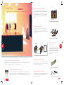
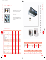
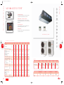
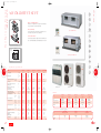
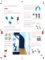
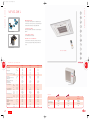
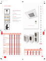
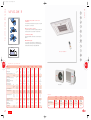
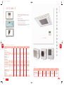
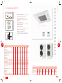
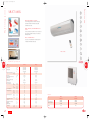
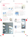
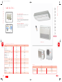
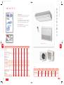
2/05/06
09:10
Página 2
Commercial range
056-057-06
Duct Inverter
Cassette Inverter
Fe a t u r e s a n d d e s i g n
i n p e r f e c t h a r m o ny
Wall Ceiling
O f f i c e s, c o m m e r c i a l p r e m i s e s, h o t e l s … w h a t ev -
56
57
er the desired space Fujitsu places a wide range
of
a i r- c o n d i t i o n i n g
units
at
your
disposal.
U n i f y i n g t h e m o s t i n n ova t i ve f e a t u r e s a n d t h e
Floor/ceiling Inverter
m o s t e l e g a n t d e s i g n , t h e n ew c o m m e r c i a l r a n g e
f r o m F u j i t s u p r ov i d e s ex c e p t i o n a l p e r fo r m a n c e
a n d q u a l i t y.
Large Ceiling Inverter
Window
index
2/05/06
09:12
Página 2
Duct Type.
Optimum performance guaranteed
Regulation of static pressure
Thanks to its static pressure adjustment function, normal-average or lower static pressure can be chosen during installation,
via the selector that is on the electrical panel.
1. Low static pressure level, mode 1 to 70 Pa (fan speed: high).
2. Medium static pressure level, air flow at 100 Pa (fan speed:
Air volume (m3/h.)
Commercial range technology
058-059-06
high).
Static pressure (PA)
Ultra compact units
These low-pr ofile models (21.7 cm in models of up to
5,400 W and 27 cm in models of up to 14,000 W) ar e also
extr emely compact as the junction box is built into the
side of the unit.
Conventional model
New model
58
1 Control
panel.
2 Fan cover.
3 Fan.
4 Motor.
M o r e c o n ve n i e n t
maintenance
To facilitate the maintenance of the units as
much as possible, the structure of the base
has been divided into two pieces (front and
rear). In addition, the position of the fan has
Lower panel: 2 units
Lower panel: 1 unit
D C i n ve r t e r, t h e s m a r t e s t t e ch n o l o g y
Outside electrical heater
The electr onics boar d of these units allows exter nal
Equipped with the DC inver ter advanced technology, the new Fujitsu models provide extraordinar y per formance
heater to be connected (optional) to operate in heating
and ensure large savings in energy with regard to conventional models.
mode while the defr osting takes place.
E ve r y t h i n g w i t h i n a r m ' s r e a ch
These models incorporate a new remote control with thermo sensor, which allows the tem-
Standard inlet and filters
perature to be read from the control in an accurate manner. The use of the remote sensor
The Fujitsu ducted models are equipped with standard return
makes it possible to control two areas of the house (day and night) with a single controller.
filters and a rectangular inlet (except high-pressure models).
The circular inlet is optional.
index
also been developed in 2 pieces (one higher
and one lower).
59
09:14
Página 60
D u c t Ty p e
2/05/06
D u c t Ty p e i n v e r t e r
060-061
AC Y 3 5 - 5 0 U i
Maximum installation versatility:
the Fujitsu direct impulsion models can be installed on either the floor
or the ceiling.
Remote control with thermo sensor:
this allows the temperature to be read from the remote control in a
Versatility of installation.
more accurate way.
Outside electrical heater:
the electronics board allows an external heater to be connected
(optional) to operate in heating mode while the defrosting takes place.
Remote control with thermo sensor.
Outside electrical heather (optional).
ACY35-50Ui
Te c h n i c a l s p e c i f i c a t i o n s
MODEL
60
Cooling capacity
Heating capacity
Energy efficiency ratio (E.E.R.)
ACY35Ui
ACY40Ui
ACY50Ui
kcal/h
3010
3612
4472 (1720-5074)
W
3500
4200
5200 (2000-5900)
kcal/h
3440
4128
5332 (1720-6450)
W
4000
4800
6200 (2000-7500)
Cooling
3,04
3,07
3,06
Heating
3,08
3,22
3,26
Power supply
Power consumption (Cooling/Heating)
V/nº/Hz
220/2/50
220/2/50
220/2/50
kW
1,15/1,30
1,37/1,49
1,70 / 1,90
Starting current
Running current (Cooling/Heating)
A
10
10
10
A
5,1/5,7
6,0/6,5
7,4 / 8,3
(O.U.) 2x2,5+T
(O.U.) 2x2,5+T
(O.U.) 2x2,5+T
3x1,5+T
3x1,5+T
3x1,5+T
Electrical wiring
Electrical connection
Air flow processed (max-min)
Static pressure (max-min)
Noise level indoor unit
(1)
Noise level outdoor unit
Dimensions indoor unit
Dimensions outdoor unit
Normal
m3/h
400/520
450/780
720/830
Low
m3/h
430/580
480/780
760/830
Normal
Pa
40/20
40/20
40/20
Low
Pa
20/0
20/0
20/0
High
dB (A)
34
40
38
Medium
dB (A)
31
36
34
Low
dB (A)
28
31
30
dB (A)
49
49
50
Code
Width
mm
953
953
953
Logistic reference indoor unit
Depth
mm
595
595
595
Logistic reference outdoor unit
Heigth
mm
217
217
217
Width
mm
830
830
830
Depth
mm
320
320
320
mm
650
650
650
Net weight (Indoor U./Outdoor U.)
Pipe size
Piping lenght max. (Total/Height)
Heigth
kg
25 / 54
25 / 54
25 / 54
1/4"-3/8"
1/4”-1/2”
1/4”-1/2”
m
25/15
25/15
25/15
Refrigerant
Refrigerant charge
type
R410A
R410A
R410A
Operating range
inch.
Cooling
Heating
(1) Static pressure 0 Pa
index
61
m
10
10
10
ºC
0 / +43
0 / +43
0 / +43
ºC
-15 / +24
-15 / +24
-15 / +24
ACY35-50Ui
Models
Price ref.
ACY35Ui
ACY40Ui
ACY50Ui
INVERTER HEAT PUMP
INVERTER HEAT PUMP
INVERTER HEAT PUMP
3NGF8520
3NGF8525
3NGF8530
ARY12L
ARY14L
ARY18LUAD
AOY12L
AOY14L
AOY18LMAKL
1.108
(Ask for availability)
1.200
(Ask for availability)
1.267
A c c e s s o r i e s (see details on page 204)
Code
Price ref.
SIMPLE WIRED
REMOTE CONTROLLER
REMOTE
SENSOR
EXTERIOR ELECTRICAL
HEATER
PUMP
CONDENSATE
3NGF...
4JAG0027
4JAG0024
4JBO0003
81
70
194
To consult
09:16
Página 62
D u c t Ty p e
2/05/06
D u c t Ty p e i n v e r t e r
062-063
AC Y 7 1 - 1 2 5 U i
HSensor
e a t i n temperatura
g sensor
Remote control with thermo sensor:
this allows the temperature to be read from the remote control in a
more accurate way.
Adjustment of static pressure:
either normal-medium static pressure or low static pressure may be
CMando
ontrol
chosen through the adjustment of the selector on the electronics
board.
Remote control with thermo sensor.
Outside electrical heater:
the electronics board allows an external heater to be connected
ACY71/80/100/125Ui
A i r v o l u m e ( m 3/ h )
(optional) to operate in heating mode while the defrosting takes place.
Static pressure (Pa)
1. Low static pressure level, mode 1 to 70 Pa
(fan speed: high).
2. Medium static pressure level, airflow at 100
Pa (fan speed: high).
Static pressure regulation function.
Te c h n i c a l s p e c i f i c a t i o n s
MODEL
62
ACY71Ui
Cooling capacity
Heating capacity
Energy efficiency ratio (E.E.R.)
ACY80Ui
ACY100Ui
ACY125Ui
kcal/h
6106 (1720-6880)
7310 (2580-8600)
8600 (4300-9632)
10750 (2580-12040)
W
7100 (2000-8000)
8500 (3000-10000)
10000 (5000-11200)
12500 (3000-14000)
kcal/h
6880 (1720-7310)
8600 (2580-9632)
9632 (4816-11352)
12040 (2580-13760)
W
8000 (2000-8500)
10000 (3000-11200)
11200 (5600-13200)
14000 (3000-16000)
Cooling
2,75
2,7
2,63
2,98
Heating
3,29
3,6
3,61
3,33
Power supply
Power consumption (Cooling/Heating)
V/nº/Hz
220/2/50
220/2/50
220/2/50
220/2/50
kW
2,58/2,43
3,15,/2,75
3,95/3,10
4,20/4,20
Starting current
A
10
10
10
15
Running current (Cooling/Heating)
Electrical wiring
Electrical connection
Air flow processed (min-max)
A
11,10/10,60
13,50/12,10
17,50/13,50
18,30/18,30
(O.U.) 2x4+T
(O.U.) 2x4+T
(O.U.) 2x4+T
(O.U.) 2x4+T
3x1,5+T
3x1,5+T
3x1,5+T
3x1,5+T
Static pressure (min-max)
Noise level indoor unit
(1)
Dimensions outdoor unit
670/1440
1120/2200
1120/2200
1120/2290
m3/h
950/1280
1580/2020
1580/2020
1680/2140
Normal
Pa
150/30
150/30
150/30
150/30
Low
Pa
100/30
100/30
100/30
100/30
High
dB (A)
35
43
43
44
Medium
dB (A)
32
41
41
42
dB (A)
30
39
39
40
dB (A)
52
53
53
54
Code
3NGF8535
3NGF8540
3NGF8545
3NGF8555
mm
1135
1135
1135
1135
Logistic reference indoor unit
ARY24LUAN
ARY30LUAN
ARY36LUAN
ARY45LUAN
Depth
mm
700
700
700
700
Logistic reference outdoor unit
AOY24LMAKL
AOY30LMAWL
AOY36LMAWL
AOY45LJBYLL
Heigth
mm
270
270
270
270
Width
mm
830
900
900
900
1.800
2.048
2.285
2.561
Depth
mm
320
330
330
330
SIMPLE WIRED
REMOTE CONTROLLER
REMOTE
SENSOR
EXTERIOR ELECTRICAL
HEATER
PUMP
CONDENSATE
3NGF...
4JAG0027
4JAG0025
4JBO0003
81
70
221
To consult
Width
mm
650
830
830
1290
kg
45/54
45/70
45/70
45/98
3/8”-5/8”
3/8”-5/8”
3/8”-5/8”
3/8”-5/8”
m
25/15
50/20
50/20
70/30
Refrigerant
type
R410A
R410A
R410A
R410A
index
ACY125Ui
m3/h
Heigth
(1) Static pressure 30 Pa
ACY80/100Ui
Normal
Net weight (Indoor U./Outdoor U.)
Pipe size
Piping lenght max. (Total/Height)
Refrigerant charge
Operating range
ACY71Ui
Low
Low
Noise level outdoor unit
Dimensions indoor unit
(except
mod.ACY71Ui)
Inch.
m
10
20
20
20
Cooling
ºC
0 / +43
0 / +43
0 / +43
0 / +43
Heating
ºC
-15 / +24
-15 / +24
-15 / +24
-15 / +24
Models
Price ref.
ACY71Ui
ACY80Ui
ACY100Ui
ACY125Ui
INVERTER HEAT PUMP
INVERTER HEAT PUMP
INVERTER HEAT PUMP
INVERTER HEAT PUMP
A c c e s s o r i e s (see details on page 204)
Code
Price ref.
63
09:19
Página 64
D u c t Ty p e
2/05/06
D u c t Ty p e i n v e r t e r
(high pressure)
064-065
AC Y 1 2 5 H - 1 4 0 U i
500
1.050
Easy installation:
thanks to the small size of the interior unit and the use of lighter
400
materials.
Low noise level:
Easy installation.
the new compact design of the appliances allows the internal air pres500 mm
Plastic fan
ø225mm
sure to be uniformly distributed, considerably reducing the noise level.
Exchanger
Remote control with thermo sensor:
400 mm
this allows the temperature to be read from the remote control in a
more accurate way. The use of the remote sensor makes it possible to
control two areas of the house (day and night) with a single controller.
ACY125H/140Ui
(High pressure)
Casing (plastic)
Low sound level.
1. Controller with thermo sensor
2. Simplified controller
3. Remote Sensor
Remote control with thermo sensor.
Te c h n i c a l s p e c i f i c a t i o n s
MODEL
64
Cooling capacity
Heating capacity
Energy efficiency ratio (E.E.R.)
ACY125HUi
ACY140Ui
kcal/h
10750 (2580-12040)
12040 (5504-13330)
W
12500 (3000-14000)
14000 (6400-15500)
kcal/h
12040 (2580-13760)
13760 (5848-15480)
W
14000 (3000-16000)
16000 (6800-18000)
Cooling
2,98
2,55
Heating
3,68
3,33
Power supply
V/nº/Hz
220/2/50
220/2/50
Power consumption (Cooling/Heating)
Starting current
kW
4,20/3,80
5,50/4,70
A
15
15
A
18,3 / 16,6
24,2 / 20,0
(O.U.) 2x4+T
(O.U.) 2x4+T
Running current (Cooling/Heating)
Electrical wiring
Electrical connection
Air flow processed (min-max)
Static pressure (max-min)
Noise level indoor unit
(1)
2460/3500
2460/3500
Low
m3/h
–
–
Normal
Pa
250/100
250/100
Low
Pa
–
–
High
dB (A)
49
49
Medium
dB (A)
46
46
dB (A)
42
42
dB (A)
54
54
Code
3NGF8550
3NGF8560
mm
1050
1050
Logistic reference indoor unit
ARY45LUAK
ARY54LUAK
Depth
mm
500
500
Logistic reference outdoor unit
AOY45LJBYL
AOY54LJAYL
Heigth
mm
400
400
Width
mm
900
900
2.561
2.780
Depth
mm
330
330
Width
mm
1290
1290
Net weight (Indoor U./Outdoor U.)
Heigth
kg
50/98
50/98
Pipe size
inch.
3/8”-5/8”
3/8”-5/8”
Piping lenght max. (Total/Height)
Refrigerant
m
70/30
70/30
type
R410A
R410A
Refrigerant charge
Operating range
(1) Static pressure 100 Pa.
index
ACY125H/140Ui
m3/h
Low
Dimensions outdoor unit
3x1,5+T
Normal
Noise level outdoor unit
Dimensions indoor unit
3x1,5+T
65
m
20
20
Cooling
ºC
0 / +43
0 / +43
Heating
ºC
-15 / +24
-15 / +24
Modelos
Price ref.
ACY125HUi
ACY140Ui
INVERTER HEAT PUMP
INVERTER HEAT PUMP
A c c e s s o r i e s (see details on page 204)
Code
Price ref.
SIMPLE WIRED
REMOTE CONTROLLER
REMOTE
SENSOR
PUMP
CONDENSATE
3NGF...
4JAG0027
4JBO0003
81
70
To consult
09:21
Página 66
D u c t Ty p e
2/05/06
D u c t Ty p e c o o l i n g - h e a t p u m p
066-067
AC Y 2 5 - 5 0 U / F
Versatile installation:
this is ideal for a lounge/dining room or bedrooms and hotels, as it
can be discretely installed in ceilings and on floors.
Energy Save:
they are fitted with the Energy save function that allows the
Maximum discretion of floor installation.
(mod. ACY_U)
performance of the unit to be optimised and thus provide a
considerable energy saving.
Outside electrical heater:
the electronics board allows an external heater to be connected
(optional) to operate in heating mode while the defrosting takes place.
Example of ceiling installation.
ACY25/35/40/50U/F
Outside electrical heater.
Te c h n i c a l s p e c i f i c a t i o n s
MODEL
66
Cooling capacity
Heating capacity
Energy efficiency ratio (E.E.R.)
ACY25U
ACY35U
ACY50U
ACY35F
ACY40F
ACY50F
kcal/h
2322
3010
4644
3010
3612
4644
W
2700
3500
5400
3500
4200
5400
kcal/h
2666
3440
5160
——-
——-
——-
W
3100
4000
6000
——-
——-
——-
2,81
2,82
2,81
2,82
3,02
2,66
Cooling
Heating
Power supply
Power consumption (Cooling/Heating)
Starting current
Running current (Cooling/Heating)
Electrical wiring
Electrical connection
Air flow processed
Normal
Low
Static pressure available (max-min) Normal
3,23
3,3
3,21
—-
——
——
V/nº/Hz
220/2/50
220/2/50
220/2/50
220/2/50
220/2/50
220/2/50
kW
2,03/-
0,96/0,96
1,24/1,21
1,92/1,87
1,24/-
1,39/-
A
21
30
39
29
29
39
A
4,4/4,5
5,5/5,4
8,8/8,7
5,5 /-
6,3/-
9,0/-
(O.U.) 2x2,5+T
(O.U.) 2x2,5+T
(O.U.) 2x2,5+T
(O.U.) 2x2,5+T
(O.U.) 2x2,5+T
(O.U.) 2x2,5+T
6x1,5+T
6x1,5+T
3x1,5+T
3x1,5+T
3x1,5+T
3x1,5+T
m3/h
360/390
360/500
600/1000
360/500
520/630
600/1000
m3/h
400/450
400/450
600/810
400/500
560/640
600/810
67
ACY25/35/40U/F
ACY50U/F
Pa
40/20
40/20
70/0
40/20
40/20
70/0
Low
Pa
20/0
20/0
60/0
20/0
20/0
60/0
Noise level indoor unit
High
dB (A)
35
29
43
29
26
43
(Free departure)
Medium
dB (A)
33
28
40
28
25
40
Low
dB (A)
31
27
36
27
24
36
dB (A)
48
49
52
49
49
52
Code
3NGF5440
3NGF5460
3NGF5510
3NGF4990
3NGF5005
3NGF5020
Width
mm
663
953
953
953
953
953
Logistic reference indoor unit
ARY9UUAB
ARY12UUAD
ARY18UUAD
ARY12FUAD
ARY14FUAD
ARY18FUAD
Depth
mm
595
595
595
595
595
595
Logistic reference outdoor unit
AOY9USAJL
AOY12USAJL
AOY18UNDKL
AOY12FSAJ
AOY14FSDJ
AOY18FNDK
Height
mm
217
217
217
217
217
217
Width
mm
750
750
830
750
750
830
962
1.000
1.152
950
1.025
1.094
Depth
mm
250
250
320
250
250
320
Noise level outdoor unit
Dimensions indoor unit
Dimensions outdoor unit
mm
530
530
650
530
530
650
Net weight (Indoor U./Outdoor U.)
Pipe size
Height
kg
18/30
25/34
25/52
25/34
25/35
25/47
1/4”-3/8”
1/4”-3/8”
1/4”-5/8”
1/4”-3/8”
1/4”-1/2”
1/4”-5/8”
Piping lenght max. (Total/Height)
m
15/8
15/8
20/8
15/8
15/8
20/8
Refrigerant
Refrigerant charge
Operating range
type
R410A
R410A
R410A
R410A
R410A
R410A
index
Inch.
m
7,5
7,5
7,5
7,5
7,5
7,5
Cooling
ºC
0 / +43
0 / +43
0 / +43
0 / +43
0 / +43
0 / +43
Heating
ºC
-7 / +24
-7 / +24
-7 / +24
Models
Price ref.
ACY25U
ACY35U
ACY50U
ACY35F
ACY40F
ACY50F
HEAT PUMP
HEAT PUMP
HEAT PUMP
COOLING ONLY
COOLING ONLY
COOLING ONLY
A c c e s s o r i e s (see details on page 204)
Code
Price ref.
SIMPLE WIRED
REMOTE CONTROLER
REMOTE
SENSOR
EXTERIOR ELECTRICAL
35/40/50 HEATER
PUMP
CONDENSATE
3NGF...
4JAG0027
4JAG0024
4JBO0003
81
70
194
To consult
09:24
Página 68
D u c t Ty p e
2/05/06
D u c t Ty p e c o o l i n g - h e a t p u m p
068-069
AC Y 7 1 - 8 0 U / F
Conventional model
New model
1. Control
panel
2. Fan cover
3. Fan
4. Motor
Control zone function:
a single controller allows up to 16 units to be connected, requiring a
single instruction to operate all of them at the same time.
Lower panel: 2 units
Lower panel: 1 units
Easy maintenance:
Easy maintenance.
access to all components is very simple thanks to the division of the
(mod. ACY_U)
structure into several parts.
Maximum versatility:
the Fujitsu conduit units have several options that allow easy
installation. The air return can be vertical or horizontal and there
are two outlets (one on each side) allowing you to choose the best
option for installation.
Example of insertion and suspension from the ceiling
respectively.
ACY71/80U/F
Te c h n i c a l s p e c i f i c a t i o n s
MODEL
68
Cooling capacity
Heating capacity
Energy efficiency ratio (E.E.R.)
ACY71U
ACY80U
ACY71F
ACY80F
kcal/h
6020
7225
6063
7225
W
7000
8400
7050
8400
kcal/h
6622
8170
—-
—-
W
7700
9500
—-
—-
2,64
2,81
2,71
2,81
Cooling
3,3
3,61
—-
—-
Power supply
Power consumption (Cooling/Heating)
V/nº/Hz
230/1/50
230/1/50
230/1/50
230/1/50
kW
2,65/2,33
2,99/2,63
2,60/-
2,99/-
Starting current
Running current (Cooling/Heating)
A
60
70
60
70
Heating
Electrical wiring
Electrical connection
Air flow processed (min-max)
A
Normal
Low
Static pressure available (max-min) Normal
Low
11,8/10,5
14/12,4
11,5/-
14/-
(O.U.) 2x4+T
(O.U.) 2x4+T
(O.U.) 2x4+T
(O.U.) 2x4+T
3x1,5+T
3x1,5+T
3x1,5+T
3x1,5+T
m3/h
670/1440
850/1800
670/1440
850/1800
m3/h
950/1280
1240/1600
950/1280
1240/1800
Pa
150/30
150/30
150/30
150/30
Pa
100/30
100/30
100/30
100/30
69
ACY71U/F
ACY80U/F
Models
Noise level indoor unit
High
dB (A)
38
40
38
40
(Free departure)
Medium
dB (A)
36
38
36
38
dB (A)
34
36
34
36
dB (A)
53
53
53
53
Code
3NGF5535
3NGF5545
3NGF5035
3NGF5045
mm
1135
1135
1135
1135
Logistic reference indoor unit
ARY25UUAN
ARY30UUAN
ARY25FUAN
ARY30FUAN
Depth
mm
700
700
700
700
Logistic reference outdoor unit
AOY25UNAKL
AOY30UNBWL
AOY25FNAKL
AOY30FNBWL
Height
mm
270
270
270
270
Width
mm
830
900
830
900
1.637
1.857
1.555
1.764
Depth
mm
320
330
320
330
SIMPLE WIRED
REMOTE CONTROLLER
REMOTE
SENSOR
EXTERIOR ELECTRICAL
HEATER
PUMP
CONDENSATE
3NGF...
4JAG0027
4JAG0025
4JBO0003
81
70
221
To consult
Low
Noise level outdoor unit
Dimensions indoor unit
Dimensions outdoor unit
Width
mm
650
830
650
830
Net weight (Indoor U./Outdoor U.)
Pipe size
Piping lenght max. (Total/Height)
kg
43/59
43/69
43/58
43/68
3/8”-5/8”
3/8”-5/8”
3/8”-5/8”
3/8”-5/8”
m
25/15
30/15
25/15
30/15
Refrigerant
Refrigerant charge
type
R410A
R410A
R410A
R410A
Height
Operating range
index
Inch.
m
7,5
7,5
7,5
7,5
Cooling
ºC
0 / +43
0 / +43
0 / +43
0 / +43
Heating
ºC
-7 / +24
-7 / +24
Price ref.
ACY71U
ACY80U
ACY71F
ACY80F
HEAT PUMP
HEAT PUMP
COOLING ONLY
COOLING ONLY
A c c e s s o r i e s (see details on page 204)
Code
Price ref.
09:25
Página 70
D u c t Ty p e
2/05/06
D u c t Ty p e c o o l i n g - h e a t p u m p
070-071
AC Y 1 0 0 - 1 2 5 T / U / U T / F T
Compact design:
these low-profile models (height 27 cm) are also extremely compact
as the junction box is incorporated into the side of the unit.
Adjustment of static pressure:
Compact design.
either normal-medium static pressure or low static pressure may be
(mod. ACY_T/U/UT)
chosen through the adjustment of the selector on the electronics board
(R410A models).
Air volume (m3/h)
Self diagnostics:
the remote controller allows you to check the self diagnostics of the
apparatus, making any possible error easy to find.
Ventilation:
it is possible to incorporate an outside air intake for ventilation as well
Static pressure (Pa)
ACY100T
as a horizontal or vertical return.
ACY100/125T/U/UT/FT
Adjustment of static pressure (R410A models).
ACY100/125T/U/UT/FT
Te c h n i c a l s p e c i f i c a t i o n s
MODEL
70
ACY100T
Cooling capacity
Heating capacity
Energy efficiency ratio (E.E.R.)
ACY100U
ACY100UT
ACY125UT
ACY100FT
ACY125FT
kcal/h
8944
9030
9030
10922
9030
10922
W
10400
10500
10500
12700
10500
12700
kcal/h
9116
10922
10922
12300
—-
—-
W
10600
12700
12700
14300
—-
—-
2,42
2,92
2,96
2,9
2,81
2,9
Cooling
3,07
3,48
3,48
3,25
—-
—-
Power supply
Power consumption (Cooling/Heating)
V/nº/Hz
230/1/50
230/1/50
400/3/50
400/3/50
400/3/50
400/3/50
kW
4,30/3,45
3,60/3,65
3,55/3,65
4,38/4,40
3,74/-
4,38/-
Starting current
A
105
*
37
67
37
67
Running current (Cooling/Heating)
Electrical wiring
Electrical connection
Air flow processed (min-max)
A
20,5/16,5
16/16,5
6/6,2
7,6/7,5
6,3/-
7,6/-
(O.U.) 2x6+T
(O.U.) 2x6+T
(O.U.) 3x2,5+N+T
(O.U.) 3x2,5+N+T
(O.U.) 3x2,5+N+T
(O.U.) 3x2,5+N+T
3x1,5+T
3x1,5+T
3x1,5+T
3x1,5+T
3x1,5+T
3x1,5+T
Heating
Normal
m3/h
1600/2000
1120/2200
1120/2200
1120/2290
1120/2200
1120/2290
Low
m3/h
-
1580/2020
1580/2020
1680/2140
1580/2020
1680/2140
Static pressure available (max-min) Normal
71
ACY100T
ACY100/125U/UT/FT
Pa
160/30
150/30
150/30
150/30
150/30
150/30
Low
Pa
-
100/30
100/30
100/30
100/30
100/30
Noise level indoor unit
High
dB (A)
47
43
43
44
43
44
(Free departure)
Medium
dB (A)
45
41
41
42
41
42
Low
dB (A)
43
39
39
40
39
40
56
54
54
54
54
54
Code
3NGF5660
3NGF5665
3NGF5565
3NGF5585
3NGF5065
3NGF5085
Width
mm
1210
1135
1135
1135
1135
1135
Logistic reference indoor unit
ARY36TLAA
ARY36UUAN
ARY36UUAN
ARY45UUAN
ARY36FUAN
ARY45FUAN
Depth
mm
700
700
700
700
700
700
Logistic reference outdoor unit
AOY36TPAFL
AOY36UMAXL
AOY36UNAXT
AOY45UMAXT
AOY36FNAXT
AOY45FMAXT
Height
mm
270
270
270
270
270
270
Width
mm
940
900
900
900
900
900
2.076
2.342
1.972
2.225
mm
370
330
330
330
330
330
2.076
(Ask for availability)
2.076
Depth
Noise level outdoor unit
Dimensions indoor unit
Dimensions exterior unit
dB (A)
mm
1152
1165
1165
1165
1165
1165
Net weight (Indoor U./Outdoor U.)
Pipe size
Piping lenght max. (Total/Height)
Height
kg
45/100
43/80
43/94
45/113
43/80
45/109
3/8”-3/4”
3/8”-5/8”
3/8”-5/8”
3/8”-3/4”
3/8”-5/8”
3/8”-3/4”
m
50/30
50/30
50/30
50/30
50/30
50/30
Refrigerant
type
R407C
R410A
R410A
R410A
R410A
R410A
Refrigerant charge
Operating range
Inch.
m
20
20
20
20
20
20
Cooling
ºC
0 / +43
0 / +43
0 / +43
0 / +43
0 / +43
0 / +43
Heating
ºC
-12/ +21
-10 / +24
-10 / +24
-10 / +24
*Information unavailable at the publicatiion time of this catalogue
index
Models
Price ref.
ACY 100 T
ACY 100 U
ACY 100 UT
ACY 125 UT
ACY 100 FT
ACY 125 FT
HEAT PUMP
HEAT PUMP
HEAT PUMP
HEAT PUMP
COOLING ONLY
COOLING ONLY
A c c e s s o r i e s (see details on page 204)
Code
Price ref.
SIMPLE WIRED
REMORE CONTROLLER
REMOTE
SENSOR
EXTERIOR ELECTRICAL
HEATER
PUMP
CONDENSATE
3NGF...
4JAG0027
4JAG00025
4JBO0003
81
70
221
To consult
09:27
Página 72
D u c t Ty p e
2/05/06
D u c t Ty p e c o o l i n g - h e a t p u m p
(High pressure)
072-073
AC Y 1 7 0 - 2 5 0 T T / U T / AT / F T
Ease of maintenance:
maintenance of the appliances is very easy as checks can be made at
the top, bottom, right or left of the unit (ACY250).
Accessibility:
A C Y 2 5 0 T T / AT
the exterior unit can also be positioned in service lifts and access to
(mod. ACY_T/U/UT)
the compressor is easy via the front cover (ACY250).
ACY170/250TT/AT
Low sound level:
the new compact design of the appliances allows the internal air pressure to be uniformly distributed, considerably reducing the noise level.
Easy access and maintenance (ACY250).
500 mm
Exchanger
ACY170UT/FT
400 mm
Plastic fan
ø225mm
A C Y 1 7 0 U T / F T / AT
Casing (plastic)
Low sound level.
Te c h n i c a l s p e c i f i c a t i o n s
72
MODEL
Cooling capacity
Heating capacity
Energy efficiency ratio (E.E.R.)
ACY170UT
ACY250TT
ACY170AT
ACY170FT
ACY250AT
kcal/h
14190
21330
14620
14190
21330
W
16500
24800
17000
16500
24800
kcal/h
16770
24850
—
-
—
W
19500
28900
—
-
—
2,72
2,03
2,74
2,78
2,31
Cooling
Heating
3,54
2,37
—
-
—
Power supply
Power consumption (Cooling/Heating)
Starting current
V/nº/Hz
400/3/50
400/3/50
400/3/50
400/3/50
400/3/50
kW
6,06/5,54
12,2/12,2
6,2/-
5,93/-
11,0/-
A
70
94
79
70
94
Running current (Cooling/Heating)
A
10,2/9,8
19,5/19,5
10,1/-
10,2/-
18/-
(O.U.) 3x4+N+T
3x6+N+T
(O.U.) 3x4+N+T
(O.U.) 3x4+N+T
3x6+N+T
Electrical wiring
Electrical connection
Airflow processed (min-max)
Static pressure available (min-max)
Noise level indoor unit
High
Noise level outdoor unit
Dimensions indoor unit
Dimensions outdoor unit
3x1,5+T
(3x1,5+T)+3x2,5
3x1,5+T
3x1,5+T
(3x1,5+T)+3x2,5
2000/3500
4300/5000
2000/4000
3500/2000
4300/5000
100/250
100/300
80/300
100/250
100/300
dB (A)
49
—
49
49
—
Medium
dB (A)
45
49
45
45
49
Low
dB (A)
42
—
42
42
—
dB (A)
54
59
59
54
59
mm
1050
1550
1050
1050
1550
Depth
mm
500
700
500
500
700
Height
mm
400
450
400
400
450
Width
mm
900
1300
940
900
1300
Depth
mm
330
650
370
330
650
Width
Height
m3/h
Pa
mm
1290
1380
1355
1290
1.380
Net weight (Indoor U./Outdoor U.)
Pipe size
kg
50/118
85/245
50/116
50/114
85/243
3/8”-3/4”
1/2”-1 1/8”
3/8”-3/4”
3/8”-3/4”
1/2”-1 1/8”
Piping lenght max. (Total/Height)
m
50/30
50/30
50/30
50/30
50/30
Refrigerant
Refrigerant charge
Operating range
type
R410A
R407C
R407C
R410A
R407C
index
Inch.
m
30
30
20
20
30
Cooling
ºC
0 / +43
0 / +46
0 / +43
0 / +43
0 / +43
Heating
ºC
-10 / +24
-10 / +21
-
-
-
73
ACY250TT/AT
ACY170AT
ACY170UT/FT
Models
ACY170UT
ACY250TT
ACY170AT
ACY170FT
ACY250AT
HEAT PUMP
HEAT PUMP
COOLING ONLY
COOLING ONLY
COOLING ONLY
Code
3NGF5605
3NGF5595
3NGF5090
3NGF5105
3NGF5095
Logistic reference indoor unit
ARY60UUAK
ARY90TLC3
ARY60EUAK
ARY60FUAK
ARY90ELC3
Logistic reference outdoor unit
AOY60UMAYT
AOY90TDC3L
AOY60EPAGT
AOY60FMAYT
AOY90EPD3L
2.772
4.571
2.633
2.633
4.342
Price ref.
A c c e s s o r i e s (see details on page 204)
Code
Price ref.
SIMPLE WIRED
REMOTE CONTROLLER
REMOTE
SENSOR
PUMP
CONDENSATE
3NGF...
4JAG0027
4JBO0003
81
70
To consult
09:30
Página 74
Cooling-heat pump models
2/05/06
Static pressure/Fan curve (I)
25
45
30
ACY 25 U
25
20
Static pressure (Pa)
Low
Low
15
10
15
400
500
600
700
800
900
0
320
1000
360
380
400
Air flow (m3/h)
Air flow (m3/h)
Normal mode
Normal mode
160
High
100
Medium
Static pressure (Pa)
100
80
Medium
20
60
ACY 35 U/F
60
15
10
Medium
Low
30
25
20
10
5
900
1100
1300
1500
500
600
700
800
900
1000
1100
1200
1300
1400
1500
380
430
120
High
Medium
Medium
100
120
Static pressure (Pa)
80
60
ACY 40 F
60
40
Low
Medium
Low
35
30
15
10
25
20
15
40
10
5
20
20
75
High
40
Medium
20
80
100
520
45
High
Low
Low
470
High mode
25
High
Static pressure (Pa)
140
420
Air flow (m3/h)
Normal mode
Low mode
160
370
Air flow (m3/h)
Air flow (m3/h)
Normal mode
0
320
480
Static pressure (Pa)
700
0
330
0
Air flow (m3/h)
Static pressure (Pa)
High
5
500
5
0
1,000
1,500
2,000
2,500
Air flow (m3/h)
0
1,000
1,500
2,000
0
400
2,500
450
500
Air flow (m3/h)
Normal mode
600
0
400
650
450
500
Air flow (m /h)
Low mode
650
Air flow (m /h)
45
High
70
Low
600
High mode
80
Medium
550
3
Normal mode
High
250
550
3
300
High
40
Medium
Medium
Low
35
Low
60
150
100
50
30
Static pressure (Pa)
ACY 50 U/F
Static pressure (Pa)
200
Static pressure (Pa)
420
15
20
0
50
40
2,500
3,000
3,500
4,000
20
15
20
10
5
0
2,000
25
30
10
index
400
35
Low
40
1,500
380
40
40
20
360
45
Medium
80
340
High mode
High
Low
Low
320
Air flow (m3/h)
High
Static pressure (Pa)
120
300
420
25
120
140
Static pressure (Pa)
0
340
Static pressure (Pa)
300
ACY 125 H / 140 UI
20
5
0
ACY 80/100 UI
25
10
5
5
74
Low
30
15
10
ACY 71 UI
Medium
35
Static pressure (Pa)
35
20
High
40
Medium
Medium
ACY 50 UI
45
High
High
40
Static pressure (Pa)
Inverter heat pump models
074-077
0
400
500
600
700
800
Air flow (m3/h)
Air flow (m /h)
Normal mode
Normal mode
3
900
1000
1100
0
550
600
650
700
750
Air flow (m /h)
3
High mode
800
850
09:30
Página 76
Static pressure/Fan curve (II)
120
160
160
Medium
Low
Static pressure (Pa)
ACY 71 U/F
140
Medium
100
Low
120
High
100
80
60
80
ACY 125 U/F
60
100
80
1000
0
500
1500
1,000
0
1000
1,500
2500
2000
2500
300
100
High
Medium
Low
250
Medium
Low
Static pressure (Pa)
80
60
80
ACY 170 U/F
60
Static pressure (Pa)
Low
100
40
200
150
100
40
20
20
0
500
1000
1500
0
500
2000
50
1000
1500
2000
0
1,500
Air flow (m3/h)
2,000
Air flow (m3/h)
Normal mode
2,500
3,000
3,500
4,000
Air flow (m3/h)
High mode
160
Normal mode
77
160
High
High
140
Medium
Low
120
Low
120
Static pressure (Pa)
100
80
60
300
Medium
250
ACY 170 TT
100
80
60
Static pressure (Pa)
140
HIGH
200
150
LOW
100
40
40
20
20
0
1000
1500
2000
2500
Air flow (m /h)
0
1000
50
0
1500
2000
2000
2500
3000
3
Normal mode
4000
Air flow (m3/h)
Air flow (m /h)
3
Normal mode
Low mode
300
200
415 V
180
160
250
ACY 250 AT/TT
HIGH
120
100
LOW
80
Static pressure (Pa)
140
Static pressure (Pa)
1500
Low mode
High
Medium
0
1000
Air flow (m3/h)
Normal mode
120
120
2000
Air flow (m3/h)
High
140
Static pressure (Pa)
1500
High mode
160
200
60
150
40
20
380 V
0
800
index
60
20
Air flow (m3/h)
Normal mode
ACY 100 TT
80
40
20
Air flow (m3/h)
ACY 100 U/F
Low
20
0
500
Static pressure (Pa)
Low
40
20
76
Medium
100
60
40
40
ACY 80 U/F
High
Medium
120
Static pressure (Pa)
140
120
High
Static pressure (Pa)
High
Cooling-heat pump models
2/05/06
Static pressure (Pa)
Cooling-heat pump models
074-077
1000
1200
1400
1600
1800
2000
2200
2400
2600
100
3000
3500
4000
Air flow (m3/h)
Air flow (m3/h)
Normal mode
Normal mode
4500
5000
2/05/06
09:32
Página 2
Cassette. Maximum flexibility
Air flow direction and auto swing
The unit can make a sweep using its deflector slats to air-condition
the premises more quickly. The direction of the sweep as well as the
auto swing function can be selected by using the remote control.
Maximum 5 m.
Commercial range technology
078-079-06
Efficient distribution of air
In order to be able to adapt to the shape of the room to be conditioned, the Fujitsu cassette units are
able to configure the air impulsion in two, three or four dif ferent directions and thus achieve uniform air
conditioning.
Convenient access and
easy maintenance
The control panel is easily accessible for maintenance tasks. There are also long-lasting filters
which can be easily dismantled for cleaning.
3 Directions
We e k l y p r o g r a m m i n g c o n t r o l
2 Directions
Water lifter
A series of water lifters are
included (up to 800 mm)
to discharge the condensation
water
4 Directions
Models with a movable r osette incorporate weekly pr ogramming conMon
Tues
Weds
Thurs
Fri
Sat
Sun
tr ol that allows on and of f pr ogramming up to twice a day. Functions:
- Pr ogramming of dif fer ent operating schedules each day.
Monday-Friday
Saturday
- On and of f pr ogramming twice a day.
Afternoon
- Set the time in periods of five minutes.
- Cancellation of operation on a specific day (public holiday).
Morning
T h e ve r s a t i l i t y o f t h e m ova b l e r o s e t t e
Morning
Thanks to the movable rosette, the machines can be adapted to a false ceiling with a lower height. All cassettes over 7,000 W can be installed in a standard position or in an ultra-small position, saving up to 3.5
Au t o m a t i c c l o s i n g o f t h e s l a t s
Standard position
Standard position
The slats open and close automatically when the unit is
285
235
tur ned on and of f r espectively. This leaves the apparatus
AUY 71-80
AUY 71 Ui
with a flat appearance and
Reduced height position
250
Reduced height position
200
78
cm of false ceiling height.
AUY 100-125-140
AUY 80-100-125-140 Ui
Controller with thermo sensor
These models incorporate a new remote control
with thermo sensor, which allows the temperature to be read from the controller in an accurate manner.
index
pr events dust getting inside.
Condition an adjacent room
An adjacent room can be conditioned using the cassette
units by connecting one or two flexible conduits with a
length of five metres.
79
09:35
Página 80
Cassette inverter
2/05/06
Cassette inverter
080-081
AU Y 3 5 - 5 0 U i
Minimum height:
they only require a false ceiling of 25 cm for installation. They are
ideal for offices, rooms or shops. The rosette coincides with the standard measurements of the European panel (650x650 mm).
Condensate pump:
standard pump that allows condensate water to be discharged up to
400 mm.
Possibility of air redistribution.
Long-lasting filters:
can be dismantled for easier cleaning.
External air contribution:
outside fresh air can be introduced by connecting a conduit to the
unit. This is especially useful in public premises that hold a lot of
people.
Easy access and maintenance.
AUY35/40/50Ui
80
Te c h n i c a l s p e c i f i c a t i o n s
MODEL
AUY35Ui
AUY40Ui
AUY50Ui
kcal/h
3010
3440
4042
W
3500
4000
4700
kcal/h
3440
3956
4128
W
4000
4600
4800
Cooling
3,02
2,96
2,85
Heating
2,92
2,82
2,81
V/nº/Hz
230/1/50
230/1/50
230/1/50
Power consumption (Cooling/Heating)
kW
1,16/1,37
1,36/1,63
1,65/1,71
Starting current
A
10
10
10
Running current (Cooling/Heating)
A
5,10/6,0
6,0/7,1
7,2/7,5
(O.U.) 2x2,5+T
(O.U.) 2x2,5+T
(O.U.) 2x2,5+T
3x1,5+T
3x1,5+T
3x1,5+T
Cooling capacity
Heating capacity
Energy efficiency ratio (E.E.R.)
Power supply
Electrical wiring
Electrical connection
Noise level indoor unit
High
dB (A)
42
42
44
Medium
dB (A)
39
39
41
dB (A)
36
36
37
dB (A)
49
49
50
580 (650)
580 (650)
580 (650)
Low
Noise level outdoor unit
Dimensions indoor unit
Dimensions outdoor unit
Width
mm
Depth
mm
580 (650)
580 (650)
580 (650)
Height
mm
235 (35)/250
235 (35)/250
235 (35)/250
Width
mm
830
830
830
Depth
mm
320
320
320
81
AUY35/40/50Ui
Models
mm
650
650
650
AUY35Ui
AUY40Ui
AUY50Ui
Net weight (Indoor U./Outdoor U.)
kg
18+2,2 / 54
18+2,2 / 54
18+2,2 / 54
INVERTER HEAT PUMP
INVERTER HEAT PUMP
INVERTER HEAT PUMP
Pipe size
Inch.
1/4”-3/8”
1/4”-1/2”
1/4”-1/2”
Piping lenght max. (Total/Height)
m
25/15
25/15
25/15
Refrigerant
Refrigerant charge
Operating range
type
R410A
R410A
R410A
10
10
10
Height
index
m
Cooling
ºC
0 / +43
0 / +43
0 / +43
Heating
ºC
-15 / +24
-15 / +24
-15 / +24
Code
3NGF8420
3NGF8425
3NGF8430
Logistic reference indoor unit
AUY12L
AUY14L
AUY18LBAB
Logistic reference outdoor unit
AOY12L
AOY14L
AOY18LMAKL
Price ref.
1.225
1.530
1.647
09:37
Página 82
Cassette Inverter
2/05/06
Cassette inverter
082-083
AU Y 7 1 - 1 4 0 U i
Remote control with thermo sensor:
this allows the temperature to be read from the remote control in a
more accurate way.
Condensate pump:
Remote controller with temperature sensor (thermo sensor).
standard pump that allows condensate water to be discharged up to
800 mm.
Standard position
Reduced height:
285
235
Standard position
the Fujitsu cassette units with a movable rosette can be installed in a
false ceiling with a reduced height of up to 200 mm.
Reduced height position
Energy save function:
200
250
Reduced height position
this optimises the unit's performance by adjusting the thermostat 1°C
AUY71Ui
AUY80-100-125-140Ui
every 60 minutes with the entailing energy saving.
Reduced high units.
Air
Exits
Air
Exterior
AUY71/80/100/125/140Ui
Air
Exits
External fresh air contribution.
82
Te c h n i c a l s p e c i f i c a t i o n s
MODEL
AUY71Ui
Cooling capacity
Heating capacity
AUY80Ui
AUY100Ui
AUY125Ui
AUY140Ui
11438 (5504-12470)
kcal/h
6106 (1720-6880)
7310 (2580-8600)
8600 (4300-9632)
10750 (2580-12040)
W
7100 (2000-8000)
8500 (3000-10000)
10000 (5000-11200)
12500 (3000-14000)
13300 (6400-14500)
kcal/h
6708 (1720-7740)
8600 (2580-9632)
9632 (4816-11352)
12040 (2580-13760)
13760 (5848-14190)
W
7800 (2000-9000)
10000 (3000-11200)
11200 (5600-13200)
14000 (3000-16000)
16000 (6800-16500)
Cooling
2,81
2,70
2,41
2,81
2,44
Heating
3,25
3,64
3,61
3,54
3,23
V/nº/Hz
230/1/50
230/1/50
230/1/50
230/1/50
230/1/50
Power consumption (Cooling/Heating)
kW
2,53/2,40
3,15/2,75
4,15/3,10
4,45/3,95
5,45/4,95
Starting current
Running current (Cooling/Heating)
Electrical wiring
Electrical connection
Noise level indoor unit
A
10
10
10
15
15
Energy efficiency ratio (E.E.R.)
Power supply
A
Dimensions outdoor unit
13,5/12,1
17,5/13,5
19,5/17,3
23,8/21,6
(O.U.) 2x4+T
(O.U.) 2x4+T
(O.U.) 2x4+T
(O.U.) 2x4+T
3x1,5+T
3x1,5+T
3x1,5+T
3x1,5+T
3x1,5+T
High
dB (A)
46
48
48
49
51
Medium
dB (A)
44
44
44
47
49
dB (A)
39
41
41
43
46
dB (A)
50
53
53
54
54
830 (940)
830 (940)
830 (940)
830 (940)
830 (940)
Low
Noise level outdoor unit
Dimensions indoor unit
11,1/10,5
(O.U.) 2x4+T
Width
mm
Depth
mm
830 (940)
830 (940)
830 (940)
830 (940)
830 (940)
Height
mm
246 (30)/200
296 (30)/250
296 (30)/250
296 (30)/250
296 (30)/250
Width
mm
830
900
900
900
900
Depth
mm
320
330
330
330
330
Height
83
(except mod. AUY71ui)
AUY71Ui
AUY80/100Ui
AUY125/140Ui
Models
mm
650
830
830
1290
1290
AUY71Ui
AUY80Ui
AUY100Ui
AUY125Ui
AUY140Ui
Net weight (Indoor U./Outdoor U.)
Pipe size
Piping lenght max. (Total/Height)
Refrigerant
kg
34/54
34/70
34/70
40/105
40/105
INVERTER HEAT PUMP
INVERTER HEAT PUMP
INVERTER HEAT PUMP
INVERTER HEAT PUMP
INVERTER HEAT PUMP
3/8”-5/8”
3/8”-5/8”
3/8”-5/8”
3/8”-5/8”
3/8”-5/8”
25/15
50/30
50/30
70/30
70/30
3NGF8455
Refrigerant charge
Operating range
m
index
Inch.
m
type
R410A
R410A
R410A
R410A
R410A
10
10
20
20
20
Cooling
ºC
0 / +43
-10/+43
-10/+43
-15/+43
-15/+43
Heating
ºC
-15 / +24
-15 / +24
-15/+24
-15/+24
-15/+24
Code
3NGF8435
3NGF8440
3NGF8445
3NGF8450
Logistic reference indoor unit
AUY24LUAR
AUY30LUAS
AUY36LUAS
AUY45LUAS
AUY54L
Logistic reference outdoor unit
AOY24LMAKL
AOY30LMAWL
AOY36LMAWL
AOY45LJBYL
AOY54L
1.886
2.076
2.457
2.686
3.331
Price ref.
09:38
Página 84
Cassette
2/05/06
Cassette cooling-heat pump
084-085
AU Y 3 5 - 5 0 U / F
Air impulsion system from 2 to 4
channels:
the air-conditioning can be adapted to the shape of the room by channelling the air in 2, 3 or 4 directions.
2 outlets.
Wireless remote control:
an ergonomic remote controller with a large display that allows the different features of the unit to be controlled in a functional mode.
3 outlets.
Condensate pump:
standard pump that allows condensate water to be discharged up to
400 mm.
Minimum height:
4 outlets.
they only require a false ceiling of 25 cm for installation. They are
(mod. AUY_U)
ideal for offices, rooms or shops. The rosette coincides with the stan-
Air impulsion system with 2, 3 or 4 outlets.
dard measurements of the European panel (650x650 mm).
58 cm
AUY35/40/50U/F
250 mm
20 mm
Minimum height.
84
Te c h n i c a l s p e c i f i c a t i o n s
MODEL
Cooling capacity
Heating capacity
Energy efficiency ratio (E.E.R.)
AUY35U
AUY40U
AUY50U
AUY35F
AUY40F
AUY50F
kcal/h
3053
3397
4171
3096
3526
4300
W
3550
3950
4850
3600
4100
5000
kcal/h
3440
3956
4644
—
—
—
W
4000
4600
5400
—
—
—
2,86
2,82
2,62
2,9
2,95
2,63
Cooling
Heating
3,31
3,24
2,7
—
—
—
Power supply
Power consumption (Cooling/Heating)
Starting current
V/nº/Hz
230/1/50
230/1/50
230/1/50
230/1/50
230/1/50
230/1/50
kW
1,24/1,21
1,40/1,42
1,85/2,00
1,24/-
1,39/-
1,90/-
A
30
31
39
30
31
39
Running current (Cooling/Heating)
Electrical wiring
Electrical connection
Noise level indoor unit
A
5,5/5,4
6,3/6,3
8,2/9,2
5,5/-
6,3/-
8,5/-
(O.U.) 2x2,5+T
(O.U.) 3x2,5+T
(O.U.) 3x2,5+T
(O.U.) 3x2,5+T
6x1,5+T
5x1,5+T
5x1,5+T
5x1,5+T
dB (A)
42
42
44
42
42
44
Medium
dB (A)
39
39
41
39
39
41
dB (A)
36
36
37
36
36
37
dB (A)
49
49
52
49
49
52
580(650)
580(650)
580(650)
580(650)
580(650)
580(650)
Low
Dimensions outdoor unit
(O.U.) 2x2,5+T
2X2,5+3x1,5+T
High
Noise level outdoor unit
Dimensions indoor unit
(O.U.) 2x2,5+T
2x2,5+3x1,5+T
Width
mm
Depth
mm
580(650)
580(650)
580(650)
580(650)
580(650)
580(650)
Height
mm
235(35)/250
235(35)/250
235(35)/250
235(35)/250
235(35)/250
235(35)/250
Width
mm
750
750
830
750
750
830
Depth
mm
250
250
320
250
250
320
85
AUY35/40U/F
AUY50U/F
Models
mm
530
530
650
530
530
650
AUY35U
AUY40U
AUY50U
AUY35F
AUY40F
AUY50F
Net weight (Indoor U./Outdoor U.)
kg
18+2,2/34
18+2,2/35
18+2,2/52
18+2,2/34
18+2,2/35
18+2,2/47
HEAT PUMP
HEAT PUMP
HEAT PUMP
COOLING ONLY
COOLING ONLY
COOLING ONLY
Pipe size
Piping lenght max. (Total/Height)
Inch.
1/4”-3/8”
1/4”-1/2”
1/4”-1/2”
1/4”-3/8”
1/4”-1/2”
1/4”-1/2”
m
20/8
20/8
20/8
20/8
20/8
20/8
Refrigerant
type
R410A
R410A
R410A
R410A
R410A
R410A
Refrigerant charge
m
7,5
7,5
7,5
7,5
7,5
7,5
Height
Operating range
index
Cooling
ºC
0 / +43
0 / +43
0 / +43
0 / +43
0 / +43
0 / +43
Heating
ºC
-7/ +24
-7/ +24
-7/ +24
-
-
-
Code
3NGF4645
3NGF4665
3NGF4520
3NGF4145
3NGF4165
3NGF4025
Logistic reference indoor unit
AUY12UBAB
AUY14UBAB
AUY18UBAB
AUY12FBAB
AUY14FBAB
AUY18FBAB
Logistic reference outdoor unit
AOY12USAJL
AOY14USDJL
AOY18UNCKL
AUOY12FSAJ
AOY14FSDJ
AOY18FNCKL
1.114
1.391
1.495
1.048
1.276
1.409
Price ref.
09:40
Página 86
Cassette
2/05/06
Cassette cooling-pump
086-087
AU Y 7 1 - 8 0 U / F
Remote control with thermo sensor:
this allows the temperature to be read from the remote control in a
more accurate way.
Reduced height:
Remote controller with temperature sensor (thermo sensor).
the cassette units with a movable rosette can be installed in a false
ceiling with a reduced height of up to 200 mm.
Comfort air-conditioning:
the automatic swing allows conditioned air to be correctly distributed,
providing a uniform temperature throughout the room.
Automatic swing function.
(mod. AUY_U)
Standard condensate pump (up to 800 mm of water
level difference).
AUY71/80U/F
86
Te c h n i c a l s p e c i f i c a t i o n s
AUY71U
AUY80U
AUY71F
AUY80A
AUY80F
kcal/h
6020
7225
6063
7310
7225
W
7000
8400
7050
8500
8400
kcal/h
6708
8170
—
—
—
W
7800
9500
—
—
—
2,64
2,85
2,71
2,38
2,85
MODEL
Cooling capacity
Heating capacity
Energy efficiency ratio (E.E.R.)
Cooling
3,32
3,42
—
—
—
V/nº/Hz
230/1/50
230/1/50
230/1/50
230/1/50
230/1/50
Power consumption (Cooling/Heating)
kW
2,65/2,35
2,95/2,78
2,60/-
3,53/-
2,95/-
Starting current
Running current (Cooling/Heating)
Electrical wiring
Electrical connection
Noise level indoor unit
A
60
70
60
90
70
A
11,8/10,5
13,6/13,1
11,5/-
16,9/-
13,8/-
(O.U.) 2x4+T
(O.U.) 22x4+T
(O.U.) 22x4+T
(O.U.) 22x4+T
(O.U.) 22x4+T
3x1,5+T
3x1,5+T
3x1,5+T
3x1,5+T
3x1,5+T
Heating
Power supply
High
dB (A)
44
46
44
46
46
Medium
dB (A)
42
44
42
44
44
dB (A)
38
41
39
41
41
dB (A)
53
53
53
54
53
830(940)
830(940)
830(940)
830(940)
830(940)
Low
Noise level outdoor unit
Dimensions indoor unit
Dimensions outdoor unit
Width
mm
Depth
mm
830(940)
830(940)
830(940)
830(940)
830(940)
Height
mm
246(30)/200
246(30)/200
246(30)/200
245(30)/200
246(30)/200
Width
mm
830
900
830
900
900
Depth
mm
320
330
320
350
330
87
AUY71U/F
AUY80U/F
AUY80A
Models
mm
650
830
650
900
830
AUY71U
AUY80U
AUY71F
AUY80A
AUY80F
Net weight (U.Indoor/U. Outdoor)
Pipe size
Piping lenght max. (Total/Height)
kg
34+6,5/59
34+6,5/69
34+6,5/58
34+6,5/77
34+6,5/68
HEAT PUMP
HEAT PUMP
COOLING ONLY
COOLING ONLY
COOLING ONLY
Inch.
3/8”-5/8”
3/8”-5/8”
3/8”-5/8”
3/8”-5/8”
3/8”-5/8”
m
25/15
30/15
25/15
30/15
30/15
Refrigerant
Refrigerant charge
type
R410A
R410A
R410A
R407C
R410A
7,5
7,5
7,5
7,5
7,5
Height
Operating range
index
m
Cooling
ºC
0 / +43
0 / +43
0 / +43
0 / +43
0 / +43
Heating
ºC
-7/ +24
-7/ +24
-
-
-
Code
3NGF4425
3NGF4445
3NGF4225
3NGF4240
3NGF4245
Logistic reference indoor unit
AUY25UUAR
AUY30UUAR
AUY25FUAR
AUY30ELBW
AUY30FUAR
Logistic reference outdoor unit
AOY25UNAKL
AOY30UNBWL
AOYFNAKT
AOY30EMBL
AOY30FNBWL
1.714
1.886
1.562
1.724
1.724
Price ref.
09:45
Página 88
Cassette
2/05/06
Cassette cooling-heat pump
088-089
AU Y 1 0 0 - 1 4 0 U T / F T
Mon
Tues
Weds
Thurs
Fri
Sat
Monday-Friday
Sun
Weekly programmer:
Saturday
this allows weekly operational programming, as well as pre-setting the
Afternoon
Morning
turning on and turning off of the unit up to twice a day.
Morning
Controller with thermo sensor:
Weekly programmer.
this allows the temperature to be read from the remote control in a
more accurate way.
285
Standard position
Condensate pump:
standard pump that allows condensate water to be discharged (up to
Reduced height position
250
800 mm of water level difference).
A U Y 1 0 0 / 1 2 5 / 1 4 0 U T / F T / AT
Easy maintenance:
the controller is easily accessible for maintenance tasks and the long-
AUY100-125-140
(mod. AUY_UT)
lasting filters can be easily dismantled for cleaning.
Reduced height installation.
External air contribution:
Air
Exits
outside fresh air can be introduced by connecting a conduit to the
Air
Exterior
unit. This is especially useful in public premises that hold a lot of
people.
AUY125AT
AUY100-140UT/FT
Air
Exits
External fresh air contribution.
88
89
Te c h n i c a l s p e c i f i c a t i o n s
MODEL
AUY100UT
Cooling capacity
Heating capacity
Energy efficiency ratio (E.E.R.)
AUY125UT
AUY140UT
AUY100FT
AUY125AT
AUY125FT
AUY140FT
kcal/h
9030
10922
12470
9030
10922
10922
12470
W
10500
12700
14500
10500
12700
12700
14500
kcal/h
10148
12298
14190
—-
—-
—-
—-
W
11800
14300
16500
—-
—-
—-
—-
3,02
2,9
2,81
2,84
2,65
2,90
2,81
Cooling
Heating
3,23
3,26
3,11
—-
—-
—-
—-
Power supply
Power consumption (Cooling/Heating)
Starting current
V/nº/Hz
400/3/50
400/3/50
400/3/50
400/3/50
400/3/50
400/3/50
400/3/50
kW
3,48/3,65
4,38/4,40
5,16/5,30
3,70/-
4,76/-
4,38/-
5,16/-
A
37
67
70
37
66
67
70
Running current (Cooling/Heating)
Electrical wiring
Electrical connection
Noise level indoor unit
A
5,9/6,2
7,7/7,7
9,5/9,5
6,2/-
8,6/-
7,7/-
9,5/-
(O.U.) 3x 2,5+N+T
(O.U.) 3x 2,5+N+T
(O.U.) 3x 2,5+N+T
(O.U.) 3x 2,5+N+T
(O.U.) 3x 2,5+N+T
(O.U.) 3x 2,5+N+T
(O.U.) 3x 2,5+N+T
3x1,5+T
3x1,5+T
3x1,5+T
3x1,5+T
3x1,5+T
3x1,5+T
3x1,5+T
High
dB (A)
48
49
52
48
49
49
52
Medium
dB (A)
44
47
48
44
47
47
48
Low
dB (A)
41
43
45
41
43
43
45
dB (A)
54
54
54
54
59
54
54
830 (940)
830 (940)
830 (940)
830 (940)
830 (940)
830 (940)
830 (940)
Noise level outdoor unit
Dimensions indoor uni
Dimensions outdoor unit
Width
mm
Depth
mm
830 (940)
830 (940)
830 (940)
830 (940)
830 (940)
830 (940)
830 (940)
Height
mm
296 (30)/250
296 (30)/250
296 (30)/250
296 (30)/250
296 (30)/250
296 (30)/250
296 (30)/250
Width
mm
900
900
900
900
940
900
900
Depth
mm
330
330
330
330
370
330
330
AUY125AT
AUY100/125/140FT/UT
Models
mm
1165
1165
1290
1165
1152
1165
1290
AUY100UT
AUY125UT
AUY140UT
AUY100FT
AUY125AT
AUY125FT
AUY140FT
Net weight (Indoor U./Outdoor U.)
kg
34+6,5/94
40+6,5/113
40+6,5/118
34+6,5/80
40+6,5/102
40+6,5/109
40+6,5/114
HEAT PUMP
HEAT PUMP
HEAT PUMP
HEAT PUMP
COOLING ONLY
COOLING ONLY
COOLING ONLY
Pipe size
Piping lenght max. (Total/Height)
Inch.
3/8”-5/8”
3/8”-3/4”
3/8”-3/4”
3/8”-5/8”
3/8”-3/4”
3/8”-3/4”
3/8”-3/4”
m
50/30
50/30
50/30
50/30
50/30
50/30
50/30
Refrigerant
type
R410A
R410A
R410A
R410A
R407C
R410A
R410A
Refrigerant charge
Operating range
m
20
20
20
20
20
20
20
Height
index
Cooling
ºC
0 / +43
0 / +43
0 / +43
0 / +43
0 / +43
0 / +43
0 / +43
Heating
ºC
-10/ +24
-10/ +24
-10/ +24
-
-
-
-
Code
3NGF4465
3NGF4485
3NGF4595
3NGF4265
3NGF4280
3NGF4285
3NGF4295
Logistic reference indoor unit
AUY36UUAS
AUY45UUAS
AUY54UUAS
AUY36FUAS
AUY45ELB3W
AUY45FUAS
AUY54FUAS
Logistic reference outdoor unit
AOY36UNAXT
AOY45UMAXT
AOY54UMAYT
AOY36FNAXT
AOY45EPA3L
AOY45FMAXT
AOY54FMAYT
2.238
2.438
2.810
2.010
2.219
2.219
2.572
Price ref.
Commercial range technology
090-091-06
2/05/06
09:47
Página 2
Wall ceiling. Better quality air
A design full of benefits
The Fujitsu wall ceiling units offer unbeatable aesthetics as the air
return located at the rear is hidden from view once the unit is
installed. This leaves these models with a flat front and an elegant
rounded shape. This air inlet layout improves comfor t by offering a
greater airflow and reducing noise.
Perfect for every room
Less friction, more
force of air
The upper location of the air inlet reduces
air friction.
This considerably increases the force of
the airflow and the distance reached (up to
Cool operation
Thermal operation
10 m).
C o n ve n i e n t m a i n t e n a n c e
Filters
The wall ceiling units offer simple extraction of the condensate
tray and easy access to the long-lasting filter s.
90
Condensate tray
Simpler installation
The Fujitsu wall ceiling units come with a template similar to the
wall models, making installation a lot easier. The outlet tubing also
offers greater flexibility as it can be installed on the left or the
right.
Heat exchanger
100% efficient
The DC motor of these models offers greater performance which
improves its efficiency ratio. Elsewhere, the lambda-shape design of
the batter y provides a greater air exchange ser vice, achieving the
desired temperature in less time.
High efficiency
DC motor
index
91
09:48
Página 92
Wa l l C e i l i n g
2/05/06
Wa l l C e i l i n g i n v e r t e r
092-093
AW Y 7 1 - 8 0 U i
New flow impulsion system:
vertical in heating pump mode and horizontal in cooling mode,
generating a comfortable environment that avoids possible
uncomfortable direct currents.
Vertical flow exit in
heating mode.
High efficiency and minimum noise
level:
the entry of air through the top allows the noise level to be reduced
and increases the air impulsion current (up to 10 m), leading to
Horizontal flow exit in
cooling mode.
maximum performance.
Comfortable air flow.
Ease of maintenance:
easy access to the long-lasting filters for cleaning purposes and
an extractable and washable condensate tray.
High efficiency and minimum noise level.
AW Y 7 1 / 8 0 U i
Elegant and exclusive design.
92
Te c h n i c a l s p e c i f i c a t i o n s
MODEL
AWY71Ui
AWY80Ui
kcal/h
5848 (1720-6880)
6880 (1720-7396)
W
6800 (2000-8000)
8000 (2000-8600)
kcal/h
6020 (1720-7740)
7310 (1720-8600)
W
7000 (2000-9000)
8500 (2000-10000)
Cooling
3,21
2,63
Heating
3,61
3,02
V/nº/Hz
230/1/50
230/1/50
kW
2,12/1,94
3,04/2,81
Cooling capacity
Heating capacity
Energy efficiency ratio (E.E.R.)
Power supply
Power consumption (Cooling/Heating)
Starting current
Running current (Cooling/Heating)
Electrical wiring
Electrical connection
Noise level indoor unit
Dimensions outdoor unit
10
10
A
9,3/8,5
13,3/12,3
(O.U.) 2x4+T
(O.U.) 2x4+T
2x2,5+1X1,5+T
2x2,5+1X1,5+T
High
dB (A)
47
47
Medium
dB (A)
43
43
Low
dB (A)
40
40
Superquiet
dB (A)
37
37
dB (A)
53
53
mm
1150
1150
Depth
mm
285
285
Height
mm
270
270
Width
mm
900
900
Depth
mm
350
350
Height
Noise level outdoor unit
Dimensions indoor unit
A
Width
93
AWY71/80Ui
Models
mm
900
900
AWY71Ui
AWY80Ui
Net weight (Indoor U./Outdoor U.)
kg
16/70
16/70
INVERTER HEAT PUMP
INVERTER HEAT PUMP
Pipe size
Inch.
3/8”-5/8”
3/8”-5/8”
Piping lenght max. (Total/Height)
m
25/15
25/15
Refrigerant
type
R410A
R410A
Refrigerant charge
m
10
10
Operating range
index
Cooling
ºC
0 / +43
0 / +43
Heating
ºC
-15/ +24
-15/ +24
Code
3NGF8075
3NGF8080
Logistic reference indoor unit
AWY24LBAJ
AWY30LBAJ
Logistic reference outdoor unit
AOY24LMAL
AOY30LMAL
1.353
2.219
Price ref.
09:50
Página 94
Wa l l C e i l i n g
2/05/06
Wa l l C e i l i n g h e a t p u m p
094-095
AW Y 4 0 - 8 0 U
Conventional slat
High performance and DC motor:
the lambda shape achieves a greater air exchange surface, reaching
New slat
that reduces turbulence
the desired temperature in less time.
Low noise level and maximum
discretion:
Silent fan
that reduces
the noise level
it exclusive and elegant design, featuring hidden grilles and air entry at
Low noise level.
the top, notably reduces the noise level of the air-conditioning unit. It
also has a luminous display showing the operation of the appliance.
Ease of maintenance:
Cooling / dehumidifying / fan
through the easy extraction of the condensate tray and accessibility to
the filter system.
Heating
Automatic vertical and horizontal fan:
Operating display indicator
the layout of the vertical and horizontal slats, as well as automatic
adjustment, allow the air impulsion angle to be modified, preventing
stratification and achieving optimum air-conditioning in a short space
of time.
AW Y 4 0 / 5 0 / 7 1 / 8 0 U
Maximum discretion and elegance.
94
95
Te c h n i c a l s p e c i f i c a t i o n s
AWY40U
AWY50U
AWY71U
AWY80U
kcal/h
3615
4645
5850
6795
W
4200
5400
6800
7900
kcal/h
3955
4905
6365
7225
W
4600
5700
7400
8400
Cooling
2,90
2,92
2,83
2,87
Heating
3,59
3,08
3,08
3,05
MODEL
Cooling capacity
Heating capacity
Energy efficiency ratio (E.E.R.)
Power supply
Power consumption (Cooling/Heating)
V/nº/Hz
230/1/50
230/1/50
230/1/50
230/1/50
kW
1,45/1,28
1,85/1,85
2,40/2,40
2,75/2,75
Starting current
A
31
39
60
70
Running current (Cooling/Heating)
A
6,5/5,7
8,3/8,3
10,6/10,5
13,0/13,0
Electrical wiring
Electrical connection
Noise level indoor unit
(O.U.) 2x4+T
(O.U.) 2x4+T
6x1,5+T
6x1,5+T
dB (A)
37
39
43
46
Medium
dB (A)
35
36
40
44
dB (A)
32
33
36
41
dB (A)
50
52
52
54
mm
1150
1150
1150
1150
Depth
mm
285
285
285
285
Height
mm
270
270
270
270
Width
mm
750
830
830
900
Depth
mm
250
320
320
350
Low
Dimensions outdoor unit
(O.U.) 2x2,5+T
2x2,5+3x1,5+T
High
Noise level outdoor unit
Dimensions indoor unit
(I.U.) 2x2,5+T
2x2,5+2x1,5+T
Width
AWY40U
AWY50/71U
AWY80U
Models
mm
530
650
650
900
AWY40U
AWY50U
AWY71U
AWY80U
Net weight (Indoor U./Outdoor U.)
kg
16/35
16/52
16/59
16/74
HEAT PUMP
HEAT PUMP
HEAT PUMP
HEAT PUMP
Pipe size
Piping lenght max. (Total/Height)
Inch.
1/4”-1/2”
1/4”-5/8”
3/8”-5/8”
3/8”-5/8”
m
15/8
20/8
20/8
25/15
Refrigerant
type
R410A
R410A
R410A
R410A
Refrigerant charge
Operating range
m
7,5
7,5
7,5
7,5
Height
index
Cooling
ºC
0 / +43
0 / +43
0 / +43
0 / +43
Heating
ºC
-7/ +24
-7/ +24
-7/ +24
-7/ +24
Code
3NGF2630
3NGF2640
3NGF2650
3NGF2660
Logistic reference indoor unit
AWY14UBBJ
AWY18UBBJ
AWY24UBBJ
AWY30UBBJ
Logistic reference outdoor unit
AOY14USBJ
AOY18UNBKL
AOY24UNBKL
AOY30UNBDL
828
962
1.152
1.962
Price ref.
Commercial range technology
096-097-06
2/05/06
09:51
Página 2
Ceiling units. Complete versatility
Floor-ceiling units. Free choice
Semi-insertable units
I n s t a l l a t i o n f l ex i b i l i t y
10 cm.
False ceiling
Using a false ceiling with a height of 15 cm, the ceiling units can
All the units can be positioned either on the floor or
be semi-inser ted to allow only 14 cm to be visible. In addition, the
the ceiling through the use of an L-shaped cover that
profile of the inside unit is designed to fit into a false ceiling
allows condensation water to be collected in any
made of plaster.
14 cm.
position. The fastening system is also designed to
fix the unit in both positions.
Full remote control
The functions of the Fujitsu ceiling units are controlled with
Selection of air outlet
an ergonomic and easy to use remote control.
The remote control allows the air outlet direction and the
• Air Flow Direction: Allows the air outlet direction to be
fan function to be chosen with horizontal or ver tical
chosen (up/down or left/right).
sweeps. Likewise, the double deflector slat system uni-
• Swing: The air is uniformly distributed around the room
formly distributes the airflow avoiding the unpleasant
using a sweep in all directions.
effects that direct airflow can cause.
Remote control
The filters, always within reach
Air filter
Because of the easy access their location offers, the fil-
96
ters can be changed without the need for an engineer.
Handle
And to avoid corrosion through humidity they are made
E a s y a n d c o n ve n i e n t
installation
Support
Base
with a polyethylene-based material.
97
Intake grille
There is a template that indicates the
distances and the position of the fastening making the interior unit easy to
install with the use of just four screws.
These units are fitted with front and
back handles at the same height and
on the left and right to facilitate transpor t and installation.
Installation example
A i r r e n ewa l
Outdoor air
Fresh air from outside can be introduced by connecting a conduit
at the top or rear par t of the unit. A ver y useful option in public
premises.
index
Indoor air
09:52
Página 98
Floor/ceiling
2/05/06
Floor/ceiling Inverter
098-099
ABY50-71Ui
Auto swing function:
the horizontal and vertical air sweep combination allows three-dimen655
sional control of the air direction.
Large flow twin slat:
990
(unit: mm)
the hot and cold air is rapidly and uniformly distributed throughout the
199
room thanks to a specially designed twin slat that allows a larger airflow to be generated.
Compact design.
Universal installation:
Right-left
sweep
1
3
2
Up-down
sweep
the same unit can be installed on the floor or in the ceiling as the Lshaped cover collects condensate in any position and the fastening
1
4
2
5
system allows it to be attached in both positions.
3
4
5 positions
4 positions
Twin automatic sweep (auto swing).
ABY50/71Ui
98
Te c h n i c a l s p e c i f i c a t i o n s
ABY50Ui
ABY71Ui
kcal/h
4472
5590
W
5200
6500
kcal/h
5332
5850
W
6200
6800
Cooling
3,06
3,02
Heating
3,26
3,42
V/nº/Hz
230/1/50
230/1/50
Power consumption (Cooling/Heating)
kW
1,70/1,90
2,15/1,99
Starting current
Running current (Cooling/Heating)
Electrical wiring
Electrical connection
Noise level indoor unit
A
10
10
A
7,4/8,3
9,4/8,7
(O.U.) 2x2,5+T
(O.U.) 2x4+T
3x1,5+T
3x1,5+T
MODEL
Cooling capacity
Heating capacity
Energy efficiency ratio (E.E.R.)
Power supply
Noise level outdoor unit
Dimensions indoor unit
Dimensions outdoor unit
High
dB (A)
44
50
Medium
dB (A)
40
46
Low
dB (A)
36
42
dB (A)
50
53
Width
mm
990
990
Depth
mm
655/199
655/199
Height
mm
199/655
199/655
Width
mm
830
900
Depth
mm
320
350
99
ABY50Ui
ABY71Ui
Models
mm
650
900
ABY50Ui
ABY71Ui
Net weight (Indoor U./Outdoor U.)
Pipe size
Piping lenght max. (Total/Height)
kg
28/54
28/70
IINVERTER HEAT PUMP
INVERTER HEAT PUMP
1/4”-1/2”
3/8”-5/8”
m
25/15
25/15
Refrigerant
Refrigerant charge
type
R410A
R410A
10
10
Height
Operating range
index
Inch.
m
Cooling
ºC
0 / +43
0 / +43
Heating
ºC
-15/ +24
-15/ +24
Code
3NGF8320
3NGF8330
Logistic reference indoor unit
ABY18LBAJ
ABY24LBAJ
Logistic reference outdoor unit
AOY18LMAKL
AOY24LMAL
1.057
1.353
Price ref.
09:54
Página 100
Floor/ceiling
2/05/06
Floor/ceiling cooling-heat pump
100-101
ABY40-71U/F
NMT function:
the Nice Morning Timer allows the unit is to calculate the start time in
order that the room is conditioned at the time set by the user.
Sleep function:
this adjusts the room temperature to the needs of the human body,
raising the programmed room temperature by up to 4ºC in winter and
by up to 2ºC in summer, providing a considerable energy saving.
Air flow direction:
this makes it possible to select the flow output direction and contribute to a more rapid and uniform distribution.
(mod. ABY_U)
Universal installation.
1°C 2°C 3°C 4ºC
Adjusted time
1 hour
1 hour
30
min.
1 hour
1°C
1 hour 30 min.
2°C
Adjusted time
Automatic winter adjustment
Automatic summer adjustment
Smart functions NMT (Nice Morning Timer) and Sleep.
100
ABY40/50/71U/F
Te c h n i c a l s p e c i f i c a t i o n s
MODEL
Cooling capacity
Heating capacity
Energy efficiency ratio (E.E.R.)
ABY40U
ABY50U
ABY71U
ABY40F
ABY50F
ABY71F
kcal/h
3440
4645
5590
3612
4645
5590
W
4000
5400
6500
4200
5400
6500
kcal/h
4045
5160
6365
—-
—-
—-
W
4700
6000
7400
—-
—-
—2,65
Cooling
2,82
2,84
2,69
3,02
2,81
Heating
3,48
3,24
3,22
—-
—-
—-
Power supply
V/nº/Hz
230/1/50
230/1/50
230/1/50
230/1/50
230/1/50
230/1/50
Power consumption (Cooling/Heating)
Starting current
Running current (Cooling/Heating)
kW
1,42/1,35
1,90/1,85
2,42/2,30
1,39/-
1,92/-
2,45/-
A
31
39
60
31
39
60
A
6,3/6,0
8,6/8,3
10,8/10,3
6,3/-
8,5/-
11,0/-
Electrical wiring
Electrical connection
Noise level indoor unit
Noise level outdoor unit
Dimensions indoor unit
Dimensions outdoor unit
(O.U.) 2x2,5+T
(O.U.) 2x2,5+T
(O.U.) 2x4+T
(O.U.) 2x2,5+T
(O.U.) 2x2,5+T
(O.U.) 2x4+T
2x2,5+2x1,5+T
2x2,5+3x1,5+T
2x4+3x1,5+T
3x1,5+T
3x1,5+T
3x1,5+T
High
dB (A)
41
46
48
41
46
48
Medium
dB (A)
38
42
44
38
42
44
Low
dB (A)
35
37
40
35
37
40
dB (A)
49
52
53
49
52
53
Width
mm
990
990
990
990
990
990
Depth
mm
655/199
655/199
655/199
655/199
655/199
655/199
Height
mm
199/655
199/655
199/655
199/655
199/655
199/655
Width
mm
750
830
830
750
830
830
Depth
mm
250
320
320
250
320
320
101
ABY40U/F
ABY50/71U/F
Models
mm
530
650
650
530
650
650
ABY40U
ABY50U
ABY71U
ABY40F
ABY50F
ABY71F
Net weight (Indoor U./Outdoor U.)
Pipe size
Piping lenght max. (Total/Height)
kg
28/35
28/52
28/59
28/35
28/47
28/58
HEAT PUMP
HEAT PUMP
HEAT PUMP
COOLING ONLY
COOLING ONLY
COOLING ONLY
1/4”-1/2”
1/4”-5/8”
3/8”-5/8”
1/4”-1/2”
1/4”-5/8”
3/8”-5/8”
m
15/8
20/8
20/8
15/8
20/8
20/8
Refrigerant
type
R410A
R410A
R410A
R410A
R410A
R410A
Refrigerant charge
m
7,5
7,5
7,5
7,5
7,5
7,5
Height
Operating range
index
Inch.
Cooling
ºC
0 / +43
0 / +43
0 / +43
+21/ +43
+21/ +43
+21/ +43
Heating
ºC
-8/ +24
-8/ +24
-8/ +24
-
-
-
Code
3NGF3195
3NGF3220
3NGF3230
3NGF2995
3NGF3020
3NGF3030
Logistic reference indoor unit
ABY14UBBJ
ABY18UBBJ
ABY24UBBJ
ABY14FBBJ
ABY18FBBJ
ABY24FBBJ
Logistic reference outdoor unit
AOY14USDJL
AOY18UNBKL
AOY24UNBKL
AOY14FSDJ
AOY18FNBK
AOY24FNBK
867
1.000
1.104
781
914
1.028
Price ref.
09:56
Página 102
Large ceiling
2/05/06
Large ceiling Inverter
102-103
ABY80-125Ui
Twin auto swing:
that allows 5 selections for the vertical or horizontal airflow direction.
Outside fresh air contribution:
via a conduit with a diameter of 200 mm connected to the upper or
Horizontal fan.
rear part of the machine. Air renewal is very useful in public premises
that hold a lot of people.
Optional drain water lifter:
an optional accessory that allows a level difference about 30 cm
in the false ceiling to be able to generate the necessary slope until it
reaches the nearest down pipe (see page 172).
Semi-insertable units:
Vertical fan.
these units are designed to fit into a plaster false ceiling with a minimum height of 15 cm. This means only 14 cm of the machine will be
visible.
Air
Exterior
ABY80/100/125Ui
Air
Interior
External fresh air contribution.
102
Te c h n i c a l s p e c i f i c a t i o n s
MODEL
ABY80Ui
Cooling capacity
Heating capacity
ABY100Ui
kcal/h
7310
8600
10750
W
8500
10000
12500
kcal/h
8600
9288
12040
W
10000
10800
14000
Cooling
2,83
2,43
2,81
Heating
3,45
3,31
3,29
V/nº/Hz
230/1/50
230/1/50
230/1/50
Power consumption (Cooling/Heating)
kW
3,0/2,90
4,12/3,26
4,45/4,25
Starting current
Running current (Cooling/Heating)
Electrical wiring
Electrical connection
Noise level indoor unit
A
10
10
15
A
13,1/12,7
18,0/14,2
19,5/18,5
(O.U.) 2x2,5+T
(O.U.) 2x4+T
(O.U.) 2x4+T
3x1,5+T
3x1,5+T
3x1,5+T
Energy efficiency ratio (E.E.R.)
Power supply
High
dB (A)
45
48
50
Medium
dB (A)
42
45
47
dB (A)
37
40
43
dB (A)
53
54
54
mm
1660
1660
1660
Depth
mm
700
700
700
Height
mm
240
240
240
Width
mm
900
900
900
Depth
mm
330
330
330
Low
Noise level outdoor unit
Dimensions indoor unit
Dimensions outdoor unit
Width
103
ABY125Ui
ABY80/100Ui
ABY125Ui
Models
mm
830
830
1290
ABY80Ui
ABY100Ui
ABY125Ui
Net weight (Indoor U./Outdoor U.)
Pipe size
Piping lenght max. (Total/Height)
kg
48/70
48/70
48/105
INVERTER HEAT PUMP
INVERTER HEAT PUMP
INVERTER HEAT PUMP
3/8”-5/8”
3/8”-5/8”
3/8”-5/8”
m
50/30
50/30
70/30
Refrigerant
Refrigerant charge
type
Height
Operating range
index
Inch.
R410A
R410A
R410A
m
10
20
20
Cooling
ºC
-10/ +43
-10/ +43
-15/ +43
Heating
ºC
-15/+24
-15/+24
-15/+24
Code
3NGF8340
3NGF8350
3NGF8360
Logistic reference indoor unit
ABY30LBAG
ABY36LBAG
ABY45LBAG
Logistic reference outdoor unit
AOY30LMAWL
AOY36LMAWL
AOY45LJBYL
2.255
2.486
2.914
Price ref.
09:57
Página 104
Large ceiling
2/05/06
Large ceiling cooling- heat pump
104-105
ABY80-140U/UT/F/FT
Large air current:
ideal for large commercial premises, warehouses and offices with a
height of up to 4 m.
Horizontal fan
Outside fresh air contribution:
via a conduit with a diameter of 200 mm connected to the upper or
rear part of the machine. Air renewal is very useful in public premises
that hold a lot of people.
Optional drain water lifter:
Vertical fan
an optional accessory that allows a level difference about 30 cm
in the false ceiling to be able to generate the necessary slope until it
Air flow direction.
reaches the nearest down pipe (see page 172).
(mod. ABY_U/UT)
FALSE CEILING
ABY80/100/125/140U/UT/F/FT
Semi-insertable units in false ceilings.
104
Te c h n i c a l s p e c i f i c a t i o n s
MODEL
ABY80U
Cooling capacity
Heating capacity
Energy efficiency ratio (E.E.R.)
ABY100UT
ABY125UT
ABY140UT
ABY80F
ABY100FT
ABY125FT
ABY140FT
kcal/h
7225
9030
10922
12470
7225
9030
10920
12470
W
8400
10500
12700
14500
8400
10500
12700
14500
kcal/h
8170
10150
12298
14190
—-
—-
—-
—-
W
9500
11800
14300
16500
—-
—-
—-
—-
2,85
3,02
2,90
2,81
2,85
2,84
2,90
2,81
Cooling
Heating
3,42
3,42
3,26
3,11
—-
—-
—-
—-
Power supply
V/nº/Hz
230/1/50
400/3/50
400/3/50
400/3/50
230/1/50
400/3/50
400/3/50
400/3/50
Power consumption (Cooling/Heating)
Starting current
Running current (Cooling/Heating)
kW
2,95/2,78
3,48/3,45
4,38/4,40
5,16/5,30
2,95/-
3,70/-
4,38/-
5,16/-
A
70
37
67
70
70
37
67
70
A
13,6/13,1
5,9/6,2
7,7/7,7
9,5/9,5
13,8/-
6,2/-
7,7/-
9,5/-
Electrical wiring
Electrical connection
Noise level indoor unit
Dimensions outdoor unit
3x2,5+N+T
3x2,5+N+T
3x2,5+N+T
2x4+T
3x2,5+N+T
3x2,5+N+T
3x2,5+N+T
3x1,5+T
3x1,5+T
3x1,5+T
3x1,5+T
3x1,5+T
3x1,5+T
3x1,5+T
High
dB (A)
42
45
48
52
42
45
48
52
Medium
dB (A)
39
42
46
50
39
42
46
50
dB (A)
35
37
41
46
35
37
41
46
dB (A)
53
54
54
54
53
54
54
54
mm
1660
1660
1660
1660
1660
1660
1660
1660
Depth
mm
700
700
700
700
700
700
700
700
Height
mm
240
240
240
240
240
240
240
240
Width
mm
900
900
900
900
900
900
900
900
Depth
mm
330
330
330
330
330
330
330
330
Low
Noise level outdoor unit
Dimensions indoor unit
2x4+T
3x1,5+T
Width
105
ABY100/125/140UT/FT
ABY80U/F
Models
mm
830
1165
1165
1290
830
1165
1165
1290
ABY80U
ABY100UT
ABY125UT
ABY140UT
ABY80F
ABY100FT
ABY125FT
ABY140FT
Net weight (Indoor U./Outdoor U.)
Pipe size
Piping lenght max. (Total/Height)
kg
48/69
48/94
48/113
48/118
48/68
48/80
48/109
48/114
HEAT PUMP
HEAT PUMP
HEAT PUMP
HEAT PUMP
COOLING ONLY
COOLING ONLY
COOLING ONLY
COOLING ONLY
3/8”-5/8”
3/8”-5/8”
3/8” -3/4”
3/8” -3/4”
3/8”-5/8”
3/8”-5/8”
3/8”-3/4”
3/8”-3/4”
m
30/15
50/30
50/30
50/30
30/15
50/30
50/30
50/30
Refrigerant
type
R410A
R410A
R410A
R410A
R410A
R410A
R410A
R410A
Refrigerant charge
m
7,5
20
20
20
7,5
20
20
20
Height
Operating range
index
Inch.
Cooling
ºC
0 / +43
0 / +43
0 / +43
0 / +43
0 / +43
0 / +43
0 / +43
0 / +43
Heating
ºC
-7/ +24
-10/ +24
-10/ +24
-10/ +24
-
-
-
-
Code
3NGF3245
3NGF3255
3NGF3275
3NGF3285
3NGF3045
3NGF3055
3NGF3075
3NGF3085
Logistic reference indoor unit
ABY30UBAG
ABY36UBAG
ABY45UBAG
ABY54UBAG
ABY30FBAG
ABY36FBAG
ABY45FBAG
ABY54FBAG
Logistic reference outdoor unit
AOY30UNBWL
AOY36UNAXT
AOY45UMAXT
AOY54UMAYT
AOY30FNBWL
AOY36FNAXT
AOY45FMAXT
AOY54FMAYT
1.895
2.143
2.428
2.810
1.800
2.036
2.307
2.670
Price ref.
Commercial range technology
106-107-06
2/05/06
09:58
Página 2
Windows
Large airflow
Va r i a b l e i m p u l s i o n a n g l e
Equipped with advanced dif fusers and the automatic sweep function, the Fujitsu windows increase the air flow outlet opening by up
Minimum
to 140%, with optimum distribution around the room.
140º Maximum
Air
expulsion
Expulsion hatch (open)
Air outlet vertical
diffuser
N ew a i r
Operating a special device that the Fujitsu windows incorporate allows the entr y of outside
air, renewing the stale air inside by 10%.
Air
filter
Air flow
Reduction of condensate
106
The high temperature of the windows compressor evaporates the liquids that are generated, at the same time
as a ring housed inside the ventilator removes stored water.
Easy cleaning of the filter
The filter can be conveniently cleaned without the need to remove
the front panel.
T h e we l l p r o t e c t e d c o m p r e s s o r
Compressor
Thanks to a chassis anchoring system the Fujitsu windows protect
the compressor from possible vibrations resulting from transpor t.
Likewise, prior to installing the unit is necessar y to remove the casing, the screws that hold the compressor into the chassis and finally the wooden protector situated underneath. The compressor must
be screwed in place following this operation and the casing
replaced.
index
107
10:10
Página 108
Window
2/05/06
Window cooling- heat pump
108-109
AKY20-35U/F
Air
expulsion
Expulsion hatch
(open)
Air outlet vertical
diffuser
Perfect distribution of air:
thanks to its variable impulsion angle.
Easy installation:
thanks to its removable casing.
Air
filter
Removable filter:
Airflow
easy to clean.
Variable impulsion angle achieves perfect air distribution.
Protection of the compressor:
an anchoring system protects the compressor during transportation.
AKY20/25U/F
Easy installation. Extractable casing.
108
109
AKY35U/F
Te c h n i c a l s p e c i f i c a t i o n s
MODEL
Cooling capacity
Heating capacity
Energy efficiency ratio (E.E.R.)
AKY25U
AKY35U
AKY20F
AKY25F
AKY35F
kcal/h
2235
2965
1850
2235
3140
W
2600
3450
2150
2600
3650
kcal/h
2450
3095
-
-
-
W
2850
3600
-
-
-
2,68
2,46
2,65
2,63
2,57
Cooling
3,24
2,77
-
-
-
V/nº/Hz
230/1/50
230/1/50
230/1/50
230/1/50
230/1/50
Power consumption (Cooling/Heating)
kW
0,97/0,88
1,40/1,30
0,81/-
0,99/-
1,38/-
Starting current
Running current (Cooling/Heating)
Power electrical
Noise level (low/high)
A
22
28
19
22
28
A
4,3/3,8
6,2/5,8
3,8/-
4,7/-
6,6/-
2x2,5+T
2x2,5+T
2x2,5+T
2x2,5+T
2x2,5+T
AKY25U
AKY35U
AKY20F
AKY25F
AKY35F
40/49
48/52
40/48
40/49
48/53
HEAT PUMP
HEAT PUMP
COOLING ONLY
COOLING ONLY
COOLING ONLY
3NGF1110
3NGF1122
3NGF1000
3NGF1010
3NGF1022
AKY9UBSSW
AMY12UAS-W
AKY7FASSW
AKY9FBSSW
AMY13FAS-W
571
638
457
505
590
Heating
Power supply
Dimensions
dB (A)
Width
mm
457
560
457
457
560
Depth
mm
581
650
581
581
650
mm
349
375
349
349
375
kg
36
45
31
34
44
Cooling
ºC
+21/+43
+21/+43
+21/+43
+21/+43
+21/+43
Heating
ºC
0/ +21
0/ +21
-
-
-
Height
Net weight
Operating range
index
Models
Code
Logistic reference
Price ref.
2/05/06
10:11
Página 110
Remote controls
1
2
Plasma clean controller: ASY25UiPC/ASY35UiPC
1 Display screen
5 “Air clean” function
3
9 Swing
This activates the UV sterilisation unit.
4
Continuous air fan.
8
2 Fan Control
5
Van velocity selector (automatic, high, medium, 6 “Coil Dry” function
10 Thermostat and time adjustments
low).
Activates the coil dry function and internal cleaning
Room temperature (raising and lowering) and
of the unit.
time selection in accordance with the TIMER.
3 “ON/OFF” button
Function control:
AUTO: Automatic
COOL: Cooling
DRY: Drying
FAN: Ventilation
HEAT: Heating
10
7
7 “Sleep” function
4 Master control
9
6
Remote controls
Remote controls
110-111
11 TIMER MODE
Automatic nocturnal disconnection depending on
the time of year.
Enables automatic on and off programming.
11
13 Test Run
8 Air direction selector
12
Test run operation.
1
Wa l l C e i l i n g I n ve r t e r c o n t r o l l e r : AW Y 4 0 U i - AW Y 5 0 U i
1 Signal transmitter
Transmits control signals to the air-conditioning
unit.
AUTO-STANDARD APPROACH at +/- 2 °C
7 Display screen
Temperature
Environment
Mode
Operation
Standar
8 Time and timing screen
> 30 °C
(27 - 30) °C
(24 - 27) °C
(22 - 24) °C
< 22 °C
Cooling
Cooling
Dehumidification
Ventilation
Heating
2 “ON/OFF” button
3 Air flow direction
Airflow direction.
110
4 Master control
Function control:
AUTO: Automatic
COOL: Cooling
DRY: Drying
FAN: Ventilation
HEAT: Heating
Adjustments
Thermostat
8
7
6
9 “Sleep” function
27
26
24
—23
°C
°C
°C
Automatic nocturnal disconnection depending
on the time of year.
12
10 “Monitor” function
°C
5 “Coil dry” function
Activates the coil dry function and internal cleaning
of the unit.
Button to enable you to see the inside and outside temperature.
4
2
11 “Automatic filter cleaning” function
11
Activates the automatic filter cleaning.
5
6 Thermostat and time adjustments
Room temperature (raising and lowering) and time
selection in accordance with the TIMER.
12 “Air clean” function
This activates the UV sterilisation unit.
10
1
3
Wa l l C e i l i n g I n ve r t e r c o n t r o l l e r : AW Y 4 0 U i A - AW Y 5 0 U i A
1 Signal transmitter
Transmits control signals to the air-conditioning unit.
5 “Coil Dry” function
Activates the coil dry function and internal cleaning
of the unit.
10 “Hi-power” function
6 Thermostat and time adjustments
3 Air flow direction
Airflow direction.
4 Master control
Function control:
AUTO: Automatic
COOL: Cooling
DRY: Drying
FAN: Ventilation
HEAT: Heating
index
Room temperature (raising and lowering) and time
selection in accordance with the TIMER.
11 “Economy” function
The thermostat adjustment automatically changes in accordance with the outside temperature to avoid unnecessary cooling or heating.
7 Display screen
Enables automatic on and off programming.
13 Test Run
Super silent fan.
4
11
9
9
8
12
10
Fan velocity selector.
9 “Super Quiet” function
6
2
5
12 TIMER
8 Fan control
7
The interior unit will function at maximum
power until a certain temperature is reached.
2 “ON/OFF” button
Test run operation.
111
9
11
3
13
2/05/06
10:12
Página 112
Remote controls
Remote controls
112-113
Remote controls
Wa l l M o u n t e d I n ve r t e r ( A S Y 2 5 / 3 5 / 4 0 / 5 0 U i )
1 MASTER CONTROL
Performance mode selector:
AUTO: Automatic
COOL: Cooling
DRY:
Dehumidification
FAN:
Ventilation
HEAT: Heating
3 “START/STOP” button:
2
8 Thermostat and time adjustments
On/off button.
9
9 Air direction selector
4 TEST RUN
10 SWING
Test run operation.
10
1
Continuous air fan.
5 ACL
11 COIL DRY
Carries out a reset.
3
Starts the cleaning function.
2 FAN CONTROL
Fan velocity selector:
AUTO
HIGH
MED
LOW
6 Time adjust
8
12 TIMER
Time adjustment.
Enables automatic on and off programming.
12
11
7 “SLEEP” function
Automatic nocturnal disconnection program.
4
5
6
Wa l l M o u n t e d I n ve r t e r ( A S Y 2 0 U i / A S Y 7 1 U i ( L C ) / 8 0 U i ( L C )
1 MASTER CONTROL
Performance mode selector:
AUTO: Automatic
COOL: Cooling
DRY:
Dehumidification
FAN:
Ventilation
HEAT: Heating
2 FAN CONTROL
112
Fan velocity selector:
AUTO
HIGH
MED
LOW
3 “START/STOP” button:
7
8 Thermostat and time adjustments
On/off button.
9 Air direction selector
4 TEST RUN
10 SWING
Test run operation.
Continuous air fan.
2
5 RESET
3
11 COIL DRY
6 CLOCK
Starts the cleaning function.
9
Time adjustment.
8
12 TIMER
7 “SLEEP” function
Enables automatic on and off programming.
10
1
Automatic nocturnal disconnection program.
5
4
11
7
12
Wall Mounted (ASY20/25/35U/F/ASY25UA/ASY35UA)
1 “START/STOP” button
START/STOP button:
2 “SLEEP” function
Automatic nocturnal disconnection depending on
the time of year.
3 COIL DRY
Starts the deodorising cleaning function. (only available with the inverter - UI series units)
4 Master control
Function control:
AUTO: Automatic
COOL: Cooling
DRY:
Drying
FAN:
Ventilation
HEAT: Heating
AUTO-STANDARD APPROACH at +/- 2 °C
Temperature
Environment
Mode
Operation
Standar
> 30 °C
(27 - 30) °C
(24 - 27) °C
(22 - 24) °C
< 22 °C
Cooling
Cooling
Dehumidification
Ventilation
Heating
Adjustments
Thermostat
27
26
24
—23
°C
°C
°C
°C
5 “TEST RUN” button
“OFF”:
“ON”:
“SET”:
“CANCEL”:
Timer off
Timer on
Timer programmed
Operation motivated by the
thermostat
Carries out a reset.
11
9
4
8 SWING
Continuous air fan.
8
3
7
1
9 SET
6 TIMER (MODE CONTROL): Adjustments
11 Thermostat and time adjustments
Room temperature (raising and lowering) and in
time selection in accordance with the TIMER.
index
10
7 “ACL” button
Test run button.
Selection of five positions for the air direction.
● This button is used when the air-conditioner it
installed and cannot be used in normal condi- 10 FAN CONTROL
tions.
Fan control selector: AUTO, LOW, MED, HIGH and
SUPER QUIET velocity.
Used as the timer per connection or per program:
6
2
6
5
113
2/05/06
10:13
Página 114
Remote controls
Remote controls
114-115
Remote controls
Multi Split Inverter (ASY20/35/40/50Ui2)
Multi Split Inverter serie”F” (ASY20//25/35UiF-AUY-UiF)
C a s s e t t e (ASY35/40/50U/F/Ui)
1 Sleep Button
PROGRAM TIMER: timer programmed.
Disconnection timer function.
5 FAN CONTROL button
2 Master Control Button
4
1
8 Air Flow Button
DIRECTION SWING
10
To select the sweep direction.
To change fan velocity.
5
3
9 Time adjust button
3 Set temp/set time buttons
To adjust the temperature/time.
6 START/STOP button
(start/stop)
To adjust the time.
2
8
10 Screen
4 Timer button
Used as the timer per connection or per program:
OFF TIMER: timer off.
ON TIMER: timer on.
7 Air Flow Button
DIRECTION SET
7
Indicates the previous concepts.
9
To adjust the air flow direction.
Wall Mounted (ASY40/50U/F)
Multi Split Inverter (ASY25/35Ti4)
1 Signal transmitter
Transmits control signals to the air-conditioning unit.
2 START/STOP button:
(START/ STOP)
Such as PROCESSES:
AUTO: Automatic
COOL: Cooling
DRY:
Drying
FAN:
Ventilation
HEAT: Heating
3 AIR FLOW DIRECTION
114
Air flow direction
3a. - Vertical fan performance
-SET: 5 positions
- SWING: continuous
3b. - Horizontal fan performance
-SET: 5 positions
- SWING: continuous
4 MASTER CONTROL
Function control
5 FAN CONTROL
Fan control selector: Velocity in AUTO, LOW, MED,
HIGH and SUPER QUIET.
6 Thermostat and time adjustments
Room temperature (raising and lowering) and in
time selection in accordance with the TIMER.
7 Display screen
1
8 Time and timing screen
Disconnection timer function.
10
Subsequent concepts.
9
8
9 “SLEEP” function
Automatic nocturnal disconnection depending
on the time of year.
7
10 TIMER (MODE CONTROL): Adjustments
4
2
“OFF TIMER”:
Timer off
“ON TIMER”:
Timer on
“PROGRAM TIMER”: Timer programmed
“NON STOP”:
Operation motivated by
the thermostat
3
Previous concepts.
5 FAN CONTROL button
To change fan velocity.
9 Air Flow Button
DIRECTION HORIZONTAL SET
4
1
12
5
3
2
To adjust the horizontal air flow direction.
2 Master Control Button
6 START/STOP button
(start/stop)
3 Set temp/set time buttons
To adjust the temperature/time.
4 Timer button
7 Air Flow Button
DIRECTION VERTICAL SET
To adjust the vertical air flow direction.
Used as the timer per connection or per program:
OFF TIMER: timer off.
ON TIMER: timer on.
PROGRAM TIMER: timer programmed.
index
5
6
Used as the timer per connection or per program:
Wall Mounted (ASY50FB/UB-ASY71/80F/U/Ui)
M u l t i S p l i t I n ve r t e r ( A S Y 5 0 / 7 1 / Ti 4 - A S Y 5 0 U i 2 )
Multi Split Inverter serie”F” (ABY-UiF-A S Y 5 0 / 7 1 UiF)
Floor/Ceiling (ABY-F/U/Ui)
Wall Ceiling (AWY-U)
Wall Ceiling I n ve r t e r (AWY71/80Ui)
1 Sleep Button
6
10 Air Flow Button
DIRECTION HORIZONTAL SWING
To adjust the horizontal sweep direction.
11 Time adjust button
To adjust the time.
8 Air Flow Button
DIRECTION VERTICAL SWING
To select the vertical sweep direction.
12 Screen
Indicates the previous concepts.
10
9
8
7
6
11
115
2/05/06
10:20
Página 116
Remote controls
Pantalla
D u c t Ty p e R 4 0 7 C ( AC Y 1 0 0 T / 1 7 0 AT / T T )
1 “START/STOP” button
On/off button.
2 Operation light
Lights up during operation and when the timer is
programmed.
3 “SET TEMP” button (▲/▼)
Used to change the temperature selected (up/
down).
6 “MASTER CONTROL” button
3
5
7
Remote controls
Remote controls
116-117
6
10 “ZONE CONTROL” button
Used for on/off operation in the control zone,
when one controller controls several machines.
Used to select HEAT/FAN/COOL.
7 “FAN CONTROL” button
Used to change the fan speed (AUTO, HIGH, MED,
LOW).
11 Control zone light
This lights up when the unit is in control zone
mode.
8 “ENERGY SAVE” button
Used to save energy between on and off.
4
12 Clock adjustment button
12
9 Energy-saving light
4 “TIMER MODE” button
This lights up during energy-saving operation.
Used to change the operation mode functions (NON
STOP, OFF TIMER, ON TIMER, PROGRAM TIMER,
REPEAT TIMER).
5 “SET TIME” button (▲/▼)
9
Used to programme the timer (up/down).
2
11
8
10
1
C a s s e t t e R 4 0 7 C ( AU Y 1 2 5 AT )
1 “TIMER” button
● Energy save, zone control function (the zone
division is set during installation).
● Has 3 TIMER modes:
ON/OFF/WEEKLY.
● Weekly TIMER functions:
- Possibility of setting different start/stop
times depending on the day of the week.
- Possibility of start/stop programming twice
a day.
- Possibility of programming in periods of five
minutes.
- The TIMER program for one day can be can
celled by pressing “DAY/OFF”.
7 Fan speed button
Timer mode change.
8 “START/STOP” button
2 “SET TIME” button
Programmes the timer and the time.
9 “ENERGY SAVE” button
For energy save mode.
3 “TEMPERATURE/DAY” button
Selects the temperature/day.
10 “DAY OFF” button
One day TIMER cancellation.
4 Airflow direction / swing
11 Programming button
5 “ZONE” button
116
Selects the areas to be conditioned.
6 “MASTER CONTROL” button
Used to select HEAT/FAN/COOL/AUTO
.
Date, time, minutes, connection/disconnection of
the TIMER.
FUNCTIONS
1
6
2
3
7
4
5
8
9
10
● Possibility of controlling 16 interior units.
11
S p l i t C a s s e t t e (AUY71/80/100/125/140U/F/Ui)
D u c t Ty p e (ACY-U/F/Ui)
Multi Split F series (ACY-UiF)
1 “START/STOP” button
2 Temperature adjustment button
3 Control function button
(Automatic, cooling, fan and/or heating).
4 Fan control button
(Automatic, medium, low or high ).
5 “THERMO SENSOR” button
7 “CLOCK ADJUST” button
To select the timer mode:
Disconnection timer (OFF).
Connection timer (ON).
Weekly timer.
Change of temperature timer.
8 “DAY OFF” button
Allows the programming for one day to be cancelled
(i.e. a public holiday)
Selects whether the room temperature is detected
9 “SET BACK” button
through the interior unit (remote sensor) all the
To change the temperature.
remote controller.
6 “ENERGY SAVE” button
10 Time adjustment button
Activates the power supply function. During cooling
11 “DELETE” button
mode the temperature selected will rise approximately
To delete the adjustments.
1ºC every 60 minutes until the thermostat has risen a
total of 2ºC. During heating mode the temperature
12 “SET” button
selected will go down approximately 1ºC every 30
To make adjustments.
minutes until the thermostat has gone down a total of
4ºC.
index
13 Operating light
14 Screen
Timer and clock indicator.
Performance mode indicator
Fan velocity selector.
Button operation blocked indicator.
Temperature indicator.
Function indicator.
Defrosting indicator.
Heat sensor indicator.
Power Supply indicator.
CHILD LOCK
A function that allows the control buttons to be
blocked, for example when they are within the
reach of children.
14
13
2
1
7
8
9
10
3
11
12
4
5
6
117