1
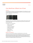
White Paper
Cisco Catalyst 3K-X Service Module: Enabling
Flexible NetFlow in the Access
Introduction
User mobility, virtualization, and a rapidly increasing number of applications make enterprise networks today more
complex and difficult to manage. Cisco® Flexible NetFlow provides complete visibility in the network, allowing
administrators to promptly react to security attacks and to effectively perform performance monitoring and network
troubleshooting tasks.
This white paper illustrates how Flexible NetFlow analysis can be extended to the access layer with the new uplink
service module available for Cisco Catalyst® 3560-X and 3750-X Series Switches.
Technology Overview
The new 10GE service module introduces line-rate Cisco TrustSec® MACsec and Flexible NetFlow in the Cisco
Catalyst 3560-X and 3750-X Series Switches.
Cisco Trustsec MACsec implements hop-by-hop data link encryption, making sure of complete data confidentiality
between two switches. How MACsec operates in the Cisco Catalyst 3560-X and 3750-X is illustrated in a separate
white paper.
Cisco Flexible NetFlow is a standard method, defined in RFC 3954, for computing user-configurable statistics on
traffic flowing through a particular network boundary. The new service module is capable of real-time Flexible
NetFlow analysis on traffic traversing its physical and logical interfaces.
Cisco Catalyst 3750-X Series Switches can stack with previous 3750-E, 3750-G, and 3750-V2 Series. Deploying
the service module in the stack enables Cisco Flexible NetFlow functionality across all switches in the stack, thus
realizing a true investment protection.
Product Information
This section provides information on how to order the service module and its software and hardware compatibility.
Table 1 lists the product IDs that can be used for ordering the 10GE service module for Cisco Catalyst 3560-X and
3750-X Series Switches.
Table 1.
Product IDs and Descriptions
Product ID
Description
C3KX-SM-10G
Two 10GbE SFP+ ports service module for Cisco Catalyst 3560-X and 3750-X
C3KX-SM-10G=
Two 10GbE SFP+ ports service module for Cisco Catalyst 3560-X and 3750-X (spare)
© 2011 Cisco and/or its affiliates. All rights reserved. This document is Cisco Public Information.
Page 1 of 14
The service module provides two dual-speed SFP+ ports, at initial release supporting the modules listed in Table 2.
Table 2.
Supported Modules
Product ID
Description
GLC-LH-SM=
Gigabit Ethernet SFP, LC connector LX/LH transceiver
GLC-SX-MM=
Gigabit Ethernet SFP, LC connector SX transceiver
GLC-ZX-SM=
1000BASE-ZX SFP
GLC-BX-D=
1000BASE-BX SFP, 1490 nm
GLC-BX-U=
1000BASE-BX SFP, 1310 nm
CWDM-SFP-xxxx=
CWDM xxxx nm SFP Gigabit Ethernet and 1G/2G Fibre Channel (FC)
DWDM-SFP-yyyy=
DWDM SFP 15yy.yy nm SFP (100 GHz ITU grid)
SFP-GE-S=
1000BASE-SX SFP module for MMF, 850 nm (DOM)2
SFP-GE-L=
1000BASE-LX/LH SFP module for SMF, 1300 nm (DOM)2
SFP-10G-LR=
10GBASE-LR SFP+ module
SFP-10G-SR=
10GBASE-SR SFP+ module
SFP-10G-LRM=
10GBASE-LRM SFP+ module
SFP-H10GB-CU1M=
10GBASE-CX1 SFP module
SFP-H10GB-CU3M=
10GBASE-CX3 SFP module
SFP-H10GB-CU5M=
10GBASE-CX5 SFP module
Support for copper 1000BASE-T and fiber 100BASE-FX module will be added in future Cisco IOS® Software
releases. An up to date list of supported transceivers can be found under “Cisco 10 Gigabit Ethernet Transceiver
Modules Compatibility Matrix” and “Cisco Gigabit Ethernet Transceiver Modules Compatibility Matrix”.
The service module is hot swappable and automatically detects the SFP speed as the existing 10GE Network
Module, C3KX-NM-10G. It is compatible with all 3560-X and 3750-X models, including the latest added WSC3750X-12S and 24S SFP switches.
The C3KX 10GE service module requires a Cisco Catalyst 3560-X or 3750-X switch with minimum version ID (VID)
02 or minimum H/W revision 0x03. The VID is visible on the label printed on the top cover of the switch or can be
retrieved using the following Cisco IOS Software CLI command: “show version | include Version ID”.
The H/W revision can be retrieved using the following Cisco IOS Software CLI commands:
●
For a 3560-X switch: “show version | include Hardware”
●
For 3750-X switches, stack or standalone: “remote command all show version | include Hardware”
As an example, the following Cisco IOS Software CLI output is taken from a stack of 3750-X switches that support
the service module:
3750-X#show version | include Switch 0|Version ID|System serial|Model number
Model number: WS-C3750X-48P-L
System serial number: FDO1530T0NS
Version ID: V02
Switch 02
Model number: WS-C3750X-48P-L
System serial number: FDO1530K1HG
Version ID: V02
© 2011 Cisco and/or its affiliates. All rights reserved. This document is Cisco Public Information.
Page 2 of 14
3750-X#remote command all show version | include Hardware
Switch: 1: (Master)
--------------------Hardware Board Revision Number: 0x03
Switch: 2:
--------------------Hardware Board Revision Number: 0x03
Cisco has been shipping switches compatible with the service module since January 2011. Refer to the account
manager for how to replace older revisions when ordering the service module.
In case the service module is plugged into an old hardware revision switch, Flexible NetFlow and MACsec
functionalities will be disabled: the service module will operate in “pass-through” mode, essentially behaving like a
10GE Network Module.
The minimal Cisco IOS Software release for the service module is 15.0(1)SE. Older Cisco IOS Software
revisions will not recognize the service module.
The license level required on the switch to support the service module is either IP Base or IP Services. A service
module inserted into a switch running LAN Base will operate in pass-through mode.
Software Compatibility for the Service Module
Differently from other field-replaceable uplink modules available for Cisco Catalyst 3560-X and 3750-X Series, the
service module has its own operating system, CPU, memory, switching fabric, and file system. This can enable
many sophisticated applications such as Flexible NetFlow, but from the software management perspective it
introduces an additional software subsystem in the switch or stack of switches. The version-numbering scheme for
the service module software is the same as in Cisco IOS Software.
The service module software is deployed through a software package, a .tar file, distinct from the Cisco IOS
Software image. Caveats can be tracked down to a particular version specifically for the service module software,
meaning it will be a new product in the Cisco Defect and Enhancement Tracking System (CDETS) system.
Software version incompatibility: A matching between the software version on the service module and the Cisco
IOS Software version on the stack (for example, 15.0(2)SE1 and 15.0(2)SE1) is expected; otherwise, a version
mismatch will occur (for example, 15.0(1)SE and 15.0(2)SE2). Versions of the service module can be retrieved
through the Cisco IOS Software command-line interface.
If within a particular Cisco IOS Software release, changes are not required in the service module software, as
might happen when the product has matured, a new version will be provided regardless. In this case the change
will be just the software version string and will be documented in the release notes.
With the simple compatibility schema just described and the implementation of the update requirements, there is
no need for a compatibility matrix to be maintained and documented. Let’s see its implications to the most
common situations seen by customers, where software compatibility needs to be assessed:
●
The service module is deployed in a stack of switches for the first time.
As the network is already undergoing maintenance, customer will make an assessment of the most suitable
software release and perform an update of all the subsystems in the stack, including the service module.
© 2011 Cisco and/or its affiliates. All rights reserved. This document is Cisco Public Information.
Page 3 of 14
●
The service module is added to an operational configuration already equipped with other service
modules or as a replacement of one of them.
Since the Cisco IOS Software major version currently installed is the real factor for the decision, the
customer might need to update the service module to a version either older or newer than the one
preinstalled by manufacturing, depending on the time the spare service module was ordered. In such case
the service disruption is minimal.
●
The service modules have already been deployed in the stack, and a particular bug fix (patch) or a
new functionality requires a software update on either the service module software or the stack
software or both.
All the subsystems in the stack will be updated.
Software Update Options for the Service Module
The service module software can be updated concurrently with Cisco IOS Software update or separately. In the
former case no additional service downtime is caused by the service module update, but longer image download
time due to the introduction of a new image. In the latter case, where only the service modules are updated, an inservice upgrade procedure is in place to guarantee minimal service disruption.
Simultaneous update with the switch chassis is achieved using the standard Cisco IOS Software CLI command
“archive download-sw” by providing the service module image bundle within the list of Cisco IOS Software images.
This is analogous to the case in which 3750V2 or 3750G switches are present in the same 3750-X stack, requiring
a c3750 image bundle to be specified within the image list.
Software compatibility is enforced by default: the update will be canceled if the new service module image is
incompatible with the new Cisco IOS Software image of the switch chassis. The compatibility check can be
removed by specifying the / no-version-check option. A service module running incompatible software will not be
able to perform Flexible NetFlow, but will still provide uplink traffic functionality, functioning in pass-through mode.
After images have been installed, the new software will be activated after reloading the switch or stack. This will as
well reboot and activate the new software on any service module in the switch/stack. The reload sequence is
accomplished by entering the “reload” command or by specifying the/reload option directly in the “archive
download-sw” CLI.
In a stack topology where only the service modules need to be updated and communication with the distribution
layer is implemented with at least two service modules, an in-service software update procedure is available. The
update procedure consists of the following steps:
1.
Install the new software image on all service modules in the stack, using the “archive download-sw
[/no-version-check] <service module image bundle>” CLI command. Do not include the / reload option.
2.
After the command completes successfully, reload one service module at a time and wait until the new
software is activated, using the following CLI command. To minimize switchover time, we recommend starting
from “standby” service modules and keeping the “active” service module for last:
switch <slot-number> fru-link reload
© 2011 Cisco and/or its affiliates. All rights reserved. This document is Cisco Public Information.
Page 4 of 14
The reboot progress of the service module will be reported through two different Cisco IOS Software SysLog
messages:
●
%PLATFORM_SM10G-3-NO_RESPONSE is shown right after the service module reload is executed and
simultaneously with all interface link up-down events pertaining to the service module itself.
●
%PLATFORM-6-FRULINK_INSERTED: occurs about 20 seconds after the previous event and indicates the
service module software is activated. Interface up-down events usually follow in about 5 seconds. At this
stage the service module is able to perform all of its networking functionalities but Flexible NetFlow.
●
%PLATFORM_SM10G-6-LINK_UP: occurring in about 3 minutes from the previous event, indicates that the
service module is able to operate normally in all its functions, including Flexible NetFlow.
3.
The service module status can be also retrieved by executing the Cisco IOS Software command “show switch
service-modules.”
Additional information on updating a stack with archive download-sw can be found in the Cisco Catalyst 3560-X
and 3750-X configuration guides.
Architecture Overview
The service module is designed with the objective of providing intelligent applications such as Flexible NetFlow
without affecting switch forwarding and processor (CPU) performances. In this perspective, a new programmable
application-specific integrated circuit (ASIC) with Flexible NetFlow analysis capabilities connects to data lines in the
switch port ASIC dedicated to uplink ports, and a new CPU is responsible for various Flexible NetFlow tasks other
than interacting with the switch CPU and controlling the service module ASIC.
The service module ASIC is the Flexible NetFlow engine performing traffic analysis for each flow monitor. Statistics
reside in the ASIC cache, which can store a total number of 32K flows shared across flow monitors.
The Flexible NetFlow software process running on the service module CPU consists of several components
performing the following tasks.
The service module ASIC controller receives the Cisco IOS Software Flexible NetFlow configuration from the
switch CPU running Cisco IOS Software and programs the service module ASIC accordingly.
The Flexible NetFlow process maintains a database of flow statistics cache for the purpose of flow aging and
serving queries coming through Cisco IOS Software CLI “show flow monitor <name> cache” commands.
Periodically every 30 seconds it sends flow records statistics to the switch CPU.
The exporter component handles the flow-aging mechanism and sends expired flow statistics to the configured
collectors. Flow export packets are sent to the switch ASIC, which performs the forwarding action (Figure 1).
© 2011 Cisco and/or its affiliates. All rights reserved. This document is Cisco Public Information.
Page 5 of 14
Figure 1.
Service Module Functional Block Diagram and Interaction with Switch
From what has been discussed so far, it is clear that the service module ASIC monitors packets traversing the
uplink ports. The analyzed traffic includes CPU traffic directed to or coming from uplinks. Additionally, it includes
downstream traffic received on the uplink ports that would be dropped by the switch, for example, because of an
access-control list (ACL) deny statement.
The service module ASIC does not analyze the following traffic categories:
●
Locally switched traffic incoming and exiting downlink ports
●
Traffic originated or terminated into the switch CPU that is going to or received from downlink ports
●
Upstream traffic directed to uplink ports that is dropped by the switch, for example, because of an ACL deny
statement
●
Ethernet management port (FastEthernet0) ingress and egress traffic
As the Flexible NetFlow engine is outside the switch ASIC logic, both the destination interface information for
downstream traffic and the source interface for upstream traffic are not available. The service module CPU hence
plays an important role in handling Layer 2 and Layer 3 cache received by the switch CPU every 20 seconds and
computing input/output interface fields for each flow. The interface value is based on destination/source MAC
address for switched traffic and IP destination/source address for routed traffic. In this perspective it is mandatory
that these fields be configured in the flow record.
Flexible NetFlow Fields in the Access Layer
Flexible NetFlow implemented by the service module at FCS time contains the standard Layer 2, Layer 3, and
Layer 4 fields and input/output physical interface information.
Of these, the following are particularly relevant for the access layer, as they carry information useful to identify the
end-user device and its traffic: MAC address, class of service (CoS), virtual LAN (VLAN), and input/output
interface.
© 2011 Cisco and/or its affiliates. All rights reserved. This document is Cisco Public Information.
Page 6 of 14
The data-link MAC destination/source address provides the unique identifier of the user device receiving/sending
traffic to the switch, along with information about the device vendor available from its organizationally unique
identifier (OUI).
The source and destination VLAN fields provide information on what switch VLAN is used by the traffic. Note that
source VLAN is available for flow monitors defined for the input (downstream) direction, while destination VLAN is
for the output (upstream) direction. Source and destination VLAN fields cannot be used together when monitoring a
particular direction.
The CoS field for output traffic provides the Layer 2 quality-of-service (QoS) priority value assigned to a flow by the
switch. In the opposite direction, the reported value is the one assigned by the other switches in the network facing
the service module ports.
The input/output interface value reports the Simple Network Management Protocol (SNMP) interface index value
for the physical interface the traffic is entering/exiting the switch. For example in the case of a downstream flow, the
input interface value refers to a port on the service module, while the output interface value refers to a downlink
port. The latter can be used to track the location of the user device, when integrated with information coming from a
wired location database and with cable length measured by Cisco time domain reflectometry (TDR).
Performance
Each service module is capable of handling 32,000 flows at the same time. The number of monitors supported
depends on their record definition. For records including Layer 2 and Layer 3 fields, it is possible to have up to 128
simultaneous monitors.
In is important noting that these numbers scale with the number of service modules in the stack: for example, 4
service modules in the stack can store 128,000 flows and have 512 simultaneous monitors. This is different from
other resources in the stack, for example, ternary content-addressable memory (TCAM) space and CPU memory,
which do not increase when adding new stack members.
As explained in the "Architecture Overview" section, there is no switch CPU degradation due to exporting flows, as
this task is totally performed by the service module itself. There is no hard limit to the number of exporters defined:
the service module was successfully tested with 10 exporters per monitor.
Exporting flows minimally affects data traffic bandwidth either, due to the design of Cisco Flexible NetFlow. It is
worth mentioning that Layer 3 priority can be configured for exported packets to avoid being dropped in case of
congestion.
Flexible NetFlow in Access
Enabling NetFlow at the access switch maximizes end-user traffic visibility. In fact, it is possible to correlate the
device location information, provided by the interface port number connecting to the endpoint, with its unique
address at data link and network layer. As identity functions such as user authentication are taking place in the
access layer, adding identity awareness is the natural evolution for future Flexible NetFlow implementations.
Cisco Flexible NetFlow envisions a distributed architecture, where NetFlow monitoring is performed real time in
various points of the network and information is sent to centralized collectors for further analysis and offline data
mining. As the number of access switches is typically greater than distribution and core, they can scale better and
make sure there are no performance effects of oversubscription at aggregation and core.
© 2011 Cisco and/or its affiliates. All rights reserved. This document is Cisco Public Information.
Page 7 of 14
Finally, accuracy of NetFlow statistics can be better achieved closer to the endpoint being monitored, where packet
drops due to congestion or traffic policing are minor compared to aggregation and core.
Configuration Examples and Notes
This section provides some configuration example for Flexible NetFlow and illustrates some of the commands in
detail. Additional information on how to configure Flexible NetFlow on the service module is available under the
software configuration guides for Cisco Catalyst 3560-X and 3750-X Series.
Flexible NetFlow objects are modular and can be used for different monitoring requirements. The flow record
defines what header fields need to be analyzed. If the result of the Flexible NetFlow analysis can be viewed as a
table, where rows represent each distinct traffic flow, then the flow record is where the user can:
●
Define the table columns.
●
Define which of the columns are key fields. A key field controls the flow uniqueness: when the Flexible
NetFlow engine observes a new value of a key column, it creates a new row. Nonkey fields are for
computed values, typically counters or time stamps that characterize quantity and duration of each flow.
The following are two examples of a flow record, including Layer 2, Layer 3, and Layer 4 fields. Key fields are
defined using the “match” keyword, while nonkey fields use the “collect” keyword.
flow record L2L4input
description L2 IPv4 L4 fields for input downstream monitor
match datalink source-vlan-id
match datalink ethertype
match datalink mac source-address
match datalink mac destination-address
match ipv4 protocol
match ipv4 source address
match ipv4 destination address
match transport source-port
match transport destination-port
collect interface input snmp
collect interface output snmp
collect counter flows
collect counter bytes
collect counter packets
collect timestamp sys-uptime first
collect timestamp sys-uptime last
flow record L2L4output
description L2 IPv4 L4 fields for output upstream monitor
match datalink destination-vlan-id
match datalink ethertype
match datalink dot1q priority
match datalink mac source-address
match datalink mac destination-address
match ipv4 tos
© 2011 Cisco and/or its affiliates. All rights reserved. This document is Cisco Public Information.
Page 8 of 14
match ipv4 protocol
match ipv4 source address
match ipv4 destination address
match transport source-port
match transport destination-port
match transport tcp flags
collect interface input snmp
collect interface output snmp
collect counter flows
collect counter bytes
collect counter packets
collect timestamp sys-uptime first
collect timestamp sys-uptime last
It can be observed how interface fields are available as nonkey fields as they are actually a computed value by the
flow post processing in the service module CPU, as explained in the "Architecture Overview" section.
Another observation is on the importance of the IP protocol field, as a way to determine the presence of IPv6 traffic
even if the network has no IPv6 configured. Endpoints running dual IPv4 and IPv6 network stacks are increasingly
being deployed in the access network, offering a potentially undisturbed field to malicious attackers who want to
exploit IPv6 vulnerabilities.
The following list explains how the preceding Flexible NetFlow fields can be used for different network
administration tasks:
●
Destination and source address at data link and IP layer, together with the interface value, define uniquely
the flow endpoints.
●
Application or service analysis can be based on the following fields: data link ethertype, IP protocol,
transport source and destination port, IP source and destination address.
●
The class of service (CoS) expressed by the “datalink dot1q priority” field and the type of service (ToS) field
can be used to validate quality-of-service (QoS) settings in the network.
●
Finally, destination IP address, Transmission Control Protocol (TCP) flags and transport destination port
can be used to monitor excessive usage of SYN bits, which is typical of a port scan caused by a malware.
The flow exporter is the Flexible NetFlow modular object where the collector IP address and User Datagram
Protocol (UDP) port are defined, together with the differentiated services code point (DSCP) and time-to-live (TTL)
value for NetFlow Data Export (NDE) traffic.
An important exporter parameter is the source interface, which is used to compute the source IP address for NDE
traffic, which identifies the switch to the collector. Typically the source interface is the management interface of the
switch. Note that at first customer ship (FCS) neither Virtual Routing and Forwarding (VRF) awareness nor IPv6
addressing is supported.
The third object is the flow monitor, which basically consists of a Flexible NetFlow profile to be attached to the
interface direction (input or output) being analyzed. It includes a flow record and one or multiple exporters.
© 2011 Cisco and/or its affiliates. All rights reserved. This document is Cisco Public Information.
Page 9 of 14
Within the several characteristics of the flow monitor, one of the most requiring a customization is the “cache active
timeout,” which defines the flow-aging frequency expressed in seconds. In other words, it affects the granularity of
the statistics and the minimum time to react to a cyber security attack. It should be configured following the
collector recommendations, or in their absence a typical setting is one minute.
Deployment with Private VLAN
As explained in the architecture section, traffic that is locally switched within the stack and does not traverse the
service module is not monitored and consequently not visible in the Flexible NetFlow records. Although the amount
of locally switched traffic is typically a small fraction, this can represent a concern when Flexible NetFlow is used
for cyber security or forensic purposes.
Private VLAN (PVLAN) can overcome this limitation by preventing local switching and forcing the traffic to go
through the service module ports. The solution consists in the access 3560-X switch or 3750-X stack acting as a
Layer 2 device and the distribution switch as a Layer 3 gateway with local proxy Address Resolution Protocol
(ARP) functionality enabled within the VLAN(s) used by directly connected devices.
Figure 2 is an example where PVLAN edge, or protected ports, is used. Locally switched traffic is exchanged
between two workstations in the same subnet, both connected to a stack of Cisco Catalyst 3750-X switches.
Figure 2.
How to Monitor Locally Switched Traffic (Left) with Private VLAN (Right) for Layer 2 Configured Switch or Stack
The following flow for outbound traffic shows how the traffic incoming the switch access port and destined to the
second workstation goes through the service module interface.
LAYER 2 DESTINATION VLAN ID:
20
DATALINK ETHERTYPE:
0x0800
MAC SOURCE ADDRESS:
0000.0400.0002
MAC DESTINATION ADDRESS:
503d.e5fb.adcb
IPV4 SOURCE ADDRESS:
11.1.10.102
IPV4 DESTINATION ADDRESS:
11.1.10.103
TRNS SOURCE PORT:
1024
TRNS DESTINATION PORT:
80
© 2011 Cisco and/or its affiliates. All rights reserved. This document is Cisco Public Information.
Page 10 of 14
interface input snmp index:
10608
interface output snmp index:
10202
Symmetrically a flow with the same data link, IPv4 and transport information is computed for inbound monitored
traffic:
LAYER 2 DESTINATION VLAN ID:
20
DATALINK ETHERTYPE:
0x0800
MAC SOURCE ADDRESS:
503d.e5fb.adcb
MAC DESTINATION ADDRESS:
0000.0400.0003
IPV4 SOURCE ADDRESS:
11.1.10.102
IPV4 DESTINATION ADDRESS:
11.1.10.103
TRNS SOURCE PORT:
1024
TRNS DESTINATION PORT:
80
The MAC source and destination in the preceding flows clearly show the two Layer 2 hops: the first to the Switch
Virtual Interface (SVI) on the distribution switch, the second to the destination workstation.
Deployment with Remote SPAN and Flow-Based SPAN
Analyzing locally switched or routed traffic can also be achieved by sending a copy of the traffic through the service
module ports by enabling Switched Port Analyzer (SPAN) monitoring. Compared to the PVLAN deployment, this
solution does not require the access switch to act as a Layer 2 only device. Furthermore, the mirrored traffic can
also include CPU and ACL dropped traffic that would not reach the service module ASIC otherwise.
A remote SPAN (RSPAN) session is configured on the access and distribution switches to monitor the access
VLAN(s) received traffic. With flow-based SPAN, locally switched traffic characteristics can be exactly matched
with an ACL filter applied to the RSPAN session. The locally switched traffic is mirrored on a remote SPAN
destination VLAN and carried on the service module ports configured as trunks.
The configuration example in Figure 3 takes into account the same scenario addressed in the example with
PVLAN: locally switched traffic is exchanged between two workstations in the same subnet, both connected to a
stack of Cisco Catalyst 3750-X switches.
© 2011 Cisco and/or its affiliates. All rights reserved. This document is Cisco Public Information.
Page 11 of 14
Figure 3.
Monitoring Locally Switched or Routed Traffic with Flow-Based Remote SPAN
The following is the flow resulting from the mirrored RSPAN traffic:
LAYER 2 DESTINATION VLAN ID:
666
DATALINK ETHERTYPE:
0x0800
MAC SOURCE ADDRESS:
0000.0400.0002
MAC DESTINATION ADDRESS:
0000.0400.0003
IPV4 SOURCE ADDRESS:
11.1.10.102
IPV4 DESTINATION ADDRESS:
11.1.10.103
TRNS SOURCE PORT:
1024
TRNS DESTINATION PORT:
80
interface input snmp index:
0
interface output snmp index:
10202
The differences with the PVLAN case are the VLAN ID, which is the RSPAN destination VLAN instead of the
original access VLAN, and the fact that the input interface in the flow record is null (0) and the output interface is
the service module port. The actual input and output interfaces can still be retrieved on the collector flow records
for outbound traffic, by looking up the MAC and IPv4 source and destination address.
Exporting to Ethernet Management port
The Ethernet management port (FastEthernet0) is a dedicated routed interface used for out-of-band switch
management services such as Telnet, Secure Shell (SSH) Protocol, Trivial File Transfer Protocol (TFTP), and
SNMP.
The service module FNF software injects exported traffic directly into the switch ASIC, where the forwarding is
performed. By design, forwarding to/from FastEthernet0 from/to the switch ASIC is blocked in Cisco Catalyst 3560X and 3750-X switches.
© 2011 Cisco and/or its affiliates. All rights reserved. This document is Cisco Public Information.
Page 12 of 14
For the preceding reason exporting flows to a collector through the Ethernet management port is unsupported at
FCS. Flow exports directed to FastEthernet0 are reported as successfully sent by Cisco IOS Software CLI “show
flow exporter” statistics. This is currently tracked under this caveat: CSCtt05810.
Appendix
This section discusses how Flexible NetFlow and software update functionality on the service module interoperate
with other features implemented by Cisco Catalyst 3560-X and 3750-X switches.
Interaction with EEM
At FCS time, Flexible NetFlow statistics generated by the service module cannot be used by the Embedded Event
Manager subsystem using the “event nf” Cisco IOS Software CLI command. This functionality will be implemented
in the future.
Interaction with TrustSec MACsec
As traffic encryption performed by TrustSec MACsec occurs in the service module physical layer chip (PHY), there
is no effect on Flexible NetFlow functionality caused by enabling MACsec, and encrypted traffic can be monitored.
Interaction with Smart Logging and Telemetry
The Flexible NetFlow feature can be enabled simultaneously with smart logging and telemetry (SLT) on the same
switch.
SLT is a Cisco IOS Software feature that consents exporting to a Flexible NetFlow capable collector statistics
related to security violation events. In its first implementation, part of Cisco IOS Software Release 12.2(58)SE1, it
supports the following type of events:
●
Dynamic ARP inspection violation
●
IP source guard violation
●
Dynamic Host Configuration Protocol (DHCP) snooping violation
●
Port ACL logging for IP denied or permitted traffic
Detailed information on SLT can be found in the Cisco Catalyst 3560-X and 3750-X configuration guides under the
section “Configuring System Message Logging and Smart Logging.”
SLT can share the same exporter with the Flexible NetFlow functionality performed by the service module.
When a certain packet received by the switch ASIC triggers any of the events for which smart logging is enabled, a
copy is sent to the switch CPU, which processes its content and exports it to the collector. Note that processing
and exporting packets do not occur automatically for SLT-enabled event categories, but are carried on by a distinct
process, the SLT handler, that has to be explicitly activated by the global configuration command “logging
smartlog.”
Clearly, SLT complements Flexible NetFlow analysis with real-time information on security violations that
potentially cannot be seen by the NetFlow collector, as for instance violating or denied traffic received on the
downlink ports is dropped by the switch ASIC before traversing the service module.
© 2011 Cisco and/or its affiliates. All rights reserved. This document is Cisco Public Information.
Page 13 of 14
As SLT is performed in the switch CPU, it can affect its performance. Particular precaution should be observed
when activating ACL smart logging, as the traffic size can be significantly high. In such case, monitoring CPU
performance is highly recommended. There are two process names shown in the “show processes cpu” related to
ACL smart logging: “slthandler” is the SLT handler process mentioned earlier, and “HACL queue” is the queue
handler for copy packets generated by the ACL. As an example, in situations where the number of logged packets
is around 100,000 per second, these two processes could consume up to 15 percent and 35 percent of the CPU
time, respectively, bringing the CPU utilization at 90 percent.
Software Update with EEM
EEM can be used to fully automate the service module software update when a version mismatch with Cisco IOS
software occurs. A simple EEM script can detect the service module version mismatch SysLog message and
perform the archive download and the service module reload in sequence. This is very useful when the service
module is moved from a stack to another running a different Cisco IOS Software version, or it replaces an existing
one or finally when a network module is upgraded to a service module.
Software Update with Rolling Stack Upgrade
Rolling stack upgrade is a feature that minimizes the network disruption during Cisco IOS software update for
Layer 2 stacks with redundant uplink modules. Rolling stack upgrade is also available when the stack is equipped
with at least two service modules. Refer to the “Managing Switch Stacks” section in the Cisco Catalyst 3560-X and
3750-X configuration guide for further information.
For More Information
Refer to the following documents:
●
Cisco Catalyst 3560-X 3750-X software configuration guide
●
Cisco Catalyst 3560-X 3750-X hardware installation guide
●
Cisco Flexible NetFlow white paper
Printed in USA
© 2011 Cisco and/or its affiliates. All rights reserved. This document is Cisco Public Information.
C11-691508-00
11/11
Page 14 of 14