1
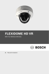
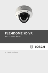
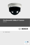
FLEXIDOME HD VR
NIN-733 / NIN-832 / NIN-932
en
Installation Manual
FLEXIDOME HD VR
Table of Contents | en
3
Table of Contents
1
Safety
6
1.1
Safety precautions
6
1.2
Important safety instructions
7
1.3
Connection in applications
8
1.4
Type label
8
1.5
FCC & ICES compliance
1.6
MicroSD cards
10
9
1.7
UL certification
10
1.8
Bosch notices
11
1.9
Copyrights
12
2
Introduction
13
2.1
Features
13
3
System Information
14
3.1
Network video server
14
3.1.1
Progressive scan
14
3.1.2
True Day/Night function
14
3.1.3
Multiple streams
14
3.1.4
ONVIF (Open Network Video Interface Forum)
14
3.1.5
Audio
15
3.1.6
Alarm I/O
15
3.1.7
Tamper detection and motion detection
15
3.1.8
Video encoding
15
3.1.9
Multicast
15
3.1.10
Power-over-Ethernet
15
3.1.11
Encryption
15
3.1.12
Recording
16
3.1.13
Configuration
16
3.2
Operation with external systems
17
4
Planning
18
4.1
Unpacking
18
4.2
System requirements
18
Bosch Security Systems
Installation Manual
AM18-Q0637 | v1.1 | 2014.11
4
en | Table of Contents
FLEXIDOME HD VR
5
Installation
19
5.1
Parts
19
5.2
Mounting the unit
20
5.2.1
Surface mounting
20
5.2.2
Flush mount
21
5.3
Connections
22
5.3.1
Make the connections
22
5.4
Mount the camera
25
5.5
Controls
26
5.6
Camera positioning and field-of-view
27
5.6.1
Pan
28
5.6.2
Tilt
28
5.6.3
Twist
29
5.7
Using the install wizard
30
5.7.1
Adjustment procedure
30
5.8
Closing the unit
31
6
Camera configuration
33
6.1
User modes
33
6.2
Day/Night switching
33
7
Browser connection
34
7.1
Protected network
34
8
Troubleshooting
35
8.1
Function test
35
8.2
Resolving problems
36
8.3
Customer service
38
9
Maintenance
39
9.1
Testing the network connection
39
9.2
Cleaning the bubble
39
9.3
Repairs
40
9.3.1
Transfer and disposal
40
10
Technical Data
41
10.1
Specifications
41
AM18-Q0637 | v1.1 | 2014.11
Installation Manual
Bosch Security Systems
FLEXIDOME HD VR
10.1.1
Table of Contents | en
Dimensions
Bosch Security Systems
5
47
Installation Manual
AM18-Q0637 | v1.1 | 2014.11
6
en | Safety
FLEXIDOME HD VR
1
Safety
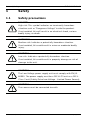
1.1
Safety precautions
DANGER!
High risk: This symbol indicates an imminently hazardous
situation such as "Dangerous Voltage" inside the product.
If not avoided, this will result in an electrical shock, serious
bodily injury, or death.
WARNING!
Medium risk: Indicates a potentially hazardous situation.
If not avoided, this could result in minor or moderate bodily
injury.
CAUTION!
Low risk: Indicates a potentially hazardous situation.
If not avoided, this could result in property damage or risk of
damage to the unit.
CAUTION!
The Low Voltage power supply unit must comply with EN/UL
60950. The power supply must be a SELV-LPS unit or a SELV Class 2 unit (Safety Extra Low Voltage - Limited Power Source).
CAUTION!
The camera must be connected to earth.
AM18-Q0637 | v1.1 | 2014.11
Installation Manual
Bosch Security Systems
FLEXIDOME HD VR
1.2
Safety | en
7
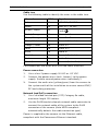
Important safety instructions
Read, follow, and retain for future reference all of the following
safety instructions. Follow all warnings on the unit and in the
operating instructions before operating the unit.
1.
Clean only with a dry cloth. Do not use liquid cleaners or
aerosol cleaners.
2.
Do not install unit near any heat sources such as radiators,
heaters, stoves, or other equipment that produce heat.
Avoid exposure to direct sunlight for long periods.
3.
Never spill liquid of any kind on the unit.
4.
Take precautions to protect the unit from power and
lightning surges.
5.
Adjust only those controls specified in the operating
instructions.
6.
Operate the unit only from the type of power source
indicated on the label.
7.
Unless qualified, do not attempt to service a damaged unit
yourself. Refer all servicing to qualified service personnel.
8.
Install in accordance with the manufacturer's instructions
in accordance with applicable local codes. Use only
attachments/accessories specified by the manufacturer.
Equipment change or modification could void the user's
guarantee or authorization agreement.
9.
Connect the yellow/green earth wire of the camera to the
system earth of the installation to ensure correct safety
and EMC/RFI protection.
Bosch Security Systems
Installation Manual
AM18-Q0637 | v1.1 | 2014.11
8
en | Safety
1.3
FLEXIDOME HD VR
Connection in applications
Grounding
The yellow/green safety (power) ground wire from the camera
must be connected to the system earth of the installation.
U.S.A.: - section 810 of the National Electrical Code, ANSI/NFPA
No.70, provides information regarding proper grounding.
12 VDC / 24 VAC power source: This unit is intended to
operate with a limited power source. The unit is intended to
operate at either 12 VDC or 24 VAC (if PoE is not available).
User supplied wiring must be in compliance with electrical
codes (Class 2 power levels).
PoE: Use only certified PoE devices. Power-over-Ethernet can
be connected at the same time as a 12 VDC or 24 VAC power
supply.
If auxiliary power (12 VDC or 24 VAC) and PoE are applied
simultaneously, the camera selects auxiliary input and shuts off
the PoE.
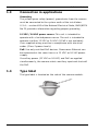
1.4
Type label
The type label is located on the side of the camera module.
AM18-Q0637 | v1.1 | 2014.11
Installation Manual
Bosch Security Systems
FLEXIDOME HD VR
1.5
Safety | en
9
FCC & ICES compliance
FCC & ICES Information
This equipment has been tested and found to comply with the
limits for a Class B digital device, pursuant to part 15 of the
FCC Rules. These limits are designed to provide reasonable
protection against harmful interference in a residential
installation. This equipment generates, uses, and can radiate
radio frequency energy and, if not installed and used in
accordance with the instructions, may cause harmful
interference to radio communications. However, there is no
guarantee that interference will not occur in a particular
installation. If this equipment does cause harmful interference
to radio or television reception, which can be determined by
turning the equipment off and on, the user is encouraged to try
to correct the interference by one or more of the following
measures:
–
reorient or relocate the receiving antenna;
–
increase the separation between the equipment and
receiver;
–
connect the equipment into an outlet on a circuit different
from that to which the receiver is connected;
–
consult the dealer or an experienced radio/TV technician
for help.
Intentional or unintentional modifications, not expressly
approved by the party responsible for compliance, shall not be
made. Any such modifications could void the user's authority to
operate the equipment. If necessary, the user should consult
the dealer or an experienced radio/television technician for
corrective action.
The user may find the following booklet, prepared by the
Federal Communications Commission, helpful: "How to Identify
and Resolve Radio-TV Interference Problems". This booklet is
available from the U.S. Government Printing Office,
Washington, DC 20402, Stock No. 004-000-00345-4.
Bosch Security Systems
Installation Manual
AM18-Q0637 | v1.1 | 2014.11
10
en | Safety
1.6
FLEXIDOME HD VR
MicroSD cards
Bosch Security systems recommends that local storage on
microSD card should only be used for alarm recording and
Automatic Network Replenishment (ANR) applications. To
minimize the risk of loss of digital information, we recommend
multiple, redundant recording systems, and a procedure to
back up all digital information.
1.7
UL certification
Disclaimer
Underwriter Laboratories Inc. ("UL") has not tested the
performance or reliability of the security or signaling aspects of
this product. UL has only tested fire, shock and/or casualty
hazards as outlined in UL's Standard(s) for Safety for Information
Technology Equipment, UL 60950-1. UL Certification does not
cover the performance or reliability of the security or signaling
aspects of this product.
UL MAKES NO REPRESENTATIONS, WARRANTIES, OR
CERTIFICATIONS WHATSOEVER REGARDING THE
PERFORMANCE OR RELIABILITY OF ANY SECURITY OR
SIGNALING RELATED FUNCTIONS OF THIS PRODUCT.
Disposal - Your Bosch product was developed and
manufactured with high-quality material and components that
can be recycled and reused. This symbol means that
electronic and electrical appliances, which have reached the
end of their working life, must be collected and disposed of
separately from household waste material. Separate collecting
systems are usually in place for disused electronic and
electrical products. Please dispose of these units at an
environmentally compatible recycling facility, per European
Directive 2012/19/EU
AM18-Q0637 | v1.1 | 2014.11
Installation Manual
Bosch Security Systems
FLEXIDOME HD VR
1.8
Safety | en
11
Bosch notices
Video loss
Video loss is inherent to digital video recording; therefore,
Bosch Security Systems cannot be held liable for any damage
that results from missing video information. To minimize the
risk of lost digital information, Bosch Security Systems
recommends multiple, redundant recording systems, and a
procedure to back up all analog and digital information.
Optical elements
Optical elements are sensitive and should be protected at all
times. Do not allow objects to come into contact with glass
surfaces and do not touch optical elements with your fingers.
Copyright
This manual is the intellectual property of Bosch Security
Systems and is protected by copyright.
All rights reserved.
Trademarks
All hardware and software product names used in this
document are likely to be registered trademarks and must be
treated accordingly.
Note
This manual has been compiled with great care and the
information it contains has been thoroughly verified. The text
was complete and correct at the time of printing. The ongoing
development of the products may mean that the content of the
user guide can change without notice. Bosch Security Systems
accepts no liability for damage resulting directly or indirectly
from faults, incompleteness or discrepancies between the user
guide and the product described.
More information
For more information please contact the nearest Bosch Security
Systems location or visit www.boschsecurity.com
Bosch Security Systems
Installation Manual
AM18-Q0637 | v1.1 | 2014.11
12
en | Safety
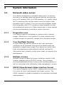
1.9
FLEXIDOME HD VR
Copyrights
The firmware uses the fonts "Adobe-Helvetica-Bold-R-Normal-24-240-75-75-P-138-ISO10646-1" and "Adobe-Helvetica-Bold-RNormal--12-120-75-75-P-70-ISO10646-1" under the following
copyright:
Copyright 1984-1989, 1994 Adobe Systems Incorporated.
Copyright 1988, 1994 Digital Equipment Corporation.
Permission to use, copy, modify, distribute and sell this
software and its documentation for any purpose and without
fee is hereby granted, provided that the above copyright
notices appear in all copies and that both those copyright
notices and this permission notice appear in supporting
documentation, and that the names of Adobe Systems and
Digital Equipment Corporation not be used in advertising or
publicity pertaining to distribution of the software without
specific, written prior permission.
This software is based in part on the work of the Independent
JPEG Group.
AM18-Q0637 | v1.1 | 2014.11
Installation Manual
Bosch Security Systems
FLEXIDOME HD VR
Introduction | en
2
Introduction
2.1
Features
13
The FLEXIDOME HD Vandal-Resistant (VR) IP Day/Night camera
is a high-performance, surveillance color camera.
The analog video output of the camera can be used
simultaneously with an IP stream to allow operation in hybrid
mode. The IP video stream uses H.264 compression technology
to give clear images while reducing bandwidth and storage
requirements. It is also ONVIF compliant to improve
compatibility during system integration.
The camera operates as a network video server and transmits
video and control signals over data networks, such as Ethernet
LANs and the Internet. The camera is easy to install and ready
to use. Features include:
–
Progressive scan CMOS HD sensor
–
Aesthetic vandal-resistant enclosure
–
True Day/Night performance with switchable IR filter
–
High performance lenses for HD resolution and extra DoF
–
Automatic motorized focus and zoom adjustment
–
Multiple streams
–
MicroSD card slot
–
ONVIF conformant
–
Two-way audio and audio alarm
–
Alarm input and alarm output to external devices
–
Intelligent dynamic noise reduction
–
Enhanced video motion detection
–
Video transmission over IP networks
–
Multicast function
–
Integrated Ethernet interface (10/100 Base-T)
–
Power-over-Ethernet (PoE)
–
Password protection
–
Integrated Web server for live viewing and configuration via
a browser
–
Firmware update through flash memory
–
Hybrid video outputs
Bosch Security Systems
Installation Manual
AM18-Q0637 | v1.1 | 2014.11
14
en | System Information
FLEXIDOME HD VR
3
System Information
3.1
Network video server
The camera incorporates a network video server. Its primary
function is to encode video and control data for transmission
over an IP network. With its H.264 encoding, it is ideally suited
for IP communication and for remote access to digital video
recorders and IP systems. The use of existing networks means
that integration with CCTV systems or local networks can be
achieved quickly and easily. Video images from a single camera
can be simultaneously received on several receivers.
3.1.1
Progressive scan
The camera captures and processes progressively scanned
images. When there is fast motion in a scene, progressively
scanned images are generally sharper than interlaced images.
3.1.2
True Day/Night function
In night mode, the camera enhances low light viewing by
switching the IR (infrared) filter out of the optical path and
providing a monochrome image. The camera can switch from
color to monochrome mode automatically by sensing the
illumination level, manually via the alarm input, or remotely via a
web browser.
3.1.3
Multiple streams
Multiple streams enable the camera to deliver several H.264
streams together with an M-JPEG stream. These streams
facilitate bandwidth-efficient viewing and recording options as
well as integration with third-party video management systems.
3.1.4
ONVIF (Open Network Video Interface Forum)
The camera complies to the ONVIF standard which means that
it is easier to install and integrate into larger systems. The
ONVIF standard is a global standard for the interface of network
video products.
AM18-Q0637 | v1.1 | 2014.11
Installation Manual
Bosch Security Systems
FLEXIDOME HD VR
3.1.5
System Information | en
15
Audio
Two-way duplex audio is available in the unit for live voice
communications or audio recording.
3.1.6
Alarm I/O
The alarm input can be used to control the functionality of the
unit. An alarm output can control external devices.
3.1.7
Tamper detection and motion detection
The camera offers a wide range of configuration options for
alarm signaling in the event of tampering with the camera. A
Motion+ algorithm for detecting movement in the video image is
included.
3.1.8
Video encoding
The camera uses the H.264 compression standards. Thanks to
efficient encoding, the data rate remains low even with high
image quality and can also be adapted to local conditions
within wide limits.
3.1.9
Multicast
In suitably configured networks, the multicast function enables
simultaneous, real time transmission to multiple receivers. The
prerequisite for this is that the UDP and IGMP V2/V3 protocols
are implemented on the network.
3.1.10
Power-over-Ethernet
Power for the camera can be supplied via a Power-overEthernet compliant network cable connection. With this
configuration, only a single cable connection is required to
view, power, and control the camera.
3.1.11
Encryption
The unit offers a variety of options for protection against
unauthorized reading. Web browser connections can be
protected using HTTPS. Protect the control channels via the
SSL encryption protocol. With an additional license, the user
data itself can be encrypted.
Bosch Security Systems
Installation Manual
AM18-Q0637 | v1.1 | 2014.11
16
en | System Information
3.1.12
FLEXIDOME HD VR
Recording
The camera can be used with an iSCSI server connected via the
network to store long-term recordings, and with a local
microSD card for shorter storage times and temporary
recordings.
3.1.13
Configuration
The camera can be configured using a browser on the local
network (Intranet) or from the Internet. Similarly, firmware
updates and rapid loading of device configurations are also
possible. Configuration settings can be stored as files on a
computer and copied from one camera to another.
AM18-Q0637 | v1.1 | 2014.11
Installation Manual
Bosch Security Systems
FLEXIDOME HD VR
3.2
System Information | en
17
Operation with external systems
The camera can be used with a variety of Bosch systems:
–
Bosch Video Management System
–
Bosch Video Client
–
Bosch Recording Station
When connected to any of these systems, many of the camera
configuration parameters are controlled by the system and not
by the settings made via a web browser.
Bosch Video Management System
The Bosch Video Management System is a unique enterprise IP
video surveillance solution that provides seamless management
of digital video, audio, and data across any IP network. It is
designed to work with Bosch CCTV products as part of a total
video surveillance management system.
Bosch Video Client
The camera video server and the Bosch Video Client software
combine to provide a high-performance system solution. The
Bosch Video Client is a Windows application for viewing,
operating, controlling, and administering CCTV installations
(such as surveillance systems) at remote locations.
Bosch Recording Station
The camera is also designed for use with the Bosch Recording
Station. The Bosch Recording Station can record up to 64 video
and audio streams. The Bosch Recording Station supports
various functions of the camera, such as controlling relays,
remote control of peripheral devices, and remote configuration.
It can use alarm inputs to trigger actions and, when motion
detection Motion+ is active, can record the relevant cells,
making intelligent motion detection possible.
Bosch Security Systems
Installation Manual
AM18-Q0637 | v1.1 | 2014.11
18
en | Planning
FLEXIDOME HD VR
4
Planning
4.1
Unpacking
Unpack carefully and handle the equipment with care. The
packaging contains:
–
FLEXIDOME HD VR IP camera
–
Torx screwdriver bit
–
Camera mounting kit
–
Mounting template
–
RJ45 female-to-female network cable connector
–
–
Optical disk
–
Manuals
–
Bosch Video Client
Quick install instructions and safety instructions
If equipment has been damaged during shipment, repack it in
the original packaging and notify the shipping agent or supplier.
4.2
System requirements
–
Computer with Windows XP/Vista/7 operating system,
network access, and Microsoft Internet Explorer web
browser version 9.
-or-
–
Computer with network access and reception software, for
example Bosch Video Client or Bosch Video Management
System.
AM18-Q0637 | v1.1 | 2014.11
Installation Manual
Bosch Security Systems
FLEXIDOME HD VR
5
Installation | en
19
Installation
CAUTION!
Installation should only be performed by qualified service
personnel in accordance with the National Electrical Code or
applicable local codes.
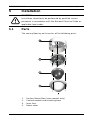
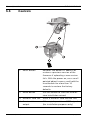
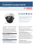
5.1
Parts
The camera/housing unit consists of the following parts:
1.
2.
3.
4.
Bosch Security Systems
Surface Mount Box (some models only)
Camera module and mounting base
Inner liner
Dome cover
Installation Manual
AM18-Q0637 | v1.1 | 2014.11
20
en | Installation
FLEXIDOME HD VR
5.2
Mounting the unit
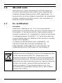
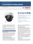
5.2.1
Surface mounting
9.5 mm (0.375 in)
Ø
8
m
m
3x
3x
PCD 123 mm (4.84 in)
To mount the camera on the surface of a wall or ceiling:
1.
Use the surface mount box as a template to mark the holes
indicated in the drawing. The PCD is 123 mm (4.84 in).
2.
Drill three holes with a diameter of 8 mm (0.3 in).
3.
Insert the supplied plugs into the holes.
4.
Attach the surface mount box securely using the three
supplied screws.
5.
If you use the side connection of the SMB, remove the cap
covering the side entrance, otherwise, leave the cap in
place.
AM18-Q0637 | v1.1 | 2014.11
Installation Manual
Bosch Security Systems
FLEXIDOME HD VR
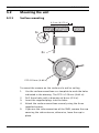
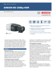
5.2.2
Installation | en
21
Flush mount
105 (4.13)
Ø
8
m
m
3x
3x
57.6
(2.27)
66.5
(2.62)
33.3
(1.31)
57.6
(2.27)
PCD: 133 (5.25)
To flush mount the camera in a wall or ceiling:
1.
Use the mounting template to mark out the recess and to
mark the holes indicated in the drawing. The PCD is
133 mm (5.25 in)
2.
Cut out the recess.
3.
Drill three holes with a diameter of 8 mm (0.3 in).
4.
Insert the supplied plugs into the holes.
5.
Partially insert two screws into the mounting holes.
Bosch Security Systems
Installation Manual
AM18-Q0637 | v1.1 | 2014.11
22
en | Installation
6.
FLEXIDOME HD VR
Using one of the keyholes, hang the mounting base of the
camera module on one screw temporarily; tilt the base
slightly to gain access to the cable connections.
7.
5.3
Make the connections as outlined in section 5.3 below.
Connections
CAUTION!
Isolate unused power wires individually to prevent shortcircuits.
Check the type label on the the camera module for the correct
power ratings.
5.3.1
Make the connections
Connection box
The unit has connection terminals on flying leads. In wet or
outdoor installations make use of a field wiring box with
NEMA Type 4X or IP66 protection level or better.
1.
Make the connections inside a water tight compartment.
Isolate unused power wires individually.
2.
After connections are made ensure that the watertight
compartment is tightly closed and cables and conduits are
properly sealed to prevent ingress of water.
AM18-Q0637 | v1.1 | 2014.11
Installation Manual
Bosch Security Systems
FLEXIDOME HD VR
Installation | en
23
Cable tree
Use the following table to identify the wires in the cable tree:
Wire color
AWG
Signal
Red
26
+12 VDC / 24 VAC
Brown
26
GND DC / 24 VAC
Yellow / Green
24
Black / Orange
28
Alarm Out A
White / Orange
28
Alarm Out B
White / Violet
28
Ground (Alarm In)
Orange / Violet
28
Alarm In 1
Violet
28
Alarm In 2
Earth
White
28
Audio In
(Shield)
28
Ground (Audio In)
Black
28
Audio Out
(Shield)
28
Ground (Audio Out)
For connections use wires of at least the same thickness.
Power connection
1.
2.
Use a class 2 power supply 24 VAC or +12 VDC.
Connect the power wires (red+ , brown-) to the power
supply. (Isolate unused power wires individually.)
3.
Connect the earth wire (yellow/green) from the camera to
the system earth of the installation to ensure correct EMC/
RFI and safety protection.
Network (and PoE) connection
1.
Use a shielded twisted pair (STP) Category 5e cable,
maximum length 100 meters.
2.
Use the RJ45 female-to-female network cable connector to
connect the network cable of the system to the RJ45
connector of the camera (Auto MDIX compliant automatically detects the cable connection type).
Power is supplied to the camera via the Ethernet cable,
compliant with the Power-over-Ethernet standard.
Bosch Security Systems
Installation Manual
AM18-Q0637 | v1.1 | 2014.11
24
en | Installation
FLEXIDOME HD VR
CAUTION!
Use an isolation transformer to avoid ground loops.
Ground loops can cause bad picture performance.
Analog video output
Connect to the BNC connector to obtain an analog video signal.
This is a CVBS 1 Vpp PAL or NTSC signal (depending on the
selected camera base frequency).
Alarm Input
Use the alarm input to connect external alarm devices such as
door contacts or sensors. A zero potential make or break
contact can be used as the actuator (use a bounce-free contact
system).
–
Refer to the cable tree table to identify the wire colors for
connecting the alarm input.
–
Configurable as active low or active high.
Alarm output
Use the alarm relay output for switching external devices such
as lamps or sirens.
–
Refer to the cable tree table to identify the wire colors for
connecting the alarm output.
–
In the menu system, configure the relay output to operate
as either normally open (NO) or normally closed (NC).
Audio in / Audio out
The unit has full-duplex mono audio. The two-way
communication can be used to connect a speaker or door
AM18-Q0637 | v1.1 | 2014.11
Installation Manual
Bosch Security Systems
FLEXIDOME HD VR
Installation | en
25
intercom system. The audio input signal is transmitted in sync.
with the video signal.
Refer to the cable tree table to identify the wire colors for
connecting the audio input and output.
Audio in: Line input level (not suitable for direct microphone
signal).
Audio out: Line output level (not suitable for direct speaker
connection).
Wiring: Shielded audio connection cable is advised.
5.4
Mount the camera
1.
Route the cable tree from the camera around the rear of
the camera module and secure all cables.
2.
Attach the camera module securely using the three
supplied screws.
Bosch Security Systems
Installation Manual
AM18-Q0637 | v1.1 | 2014.11
26
en | Installation
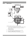
5.5
FLEXIDOME HD VR
Controls
1. Reset button
Restores the default IP address or
restores a previous version of the
firmware if uploading a new version
fails. With the power on, use a small
pointed object to press and hold the
reset button for more than 10
seconds to restore the factory
defaults.
2. Menu button
Use this button to start the field-of view installation wizard.
3. MicroSD card slot
Insert a microSD card into the slot.
4. Service video
2.5 mm jack provides a CVBS signal
output
AM18-Q0637 | v1.1 | 2014.11
(for installation purposes only)
Installation Manual
Bosch Security Systems
FLEXIDOME HD VR
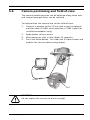
5.6
Installation | en
27
Camera positioning and field-of-view
The camera module position can be adjusted along three axes
and several zoom positions can be selected.
To help position the camera and set the field-of-view:
1.
Connect a monitor to the 2.5 mm jack using the optional
monitor cable (S1460) which provides a CVBS signal (for
installation purposes only).
2.
Apply power to the camera.
3.
After power-up, wait a little (about 20 seconds).
4.
Press the Menu button. This stops the IP video stream and
enables the service video analog output.
S1460
FoV
CAUTION!
Do not expose the sensors to direct sunlight.
Bosch Security Systems
Installation Manual
AM18-Q0637 | v1.1 | 2014.11
28
en | Installation
5.6.1
FLEXIDOME HD VR
Pan
For horizontal adjustment (pan):
1.
Rotate the camera module (1) in the base. Do not rotate
2.
Tighten the locking screw (2) with the supplied
more than 180° in either direction.
screwdriver bit.
5.6.2
Tilt
For vertical adjustment (tilt):
1.
Loosen the two thumbwheels (1).
2.
Swing the camera module between the wings. Do not
3.
Tighten the two thumbwheels (1).
rotate more than 90°.
≤90°
AM18-Q0637 | v1.1 | 2014.11
Installation Manual
Bosch Security Systems
FLEXIDOME HD VR
5.6.3
Installation | en
29
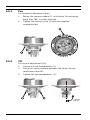
Twist
To obtain a horizontal horizon (for tilted ceilings or sidewall
mounting), twist the camera module to align the picture shown
on the monitor.
Bosch Security Systems
Installation Manual
AM18-Q0637 | v1.1 | 2014.11
30
en | Installation
5.7
FLEXIDOME HD VR
Using the install wizard
The Menu button on the control panel is used to access the
camera install wizard. When there is a choice in the wizard, the
options are selected by either a short press (less than 2 s) or a
long press (more than 2 s) of the button.
The wizard handles the following functions:
–
Lens identification
–
Image orientation
–
Zoom and focus adjustment conditions
–
Auto focus
–
Analog output
Run the wizard to select orientation and field-of-view (zoom).
Note:
The zoom and focus are adjusted again later (with the dome
bubble in place) via the web browser. This optimizes picture
sharpness in both bright and low-level lighting.
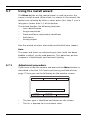
5.7.1
Adjustment procedure
If you have set up the camera and pressed the Menu button as
described in Section 5.6 Camera positioning and field-of-view,
page 27 then you see the following on the monitor screen:
Lens type:
CONTINUE
<press short>
State:
180° ROTATE
<press long>
Focus Indicator: 0
Timeout: 300
–
The lens type is identified and shown on the screen.
–
The iris is opened to its maximum value.
AM18-Q0637 | v1.1 | 2014.11
Installation Manual
Bosch Security Systems
FLEXIDOME HD VR
1.
Installation | en
31
To rotate the image 180°, press and hold the Menu button
until the image flips.
2.
Briefly press the Menu button to set the start position for
the automatic motorized focus adjustment.
–
You will hear the motorized automatic back focus
process running.
–
3.
The progress is shown on the monitor.
Briefly press the Menu button again and again to scroll
through the preset zoom positions.
–
The selection loops back to the beginning when you
reach the last one.
4.
When you reach the desired zoom position, use a long
press of the Menu button to set the zoom position and to
re-focus.
5.
If the camera is not correctly focussed, press the Menu
button for a longer time to restart the wizard.
If the camera is correctly focussed, press the Menu button
for a short time to change the analog output.
6.
To change the analog output state, press the Menu button
for a short time.
–
Briefly press the Menu button again and again to
select NTSC on, PAL on or OFF (default).
7.
When the selection is made, use a long press of the Menu
button to save the results.
–
The zoom and focus position is stored.
–
The iris is set to its original value.
–
The video service output is disabled.
–
The BNC video output is set to its selected state.
Note:
If the BNC video output is set to On, the second IP stream is
disabled.
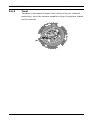
5.8
Closing the unit
When the camera position is set and all adjustments have been
made, close the unit.
Bosch Security Systems
Installation Manual
AM18-Q0637 | v1.1 | 2014.11
32
en | Installation
FLEXIDOME HD VR
1.
Disconnect the service cable from the video jack.
2.
Place the inner liner in position aligning its fin with the
bracket on the base.
3.
Using the supplied screwdriver bit, secure the dome
bubble to the camera base by tightening the three screws.
AM18-Q0637 | v1.1 | 2014.11
Installation Manual
Bosch Security Systems
FLEXIDOME HD VR
6
Camera configuration | en
33
Camera configuration
The camera normally provides an optimal picture without the
need for further adjustments. Configuration of the camera is
carried out via the network using a web browser.
6.1
User modes
The camera has six user modes. These modes contain
optimized settings for a variety of applications. Select the mode
most suited to the camera’s function via the web browser
interface.
6.2
Day/Night switching
The camera is equipped with a motorized IR filter. The
mechanical IR filter is taken out of the optical path in low-light
applications.
The IR filter is controlled either:
–
via an alarm input, or
–
automatically, based on the observed light levels.
If Auto switching mode is selected, the camera automatically
switches the filter depending on the observed light level. The
switching level is programmable.
Note:
When the auto mode is selected and the switching level is set
to -15, certain borderline scene lighting conditions can cause
the camera to switch back and forth between day and night
modes. Set a different switching level to avoid this.
Bosch Security Systems
Installation Manual
AM18-Q0637 | v1.1 | 2014.11
34
en | Browser connection
7
FLEXIDOME HD VR
Browser connection
A computer with Microsoft Internet Explorer can be used to
receive live images from the camera, control the camera, and
replay stored sequences. The camera is configured over the
network using the browser.
The configuration options using the menu system of the camera
itself are limited to setting up the lens and network.
Note:
The camera can also be configured using the supplied Bosch
Video Client or the Bosch Video Management System.
7.1
Protected network
If a RADIUS server is used for network access control (802.1x
authentication), the camera must be configured first. To
configure the camera for a Radius network, connect it directly
to a PC via a crossed network cable and configure the two
parameters, Identity and Password. Only after these have been
configured can communication with the camera via the network
occur.
AM18-Q0637 | v1.1 | 2014.11
Installation Manual
Bosch Security Systems
FLEXIDOME HD VR
Troubleshooting | en
8
Troubleshooting
8.1
Function test
35
The camera offers a variety of configuration options. Therefore,
check that it works properly after installation and configuration.
This is the only way to ensure that the camera will function as
intended in the event of an alarm.
Your check should include the following functions:
–
Can you connect to the camera remotely?
–
Does the camera transmit all the data required?
–
Does the camera respond as desired to alarm events?
–
Is it possible to control peripheral devices, if necessary?
Bosch Security Systems
Installation Manual
AM18-Q0637 | v1.1 | 2014.11
36
en | Troubleshooting
8.2
FLEXIDOME HD VR
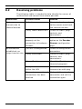
Resolving problems
The following table is intended to help identify the causes of
malfunctions and correct them where possible.
Malfunction
Possible causes
Solution
No image
Defective camera.
Connect a local monitor
transmission to
to the camera and check
remote location.
the camera function.
Faulty cable connections. Check all cables, plugs,
contacts and
connections.
No connection
Incorrect encoder stream
Select the H.264 MP SD
property set for
option on the Encoder
connection to hardware
Streams configuration
decoder.
page.
The unit's configuration.
Check all configuration
established, no
parameters.
image transmission. Faulty installation.
Check all cables, plugs,
contacts and
connections.
Wrong IP address.
Check the IP addresses
(terminal program).
AM18-Q0637 | v1.1 | 2014.11
Faulty data transmission
Check the data
within the LAN.
transmission with ping.
The maximum number of
Wait until there is a free
connections has been
connection and call the
reached.
transmitter again.
Installation Manual
Bosch Security Systems
FLEXIDOME HD VR
Troubleshooting | en
37
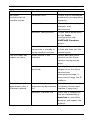
Malfunction
Possible causes
Solution
No audio
Hardware fault.
Check that all connected
transmission to
audio units are operating
remote station.
correctly.
Faulty cable connections. Check all cables, plugs,
contacts and
connections.
Incorrect configuration.
Check audio parameters
on the Audio
configuration and
LIVEPAGE Functions
pages.
The audio voice
Wait until the connection
connection is already in
is free and then call the
use by another receiver.
sender again.
The unit does not
Alarm source is not
Select possible alarm
report an alarm.
selected.
sources on the Alarm
sources configuration
page.
No alarm response
Specify the desired alarm
specified.
response on the Alarm
connections
configuration page; if
necessary change the IP
address.
Have the unit checked by
The unit is not
Power failure during
operational after a
programming by firmware Customer Service and
firmware upload.
file.
replace if necessary.
Incorrect firmware file.
Enter the IP address of
the unit followed by /
main.htm in your Web
browser and repeat the
upload.
Bosch Security Systems
Installation Manual
AM18-Q0637 | v1.1 | 2014.11
38
en | Troubleshooting
FLEXIDOME HD VR
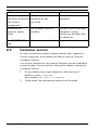
Malfunction
Possible causes
Solution
Placeholder with a
JVM not installed on your
Install JVM on your
red cross instead of
computer or not
computer.
the ActiveX
activated.
components.
Web browser
Active proxy server in
Create a rule in the local
contains empty
network.
computer's proxy
fields.
settings to exclude local
IP addresses.
The POWER LED is
Firmware upload failed.
Repeat firmware upload.
red.
8.3
Customer service
If a fault cannot be resolved, please contact your supplier or
system integrator, or go directly to Bosch Security Systems
Customer Service.
The version numbers of the internal firmware can be viewed on
a special page. Please note this information before contacting
Customer Service.
1.
In the address bar of your browser, after the unit IP
address, enter: /version
for example: 192.168.0.1/version
2.
Write down the information or print out the page.
AM18-Q0637 | v1.1 | 2014.11
Installation Manual
Bosch Security Systems
FLEXIDOME HD VR
Maintenance | en
9
Maintenance
9.1
Testing the network connection
39
The ping command can be used to check the connection
between two IP addresses. This allows testing whether a device
is active in the network.
1.
Open the DOS command prompt.
2.
Type ping followed by the IP address of the device.
If the device is found, the response appears as " Reply from ... ",
followed by the number of bytes sent and the transmission time
in milliseconds. Otherwise, the device cannot be accessed via
the network. This might be because:
–
The device is not properly connected to the network.
Check the cable connections in this case.
–
The device is not correctly integrated into the network.
Check the IP address, subnet mask, and gateway address.
9.2
Cleaning the bubble
The exterior of the bubble is hard coated for extra protection. If
cleaning becomes necessary, only use cleaning solutions and
cloths suitable for cleaning safety glass lenses. Dry the bubble
thoroughly with a dry nonabrasive cloth to prevent water spots.
Never scrub the bubble with any abrasive material or cleaners.
–
Do not use abrasive or highly alkaline cleaners on the
–
Do not scrape the bubble with razor blades or other sharp
bubble.
instruments.
–
Do not use Benzene, Gasoline, Acetone, or Carbon
Tetrachloride on the bubble.
–
Do not clean bubbles in the hot sun or on very hot days
Bosch Security Systems
Installation Manual
AM18-Q0637 | v1.1 | 2014.11
40
en | Maintenance
9.3
FLEXIDOME HD VR
Repairs
CAUTION!
Never open the casing of the unit. The unit does not contain any
user serviceable parts. Ensure that all maintenance or repair
work is performed only by qualified personnel (electrical
engineering or network technology specialists). In case of
doubt, contact your dealer's technical service center.
9.3.1
Transfer and disposal
The camera should only be passed on together with this
installation guide. The unit contains environmentally hazardous
materials that must be disposed of according to law. Defective
or superfluous devices and parts should be disposed of
professionally or taken to your local collection point for
hazardous materials.
AM18-Q0637 | v1.1 | 2014.11
Installation Manual
Bosch Security Systems
FLEXIDOME HD VR
Technical Data | en
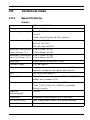
10
Technical Data
10.1
Specifications
41
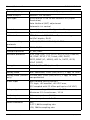
NIN-932
Imager
1/3-inch CMOS HD sensor
Image resolution
1920 × 1080 pixels
Rated supply voltage
24 VAC 50/60 Hz
12 VDC
Power-over-Ethernet 48 VDC nominal
Current consumption
600 mA (12 VDC)
500 mA (24 VAC)
175 mA (PoE 48 VDC)
Minimum illumination 0.25 lx Color, 30 IRE
Lens 3-9 mm, F1.2
0.08 lx Mono, 30 IRE
Minimum illumination 0.45 lx Color, 30 IRE
Lens 10-23 mm, F1.6
0.15 lx Mono, 30 IRE
Day/Night
Color, Mono (IR contrast), Auto
Dynamic range
> 90 dB typical
Noise reduction
Intelligent Dynamic Noise Reduction (iDNR) with
separate temporal and spatial adjustments
BLC
Off/Auto/IntelligentAE
White Balance
ATW, AWB hold and manual (2500 to 10000K)
Indoor and Outdoor ATW
Shutter
Automatic Electronic Shutter (AES)
Fixed (1/30 [1/25] to 1/150000) selectable
Default shutter
Contrast
On/Off
enhancement
Sharpness
Sharpness enhancement level selectable
Privacy Masking
Four independent areas, fully programmable
Video Analysis
Motion+, IVA
Bosch Security Systems
Installation Manual
AM18-Q0637 | v1.1 | 2014.11
42
en | Technical Data
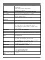
Lens type
FLEXIDOME HD VR
3 to 9 mm or 10 to 23 mm varifocal SR (Super
Resolution)
Auto Varifocal (AVF) adjustment
Automatic iris control
Controls
Via web browser or Configuration Manager
User modes
6 pre-defined customizable user modes
LAN interface
STP, Ethernet 10/100 Base-T, auto-sensing,
half/full duplex, RJ45
Video encoding
H.264 (ISO/IEC 14496-10), M-JPEG
protocols
Stream (max.)
1080p25/30
Group of pictures
IP, IBP, IBBP
Network protocols
IPv4, IPv6, UDP, TCP, HTTP, HTTPS, RTP, IGMPV2/
V3, ICMP, RTSP, FTP, Telnet, ARP, DHCP,
SNTP,SNMP (V1, MIB-II), 802.1x, SMTP, iSCSI,
UPnP (SSDP)
Encryption
TLS 1.0, SSL, AES (optional)
Analog video
BNC connector, CVBS (PAL/NTSC), 1 Vpp, 75 Ohm
Analog video (service
2.5 mm jack, CVBS (PAL/NTSC), 1 Vpp, 75 Ohm,
only)
non-protected
Alarm input
Non-isolated closing contact
TTL logic, +5V nominal, +40 VDC max,
(DC coupled with 22 kOhm pull-up to +3.3 VDC)
Relay output
Maximum voltage 30 VAC or +40 VDC
Audio input
1 Vrms, impedance 12 kOhm
Audio output
1 Vrms, impedance 1.5 kOhm
Audio standards
AAC
Maximum 0.5 A continuous, 10 VA
G.711, 8kHz sampling rate
L16, 16kHz sampling rate
Audio signal-to-noise
> 50 dB
ratio
AM18-Q0637 | v1.1 | 2014.11
Installation Manual
Bosch Security Systems
FLEXIDOME HD VR
Technical Data | en
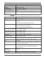
Memory card slot
Supports SDHC and SDXC microSD cards
Weight
0.84 kg (1.85 lb)
Environment
IP 66, NEMA Type 4X
Impact protection
IK10
Operating
-30 °C to +50 °C (-22 °F to +122 °F)
43
temperature
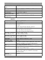
NIN-832
Imager
1/2.7-inch CMOS HD sensor
Image resolution
1920 × 1080 pixels
Rated supply voltage
24 VAC 50/60 Hz
12 VDC
Power-over-Ethernet 48 VDC nominal
Current consumption
500 mA | 600 mA IVA (12 VDC)
450 mA | 500 mA IVA (24 VAC)
150 mA | 175 mA IVA (PoE 48 VDC)
Minimum illumination 0.22 lx Color, 30 IRE
Lens 3-9 mm, F1.2
0.05 lx Mono, 30 IRE
Minimum illumination 0.4 lx Color, 30 IRE
Lens 10-23 mm, F1.6
0.1 lx Mono, 30 IRE
Day/Night
Color, Mono (IR contrast), Auto
Dynamic range
Digital WDR: 76 dB
Noise reduction
Intelligent Dynamic Noise Reduction (iDNR) with
separate temporal and spatial adjustments
BLC
Off/Auto
White Balance
ATW, AWB hold and manual (2500 to 10000K)
Shutter
Automatic Electronic Shutter (AES)
Indoor and Outdoor ATW
Fixed (1/30 [1/25] to 1/150000) selectable
Default shutter
Contrast
On/Off
enhancement
Sharpness
Bosch Security Systems
Sharpness enhancement level selectable
Installation Manual
AM18-Q0637 | v1.1 | 2014.11
44
en | Technical Data
FLEXIDOME HD VR
Privacy Masking
Four independent areas, fully programmable
Video Analysis
Motion+, IVA versions
Lens type
3 to 9 mm or 10 to 23 mm varifocal SR (Super
Resolution)
Auto Varifocal (AVF) adjustment
Automatic iris control
Controls
Via web browser or Configuration Manager
User modes
6 pre-defined customizable user modes
LAN interface
STP, Ethernet 10/100 Base-T, auto-sensing,
half/full duplex, RJ45
Video encoding
H.264 (ISO/IEC 14496-10), M-JPEG
protocols
Stream (max.)
1080p25/30
Group of pictures
IP, IBP, IBBP
Network protocols
IPv4, IPv6, UDP, TCP, HTTP, HTTPS, RTP, IGMPV2/
V3, ICMP, RTSP, FTP, Telnet, ARP, DHCP,
SNTP,SNMP (V1, MIB-II), 802.1x, SMTP, iSCSI,
UPnP (SSDP)
Encryption
TLS 1.0, SSL, AES (optional)
Analog video
BNC connector, CVBS (PAL/NTSC), 1 Vpp, 75 Ohm
Analog video (service
2.5 mm jack, CVBS (PAL/NTSC), 1 Vpp, 75 Ohm,
only)
non-protected
Alarm input
Non-isolated closing contact
TTL logic, +5V nominal, +40 VDC max,
(DC coupled with 22 kOhm pull-up to +3.3 VDC)
Relay output
Maximum voltage 30 VAC or +40 VDC
Maximum 0.5 A continuous, 10 VA
Audio input
1 Vrms, impedance 12 kOhm
Audio output
1 Vrms, impedance 1.5 kOhm
Audio standards
AAC
G.711, 8kHz sampling rate
L16, 16kHz sampling rate
AM18-Q0637 | v1.1 | 2014.11
Installation Manual
Bosch Security Systems
FLEXIDOME HD VR
Audio signal-to-noise
Technical Data | en
45
> 50 dB
ratio
Memory card slot
Supports SDHC and SDXC microSD cards
Weight
0.84 kg (1.85 lb)
Environment
IP 66, NEMA Type 4X
Impact protection
IK10
Operating
-30 °C to +50 °C (-22 °F to +122 °F)
temperature
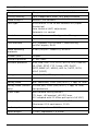
NIN-733
Imager
1/3-inch CMOS HD sensor
Image resolution
1280 × 720 pixels
Rated supply voltage
24 VAC 50/60 Hz
12 VDC
Power-over-Ethernet 48 VDC nominal
Current consumption
500 mA | 600 mA IVA (12 VDC)
450 mA | 500 mA IVA (24 VAC)
150 mA | 175 mA IVA (PoE 48 VDC)
Minimum illumination 0.017 lx Color, 30 IRE
Lens 3-9 mm, F1.2
0.0057 lx Mono, 30 IRE
Minimum illumination 0.03 lx Color, 30 IRE
Lens 10-23 mm, F1.6
0.01 lx Mono, 30 IRE
Day/Night
Color, Mono (IR contrast), Auto
Dynamic range
84 dB
Noise reduction
Intelligent Dynamic Noise Reduction (iDNR) with
separate temporal and spatial adjustments
BLC
Off, Auto, IntelligentAE (BLC)
White Balance
ATW, AWB hold and manual (2500 to 10000K)
Indoor and Outdoor ATW
Shutter
Automatic Electronic Shutter (AES)
Fixed (1/30 [1/25] to 1/150000) selectable
Default shutter
Contrast
On/Off
enhancement
Bosch Security Systems
Installation Manual
AM18-Q0637 | v1.1 | 2014.11
46
en | Technical Data
FLEXIDOME HD VR
Sharpness
Sharpness enhancement level selectable
Privacy Masking
Four independent areas, fully programmable
Video Analysis
Motion+, IVA versions
Lens type
3 to 9 mm or 10 to 23 mm varifocal SR (Super
Resolution)
Auto Varifocal (AVF) adjustment
Automatic iris control
Controls
Via web browser or Configuration Manager
User modes
6 pre-defined customizable user modes
LAN interface
STP, Ethernet 10/100 Base-T, auto-sensing,
half/full duplex, RJ45
Video encoding
H.264 (ISO/IEC 14496-10), M-JPEG
protocols
Stream (max.)
720p60
Group of pictures
IP, IBP, IBBP
Network protocols
IPv4, IPv6, UDP, TCP, HTTP, HTTPS, RTP, IGMPV2/
V3, ICMP, RTSP, FTP, Telnet, ARP, DHCP,
SNTP,SNMP (V1, MIB-II), 802.1x, SMTP, iSCSI,
UPnP (SSDP)
Encryption
TLS 1.0, SSL, AES (optional)
Analog video
BNC connector, CVBS (PAL/NTSC), 1 Vpp, 75 Ohm
Analog video (service
2.5 mm jack, CVBS (PAL/NTSC), 1 Vpp, 75 Ohm,
only)
non-protected
Alarm input
Non-isolated closing contact
TTL logic, +5V nominal, +40 VDC max,
(DC coupled with 22 kOhm pull-up to +3.3 VDC)
Relay output
Maximum voltage 30 VAC or +40 VDC
Maximum 0.5 A continuous, 10 VA
Audio input
1 Vrms, impedance 12 kOhm
Audio output
1 Vrms, impedance 1.5 kOhm
AM18-Q0637 | v1.1 | 2014.11
Installation Manual
Bosch Security Systems
FLEXIDOME HD VR
Audio standards
Technical Data | en
47
AAC
G.711, 8kHz sampling rate
L16, 16kHz sampling rate
Audio signal-to-noise
> 50 dB
ratio
Memory card slot
Supports SDHC and SDXC microSD cards
Weight
0.84 kg (1.85 lb)
Environment
IP 66, NEMA Type 4X
Impact protection
IK10
Operating
-30 °C to +50 °C (-22 °F to +122 °F)
temperature
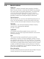
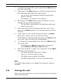
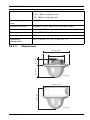
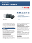
10.1.1
Dimensions
Ø158 (6.22)
85 (3.35)
39 (1.54)
Ø95 (3.7)
mm (in)
141 (5.55)
Ø158 (6.22)
mm (in)
Bosch Security Systems
Installation Manual
AM18-Q0637 | v1.1 | 2014.11
48
en | Technical Data
AM18-Q0637 | v1.1 | 2014.11
FLEXIDOME HD VR
Installation Manual
Bosch Security Systems
Bosch Security Systems
www.boschsecurity.com
© Bosch Security Systems, 2014