1
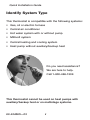
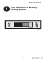
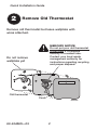
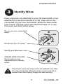
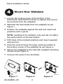
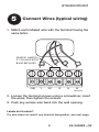
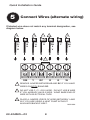
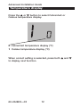
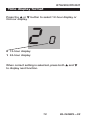
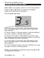
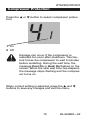
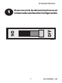
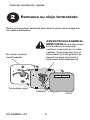
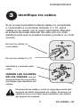
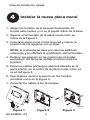
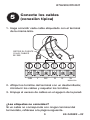
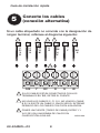
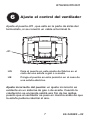
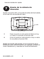
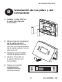
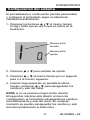
Quick Installation Guide
RTH2300/RTH221
Programmable Thermostat
69-2448ES-03
Quick Installation Guide
Identify System Type
This thermostat is compatible with the following systems:
• Gas, oil or electric furnace
• Central air conditioner
• Hot water system with or without pump
• Millivolt system
• Central heating and cooling system
• Heat pump without auxiliary/backup heat
Do you need assistance?
We are here to help.
Call 1-800-468-1502.
This thermostat cannot be used on heat pumps with
auxiliary/backup heat or on multistage systems.
69-2448ES—03
ii
RTH2300/RTH221
1
Turn Off Power to Heating/
Cooling System
M28097
1
69-2448ES—03
Quick Installation Guide
2
Remove Old Thermostat
Remove old thermostat but leave wallplate with
wires attached.
MERCURY NOTICE
Do not put your old thermostat
in the trash if it contains
mercury in a sealed tube.
Contact your local waste
management authority for
instructions regarding recycling
and proper disposal.
Do not remove
wallplate yet
Old thermostat
Cover
69-2448ES—03
M28099
2
RTH2300/RTH221
3
Identify Wires
If any wires are not attached to your old thermostat or are
attached to a terminal marked C or C1, they will not be
connected to your new thermostat. Wrap the bare metal
end of each of these wires with electrical tape, so it cannot touch and short other wires.
Do not use non-connected
wires.
Do not use C or C1 wires.
Identify and label each wire.
IGNORE WIRE COLORS:
Use terminal screw
designations to identify
wires.
M29988
Disconnect wires and remove the old wallplate only after
all wires are labeled. Wrap the wires around a pencil to
prevent them from falling though the wall opening.
3
69-2448ES—03
Quick Installation Guide
4
Mount New Wallplate
1. Loosen the locking screw at the bottom of the
thermostat. Note that the screw is captive and cannot
be removed from the wallplate.
2. Separate the thermostat from the wallplate as per
Figure 1.
3. Position the wallplate against the wall and mark hole
positions with a pencil.
NOTE: Levelling is for esthetics only and will not affect
the performance of the thermostat.
4. Drill holes at the marked positions and insert supplied
wall anchors.
5. Pass the wires through the large opening located at
the bottom center of the wallplate as per Figure 2.
6. Secure the wallplate to the wall with supplied mounting
screws as per Figure 3.
7. Connect the wires to the terminals.
M32154
Figure 1
69-2448ES—03
Figure 2
4
Figure 3
RTH2300/RTH221
5
Connect Wires (typical wiring)
1. Match each labeled wire with the terminal having the
same letter.
REMOVE JUMPER
IF YOU HAVE BOTH
R AND RC WIRES
O/B
Y
RC
R
G
W
M32155A
2. Loosen the terminal screws using a screwdriver, insert
the wires, then tighten the screws.
3. Push any excess wire back into the wall opening.
Labels don’t match?
If a wire does not match any terminal designation, see next page.
5
69-2448ES—03
Quick Installation Guide
5
Connect Wires (alternate wiring)
If labeled wire does not match any terminal designation, see
diagram below.
2
OR
C1
X
B
3
OR
B
H
OR
Y1
M
1
1
OR
R
3
OR
RH
4
V
OR
F
OR
W1
H
1
O/B
Y
RC
R
G
W
1
REMOVE JUMPER BETWEEN R AND RC IF YOU HAVE
WIRES ON BOTH R AND RC.
2
DO NOT USE C, C1, OR X WIRE. DO NOT USE B WIRE
IF YOU ALREADY HAVE 0 WIRE. WRAP BARE END OF
WIRE WITH ELECTRICAL TAPE.
3
PLACE A JUMPER (PIECE OF WIRE) BETWEEN Y AND
W IF YOU ARE USING A HEAT PUMP WITHOUT
AUXILIARY/BACKUP HEAT.
M32169A
69-2448ES—03
6
RTH2300/RTH221
6
Set Heating Fan Control
Set jumper JP1, on the back of the thermostat, if you
have connected a wire to the G terminal.
JP1
HG
Leave the jumper in this factory-set position if
you have a gas or oil furnace.
HE
Place the jumper to this position if you have
an electric furnace.
Incorrect jumper setting: An incorrect setting is noticeable in a gas or oil heating system. When heating starts,
you will initially feel cold air coming out of the vents as
the fan is running before the furnace has enough time to
heat up the air.
7
69-2448ES—03
Quick Installation Guide
7
Set Heat Pump Reversing Valve
Set jumper JP2, on the back of the thermostat, if you
have a heat pump.
JP2
O
Leave the jumper in this factory-set position if
you have connected O wire to the O/B terminal.
B
Place the jumper to this position if you have
connected B wire to the O/B terminal.
Incorrect jumper setting: The heat pump operation will
be reversed, i.e., it will cool in Heat mode and will heat in
Cool mode.
69-2448ES—03
8
RTH2300/RTH221
8
Install Batteries and
Thermostat
1. Install 2 AAA batteries
on the back of the
thermostat.
2. Align the two brackets
on the top of the
thermostat with the
corresponding slots
on the top of the
wallplate.
3. Push the thermostat
against the wallplate.
4. Tighten the screw
at the bottom of the
thermostat.
5. Turn power back on
at the heating/cooling
system.
M28098
9
69-2448ES—03
Advanced Installation
System setup.......................................................................11
Temperature display............................................................12
Time display format............................................................13
Heating cycles per hour......................................................14
Compressor protection.......................................................15
Customer assistance..........................................................16
Limited warranty..................................................................17
RTH2300/RTH221
About your
System
setup
new thermostat
Follow the procedure below to personalize and configure the thermostat according to the heating/cooling
system.
1. Press and hold the s and t buttons simultaneously
(for three seconds) until the display appears as
shown below.
WIRING
Function number
Option number
ASSISTANCE
2. Press the s or t button to change the option.
3. Press the s and t buttons simultaneously for one
second to advance to the next function.
NOTE: If you do not press any button for 60 seconds
while you are in the setup menu, the thermostat automatically saves any changes made and exits the menu.
At any time you can save the changes and exit by
pressing the Run button.
11
69-2448ES—03
TROUBLESHOOTING
4. When the last function is displayed, press the s and
t buttons to save any changes and exit the menu.
Advanced Installation Guide
About your new
Temperature
display
thermostat
WIRING
Press the s or t button to select Fahrenheit or
Celsius temperature display.
0 Fahrenheit temperature display (°F)
When correct setting is selected, press both s and t
to display next function.
TROUBLESHOOTING
ASSISTANCE
1 Celsius temperature display (°C)
69-2448ES—03
12
RTH2300/RTH221
Aboutdisplay
Time
your new
format
thermostat
Press the s or t button to select 12-hour display or
24-hour display.
WIRING
20
0 12-hour display
1 24-hour display
ASSISTANCE
When correct setting is selected, press both s and t
to display next function.
TROUBLESHOOTING
13
69-2448ES—03
Advanced Installation Guide
Heating cycles per hour
Note: Make sure system switch is in the heat position.
Press the s or t button to select your heating
system and optimize its operation:
ASSISTANCE
WIRING
2 to 6 cycles per hour
3
5
5 12 min, Gas or oil furnace. Use this setting if you
have a standard gas or oil furnace that is less than
90% efficient.
2 30 min, Steam or gravity system. Use this setting if
you have a steam or gravity heat system.
TROUBLESHOOTING
3 20 min, Hot water or high-efficiency furnace: Use
this setting if you have a hot water system or a gas furnace of greater than 90% efficiency.
4 15 min, Gas or oil furnace. Use this setting if you
have a standard gas or oil furnace that is less than
90% efficient.
6 10 min, Electric furnace: Use this setting if you have
any type of electric heating system.
When correct setting is selected, press both s and t
to display next function.
69-2448ES—03
14
RTH2300/RTH221
Compressor Protection
Press the s or t button to select compressor protection:
WIRING
41
1 On
0 Off
15
69-2448ES—03
TROUBLESHOOTING
When correct setting is selected, press the s and t
buttons to save any changes and exit the menu.
ASSISTANCE
Damage can occur if the compressor is
restarted too soon after shutdown. This feature forces the compressor to wait 5 minutes
before restarting. During the wait time, the
message Cool On or Heat On flashes on the
screen. When the safe wait time has elapsed,
the message stops flashing and the compressor turns on.
Advanced Installation Guide
About yourassistance
Customer
new thermostat
TROUBLESHOOTING
ASSISTANCE
WIRING
For assistance with this product, please visit
http://yourhome.honeywell.com or call Honeywell Customer
Care toll-free at 1-800-468-1502.
69-2448ES—03
16
RTH2300/RTH221
About your
new thermostat
One-year
limited
warranty
Honeywell warrants this product, excluding battery, to be free from defects
in the workmanship or materials, under normal use and service, for a
period of one (1) year from the date of purchase by the consumer. If at any
time during the warranty period the product is determined to be defective
or malfunctions, Honeywell shall repair or replace it (at Honeywell’s option).
If the product is defective,
(i) return it, with a bill of sale or other dated proof of purchase, to the place
from which you purchased it; or
WIRING
(ii) call Honeywell Customer Care at 1-800-468-1502. Customer Care
will make the determination whether the product should be returned to
the following address: Honeywell Return Goods, Dock 4 MN10-3860,
1885 Douglas Dr. N., Golden Valley, MN 55422, or whether a replacement
product can be sent to you.
This warranty does not cover removal or reinstallation costs. This warranty
shall not apply if it is shown by Honeywell that the defect or malfunction
was caused by damage which occurred while the product was in the
possession of a consumer.
Some states do not allow limitations on how long an implied warranty
lasts, so the above limitation may not apply to you. This warranty gives
you specific legal rights, and you may have other rights which vary from
state to state.
If you have any questions concerning this warranty, please write
Honeywell Customer Relations, 1985 Douglas Dr, Golden Valley, MN 55422
or call 1-800-468-1502. In Canada, write Retail Products ON15-02H,
Honeywell Limited/ Honeywell Limitée, 35 Dynamic Drive, Toronto, Ontario
M1V4Z9.
17
69-2448ES—03
TROUBLESHOOTING
THIS WARRANTY IS THE ONLY EXPRESS WARRANTY HONEYWELL
MAKES ON THIS PRODUCT. THE DURATION OF ANY IMPLIED
WARRANTIES, INCLUDING THE WARRANTIES OF MERCHANTABILITY
AND FITNESS FOR A PARTICULAR PURPOSE, IS HEREBY LIMITED TO
THE ONE-YEAR DURATION OF THIS WARRANTY.
ASSISTANCE
Honeywell’s sole responsibility shall be to repair or replace the product
within the terms stated above. HONEYWELL SHALL NOT BE LIABLE FOR
ANY LOSS OR DAMAGE OF ANY KIND, INCLUDING ANY INCIDENTAL OR
CONSEQUENTIAL DAMAGES RESULTING, DIRECTLY OR INDIRECTLY,
FROM ANY BREACH OF ANY WARRANTY, EXPRESS OR IMPLIED, OR
ANY OTHER FAILURE OF THIS PRODUCT. Some states do not allow the
exclusion or limitation of incidental or consequential damages, so this
limitation may not apply to you.
MERCURY NOTICE: Do not place your old thermostat in the trash if it contains mercury in a sealed
tube. Contact your local waste management
authority for instructions regarding recycling and
proper disposal.
CAUTION: To avoid possible compressor damage,
do not run air conditioner if the outside temperature
drops below 50°F (10°C).
Automation and Control Solutions
Honeywell International Inc.
1985 Douglas Drive North
Golden Valley, MN 55422
Honeywell Limited-Honeywell Limitée
35 Dynamic Drive
Toronto, Ontario M1V 4Z9
http://yourhome.honeywell.com
® U.S. Registered Trademark
© 2010 Honeywell International Inc.
69-2448ES—03 M.S. Rev. 10-10
Printed in U.S.A.
Guía de instalación rápida
RTH2300/RTH221
Termostato programable
69-2448ES-03
Guía de instalación rápida
Identifique el tipo de sistema
Este termostato es compatible con los siguientes
sistemas:
• Calefactor a gas, aceite o eléctrico
• Aire acondicionado central
• Sistema a agua caliente con o sin bomba
• Sistema de milivoltios
• Calefacción y aire acondicionado centrales
• Bomba de calor sin calefacción auxiliar
¿Necesita ayuda?
¡Aquí estamos!
Llame al 1-800-468-1502
Este termostato no puede usarse en bombas de calor
con calefacción auxiliar ni en sistemas multietapas.
69-2448ES—03
ii
RTH2300/RTH221
1
Desconecte la alimentación en el
sistemadecalefacción/refrigeración
M28097
1
69-2448ES—03
Guía de instalación rápida
2
Remueva su viejo termostato
Retire el termostato existente pero deje la placa de montaje con
los cables adheridos.
ADVERTENCIA SOBRE EL
MERCURIO: No arroje el viejo
termostato a la basura si
contiene mercurio en un tubo
sellado. Comuníquese con la
autoridad local de gestión de
desechos para reciclarlo o
eliminarlo adecuadamente.
No retirar la placa
mural todavía
Termostato viejo
Cubierta
69-2448ES—03
2
M28099
RTH2300/RTH221
3
Identifique los cables
Si en el viejo termostato hubiera cables no conectados
o conectados a un terminal marcado C o C1, estos
cables no se usarán con el nuevo termostato. Recubra
el extremo de metal desnudo de cada uno con cinta
aisladora para que no puedan tocarse y producir un corto
circuito.
No use los cables no
conectados
No use los cables C o C1
Identifique y etiquete cada
cable
IGNORE LOS COLORES
DE LOS CABLES: use las
designaciones de los tornillos
terminales para identificar los
cables.
M29988
Desconecte los cables y retire la vieja placa mural sólo
después de haber etiquetado los cables. Enrosque los
cables en torno a un lápiz para impedirles caer dentro
del agujero de la pared.
3
69-2448ES—03
Guía de instalación rápida
4
Instalar la nueva placa mural
1. Aflojar los tornillos de la base del termostato. El
tornillo está cautivo y no se lo puede retirar de la base.
2. Separar el termostato de la placa mural como se
indica en la Figura 1.
3. Colocar la placa mural contra la pared y marcar la
posición de los agujeros con un lápiz.
NOTA: la nivelación se hace por razones estéticas
solamente y no afectará el rendimiento del termostato.
4. Perforar los agujeros en las posiciones marcadas
e introducir los tacos de anclaje provistos para los
tornillos.
5. Pasar los cables por la gran abertura ubicada en la
parte inferior, en el centro de la placa mural, como se
ve en la Figura 2.
6. Fijar la placa mural a la pared con los tornillos
provistos como en la Figura 3.
7. Conectar los cables a los terminales.
M32154
Figura 1
69-2448ES—03
Figura 2
4
Figura 3
RTH2300/RTH221
5
Conecte los cables
(conexión típica)
1. Haga coincidir cada cable etiquetado con el terminal
de la misma letra.
RETIRE EL PUENTE
SI HAY CABLES
R Y RC
O/B
Y
RC
R
G
W
MS32155A
2. Aflojar los tornillos del terminal con un destornillador,
introducir los cables y reajustar los tornillos.
3. Empuje el exceso de cables en el agujero de la pared.
¿Las etiquetas no coinciden?
Si un cable no corresponde con ningún terminal del
termostato, refiérase a la página siguiente.
5
69-2448ES—03
Guía de instalación rápida
Conecte los cables
(conexión alternativa)
5
Si un cable etiquetado no coincide con la designación de
ningún terminal, refiérase al diagrama siguiente:
2
3
O
C1
X
B
O
B
H
1
O
Y1
M
1
O
R
3
O
RH
4
V
O
W1
H
O
F
1
O/B
Y
RC
R
G
W
1
SI LOS CABLES ESTÁN CONECTADOS CON LOS
TERMINALES R Y RC, RETIRE EL PUENTE.
2
NO USAR LOS CABLES C, C1 O X. NO USAR EL CABLE
B SI YA EXISTE UN CABLE O. ENVOLVER EL EXTREMO
DESNUDO DE LOS CABLES CON CINTA AISLADORA.
3
PONER UN PUENTE (TROZO DE CABLE) ENTRE Y Y
W SI SE USA UNA BOMBA DE CALOR SIN
CALEFACCIÓN AUXILIAR.
MS32169A
69-2448ES—03
6
RTH2300/RTH221
6
Ajuste el control del ventilador
Ajuste el puente JP1, que está en la parte de atrás del
termostato, si se conectó un cable al terminal G.
JP1
HG
Deje el puente en este ajuste de fábrica en el
caso de una estufa a gas o a aceite
HE
Ponga el puente en esta posición en el caso de
una estufa eléctrica.
Ajuste incorrecto del puente: un ajuste incorrecto es
evidente en un sistema de gas o de aceite. Cuando la
calefacción se encienda saldrá aire frío de las rejillas,
puesto que el ventilador se puso en marcha antes de que
la estufa pudiera calentar el aire.
7
69-2448ES—03
Guía de instalación rápida
7
Ajuste de la válvula de
inversión
Ajustar el puente JP2, en la parte de atrás del termostato,
en el caso de una bomba de calor.
JP2
O
Dejar el puente en este ajuste de fábrica si hay
un cable O conectado al terminal O/B.
B
Poner el puente en esta posición si hay un cable
B conectado al terminal O/B.
Ajuste incorrecto del puente: el funcionamiento de la
bomba de calor estará invertido: por ejemplo, enfriará en
modo Calefacción y calentará en modo Enfriamiento.
69-2448ES—03
8
RTH2300/RTH221
8
Instalación de las pilas y del
termostato
1. Instalar 2 pilas AAA en
la parte de atrás del
termostato.
2. Alinear las dos lengüetas
de la parte superior
del termostato con las
ranuras correspondientes
de la parte superior de la
placa mural.
3. Empujar el termostato
contra la placa mural.
4. Ajustar el tornillo en
la parte inferior del
termostato.
5. Volver a conectar
el sistema de
calefacción/aire
acondicionado.
M28098
9
69-2448ES—03
Guía de instalación avanzada
Cómo cambiar la configuración.........................................11
Visor de la temperatura......................................................12
Formato de la hora..............................................................13
Ciclos de calefacción por hora...........................................14
Protección del compresor..................................................15
Asistencia al cliente............................................................16
Garantía limitada.................................................................17
RTH2300/RTH221
About your newdel
Configuración
thermostat
sistema
El procedimiento a continuación permite personalizar
y configurar el termostato según el sistema de
calefacción/enfriamiento.
1. Presionar los botones s y t al mismo tiempo
(3 seg.) hasta que se vea lo que se indica en la
ilustración.
WIRING
Número de la
función
Número de la
opción
ASSISTANCE
2. Presionar s o t para cambiar de opción.
3. Presionar s y t al mismo tiempo por un segundo
para ir a la función siguiente.
NOTA: si no se presiona ningún botón durante
60 segundos mientras esté abierto el menú de
configuración, el termostato salvaguarda los cambios
automáticamente y sale del menú. En cualquier
momento se pueden salvaguardar los cambios y salir
del menú presionando el botón Run.
11
69-2448ES—03
TROUBLESHOOTING
4. Cuando haya aparecido en pantalla la última
función, presionar s y t para salvaguardar los
cambios y salir del menú.
Guía de instalación avanzada
Aboutde
Visor
your
la temperatura
new thermostat
WIRING
Presione los botones s o t para optar entre
visualizar la temperatura en grados Fahrenheit o en
grados Celsius.
0 Visualización de la temperatura en Fahrenheit (°F)
Cuando haya elegido la configuración correcta,
presione s y t para mostrar la función siguiente.
TROUBLESHOOTING
ASSISTANCE
1 Visualización de la temperatura en Centígrados (°C)
69-2448ES—03
12
RTH2300/RTH221
About your
Formato
de new
la hora
thermostat
Presione los botones s o t para optar entre
visualizar la 12 horas o 24 horas.
WIRING
20
0 Visualización de la 12 horas
1 Visualización de la 24 horas
ASSISTANCE
Cuando haya elegido la configuración correcta,
presione s y t para mostrar la función siguiente.
TROUBLESHOOTING
13
69-2448ES—03
Guía de instalación avanzada
About your
Ciclos
de calefacción
new thermostat
por hora
Nota: cerciórese que el interruptor del sistema esté en
la posición de calor.
Presione los botones s o t para seleccionar el
sistema de calefacción y optimizar la operación:
TROUBLESHOOTING
ASSISTANCE
WIRING
2 a 6 ciclos por hora
3
5
5 12 min. Sistemas de calefacción de gas o de
aceite: Use esta configuración si tiene un sistema de
calefacción de gas o de aceite estándar de menos de
un 90% de efectividad.
2 30 min. Sistemas de vapor o de gravedad: Use esta
configuración si tiene un sistema de calefacción de
vapor o gravedad.
3 20 min. Sistema de calefacción de agua caliente o
de alta efectividad: Use esta configuración si tiene un
sistema de calefacción de agua caliente o un sistema
de calefacción de gas con más del 90% de efectividad.
4 15 min. Sistemas de calefacción de gas o de
aceite: Use esta configuración si tiene un sistema de
calefacción de gas o de aceite estándar de menos de
un 90% de efectividad.
6 10 min. Sistema de calefacción eléctrico: Use esta
configuración si tiene cualquier sistema de calefacción
eléctrico.
Cuando haya elegido la configuración correcta,
presione s y t para mostrar la función siguiente.
69-2448ES—03
14
RTH2300/RTH221
About your del
Protección
newcompresor
thermostat
Presione los botones s o t para seleccionar
Protección del compresor:
WIRING
41
1 Desconectada
0 Conectada
15
69-2448ES—03
TROUBLESHOOTING
Cuando haya elegido la configuración correcta,
presionar s y t para salvaguardar los cambios y salir
del menú.
ASSISTANCE
El compresor puede dañarse si se pusiera
en marcha enseguida después de haberse
detenido. Esta función lo obliga a esperar
5 minutos antes de ponerse en marcha
nuevamente, mientras los mensajes Cool
On o Heat On parpadean en la pantalla.
Cuando el lapso de seguridad finalice, el
mensaje dejará de parpadear y el compresor
se activará.
Guía de instalación avanzada
About your al
Asistencia
new
cliente
thermostat
TROUBLESHOOTING
ASSISTANCE
WIRING
Si necesita asistencia, visite
http://yourhome.honeywell.com
o llame al número gratuito de atención al cliente de Honeywell
al 1 800 468-1502.
69-2448ES—03
16
RTH2300/RTH221
About your
Garantía
limitada
new thermostat
de 1 año
Honeywell garantiza este producto, a excepción de la batería, por el
término de un (1) año contra cualquier defecto de fabricación o de los
materiales, a partir de la fecha de compra por parte del consumidor. Si
en cualquier momento durante el período de garantía se verifica que el
producto tiene un defecto o que funciona mal, Honeywell lo reparará o
reemplazará (a elección de Honeywell).
Si el producto tiene defectos,
(i) devuélvalo, con la factura de venta u otra prueba de compra fechada, al
lugar donde lo compró; o
WIRING
(ii) comuníquese con el Centro de atención al cliente de Honeywell
al 1-800-468-1502. Atención al cliente decidirá si se debe devolver
el producto a la siguiente dirección: Devolución de mercaderías de
Honeywell, Dock 4 MN10-3860, 1985 Douglas Dr. N., Golden Valley, MN
55422, o si se le puede enviar un producto en reemplazo.
Esta garantía no cubre los costos de extracción o reinstalación. Esta
garantía no se aplicará si Honeywell demuestra que el defecto o mal
funcionamiento fue causado por daños ocurridos mientras el producto
estaba en posesión de un consumidor.
Algunos estados no permiten las limitaciones sobre la duración del período
de una garantía implícita, entonces la limitación anterior puede no resultar
aplicable a su caso. Esta garantía le brinda derechos legales específicos, y
usted podrá tener otros derechos que varían según el estado.
Si tiene preguntas sobre la presente garantía, sírvase escribir a Honeywell
Customer Relations, 1985 Douglas Dr, Golden Valley, MN 55422 o llamar
al 1-800-468-1502. En Canadá, escriba a Retail Products ON15-02H,
Honeywell Limited/Honeywell Limitée, 35 Dynamic Drive, Toronto, Ontario
M1V4Z9.
17
69-2448ES—03
TROUBLESHOOTING
LA PRESENTE GARANTÍA ES LA ÚNICA GARANTÍA EXPRESA QUE
HONEYWELL PROPORCIONA RESPECTO DE ESTE PRODUCTO.
LA DURACIÓN DE LAS GARANTÍAS IMPLÍCITAS, INCLUÍDAS LAS
GARANTÍAS DE COMERCIABILIDAD Y APTITUD PARA UN OBJETIVO
PARTICULAR, ESTÁ LIMITADA A LA DURACIÓN DE UN AÑO DE LA
PRESENTE GARANTÍA.
ASSISTANCE
La única responsabilidad de Honeywell será reparar o reemplazar el
producto dentro de los plazos establecidos anteriormente. HONEYWELL
NO RESPONDERÁ POR LA PÉRDIDA O DAÑO DE NINGÚN TIPO,
INCLUIDO EL DAÑO INCIDENTAL O INDIRECTO DERIVADO, DIRECTA
O INDIRECTAMENTE, DEL INCUMPLIMIENTO DE LAS GARANTÍAS,
EXPRESAS O IMPLICÍTAS, O DE OTRAS FALLAS DE ESTE PRODUCTO.
Algunos estados no permiten la exclusión o limitación del daño incidental o
indirecto, entonces, esta limitación puede no resultar aplicable a su caso.
AVISO DE MERCURIO: No arroje su viejo
termostato a la basura si contiene mercurio en
un tubo sellado. Comuníquese con la autoridad
local de disposición de desechos para recibir
instrucciones sobre reciclado y eliminación
correcta.
PRECAUCIÓN: Para evitar posibles daños al
compresor, no utilice el aire acondicionado si la
temperatura externa es inferior a 50 ºF (10 ºC).
Automatización y control desenlace
Honeywell International Inc.
1985 Douglas Drive North
Golden Valley, MN 55422
Honeywell Limited-Honeywell Limitée
35, Dynamic Drive
Toronto, Ontario M1V 4Z9
http://yourhome.honeywell.com
® Marca Registrada en los EE. UU.
© 2010 Honeywell International Inc.
69-2448ES—03 M.S. Rev. 10-10
Impreso en EE. UU.