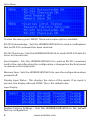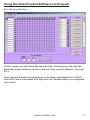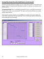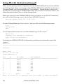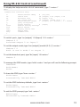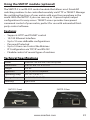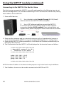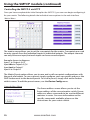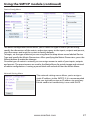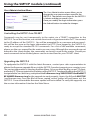
1
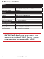
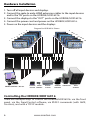
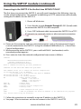
HDR8X8
HDR16X16
8/16-port HDMI Matrix Switch
with Front Panel, RS-232, IR, and TCP/IP Control
COMPLIANT
Installation
Manual
Made in the U.S.A.
www.smartavi.com
www.smartavi.com
1-800-AVI-21311
What’s in the Box?
PART NO.
QTY
DESCRIPTION
HDR8X8/HDR16X16
1
HDMI 8X8/16x16 Router
CCPWR06
1
6ft Power Cord
Table of Contents
INTRODUCTION & FEATURES
3
TECHNICAL SPECIFICATIONS
4
APPLICATIONS
5
HARDWARE INSTALLATION
6
USING THE FRONT PANEL CONTROL
7
USING THE SMARTCONTROL SOFTWARE
9
OPTIONAL CONTROL METHODS
15
USING THE IR REMOTE CONTROL (OPTIONAL)
16
USING RS-232 CONTROL (OPTIONAL)
17
USING THE SMTCP MODULE (OPTIONAL)
23
LIMITED WARRANTY STATEMENT
30
HDR 16X16 Front
HDR 16X16 Rear
2
www.smartavi.com
Introduction
The HDR8X8/HDR16X16 conforms to the HDMI (High Definition Media
Interface) standard with HDCP compliance and provides a connection
to view any eight/sixteen HDMI video sources on any combination
of eight/sixteen video displays. The matrix configuration provides
maximum flexibility, allowing switching between any high-definition
source and/or display. The HDR8X8/HDR16X16 provides HDMI output
up to 40 feet and at HDTV resolutions of 480p, 720p, 1080i and 1080p.
The system works with HD-DVD players, TiVo systems, HT PCs, and
satellite set-top boxes that connect to an HDMI display. Users can
switch to any source locally or remotely via Front Panel, RS-232, IR, or
TCP/IP connection. It is controlled by Windows®-based software that is
easy to understand and simple to use – a cornerstone of all SmartAVI
products.
Features
•
•
•
•
•
•
•
•
•
•
•
•
Switches 8/16 HDMI inputs with 8/16 HDMI outputs
Sources can be routed independently to displays
Switching controlled via the front panel, RS-232, IR and TCP/IP
Supports high definition video resolutions of 480p, 720p, 1080i and
1080p
Supports 7.1 Digital Surround Sound Audio
HDCP and HDMI 1.4 compliant
Supports EDID for total control of compliant displays
Learn EDID from any display
Delivers uncompressed digital video with zero signal loss
Outputs HDMI up to 40 feet (with high-quality 24AWG or better cable)
Rack-mountable
Front panel can be locked to prevent accidental changes
www.smartavi.com
3
Technical Specifications
VIDEO
HDTV Resolutions
TV Resolution
Input Interface
Output Interface
Input Cable Length
Output Cable Length
480p, 720p, 1080i, 1080p, Supports all DVI-D Resolutions
480i
(8/16) HDMI Type A 19-pin Female TMDS
(8/16) HDMI Type A 19-pin Female TMDS
Up to 40 ft.
Up to 40 ft.
OTHER
Warranty
Control
Power
Dimensions
Weight
HDR 16X16 Approvals
Power Supply Approvals
Limited 1 Year Parts and Labor
Panel, RS-232, IR, USB and TCP/IP
Internal 100-240 VAC
19”W x 5.25”H (2U) x 7”D
10 lbs.
FCC, CE, RoHS Compliant
UL, CE, CSA, CEC, RoHS
ENVIRONMENTAL
Operating Temperature
0 to +40° C (+32° to 104° F)
Operating Humidity
Storage Temperature
Storage Humidity
10% to 85% (Non-condensing)
-20° to +60° (+20° to +140° F)
10% to 85% (Non-condensing)
IMPORTANT: Each input and output can
support up to 10mA/5VDC. Do not connect
extenders that are powered by HDMI.
4
www.smartavi.com
Application Diagram
40 ft. over HDMI
40 ft. over HDMI
IR-EYE
SMTCP
SRC-2A
Rack Servers
Computer
Gaming
Console
HDMI INPUT
Blueray
Player
HDMI OUTPUT
Video
Camera
RS-232
Signage
Player
CAT5/6
IR
Control RS-232, USB
Control
TCP/IP
Control
INFRARED
Diagram for HDR 16X16 Shown
Applications
•
•
•
•
•
•
•
Corporate or Educational Presentations
Financial (Remote Servers/User Control)
Call Centers for Technical Support
Industrial (Long-Range Workstation Isolation)
Airport Installations (Air Traffic Control/Passenger Information)
KVM Extension where Exceptional Quality of Signal is Crucial
Medical (Remote Operation Away from Sensitive/Magnetic
Equipment)
• Recording (for Large Studios where Editing/Mixing Stations are
Compact and/or Require Complete Silence)
www.smartavi.com
5
Hardware Installation
1.Turn off all input devices and displays.
2.Connect the male to male HDMI extension cables to the input devices
and to the “IN” ports on the HDR8X8/HDR16X16.
3.Connect the displays to the “OUT” ports on the HDR8X8/HDR16X16.
4.Connect the power cord and power-on the HDR8X8/HDR16X16.
5.Power on the input devices and the displays.
Diagram for HDR16X16 Shown
1
2
3
4
6
5
7
9
8
DISPLAYS 1-8
1
2
3
4
SMARTCONTROL / RS-232
10
11
12
13
14
15
16
DISPLAYS 9-16
5
6
7
8
9
SIGNAGE VIDEO
PLAYER CAMERA
16
15
14
13
12
11
10
BLURAY
PLAYER
GAMING COMPUTER
CONSOLE
Controlling the HDR8X8/HDR16X16
RACK
SERVERS
There are multiple ways to control the HDR8X8/HDR16X16: via the front
panel, via the SmartControl software, via RS232 commands (with AMX,
Crestron), and with a TCP-IP module.
6
www.smartavi.com
Using the Front Panel Control
Front Panel Buttons
NOTE: To lock the front panel buttons to avoid any accidental
changes, press ESC + MENU + ENTER + SWITCH at the same
time. The display will indicate that it is locked. Repeat the
procedure to unlock the front panel.
During normal operation, you will see a list of ports on the front panel
display.
Default Display HDR16X16
To assign an output to an input, press SWITCH. A blinking block cursor
will appear. Use UP and DOWN to select the input that you would like to
assign. Once the cursor is over the desired input port, press ENTER to enter
editing mode. Press UP and DOWN to select the output port. Once you
have selected an output, press ENTER to save the configuration. To escape
from editing mode, press ESC.
IMPORTANT: Because HDCP takes time to negotiate, when switching ports,
wait 2 seconds for the process to complete. Failure to do so may cause an
error with the HDCP and the HDR8X8/HDR16X16 may lock up.
www.smartavi.com
7
Main Menu
To view the menu, press MENU. There are 6 menu options available:
RS-232 Acknowledge - Sets the HDR8X8/HDR16X16 to send a confirmation
that an RS-232 command has been received.
RS-232 Checksum - Sets the HDR8X8/HDR16X16 to verify all RS-232 data for
errors in transmission.
Send Update - Sets the HDR8X8/HDR16X16 to send an RS-232 command
back to the controller when the configuration is changed via the front panel
or remote control (optional).
Memory Save - Sets the HDR8X8/HDR16X16 to save the configuration when
powered off.
Display Input Status - This displays the status of the inputs. If no input is
present, the display will read NONE. This is the default view.
Input Display
Restore Factory Settings - Sets the HDR8X8/HDR16X16 to the default
factory configuration.
8
www.smartavi.com
Using the SmartControl Software
Find the Installation CD that came with your HDR8X8/HDR16X16 unit. This CD
has the SmartControlPro software that you will need in order to control the
unit using a computer.
Insert the CD into your CD-ROM. On the CD you should see:
• SmartControl Pro Installer.exe
• SmartControl Pro Help File
• HDR8X8/HDR16X16 Manual in PDF format
Double click SmartControlPro.exe in order to initiate software installation. Click
Install. After installation has completed, click CLOSE.
In order to use the software, click on the START
button>Programs>SmartControl Pro. There you should see a help file, the
SmartControl Pro launcher as well as a shortcut to uninstall SmartControl Pro.
Click on SmartControl Pro in order to launch the software.
When the software starts you will see a screen like this (HDR16X16 Shown):
HDR16X16
www.smartavi.com
9
Using the SmartControl Software (continued)
Advanced Configuration: will want to check this box.
If you have more than one Router installed you
Router Type: Select “HDR8X8/HDR16X16”
Inputs/Outputs: Enter the number of Inputs/Outputs your HDR8X8/
HDR8X8/HDR16X16 has. The HDR8X8/HDR16X16 can have up to 8/16 inputs
and 8/16 outputs.
Com Port: Select the appropriate com port that your computer is
using to access the router.
Router Time out: By default this is 0 meaning the computer
acknowledges commands almost instantly. Sometimes a computer takes
longer to respond. This setting should be left at 0. If you need to change it, it
should be no higher than 0.2.
After you have entered in the necessary information click OK. This will now
take you to the Main Routing Window where you can route the different video/
audio connections.
10
www.smartavi.com
Using the SmartControl Software (continued)
Main Routing Window
On this screen you will notice the input buttons running down the left side
while the output buttons run across the top. They are each labeled 1 through
8/16.
Note: The three small colored buttons at the lower right labeled ALL, VIDEO,
and AUDIO are not available if AV Split was not checked when you configured
your router.
www.smartavi.com
11
Using the SmartControl Software (continued)
The Main Routing Window enables you to control the router(s) connections by
means of the Crosspoint panel, the button panel, or with pre-recorded routes
called macros.
Crosspoint Panel: This is probably the simplest way to route the connections.
Simply click on the cross point itself. The input on the left will then be routed
to the output above.
Note: Inputs can be routed to several different outputs, but each output can
only have a single input at any one time. So you can have several connections
horizontally but not vertically.
12
www.smartavi.com
Using the SmartControl Software (continued)
The Button Panel:
These are the numbered buttons across the top and left sides. Click an output
button on the top, and then click an input button on the left.
Options for using the Button Panel
•
Output Options:
To select multiple outputs next to each other, click on one output, then
hold the shift key down and click the last output. When the input is
clicked, it is routed to all selected outputs.
To select multiple outputs individually, hold the control key down and
click on any number of outputs. When the input is clicked, it is routed to
all selected outputs.
•
Input Options:
To route an input to all the outputs at once, hold the control key down
and click on an input.
To leave the outputs selected after the route is made, hold the shift key
down and click on an input.
www.smartavi.com
13
Using the SmartControl Software (continued)
Macros: This section of the window is used to save and play back macros.
Macros store a set sequence of routes.
To record a macro:
1. Click on the Record button (last button shown). A blinking “recording”
message below this button will be displayed to indicate that all routes are
being recorded.
2. Select the desired crosspoints. There is no limit on the number of routes
you may record.
3. If you click a macro button while in the record mode, the macro will be
executed, and these routes will be added to the recording. This makes it
possible to combine the routes of two or more macros into one bigger
macro.
4. When finished, click the “Save Macro” button. You will be instructed to then
click on one of the macro buttons. Doing this will save the recorded routes
to that button.
To cancel saving the macro, click the “Cancel Save” button.
5. To play back a macro, simply click on one of the 50 macro buttons. Use the
scroll bar to bring any of these into view.
6. The macros are automatically saved in the current configuration file. They
are also saved when you select the File/Save Configuration... menu.
To save macros in a separate file for a special purpose, select the File/Save
Macros...menu.
14
www.smartavi.com
Optional Control Methods
IR: Many system professionals prefer the IR control interface because it
offers greater flexibility to manage the HDR8X8/HDR16X16 at a distance.
In some cases, the displays will not be visible from the matrix. In these
situations it is necessary to control the matrix with Infrared control.
RS-232: Controlling the HDR8X8/HDR16X16 has never been simpler
with SmartControl software. With SmartControl, you can assign a unique
name to each port on the HDR8X8/HDR16X16, as well as each display,
customizing projects to meet your needs. Although all the functions of the
matrix are available locally on the front panel of the HDR8X8/HDR16X16,
using SmartControl allows for customization of all the matrix functions.
TCPIP (SMTCP): Remote control is essential to real-time management of
the HDR8X8/HDR16X16. SmartAVI’s SMTCP module is the perfect solution
to effective remote management. Simply connect the SMTCP module
to the HDR8X8/HDR16X16 and connect from anywhere on the internet.
When you need to make a change, but can’t be there in person, the SMTCP
makes remote control a snap.
www.smartavi.com
15
Using the IR Remote Control (optional)
You have the option of controlling the HDR8X8/HDR16X16 via Remote Control. The remote is used to control the HDR8X8/HDR16X16. The SM-EYE must
be connected to the HDR8X8/HDR16X16 ( this is an optional connector not
always available in all boxes) in order to interface the remote control with the
matrix. The way the remote control the matrix is as follows:
Xx<enter>yy<enter>
When XX is the output , YY is the input
To change the routing of the signals,
For example, to set output 3 to input 2 press “0” + “3” + ENTER, then press “0” +
“2” + ENTER. If a wrong button is pressed, the user must either press the ESC
button or wait 5 seconds before restarting the sequence.
16
www.smartavi.com
Using RS-232 Control (optional)
How to properly create an RS-232 connection between a PC and most SmartAVI
RS-232 compliant devices
Establish a connection to your RS232 compliant device:
1. Connect a straight through male
to female RS-232 cable (shown on
right) to the RS-232 connector on
the PC.
2. Connect the other end of the cable
to the RS-232 compliant device.
3. Power on the device.
Male to Female Straight Cable (not provided)
Setting up the Terminal
application:
1. Open Hyperterminal on the PC. (or
use the terminal client of your choice)
2. Use the default settings to create a
connection to the device (see settings
on left). Settings MUST match those
shown on the lower right.
3. Be sure that Flow Control is None.
4. The output of the device will be the
same as the PC.
Hyperterminal Settings
www.smartavi.com
17
Using RS-232 Control (continued)
There are two primary modes of operation for the HDR8X8/HDR16X16: Command Mode
and Debug Mode. When connecting to the HDR8X8/HDR16X16 via RS-232, it will start in
Command Mode (see Command Mode p. 19 for options). Debug Mode is a more userfriendly way of operating the HDR8X8/HDR16X16 and includes instructional menus. The
following section details the use of the Debug Mode.
When you connect to the HDR8X8/HDR16X16 to a computer via an RS-232 connection,
you will see the following screen (results from HDR16X16 shown):
SmartAVI HDMI 16X16 ver 12.06.11#1
To enter Debug Mode type “d on <enter>” and you will see the following prompt:
d on
Debug mode:
DBG>
To exit Debug Mode (and enter Command Mode) type “d off <enter>”
DBG>d off
Command line debugging disabled.
Type “d on” to re-enable.
To display the HDR8X8/HDR16X16 information including crosspoint data, type “info
<enter>”
DBG>info
===============================================================
SmartAVI
HDMI 16X16
fw ver. 12.06.11#1
Frame Address: 0
OUT
IN
IN STATE
OUT_ENABLED
===============================================================
1
1
HDMI*
YES
2
1
HDMI*
YES
3
1
HDMI*
YES
4
1
HDMI*
YES
5
1
HDMI*
YES
6
1
HDMI*
YES
7
1
HDMI*
YES
8
1
HDMI*
YES
...
16
1
HDMI*
YES
Note: an asterisk (*) denotes that the signal is HDCP encrypted.
18
www.smartavi.com
Using RS-232 Control (continued)
To display the help menu for a list of commands, type “? <enter>”
DBG>?
===========================================================================
Command Line Interface Help:
d
Enable/Disable debug
d [on][off]
sw
Switch Port
sw [output] 1-16 [input] 1-16
br
Broadcast Port
br [input] 1-16
om
Set output mode
om [output] [mode# (0-2) | ?]
o
Enable/Disable Output
o [output] [0 = disable | 1 = enable
q
Query Crosspoints
h
Toggle Hotplug
h [input]
reset
Restore Factory Settings
boot
Reboot matrix
info
Display matrix info
edid
Manage EDID
help
Command list
?
===========================================================================
To switch ports, type “sw [output] 1-16[input] 1-16 <enter>”
DBG>sw 2 2
Switched Output 2 to Input 2
To set the output mode, type “om [output] [mode# (0-2) | ?] <enter>”
DBG>om 1 0
HDCP is now in mode 0 on output 1.
To set the broadcast port, type “br [input] 1-8<enter>”
DBG>br 2
To manage the EDID modes, type “edid <enter>” and you will see the following prompt:
DBG>edid
EDID Mode:
EDID>
To learn the EDID, type “learn <enter>”
EDID>learn
Successfully learned EDID!
To set the EDID to factory defaults, type “savi <enter>”
EDID>learn
Successfully learned EDID!
To exit the EDID prompt, type “exit <enter>”
EDID>learn
Successfully learned EDID!
www.smartavi.com
19
Using RS-232 Control (continued)
Command Mode: Command Mode allows raw commands to be sent to the HDR8X8/
HDR16X16 to control its various functions without the use of a menu or prompt. This
mode is intended for advanced use only.
There are two types of commands that you can issue the HDR8X8/HDR16X16:
Commands with CHECKSUM and Commands without CHECKSUM. The CHECKSUM is a
method of error correction that ensures the command has been properly transmitted to
the HDR8X8/HDR16X16. However, it is not necessary to perform the CHECKSUM in most
cases.
Commands with CHECKSUM begin with //
Commands without CHECKSUM begin with \\
Sending Commands WITH CHECKSUM
Comm Port Settings:
Baud Rate 9600
Start Bits 1
Data Bits 8
Parity None
Stop Bits 1
1) To set a video crosspoint:
//FxxMyyIzz<CHK><CR>
e.g. to set video input 3 to output 12 on a router with frame address “0”
send the command: //F00M12I03<0x42><CR>
2) To set RS-232 crosspoint:
//FxxRyyIzz<CHK><CR>
3) To disconnect RS-232 crosspoint:
//FxxDyyIzz<CHK><CR>
4) To set new frame address:
//FxxFnn<CHK><CR>
20
www.smartavi.com
Using RS-232 Control (continued)
Command Mode continued:
5) To query crosspoints from PC:
//FxxU<CHK><CR>
• If all outputs are connected to input 1 then a 4x4 Matrix will respond
with <0x80><0x80><0x80><0x80><CR>
• The router will send back one byte for each output and the string
ends with a <CR>. The first byte sent is Output #1. In the example
above, since there are 5 bytes total, we know that there are 4
outputs.
• To calculate the input number, the router sends the input number
with the 7th bit set.
0x80 = “1000 0000” input 0
0x81 = “1000 0001” input 1
…
0x8F “1000 1111” input 15
Notes:
When successful, commands #1-4 will acknowledge by sending the
checksum with nibbles swapped & <CR><LF>
e.g. checksum of 0x24 acknowledges with <0x42><CR><LF>
IMPORTANT
CALCULATING THE <CHK>
<CHK> stands for CHECKSUM: the <CHK> value is
calculated by performing an XOR of the full command string. For example: //F00M12I03 will XOR
to the hexadecimal value 0x42, therefore the value
of <CHK> is 0x42.
www.smartavi.com
21
Using RS-232 Control (continued)
Command Mode continued:
Sending Commands WITHOUT CHECKSUM
1) To set a video crosspoint:
\\FxxMyyIzz<CR>
e.g. to set video input 3 to output 12 on a router with frame address “0”
send the command: \\F00M12I03<CR>
2) To set RS-232 crosspoint:
\\FxxRyyIzz<CR>
3) To disconnect RS-232 crosspoint:
\\FxxDyyIzz<CR>
4) To set new frame address:
\\FxxFnn<CR>
5) To query crosspoints from PC:
\\FxxU<CR>
• If all outputs are connected to input 1 then a 4x4 Matrix will respond
with <0x80><0x80><0x80><0x80><CR>
• The router will send back one byte for each output and the string
ends with a <CR>. The first byte sent is Output #1. In the example
above, since there are 5 bytes total, we know that there are 4
outputs.
• To calculate the input number, the router sends the input number
with the 7th bit set.
0x80 = “1000 0000” input 0
0x81 = “1000 0001” input 1
…
0x8F = “1000 1111” input 15
22
www.smartavi.com
Using the SMTCP module (optional)
The SMTCP-2 is an RS-232 control module that allows most SmartAVI
switching matrixes to be controlled remotely via HTTP or TELNET. Manage
the switching functions of your matrix with ease from anywhere in the
world. With the SMTCP-2 you can save up to 10 preset input/output
configurations for easy access. TELNET access provides transparent
command control of your matrix, perfect for use with automated thirdparty control software.
Features
•
•
•
•
•
•
•
Supports HTTP and TELNET control
10/100 Ethernet Interface
Up to 10 user-definable configurations
Password Protected
Up to 5 Users can Control the Matrixes
IP Configuration via TCP/IP and RS-232
Flexible control of several types of matrixes
Technical Specifications
Power
External 100-240 VAC/5VDC2A @10W
Dimensions
2.8125”W x 1”H x 3.375”D
Weight
0.5 lbs
Approvals
UL, CE, ROHS Compliant
Operating Temp.
32-131°F (0-55 °C)
Storage Temp.
-4-185 °F (-20-85 °C)
Humidity
Up to 95%
SMTCP-2 Front
SMTCP-2 Rear
www.smartavi.com
23
Using the SMTCP module (continued)
Connecting to the SMTCP-2 for the first time
The first time you connect the SMTCP-2, you will need to perform the following steps to set
the initial configuration. This includes establishing an HTTP connection and manually setting
the IP address for the SMTCP-2.
1. Power off all devices.
2. Use a female to male Straight-Through RS-232 (Serial)
cable to connect the SMTCP-2 to the computer.
3. Use a CAT5 ethernet cable to connect the SMTCP-2
to a TCP/IP network via a network router or other network
connection that has DHCP enabled. If your network does not
support DHCP, please see page 22 of this manual for instructions.
RS-232
SERIAL
CAT5
CAT5
COMPUTER
IP ROUTER
SMTCP-2
MATRIX SWITCH (NOT CONNECTED)
4. Power on the computer and run a terminal program such as Hyperterminal to open a
serial connection to the SMTCP-2 using the standard 9600 baud, 8, N, 1 configuration.
5. Power on the SMTCP-2. When powered on, it will obtain an IP address automatically via
DHCP from the network.
6. The IP information for the SMTCP-2 will be displayed on the terminal screen as follows:
**************************
* SmartAVI control is UP *
*
version 10.12.20#6
*
**************************
addr:192.168.1.102
Mask:255.255.255.0
gtwy:192.168.1.1
**************************
NOTE: the above IP address is for demonstration purposes only. Actual results may be different.
7. The IP address shown must be used to connect to the SMTCP via HTTP.
24
www.smartavi.com
Using the SMTCP module (continued)
8. Open a web browser and navigate to the IP address
that is indicated. You will be prompted to enter a
username and password.
9. The default login (case sensitive) is as follows:
User ID: Admin
Password: Pass
10. Once connected to the SMTCP-2, you will see the following menu of options:
1. Matrix
2. Frame Address
3. Device Config
4. Network Setting
5. User Administration
For the initial setup, click the Network Setting button and
manually assign an IP address to the SMTCP-2. This will assure
that the SMTCP-2 will always have the same IP address. Be
sure to choose an address that will not conflict with any other
devices on the network, and that the address is not in the
range of the DHCP server.
11. Once you have manually
assigned an IP address to the SMTCP-2, you may disconnect the
Straight-Through RS-232 (Serial) cable from the computer
12. Connect the SMTCP-2 to the matrix switch with a Cross RS232 (Serial) cable.
CAT5
RS-232
SERIAL
CAT5
COMPUTER
IP ROUTER
SMTCP-2
MATRIX SWITCH
It is also recommended that you set a password for the SMTCP-2 at this point. To set the password (and/or username), click on the User Administration button, enter the password and
click Submit. This sets the password for the HTTP interface only.
www.smartavi.com
25
Using the SMTCP module (continued)
Controlling the SMTCP-2 via HTTP
Once you have completed the Initial Setup for the SMTCP-2, you can now begin configuring it
for your matrix. The following details the individual menu options in the web interface:
Matrix Menu
The matrix menu allows you to set the crosspoints for the matrix. Crosspoints are used
to route signals from the individual inputs to individual outputs. The output channels
can only have one input, but each input can have several outputs.
Example shown in diagram:
Input 1 to Outputs 3,4,5
Input this to Outputs 6,7,8
Input test to Output 1
Input 6 to Output 2
The Matrix Preset option allows you to save and recall crosspoint configurations with
the push of a button. To save a preset, simply configure your crosspoints and press the
SAVE button next to the desired preset. To recall a preset, simply click on the button
with its name. To edit the preset names, see the Device Config menu.
Frame Address Menu
The frame address menu allows you to set the
frame address of the current matrix switch. Frame
addresses allow commands to be sent to different
matrixes in series. For more information on the
specific commands available, please see the
instructions for your matrix switch.
26
www.smartavi.com
Using the SMTCP module (continued)
Device Config Menu
The device configuration menu allows you to select the type of matrix you are using,
specify the dimensions of the matrix, and assign names to the inputs, outputs and presets,
reset the names and reset the system to factory defaults.
To begin, set the type of device you are using from the drop-down menu labeled Device
Type and specify the Matrix Dimensions. After specifying the Matrix Dimensions, press the
Submit button to make the changes.
Once the type of matrix is entered, you can assign names to each of your inputs, outputs
and presets. The preset names are used in the Matrix Menu for quick storage and retrieval
of matrix configurations. Leaving a preset blank will exclude it from the Matrix Menu.
Network Setting Menu
The network setting menu allows you to assign a
static IP address to the SMTCP-2. It is recommended
that you statically assign an IP address to avoid any
future conflict or connectivity issues with DHCP.
www.smartavi.com
27
Using the SMTCP module (continued)
User Administration Menu
The User Administration menu allows you to
change the user name and password for the
SMTCP-2. The default user name for the SMTCP-2
is Admin and the password is Pass.
Once you modify the login information, press
the Submit button to make the changes.
Controlling the SMTCP-2 via TELNET
Commands may be sent transparently to the matrix via a TELNET connection to the
SMTCP-2. To use this function, use a telnet client such as Hyperterminal or PuTTY to connect
to the IP address of the SMTCP-2. You will be prompted for a username and password this will be the same as the login information via HTTP. Once logged in, the SMTCP-2 is
ready to accept the standard RS-232 commands. For a list of the available commands,
please see the user manual for the matrix you are using. Although the commands are not
echoed to the client display, the commands are being issued to the matrix. Should you
need commands to be echoed, please see the instructions for your TELNET client.
Upgrading the SMTCP-2
To updgrade the SMTCP-2 with the latest firmware, contact your sales representative to
obtain the firmware upgrade file or visit the SMTCP-2 product page at www.smartavi.com.
The version information is listed on the Main Menu. Once you have the file, use an FTP client,
preferablyTFTP, to navigate to the IP address of the SMTCP-2.To upload the file to the SMTCP-2,
navigate to the /var/ directory, and upload the file firmware.img - IMPORTANT: the file MUST
BE NAMED firmware.img for the upgrade to work properly. Again, the full path MUST BE
/var/firmware.img. Once the file has been copied, restart (power off and power on) the
SMTCP-2. Once restarted the firmware update will be installed. To verify the upgrade, see
the version information listed on the Main Menu.
28
www.smartavi.com
Using the SMTCP module (continued)
Connecting to the SMTCP-2 for the first time WITHOUT DHCP
The first time you connect the SMTCP-2, you will need to perform the following steps to
set the initial configuration. This includes establishing an HTTP connection and manually
setting the IP address for the SMTCP-2.
1. Power off all devices.
2. Use a female to male Straight-Through RS-232 (Serial) cable
to connect the SMTCP-2 to the computer.
3. Use a CAT5 ethernet cable to connect the SMTCP-2 to a TCP/
IP network via a network router or other network connection.
RS-232
SERIAL
CAT5
CAT5
COMPUTER
IP ROUTER
SMTCP-2
MATRIX SWITCH (NOT CONNECTED)
4. Power on the computer and run a terminal program such as Hyperterminal to open
a serial connection to the SMTCP-2 using the standard 9600 baud, 8, N, 1, None Flow
Control configuration.
5. While powering on the SMTCP-2, press and hold Shift-1 (exclamation) until a
command prompt appears.
6. Press enter to show the network configuration help screen as follows:
Command:
ÉÍÍÍÍÍÍÍÍÍÍÍÍÍÍÍÍÍÍÍÍÍÍÍÍÍÍÍÍ»
º Network Configuration help º
ÈÍÍÍÍÍÍÍÍÍÍÍÍÍÍÍÍÍÍÍÍÍÍÍÍÍÍÍͼ
Enter a command followed by optional parameters
Commands are SET DHCP INFO RESET and QUIT/SAVE
SET command allows you to change the network configuration:
SI xxx.xxx.xxx.xxx = Set IP Address
(if IP address is not entered then DHCP is ENABLED)
SM xxx.xxx.xxx.xxx = Set IP Mask
SG xxx.xxx.xxx.xxx = Set Gateway Address
RN
= Reset Network Params:
IPADDR = 192.168.0.2
IPMASK = 255.255.255.0
GATEWAY = 192.168.0.1
DHCP ON
= Enable DHCP
DHCP OFF
= Disable DHCP
INFO
= Display network configuration
RESET
= Factory reset
QUIT
= Saves configuration and quits
SAVE
= Same as QUITNOTE: the above IP address is for demonstration purposes
only. Actual results may be different.
7. Follow the instuctions to manually assign an IP address to the SMTCP-2.
8. See page 19 for instructions on how to connect to the SMTCP-2 via HTTP.
www.smartavi.com
29
Limited Warranty Statement
A. Extent of limited warranty
1. SmartAVI Technologies, Inc. warrants to the end-user customers that the SmartAVI
product specified above will be free from defects in materials and workmanship for the
duration of 1 year, which duration begins on the date of purchase by the customer.
Customer is responsible for maintaining proof of date of purchase.
2. SmartAVI limited warranty covers only those defects which arise as a result of normal
use of the product, and do not apply to any:
a. Improper or inadequate maintenance or modifications
b. Operations outside product specifications
c. Mechanical abuse and exposure to severe conditions
3.
If SmartAVI receives, during applicable warranty period, a notice of defect, SmartAVI
will at its discretion replace or repair defective product . If SmartAVI is unable
to replace or repair defective product covered by the SmartAVI warranty within
reasonable period of time, SmartAVI shall refund the cost of the product.
4.
SmartAVI shall have no obligation to repair, replace or refund unit until customer
returns defective product to SmartAVI.
5.
Any replacement product could be new or like new, provided that it has functionality
at least equal to that of the product being replaced.
6. SmartAVI limited warranty is valid in any country where the covered product is
distributed by SmartAVI.
B. Limitations of warranty
TO THE EXTENT ALLOWED BY LOCAL LAW , NEITHER SMARTAVI NOR ITS THIRD PARTY SUPPLIERS
MAKE ANY OTHER WARRANTY OR CONDITION OF ANY KIND WHETHER EXPRESSED OR IMPLIED ,
WITH RESPECT TO THE SMARTAVI PRODUCT , AND SPECIFICALLY DISCLAIM IMPLIED WARRANTIES
OR CONDITIONS OF MERCHANTABILITY, SATISFACTORY QUALITY , AND FITNESS FOR A PARTICULAR
PURPOSE
C. Limitations of liability
To the extent allowed by local law the remedies provided in this warranty statement are the customers
sole and exclusive remedies
TO THE EXTENT ALLOWED BY LOCAL LAW , EXCEPT FOR THE OBLIGATIONS SPECIFICALLY SET FORTH
IN THIS WARRANTY STATEMENT , IN NO EVENT WILL SMARTAVI OR ITS THIRD PARTY SUPPLIERS BE
LIABLE FOR DIRECT, INDIRECT, SPECIAL, INCIDENTAL, OR CONSEQUENTIAL DAMAGES WHETHER BASED
ON CONTRACT , TORT OR ANY OTHER LEGAL THEORY AND WHETHER ADVISED OF THE POSSIBILITY
OF SUCH DAMAGES.
D. Local law
To the extent that this warranty statement is inconsistent with local law, this warranty statement
shall be considered modified to be consistent with such law.
30
www.smartavi.com
© Copyright 2012 SmartAVI, All Rights Reserved
NOTICE
The information contained in this document is subject to
change without notice. SmartAVI makes no warranty of any
kind with regard to this material, including but not limited
to, implied warranties of merchantability and fitness for
any particular purpose.
SmartAVI will not be liable for errors contained herein or
for incidental or consequential damages in connection
with the furnishing, performance or use of this material.
No part of this document may be photocopied, reproduced
or translated into another language without prior written
consent from SmartAVI.
For more information, visit www.smartavi.com.
SmartAVI, Inc. / Twitter: smartavi
11651 Vanowen St. North Hollywood, CA 91605
Tel: (818) 503-6200 Fax: (818) 503-6208
http://www.SmartAVI.com
www.smartavi.com
31
At SmartAVI, we offer a complete line of audio video solutions for high-quality
signal switching and distribution. Our devices support multiple signal types
including VGA, DVI, HDMI, USB, RS232, IR and more.
HDMI SOLUTIONS
HDMI EXTENDERS
At SmartAVI, we offer a complete line of HDMI solutions
for high-quality HDMI signal switching and distribution.
Our HDMI devices support all of your HDTV’s, DVR’s,
DVD Players, Blue-ray players, video game consoles,
computers and many other HDMI compliant devices.
CAT5/5e/6 UTP/STP
HDMI COMPUTER
HD DISPLAY
HDMI EXTENDERS
Extend HDMI up to 330 feet away over CAT5/5e/6 UTP/STP cable.
HDMI MATRIXES
HDX-100
Extend HDMI up to 150 feet away with local
monitor.
DVR
HDX-1000
Extend HDMI with IR control up to 200 feet
away.
HDMI MATRIX SWITCH
HD DISPLAYS
GAMING CONSOLE
The rack-mountable HDR
series of HDMI switching
matrixes, available in 4X4,
8X8, 16X16 and 32X32,
provide HDMI switching up to
40 feet. You can switch to any source locally
or remotely via a RS-232, IR or TCP/IP connection.
HDX-Ultra
Extend HDMI, IR and RS-232 up to 330 feet
away.
FX-HDPRO Extend HDMI, IR, and RS-232
signals 1,200 feet over fiber optic cable.
HDR4X4 Switch HDMI 1080p and digital audio from any 4
HDMI sources to 4 remote HD displays.
HDR8X8 Switch HDMI 1080p and digital audio from any 8
HDMI sources to 8 remote HD displays.
HDR16X16 Switch HDMI 1080p and digital audio from any 16
HDMI sources to 16 remote HD displays.
HDMI SWITCHES
DVR
HDR32X32 Switch HDMI 1080p and digital audio from any 32
HDMI sources to 32 remote HD displays.
HDMI MATRIX SWITCH
HD DISPLAY
GAMING CONSOLE
At SmartAVI, we offer high-quality products including digital
signage, video wall, signal extenders, splitters and switches,
and fiber optics. All of our products are manufactured in
the United States in our North Hollywood, California facility.
The HR series of HDMI switches provide HDMI output up to 40
feet and at HDTV resolutions of 480p, 720p, 1080i and 1080p.
HR-2P HDMI SWITCH
Switch two HDMI sources on one display.
HR-4P HDMI SWITCH
Switch four HDMI sources on one display.
SmartAVI, Inc. / Twitter: smartavi - 11651 Vanowen St. North Hollywood, CA 91605
Tel: (818) 503-6200 Fax: (818) 574-5581 - http://www.SmartAVI.com
32
Made in the U.S.A.
www.smartavi.com
www.smartavi.com
S M A R T A U D I O V I D E O I N N O V AT I O N
1-800-AVI-2131