1
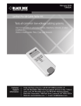
1 LANtest Kit Operations Manual For 256551 LANtest Kit™ Hobbes GmbH Jacobsenweg 1 22525 Hamburg Germany 1 LANtest Kit CONTENTS INTRODUCTION................................................................................................................ 2 FEATURES ........................................................................................................................... 2 PACKAGE CONTENTS ..................................................................................................... 2 PRODUCT PROFILE.......................................................................................................... 3 I. Loopback Test .......................................................................................................... 3 1. 10Base-T Test .......................................................................................................... 3 OPERATION ........................................................................................................................ 3 2. RJ11 Modular Cable Test..................................................................................... 3 3. Coaxial Cable Test ................................................................................................. 3 II. Remote Test ................................................................................................................ 4 Test Results ................................................................................................................... 4 2 LANtest Kit INTRODUCTION The LANTEST KIT Network Cable Tester is an innovative, practical tester that can easily read the correct pin configuration of 10BASE-T, 10BASE-2, RJ45/RJ11 modular, 258A, TIA-568A/568B and Token Ring cables by comparing one transmitting end to the corresponding receiving end. The included remote terminator allows the user to test installed cable either at a wall jack or a patch panel. Verifying continuity and testing for faults such as open, shorted and crossed pairs has never been easier and more affordable. FEATURES * Displays the actual pin configuration of 10BASE-T and 10BASE-2 Ethernet, RJ45/RJ11 modular, 258A, TIA-568A/568B and Token Ring cables * Provides easy to read continuity and fault status display * Checks for continuity, open wire, shorted pair and crossed pair faults * Allows for remote testing of installed cables from wall jack or patch panel * Tests shield wire integrity * Auto or manual scanning PACKAGE CONTENTS 1. LANTEST KIT Master Unit 2. LANTEST KIT Remote Unit 3. RJ45 Male to BNC Male Adapter Cable (Qty. 2) 4. RJ45 UTP Patch Cable 5. BNC Female/Female Coupler 6. RJ45/RJ11 Jack Size Adapter (Qty. 2) 1. RJ45 JACK 2. RJ45 JACK 3. LED DISPLAY FOR SOURCING END (JACK 1) 4. LED DISPLAY FOR RECEIVING END (JACK 2) 5. POWER SWITCH 6. LED SCANNING MODE SWITCH 7. TEST SWITCH FOR MANUAL SCAN 8. RJ45 JACK 9. LED DISPLAY FOR RECEIVING END (SAME AS JACK 2) 10. GROUND LED FOR RECEIVING END 11. BATTERY COMPARTMENT (9V) 3 LANtest Kit PRODUCT PROFILE I. Loopback Test 1. 10Base-T Test 1.1 1.2 1.3 1.4 1.5 Plug one end of the tested cable into the transmitting RJ45 jack on the master unit marked with a ' ' and the other end of the cable into the remaining receiving RJ45 jack. Slide power switch on. The upper row of LEDs will start to scan in sequence if the Auto/Manual button is set on "Auto" mode. The LED for pin 1 will light up if the button is in "Manual" mode. Switch back and forth from Auto or Manual scanning mode by pressing the Auto/Manual button on the side of the master testing unit. Once both ends of the cable are plugged in properly, the second row of LEDs will illuminate according to the corresponding LEDs in the top row. Read the results of the LED display for the pin configuration status of the tested cable. If you fail to read the results the first time in Auto mode, you may wait for the second LED scan, or simply switch to Manual mode for pin by pin testing. In Manual mode, pressing the square "Test" button will advance testing to the next pin. OPERATION Note: Make sure the battery power is sufficient. Insufficient battery power will lead to dimmed LEDs and incorrect results. 2. RJ11 Modular Cable Test 2.1 Please follow directions for the UTP/STP Cable Test and use the operations manual for the correct LED pin out display 3. Coaxial Cable Test 3.1 Plug the two attached BNC adapter cables on both RJ45 jacks. Then connect the tested cable to each end of the BNC adapter cables 4 LANtest Kit 3.2 For the remaining testing procedures, please refer to steps 1.2 to 1.5 Note: 1. The center pin of BNC should be read on LED 2. 2. As Coaxial cable has only two wires, we suggest you read the result of the LED scan using Manual mode. II. Remote Test 1. Plug one end of the tested cable to the transmitting RJ45 jack on the master unit marked with a ' ' and plug the other end into the remote terminator. If the tested cable is installed in a patch panel or wall plate, you may use the included patch cable to solve the connector gender problem. 2. Now, set the Auto/Manual switch to Auto mode for one-person testing. 3. Read the test results from the LED display on remote terminator. Note: The LED display on the remote unit will scan in sequence corresponding to the transmitting end of the master unit. Remote Test Sample Test Results 12345678G 1.Continuity: Pin 2 has continuity 12345678G 2.Open: Pin 2 is opened 12345678G 3.Short: Pin 2 and Pin 3 are shorted 12345678G 4.Miswire: Pin 3 and Pin 6 are miswired Caution: 1. Operating the tester in live circuits may damage the tester 2. Leaving the battery in the tester for long periods of time without use could drain power from the battery