1
NetExtreme II
Family Adapters
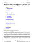
AT-2973SX
AT-2973T
AT-2973T/4
Installation and User’s Guide
613-001252 Rev. B
Copyright © 2011 Allied Telesis, Inc.
All rights reserved. No part of this publication may be reproduced without prior written permission from Allied Telesis, Inc.
Broadcom® and the pulse logo are among the trademarks of Broadcom Corporation. All other product names, company names,
logos or other designations mentioned herein are trademarks or registered trademarks of their respective owners.
Electrical Safety and Emissions Standards
This product meets the following standards.
Federal Communications Commission Interference Statement
Declaration of Conformity
Manufacturer Name: Allied Telesis, Inc.
Declares that the product: NetExtreme II Family Adapters
Model Numbers: AT-2973SX, AT-2973T, AT-2973T/4
This equipment has been tested and found to comply with the limits for a Class B digital device, pursuant to Part 15 of
FCC Rules. These limits are designed to provide reasonable protection against harmful interference in a residential
installation. This equipment generates, uses and can radiate radio frequency energy and, if not installed and used in
accordance with the instructions, may cause harmful interference to radio or television reception. However, there is no
guarantee that interference will not occur in a particular installation. If this equipment does cause harmful interference to
radio or television reception, which can be determined by turning the equipment off and on, the user is encouraged to try
to correct the interference by one of the following measures:
-
Reorient or relocate the receiving antenna.
-
Increase the separation between the equipment and the receiver.
-
Connect the equipment into an outlet on a circuit different from that to which the receiver is connected.
-
Consult the dealer or an experienced radio/TV technician for help.
This device complies with part 15 of the FCC Rules. Operation is subject to the following two conditions:
(1) This device must not cause harmful interference, and
(2) this device must accept any interference received, including interference that may cause undesired operation.
FCC Caution: Any changes or modifications not expressly approved by the party responsible for compliance could void
the user’s authority to operate this equipment.
IMPORTANT NOTE:
FCC Radiation Exposure Statement:
This equipment complies with FCC radiation exposure limits set forth for an uncontrolled environment. End users must
follow the specific operating instructions for satisfying RF exposure compliance.
This transmitter must not be co-located or operating in conjunction with any other antenna or transmitter.
IEEE802.11b or 802.11g operation of this product in the U.S.A. is firmware-limited to channels 1 through 11.
Industry Canada
This Class A digital apparatus complies with Canadian ICES-003.
Cet appareil numérique de la classe A est conforme à la norme NMB-003 du Canada.
European Union Restriction of the Use of Certain Hazardous Substances
(RoHS) in Electrical and Electronic Equipment
This Allied Telesis RoHS-compliant product conforms to the European Union Restriction of the Use of Certain Hazardous
Substances (RoHS) in Electrical and Electronic Equipment. Allied Telesis ensures RoHS conformance by requiring
supplier Declarations of Conformity, monitoring incoming materials, and maintaining manufacturing process controls.
3
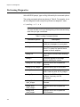
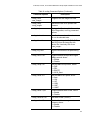
RFI Emissions
FCC Class B, EN55022 Class B, VCCI Class B, C-TICK, CE
Immunity
EN55024
Electrical Safety
EN60950-1 (TUV), UL 60950-1 (CULUS)
Laser Safety
EN60825
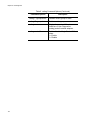
Translated Safety Statements
Important: The indicates that a translation of the safety statement is available in a PDF
document titled “Translated Safety Statements” on the Allied Telesis website at
www.alliedtelesis.com/support/software. After you have accessed this website, enter the model
number in the Search by Product Name box and then click Find to view the current list of
documents.
4
Contents
Preface ............................................................................................................................................................ 11
Safety Symbols Used in this Document ..................................................................................................... 12
Where to Find Web-based Guides............................................................................................................. 13
Contacting Allied Telesis............................................................................................................................ 14
Online Support..................................................................................................................................... 14
Email and Telephone Support ............................................................................................................. 14
Returning Products.............................................................................................................................. 14
For Sales or Corporate Information ..................................................................................................... 14
Warranty .............................................................................................................................................. 14
Management Software Updates .......................................................................................................... 14
Chapter 1: Introducing the AT-2973SX, AT-2973T, and AT-2973T/4 Adapters ............................................. 15
Functional Descriptions.............................................................................................................................. 16
AT-2973SX Adapter ............................................................................................................................ 17
AT-2973T Adapter ............................................................................................................................... 18
AT-2973T/4 Adapter ............................................................................................................................ 20
Features ..................................................................................................................................................... 22
TCP Offload Engine (TOE).................................................................................................................. 23
Internet Small Computer Systems Interface (iSCSI) ........................................................................... 24
Power Management ............................................................................................................................ 24
Wake on LAN (WOL) Feature ............................................................................................................. 24
Adaptive Interrupt Frequency .............................................................................................................. 25
ASIC with Embedded RISC Processor................................................................................................ 25
Supported Operating Environments .................................................................................................... 25
Chapter 2: Installing the Hardware ................................................................................................................. 27
Reviewing the Contents of Your Shipment ................................................................................................ 28
Reviewing Safety Precautions ................................................................................................................... 29
Pre-Installation Checklist............................................................................................................................ 31
Replacing the Bracket ................................................................................................................................ 32
Installing a Network Adapter Card ............................................................................................................. 34
Connecting the Network Cables................................................................................................................. 38
Chapter 3: Installing Broadcom Boot Agent Driver Software .......................................................................... 41
Overview .................................................................................................................................................... 42
Setting Up MBA in a Client Environment ................................................................................................... 43
Enabling the MBA Driver ..................................................................................................................... 43
Configuring the MBA Driver ................................................................................................................. 43
Setting Up the BIOS ............................................................................................................................ 44
Setting Up MBA in a Server Environment: Red Hat Linux PXE Server ..................................................... 45
Chapter 4: Installing the Monolithic Software Driver ....................................................................................... 47
Using the NetXtreme II Monolithic Driver ................................................................................................... 48
Inserting the NetXtreme II Monolithic Driver in a WinPE 2.0 Image........................................................... 50
Configuring the Speed and Duplex Settings .............................................................................................. 52
Chapter 5: Installing the NDIS2 Driver Software ............................................................................................ 55
Overview .................................................................................................................................................... 56
5
Contents
Checking Pre-installation Requirements .................................................................................................... 57
Installing the NDIS2 Driver Software on MS-DOS Platforms ..................................................................... 58
Creating a Startup Disk ........................................................................................................................ 58
Modifying the Startup Disk ................................................................................................................... 59
Installing the DOS NDIS2 Driver Software........................................................................................... 61
Using Keywords for the Drivers .................................................................................................................. 63
Chapter 6: Installing the Linux Drivers ............................................................................................................ 65
Overview..................................................................................................................................................... 66
Limitations ............................................................................................................................................ 66
Packaging ............................................................................................................................................ 67
Installing Linux Driver Software .................................................................................................................. 68
Installing the Source RPM Package..................................................................................................... 68
Building the Driver from the Source TAR File ...................................................................................... 70
Load and Run Necessary iSCSI Software Components...................................................................... 72
Unloading the Linux Driver................................................................................................................... 72
Patching PCI Files (Optional)............................................................................................................... 73
Network Installations ............................................................................................................................ 74
Setting Values for Optional Properties ................................................................................................. 74
Checking the bnx2 Driver Defaults....................................................................................................... 77
Checking Driver Messages .................................................................................................................. 78
Teaming with Channel Bonding ...........................................................................................................82
Statistics............................................................................................................................................... 82
Linux iSCSI Offload.............................................................................................................................. 82
Chapter 7: Installing the Windows Drivers ...................................................................................................... 87
Installing the Windows Driver Software ...................................................................................................... 88
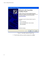
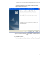
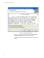
Using the Installer ................................................................................................................................ 89
Using Silent Installation........................................................................................................................ 94
Removing the Device Drivers ..................................................................................................................... 97
Chapter 8: Setting Advanced Properties ......................................................................................................... 99
Accessing the Advanced Tab ...................................................................................................................100
Selecting the Advanced Tab in Windows Server 2003 ......................................................................100
Selecting the Advanced Tab in Windows Server 2008, Windows Server 2008 R2, and Windows 7.103
Selecting the Advanced Tab in Windows Vista..................................................................................104
Modifying Advanced Properties................................................................................................................107
Updating the Ethernet@
WireSpeed Property .................................................................................................................................108
Updating the Flow Control Property ...................................................................................................108
Updating the Interrupt Moderation Property.......................................................................................110
Updating the Checksum Offload Property..........................................................................................111
Updating the Large Send Offload Property ........................................................................................112
Updating the Jumbo MTU Property....................................................................................................113
Updating the Network Address Property............................................................................................114
Updating the RSS Queues Property ..................................................................................................115
Updating the Priority & VLAN Property ..............................................................................................116
Updating the Receive Buffers Property..............................................................................................117
Updating the Receive Side Scaling Property .....................................................................................117
Updating the Speed & Duplex Mode Property ...................................................................................118
Updating the TCP Connection Offload Properties .............................................................................120
Updating the Transmit Buffers Property.............................................................................................121
Updating the VLAN ID Property .........................................................................................................121
Chapter 9: Installing CIM and SNMP for Manageability ................................................................................123
Installing CIM............................................................................................................................................124
Loading the CIM Libraries ..................................................................................................................125
6
AT-2973SX, AT-2973T, and AT-2973T/4 NetExtreme II Family Adapters Installation and User’s Guide
Installing SNMP........................................................................................................................................ 127
BASP Subagent................................................................................................................................. 127
BASP Extensible-Agent ..................................................................................................................... 127
Loading the SNMP Libraries.............................................................................................................. 128
Chapter 10: Installing Management Applications ......................................................................................... 131
Installing Broadcom Advanced Control Suite 3 and Related Management Applications ......................... 132
Checking .NET Framework Requirements ........................................................................................ 133
Using the Installer.............................................................................................................................. 134
Using the Silent Install Option ........................................................................................................... 134
Modifying Management Applications ....................................................................................................... 137
Repairing Management Applications ....................................................................................................... 138
Removing Management Applications....................................................................................................... 139
Chapter 11: Troubleshooting ........................................................................................................................ 141
Checking Hardware Diagnostics .............................................................................................................. 142
Checking Port LEDs................................................................................................................................. 143
Consulting the Troubleshooting Checklist................................................................................................ 144
Checking Current Drivers .................................................................................................................. 144
Running a Cable Length Test............................................................................................................ 145
Testing Network Connectivity ............................................................................................................ 145
Solving Microsoft Windows Server 2008 R2 Hyper-V Issues .................................................................. 147
Single Network Adapter ..................................................................................................................... 147
Teamed Network Adapters................................................................................................................ 147
Removing the Device Drivers ............................................................................................................ 148
Upgrading from Windows Server 2000 to Windows Server 2003 ..................................................... 148
Preparing an Answer File .................................................................................................................. 148
Solving Broadcom Boot Agent and Broadcom Advanced Server Program (BASP) Issues ..................... 150
Solving Miscellaneous Issues .................................................................................................................. 152
Chapter 12: User Diagnostics ....................................................................................................................... 155
Overview .................................................................................................................................................. 156
System Requirements.............................................................................................................................. 157
Performing Diagnostics ............................................................................................................................ 158
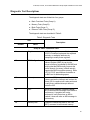
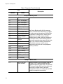
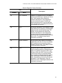
Diagnostic Test Descriptions.................................................................................................................... 161
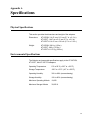
Appendix A: Specifications .......................................................................................................................... 167
Physical Specifications............................................................................................................................. 167
Environmental Specifications ................................................................................................................... 167
Power Specifications................................................................................................................................ 168
Performance Specifications ..................................................................................................................... 168
Operating Specifications .......................................................................................................................... 168
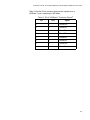
10/100/1000Base-T Twisted-Pair Port Connectors.................................................................................. 168
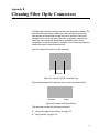
Appendix B: Cleaning Fiber Optic Connectors ............................................................................................ 171
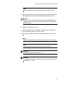
Using a Cartridge-Type Cleaner .............................................................................................................. 172
Using a Swab ........................................................................................................................................... 174
7
Contents
8
Figures
Figure 1. AT-2973SX Adapter .............................................................................................................................................17
Figure 2. AT-2973SX Faceplate ..........................................................................................................................................17
Figure 3. AT-2973T Adapter ................................................................................................................................................18
Figure 4. AT-2973T Faceplate.............................................................................................................................................19
Figure 5. AT-2973T/4 Adapter .............................................................................................................................................20
Figure 6. AT-2973T/4 Faceplate..........................................................................................................................................21
Figure 7. Removing the Low-Profile Bracket .......................................................................................................................32
Figure 8. Fastening Screws onto Standard Bracket ............................................................................................................33
Figure 9. Removing the PC Cover.......................................................................................................................................35
Figure 10. Removing the Faceplate From PCI Slot .............................................................................................................35
Figure 11. Inserting the Adapter with a High-profile Bracket ...............................................................................................36
Figure 12. Securing the Adapter with a High-profile Bracket...............................................................................................37
Figure 13. Found New Hardware Wizard Page ...................................................................................................................90
Figure 14. Broadcom NetXtreme II Driver Installer - InstallShield Wizard Page..................................................................91
Figure 15. License Agreement Page ...................................................................................................................................92
Figure 16. Ready to Install the Program Page.....................................................................................................................93
Figure 17. InstallShield Wizard Completed Page ................................................................................................................94
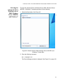
Figure 18. System Properties Dialog Box..........................................................................................................................101
Figure 19. Advanced Tab ..................................................................................................................................................102
Figure 20. Windows Server 2008, Windows Server 2008 R2, and
Windows 7 Search Box ......................................................................................................................................................103
Figure 21. Device Manager Window..................................................................................................................................104
Figure 22. Windows Vista Start Menu ...............................................................................................................................105
Figure 23. Windows Vista Run Window.............................................................................................................................105
Figure 24. BACS CIM Option Window...............................................................................................................................126
Figure 25. BACS SNMP Option Window ...........................................................................................................................129
Figure 26. RJ-45 Connector and Port Pin Layout..............................................................................................................168
Figure 27. Ferrule in an SC Connector Plug......................................................................................................................171
Figure 28. Unclean and Clean Ferrule...............................................................................................................................171
Figure 29. Cartridge Cleaner .............................................................................................................................................172
Figure 30. Rubbing the Ferrule Tip on the Cleaning Surface ............................................................................................172
Figure 31. Lint-Free and Alcohol-Free Swabs ...................................................................................................................174
Figure 32. Cleaning a Recessed Ferrule ...........................................................................................................................174
9
Figures
10
Preface
This guide contains instructions on how to install the AT-2973SX,
AT-2973T, AT-2973T/4 adapters and configure the adapters using the
driver software.
The Preface discusses the following topics:
“Safety Symbols Used in this Document” on page 12
“Where to Find Web-based Guides” on page 13
“Contacting Allied Telesis” on page 14
“Management Software Updates” on page 14
11
Preface
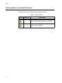
Safety Symbols Used in this Document
This document uses the safety symbols defined in Table 1.
Table 1. Safety Symbols
Symbol
12
Meaning
Description
Caution
Performing or omitting a specific action may
result in equipment damage or loss of data.
Warning
Performing or omitting a specific action may
result in electrical shock.
AT-2973SX,, AT-2973T, and AT-2973T NetExtreme II Family Adapters Installation and User’s Guide
Where to Find Web-based Guides
The installation and user guides for all Allied Telesis products are available
in portable document format (PDF) on our web site at
www.alliedtelesis.com/support/software. After you have accessed this
website, enter the model number in the Search by Product Name box
and then click Find to view the current list of documents.
13
Preface
Contacting Allied Telesis
This section provides Allied Telesis contact information for technical
support as well as sales or corporate information.
Online Support
You can request technical support online by accessing the Allied Telesis
Knowledge Base: www.alliedtelesis.com/support/kb.aspx. You can use
the Knowledge Base to submit questions to our technical support staff and
review answers to previously asked questions.
Email and
Telephone
Support
For Technical Support via email or telephone, refer to the Support section
of the Allied Telesis web site: www.alliedtelesis.com/support.
Returning
Products
Products for return or repair must first be assigned a return materials
authorization (RMA) number. A product sent to Allied Telesis without an
RMA number will be returned to the sender at the sender’s expense. For
instructions on how to obtain an RMA number, go to the Support section
on our web site at www.alliedtelesis.com/support/rma.aspx.
For Sales or
Corporate
Information
You can contact Allied Telesis for sales or corporate information through
our web site at http://www.alliedtelesis.com/purchase.
Warranty
Management
Software Updates
Go to www.alliedtelesis.com/warranty for the specific terms and
conditions of the warranty and for warranty registration for the AT-2973SX,
AT-2973T, and AT-2973T/4 adapters.
New releases of management software for our managed products are
available from both of the following web sites:
Allied Telesis web site: www.alliedtelesis.com/support/software/
Allied Telesis FTP server:ftp://ftp.alliedtelesis.com
If you prefer to download new software from the Allied Telesis FTP server
from your workstation’s command prompt, you will need FTP client
software and you must log in to the server. Enter “anonymous” for the user
name and your email address for the password.
14
Chapter 1
Introducing the AT-2973SX, AT-2973T,
and AT-2973T/4 Adapters
This chapter provides an introduction to the Allied Telesis AT-2973SX,
AT-2973T, and AT-2973T/4 NetExtreme II Family Adapters and discusses
the following topics:
“Functional Descriptions” on page 16
“Features” on page 22
15
Chapter 1: Introducing the AT-2973SX, AT-2973T, and AT-2973T/4 Adapters
Functional Descriptions
The AT-2973SX, AT-2973T, and AT-2973T/4 Broadcom NetXtreme II
adapters are a new class of Gigabit Ethernet (GbE) converged network
interface controller (C-NIC) that can simultaneously perform accelerated
data networking and storage networking on a standard Ethernet network.
The C-NIC offers acceleration for all popular protocols used in the data
center, such as:
TCP Offload Engine (TOE) for accelerating TCP
Internet Small Computer Systems Interface (iSCSI) offload for
accelerating network storage access featuring centralized boot
functionality (iSCSI boot)
Enterprise networks that use multiple protocols and multiple network
fabrics benefit from the C-NICs ability to combine data communications,
storage, and clustering over a single Ethernet fabric by boosting server
CPU processing performance and memory utilization while alleviating I/O
bottlenecks.
The AT-2973SX adapter is set to a speed of 1000 Mbps in full duplex
mode automatically. You cannot change the speed or duplex mode of this
adapter.
The AT-2973T and AT-2973T/4 adapters include a 10/100/1000-Mbps
Ethernet MAC with both half-duplex and full-duplex capability and a 10/
100/1000-Mbps PHY. The transceiver is fully compatible with the IEEE
802.3 standard for auto-negotiation of speed.
As part of the company’s green range, all of three adapters are
engineered to reduce power consumption. They incorporate centralized
power management features that automatically place idle circuitry into a
lower power mode to save energy.
The following sections provide functional descriptions of the AT-2973SX,
AT-2973T, and AT-2973T/4 adapters:
16
“AT-2973SX Adapter” on page 17
“AT-2973T Adapter” on page 18
“AT-2973T/4 Adapter” on page 20
AT-2973SX, AT-2973T, and AT-2973T/4 NetExtreme II Family Adapters Installation and User’s Guide
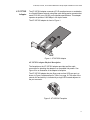
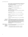
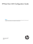
The AT-2973SX adapter connects a PCI-E compliant server or workstation
to a Gigabit Ethernet network using fiber optic cabling and a connector that
meets 62.5/125 µm or 50/125 µm multimode specifications. This adapter
operates at speeds of 1000 Mbps in full-duplex mode.
The AT-2973SX adapter is show in Figure 1.
10
0
ATI
ACT LNK
1696
Figure 1. AT-2973SX Adapter
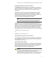
AT-2973SX Adapter Physical Description
The faceplate on the AT-2973SX adapter provides two fiber optic
connectors for attaching the adapter to a compatible link partner. See
Figure 2 for an illustration of the adapter’s faceplate.
The AT-2973SX adapter has two fiber ports and two LEDs per port, as
shown in Figure 2 and described in Table 1 on page 18. The state of the
network link and activity is indicated by a single LED located adjacent to
the port connector.
LNK
10
0
ACT
AT-2973SX
Adapter
1699
Figure 2. AT-2973SX Faceplate
17
Chapter 1: Introducing the AT-2973SX, AT-2973T, and AT-2973T/4 Adapters
For AT-2973SX LED information, see Table 1.
Table 1. Network Link and Activity Indicated by the RJ-45 Port LEDs
Port LED
Link LED
Activity LED
AT-2973T
Adapter
LED Appearance
Network State
Off
No link (cable disconnected)
Continuously
illuminated
Link
Off
No network activity
Blinking
No network activity
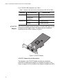
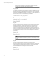
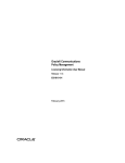
The AT-2973T adapter operates at speeds of 10/100/1000T Mbps in both
full-duplex and half-duplex modes. This adapter has two twisted-pair
connectors and two LEDs, as shown in Figure 3.
L/A
101
0
2
ATI
L/A
1700
Figure 3. AT-2973T Adapter
AT-2973T Adapter Physical Description
The faceplate on the AT-2973T adapter provides two twisted-pair
connectors for attaching the adapter to a compatible link partner. See
Figure 4 on page 19 for an illustration of the adapter’s faceplate and LEDs.
18
AT-2973SX, AT-2973T, and AT-2973T/4 NetExtreme II Family Adapters Installation and User’s Guide
L/A
101
L/A
0
2
1701
Figure 4. AT-2973T Faceplate
For copper-wire Ethernet connections, the state of the network link and
activity is indicated by the LEDs on the RJ-45 connector. The LED labeled
L/A1 indicates port 1 and the LED labeled L/A2 indicates port 2. See
Table 2.
Table 2. Network Link and Activity Indicated by the RJ-45 Port LEDs
Port LED
Link LED
Activity LED
LED Appearance
Network State
Off
No link (cable disconnected)
Continuously
illuminated
Link
Off
No network activity
Blinking
No network activity
19
Chapter 1: Introducing the AT-2973SX, AT-2973T, and AT-2973T/4 Adapters
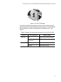
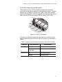
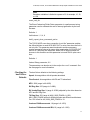
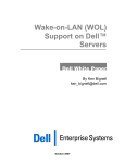
AT-2973T/4
Adapter
The AT-2973T/4 adapter is a PCI-Express adapter that operates at
speeds of 10/100/1000T Mbps in both full-duplex and half-duplex modes.
This adapter has four twisted-pair connectors and eight LEDs, as shown in
Figure 5.
LN
K
T
ATI
AC
T
1861
Figure 5. AT-2973T/4 Adapter
20
AT-2973SX, AT-2973T, and AT-2973T/4 NetExtreme II Family Adapters Installation and User’s Guide
AT-2973T/4 Adapter Physical Description
The faceplate on the AT-2973T/4 adapter provides four twisted-pair
connectors for attaching the adapter to a compatible link partner. The ports
numbers are not shown on the card. See Figure 6 for the port numbers
and the LED assignments. When the adapter is mounted vertically, the top
LED is the Link LED and the bottom LED is the activity (ACT) LED.
LINK ACT
LN
K
T
PORT 1
PORT 2
AC
T
1862
PORT 4
ATI
PORT 3
Figure 6. AT-2973T/4 Faceplate
For copper-wire Ethernet connections, the state of the network link and
activity is indicated by the LEDs on the RJ-45 connector, as described in
Table 3.
Table 3. Network Link and Activity Indicated by the RJ-45 Port LEDs
Port LED
Link LED
Activity LED
LED Appearance
Network State
Off
No link (cable disconnected)
Continuously
illuminated
Link
Off
No network activity
Blinking
Network activity
21
Chapter 1: Introducing the AT-2973SX, AT-2973T, and AT-2973T/4 Adapters
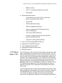
Features
The following list of features for the AT-2973SX, AT-2973T, AT-2973T/4
adapters applies to all of the supported operating systems:
TCP Offload Engine (TOE)
Internet Small Computer Systems Interface (iSCSI) offload
Single-chip solution
22
–
Integrated 10/100/1000BASE-T transceivers
–
10/100/1000 triple-speed MAC
–
Host interfaces
–
SerDes interface for optical transceiver
connection
–
PCI Express v1.1 x4 and v2.0 compliant (Gigabit
Ethernet)
–
Full fast-path TCP offload
Other performance features
–
TCP, IP, UDP checksum
–
TCP segmentation
–
Adaptive interrupts
–
Receive Side Scaling (RSS)
Manageability
–
Broadcom Advanced Control Suite (BACS) 3
diagnostic and configuration software suite
–
Supports PXE 2.0 specification (Linux Red
Hat PXE Server, SUSE Linux Enterprise
Server, Windows Server 2000, Windows Server
2003, Windows Server 2008, Windows Server
2008 R2, Intel APITEST, DOS UNDI)
–
Wake on LAN support
–
Statistics for Simple Network Management
Protocol (SNMP) MIB II, Ethernet-like MIB, and
Ethernet MIB (IEEE Std 802.3z, Clause 30)
AT-2973SX, AT-2973T, and AT-2973T/4 NetExtreme II Family Adapters Installation and User’s Guide
TCP Offload
Engine (TOE)
–
SMBus controller
–
ACPI 1.1a compliant (multiple power modes)
–
IPMI support
Advanced network features
–
Jumbo frames (up to 9 KB). The OS and the link
partner must support jumbo frames.
–
Virtual LANs
–
IEEE Std 802.3ad Teaming
–
Smart Load Balancing Teaming
–
Smart Load Balancing TOE Teaming (with the
correct configuration)
–
Flow Control (IEEE Std 802.3x)
–
LiveLink™ (supported in both the 32-bit and 64-bit
Windows operating systems)
–
Logical Link Control (IEEE Std 802.2)
Layer-2 Priority Encoding (IEEE Std 802.1p)
High-speed on-chip RISC processor
Up to 4 classes of service (CoS)
Integrated 96 KB frame buffer memory
iSCSI Boot support
The TCP/IP protocol suite is used to provide transport services for a wide
range of applications for the Internet, LAN, and for file transfer. The TCP
protocol is specifically designed to insure that data packets are delivered
error free and in the correct sequence from an application running a one
computer to the receiving application. The TCP protocol suite historically
has run on the host CPU, but with higher data rates, this consumes a very
high percentage of its resources while leaving little resources for the
applications. With the use of the Broadcom NetXtreme II adapter and the
TCP Offload Engine feature, the TCP/IP processing can be moved to
hardware, freeing the CPU for application processing and other higher
priority tasks.
The TCP/IP protocol suite is used to provide transport services for a wide
range of applications for the Internet, LAN, and for file transfer. Without the
TCP Offload Engine, the TCP/IP protocol suite runs on the host CPU,
consuming a very high percentage of its resources and leaving little
resources for the applications. With the use of the Broadcom NetXtreme II
23
Chapter 1: Introducing the AT-2973SX, AT-2973T, and AT-2973T/4 Adapters
adapter, the TCP/IP processing can be moved to hardware, freeing the
CPU for more important tasks such as application processing.
The Broadcom NetXtreme II adapter's TOE functionality allows
simultaneous operation of up to 1024 fully offloaded TCP connections for
1-Gbps network adapters. The TOE support on the adapter significantly
reduces the host CPU utilization while preserving the implementation of
the operating system stack.
Internet Small
Computer
Systems Interface
(iSCSI)
The IETF has standardized the Internet Small Computer Systems
Interface (iSCSI). SCSI is a popular protocol that enables systems to
communicate with storage devices, using block-level transfer (that is,
address data stored on a storage device that is not a whole file). In
addition, iSCSI maps the SCSI request and response application
protocols and its standardized command set over TCP/IP networks.
As iSCSI utilizes TCP as its sole transport protocol, it greatly benefits from
hardware acceleration of the TCP processing (that is, use of a TOE).
However, iSCSI as a Layer 5 protocol has additional mechanisms beyond
the TCP layer. iSCSI processing can also be offloaded, thereby reducing
CPU utilization even further.
The Broadcom NetXtreme II adapter targets best-system performance,
maintains system flexibility to changes, and supports current and future
OS convergence and integration. Therefore, the adapter's iSCSI offload
architecture is unique as evident by the split between hardware and host
processing.
Power
Management
When the system is down and waiting for a wake-up signal, the adapter
speed connection may be at 10 Mbps or 100 Mbps. However, it can return
to 1000 Mbps when the system is up and running if it is connected to a
1000 Mbps capable switch. For this reason, connect systems that use the
Wake on LAN (WOL) feature to a switch capable of both 1000 and 10/100
Mbps speeds.
Wake on LAN
(WOL) Feature
The WOL feature sets the speed at which the network adapter connects to
the network while the adapter is in Wake on LAN (WOL) mode which is
enabled automatically. The default speed for WOL mode is 100 Mb. An
adapter can negotiate speeds between 10 Mb and 100 Mb. You cannot
configure this feature because it is enabled automatically.
Note
The WOL feature is supported on the AT-2973T and AT-2973T/4
adapters. It is not supported on the AT-2973SX adapter. For more
information, see “Limitations” on page 66.
24
AT-2973SX, AT-2973T, and AT-2973T/4 NetExtreme II Family Adapters Installation and User’s Guide
Note
For specific systems, see your system documentation for
information about support of the WOL feature.
Adaptive
Interrupt
Frequency
The adapter driver intelligently adjusts host interrupt frequency based on
traffic conditions to increase overall application throughput. When traffic is
light, the adapter driver interrupts the host for each received packet,
minimizing latency. When traffic is heavy, the adapter issues one host
interrupt for multiple, back-to-back incoming packets, preserving host CPU
cycles.
ASIC with
Embedded RISC
Processor
The core control for Broadcom NetXtreme II adapters resides in a tightly
integrated, high-performance ASIC. The ASIC includes a RISC processor.
This functionality provides the flexibility to add new features to the card
and adapts it to future network requirements through software downloads.
This functionality also enables the adapter drivers to exploit the built-in
host offload functions on the adapter as host operating systems are
enhanced to take advantage of these functions.
Supported
Operating
Environments
The Broadcom NetXtreme II adapter has software support for the following
operating systems:
Microsoft Windows Server 2003 (32-bit and 64-bit extended)
Microsoft Windows Server 2008 (32-bit and 64-bit extended)
Microsoft Windows Server 2008 R2 (32-bit and 64-bit extended)
Microsoft Windows Vista (32-bit and 64-bit extended)
Microsoft Windows 7 (32-bit and 64-bit extended)
Microsoft Windows Server 2008 R2 Hyper-V
Linux (32-bit and 64-bit extended)
MS-DOS
ESX Server (VMware)
Citrix XenServer
25
Chapter 1: Introducing the AT-2973SX, AT-2973T, and AT-2973T/4 Adapters
26
Chapter 2
Installing the Hardware
This chapter describes how to install the AT-2973SX, AT-2973T, and
AT-2973T/4 adapters in a PC and discusses the following topics:
“Reviewing the Contents of Your Shipment” on page 28
“Reviewing Safety Precautions” on page 29
“Pre-Installation Checklist” on page 31
“Replacing the Bracket” on page 32
“Installing a Network Adapter Card” on page 34
“Connecting the Network Cables” on page 38
27
Chapter 2: Installing the Hardware
Reviewing the Contents of Your Shipment
The following items are included with your adapter:
Antistatic bag (used for protecting the adapter when stored or
shipped). Keep the adapter in its packaging until ready for installation.
Low-profile bracket (The low-profile bracket is not included with the
AT-2973T/4 adapter.)
Standard bracket
Inform your network supplier of any missing or damaged items. If you
need to return the adapter, you must pack it in the original (or equivalent)
packing material or the warranty will be voided. See “Returning Products”
on page 14.
The documentation for these adapters is available in portable document
format (PDF) on our web site at www.alliedtelesis.com/support/
software. After you have accessed this website, enter the model number
in the Search by Product Name box and then click Find to view the
current list of documents.
28
AT-2973SX, AT-2973T, and AT-2973T/4 NetExtreme II Family Adapters Installation and User’s Guide
Reviewing Safety Precautions
Please review the following safety precautions before you begin to install a
network adapter card.
Note
The indicates that a translation of the safety statement is
available in a PDF document titled “Translated Safety Statements”
on the Allied Telesis website at www.alliedtelesis.com/support/
software. After you have accessed this website, enter the model
number in the Search by Product Name box and then click Find to
view the current list of documents.
Warning
This is a “Class 1 Laser product”. L1
Warning
Do not stare into the laser beam. L2
Warning
Do not look directly at the fiber optic cable ends or inspect the cable
ends with an optical lens. E29
Warning
Do not work on this equipment or cables during periods of lightning
activity. E2
Note
All Countries: Install this product in accordance with local and
National Electric Codes. E8
Warning
The adapter is being installed in a system that operates with
voltages that can be lethal. Before you remove the cover of your
system, you must observe the following precautions to protect
yourself and to prevent damage to the system components.
- Remove any metallic objects or jewelry from your hands and
wrists.
- Make sure to use only insulated or nonconducting tools.
- Verify that the system is powered OFF and unplugged before
29
Chapter 2: Installing the Hardware
accessing internal components.
- Installation or removal of adapters must be performed in a staticfree environment. The use of a properly grounded wrist strap or
other personal antistatic devices and an antistatic mat is strongly
recommended. E39
30
AT-2973SX, AT-2973T, and AT-2973T/4 NetExtreme II Family Adapters Installation and User’s Guide
Pre-Installation Checklist
Before you install an adapter card, do the following:
1. Verify that your system is using the latest BIOS.
Note
If you acquired the adapter software from the Allied Telesis support
website, enter the path to where the adapter driver files reside on
your system.
2. If your system is active, shut it down.
3. When the system shut down is complete, power OFF and unplug your
system.
4. Holding the adapter card by the edges, remove it from its shipping
package and place it on an antistatic surface.
5. Check the adapter for visible signs of damage, particularly on the
card’s edge connector.
Caution
Do not attempt to install a damaged adapter. If the adapter is
damaged, report it to Allied Telesis. See “Contacting Allied Telesis”
on page 14.
31
Chapter 2: Installing the Hardware
Replacing the Bracket
Both the AT-2973SX and AT-2973T adapters are shipped with the lowprofile bracket attached to the adapter. In addition, the standard bracket is
included in the shipment. Depending on your PC, you may need to replace
the bracket attached to your adapter.
Note
The AT-2973T/4 adapter is shipped with a standard bracket
attached to the card. A low-profile bracket is not included with this
adapter.
The following procedure describes how to remove the low-profile bracket
from the adapter and replace it with the standard bracket. You can also
use this procedure to remove the standard bracket and replace it with the
low-profile bracket.
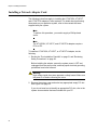
To replace the low-profile bracket with the standard bracket, do the
following:
ATI
ACT LNK
1. Remove the screws that attach the bracket to the adapter. See
Figure 7.
1697
Figure 7. Removing the Low-Profile Bracket
32
AT-2973SX, AT-2973T, and AT-2973T/4 NetExtreme II Family Adapters Installation and User’s Guide
ATI
ACT LNK
2. Align the tabs of the standard bracket with the holes on the adapter
and fasten the screws onto the adapter. See Figure 8.
1698
Figure 8. Fastening Screws onto Standard Bracket
33
Chapter 2: Installing the Hardware
Installing a Network Adapter Card
The following instructions apply to installing the AT-2973SX, AT-2973T,
and AT-2973T/4 adapters in most systems. For details about performing
these tasks on your particular system, refer to the manuals that were
supplied with your system.
Note
To perform this procedure, you need to supply a Phillips-head
screw.
Note
The AT-2973SX, AT-2973T, and AT-2973T/4 adapters require a
PCIe x4 PC.
To install an AT-2973SX, AT-2973T, or AT-2973T/4 adapter, do the
following:
1. Review the “Pre-Installation Checklist” on page 31 and “Reviewing
Safety Precautions” on page 29.
Before installing the adapter, ensure the system power is OFF and
unplugged from the power outlet, and that proper electrical grounding
procedures have been followed.
Warning
High voltage inside the system presents a safety hazard. Make sure
the power is off before removing the cover.
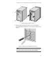
2. Remove the system cover and select any appropriate empty PCI slot.
See Figure 9 on page 35.
If you do not know how to identify an appropriate PCI slot, refer to the
system documentation that was included with your PC.
34
AT-2973SX, AT-2973T, and AT-2973T/4 NetExtreme II Family Adapters Installation and User’s Guide
Figure 9. Removing the PC Cover
3. Select an empty, non-shared PCI slot and remove the faceplate.
Keep the faceplate in a safe place. You may need it for future use. See
Figure 10.
Figure 10. Removing the Faceplate From PCI Slot
Note
If you cannot locate or do not know how to find an appropriate PCI
slot, refer to the documentation that came with your system.
35
Chapter 2: Installing the Hardware
4. Remove the network adapter card from the shipping package and
store the packaging material in a safe location.
Caution
Wear a grounding device and observe electrostatic discharge
precautions when installing the network adapter card in a system.
Failure to observe this caution could result in damage to the card.
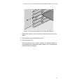
5. Applying even pressure at both corners of the card, push the adapter
card until it is firmly seated in the appropriate PCI slot.
Make sure the card is securely seated. To insert the network adapter
card, see Figure 11.
Figure 11. Inserting the Adapter with a High-profile Bracket
Caution
Do not use excessive force when seating the card, because this
may damage the system or the adapter. If the card resists seating,
remove it from the system, realign it, and try again.
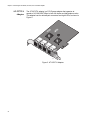
6. Secure the network adapter card to the chassis with a Phillips-head
screw (not provided). See Figure 12 on page 37.
36
AT-2973SX, AT-2973T, and AT-2973T/4 NetExtreme II Family Adapters Installation and User’s Guide
Figure 12. Securing the Adapter with a High-profile Bracket
7. Replace the system’s cover and secure it with the screws removed in
Step 2.
8. Disconnect any personal antistatic devices.
9. Power the system on.
Once the system returns to proper operation, the adapter hardware is
fully installed. Next, connect the network cables. See “Connecting the
Network Cables” on page 38.
37
Chapter 2: Installing the Hardware
Connecting the Network Cables
After you install the adapter in your PC, attach the system to a compatible
link partner or an IEEE 802.3z compliant Gigabit Ethernet switch.
The AT-2973SX adapter has two fiber optic connectors, each with a
transmit and receive connector. This adapter requires a fiber optic cable.
For cable specifications, see the AT-2973SX adapter data sheet.
Note
For information about cleaning a fiber optic connector, see Appendix
B “Cleaning Fiber Optic Connectors” on page 171.
The AT-2973T adapter has two twisted-pair connectors and the
AT-2973T/4 adapter has four twisted-pair connectors. Both adapters
require twisted-pair cables. For pin signals and pinout information, see
“10/100/1000Base-T Twisted-Pair Port Connectors” on page 168.
To connect the network cables to an AT-2973SX, AT-2973T, or
AT-2973T/4 adapter, do the following:
Warning
The fiber optic ports contain a Class 1 laser device. When the ports
are disconnected, always cover them with the provided plug.
Exposed ports may cause skin or eye damage. L4
1. Connect one end of the cable to the adapter.
–
For the AT-2973SX adapter, use a fiber optic
cable.
–
For the AT-2973T and AT-2973T/4 adapters, use
a twisted-pair cable.
2. For the AT-2973SX adapter, connect the other end of the cable to the
appropriate Ethernet fiber optic port. For the AT-2973T and
AT-2973T/4 adapters, connect the other end of the cable to another
twisted pair port.
Note
After the cable is properly connected at both ends, the adapter port
LEDs should be functional. See “AT-2973SX Adapter Physical
Description” on page 17, “AT-2973T Adapter Physical Description”
on page 18, or “AT-2973T/4 Adapter Physical Description” on
page 21 for a description of LED operation for each adapter model.
38
AT-2973SX, AT-2973T, and AT-2973T/4 NetExtreme II Family Adapters Installation and User’s Guide
After you connect the system to the network and power is supplied, the
AT-2973SX, AT-2973T, and AT-2973T/4 adapters attempt to establish
the connection at 1000 Mbps in full-duplex mode.
39
Chapter 2: Installing the Hardware
40
Chapter 3
Installing Broadcom Boot Agent Driver
Software
This chapter provides information about how to install the Broadcom Boot
Agent Driver Software and discusses the following topics:
“Overview” on page 42
“Setting Up MBA in a Client Environment” on page 43
“Setting Up MBA in a Server Environment: Red Hat Linux PXE Server”
on page 45
41
Chapter 3: Installing Broadcom Boot Agent Driver Software
Overview
The AT-2973SX, AT-2973T, and AT-2973T/4 NetXtreme II Family
adapters support Preboot Execution Environment (PXE). Multi-Boot Agent
(MBA) is a software module that allows your network computer to boot
with the images provided by remote servers across the network. The
Broadcom MBA driver complies with PXE 2.1 code.
The MBA module operates in a client/server environment. A network
consists of one or more boot servers that provide boot images to multiple
computers through the network. The Broadcom implementation of the
MBA module has been tested successfully in the following environments:
42
Linux Red Hat PXE Server. Broadcom PXE clients are able to
remotely boot and use network resources (NFS mount, and so forth)
as well as perform Linux installations. In the case of a remote boot, the
Linux universal driver binds seamlessly with the Broadcom Universal
Network Driver Interface (UNDI) and provides a network interface in
the Linux remotely-booted client environment.
Intel APITEST. The Broadcom PXE driver passes all API compliance
test suites.
MS-DOS UNDI. The MS-DOS Universal Network Driver Interface
(UNDI) seamlessly binds with the Broadcom UNDI to provide a
network adapter driver interface specification (NDIS2) interface to the
upper layer protocol stack. This allows computers to connect to
network resources in an MS-DOS environment.
Remote Installation Service (RIS). The Broadcom PXE clients are
able to remotely boot to a Windows Server 2003 (SP1 and older)
system running RIS to initialize and install Windows Server 2003 and
prior operating systems. To extend functionalities beyond basic
network connectivity when loading an operating system through RIS,
see “Using the NetXtreme II Monolithic Driver” on page 48.
Windows Deployment Service (WDS). For Windows Server 2003
SP2, RIS was replaced by WDS, which offers a Broadcom PXE client
to install Windows operating systems, including Windows Vista,
Windows Server 2008 and Windows Server 2008 R2. To extend
functionalities beyond basic network connectivity when loading an
operating system through WDS, see “Using the NetXtreme II
Monolithic Driver” on page 48.
Automated Deployment Service (ADS). The Broadcom PXE client
can connect to a Windows Server 2003 system and run a deployment
agent that allows one to perform some administrative functions,
including, but not limited to, deploying a Windows Server 2003 image.
To extend functionalities beyond basic network connectivity when
loading an operating system through ADS, see “Using the NetXtreme
II Monolithic Driver” on page 48.
AT-2973SX, AT-2973T, and AT-2973T/4 NetExtreme II Family Adapters Installation and User’s Guide
Setting Up MBA in a Client Environment
Setting up a Multiple Book Agent (MBA) in a client environment involves
the following:
Enabling the
MBA Driver
“Enabling the MBA Driver” on page 43
“Configuring the MBA Driver” on page 43
“Setting Up the BIOS” on page 44
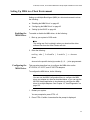
To enable or disable the MBA driver, do the following:
1. Boot up your system in DOS mode.
Note
The uxdiag.exe file is included in when you download the driver
software files from the Allied Telesis web site.
2. Enter the following:
uxdiag -mba [ 0-disable | 1-enable ] -c devnum
where
devnum is the specific device(s) number (0,1,2, ...) to be programmed.
Configuring the
MBA Driver
This procedure describes how to configure the MBA driver on the
AT-2973SX, AT-2973T, and AT-2973T/4 adapters.
To configure the MBA driver, do the following:
Note
You can use the MBA Configuration Menu to configure the MBA
driver one adapter at a time as described below, or you can use the
MS-DOS based application to simultaneously configure the MBA
driver for multiple adapters. See Chapter 12, “User Diagnostics” on
page 155.
1. Restart your system.
You are prompted to press CTRL +S.
2. Press CTRL+S within 4 seconds after the prompt is displayed.
43
Chapter 3: Installing Broadcom Boot Agent Driver Software
Note
The message prompting you to press CTRL+S is displayed once for
each Broadcom NetXtreme II adapter you have in your system that
has MBA enabled. The messages are displayed in the same order
as the assigned adapter device number.
3. Use the UP ARROW and DOWN ARROW keys to move to the Boot
Protocol menu item.
Note
If you have multiple adapters in your system and you are unsure
which adapter you are configuring, press CTRL+F6, which causes
the port LEDs on the adapter to start blinking.
4. Use the UP ARROW, DOWN ARROW, LEFT ARROW, and RIGHT
ARROW keys to move to and change the values for other menu items,
as desired.
5. Press F4 to save your settings.
6. Press ESC when you are finished.
Setting Up the
BIOS
44
To boot from the network with the MBA, make the MBA enabled adapter
the first bootable device under the BIOS. This procedure depends on the
system BIOS implementation. Refer to the user manual for the system
BIOS implementation for instructions.
AT-2973SX, AT-2973T, and AT-2973T/4 NetExtreme II Family Adapters Installation and User’s Guide
Setting Up MBA in a Server Environment: Red Hat Linux PXE Server
The Red Hat Enterprise Linux distribution has PXE Server support. It
allows users to remotely perform a complete Linux installation over the
network. The distribution comes with the boot images boot kernel
(vmlinuz) and initial ram disk (initrd), which are located on the Red Hat
disk#1:
/images/pxeboot/vmlinuz
/images/pxeboot/initrd.img
Refer to the Red Hat documentation for instructions on how to install PXE
Server on Linux.
However, the Initrd.img file distributed with Red Hat Enterprise Linux, does
not have a Linux network driver for the Broadcom NetXtreme II adapters.
This version requires a driver disk for drivers that are not part of the
standard distribution. You download the driver software files from the
Allied Telesis web site.
45
Chapter 3: Installing Broadcom Boot Agent Driver Software
46
Chapter 4
Installing the Monolithic Software
Driver
A monolithic driver allows you to download an image of a PC onto an
image server and then to another PC with an adapter installed. Often,
multiple images are downloaded. The NetXtreme II Monolithic software
driver allows remote installation of an image of a PC with an AT-2973SX,
AT-2973T, or AT-2973T/4 adapter installed. This chapter describes how to
install the monolithic driver software for remote installation and discusses
the following topics:
“Using the NetXtreme II Monolithic Driver” on page 48
“Inserting the NetXtreme II Monolithic Driver in a WinPE 2.0 Image” on
page 50
“Configuring the Speed and Duplex Settings” on page 52
47
Chapter 4: Installing the Monolithic Software Driver
Using the NetXtreme II Monolithic Driver
The NetXtreme II Monolithic driver is used with a remote imaging software
such as WinPE, although it is not associated with any operating system.
Before you install a monolithic driver, you must install an AT-2973SX, AT2973T, or AT-2973T/4 adapter in a PC (or multiple PCs) that you want to
act as a remote node. Once you install the adapter and the monolithic
driver software, your can download the image from an image server to the
PCs with an installed adapter.
The NetXtreme II Family Adapters, based on its advanced functionalities,
uses a software architecture that includes a Virtual Bus Device (VBD) to
extend functionalities beyond basic network connectivity. However,
Microsoft, does not currently support this architecture when loading an
operating system through its Windows Deployment Services (WDS),
which was previously known as Remote Installation Services (RIS), or for
the deployment agent used in the Automated Deployment Services (ADS).
Therefore, a separate driver was created to accommodate these Microsoft
deficiencies. This driver is known as the NetXtreme II monolithic driver,
but it is sometimes referred to as the RIS driver.
The NetXtreme II monolithic driver was developed to work only for the text
mode portion of a WDS legacy installation and to establish connectivity
with a deployment agent for ADS. It is not intended to be used as a driver
loaded in the running state of an operating system. The exception to this is
the Windows Preinstallation Environment (WinPE).
For WDS, this driver is used similarly to any other network adapter driver
for supporting network connectivity after the PXE boot to the WDS server.
When placed in the I386 or AMD64 directory (depending on the version of
the operating system being deployed), the monolithic driver is called to
establish that there is driver support for the NetXtreme II Family Adapter
included in the WDS legacy image.
For ADS, the driver is placed in the PreSystem directory on the server
running ADS to establish connectivity with the deployment agent on
remote systems with NetXtreme II adapters when booting from PXE.
While Windows PE 2005 natively supports the VBD architecture, it was
found that using the minint switch in the startnet.cmd file does not. The
minint switch performs a limited scan of the system bus to identify network
devices only and, therefore, does not support the VBD architecture. Since
only network connectivity is required in Windows PE, the only supported
driver is the monolithic driver for the NetXtreme II Family adapter in this
environment as well. Place the b06nd.inf file in the INF directory within the
Windows PE image, and place the appropriate driver file (b06nd51a.sys
for x64-based builds or b06nd51.sys for x86-based builds) in the driver's
48
AT-2973SX, AT-2973T, and AT-2973T/4 NetExtreme II Family Adapters Installation and User’s Guide
directory. If Windows PE is deployed as a flat image from a RIS or WDS
server, you must also place both the b06nd.inf and the appropriate driver
file in the I386 or AMD64 directory containing the image.
49
Chapter 4: Installing the Monolithic Software Driver
Inserting the NetXtreme II Monolithic Driver in a WinPE 2.0 Image
By default, the monolithic driver is not included in the boot.wim and
install.wim files that come with the Windows Vista, Windows Server 2008,
and Windows Server 2008 R2 Operating Systems. Microsoft's Windows
Automated Installation Kit (AIK) allows you to modify the default boot.wim
and install.wim files and create WinPE 2.0 images to include the
NetXtreme II monolithic driver in the Windows Vista, Windows Server
2008, and Windows Server 2008 R2 installation.
To insert Broadcom's NetXtreme II monolithic driver in a WinPE 2.0 image
(for Windows Vista, Windows Server 2008, and Windows Server 2008
R2), download AIK from www.microsoft.com/downloads/
Search.aspx?displaylang=en, type in “automated install kit” in the Search
field. Then install AIK.
After installing AIK, copy the latest monolithic driver to a directory on the
local hard drive of the system you installed the AIK. Follow the procedure
below to insert the monolithic driver into a WinPE 2.0 boot image.
Note
The directory structure c:\VistaPEx86 is used throughout this
procedure.
To insert the monolithic driver into a WinPE 2.0 boot image, do the
following:
1. Download the monolithic driver files, b06nd.inf and b06nd.sys.
Go to the Allied Telesis website at www.alliedtelesis.com/support/
software. After you have accessed this website, enter the model
number in the Search by Product Name box and then click Find to
view the current list of files.
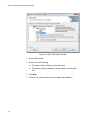
2. From All Programs, open Windows AIK and select Windows PE
Tools Command prompt.
3. At the command prompt, run the copype.cmd script. The script
requires two arguments: hardware architecture and destination
location. The command syntax is:
copype.cmd <arch> <destination>
For example: copype x86 c:\VistaPEx86
50
AT-2973SX, AT-2973T, and AT-2973T/4 NetExtreme II Family Adapters Installation and User’s Guide
4. Mount the base image to a local directory so that you can add or
remove packages by entering:
imagex /mountrw c:\VistaPEx86\winpe.wim 1
c:\VistaPEx86\mount
5. Place the monolithic driver and inf file in c:\drivers\x32\ by entering:
peimg /inf=c:\Drivers\x32\b06nd.inf
c:\VistaPEx86\mount\windows
AIK inserts the driver into the WinPE 2.0 image.
6. To complete the customization of the image, prepare the image for
deployment, enter:
peimg /prep c:\VistaPEx86\mount\windows
7. When asked to continue and have the program prepare the image for
deployment, enter:
yes
8. To commit the changes to the original image file (Winpe.wim), enter:
imagex /unmount c:\VistaPEx86\mount /commit
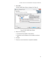
9. To replace the default Boot.wim file in the \ISO directory with your new
custom image, enter:
copy c:\VistaPex86\winpe.wim
c:\VistaPEx86\ISO\sources\boot.wim
51
Chapter 4: Installing the Monolithic Software Driver
Configuring the Speed and Duplex Settings
Since the typical environment where the NetXtreme II monolithic driver is
used does not provide the means to configure advanced network adapter
properties, the driver file (b06nd.inf) was modified to include a section that
allows it to be configured for a specific speed and duplex mode. This
provides a more robust connection to the network as it allows the adapter
to match the settings of its link partner (for example, a switch or a router).
To manually configure the speed and duplex, do the following:
1. Open the b06nd.inf file with a text editor like Microsoft Notepad or
WordPad.
2. Search the file for Registry parameters to locate the section that allows
you to configure the adapter speed and duplex mode.
Once located, notice the following information:
[params_utp]
hkr, , req_medium,
2, "0"
[params_fiber]
hkr, , req_medium,
2, "65283"
These are two separate sections that can be configured: one for
standard RJ-45 copper interfaces (params_utp) and one for fiber
devices (params_fiber).
3. As described in the file, replace the value above in quotation marks
under the correct section, depending upon the network adapter in your
system. The available values are shown below.
Options for copper interfaces:
52
–
Auto (1 Gbps is enabled when that speed is
supported) = "0"
–
10 Mbps Half Duplex = "65794"
–
10 Mbps Full Duplex = "258"
–
100 Mbps Half Duplex = "66050"
–
100 Mbps Full Duplex = "514"
AT-2973SX, AT-2973T, and AT-2973T/4 NetExtreme II Family Adapters Installation and User’s Guide
Options for fiber interfaces:
–
Auto (1 Gbps is enabled when that speed is
supported) = "0"
–
1 Gbps Full Duplex = "771"
–
Auto with 1 Gbps Fallback = "33539"
–
Hardware default = "65283"
The following example shows how to configure a copper interface for a
10 Mbps Full Duplex connection:
hkr, , req_medium,
2, "258"
53
Chapter 4: Installing the Monolithic Software Driver
54
Chapter 5
Installing the NDIS2 Driver Software
This chapter provides procedures to install the NDIS2 driver on the
Microsoft Network Client and DOS NDIS platforms.
This chapter discusses the following topics:
“Overview” on page 56
“Checking Pre-installation Requirements” on page 57
“Installing the NDIS2 Driver Software on MS-DOS Platforms” on
page 58
“Using Keywords for the Drivers” on page 63
55
Chapter 5: Installing the NDIS2 Driver Software
Overview
The BXND20X Broadcom NetXtreme II Gigabit Ethernet driver is
described in this chapter. This driver can be installed on AT-2973SX,
AT-2973T, and AT-2973T/4 adapters that are installed in systems running
an MS-DOS platform. See the following sections:
56
“Checking Pre-installation Requirements” on page 57
“Installing the NDIS2 Driver Software on MS-DOS Platforms” on
page 58
“Using Keywords for the Drivers” on page 63
AT-2973SX, AT-2973T, and AT-2973T/4 NetExtreme II Family Adapters Installation and User’s Guide
Checking Pre-installation Requirements
Before you can successfully install the NDIS2 driver software, you must do
the following:
Physically install the network adapter in the server.
Install the networking software that is appropriate to the operating
system (such as Microsoft LAN Manager 2.2 for MS-DOS). The
networking software must be running on your server.
57
Chapter 5: Installing the NDIS2 Driver Software
Installing the NDIS2 Driver Software on MS-DOS Platforms
The NDIS2 driver software can be run from an MS-DOS startup disk using
Microsoft Network Client 3.0 or from the hard disk using Microsoft LAN
Manager 2.2.
This section describes how to create a startup disk and modify it. See the
following:
Creating a
Startup Disk
“Creating a Startup Disk” on page 58
“Modifying the Startup Disk” on page 59
To create a startup disk to run a Microsoft Network client, you must have
the following:
Windows NT Server 4.0 CD-ROM
A blank MS-DOS system disk (3.5" high-density floppy disk)
Access to the Broadcom NDIS2 driver file (BXND20X.dos). This file is
located on the driver source media.
After creating the startup disk, follow the instructions in “Modifying the
Startup Disk” on page 59.
Note
Windows NT Server 4.0 users: When running Setup for Microsoft
Network Client v3.0 for MS-DOS, click any network card from the list
(NE2000 Compatible, for example) to create the startup disk.
To create a startup disk, do the following:
1. Create a folder called NCADMIN in the root of the C drive.
2. Copy the NCADMIN.CN_, NCADMIN.EX_, and NCADMIN.HL_ files
from the I386 folder on the Windows NT Server 4.0 CD-ROM.
3. Open a command prompt window and change the directory to
C:\NCADMIN.
4. Enter the following:
expand -r ncadmin.*
5. Close the command prompt window by typing exit and then pressing
Enter.
6. Start Windows Explorer.
58
AT-2973SX, AT-2973T, and AT-2973T/4 NetExtreme II Family Adapters Installation and User’s Guide
7. Open the NCADMIN folder and double-click ncadmin.exe.
8. Follow the on-screen instructions to make the network startup disk
(choose NE2000 Compatible from the list of adapters).
Modifying the
Startup Disk
To modify the startup disk, do the following:
1. Edit A:\Net\Protocol.ini with Notepad or a similar text editor.
a. Change DriverName=$ to DriverName=BXND20X$.
b. Remove all other parameter entries under the [MS$NE2CLONE] or
equivalent section such as IOBASE=0x300 or INTERRUPT=3, and
so on.
Example Protocol.ini file for IP
The following is an example of an protocol.ini file for IP:
[network.setup]
version=0x3110
netcard=ms$ne2clone,1,MS$NE2CLONE,1
transport=tcpip,TCPIP
lana0=ms$ne2clone,1,tcpip
[MS$NE2CLONE]
DriverName=BXND20X$
[protman]
DriverName=PROTMAN$
PRIORITY=MS$NDISHLP
[tcpip]
NBSessions=6
DefaultGateway=0
SubNetMask=255 0 0 0
IPAddress=192 168 0 1
DisableDHCP=0
DriverName=TCPIP$
BINDINGS=MS$NE2CLONE
LANABASE=0
Example Protocol.ini file for NetBEUI
The following is an example of an protocol.ini file for NetBEUI:
[network.setup]
version=0x3110
netcard=ms$ne2clone,1,MS$NE2CLONE,1
transport=ms$ndishlp,MS$NDISHLP
transport=ms$netbeui,MS$NETBEUI
lana0=ms$ne2clone,1,ms$ndishlp
lana1=ms$ne2clone,1,ms$netbeui
[MS$NE2CLONE]
59
Chapter 5: Installing the NDIS2 Driver Software
DriverName=BXND20X$
[protman]
DriverName=PROTMAN$
PRIORITY=MS$NDISHLP
[MS$NDISHLP]
DriverName=ndishlp$
BINDINGS=MS$NE2CLONE
[MS$NETBEUI]
DriverName=netbeui$
SESSIONS=10
NCBS=12
BINDINGS=MS$NE2CLONE
LANABASE=0
2. Edit A:\Net\System.ini.
3. Change netcard= to netcard=BXND20X.dos.
4. Check for references to C:\NET and change C:\NET to A:\NET if
necessary.
Example system.ini file
The following is an example of a system.ini file:
[network]
sizworkbuf=1498
filesharing=no
printsharing=no
autologon=yes
computername=MYPC
lanroot=A:\NET
username=USER1
workgroup=WORKGROUP
reconnect=yes
dospophotkey=N
lmlogon=0
logondomain=
preferredredir=basic
autostart=basic
maxconnections=8
[network drivers]
netcard=BXND20X.dos
transport=ndishlp.sys,*netbeui
devdir=A:\NET
LoadRMDrivers=yes
5. Copy BXND20X.dos to A:\Net.
60
AT-2973SX, AT-2973T, and AT-2973T/4 NetExtreme II Family Adapters Installation and User’s Guide
6. Create the appropriate Autoexec.bat file in drive A for the chosen
protocol as shown:
TCP/IP
Here is an example of the TCP/IP autoexec.bat file:
path=a:\net
a:\net\net initialize
a:\net\netbind.com
a:\net\umb.com
a:\net\tcptsr.exe
a:\net\tinyrfc.exe
a:\net\nmtsr.exe
a:\net\emsbfr.exe
a:\net\net start basic
net use z: \\SERVERNAME\SHARENAME
NetBEUI
Here is an example of the NetBEUI autoexec.bat file:
SET PATH=A:\NET
A:\NET\NET START BASIC
net use z: \\SERVERNAME\SHARENAME
7. Create a Config.sys file on the startup disk in drive A as shown:
files=30
device=a:\net\ifshlp.sys
lastdrive=z
Installing the
DOS NDIS2
Driver Software
To install the DOS NDIS2 Driver Software on the hard disk, do the
following:
1. Verify that the system has Microsoft LAN Manager 2.2 installed, with a
protocol such as NetBEUI configured.
2. Create a folder on your hard disk to store the NDIS 2.01 driver.
Example: C:\LANMAN
3. Copy the BXND20X.dos file to this folder.
4. Edit the Config.sys file by adding the following lines:
DEVICE = C:\LANMAN\PROTMAN.DOS
DEVICE = C:\LANMAN\BXND20X.DOS
DEVICE = C:\LANMAN\NETBEUI.DOS
61
Chapter 5: Installing the NDIS2 Driver Software
5. Edit the Autoexec.bat file by adding the following lines:
C:\ LANMAN\NETBIND.EXE
C:\LANMAN\NET START WORKSTATION
C:\LANMAN\NET USE drive letter: \\server
name\resource name
6. Edit the Protocol.ini file (located in C:\LANMAN) to configure the
driver to bind with NetBEUI or any other protocols.
Here is an example:
[PROTOCOL MANAGER]
DriverName = PROTMAN$
[NETBEUI_XIF]
DriverName = netbeui$
BINDINGS = BXND20X
[BXND20X]
DriverName = "BXND20X$"
7. Restart the computer to complete the installation.
Note
The driver loads during system configuration and displays the
Broadcom banner, controller name, MAC address, IRQ number,
detected line speed, and the controller BusNum and DevNum. If the
driver fails to load, an initialization fail message is displayed. For
more information about the BusNum and DevNum keywords, see
“Using Keywords for the Drivers” on page 63.
62
AT-2973SX, AT-2973T, and AT-2973T/4 NetExtreme II Family Adapters Installation and User’s Guide
Using Keywords for the Drivers
The Protocol.ini file contains certain keywords that are used by the
BXND20X.dos driver. These keywords are listed below:
BusNum. Specifies the number of the PCI bus on which the network
adapter is located. This keyword requires a value ranging from 0 to
255.
DevNum. Specifies the device number assigned to the network
adapter when it is configured by the PCI BIOS. This keyword requires
a value ranging from 0 to 255.
FuncNum or PortNum. Specifies the PCI function or port number
assigned to the network controller. This keyword requires a value
ranging from 0 to 7.
Note
The BusNum, DevNum, and FuncNum (or PortNum) keywords are
needed when multiple adapters are installed in the server and when
a specific controller must be loaded in a certain order. These
keywords are used concurrently and are included for manufacturing
purposes. Do not use them unless you are familiar with how to
configure PCI devices. A PCI device scan utility is needed to find this
information.
LineSpeed. Specifies the speed of the network connection in Mbit/s.
The values are 10, 100, or 1000 Mbit/s. Technically, a line speed of
1000 Mbit/s cannot be forced and is achievable only through
auto-negotiation. For the sake of simplicity, the driver performs autonegotiation when the line speed is set to a value of 1000.
Duplex. Specifies the duplex mode of the network adapter. Requires a
setting of either Half or Full. When this keyword is used, the
LineSpeed keyword must also be used. If neither keyword is used, the
network adapter defaults to auto-negotiation mode.
NodeAddress. Specifies the network address used by the network
adapter. If a multicast address or a broadcast address is specified, the
adapter uses the default MAC address.
FixCheckSumOff. Turns off the driver's workaround for the TCP/IP
stack to recognize the 1s complemented version of the checksum.
AcceptAllMC. Informs the driver to deliver all multicast packets to the
upper protocol.
63
Chapter 5: Installing the NDIS2 Driver Software
See below for an example of the keywords:
[BXND20X]
DriverName = "BXND20X$"
BusNum = 3
DevNum = 14
PortNum = 2
LineSpeed = 1000
Duplex = Full
NodeAddress = 001020304050
64
Chapter 6
Installing the Linux Drivers
This chapter provides procedures to install the Linux drivers for the
AT-2973SX, AT-2973T, and AT-2973T/4 adapters.
This chapter discusses the following topics:
“Overview” on page 66
“Installing Linux Driver Software” on page 68
65
Chapter 6: Installing the Linux Drivers
Overview
This chapter discusses the Linux drivers for the Broadcom NetXtreme II
network adapters and describes how to install them. For a description of
the drivers, see Table 4.
Table 4. Broadcom NetXtreme II Linux Drivers
Linux Driver
Limitations
Description
bnx2
cnic
Indicates the Linux drivers for the AT-2973SX
AT-2973T, and AT-2973T/4 network adapters.
The bnx2 driver is the networking driver and
the cnic driver supports additional features
required by the bnx2i iSCSI offload driver. The
bnx2i iSCSI driver is packaged separately.
bnx2i
Indicates the Linux driver that enables iSCSI
offload on the AT-2973SX, AT-2973T, and AT2973T/4 network adapters.
This section describes the testing limitations of the following Linux drivers:
“bnx2 Driver” on page 66
“bnx2i Driver” on page 67
bnx2 Driver
The current version of the driver has been tested on 2.4.x kernels (starting
from 2.4.24) and all 2.6.x kernels. The driver may not compile on kernels
older than 2.4.24.
Testing is concentrated on i386 and x86_64 architectures. Only limited
testing has been done on other architectures. You may need to make
minor changes to some source files and the Makefile on some kernels. In
addition, the Makefile does not compile the cnic driver on kernels older
than 2.6.16. iSCSI offload is only supported on 2.6.16 and newer kernels.
Support for the 2.4.21 kernels is provided in Red Hat Enterprise Linux 3.
66
AT-2973SX, AT-2973T, and AT-2973T/4 NetExtreme II Family Adapters Installation and User’s Guide
bnx2i Driver
The current version of the driver has been tested on 2.6.x kernels, starting
from 2.6.18 kernel. The driver may not compile on older kernels with the
exception of SLES 10 SP1, which runs the 2.6.16.46 kernel. SUSE
upgraded the iscsi_transport kernel module in SLES 10 SP1. In addition,
Broadcom iSCSI offload initiators is supported on SLES 10 SP1. Testing is
concentrated on i386 and x86_64 architectures, Red Hat EL5, and SUSE
10 SP1 distributions.
Packaging
The Linux driver is released in the packaging formats shown in Table 5.
The NetXtreme2 package contains the bnx2 (1 Gb network adapter) and
drivers for source RPM and compressed tar.
Table 5. Linux Driver Packaging
Format
bnx2 Driver
bnx2i (iSCSI) Driver
Source RPM
netxtreme2version.src.rpm
bnx2i-version.src.rpm
Compressed tar
netxtreme2version.tar.gz
bnx2i-version.tar.gz
Supplemental tar
netxtreme2_supversion.tar.gz
bnx2i_sup-version.tar.gz
Identical source files to build the driver are included in both RPM and TAR
source packages. The supplemental tar file contains additional utilities
such as patches and driver diskette images for network installation.
The following updated open-iSCSI components are released in source
RPM format:
iscsi-initiator-utils-6.2.0.868-0.7c.src.rpm: updated open-iscsi for Red
Hat 5 distributions
open-iscsi-2.0.707-0.25b.src.rpm: updated open-iscsi components for
SLES 10 SP1 distribution
open-iscsi-2.0.707-0.44b.src.rpm: updated open-iscsi components for
SLES 10 SP2 distribution
67
Chapter 6: Installing the Linux Drivers
Installing Linux Driver Software
There are two ways to install the Linux driver software— from the Source
RPM Package or build the driver from the source TAR file. See the
following sections:
“Installing the Source RPM Package” on page 68
“Building the Driver from the Source TAR File” on page 70
Note
If a bnx2 or bnx2i driver is loaded and you update the Linux kernel,
you must recompile the driver module if it was installed using the
source RPM or the TAR package.
Installing the
Source RPM
Package
The procedure in this section describes how to install the Source RPM
Package. The examples in the following procedure refer to the bnx2
driver, but also apply to the bnx2i driver.
To install the Source RPM Package, do the following:
1. Enter the following command:
rpm -ivh netxtreme2-version.src.rpm
2. Change the directory to the RPM path and build the binary driver for
your kernel (the RPM path is different for each Linux distribution):
cd /usr/src/redhat,OpenLinux,turbo,packages,rpm ...
rpm -bb SPECS/bnx2.spec
or
rpmbuild -bb SPECS/bnx2.spec (for RPM version 4.x.x)
Note
During your attempt to install a source RPM package, the following
message may be displayed: error: cannot create
%sourcedir /usr/src/redhat/SOURCES
The most likely cause of the error is that the rpm-build package has
not been installed. Locate the rpm-build package on the Linux
installation media and install it using the following command: rpm ivh rpm-build-version.arch.rpm
Then complete the installation of the source RPM.
68
AT-2973SX, AT-2973T, and AT-2973T/4 NetExtreme II Family Adapters Installation and User’s Guide
3. Install the newly built package which includes the driver and man
page:
rpm -ivh RPMS/i386/bnx2-version.arch.rpm
If you are installing over an existing distribution that may already
contain an older version of the driver, the —force option is needed.
Depending on the kernel, the driver is installed to one of the following
paths:
2.4.x kernels
/lib/modules/kernel_version/kernel/drivers/net/
bnx2.o
2.6.x kernels
/lib/modules/kernel_version/kernel/drivers/net/
bnx2.ko
For the bnx2i driver, the driver is installed on one of the following paths:
–
2.6.16 kernels and newer (bnx2 driver)
/lib/modules/kernel_version/kernel/drivers/
net/bnx2.ko
/lib/modules/kernel_version/kernel/drivers/
net/cnic.ko
–
2.6.16 kernels and newer (bnx2i driver)
/lib/modules/kernel_version/kernel/drivers/
iscsi/bnx2i.ko
4. To load the driver, enter one of the following commands:
insmod bnx2
or
modprobe bnx2
5. To load the cnic driver (if applicable), enter one of the following
commands:
insmod cnic.ko
or
modprobe cnic
69
Chapter 6: Installing the Linux Drivers
To configure the network protocol and address, refer to the documentation
provided with your operating system.
Building the
Driver from the
Source TAR File
This procedure describes how to build the bnx2 and bnx2i Linux drivers
from the Source TAR file. See the following sections:
“Building the bnx2 Driver” on page 70
“Building the bnx2i Driver” on page 71
Building the bnx2 Driver
To build the bnx2 Linux driver from the Source TAR file, do the following:
1. Create a directory and extract the TAR files to the following directory:
tar xvzf netxtreme2-version.tar.gz
2. Build the driver bnx2.ko (or bnx2.o) as a loadable module for the
running kernel. Enter the following commands:
cd bnx2-version/src
make
3. Test the driver by loading it (if necessary, first unload the existing
driver). Enter the following commands:
rmmod bnx2
insmod bnx2.o
modprobe crc32 && insmod bnx2.o
or, for Linux 2.6 kernels:
rmmod bnx2
insmod bnx2.ko
4. Load the cnic driver, if applicable. Enter the following command:
insmod cnic.ko
5. Install the driver and man page by entering the following command:
make install
Note
See the “Installing the Source RPM Package” on page 68 for the
location of the installed driver.
To configure the network protocol and address after building the driver,
refer to the manuals supplied with your operating system.
70
AT-2973SX, AT-2973T, and AT-2973T/4 NetExtreme II Family Adapters Installation and User’s Guide
Building the bnx2i Driver
To build the bnx2i Linux driver from the Source TAR file, do the following:
1. Create a directory and extract the TAR files to the directory by entering
the following command:
tar xvzf bnx2-version.tar.gz
2. Build the driver bnx2.ko as a loadable module for the running kernel by
entering the following command:
cd bnx2i-version/drivermake
3. Test the driver by loading it (if necessary, first unload the existing
driver). Enter the following commands:
rmmod bnx2i
insmod bnx2i.ko
4. Install the driver and man page, by entering:
make install
Note
See the “Installing the Source RPM Package” on page 68 for the
location of the installed driver.
5. Install the user daemon (bnx2id), by entering:
cd ${DRV_BASE}/driver
make install_usr
The make install_usr command installs the bnx2id binary under
/sbin.
To use Broadcom iSCSI, see “Load and Run Necessary iSCSI
Software Components” on page 72 to load the necessary software
components.
71
Chapter 6: Installing the Linux Drivers
Load and Run
Necessary iSCSI
Software
Components
The Broadcom iSCSI Offload software suite consists of three kernel
modules and a user daemon. To load the required software components
either manually or through system services, do the following:
1. Unload existing driver and kill the user daemon, if necessary. Do the
following:
Manual:
rmmod bnx2i
pkill -9 bnx2id
Using system service:
service bnx2id stop
2. Load the iSCSI driver and the user daemon. Do the following:
Manual:
bnx2id
insmod bnx2i.ko
or
modprobe bnx2i
Using system service:
service bnx2id start
Unloading the
Linux Driver
You can unload, or remove, the Linux Driver from an RPM or TAR
installation. See the following:
“Unloading the Driver from an RPM Installation” on page 72
“Unloading the Driver from a TAR Installation” on page 73
Unloading the Driver from an RPM Installation
This section describes how to unload, or remove, a Linux driver from an
RPM installation.
Note
The examples used in this procedure refer to the bnx2 driver, but
also apply to the bnx2i driver.
72
AT-2973SX, AT-2973T, and AT-2973T/4 NetExtreme II Family Adapters Installation and User’s Guide
Note
On 2.6 kernels, it is not necessary to bring down the eth# interfaces
before unloading the driver module.
Note
If the cnic driver is loaded, unload the cnic driver before unloading
the bnx2 driver.
Note
Before unloading the bnx2i driver, disconnect all active iSCSI
sessions to targets.
To unload the driver, use ifconfig to bring down all eth# interfaces
opened by the driver, and then enter:
rmmod bnx2
If the driver was installed using the rpm command, enter the following
command to remove it:
rpm -e netxtreme2
Unloading the Driver from a TAR Installation
If the driver was installed using make install from the tar file, manually
delete the bnx2.o or bnx2.ko driver file from the operating system. See
“Installing the Source RPM Package” on page 68 for the location of the
installed driver.
Patching PCI
Files (Optional)
This is an optional procedure that describes how to patch PCI files for
identification by other vendors.
For hardware detection utilities, such as Red Hat kudzu, to properly
identify bnx2 supported devices, you may need to update a number of files
containing PCI vendor and device information.
Note
The examples used in this procedure refer to the bnx2 driver, but
also apply to the bnx2i driver.
73
Chapter 6: Installing the Linux Drivers
Apply the updates by running the scripts provided in the supplemental tar
file. For example, on Red Hat Enterprise Linux, apply the updates by
entering the following commands:
./patch_pcitbl.sh /usr/share/hwdata/pcitable
pci.updates
/usr/share/hwdata/pcitable.new bnx2
./patch_pciids.sh /usr/share/hwdata/pci.ids
pci.updates
/usr/share/hwdata/pci.ids.new
Next, back up the old files and the rename the new files by entering the
following copy commands:
cp /usr/share/hwdata/pci.ids /usr/share/hwdata/
old.pci.ids
cp /usr/share/hwdata/pci.ids.new /usr/share/hwdata/
pci.ids
cp /usr/share/hwdata/pcitable /usr/share/hwdata/
old.pcitable
cp /usr/share/hwdata/pcitable.new /usr/share/hwdata/
pcitable
Network
Installations
For network installations through NFS, FTP, or HTTP (using a network
boot disk or PXE), a driver disk that contains the bnx2 driver may be
needed. The driver disk images for the most recent Red Hat and SuSE
versions are included. Boot drivers for other Linux versions can be
compiled by modifying the Makefile and the make environment. Further
information is available from the Red Hat website at http://
www.redhat.com.
Setting Values for
Optional
Properties
You can set values for optional properties for the bnx2 and bnx2i Linux
drivers. See the following sections:
74
“Setting Optional Properties for the bnx2 Driver” on page 75
“Setting Optional Properties for the bnx2i Driver” on page 75
AT-2973SX, AT-2973T, and AT-2973T/4 NetExtreme II Family Adapters Installation and User’s Guide
Setting Optional Properties for the bnx2 Driver
The disable_msi optional property can be supplied as a command line
argument to the insmod or modprobe command. The property can also be
set in the modprobe.conf command. See the man page for more
information.
All other driver settings can be queried and changed using the ethtool
utility. See the ethtool man page for more information. The ethtool
settings do not persist across a reboot or module reload. In addition, you
can put the ethtool commands in a startup script, such as
/etc/rc.local, to preserve the settings across a reboot.
Note
Some combinations of property values may conflict and result in
failures. The driver cannot detect all conflicting combinations.
This property is used to disable Message Signal Interrupts (MSI). The
property is valid only on 2.6 kernels that support MSI. This property cannot
be used on 2.4 kernels. By default, the driver enables MSI if it is supported
by the kernel. It runs an interrupt test during initialization to determine if
MSI is working. If the test passes, the driver enables MSI. Otherwise, it
uses legacy INTx mode. To set the bnx2 driver, enter one of the following:
insmod bnx2.ko disable_msi=1
or
modprobe bnx2 disable_msi=1
Setting Optional Properties for the bnx2i Driver
You can supply the optional parameters en_tcp_dack, error_mask1 and
error_mask2 as command line arguments to the insmod or modprobe
command for the bnx2i driver.
error_mask1 and error_mask2
Use “Config FW iSCSI Error Mask #" to configure certain iSCSI protocol
violations to be treated either as a warning or a fatal error. All fatal iSCSI
protocol violations result in session recovery (ERL 0). These are bit
masks. By default, all violations are treated as errors.
Caution
Do not use the error_mask parameter if you are not sure about the
consequences. Discuss these values with the Broadcom
development team on a case-by-case basis. This is a mechanism to
work around iSCSI implementation issues on the target side and
75
Chapter 6: Installing the Linux Drivers
without proper knowledge of iSCSI protocol details, users are
advised not to experiment with these parameters.
en_tcp_dack
The "Enable TCP Delayed ACK" parameter enables or disables the TCP
delayed ACK feature on offloaded iSCSI connections. The TCP delayed
ACK feature is ENABLED by default. To set the en_tcp_dack parameter in
the bnx2i driver, enter one of the following commands:
insmod bnx2i.ko en_tcp_dack=0
or
modprobe bnx2i en_tcp_dack=0
Default: ENABLED
sq_size
Use the "Configure SQ size" parameter to select the send-queue size for
offloaded connections. The SQ size determines the maximum SCSI
commands that can be queued. Also, SQ size has a bearing on the
number of connections that can be offloaded; as QP size increases, the
number of connections supported decreases. With the default values, the
AT-2973SX and AT-2973T, and AT—2973T/4 adapters can offload 28
connections.
Defaults: 128
Range: 32 to 128
Note
Broadcom validation is limited to a power of 2; for example, 32, 64,
or 128.
rq_size
Use the "Configure RQ size" parameter to choose the size of
asynchronous buffer queue size per offloaded connections. The RQ size
is not required to be greater than 16 because it is used to place iSCSI
ASYNC/NOP/REJECT messages and SCSI sense data.
Defaults: 16
Range: 16 to 32
76
AT-2973SX, AT-2973T, and AT-2973T/4 NetExtreme II Family Adapters Installation and User’s Guide
Note
Broadcom validation is limited to a power of 2; for example, 16, 32,
or 128.
event_coal_div
The Event Coalescing Divide Factor parameter is a performance tuning
parameter used to moderate the rate of interrupt generation by the iscsi
firmware.
Defaults: 1
Valid values: 1, 2, 4, 8
bnx2i_nopout_when_commands_active
The "iSCSI NOOP even when connection is not idle" parameter enables
the offload initiator to send iSCSI NOP-OUT on wire even when the link is
not truly idle. This parameter was introduced to avoid unnecessary
session recoveries induced by some older targets when iSCSI NOP-OUT
and iSCSI CMD pdus are intermixed. Newer iSCSI target systems are
immune to this condition and this parameter is turned ON for quite some
time.
Defaults: 1
Values: Binary parameter, 0/1
The parameters can also be set in the modprobe.conf command. See
the man page for more information.
Checking the
bnx2 Driver
Defaults
The bnx2 driver defaults to the following settings:
Speed: Autonegotiation with all speeds advertised
Flow Control: Autonegotiation with RX and TX advertised
MTU: 1500 (range is 46–9000)
RX Ring Size: 255 (range is 0–4080)
RX Jumbo Ring Size: 0 (range 0–16320) adjusted by the driver based on
MTU and RX Ring Size
TX Ring Size: 255 (range is (MAX_SKB_FRAGS+1)–255).
MAX_SKB_FRAGS varies on different kernels and different architectures.
On a 2.6 kernel for x86, MAX_SKB_FRAGS is 18.
Coalesce RX Microseconds: 18 (range is 0–1023)
Coalesce RX Microseconds IRQ: 18 (range is 0–1023)
77
Chapter 6: Installing the Linux Drivers
Coalesce RX Frames: 6 (range is 0–255)
Coalesce RX Frames IRQ: 6 (range is 0–255)
Coalesce TX Microseconds: 80 (range is 0–1023)
Coalesce TX Microseconds IRQ: 80 (range is 0–1023)
Coalesce TX Frames: 20 (range is 0–255)
Coalesce TX Frames IRQ: 20 (range is 0–255)
Coalesce Statistics Microseconds: 999936 (approximately 1 second)
(range is 0–16776960 in increments of 256)
MSI: Enabled (if supported by the 2.6 kernel and the interrupt test passes)
TSO: Enabled (on 2.6 kernels)
WoL: Initial setting based on NVRAM's setting
Checking Driver
Messages
The following are the most common sample messages that may be logged
in the /var/log/messages file for the bnx2 and bnx2i drivers. Use dmesg n <level> command to control the level at which messages appear on
the console. Most systems are set to level 6 by default. To see all
messages, set the level higher. See the following sections:
“Checking the bnx2 Driver Messages” on page 78
“Checking bnx2i Driver Messages” on page 79
Checking the bnx2 Driver Messages
The following are the most common bnx2 driver messages:
Driver Sign on
Broadcom NetXtreme II Gigabit Ethernet Driver
bnx2 v1.6.3c (July 23, 2007)
CNIC Driver Sign on
Broadcom NetXtreme II cnic v1.1.19 (Sep 25, 2007)
NIC Detected
eth#: Broadcom NetXtreme II BCM5708 1000Base-T (B0)
PCI-X 64-bit 133MHz found at mem f6000000, IRQ 16, node
addr 0010180476ae
cnic: Added CNIC device: eth0
78
AT-2973SX, AT-2973T, and AT-2973T/4 NetExtreme II Family Adapters Installation and User’s Guide
Link Up and Speed Indication
bnx2: eth# NIC Link is Up, 1000 Mbps full duplex
Link Down Indication
bnx2: eth# NIC Link is Down
MSI enabled successfully (bnx2 only)
bnx2: eth0: using MSI
Checking bnx2i Driver Messages
The following are the most common bnx2i driver messages:
BNX2I Driver signon
Broadcom NetXtreme II iSCSI Driver bnx2i v1.0.30 (Sep
29, 2007)
Network port to iSCSI transport name binding
bnx2i: netif=eth2, iscsi=bcm570x-050000
bnx2i: netif=eth1, iscsi=bcm570x-030c00
Driver completes handshake with iSCSI offload-enabled CNIC device
bnx2i [05:00.00]: ISCSI_INIT passed
Note
This message is displayed only when the user attempts to make an
iSCSI connection.
Driver detects iSCSI offload is not enabled on the CNIC device
bnx2i: iSCSI not supported, dev=eth3
bnx2i: bnx2i: LOM is not enabled to offload iSCSI
connections, dev=eth0
Driver unable to allocate TCP port for iSCSI connection
bnx2i: run 'bnx2id' daemon to alloc TCP ports
Exceeds maximum allowed iSCSI connection offload limit
bnx2i: unable to allocate iSCSI context resources
79
Chapter 6: Installing the Linux Drivers
Network route to target node and transport name binding are two
different devices
bnx2i: conn bind, ep=0x... ($ROUTE_HBA) does not
belong to hba $USER_CHOSEN_HBA
where
ROUTE_HBA is the net device on which connection was offloaded based
on route information
USER_CHOSEN_HBA is the HBA to which target node is bound (using
iscsi transport name)
Target cannot be reached on any of the CNIC devices
bnx2i: check route, cannot connect using cnic
Network route is assigned to network interface, which is down
bnx2i: check route, hba not found
Attempting to offload iSCSI connection onto a Jumbo Frame-enabled
device
bnx2i: eth# network i/f mtu is set to #mtu
bnx2i: iSCSI HBA can support mtu of 1500
Note
Change mtu to 1500 using ifconfig and restart the interface in
order to offload iSCSI connections.
SCSI-ML initiated host reset (session recovery)
bnx2i: attempting to reset host, #3
CNIC detects iSCSI protocol violation - Fatal errors
bnx2i:
bnx2i:
bnx2i:
bnx2i:
bnx2i:
bnx2i:
bnx2i:
bnx2i:
bnx2i:
bnx2i:
bnx2i:
80
iscsi_error
iscsi_error
iscsi_error
iscsi_error
iscsi_error
iscsi_error
iscsi_error
iscsi_error
iscsi_error
iscsi_error
iscsi_error
-
wrong StatSN rcvd
hdr digest err
data digest err
wrong opcode rcvd
AHS len > 0 rcvd
invalid ITT rcvd
wrong StatSN rcvd
wrong DataSN rcvd
pend R2T violation
ERL0, UO
ERL0, U1
AT-2973SX, AT-2973T, and AT-2973T/4 NetExtreme II Family Adapters Installation and User’s Guide
bnx2i: iscsi_error - ERL0, U2
bnx2i: iscsi_error - ERL0, U3
bnx2i: iscsi_error - ERL0, U4
bnx2i: iscsi_error - ERL0, U5
bnx2i: iscsi_error - ERL0, U
bnx2i: iscsi_error - invalid resi len
bnx2i: iscsi_error - MRDSL violation
bnx2i: iscsi_error - F-bit not set
bnx2i: iscsi_error - invalid TTT
bnx2i: iscsi_error - invalid DataSN
bnx2i: iscsi_error - burst len violation
bnx2i: iscsi_error - buf offset violation
bnx2i: iscsi_error - invalid LUN field
bnx2i: iscsi_error - invalid R2TSN field
bnx2i: iscsi_error - invalid cmd len1
bnx2i: iscsi_error - invalid cmd len2
bnx2i: iscsi_error - pend r2t exceeds
MaxOutstandingR2T value
bnx2i: iscsi_error - TTT is rsvd
bnx2i: iscsi_error - MBL violation
bnx2i: iscsi_error - data seg len != 0
bnx2i: iscsi_error - reject pdu len error
bnx2i: iscsi_error - async pdu len error
bnx2i: iscsi_error - nopin pdu len error
bnx2i: iscsi_error - pend r2t in cleanup
bnx2i: iscsi_error - IP fragments rcvd
bnx2i: iscsi_error - IP options error
bnx2i: iscsi_error - urgent flag error
CNIC detects iSCSI protocol violation - non-FATAL, warning
bnx2i: iscsi_warning - invalid TTT
bnx2i: iscsi_warning - invalid DataSN
bnx2i: iscsi_warning - invalid LUN field
Note
The driver needs to be configured to consider certain violations as a
warning and not as a critical error.
Driver puts a session through recovery
conn_err - hostno 3 conn 03fbcd00, iscsi_cid 2 cid
a1800
81
Chapter 6: Installing the Linux Drivers
Reject iSCSI PDU received from the target
bnx2i - printing rejected PDU contents
[0]: 1 ffffffa1 0 0 0 0 20 0
[8]: 0 7 0 0 0 0 0 0
[10]: 0 0 40 24 0 0 ffffff80 0
[18]: 0 0 3 ffffff88 0 0 3 4b
[20]: 2a 0 0 2 ffffffc8 14 0 0
[28]: 40 0 0 0 0 0 0 0
Open-iSCSI daemon handing over session to driver
bnx2i: conn update - MBL 0x800 FBL 0x800MRDSL_I 0x800
MRDSL_T 0x2000
Teaming with
Channel Bonding
Statistics
Linux iSCSI
Offload
With the Linux drivers, you can team adapters together using the bonding
kernel module and a channel bonding interface. For more information, see
the Channel Bonding information in your operating system documentation.
You can view detailed statistics and configuration information using the
ethtool utility. See the ethtool man page for more information.
This section describes how to install and run Linux iSCSI applications. The
following recommendations apply to offloading Linux iSCSI programs:
Not all Broadcom NetXtreme II adapters support iSCSI offload.
The iSCSI session will not recover after a hot remove and hot plug.
The iSCSI driver/firmware will not offload iSCSI connections onto a
jumbo frame-enabled CNIC device.
For MPIO to work properly, iSCSI nopout should be enabled on each
iSCSI session. Refer to open-iscsi documentation for procedures on
setting up noop_out_interval and noop_out_timeout values.
In the scenario where multiple CNIC devices are in the system and the
system is booted via Broadcom's iSCSI boot solution, ensure that the
iscsi node under /etc/iscsi/nodes for the boot target is bound to the NIC
that is used for booting.
See the following sections:
82
“Installing User Application - bnx2id” on page 83
“Installing Open iSCSI User Applications” on page 83
“Binding iSCSI Target to Broadcom NX2 iSCSI Transport Name” on
page 84
“Making Connections to iSCSI Targets” on page 85
“Maximizing Offload iSCSI Connections” on page 85
AT-2973SX, AT-2973T, and AT-2973T/4 NetExtreme II Family Adapters Installation and User’s Guide
Installing User Application - bnx2id
When the bnx2i RPM package is installed, install the bnx2id application
under /sbin. See “Installing the Source RPM Package” on page 68 for
information. Run the bnx2id daemon before attempting to create iSCSI
connections. The driver does not establish connections to the iSCSI target
without the daemon's assistance.
bnx2id
The bnx2id daemon requires mknod and sh shell, which are standard on
any regular server. For iSCSI boot using NetXtreme II offload support,
binaries for mknod and sh need to be bundled into an initrd image.
Installing Open iSCSI User Applications
Install and run the open-iscsi programs, iscsid and iscsiadm, from the
Broadcom distributed open-iscsi packages. See “Packaging” on page 67
for details. Before you can install the Broadcom iSCSI-supported
packages, remove all pre-installed open-iscsi packages.
To install and run the iscsid and iscsiadm programs, do the following:
1. Remove all existing open-iscsi packages.
RHEL5
rpm -e iscsi-initiator-utils
SLES10 SP1
rpm -e open-iscsi
2. Install the source RPM package by entering:
rpm -ivh <open-iscsi-package-name>.src.rpm
3. CD to the RPM path and build the binary driver for your kernel. Enter:
cd /usr/src/{redhat,OpenLinux,turbo,packages,rpm
..}
rpm -bb SPECS/<open-iscsi-package-name>.spec
or
rpmbuild -bb SPECS/<open-iscsi-package-name>.spec
(for RPM version 4.x.x)
Note
The RPM path is different for each Linux distribution.
83
Chapter 6: Installing the Linux Drivers
4. Install the newly built package by entering:
rpm -ivh RPMS/<arch>/<open-iscsi-packagename>.<arch>.rpm
where <arch> is the machine architecture such as i386.
rpm -ivh RPMS/i386/<open-iscsi-packagename>.i386.rpm
5. Start the daemon by entering:
iscsid
Binding iSCSI Target to Broadcom NX2 iSCSI Transport Name
By default, the open-iscsi daemon connects to discovered targets using
software initiator (transport name = 'tcp'). If you want to offload an iSCSI
connection onto CNIC device should explicitly change the transport
binding of the iSCSI node. This can be done using iscsiadm cli utility as
follows:
iscsiadm --mode node --targetname iqn.200406.com.broadcom:tg1 \
--portal 192.168.1.100 --op=update \
--name=node.transport_name -value=${XPORT_NAME}
where XPORT_NAME=bcm570x-xxyyzz
xx - pci bus number of the NX2 device
yy - pci device number of the NX2 device
zz - pci function number of the NX2 device
Network interface to iscsi transport name binding can be obtained by
executing:
dmesg | grep "bnx2i: netif"
Sample output in a system with two NetXtreme II devices:
bnx2i: netif=eth1, iscsi=bcm570x-050000
bnx2i: netif=eth0, iscsi=bcm570x-030000
84
AT-2973SX, AT-2973T, and AT-2973T/4 NetExtreme II Family Adapters Installation and User’s Guide
If you want to switch back to using the software initiator, enter the
following:
iscsiadm --mode node --targetname iqn.200406.com.broadcom:tg1 \
--portal 192.168.1.100 --op=update \
--name=node.transport_name --value=tcp
Making Connections to iSCSI Targets
Refer to open-iscsi documentation for a comprehensive list of iscsiadm
commands. The following is a sample list of commands to discovery
targets and to create iscsi connections to a target:
Adding static entry
iscsiadm -m node -p <ipaddr[:port]> -T iqn.200705.com.broadcom:target1 -o new
iSCSI target discovery using 'SendTargets'
iscsiadm -m discovery --type sendtargets -p
<ipaddr[:port]>
Login to target using 'iscsiadm' command
iscsiadm --mode node --targetname <iqn.targetname> -portal <ipaddr[:port]> --login
List all drives active in the system
'fdisk -l'
Maximizing Offload iSCSI Connections
With default driver parameters set, which includes 128 outstanding
commands, bnx2i can offload a maximum of 28 iSCSI connections. This is
not a hard limit, but simple on-chip resource allocation math. The bnx2i
driver can offload > 28 connections by reducing the shared queue size
which, in turn, limits the maximum outstanding tasks on a connection. See
“Setting Values for Optional Properties” on page 74 for information on
sq_size and rq_size. The driver logs the following message to syslog when
the maximum allowed connection offload limit is reached - "bnx2i: unable
to allocate iSCSI context resources."
85
Chapter 6: Installing the Linux Drivers
86
Chapter 7
Installing the Windows Drivers
This chapter provides procedures to install and remove the driver software
for all of the Windows Operating Systems supported by the AT-2973SX,
AT-2973T, and AT-2973T/4 adapters. In addition, it describes how to
display and change adapter properties including power management
options. This chapter discusses the following topics:
“Installing the Windows Driver Software” on page 88
“Removing the Device Drivers” on page 97
87
Chapter 7: Installing the Windows Drivers
Installing the Windows Driver Software
This chapter describes how to install all of the following Windows
Operating Systems:
Microsoft Windows Server 2003 (32-bit and 64-bit extended)
Microsoft Windows Server 2008 (32-bit and 64-bit extended)
Microsoft Windows Server 2008 R2 (32-bit and 64-bit extended)
Microsoft Windows Vista™ (32-bit and 64-bit extended)
Microsoft Windows 7™ (32-bit and 64-bit extended)
The Windows driver software for all of the Windows Operating Systems is
available on the Allied Telesis website at www.alliedtelesis.com/
support/software. After you have accessed this website, enter the model
number in the Search by Product Name box and then click Find to
display the current list of software drivers.
When Windows starts after the AT-2973SX, AT-2973T, or AT-2973T/4
adapter has been installed, the operating system automatically detects the
hardware and prompts you to install the driver software for that device.
You also receive this same prompt when you remove an existing device
driver.
There are two methods used to install the software drivers on all of the
Windows Operating Systems supported by the AT-2973SX, AT-2973T,
and AT-2973T/4 adapters: the Installer and Silent installation. The Installer
uses a graphical interactive mode. The Silent Installation is a commandline interface for unattended installation. See the following sections:
“Using the Installer” on page 89
“Using Silent Installation” on page 94
Note
These instructions are based on the assumption that your adapter
was not factory installed. If your controller was installed at the
factory, the driver software has been installed for you.
Note
Before installing the driver software, verify that the Windows
operating system has been upgraded to the latest version with the
latest service pack applied.
88
AT-2973SX, AT-2973T, and AT-2973T/4 NetExtreme II Family Adapters Installation and User’s Guide
Note
You must physically install a network device driver before the
Broadcom NetXtreme II Controller can be used with your Windows
Operating System. There is no installation CD. You must download
the drivers from the Allied Telesis website at
www.alliedtelesis.com/support/software. After you have
accessed this website, enter the model number in the Search by
Product Name box and then click Find to view the current list of
documents and drivers.
Note
To use the TCP/IP Offload Engine (TOE), you must have Windows
Server 2003 with Service Pack 2 (SP2) and a license key
preprogrammed in the hardware. If supported, for iSCSI you only
need a license key.
Using the
Installer
The Installer has a graphical interactive installation mode. To install the
AT-2973SX, AT-2973T, and AT-2973T/4 drivers on a Windows Operating
System, do the following:
1. When the Found New Hardware Wizard appears, click No, not this
time.
See Figure 13 on page 90 for the Found New Hardware Wizard Page.
89
Chapter 7: Installing the Windows Drivers
Figure 13. Found New Hardware Wizard Page
2. From the driver directory, select the setup.exe file and Run.
90
AT-2973SX, AT-2973T, and AT-2973T/4 NetExtreme II Family Adapters Installation and User’s Guide
The Broadcom NetXtreme II Driver Installer - InstallShield Wizard
Page is displayed. See Figure 14.
Figure 14. Broadcom NetXtreme II Driver Installer - InstallShield Wizard
Page
3. Click Next to continue.
The License Agreement Page is displayed. See Figure 15 on page 92.
91
Chapter 7: Installing the Windows Drivers
Figure 15. License Agreement Page
4. After you review the license agreement, click I accept the terms in
the license agreement and then click Next to continue.
The Ready to Install the Program Page is displayed. See Figure 16 on
page 93.
92
AT-2973SX, AT-2973T, and AT-2973T/4 NetExtreme II Family Adapters Installation and User’s Guide
Figure 16. Ready to Install the Program Page
5. Click Install.
The InstallShield Wizard Completed Page is displayed. See Figure 17
on page 94.
93
Chapter 7: Installing the Windows Drivers
Figure 17. InstallShield Wizard Completed Page
6. Click Finish to close the wizard.
7. The installer determines if a system restart is necessary. Follow the
on-screen instructions.
Using Silent
Installation
94
Silent installation provides a command-line silent mode which allows for
unattended installation. This section discusses the various ways to
perform a silent installation on all of the Windows Operating Systems
supported by the AT-2973SX, AT-2973T, and AT-2973T/4 adapters. See
the following:
“Performing a Silent Install” on page 95
“Performing a Silent Install and Creating a Log File” on page 95
“Performing a Silent Upgrade” on page 95
“Performing a Silent Uninstall” on page 95
“Performing a Silent Reinstall” on page 96
AT-2973SX, AT-2973T, and AT-2973T/4 NetExtreme II Family Adapters Installation and User’s Guide
Note
All commands are case sensitive.
Note
User must "Run as Administrator" for Vista when using "msiexec" for
"silent" install or uninstall procedures.
Note
For detailed instructions and information about unattended installs,
refer to the Silent.txt file in the DrvInst folder.
Performing a Silent Install
To perform a silent install from within the installer source folder, enter one
of the following:
setup /s /v/qn
or
msiexec /i "BDrv5706.msi" /qn
Performing a Silent Install and Creating a Log File
To perform a silent install and create a log file at (f:\1testlog.txt), enter:
setup /s /v"/qn /L f:\1testlog.txt"
Performing a Silent Upgrade
To perform a silent upgrade from within the installer source folder, enter:
setup /s /v/qn
Performing a Silent Uninstall
There are two ways to perform a silent uninstall— from the installer source
folder and from the any folder.
In some circumstances, you must reboot your system before uninstallation
can continue. If you used REBOOT=ReallySuppress to suppress the
reboot, the uninstallation may be suspended. In this case, you need
to reboot manually for the uninstallation to continue.
95
Chapter 7: Installing the Windows Drivers
To perform a silent uninstall from within the installer source folder, enter:
msiexec /x "BDrv5706.msi" /qn
To perform a silent uninstall from any folder, enter:
msiexec /x "{F0DA8A3F-1457-419E-96F4-235DD3EF41E1}" /
qn
Note
The hexidecimal number above may differ from your current
installer. Check the Key name corresponding with the Broadcom
Advanced Control Suite 3 (BACS) application in
HKLM\Software\Mictrosoft\Windows\CurrentVersion\Uninstall for
the correct hexidecimal number.
Performing a Silent Reinstall
To perform a silent reinstall of the same installer, enter:
setup /s /v"/qn REINSTALL=ALL"
Note
Use REINSTALL switch only if the same installer is already installed
on the system. If you are upgrading an earlier version of the installer,
use setup /s /v/qn as described above.
96
AT-2973SX, AT-2973T, and AT-2973T/4 NetExtreme II Family Adapters Installation and User’s Guide
Removing the Device Drivers
This section discusses how to remove the device drivers.
Note
Windows Server 2003, Windows Server 2008, and Windows Server
2008 R2 provide the Device Driver Rollback feature to replace a
device driver with one that was previously installed. However, the
complex software architecture of the NetXtreme II device may
present problems if the rollback feature is used on one of the
individual components. Therefore, Allied Telesis recommends that
changes to driver versions be made only through the use of a driver
installer.
To remove the device drivers, do the following:
1. In Control Panel, double-click Add or Remove Programs.
2. Click Broadcom NetXtreme II GigE Driver Installer, and then click
Remove. Follow the on screen prompts.
3. Click Yes to restart your system.
- or 4. Click No to restart your system at a later time.
5. Click OK to acknowledge that the installation has been suspended.
The uninstallation of the driver is postponed until the next restart of
your system.
97
Chapter 7: Installing the Windows Drivers
98
Chapter 8
Setting Advanced Properties
For all of the Windows operating systems, you access the Windows
Advanced Properties from the Advanced Tab. Although the default values
of the Advanced Properties are appropriate in most cases, you can change
any of the available options to meet the requirements of your system.
This chapter discusses the following topics:
“Accessing the Advanced Tab” on page 100
“Modifying Advanced Properties” on page 107
99
Chapter 8: Setting Advanced Properties
Accessing the Advanced Tab
To modify the configuration properties of the Windows Operating systems,
you must access the Advanced Tab. Depending on your operating
system, there are several ways to do this. See the following procedures:
Selecting the
Advanced Tab in
Windows Server
2003
“Selecting the Advanced Tab in Windows Server 2003” on page 100
“Selecting the Advanced Tab in Windows Server 2008, Windows
Server 2008 R2, and Windows 7” on page 103
“Selecting the Advanced Tab in Windows Vista” on page 104
After you have installed the adapter driver software, you can use this
procedure to access the System Property Dialog box which provides
access to the Advanced Properties on the Advanced Tab.
To access the System Properties Dialog box, do the following:
1. Start a Windows Server 2003 system and log in.
You must have Administrator privileges to update the driver software.
2. On the desktop, right click My Computer.
The My Computer window opens.
3. Select Properties from the menu.
The System Properties Dialog box opens, as shown in Figure 18 on
page 101.
100
AT-2973SX, AT-2973T, and AT-2973T/4 NetExtreme II Family Adapters Installation and User’s Guide
Figure 18. System Properties Dialog Box
4. Click on the Advanced tab on the System Properties Dialog Box which
is located at the top of the window.
101
Chapter 8: Setting Advanced Properties
The Advanced tab is shown in Figure 19.
Figure 19. Advanced Tab
102
AT-2973SX, AT-2973T, and AT-2973T/4 NetExtreme II Family Adapters Installation and User’s Guide
Selecting the
Advanced Tab in
Windows Server
2008, Windows
Server 2008 R2,
and Windows 7
To select the Advanced Tab in Windows Server 2008, Windows Server
2008 R2, or Windows 7 Operating systems, do the following:
1. Select the Start button. See Figure 20.
Figure 20. Windows Server 2008, Windows Server 2008 R2, and
Windows 7 Search Box
2. Enter the following command:
mmc compmgmt.msc
The Device Manager window is displayed. See Figure 21 on page 104.
103
Chapter 8: Setting Advanced Properties
Figure 21. Device Manager Window
3. Open the Network Adapters folder.
The list of installed adapters is displayed.
4. Right click on one of the following adapters:
Allied Telesis AT-2973SX
Allied Telesis AT-2973T
Allied Telesis AT-2973T/4
The adapter window is displayed.
5. Select the Advanced tab.
The Advanced tab is shown in Figure 19 on page 102.
Selecting the
Advanced Tab in
Windows Vista
In the Windows Vista Operating System, you access the Advanced Tab
through the Device Manager.
To select the Device Manager in the Windows Vista Operating System, do
the following:
1. Select the Start menu.
104
AT-2973SX, AT-2973T, and AT-2973T/4 NetExtreme II Family Adapters Installation and User’s Guide
See Figure 22 for an example of the Windows Vista Start menu.
Figure 22. Windows Vista Start Menu
2. From the Start Menu, select Run.
The Windows Vista Run window is displayed. See Figure 23.
Figure 23. Windows Vista Run Window
3. Enter the following command in the Run window:
mmc devmgmt.msc
4. From the Computer Management Window, select Device Manager in
the left panel.
The Device Manager window is displayed. See Figure 21 on page 104.
105
Chapter 8: Setting Advanced Properties
5. Open the Network Adapters folder.
The list of installed adapters is displayed.
6. Right click on one of the following adapters:
Allied Telesis AT-2973SX
Allied Telesis AT-2973T
Allied Telesis AT-2973T/4
The adapter window is displayed.
7. Select the Advanced tab.
The Advanced tab is shown in Figure 19 on page 102.
106
AT-2973SX, AT-2973T, and AT-2973T/4 NetExtreme II Family Adapters Installation and User’s Guide
Modifying Advanced Properties
After you have installed the driver software, you can use the following
procedures to verify or change the adapter properties:
“Updating the Ethernet@ WireSpeed Property” on page 108
“Updating the Flow Control Property” on page 108
“Updating the Interrupt Moderation Property” on page 110
“Updating the Checksum Offload Property” on page 111
“Updating the Large Send Offload Property” on page 112
“Updating the Jumbo MTU Property” on page 113
“Updating the Network Address Property” on page 114
“Updating the RSS Queues Property” on page 115
“Updating the Priority & VLAN Property” on page 116
“Updating the Receive Buffers Property” on page 117
“Updating the Receive Side Scaling Property” on page 117
“Updating the Speed & Duplex Mode Property” on page 118
“Updating the TCP Connection Offload Properties” on page 120
“Updating the Transmit Buffers Property” on page 121
“Updating the VLAN ID Property” on page 121
Note
After you upgrade the driver software, the Advanced Properties may
change.
Note
The procedures in the sections listed above may differ slightly if the
“Classic Start Menu” is set on your computer.
107
Chapter 8: Setting Advanced Properties
Updating the
Ethernet@
WireSpeed
Property
The Ethernet@Wirespeed property enables a Gigabit Ethernet adapter to
establish a link at a lower speed when only two pairs of wires are available
in the cabling plant. By default, the Ethernet@Wirespeed property is
enabled.
To enable or disable the Ethernet@WireSpeed property, do the following:
1. Access the Advanced tab:
For Windows Server 2003 Operating systems, see “Selecting the
Advanced Tab in Windows Server 2003” on page 100.
For Windows Server 2008, Windows Server 2008 R2 or Windows
7 Operating systems, see “Selecting the Advanced Tab in
Windows Server 2008, Windows Server 2008 R2, and Windows 7”
on page 103.
For Windows Operating systems, see “Selecting the Advanced
Tab in Windows Vista” on page 104.
The Advanced tab is shown in Figure 19 on page 102.
2. From the Property list on the Advanced tab, select
Ethernet@Wirespeed.
3. From the Value list on the Advanced tab, select one of the following:
Enable - Enables Ethernet@Wirespeed. This is the default.
Disable - Disables Ethernet@Wirespeed.
4. Click OK.
5. If you are prompted to restart your computer, click Yes.
Although it is not necessary to reboot the system for new adapter
properties to take effect, Allied Telesis recommends rebooting
recommended to reinitialize all of the registers.
6. Verify that the adapter port LEDs are operating correctly. See one of
the following descriptions:
Updating the
Flow Control
Property
108
“AT-2973SX Adapter Physical Description” on page 17
“AT-2973T Adapter Physical Description” on page 18
“AT-2973T/4 Adapter Physical Description” on page 21
The Flow Control property allows you to enable or disable the receipt or
transmission of PAUSE frames which, in turn, allows the adapter and the
switch to control the transmit rate. The port side that receives the PAUSE
frame momentarily stops transmitting. The recommended selection is
Disable, which configures the adapter to ignore PAUSE frames. By
default, the Flow Control property is disabled.
AT-2973SX, AT-2973T, and AT-2973T/4 NetExtreme II Family Adapters Installation and User’s Guide
To change the Flow Control property, do the following:
1. Access the Advanced tab:
For Windows Server 2003 Operating systems, see “Selecting the
Advanced Tab in Windows Server 2003” on page 100.
For Windows Server 2008, Windows Server 2008 R2 or Windows
7 Operating systems, see “Selecting the Advanced Tab in
Windows Server 2008, Windows Server 2008 R2, and Windows 7”
on page 103.
For Windows Operating systems, see “Selecting the Advanced
Tab in Windows Vista” on page 104.
The Advanced tab is shown in Figure 19 on page 102.
2. From the Property list on the Advanced tab, select Flow Control.
3. From the Value list on the Advanced tab, select one of the following:
Auto - (default) PAUSE frame receipt and transmission is
optimized.
Disable - PAUSE frame receipt and transmission is disabled
(recommended).
Rx PAUSE - PAUSE frame receipt is enabled.
Rx/Tx PAUSE - PAUSE frame receipt and transmission is
enabled.
Tx PAUSE - PAUSE frame transmission is enabled.
4. Click OK.
5. If prompted to restart your computer, click Yes.
Although it is not necessary to reboot the system for new adapter
properties to take effect, rebooting is recommended to reinitialize all of
the registers.
6. Verify that the port LED operates correctly. See one of the following
descriptions:
“AT-2973SX Adapter Physical Description” on page 17
“AT-2973T Adapter Physical Description” on page 18
“AT-2973T/4 Adapter Physical Description” on page 21
109
Chapter 8: Setting Advanced Properties
Updating the
Interrupt
Moderation
Property
Interrupt moderation enables adaptive interrupt coalescing, which limits
the rate of interrupt to the CPU during packet transmission and packet
reception. The disabled option allows one interrupt for every packet
transmission and packet reception. The default value is Enabled.
To change the Interrupt Moderation setting, do the following:
1. Access the Advanced tab:
For Windows Server 2003 Operating systems, see “Selecting the
Advanced Tab in Windows Server 2003” on page 100.
For Windows Server 2008, Windows Server 2008 R2 or Windows
7 Operating systems, see “Selecting the Advanced Tab in
Windows Server 2008, Windows Server 2008 R2, and Windows 7”
on page 103.
For Windows Operating systems, see “Selecting the Advanced
Tab in Windows Vista” on page 104.
The Advanced tab is shown in Figure 19 on page 102.
2. From the Property list on the Advanced tab, select Interrupt
Moderation.
For an example of the Advanced tab, see Figure 19 on page 102.
3. From the Value list on the Advanced tab, select one of the following:
Enabled
Disabled
4. Click OK.
5. If prompted to restart your computer, click Yes.
Although it is not necessary to reboot the system for new adapter
properties to take effect, Allied Telesis recommends rebooting to
reinitialize all of the registers.
6. Verify that the port LED operates correctly. See one of the following
descriptions:
110
“AT-2973SX Adapter Physical Description” on page 17
“AT-2973T Adapter Physical Description” on page 18
“AT-2973T/4 Adapter Physical Description” on page 21
AT-2973SX, AT-2973T, and AT-2973T/4 NetExtreme II Family Adapters Installation and User’s Guide
Updating the
Checksum
Offload Property
Usually, the Checksum Offload function is computed by the protocol stack.
By selecting one of the Checksum Offload properties, the adapter can
compute the checksum.
To change the Checksum Offload setting, do the following:
1. Access the Advanced tab:
For Windows Server 2003 Operating systems, see “Selecting the
Advanced Tab in Windows Server 2003” on page 100.
For Windows Server 2008, Windows Server 2008 R2 or Windows
7 Operating systems, see “Selecting the Advanced Tab in
Windows Server 2008, Windows Server 2008 R2, and Windows 7”
on page 103.
For Windows Operating systems, see “Selecting the Advanced
Tab in Windows Vista” on page 104.
The Advanced tab is shown in Figure 19 on page 102.
2. From the Property list under the Advanced tab, select IPv4 Checksum
Offload or IPv6 Checksum Offload.
3. From the Value list on the Advanced tab, select one of the following:
None - Disables checksum offloading.
Rx TCP/IP Checksum - Enables receive TCP, IP, and UDP
checksum offloading.
Tx TCP/IP Checksum - Enables transmit TCP, IP, and UDP
checksum offloading.
Tx/Rx TCP/IP Checksum (default) - Enables transmit and receive
TCP, IP, and UDP checksum offloading.
4. Click OK.
5. If prompted to restart your computer, click Yes.
Although it is not necessary to reboot the system for new adapter
properties to take effect, rebooting is recommended to reinitialize all
registers.
6. Verify that the port LED operates correctly. See one of the following
descriptions:
“AT-2973SX Adapter Physical Description” on page 17
“AT-2973T Adapter Physical Description” on page 18
“AT-2973T/4 Adapter Physical Description” on page 21
111
Chapter 8: Setting Advanced Properties
Updating the
Large Send
Offload Property
Normally, the protocol stack performs TCP segmentation. When you
enable the Large Send Offload property, the network adapter does the
TCP segmentation. There are several Large Send Offload properties to
choose from, depending on the TCP/IP version you are using on your PC.
You can select IPV4, IPV4 version 2, or IPv6 version 2. By default, the
Large Send Offload Property is disabled.
To change the Large Send Offload property, do the following:
1. Access the Advanced tab:
For Windows Server 2003 Operating systems, see “Selecting the
Advanced Tab in Windows Server 2003” on page 100.
For Windows Server 2008, Windows Server 2008 R2 or Windows
7 Operating systems, see “Selecting the Advanced Tab in
Windows Server 2008, Windows Server 2008 R2, and Windows 7”
on page 103.
For Windows Operating systems, see “Selecting the Advanced
Tab in Windows Vista” on page 104.
The Advanced tab is shown in Figure 19 on page 102.
2. From the Property list on the Advanced tab, select one of the following:
IPv4 Large Send Offload
IPv6 Large Send Offload
3. From the Value list on the Advanced tab, select one of the following:
Enable - Enables the Large Send Offload property.
Disable - Disables the Large Send Offload property. This is the
default.
4. Click OK.
5. If prompted to restart your computer, click Yes.
Although it is not necessary to reboot the system for new adapter
properties to take effect, rebooting is recommended to reinitialize all
registers.
6. Verify that the port LED operates correctly. See one of the following
descriptions:
112
“AT-2973SX Adapter Physical Description” on page 17
“AT-2973T Adapter Physical Description” on page 18
“AT-2973T/4 Adapter Physical Description” on page 21
AT-2973SX, AT-2973T, and AT-2973T/4 NetExtreme II Family Adapters Installation and User’s Guide
Updating the
Jumbo MTU
Property
The Jumbo MTU property allows the adapter to transmit and receive
oversized Ethernet frames that are greater than 1,514 bytes but less than
9,000 bytes in length. Note that this property requires a switch that is able
to process large frames. By default, the Jumbo MTU property is set to
1500 bytes.
To increase the size of the received frames, do the following:
1. Access the Advanced tab:
For Windows Server 2003 Operating systems, see “Selecting the
Advanced Tab in Windows Server 2003” on page 100.
For Windows Server 2008, Windows Server 2008 R2 or Windows
7 Operating systems, see “Selecting the Advanced Tab in
Windows Server 2008, Windows Server 2008 R2, and Windows 7”
on page 103.
For Windows Operating systems, see “Selecting the Advanced
Tab in Windows Vista” on page 104.
The Advanced tab is shown in Figure 19 on page 102.
2. From the Property list on the Advanced tab, select Jumbo MTU.
3. From the Value list on the Advanced tab, select the byte quantity in
500-byte increments.
4. Click OK.
5. If prompted to restart your computer, click Yes.
Although it is not necessary to reboot the system for new adapter
properties to take effect, rebooting is recommended to reinitialize all
registers.
6. Verify that the adapter port LEDs are operating correctly. See one of
the following descriptions:
“AT-2973SX Adapter Physical Description” on page 17
“AT-2973T Adapter Physical Description” on page 18
“AT-2973T/4 Adapter Physical Description” on page 21
113
Chapter 8: Setting Advanced Properties
Updating the
Network Address
Property
The Network Address is a user-defined address that is used to replace the
MAC address that was originally assigned to the adapter. In some
operating systems, this property is called Locally Administered Address.
The network address consists of a 12-digit hexadecimal number.
To change the Network Address property, do the following:
1. Access the Advanced tab:
For Windows Server 2003 Operating systems, see “Selecting the
Advanced Tab in Windows Server 2003” on page 100.
For Windows Server 2008, Windows Server 2008 R2 or Windows
7 Operating systems, see “Selecting the Advanced Tab in
Windows Server 2008, Windows Server 2008 R2, and Windows 7”
on page 103.
For Windows Operating systems, see “Selecting the Advanced
Tab in Windows Vista” on page 104.
The Advanced tab is shown in Figure 19 on page 102.
2. From the Property list on the Advanced tab, select Network Address.
3. In the Value list on the Advanced tab, enter the Locally Administered
Address. Here are some guidelines:
The range is 0000 0000 0001 to FFFF FFFF FFFD.
Do not use a multicast address (least significant bit of the high
byte = 1).
Do not use all 0's or all F's.
4. If you are prompted to restart your computer, click Yes.
Although it is not necessary to reboot the system for new adapter
properties to take effect, rebooting is recommended to reinitialize all
registers.
5. Verify that the port LEDs are operating correctly. See one of the
following descriptions:
114
“AT-2973SX Adapter Physical Description” on page 17
“AT-2973T Adapter Physical Description” on page 18
“AT-2973T/4 Adapter Physical Description” on page 21
AT-2973SX, AT-2973T, and AT-2973T/4 NetExtreme II Family Adapters Installation and User’s Guide
Updating the RSS
Queues Property
The number of RSS queues varies depending on the adapter. For 1 Gbps
network adapters, the RSS queue options are 1, 2, 4, and 8. The default is
8 RSS queues. For 10 Gbps network adapters, the RSS queue options are
Auto, 1, 2, 4, 8, and 16. The default value is Auto queues.
To set the number of RSS Queues property, do the following:
1. Access the Advanced tab:
For Windows Server 2003 Operating systems, see “Selecting the
Advanced Tab in Windows Server 2003” on page 100.
For Windows Server 2008, Windows Server 2008 R2 or Windows
7 Operating systems, see “Selecting the Advanced Tab in
Windows Server 2008, Windows Server 2008 R2, and Windows 7”
on page 103.
For Windows Operating systems, see “Selecting the Advanced
Tab in Windows Vista” on page 104.
The Advanced tab is shown in Figure 19 on page 102.
2. From the Property list on the Advanced tab, select Number of RSS
Queues.
3. From the Value list on the Advanced tab, select one of the following:
1, 2, 4, or 8 (for 1 Gbps adapters)
Auto, 1, 2, 4, 8, or 16 (for 10 Gbps adapters)
4. Click OK.
5. If prompted to restart your computer, click Yes.
Although it is not necessary to reboot the system for new adapter
properties to take effect, rebooting is recommended to reinitialize all
registers.
6. Verify that the port LED operates correctly. See one of the following
descriptions:
“AT-2973SX Adapter Physical Description” on page 17
“AT-2973T Adapter Physical Description” on page 18
“AT-2973T/4 Adapter Physical Description” on page 21
115
Chapter 8: Setting Advanced Properties
Updating the
Priority & VLAN
Property
Priority allows you to prioritize traffic or limit bandwidth instead of treating
all traffic in the same manner. A Virtual Local Area Network (VLAN) is a
logical area network that extends beyond a traditional LAN to a group
of logical LANs. By default, this property is enabled.
To set the port priority and assign a VLAN ID, do the following:
1. Access the Advanced tab:
For Windows Server 2003 Operating systems, see “Selecting the
Advanced Tab in Windows Server 2003” on page 100.
For Windows Server 2008, Windows Server 2008 R2 or Windows
7 Operating systems, see “Selecting the Advanced Tab in
Windows Server 2008, Windows Server 2008 R2, and Windows 7”
on page 103.
For Windows Operating systems, see “Selecting the Advanced
Tab in Windows Vista” on page 104.
The Advanced tab is shown in Figure 19 on page 102.
2. From the Property list on the Advanced tab, select “Priority & VLAN.”
3. From the Value list on the Advanced tab, select one of the following:
Priority & VLAN Disabled
Priority & VLAN Enabled
Priority Enabled
VLAN Enabled
4. Click OK.
5. If prompted to restart your computer, click Yes.
Although it is not necessary to reboot the system for new adapter
properties to take effect, rebooting is recommended to reinitialize all
registers.
6. Verify that the port LEDs are operating correctly. See one of the
following descriptions:
116
“AT-2973SX Adapter Physical Description” on page 17
“AT-2973T Adapter Physical Description” on page 18
“AT-2973T/4 Adapter Physical Description” on page 21
AT-2973SX, AT-2973T, and AT-2973T/4 NetExtreme II Family Adapters Installation and User’s Guide
Updating the
Receive Buffers
Property
Receive Buffers are data segments that allow the network adapter to
allocate receive packets to memory. For 1 Gbps adapters, the range of
valid receive buffers is 50 to 2,000 in increments of 1. The default value is
750 receive buffers.
To set the Receive Buffers property, do the following:
1. Access the Advanced tab:
For Windows Server 2003 Operating systems, see “Selecting the
Advanced Tab in Windows Server 2003” on page 100.
For Windows Server 2008, Windows Server 2008 R2 or Windows
7 Operating systems, see “Selecting the Advanced Tab in
Windows Server 2008, Windows Server 2008 R2, and Windows 7”
on page 103.
For Windows Operating systems, see “Selecting the Advanced
Tab in Windows Vista” on page 104.
The Advanced tab is shown in Figure 19 on page 102.
2. From the Property list on the Advanced tab, select Receive Buffers.
3. From the Value list on the Advanced tab, enter a value between 50
and 2,000.
4. Click OK.
5. If prompted to restart your computer, click Yes.
Although it is not necessary to reboot the system for new adapter
properties to take effect, rebooting is recommended to reinitialize all
registers.
6. Verify that the port LED operates correctly. See one of the following
descriptions:
Updating the
Receive Side
Scaling Property
“AT-2973SX Adapter Physical Description” on page 17
“AT-2973T Adapter Physical Description” on page 18
“AT-2973T/4 Adapter Physical Description” on page 21
The Receive Side Scaling (RSS) feature configures RSS queues from 1 to
4. The available options are RSS 1 Queue, RSS 2 Queue, and RSS 4
Queue. By default, RSS is enabled.
To set RSS, do the following:
1. Access the Advanced tab:
For Windows Server 2003 Operating systems, see “Selecting the
Advanced Tab in Windows Server 2003” on page 100.
117
Chapter 8: Setting Advanced Properties
For Windows Server 2008, Windows Server 2008 R2 or Windows
7 Operating systems, see “Selecting the Advanced Tab in
Windows Server 2008, Windows Server 2008 R2, and Windows 7”
on page 103.
For Windows Operating systems, see “Selecting the Advanced
Tab in Windows Vista” on page 104.
The Advanced tab is shown in Figure 19 on page 102.
2. From the Property list on the Advanced tab, select Receive Side
Scaling.
3. From the Value list on the Advanced tab, select one of the following:
Enabled
Disabled
4. Click OK.
5. If prompted to restart your computer, click Yes.
Although it is not necessary to reboot the system for new adapter
properties to take effect, rebooting is recommended to reinitialize all
registers.
6. Verify that the port LED operates correctly. See one of the following
descriptions:
Updating the
Speed & Duplex
Mode Property
“AT-2973SX Adapter Physical Description” on page 17
“AT-2973T Adapter Physical Description” on page 18
“AT-2973T/4 Adapter Physical Description” on page 21
The Speed & Duplex Mode property allows you to set the speed of the
copper adapters as well as the change the duplex mode from full to half.
By default, the duplex mode is set to a speed of 1000 Mb in full duplex
mode.
Note
You cannot change the speed or duplex mode of the AT-2973SX
adapter. It is set to a speed of 1000Mbps in full-duplex mode.
To change the speed and duplex mode of a copper-based adapter, do the
following:
1. Access the Advanced tab:
118
For Windows Server 2003 Operating systems, see “Selecting the
Advanced Tab in Windows Server 2003” on page 100.
AT-2973SX, AT-2973T, and AT-2973T/4 NetExtreme II Family Adapters Installation and User’s Guide
For Windows Server 2008, Windows Server 2008 R2 or Windows
7 Operating systems, see “Selecting the Advanced Tab in
Windows Server 2008, Windows Server 2008 R2, and Windows 7”
on page 103.
For Windows Operating systems, see “Selecting the Advanced
Tab in Windows Vista” on page 104.
The Advanced tab is shown in Figure 19 on page 102.
2. From the Property list on the Advanced tab, select Speed & Duplex.
3. From the Value list on the Advanced tab, select one of the following:
10 Mb Full
10 Mb Half
100 Mb Full
100 Mb Half
Auto
The Auto setting is a speed of 1000 Mb in full duplex mode. This is the
default setting for the adapters.
4. Click OK.
5. If prompted to restart your computer, click Yes.
Although it is not necessary to reboot the system for new adapter
properties to take effect, rebooting is recommended to reinitialize all
registers.
6. Verify that the port LEDs are operating correctly. See one of the
following descriptions:
“AT-2973SX Adapter Physical Description” on page 17
“AT-2973T Adapter Physical Description” on page 18
“AT-2973T/4 Adapter Physical Description” on page 21
119
Chapter 8: Setting Advanced Properties
Updating the
TCP Connection
Offload
Properties
There are two types of TCP Connection Offload properties. The TCP
Connection Offload (IPv4) property enables or disables TOE offload when
the IPv4 protocol is in use. The TCP Connection Offload (IPv6) property
enables or disables TOE offload when the IPv6 protocol is in use. By
default, this property is enabled for both the IPv4 and IPv6 versions.
To set TCP Connection Offload for both the IPv4 and IPv6 properties, do
the following:
1. Access the Advanced tab:
For Windows Server 2003 Operating systems, see “Selecting the
Advanced Tab in Windows Server 2003” on page 100.
For Windows Server 2008, Windows Server 2008 R2 or Windows
7 Operating systems, see “Selecting the Advanced Tab in
Windows Server 2008, Windows Server 2008 R2, and Windows 7”
on page 103.
For Windows Operating systems, see “Selecting the Advanced
Tab in Windows Vista” on page 104.
The Advanced tab is shown in Figure 19 on page 102.
2. From the Property list on the Advanced tab, select TCP Connection
Offload (IPv4) or TCP Connection Offload (IPv6).
3. From the Value list on the Advanced tab, select one of the following:
Enabled
Disabled
4. Click OK.
5. If prompted to restart your computer, click Yes.
Although it is not necessary to reboot the system for new adapter
properties to take effect, rebooting is recommended to reinitialize all
registers.
6. Verify that the port LED operates correctly. See one of the following
descriptions:
120
“AT-2973SX Adapter Physical Description” on page 17
“AT-2973T Adapter Physical Description” on page 18
“AT-2973T/4 Adapter Physical Description” on page 21
AT-2973SX, AT-2973T, and AT-2973T/4 NetExtreme II Family Adapters Installation and User’s Guide
Updating the
Transmit Buffers
Property
Transmit buffers are data segments that allow the network adapter to
monitor transmit packets in the system memory. The default value is 1500.
To set the Transmit Buffers property, do the following:
1. Access the Advanced tab:
For Windows Server 2003 Operating systems, see “Selecting the
Advanced Tab in Windows Server 2003” on page 100.
For Windows Server 2008, Windows Server 2008 R2 or Windows
7 Operating systems, see “Selecting the Advanced Tab in
Windows Server 2008, Windows Server 2008 R2, and Windows 7”
on page 103.
For Windows Operating systems, see “Selecting the Advanced
Tab in Windows Vista” on page 104.
The Advanced tab is shown in Figure 19 on page 102.
2. From the Property list on the Advanced tab, select Transmit Buffers.
3. From the Value list on the Advanced tab, enter a number between 0
and 2,500.
4. Click OK.
5. If prompted to restart your computer, click Yes.
Although it is not necessary to reboot the system for new adapter
properties to take effect, rebooting is recommended to reinitialize all
registers.
6. Verify that the port LED operates correctly. See one of the following
descriptions:
Updating the
VLAN ID
Property
“AT-2973SX Adapter Physical Description” on page 17
“AT-2973T Adapter Physical Description” on page 18
“AT-2973T/4 Adapter Physical Description” on page 21
The VLAN ID specifies the VLAN identifier. It is the number of the VLAN
where the port is an untagged member. You must assign a VLAN ID to a
VLAN. The range is 1 to 4094. The default VLAN has a VLAN ID of 0.
To assign a VLAN ID, do the following:
1. Access the Advanced Tab:
For Windows Server 2003 Operating systems, see “Selecting the
Advanced Tab in Windows Server 2003” on page 100.
121
Chapter 8: Setting Advanced Properties
For Windows Server 2008, Windows Server 2008 R2 or Windows
7 Operating systems, see “Selecting the Advanced Tab in
Windows Server 2008, Windows Server 2008 R2, and Windows 7”
on page 103.
For Windows Operating systems, see “Selecting the Advanced
Tab in Windows Vista” on page 104.
The Advanced tab is shown in Figure 19 on page 102.
2. Under Property list on the Advanced tab, select VLAN ID.
3. From the Value list on the Advanced tab, choose a VLAN ID from 1 to
4094.
Note
The default VLAN has a VLAN ID of 0.
4. Click OK.
5. If prompted to restart your computer, click Yes.
Although it is not necessary to reboot the system for new adapter
properties to take effect, rebooting is recommended to reinitialize all
registers.
6. Verify that the port LEDs are operating correctly. See one of the
following descriptions:
122
“AT-2973SX Adapter Physical Description” on page 17
“AT-2973T Adapter Physical Description” on page 18
“AT-2973T/4 Adapter Physical Description” on page 21
Chapter 9
Installing CIM and SNMP for
Manageability
Both Common Information Model (CIM) and Simple Network Management
Protocol (SNMP) are information models that allow you to monitor and
manage a PC or a network. Both CIM and SNMP are supported on the
Windows Server 2003, Windows Server 2008, and Windows Server 2008
R2 Operating Systems. The CIM standard defines managed elements and
the SNMP standard defines events such as temperature threshold and
power outages which are called traps.
This chapter discusses the following topics:
“Installing CIM” on page 124
“Installing SNMP” on page 127
123
Chapter 9: Installing CIM and SNMP for Manageability
Installing CIM
The Common Information Model (CIM) is an industry standard defined by
the Distributed Management Task Force (DMTF). Microsoft implements
CIM on Windows platforms. Also, Broadcom supports CIM on the
Windows Server 2003, Windows Server 2008, and Windows Server 2008
R2 platforms.
Broadcom's implementation of CIM enables various classes to provide
information through CIM client applications. The Broadcom CIM data
provider provides data only. In addition, you can select your preferred CIM
client software to browse the information exposed by the Broadcom CIM
provider.
The Broadcom CIM provider provides information through the following
classes:
BRCM_NetworkAdapter
BRCM_ExtraCapacityGroup
The BRCM_NetworkAdapter class provides network adapter information
pertaining to a group of adapters including Broadcom and controllers from
other vendors. The BRCM_ExtraCapacityGroup class provides team
configuration for the Broadcom Advanced Server Program (BASP).
Current implementation provides team information and information about
physical network adapters in the team.
BASP provides information about events through event logs. You can use
the either Event Viewer (provided by Windows Server 2003, Windows
Server 2008, and Windows Server 2008 R2) or CIM to inspect and monitor
these events. The Broadcom CIM provider also provides event information
through the CIM generic event model. The following events are defined by
CIM:
__InstanceCreationEvent
__InstanceDeletionEvent
__InstanceModificationEvent
CIM requires the client application to register the events from the client
application, using queries as examples to receive events properly. See the
following examples:
SELECT * FROM __InstanceModificationEvent
where TargetInstance ISA "BRCM_NetworkAdapter"
SELECT * FROM __InstanceModificationEvent
where TargetInstance ISA "BRCM_ExtraCapacityGroup"
SELECT * FROM __InstanceCreationEvent
where TargetInstance ISA "BRCM_NetworkAdapter"
124
AT-2973SX, AT-2973T, and AT-2973T/4 NetExtreme II Family Adapters Installation Guide
SELECT * FROM __InstanceDeletionEvent
where TargetInstance ISA "BRCM_NetworkAdapter"
SELECT * FROM __InstanceCreationEvent
where TargetInstance ISA "BRCM_ActsAsSpare"
SELECT * FROM __InstanceDeletionEvent
where TargetInstance ISA "BRCM_ActsAsSpare"
For detailed information about these events, see the CIM documentation
at http://www.dmtf.org/standards/published_documents/
DSP0004V2.3_final.pdf.
Loading the CIM
Libraries
By default, the Broadcom Advanced Control Suite utility does not load the
CIM libraries. You need to select this option.
To load the CIM libraries on your PC, do the following:
1. Download the BACS utility from the Allied Telesis website.
This utility is available from the www.alliedtelesis.com/support/
software website. After you have accessed this website, enter the
model number in the Search by Product Name box and click Find to
view the current list of available files.
2. Download BACS onto your PC.
3. On your PC, open the InstallShield.
Within the BACS utility, there is an option to load the CIM libraries. The
BACS CIM Option Window is displayed. See Figure 24 on page 126.
125
Chapter 9: Installing CIM and SNMP for Manageability
Figure 24. BACS CIM Option Window
4. Select CIM Provider.
5. Select one of the following:
This feature will be installed on local hard drive
This feature, and all subfeatures, will be installed on local hard
drive
6. Click Next.
7. Follow the on-screen instructions to complete the installation.
126
AT-2973SX, AT-2973T, and AT-2973T/4 NetExtreme II Family Adapters Installation Guide
Installing SNMP
The BASP version of SNMP has two components that are described in the
following sections:
BASP Subagent
“BASP Subagent” on page 127
“BASP Extensible-Agent” on page 127
The BASP subagent, baspmgnt.dll, is designed for the Windows Server
2003, Windows Server 2008, and Windows Server 2008 R2 platforms.
You must install the SNMP service before installing the BASP subagent.
The BASP subagent allows an SNMP manager software to actively
monitor the configuration and performance of the Broadcom Advanced
Server features. The subagent also provides an alarm trap to an SNMP
manager to inform the manager of any changes to the conditions of the
BASP component.
The BASP subagent allows monitoring of the configurations and statistics
of the BASP teams, the physical NIC adapters participating in a team, and
the virtual NIC adapters created as the result of teaming. Non-teamed NIC
adapters are not monitored. The BASP configuration data includes
information such as team IDs, physical-virtual-VLAN-team adapter IDs,
physical-virtual-VLAN-team adapter descriptions, and the MAC addresses
of the adapters.
The statistics include detailed information such as data packets
transmitted and received for the physical-virtual-VLAN-team adapters.
The alarm trap forwards information about the changes in configuration of
the physical adapters participating in a team, such as whether or not the
physical adapter link is up or down and each time the adapter is installed
or removed.
To monitor this information, an SNMP manager must load the Broadcom
BASP MIB database files to allow monitoring of the information described
above. The following files are posted on the Allied Telesis web site:
BASP ExtensibleAgent
baspcfg.mib
baspstat.mib
basptrap.mib
The Broadcom NetXtreme II Gigabit Ethernet Controller Extended
Information SNMP extensible-agent (bcmif.dll) is designed for Windows
Server 2003, Windows Server 2008, and Windows Server 2008 R2 SNMP
service. You must install the Windows 2000 Server SNMP service before
installing the extensible-agent.
127
Chapter 9: Installing CIM and SNMP for Manageability
The extensible-agent allows the SNMP manager software to actively
monitor the configurations of the Broadcom NetXtreme II adapter. It
supplements the information already provided by the standard SNMP
Management Network Interface information.
The extensible-agent provides in-depth information about a Broadcom
NetXtreme II adapter including:
MAC address
Bound IP address
IP subnet mask
Physical link status
Adapter state
Line speed
Duplex mode
Memory range
Interrupt setting
Bus number
Device number
Function number
To monitor this information, an SNMP manager needs to load the
Broadcom Extended information MIB file to allow monitoring of the
information listed above. See the following procedure.
The monitored workstation requires the installation of the Broadcom
Extended Information SNMP extensible-agent, bcmif.dll, and requires the
Microsoft Windows Server 2003, Windows Server 2008, or Windows
Server 2008 R2 SNMP service to be installed and loaded.
Loading the
SNMP Libraries
By default, the BACS utility does not load the SNMP libraries. You need to
select this option.
To load the SNMP libraries on your PC, do the following:
1. Download the BACS utility from the Allied Telesis website.
This utility is available from the www.alliedtelesis.com/support/
software website. After you have accessed this website, enter the
model number in the Search by Product Name box and click Find to
view the current list of available files.
2. Download BACS onto your PC.
3. On your PC, open the InstallShield.
128
AT-2973SX, AT-2973T, and AT-2973T/4 NetExtreme II Family Adapters Installation Guide
4. Select SNMP.
The BACS SNMP Option Window is displayed. See Figure 24.
Figure 25. BACS SNMP Option Window
5. Select one of the following:
This feature will be installed on local hard drive
This feature, and all subfeatures, will be installed on local hard
drive
6. Click Next.
7. Follow the on screen instructions to complete the installation.
129
Chapter 9: Installing CIM and SNMP for Manageability
130
Chapter 10
Installing Management Applications
This chapter provides information about prerequisites for installing
management applications as well as procedures instructions. This chapter
discusses the following topics:
“Installing Broadcom Advanced Control Suite 3 and Related
Management Applications” on page 132
“Modifying Management Applications” on page 137
“Repairing Management Applications” on page 138
“Removing Management Applications” on page 139
131
Chapter 10: Installing Management Applications
Installing Broadcom Advanced Control Suite 3 and Related
Management Applications
The Broadcom Advanced Control Suite 3 (BACS 3) software and related
management applications can be installed from the source-file directory or
by using the silent install option. See the following:
“Checking .NET Framework Requirements” on page 133
“Using the Installer” on page 134
“Using the Silent Install Option” on page 134
After you use the source-file directory or the silent install option, the
following features are installed on your system:
Control Suite. Broadcom Advanced Control Suite 3 (BACS 3).
BASP. Installs Broadcom Advanced Server Program.
SNMP. Installs the Simple Network Management Protocol subagent.
CIM Provider. Installs the Common Information Model provider.
Note
Ensure that the Broadcom network adapter(s) is physically installed
in the system before installing BACS 3.
Note
Before installing Broadcom Advance Control Suite 3, verify that
.NET Framework 2.0, or above, is installed.
Note
Before you begin the installation, close all applications, windows, or
dialog boxes.
Note
To use the TCP/IP Offload Engine (TOE), you must have Windows
Server 2003 with Service Pack 2 (SP2).
132
AT-2973SX, AT-2973T, and AT-2973T/4 NetExtreme II Family Adapters Installation and User’s Guide
Checking .NET
Framework
Requirements
Before you use either the source-file directory or the silent install option,
you must make sure that your system meets the minimum installation
requirements.
Microsoft .NET Framework 2.0 includes the runtime and associated files
needed to run BACS 3, and must be installed on your system in order for
BACS 3 to operate. For information on the minimum and recommended
.NET Framework versions for your operating system, see Table 6.
Note
You do not need to upgrade .NET for the Windows Server 2008,
Windows Server 2008 R2, Windows Vista, or Windows 7 Operating
Systems.
Note
For optimal performance of BACS 3, Broadcom recommends .NET
Framework 2.0 SP1, .NET Framework 3.0 SP1, or .NET Framework
3.5, depending on your operating system.
Table 6. Minimum and Recommended .NET Framework Versions for BACS 3
Operating
System
Minimum Required
Version
How to Obtain
Recommended
Version
How to Obtain
Windows
Server 2003
.NET 2.0
Download from
Microsoft
.NET 2.0 SP1
Download from
Microsoft
Windows
Server 2003
R2
.NET 2.0
Included in OS
package, but by default,
not included during
installation
.NET 2.0 SP1
Download from
Microsoft
Windows
Server 2008
.NET 2.0
Included in .NET 2.0
SP1, which is included
during OS installation
NET 2.0 SP1
Included in OS
package
Note
Starting BACS 3 without .NET Framework (version 2.0 or above)
installed on your system results in an error.
133
Chapter 10: Installing Management Applications
Note
Long startup times for BACS 3 may be caused by a limitation of
.NET Framework 2.0, as described in Microsoft knowledge base
article KB936707. To improve the startup time of BACS 3, apply
.NET Framework 2.0 SP1 (or appropriate version for your OS as
shown in the Recommended column of Table 6), and reboot your
system.
Using the
Installer
The driver software is available for download from the Allied Telesis web
site at www.alliedtelesis.com/support. After you have accessed this
website, enter the model number in the Search by Product Name box
and then click Find to view the current list of available software drivers.
To install the management applications, do the following:
Note
Before starting the installation, verify that .NET Framework 2.0 or
above is installed. This ensures optimal performance of BACS 3.
1. Open the MgmtApps folder, select IA32 or x64, and then double-click
Setup.exe to open the InstallShield Wizard.
2. Click Next to continue.
3. After you review the license agreement, click I accept the terms in
the license agreement and then click Next to continue.
4. Select the features you want installed. If you receive a warning
regarding .NET Framework 2.0, then press OK to continue installing
BACS 3 and manually install .NET Framework 2.0 when installation
completes, or Cancel to quit.
5. Click Next.
6. Click Install.
7. Click Finish to close the wizard.
Using the Silent
Install Option
134
You can use the silent install option to install from a source folder or any
folder. You can create a log file during the installation procedure. In
addition, you can specify which features you will install on your system.
See the following sections:
“Performing a Silent Install from the Installer Source Folder” on
page 135
“Performing a Silent Install and Creating a Log File” on page 135
“Performing a Silent Install from any Folder” on page 135
AT-2973SX, AT-2973T, and AT-2973T/4 NetExtreme II Family Adapters Installation and User’s Guide
“Performing a Silent Install by Feature on IA32 Platforms” on page 136
“Performing a Silent Install by Feature on AMD64/EM64T Platforms”
on page 136
“Performing a Silent Install from Within a Batch File” on page 136
Note
All commands are case sensitive.
Note
User must "Run as Administrator" for Vista when using "msiexec" for
"silent" install/uninstall(s).
Performing a Silent Install from the Installer Source Folder
To perform a silent install (or upgrade) from within the installer source
folder, enter:
setup /s /v/qn
If performing a silent upgrade, your system may reboot automatically. To
suppress the reboot, enter:
setup /s /v"/qn REBOOT=ReallySuppress"
Performing a Silent Install and Creating a Log File
To perform a silent install and create a log file, enter:
setup /s /v"/qn /L f:\ia32\1testlog.txt"
The 1testlog.txt log file is created at f:\ia32.
Performing a Silent Install from any Folder
To perform a silent uninstall from any folder on the hard drive, enter:
msiexec /x "{26E1BFB0-E87E-4696-9F89-B467F01F81E5}" /
qn
Note
The hexidecimal number above may differ from your current
installer. Check the Key name corresponding with the Broadcom
Advanced Control Suite 3 (BACS) application in
HKLM\Software\Microsoft\Windows\CurrentVersion\Uninstall for the
correct hexidecimal number.
135
Chapter 10: Installing Management Applications
Note
After performing a silent uninstall, it is necessary to reboot the
system before reinstalling this installer. If you do not perform a
reboot, BASP does not install correctly.
Performing a Silent Install by Feature on IA32 Platforms
To perform a silent install by feature on IA32 platforms, enter:
Note
CHM32 or CHM64 installs the BACS help file and must be included
when installing the BACS feature.
Use ADDSOURCE to include any of the features listed below.
setup /s /v"/qn
ADDSOURCE=BACSi32,CHM32,BASPi32,SNMPi32,CIMi32"
Performing a Silent Install by Feature on AMD64/EM64T Platforms
To perform a silent install by feature on AMD64/EM64T platforms, enter:
setup /s /v"/qn
ADDSOURCE=BACSa64,CHMa64,BASPa64,SNMPa64"
Performing a Silent Install from Within a Batch File
To perform a silent install from within a batch file and wait for the install to
complete before continuing with the next command line, enter:
start /wait setup /s /w /v/qn
136
AT-2973SX, AT-2973T, and AT-2973T/4 NetExtreme II Family Adapters Installation and User’s Guide
Modifying Management Applications
To modify the management applications, do the following:
1. In Control Panel, double-click Add or Remove Programs.
2. Click Broadcom Management Programs and then click Change.
3. Click Next to continue.
4. Click Modify to change program features.
5. Click Next to continue.
6. Click on an icon to change how a feature is installed.
7. Click Next.
8. Click Install.
9. Click Finish to close the wizard.
10. Reboot your system to complete the modification of the management
applications.
137
Chapter 10: Installing Management Applications
Repairing Management Applications
To repair or reinstall the management applications, do the following:
1. In Control Panel, double-click Add or Remove Programs.
2. Click Broadcom Management Programs, and then click Change.
3. Click Next to continue.
4. Click Repair to repair errors in installed applications.
5. Click Next to continue.
6. Click Install.
7. Click Finish to close the wizard.
138
AT-2973SX, AT-2973T, and AT-2973T/4 NetExtreme II Family Adapters Installation and User’s Guide
Removing Management Applications
To remove all management applications, do the following:
1. In Control panel, double-click Add or Remove Programs.
2. Click Broadcom Management Programs, and then click Remove.
3. Reboot your system to complete the removal of management
applications.
139
Chapter 10: Installing Management Applications
140
Chapter 11
Troubleshooting
This chapter provides troubleshooting information. It discusses the
following topics:
“Checking Hardware Diagnostics” on page 142
“Checking Port LEDs” on page 143
“Consulting the Troubleshooting Checklist” on page 144
“Solving Microsoft Windows Server 2008 R2 Hyper-V Issues” on
page 147
“Solving Broadcom Boot Agent and Broadcom Advanced Server
Program (BASP) Issues” on page 150
“Solving Miscellaneous Issues” on page 152
Within the chapter there are several references to the Broadcom
Advanced Control Suite 3 User Guide. You can download this manual from
the Allied Telesis Website at www.alliedtelesis.com/support/software.
After you have accessed this website, enter the model number in the
Search by Product Name box and then click Find to view the current list
of documents.
141
Chapter 11: Troubleshooting
Checking Hardware Diagnostics
Loopback diagnostic tests are available for testing the adapter hardware.
These tests provide access to the adapter internal and external
diagnostics, where packet information is transmitted across the physical
link. For instructions and information on running tests in an MS-DOS
environment, see Chapter 12, “User Diagnostics” on page 155. For
Windows environments, see “Running Diagnostic Tests” in the Broadcom
Advanced Control Suite 3 User Guide which you can download from the
Allied Telesis website.
142
AT-2973SX, AT-2973T, and AT-2973T/4 NetExtreme II Family Adapters Installation and User’s Guide
Checking Port LEDs
To check the state of the network link and activity, see the following
sections:
“AT-2973SX Adapter Physical Description” on page 17
“AT-2973T Adapter Physical Description” on page 18
“AT-2973T/4 Adapter Physical Description” on page 21
143
Chapter 11: Troubleshooting
Consulting the Troubleshooting Checklist
Caution
Before you open the cabinet of your server to add or remove the
adapter, see “Reviewing Safety Precautions” on page 29.
The following checklist provides recommended actions to resolve
problems installing or running the AT-2973SX, AT-2973T, or AT-2973T/4
adapters in your system:
Checking
Current Drivers
Inspect all cables and connections. Verify that the cable connections
at the network adapter and the switch are attached properly. Verify that
the cable length and rating comply with the requirements listed in
“Connecting the Network Cables” on page 38.
Check the adapter installation by reviewing “Installing a Network
Adapter Card” on page 34. Verify that the adapter is properly seated in
the slot. Check for specific hardware problems, such as obvious
damage to board components or the PCI edge connector.
Check the configuration settings and change them if they are in conflict
with another device.
Verify that your server is using the latest BIOS.
Try inserting the adapter in another slot. If the new position works, the
original slot in your system may be defective.
Replace the failed adapter with one that is known to work properly. If
the second adapter works in the slot where the first one failed, the
original adapter is probably defective.
Install the adapter in another functioning system and run the tests
again. If the adapter passed the tests in the new system, the original
system may be defective.
Remove all other adapters from the system and run the tests again. If
the adapter passes the tests, the other adapters may be causing
contention.
This section describes how to check that the current drivers are loaded
properly for the Windows and Linux platforms.
Windows
See “Viewing Vital Signs” in the Broadcom Advanced Control Suite 3 User
Guide to view vital information about the adapter, link status, and network
connectivity.
144
AT-2973SX, AT-2973T, and AT-2973T/4 NetExtreme II Family Adapters Installation and User’s Guide
Linux
To verify that the bnx2.o driver is loaded properly, enter:
lsmod
If the driver is loaded, a line similar to one Table 7 is displayed, where size
indicates the size of the driver in bytes, and n is the number of adapters
configured.
Table 7. Linux Module Size
Module
BCM5709
Size
size
Used by
n
Running a Cable
Length Test
For a Windows operating systems, see “Analyzing Cables” in the
Broadcom Advanced Control Suite 3 User Guide for information on
running a cable length test.
Testing Network
Connectivity
This section describes how to test network connectivity for the Windows
and Linux platforms.
Note
When using forced link speeds, verify that both the adapter and the
switch are forced to the same speed, or that at least one link partner
is configured for auto-negotiation.
Windows
In the Windows platforms, use the ping command to test network
connectivity.
Note
Network connectivity can also be tested using the “Testing
the Network” feature in the Broadcom Advanced Control Suite 3
User Guide.
To determine if the network connection is working, do the following:
1. Click Start, and then click Run.
2. Type cmd in the Open box, and then click OK.
3. Type ipconfig /all to view the network connection to be tested.
4. Type ping IP address, and then press Enter.
145
Chapter 11: Troubleshooting
The ping statistics that are displayed indicate whether the network
connection is working or not.
Linux
To verify that the Ethernet interface is up and running on a Linux platform,
run ifconfig to check the status of the Ethernet interface. In addition,
you can enter the netstat -i command to check the statistics on the
Ethernet interface. See “Installing Linux Driver Software” on page 68 for
information on ifconfig and netstat.
Ping an IP host on the network to verify connection has been established.
From the command line, type ping IP address, and then press Enter.
The ping statistics that are displayed indicate whether or not the network
connection is working.
146
AT-2973SX, AT-2973T, and AT-2973T/4 NetExtreme II Family Adapters Installation and User’s Guide
Solving Microsoft Windows Server 2008 R2 Hyper-V Issues
Microsoft Windows Server 2008 R2 Hyper-V™ is a hypervisor
virtualization system. For detailed information about Hyper-V, see http://
www.microsoft.com/windowsserver2008/en/us/hyperv.aspx.
This section addresses issues that affect the configuration of NetXtreme II
network adapters and teamed adapters when Hyper-V is used.
Note
Ensure that Integrated Services, which is a component of Hyper-V,
is installed in the guest operating system (child partition) for full
functionality.
Single Network
Adapter
Teamed Network
Adapters
When configuring a NetXtreme II network adapter for Hyper-V, be aware
of the following:
An adapter that is bound to a virtual network should not be configured
for VLAN tagging through the driver's advanced properties. Instead,
Hyper-V should manage VLAN tagging exclusively.
Since Hyper-V does not support Jumbo Frames, it is recommended
that this feature not be used or connectivity issues may occur with the
child partition.
The Locally Administered Address (LAA) set by Hyper-V takes
precedence over an address set in the adapter's Advanced Properties.
A TOE-enabled network adapter that is bound to a Hyper-V virtual
network reports TOE as an offload capability in BACS; however,
TOE does not work. This is a limitation of Hyper-V because this system
does not support TOE.
In an IPv6 network, a team that supports Checksum Offload (CO) and
Large Send Offload (LSO) and is bound to a Hyper-V virtual network
reports CO and LSO as an offload capability in BACS. Also, in an IPv6
network, a team that supports CO or LSO and is bound to a Hyper-V
virtual network reports CO or LSO as an offload capability in BACS.
However, in both instances CO and LSO do not work. This is a
limitation of Hyper-V because this system does not support CO and
LSO in an IPv6 network.
The following Broadcom team types are supported with Hyper-V:
Smart Load Balancing and Failover (configured only for one primary
and one standby)
Link Aggregation (IEEE 802.3ad LACP)
Generic Trunking (FEC/GEC) 802.3ad Draft Static
147
Chapter 11: Troubleshooting
When configuring a team of NetXtreme II network adapters on a Hyper-V
system, be aware of the following:
Create the team prior to binding the team to the Hyper-V virtual
network
Create a team only with an adapter that is not already assigned to a
Hyper-V virtual network.
A TOE-enabled team that is bound to a Hyper-V virtual network
reports TOE as an offload capability in BACS; however, TOE does not
work. This is a limitation of Hyper-V because this system does not
support TOE.
In an IPv6 network, a team that supports Checksum Offload (CO) and
Large Send Offload (LSO) and is bound to a Hyper-V virtual network
reports CO and LSO as an offload capability in BACS. Also, in an IPv6
network, a team that supports CO or LSO and is bound to a Hyper-V
virtual network reports CO or LSO as an offload capability in BACS.
However, in both instances CO and LSO do not work. This is a
limitation of Hyper-V because this system does not support CO and
LSO in an IPv6 network.
To successfully perform VLAN tagging for both the host (parent
partition) and the guest (child partition) with the BASP teaming
software, you must configure the team for tagging. Unlike VLAN
tagging with a single adapter, tagging cannot be managed by Hyper-V
when using BASP software.
Removing the
Device Drivers
Uninstall the Broadcom NetXtreme II device drivers from your system only
through the InstallShield wizard. Uninstalling the device drivers with
Device Manager or any other means may not provide a clean uninstall
which, in turn, may cause the system to become unstable. For information
on uninstalling Broadcom NetXtreme II device drivers, see “Removing the
Device Drivers” on page 97.
Upgrading from
Windows Server
2000 to Windows
Server 2003
When a Broadcom NetXtreme II adapter is installed in your system, Allied
Telesis recommends that you uninstall the adapter's driver before
performing an OS upgrade from the Windows Server 2000 Operating
System to the Windows Server 2003 Operating System. This ensures that
no errors are encountered in the installation of the Windows Server 2003
drivers for the NetXtreme II adapters. There are individual device drivers
for Windows Server 2000 and Windows Server 2003. As a result, you
must install the Windows Server 2003 drivers after the OS upgrade is
completed.
Preparing an
Answer File
When creating an answer file for an unattended installation or for the
System Preparation Tool (Sysprep) utility, the following lines must be
included under the [Unattend] section:
OemPreinstall=Yes
OemPnpDriversPath=Drivers\NIC
148
AT-2973SX, AT-2973T, and AT-2973T/4 NetExtreme II Family Adapters Installation and User’s Guide
Note
This does not include an unattended installation when performed
from a CD-ROM.
Note
The path shown in OemPnpDriversPath can be appended with the
path to other applicable drivers.
For an unattended installation, place the Broadcom NetXtreme II driver
files in the $OEM$\$1\Drivers\NIC directory. For Sysprep, the drivers are
located in Drivers\NIC at the root of the system drive. The Broadcom
NetXtreme II driver files are listed below according to the operating system
to be installed:
Windows Server 2003 (ia32): bxvbd.inf, bxvbdx.sys, bxvbd.cat,
bxnd.inf, bxnd.cat, bxnd52x.sys, bxndcox.dll, bxdiag.cat, bxdiag.inf,
bxdiagx.sys, wdfcoinstaller01005.dll, and wUDFUpdate_01005.dll
Windows Server 2003 (x64): bxvbd.inf, bxvbda.sys, bxvbd.cat,
bxnd.inf, bxnd.cat, bxnd52a.sys, bxndcoa.dll, bxdiag.cat, bxdiag.inf,
bxdiaga.sys, wdfcoinstaller01005.dll, and wUDFUpdate_01005.dll
When applying network properties through an answer file for a NetXtreme
II device where the PnP iD is the identifier, as follows:
For a BCM5709C NetXtreme II GigE - InfId =
"b06bdrv\l2nd&pci_163914e4"
For a BCM5709S Netxtreme II GigE - InfId =
"b06bdrv\l2nd&pci_163a14e4"
Currently, the PCI location (PCI bus, device, and function numbers)
method is not supported for the NetXtreme II device as an identifier or the
adapter in the answer file due to a limitation with the Windows operating
system.
149
Chapter 11: Troubleshooting
Solving Broadcom Boot Agent and Broadcom Advanced Server
Program (BASP) Issues
This section discusses issues with the Broadcom Boot Agent and
Broadcom Advanced Server (BASP) as well as provides solutions.
Problem: Unable to obtain network settings through DHCP using PXE.
Solution: For proper operation, make sure that the Spanning Tree
Protocol (STP) feature is disabled or that portfast mode (for Cisco
switches) is enabled on the port to which the PXE client is connected. For
instance, set spantree portfast 4/12 enable.
Problem: A BASP team in Windows Server 2003 may not function
properly if a team member driver property is modified.
Solution: Due to a limitation in Windows Server 2003, the features of
team members should remain static during the entire life of the team. To
change the characteristics of a team member, remove the team member
from the team, modify the team member, and then the adapter to the team
again. This limitation does not exist in Windows Server 2008 or Windows
Server 2008 R2.
Problem: A system containing an 802.3ad team causes a Netlogon
service failure in the system event log and prevents it from communicating
with the domain controller during boot up.
Solution: Microsoft Knowledge Base Article 326152 (http://
support.microsoft.com/kb/326152/en-us) indicates that Gigabit Ethernet
adapters may experience problems with connectivity to a domain
controller due to link fluctuation while the driver initializes and negotiates a
link with the network infrastructure. The link negotiation is further affected
when the Gigabit adapters are participating in an 802.3ad team due to the
additional negotiation with a switch required for this team type. As
suggested in the Knowledge Base Article above, disabling media sense as
described in a separate Knowledge Base Article 239924 (http://
support.microsoft.com/kb/239924/) has shown to be a valid workaround
when this problem occurs.
Problem: The 802.3ad team member links disconnect and reconnect
continuously (applies to all operating systems).
Solution: This is a third-party issue. It is seen only when configuring an
802.3ad team with more than two members on the server and connecting
an HP2524 switch, with LACP enabled as passive or active. The HP
switch shows an LACP channel being brought up successfully with only
two team members. All other team member links disconnect and
reconnect. This issue does not occur with the Cisco Catalyst 6500 switch.
150
AT-2973SX, AT-2973T, and AT-2973T/4 NetExtreme II Family Adapters Installation and User’s Guide
Problem: A Generic Trunking (GEC/FEC) 802.3ad-Draft Static type of
team may lose some network connectivity if the driver to a team member is
disabled.
Solution: If a team member supports underlying management software
(ASF/IPMI/UMP) or Wake-On-LAN, the link may be maintained on the
switch for the adapter despite its driver being disabled. This may result in
the switch continuing to pass traffic to the attached port rather than route
the traffic to an active team member port. Disconnecting the disabled
adapter from the switch allows traffic to resume to the other active team
members.
Problem: Large Send Offload (LSO) and Checksum Offload are not
working on my team.
Solution: If one of the adapters on a team does not support LSO, LSO
does not function for the team. Remove the adapter that does not support
LSO from the team or replace it with one that does. This same solution
applies to Checksum Offload.
Problem: The advanced properties of a team do not change after
changing the advanced properties of an adapter that is a member of the
team.
Solution: If an adapter is included as a member of a team and you change
any advanced property, then you must rebuild the team to ensure that the
team's advanced properties are properly set.
Problem: Errors occur when an RSS-enabled adapter is included as a
member of a team on Windows Server 2003, Windows Server 2008, and
Windows Server 2008 R2 systems.
Solution: Disable RSS from all members of the team and rebuild the
team.
151
Chapter 11: Troubleshooting
Solving Miscellaneous Issues
This section presents issues and provides solutions for a variety of driver
software issues.
Problem: Although installed, the Broadcom Advanced Control Suite 3
(BACS) application does not start and an error message appears.
Solution: NET Framework 2.0 is required for BACS 3 to operate. Install
.NET Framework 2.0.
Problem: Broadcom Advanced Control Suite 3 takes a long time to start
up.
Solution: This is a limitation of .NET Framework 2.0. Apply .NET
Framework 2.0 SP1 and reboot your system.
Problem: The Broadcom NetXtreme II adapter may not perform at optimal
levels on some systems if it is added after the system has booted.
Solution: The system BIOS in some systems does not set the cache line
size and the latency timer if the adapter is added after the system has
booted. Reboot the system after the adapter has been added.
Problem: Intelligent Platform Management Interface (IPMI) is not
functioning properly.
Solution: IPMI works only when LiveLink™ is disabled. See “Configuring
LiveLink for a Smart Load Balancing and Failover and SLB (Auto-Fallback
Disable) Team” in the Broadcom Advanced Control Suite 3 User Guide.
Problem: Cannot configure Resource Reservations in BACS 3 after SNP
is uninstalled.
Solution: Reinstall SNP. Prior to uninstalling SNP from the system,
ensure that NDIS is enabled via the checkbox on the Resource
Configuration screen, available from the Resource Reservations section of
the Configurations tab (see Viewing Resource Reservations in the
Broadcom Advanced Control Suite 3 User Guide). If NDIS is disabled and
SNP is removed, there is no access to re-enable the device.
Problem: TOE performance is more susceptible to packet loss when flow
control is disabled.
Solution: Enable flow control to reduce the number of packets lost.
Problem: A DCOM error message (event ID 10016) appears in the
System Even Log during the installation of the Broadcom adapter drivers.
152
AT-2973SX, AT-2973T, and AT-2973T/4 NetExtreme II Family Adapters Installation and User’s Guide
Solution: This is a Microsoft issue. For more information, see Microsoft
knowledge base KB913119 at http://support.microsoft.com/kb/913119.
Problem: Performance is degraded when multiple BCM57710 network
adapters are used in a system.
Solution: Ensure that the system has at least 2 GB of main memory when
using up to four network adapters and 4 GB of main memory when using
four or more network adapters.
153
Chapter 11: Troubleshooting
154
Chapter 12
User Diagnostics
This chapter provides user diagnostic information for the MS-DOS
platform. This chapter discusses the following topics:
“Overview” on page 156
“System Requirements” on page 157
“Performing Diagnostics” on page 158
“Diagnostic Test Descriptions” on page 161
155
Chapter 12: User Diagnostics
Overview
Broadcom NetXtreme II User Diagnostics is an MS-DOS based
application that runs a series of diagnostic tests. These tests allow you to
update device firmware as well as to view and change settings for
available adapter properties.
To run Broadcom NetXtreme II User Diagnostics, you must create an MSDOS 6.22 bootable disk containing the uxdiag.exe file. Next, start the
system with the boot disk in drive A. See the following sections:
156
For a list of system requirements to run the diagnostic tests, see
“System Requirements” on page 157.
For instructions how to run diagnostic tests on the AT-2973SX, AT2973T, and AT-2973T/4 adapters, see “Performing Diagnostics” on
page 158.
For descriptions of the available diagnostic tests, see “Diagnostic Test
Descriptions” on page 161.
AT-2973SX, AT-2973T, and AT-2973T/4 NetExtreme II Family Adapters Installation and User’s Guide
System Requirements
The following system requirements are needed to run user diagnostics:
MS-DOS 6.22 Operating System
uxdiag.exe file
157
Chapter 12: User Diagnostics
Performing Diagnostics
At the MS-DOS prompt, type uxdiag followed by the command options.
The uxdiag command options are shown in Table 8. For example, to run
all of the diagnostic tests except Group B tests on adapter #1, enter:
C:\>uxdiag -c 1 -t b
Note
You must include uxdiag at the beginning of the command string
each time you type a command.
Table 8. uxdiag Command Options
Command Options
158
Description
uxdiag
Performs all tests on all Broadcom
NetXtreme II adapters in your system.
uxdiag -c <devnum>
Specifies the adapter (devnum) to test.
Use all in place of a specific device
number to test all adapters.
uxdiag -cof
Allows tests to continue after detecting
a failure.
uxdiag -F
Forces an upgrade of the image
without checking the version.
uxdiag -fbc <bc_image>
Specifies the bin file to update the
bootcode.
uxdiag -fib <ib_image>
Specifies the bin file for iSCSI boot.
uxdiag -fibc
Programs the iSCSI configuration
block. Used only with -fib <ib_image>.
uxdiag -fibp
Programs the iSCSI configuration
software. Used only with -fib
<ib_image>.
uxdiag -fipmi
<ipmi_image>
Specifies the bin file to update IPMI
firmware.
uxdiag -fmba
<mba_image>
Specifies the bin file to update the
MBA.
uxdiag -fncsi
<ncsi_image>
Specifies the bin file to update the
NCSI firmware.
AT-2973SX, AT-2973T, and AT-2973T/4 NetExtreme II Family Adapters Installation and User’s Guide
Table 8. uxdiag Command Options (Continued)
Command Options
Description
uxdiag -fnvm
<raw_image>
Programs the raw image into NVM.
uxdiag -fump
<ump_image>
Specifies the bin file to update UMP
firmware.
uxdiag -help
Displays the Broadcom NetXtreme II
User Diagnostics, uxdiag, command
options.
uxdiag -I <iteration num>
Specifies the number of iterations to
run on the selected tests.
uxdiag -idmatch
Enables matching of VID, DID, SVID,
and SSID from the image file with
device IDs. Used only with -fnvm
<raw_image>.
uxdiag -log <file>
Logs the test results to a specified log
file.
uxdiag -mba <1/0>
Enables/disables Multiple Boot Agent
(MBA) protocol where:
1 = Enable
0 = Disable
uxdiag -mbap <n>
Sets the MBA boot protocol, where:
0 = PXE
1 = RPL
2 = BOOTP
3 = iSCSI_Boot
uxdiag -mbas <n>
Sets the MBA/PXE speed, where:
0 = Auto
1 = 10H
2 = 10F
3 = 100H
4 = 100F
6 = 1000F
uxdiag -mbav <1|0>
Enables/disables MBA VLAN, where:
1 = Enable
0 = Disable
uxdiag -mbavval <n>
Sets MBA VLAN (<65536).
uxdiag -mfw <1/0>
Enables/disables management
firmware, where:
1 = Enable
0 = Disable
159
Chapter 12: User Diagnostics
Table 8. uxdiag Command Options (Continued)
Command Options
160
Description
uxdiag -t <groups/tests>
Disables certain groups or tests.
uxdiag -T <groups/tests>
Enables certain groups or tests.
uxdiag -ver
Displays the version of Broadcom
NetXtreme II User Diagnostics
(uxdiag) and all installed adapters.
uxdiag -wol <1/0>
Enables/disables Magic Packet WOL
where:
1 = Enable
0 = Disable
AT-2973SX, AT-2973T, and AT-2973T/4 NetExtreme II Family Adapters Installation and User’s Guide
Diagnostic Test Descriptions
The diagnostic tests are divided into four groups:
Basic Functional Tests (Group A)
Memory Tests (Group B)
Block Tests (Group C)
Ethernet Traffic Tests (Group D).
The diagnostic tests are described in Table 9.
Table 9. Diagnostic Tests
Test
Description
Number
Name
Group A: Basic Functional Tests
A1
Register
Verifies that registers accessible through the
PCI/PCI-E interface implement the expected
read-only or read/write attributes by
attempting to modify those registers.
A2
PCI Configuration
Checks the functionality of the PCI Base
Address Register (BAR) by varying the
amount of memory requested by the BAR and
verifying that the BAR actually requests the
correct amount of memory (without actually
mapping the BAR into system memory). Refer
to PCI or PCI-E specifications for details on
the BAR and its addressing space.
A3
Interrupt
Generates a PCI interrupt and verifies that the
system receives the interrupt and invokes the
correct ISR. A negative test is also performed
to verify that a masked interrupt does not
invoke the ISR.
A5
MSI
Verifies that a Message Signaled Interrupt
(MSI) causes an MSI message to be DMA'd to
host memory. A negative test is also
performed to verify that when an MSI is
masked, it does not write an MSI message to
host memory.
A6
Memory BIST
Invokes the internal chip Built-In Self Test
(BIST) command to test internal memory.
161
Chapter 12: User Diagnostics
Table 9. Diagnostic Tests (Continued)
Test
Description
Number
Name
Group B: Memory Tests
B1
TXP Scratchpad
B2
TPAT Scratchpad
B3
RXP Scratchpad
B4
COM Scratchpad
B5
CP Scratchpad
B6
MCP Scratchpad
B7
TAS Header Buffer
B8
TAS Payload Buffer
B9
RBUF via GRC
B10
RBUF via Indirect
Access
B11
RBUF Cluster List
B12
TSCH List
B13
CSCH List
B14
RV2P Scratchpads
B15
TBDC Memory
B16
RBDC Memory
B17
CTX Page Table
B18
CTX Memory
The Group B tests verify all of the memory
blocks of the Broadcom NetXtreme II adapter
by writing various data patterns (0x55aa55aa,
0xaa55aa55, walking zeroes, walking ones,
address, etc.) to each memory location,
reading back the data, and then comparing it
to the value written. The fixed data patterns
are used to ensure that no memory bit is stuck
high or low, while the walking zeroes/ones
and address tests are used to ensure
that memory writes do not corrupt adjacent
memory locations.
Group C: Block Tests
C1
162
CPU Logic and
DMA Interface
Verifies the basic logic functionality of all the
on-chip CPUs. It also exercises the DMA
interface exposed to those CPUs. The internal
CPU tries to initiate DMA activities (both read
and write) to system memory and then
compares the values to confirm that the DMA
operation completed successfully.
AT-2973SX, AT-2973T, and AT-2973T/4 NetExtreme II Family Adapters Installation and User’s Guide
Table 9. Diagnostic Tests (Continued)
Test
Description
Number
Name
C2
RBUF Allocation
Verifies the RX buffer (RBUF) allocation
interface by allocating and releasing buffers
and checking that the RBUF block maintains
an accurate count of the allocated and free
buffers.
C3
CAM Access
Verifies the content-addressable memory
(CAM) block by performing read, write, add,
modify, and cache hit tests on the CAM
associative memory.
C4
TPAT Cracker
Verifies the packet cracking logic block (that
is, the ability to parse TCP, IP, and UDP
headers within an Ethernet frame) as well as
the checksum/CRC offload logic. In this test,
packets are submitted to the chip as if they
were received over Ethernet and the TPAT
block cracks the frame (identifying the TCP,
IP, and UDP header data structures) and
calculates the checksum/CRC. The TPAT
block results are compared with the values
expected by Broadcom NetXtreme II User
Diagnostics and any errors are displayed.
C5
FIO Register
The Fast IO (FIO) verifies the register
interface that is exposed to the internal CPUs.
C6
NVM Access and
Reset-Corruption
Verifies non-volatile memory (NVM) accesses
(both read and write) initiated by one of the
internal CPUs. It tests for appropriate access
arbitration among multiple entities (CPUs). It
also checks for possible NVM corruption by
issuing a chip reset while the NVM block is
servicing data.
C7
Core-Reset
Integrity
Verifies that the chip performs its reset
operation correctly by resetting the chip
multiple times, checking that the bootcode
and the internal uxdiag driver loads/unloads
correctly.
163
Chapter 12: User Diagnostics
Table 9. Diagnostic Tests (Continued)
Test
Description
Number
Name
C8
DMA Engine
Verifies the functionality of the DMA engine
block by performing numerous DMA read and
write operations to various system and
internal memory locations (and byte
boundaries) with varying lengths (from 1 byte
to over 4 KB, crossing the physical page
boundary) and different data patterns
(incremental, fixed, and random). CRC checks
are performed to ensure data integrity. The
DMA write test also verifies that DMA writes
do not corrupt the neighboring host memory.
C9
VPD
Exercises the Vital Product Data (VPD)
interface using PCI configuration cycles. You
must program a proper bootcode into the nonvolatile memory. If no VPD data is present
(that is, the VPD NVM area is all 0s), the test
first initializes the VPD data area with nonzero data before starting the test and restores
the original data after the test completes.
C11
FIO Events
Verifies that the event bits in the CPU's Fast
IO (FIO) interface are triggering correctly
when a particular chip events occur, such as a
VPD request initiated by the host, an
expansion ROM request initiated by the host,
a timer event generated internally, toggling
any GPIO bits, or accessing NVM.
Group D: Ethernet Traffic Tests
D1
164
MAC Loopback
Enables MAC loopback mode in the adapter
and transmits 5000 Layer 2 packets of various
sizes. As the packets are received by
Broadcom NetXtreme II User Diagnostics,
they are checked for errors. Packets are
returned through the MAC receive path and
never reach the PHY. The adapter should not
be connected to a network.
AT-2973SX, AT-2973T, and AT-2973T/4 NetExtreme II Family Adapters Installation and User’s Guide
Table 9. Diagnostic Tests (Continued)
Test
Description
Number
Name
D2
PHY Loopback
Enables PHY loopback mode in the adapter
and transmits 5000 Layer 2 packets of various
sizes. As the packets are received by
Broadcom NetXtreme II User Diagnostics,
they are checked for errors. Packets are
returned through the PHY receive path and
never reach the wire. The adapter should not
be connected to a network.
D4
LSO
Verifies the functionality of the adapter's Large
Send Offload (LSO) support by enabling MAC
loopback mode and transmitting large TCP
packets. As the packets are received by
Broadcom NetXtreme II User Diagnostics,
they are checked for proper segmentation
(according to the selected MSS size) and any
other errors. The adapter should not be
connected to a network.
D5
EMAC Statistics
Verifies that the basic statistics information
maintained by the chip is correct by enabling
MAC loopback mode and sending Layer 2
packets of various sizes. The adapter should
not be connected to a network.
D6
RPC
Verifies the Receive Path Catch-up (RPC)
block by sending packets to different transmit
chains. The packets traverse the RPC logic
(though not the entire MAC block) and return
to the receive buffers as received packets.
This is another loopback path that is used by
Layer 4 and Layer 5 traffic within the MAC
block. As packets are received by Broadcom
NetXtreme II User Diagnostics, they are
checked for errors. The adapter should not be
connected to a network
165
Chapter 12: User Diagnostics
166
Appendix A
Specifications
Physical Specifications
This section provides the dimensions and weight of the adapters.
Dimensions:
AT-2973SX: 14.47 cm x 5.61 cm (5.7 in. x 2.2 in.)
AT-2973T: 14.47 cm x 5.61 cm (5.7 in. x 2.2 in.)
AT-2973T/4: 14.47 cm x 5.61 cm (5.7 in. x 2.2 in.)
Weight:
AT-2973SX: 68.0 g (.15 lbs.)
AT-2973T: 68.0 g (.15 lbs.)
AT-2973T/4: 113.4 g (.25 lbs.)
Environmental Specifications
The following environmental specifications apply to the AT-2973SX,
AT-2973T, and AT-2973T/4 adapters:
Operating Temperature:
0°C to 50°C (+32°F to +122°F)
Storage Temperature:
-20°C to +70°C (-4°F to +158°F)
Operating Humidity:
30% to 80% (noncondensing)
Storage Humidity:
10% to 95% (noncondensing)
Maximum Operating Altitude:
10,000
Maximum Storage Altitude
35,000 ft.
167
Appendix A: Specifications
Power Specifications
The following power specifications apply to the AT-2973SX,
AT-2973T, and AT-2973T/4 adapters:
Operating Voltage:
3.3V
Power Consumption: AT-2973SX: 5.28 Watts (maximum), @ +3.3V
AT-2973T: 4.1 Watts (maximum), @ +3.3V
AT-2973T/4: 7.1 Watts (maximum), @ +3.3V
Performance Specifications
The following performance specifications apply to the AT-2973SX,
AT-2973T, and AT-2973T/4 adapters:
x4 PCIe v2.0 and v1.1 compliant
Operating Specifications
The following operating specifications apply to the AT-2973SX adapter:
Output Optical Power:
-9.5 dBm minimum to -1.5 dBm maximum
Input Optical Power:
-17 dBm
Receive Sensitivity:
-12.5 dBm with 62.5 um fiber or
-13.5 dBm with 50 um fiber
10/100/1000Base-T Twisted-Pair Port Connectors
This section lists the pin signals for the 10/100/1000Base-T twisted-pair
ports for the AT-2973T and AT-2973T/4 adapters. Figure 26 illustrates the
pin layout to an RJ-45 connector and port.
1
8
8
1
Figure 26. RJ-45 Connector and Port Pin Layout
168
AT-2973SX, AT-2973T, and AT-2973T/4 NetExtreme II Family Adapters Installation and User’s Guide
Table 10 lists the RJ-45 connector pins and their signals when a
1000Base-T port is operating at 1000 Mbps.
Table 10. RJ-45 1000Base-T Connector Pinoutsa
Pin
Pair
Signal
1
1
TX and RX+
2
1
TX and RX-
3
2
TX and RX+
4
3
TX and RX+
5
3
TX and RX-
6
2
TX and RX-
7
4
TX and RX+
8
4
TX and RX-
a. Bi-directional data on each pair.
169
Appendix A: Specifications
170
Appendix B
Cleaning Fiber Optic Connectors
The fiber optic connector consists of a fiber optic plug and its adapter. The
end of the fiber optic cable is held in the core of the ferrule in the plug.
Light signals are transmitted through the core of the fiber. Even minor
smudges or dirt on the end face of the fiber, completely invisible to the
naked eye, can disrupt light transmission and lead to failure of the
component or of the entire system. Therefore, it is of utmost importance to
clean all fiber optic connectors before use.
Figure 27 shows the ferrule in an SC connector.
Ferrule
Figure 27. Ferrule in an SC Connector Plug
Figure 28 shows part of the end face of an unclean and clean ferrule.
Unclean
Clean
Figure 28. Unclean and Clean Ferrule
This appendix provides the following procedures
“Using a Cartridge-Type Cleaner” on page 172
“Using a Swab” on page 174
171
Appendix B: Cleaning Fiber Optic Connectors
Using a Cartridge-Type Cleaner
Fiber optic cartridge cleaners are available from many vendors and are
typically called “cartridge cleaners,” as shown in Figure 29.
Figure 29. Cartridge Cleaner
Note
Do not use compressed air or aerosol air to clean a fiber optic
connector.
To clean a fiber optic connector using a cartridge cleaner, perform the
following procedure.
1. With one hand, hold the cartridge cleaner and push the lever on the
cleaning cartridge in the direction of the arrow to expose the cleaning
surface, as shown in Figure 30.
2. Place the ferrule tip on the exposed cleaning surface and rub the
ferrule in a downward direction, as shown in Figure 30.
Figure 30. Rubbing the Ferrule Tip on the Cleaning Surface
172
AT-2716FX/TP Fast Ethernet Fiber & PoE Adapter Installation Guide
Note
Rub the ferrule tip on the cleaning surface in one direction only.
3. When you reach the end of the cleaning surface, pick up the ferrule tip,
rotate and place it at the top and rub downwards at least 2 times.
Caution
Failing to pick up the ferrule tip when you reach the bottom of the
cleaning surface can result in static electricity that can damage the
fiber optic cable.
4. If desired, repeat steps 3 and 4.
5. If a fiber inspection scope is available, use the scope to inspect the
ferrule end face to make sure that it is clean.
6. Reconnect the cable to the port or protect the ferrule tip with a dust
cap.
Note
Always keep a dust cap on a fiber optic cable when it is not in use.
Note
Do not touch the end face of the ferrule in the connector.
Warning
Do not stare into the laser beam. L2
Warning
Do not look directly at the cable ends or inspect the cable ends with
an optical lens. E29
173
Appendix B: Cleaning Fiber Optic Connectors
Using a Swab
Specially treated swabs, known as stick cleaners, are available for
cleaning inside connector adapters or hard-to-reach ferrule tips. These
swabs, often referred to as “lint free” or “alcohol free” swabs, are available
from many vendors, as shown in Figure 31. Stick cleaners are available in
both 2.5 mm and 1.25 mm sizes for use on SC and MU connectors
respectively.
Note
NEVER use a household cotton swab and/or alcohol to clean a fiber
optic connector. This may leave a residue on the ferrule tip.
Figure 31. Lint-Free and Alcohol-Free Swabs
Note
Do not use compressed air or aerosol air to clean a fiber optic
connector.
To clean a recessed ferrule using a swab, perform the following
procedure.
1. Insert the swab into the adapter as shown in Figure 30 and rub the
ferrule tip with the swab.
Figure 32. Cleaning a Recessed Ferrule
2. If desired, repeat step 1.
174
AT-2716FX/TP Fast Ethernet Fiber & PoE Adapter Installation Guide
3. If a fiber inspection scope is available, use the scope to inspect the
connector to make sure that it is clean and to check for scratches, pits,
or other problems that may affect performance.
Note
Always keep a dust cap on a fiber optic cable when it is not in use.
Warning
Do not stare into the laser beam. L2
Warning
Do not look directly at the cable ends or inspect the cable ends with
an optical lens. E29
175
Appendix B: Cleaning Fiber Optic Connectors
176